How to Find the Magnetic Field of a Solenoid

how to find magnetic field of solenoid

Summary

Determining the magnetic field of a solenoid is a fundamental concept in electromagnetism. By understanding the formula B = μ₀ * n * I, where B is the magnetic field, μ₀ is the permeability of free space, n is the number of turns per unit length, and I is the current flowing through the solenoid, you can accurately calculate the magnetic field inside a solenoid. This guide will provide a comprehensive, step-by-step approach to finding the magnetic field of a solenoid, including theoretical explanations, practical examples, and numerical problems to help you master this important topic.

Understanding the Solenoid and its Magnetic Field

how to find magnetic field of solenoid

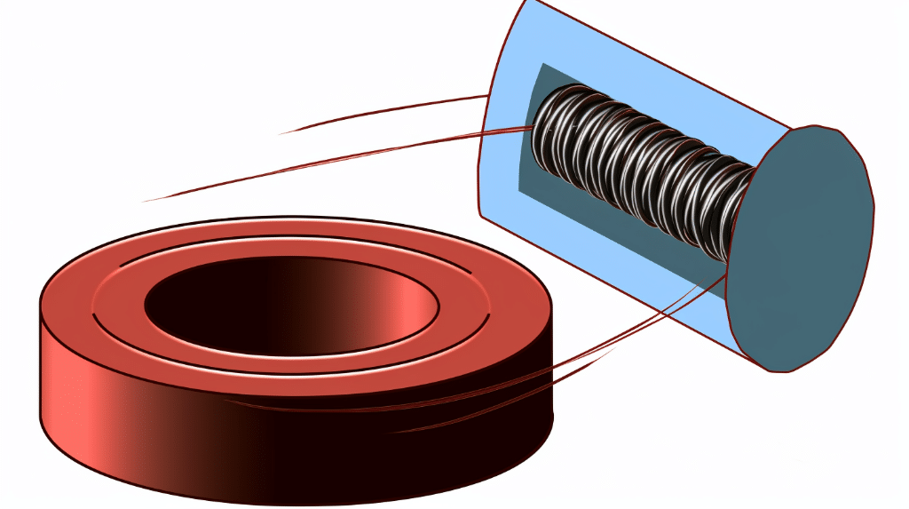
A solenoid is a cylindrical coil of wire that, when carrying an electric current, produces a uniform magnetic field inside the coil. The magnetic field lines inside the solenoid are parallel to the axis of the coil, and the field strength is constant throughout the interior of the solenoid.

The formula for the magnetic field strength (B) inside a solenoid is:

B = μ₀ * n * I

Where:
– B is the magnetic field strength, measured in Teslas (T)
– μ₀ is the permeability of free space, which is a constant equal to 4π x 10^-7 T m/A
– n is the number of turns per unit length, measured in turns/meter (m^-1)
– I is the current flowing through the solenoid, measured in Amperes (A)

This formula is derived from the Biot-Savart law, which describes the magnetic field produced by a current-carrying wire. By considering the cumulative effect of all the current-carrying loops in a solenoid, we can arrive at this simplified expression for the magnetic field.

Factors Affecting the Magnetic Field of a Solenoid

The magnetic field of a solenoid is influenced by several key factors:

  1. Number of Turns (N): Increasing the number of turns in the solenoid will increase the magnetic field strength, as more current-carrying loops contribute to the overall field.

  2. Current (I): Increasing the current flowing through the solenoid will directly increase the magnetic field strength, as per the formula.

  3. Length of the Solenoid (L): The length of the solenoid affects the number of turns per unit length (n = N/L). Longer solenoids with the same number of turns will have a lower n, and thus a weaker magnetic field.

  4. Diameter of the Solenoid: The diameter of the solenoid does not directly affect the magnetic field strength inside the solenoid, but it can influence the overall field distribution and the magnetic field outside the solenoid.

  5. Core Material: Inserting a ferromagnetic material (such as iron) inside the solenoid can significantly increase the magnetic field strength, as the core material will concentrate and amplify the magnetic field.

By understanding how these factors influence the magnetic field, you can design and optimize solenoids for various applications, such as electromagnets, particle accelerators, and magnetic resonance imaging (MRI) systems.

Measuring the Magnetic Field of a Solenoid

To measure the magnetic field of a solenoid, you can use a magnetic field probe or a gaussmeter. The probe should be positioned at the center of the solenoid, along its axis. This ensures that the probe measures the uniform magnetic field inside the solenoid, which is parallel to the axis.

When measuring the magnetic field, it’s important to consider the following:

  1. Background Magnetic Field: The magnetic field measured by the probe will include both the field generated by the solenoid and any background magnetic field present in the environment. To isolate the magnetic field due to the solenoid, you should measure the background field with the current turned off and subtract it from the total field measurement.

  2. Probe Orientation: The magnetic field probe should be oriented to measure the component of the magnetic field that is parallel to the axis of the solenoid. This is typically the strongest and most uniform component of the field.

  3. Probe Positioning: The probe should be positioned at the center of the solenoid, along its axis, to measure the maximum and most uniform magnetic field. Measurements taken closer to the ends of the solenoid may be affected by edge effects and non-uniform field distribution.

  4. Multiple Measurements: It’s recommended to take multiple measurements at different points along the solenoid’s axis to ensure consistency and accuracy. Averaging the results can help reduce the impact of any local variations in the magnetic field.

By following these guidelines, you can obtain reliable and accurate measurements of the magnetic field produced by a solenoid.

Calculating the Magnetic Field of a Solenoid

To calculate the magnetic field of a solenoid, you can use the formula:

B = μ₀ * n * I

Where:
– B is the magnetic field strength, measured in Teslas (T)
– μ₀ is the permeability of free space, which is a constant equal to 4π x 10^-7 T m/A
– n is the number of turns per unit length, measured in turns/meter (m^-1)
– I is the current flowing through the solenoid, measured in Amperes (A)

Let’s go through some examples to illustrate the use of this formula:

Example 1:
A solenoid has 500 turns and a length of 20 cm (0.2 m). If the current flowing through the solenoid is 2 A, what is the magnetic field strength inside the solenoid?

Given:
– Number of turns (N) = 500
– Length of the solenoid (L) = 0.2 m
– Current (I) = 2 A

Step 1: Calculate the number of turns per unit length (n)
n = N / L = 500 / 0.2 = 2500 turns/m

Step 2: Calculate the magnetic field strength (B)
B = μ₀ * n * I
B = (4π × 10^-7 T m/A) * (2500 turns/m) * (2 A)
B = 6.28 × 10^-3 T = 6.28 mT

Therefore, the magnetic field strength inside the solenoid is 6.28 mT.

Example 2:
A solenoid has 1000 turns and a length of 50 cm (0.5 m). If the current flowing through the solenoid is 5 A, what is the magnetic field strength inside the solenoid?

Given:
– Number of turns (N) = 1000
– Length of the solenoid (L) = 0.5 m
– Current (I) = 5 A

Step 1: Calculate the number of turns per unit length (n)
n = N / L = 1000 / 0.5 = 2000 turns/m

Step 2: Calculate the magnetic field strength (B)
B = μ₀ * n * I
B = (4π × 10^-7 T m/A) * (2000 turns/m) * (5 A)
B = 1.257 × 10^-2 T = 12.57 mT

Therefore, the magnetic field strength inside the solenoid is 12.57 mT.

These examples demonstrate how to use the formula to calculate the magnetic field strength inside a solenoid, given the number of turns, length, and current. By varying these parameters, you can explore the relationship between the different factors and the resulting magnetic field.

Practical Considerations and Applications

Solenoids are widely used in various applications, and understanding their magnetic field characteristics is crucial for designing and optimizing these devices. Here are some practical considerations and applications of solenoids:

  1. Electromagnets: Solenoids are commonly used to create electromagnets, which are used in a variety of applications, such as electric motors, generators, and magnetic separation devices.

  2. Particle Accelerators: In particle accelerators, such as cyclotrons and synchrotrons, solenoids are used to create strong, uniform magnetic fields that guide and focus the charged particles along their desired trajectories.

  3. Magnetic Resonance Imaging (MRI): MRI systems rely on powerful superconducting solenoids to generate the strong, uniform magnetic fields required for imaging the human body.

  4. Magnetic Levitation: Solenoids can be used to create magnetic fields that can levitate objects, such as in maglev trains, which use this principle for frictionless high-speed transportation.

  5. Magnetic Shielding: Solenoids can be used to create magnetic fields that can shield sensitive electronic equipment from external magnetic interference, ensuring reliable operation.

  6. Inductive Heating: Solenoids can be used to generate high-frequency alternating magnetic fields, which can be used for inductive heating applications, such as in metal processing and cooking appliances.

  7. Magnetic Separation: Solenoids can be used to create strong magnetic fields that can be used to separate magnetic materials from non-magnetic materials, such as in the recycling of electronic waste.

These are just a few examples of the many applications of solenoids and their magnetic fields. By understanding the principles and calculations involved in determining the magnetic field of a solenoid, you can design and optimize these devices for a wide range of practical applications.
Reference:

  1. Magnetic field due to a coil of N turns and a solenoid – Physics Stack Exchange
  2. Solenoid Magnetic Field Calculator – Omni Calculator
  3. Understanding The Magnetic Field In A Solenoid – FasterCapital

Magnetic Flux Vs. Magnetic Flux Linkage: Comparative Analysis And Facts

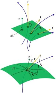
General flux diagram.svg 1 183x300 1

In this article, we will be comparing magnetic flux vs. magnetic flux linkage to understand the difference between them.  

Magnetic flux and flux linkage have quite different meanings, magnetic flux vs magnetic flux linkage. When we talk about magnetic flux, we are referring to the total number of field lines passing through a surface, and in the case of flux linkage, it is associated with the total number of turns. 

Suppose we have a conducting wire with the area A and the magnetic field strength is B. Again, the magnetic lines are falling at a theta. Therefore the magnetic flux becomes:

Φ= B.A

Φ= B A cos θ

Now what we do is turn this conducting wire into coils with 5 turns. In this case, flux linkage becomes: 

λ= N Φ

λ= 5Φ

So this example makes it clear to us about the magnetic flux vs. magnetic flux linkage. Further, on the one hand, we have magnetic flux as scalar and flux linkage as vector. The unit of magnetic flux is weber, and that of flux linkage is weber-turns. 

Magnetic flux vs magnetic flux linkage
Image Credit: Wikipedia

What is magnetic flux linkage surface?

The flux linkage is often confused with magnetic flux. Many consider it to be equal to magnetic flux, but in actuality, it is the extension of the magnetic flux. The loop of the coil is the surface of magnetic flux linkage through which flux is passed. 

For the surface with area A, the magnet flux linkage becomes:

λ= N Φ

λ= N B A

What is the magnetic flux through a closed surface?

As per the Gauss Law of magnetism, we get the magnetic flux through a closed surface. It states that the flux through a closed surface is always equal to zero. 

This is because, through a closed surface, the number of magnetic field lines going in will be equal to the total magnetic lines going out. That is why the total magnetic flux becomes zero through a closed surface. 

What is magnetic flux linkage equation?

According to Faraday’s Law, the change in magnetic flux linkage induces the emf, i.e., electromotive force. This law provides us with the equation of magnetic flux linkage. Therefore the equation becomes:

ɛ  = -d/dt

Here we can see the equation difference of magnetic flux vs magnetic flux linkage. By substituting the value of λ we get:

ɛ = – dNΦ/dt

ɛ = -N dΦ/dt

Magnetic flux linkage formula with angle

The flux linkage formula, as we have seen, is NΦ. Now, if we substitute the formula of magnetic flux in the flux linkage formula, we will get magnetic flux linkage with angle. 

The formula of magnetic flux is given by Φ = B A cos Φ. Substituting this formula in the above formula of flux linkage, we get: 

λ = N B A cos θ

Here,

N is the number of turns

B is the magnetic field

A is the area 

θ is the angle the magnetic field makes with the plane. 

So, using the above formula, we find magnetic flux with an angle. It was all about magnetic flux vs magnetic flux linkage.

Frequently Asked Questions (FAQs)

What is magnetic flux?

The flux provides us with the number of anything passing through anything. 

Magnetic flux gives us the number of the magnetic field that passes through a given surface. It has only magnitude and thus a scalar. Phi is used to represent the magnetic flux. Thus its formula is

Φ= B. A and unit is weber. 

What is magnetic flux density?

As the name suggests, the magnetic flux density provides the density. 

The total perpendicular magnetic flux per unit area gives us the magnetic flux density. The magnetic flux density is usually represented by B. The unit magnetic flux density is weber m2 or Tesla. 

What is flux linkage?

The flux linkages link the magnetic flux with the turns of the conductor. 

When you transform the conductor into turns, then we get flux linkage λ as NΦ. Here Φ is the magnetic flux. It is the change in flux linkage that induces a current in the magnet.

Explain magnetic flux vs magnetic flux linkage. 

The magnetic flux and flux linkage are usually confused, but they differ. Let us understand magnetic flux vs magnetic flux linkage.

The magnetic flux provides us with the information of the total magnetic field coming in or out of the surface. On the other hand, the magnetic flux linkages link this magnetic flux with the turns of a conducting coil.

Also Read:

Is Magnetic Flux A Vector: Detailed Insight And Facts

Surface normal

The total number of magnetic field lines passing through a given area is magnetic flux. Is magnetic flux a vector? Let’s find out. 

Magnetic flux, which tells us about the number of field lines that cross the surface, is a scalar. It is the dot product of two vectors. So, Is magnetic flux a vector? The answer is simply no, but let’s get detailed insight. 

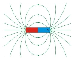
Magnetic field lines are imaginary lines that determine the space around the magnet where its effect is exerted. Whatever may be the type of magnet is, they will always consist of two poles, a north and south. 

The magnetic field lines outside the magnet are from north-south, while inside, the direction gets reversed. The region where lines are clustered is the region of strong magnetic effect. As field lines move apart, magnetic effects become weak. 

The magnetic flux does let us know about the field lines that pass through any plane. It is an important concept that lets us know about the effect of any magnet.

download 2
Image Credit: Wikipedia

Why is magnetic flux a vector?

It is well known that a magnetic field has direction and thus is a vector, but this does not make magnetic flux also a vector. The magnetic flux is the scalar product of magnetic field lines and surface area.

is magnetic flux a vector
Image Credit: Wikipedia

Thus we have the formula as:

Φ= B.A

Φ = B A cos θ

Here,

Φ is the magnetic flux

B denotes the magnetic field 

A is the surface area. 

θ is the angle made by the field lines with a closed surface. 

The fundamental unit of magnetic flux is Volt-second, and the standard unit is weber (Wb).

The angle theta plays a vital role in determining the magnetic flux over a given surface. In case the magnetic field lines are normally falling to the surface, then the magnetic flux will be zero. Let us understand this. 

Φ = B A cos θ

Substituting the value of theta as 90°, we get

Φ = B A cos 90

We know cos 90 is equal to 0; thus, magnetic flux becomes zero. 

Is magnetic flux density vector?

Apart from magnetic flux, the magnetic flux density is also used to describe the effect of a magnet. Many get confused between these two magnetic concepts and use them to describe the same thing. But magnetic flux and magnetic flux density are quite different.

If we talk in simple language, then magnetic flux density tells us about the density of the field. The high value of magnetic flux indicates that the magnetic effect is strong, and a small value means a low magnetic effect. 

Magnetic Flux density is dependent on the area. The area is vector and changes with direction. This brings us to the conclusion that magnetic flux density is also a vector. 

As the name suggests, magnetic flux density determines the flux per given area, which brings us to the formula: 

B = Φ/A

Here, B is the magnetic flux density

Φ is the magnetic flux

A is the given surface area. 

The standard unit of magnetic flux density is Tesla. It is a vector quantity as it is in a way similar to the electric field by the relation B = εE. Here since ε is the constant, magnetic flux density is very much proportional to the electric field. As we know, electric fields have both magnitude and direction so is the magnetic flux density. 

Is magnetic flux linkage a vector?

Magnetic flux linkage is a value that represents the linking of a magnetic field with the coil. We can simply say that the magnetic flux linkage is the flux times the number of turns in the coil. 

It is generally used for solenoids. For example, a solenoid has 25 turns. Suppose the magnetic flux through the surface is 5 weber. Then magnetic flux linkage would be a product of magnetic flux and number of turns, i.e., 125. So, it is nothing but the total flux. 

The emf is induced in case the magnetic flux changes. This magnetic flux is termed magnetic flux linkage. And thus, it is the vector quantity as it is proportional to the current, which is also a vector quantity. So here, it is clear that magnetic flux is scalar, but flux linkage is a vector. 

How can magnetic flux be a scalar, but magnetic flux density is a vector?

Flux, in general in all the cases, is a scalar as it represents the total number. The number of anything is never associated with the direction. For instance, let’s count the number of birds flying over your roof. It doesn’t matter in which they fly; the total number will be a scalar. 

Let us look at a more proper explanation; we know that area and magnetic field are both vectors. Now in the figure above, we have given a surface with area A and magnetic field passing making angle theta with the surface. 

We know magnetic flux will be a product of magnetic field and area that is:.’

Φ = BA

From the figure, we can see that on splitting B into its component, we get B cos θ . Therefore:

Φ = B cos θA

Φ = B A cos θ

Φ = B . A

Which is a scalar dot product, and hence magnetic flux is a vector. On the other hand, the magnetic flux density is dependent on the surface area; it will vary in different areas. Since the area is a vector quantity, so is the magnetic flux density. Now we have got the answer to is magnetic flux a vector and why magnetic flux density is a vector. 

Frequently Asked Questions (FAQs)

What is magnetic flux?

For studying the magnetic field, magnetic flux is a vital concept. 

The magnetic field lines that cross a particular area, their total number, are said to be the magnetic flux. Its unit is weber and Tesla.

Is magnetic flux a vector quantity?

Though the quantities involved to find magnetic flux are vector, it is a scalar.  

How is magnetic flux different from magnetic flux density?

Magnetic flux and flux density have a minute but significant differences. 

Magnetic flux is used to describe the number of magnetic field lines, whereas magnetic flux density tells us about the density of the field lines—both in the given area. 

Is the magnetic field a vector?

The magnetic field has a significant direction and therefore is a vector. 

The magnetic field lines start from the north pole and enter the south pole. Whereas inside the magnet, the direction is opposite; it moves from the south pole to the north pole. 

What is magnetic flux linkage?

The magnetic flux linkage is usually the concept of solenoids. 

To understand it in an easy way, consider a solenoid has ‘n’ number of turns, and magnetic flux through one turn is Φ. Then flux linkage will be nΦ, which is basically the total flux through a solenoid. 

Read more about

Magnetic Flux In A Wire
Magnetic Flux In A Magnetic Circuit
Magnetic Flux and Time
Is Magnetic Flux Negative
9 Real World Magnetic Flux Examples
Magnetic Flux In A Transformer
Magnetic Flux In a Coil
Magnetic Flux And Magnetic Induction
Is Magnetic Flux Constant
Is Magnetic Field A Vector
Magnetic Flux In A Solenoid
Magnetic Flux and Voltage
Is Magnetic Flux Zero
Is Magnetic Flux A Magnetic Force

Also Read:

How to increase the strength of magnetic field: Different methods and facts

how to increase strength of a magnetic field 0

How to Increase the Strength of a Magnetic Field

Magnetic fields play a crucial role in many aspects of our lives, from the operation of electric motors to the functionality of MRI machines. Understanding how to increase the strength of a magnetic field can be valuable knowledge, whether you are an enthusiast experimenting with magnets or a scientist conducting advanced research. In this blog post, we will delve into the basics of magnetic fields, explore the factors influencing their strength, and discuss practical ways to amplify their power. So let’s get started!

Understanding the Basics of Magnetic Fields

how to increase strength of a magnetic field 3

Before we dive into increasing the strength of a magnetic field, it is essential to grasp the fundamentals. A magnetic field is a region in space where a magnetic force can be detected. It is generated by moving electric charges, typically electrons. Magnetic fields are represented by magnetic field lines, which indicate the direction and strength of the field.

Factors Influencing the Strength of a Magnetic Field

how to increase strength of a magnetic field 2

Several factors influence the strength of a magnetic field. Understanding these factors is crucial to increasing the field’s intensity effectively.

  1. Current: The amount of electric current flowing through a conductor is directly proportional to the strength of the magnetic field it produces. A higher current will result in a stronger magnetic field, while a lower current will produce a weaker field. This relationship is described by Ampere’s Law.

  2. Coil Turns: The number of turns in a coil of wire also affects the strength of a magnetic field. Increasing the number of turns increases the magnetic field strength proportionally. This relationship is known as Faraday’s Law.

  3. Magnetic Material: Using a magnetic material, such as iron or neodymium, can significantly enhance the strength of a magnetic field. These materials have high magnetic permeability, meaning they can efficiently concentrate and amplify magnetic field lines.

Practical Ways to Increase Magnetic Field Strength

Now that we have a good understanding of the factors influencing magnetic field strength, let’s explore some practical ways to increase it.

  1. Increasing the Current: To increase the strength of a magnetic field, you can increase the current flowing through a conductor. This can be achieved by using a higher voltage power supply or by reducing the resistance of the circuit. However, it is crucial to ensure that the conductor and power supply can handle the increased current without overheating or damaging the equipment.

  2. Adding Coils: Adding more turns to a coil of wire can significantly boost the magnetic field strength. For example, wrapping a wire around an iron core multiple times will increase the number of coil turns and consequently increase the magnetic field intensity.

  3. Using Magnetic Materials: As mentioned earlier, using magnetic materials can greatly enhance the strength of a magnetic field. Placing a magnetic material, such as iron or a neodymium magnet, near the source of the magnetic field will concentrate and amplify the field lines. This technique is commonly used in applications like magnetic separators and speakers.

  4. Optimizing the Geometry: The shape and arrangement of the magnetic field source can also impact its strength. For example, using a solenoid (a cylindrical coil of wire) can create a more uniform and concentrated magnetic field compared to a simple straight wire.

Changing the Strength of a Magnetic Field

Now that we have explored practical ways to increase the strength of a magnetic field let’s discuss how we can alter the field’s strength by manipulating certain factors.

The Role of Current in Magnetic Field Strength

To understand the relationship between current and magnetic field strength, we can turn to Ampere’s Law. Ampere’s Law states that the magnetic field strength around a current-carrying conductor is directly proportional to the current flowing through it. Mathematically, this relationship is expressed as:

B = mu_0 cdot I cdot frac{N}{L}

Where:
B is the magnetic field strength
mu_0 is the permeability of free space (a constant)
I is the current flowing through the conductor
N is the number of turns in the coil
L is the length of the conductor

From this equation, we can see that increasing the current (I) or the number of coil turns (N) will directly increase the magnetic field strength (B).

The Impact of Coil Turns on Magnetic Field Strength

Expanding on the concept of coil turns, let’s take a deeper look at Faraday’s Law. Faraday’s Law states that the magnetic field strength is directly proportional to the number of turns in a coil of wire. Mathematically, we can express this relationship as:

B = mu_0 cdot I cdot N

Where all the variables have the same meaning as in Ampere’s Law.

This equation demonstrates that increasing the number of coil turns (N) will directly increase the magnetic field strength (B). Therefore, adding more turns to a coil is an effective way to boost the magnetic field intensity.

Experiment: Altering Current and Coil Turns to Change Magnetic Field Strength

To solidify our understanding, let’s conduct a simple experiment. We will use a solenoid (a coil of wire) connected to a power supply.

  1. Set up a solenoid by coiling a wire around a cylindrical tube.
  2. Connect the solenoid to a power supply.
  3. Measure the current flowing through the solenoid using an ammeter.
  4. Use a magnetic field strength measuring device, such as a Hall probe, to measure the magnetic field strength at different current values.
  5. Record the readings and observe how the magnetic field strength changes as the current increases.
  6. Repeat the experiment, this time keeping the current constant and varying the number of coil turns.
  7. Measure the magnetic field strength at different coil turn values and observe the changes.

By altering the current and coil turns, you will observe firsthand how these factors directly impact the strength of a magnetic field.

Increasing the Strength of a Magnet

how to increase strength of a magnetic field 1

In addition to manipulating the magnetic field generated by a current-carrying conductor, we can also increase the strength of a magnet itself. This can be accomplished through various techniques that optimize the magnet’s properties.

The Science Behind Magnet Strength

To understand how to enhance magnet strength, we need to explore the science behind it. Magnets consist of aligned magnetic domains, which are microscopic regions where atomic dipoles align in a specific direction. When these domains are properly aligned, the magnet exhibits a strong magnetic field.

Techniques for Enhancing Magnet Strength

Here are some techniques you can use to increase the strength of a magnet:

  1. Magnetic Field Alignment: Exposing a magnet to a strong external magnetic field and then slowly reducing the field can help realign the magnetic domains within the magnet, resulting in increased strength.

  2. Heat Treatment: Subjecting a magnet to high temperatures can temporarily disrupt the alignment of the magnetic domains. Upon cooling, the domains can reorient themselves in a more favorable arrangement, potentially increasing the magnet’s strength.

  3. Using Stronger Magnetic Materials: Choosing magnets made from materials with higher magnetic properties, such as neodymium magnets, can significantly boost their strength. These materials have larger magnetic moments per atom, leading to stronger magnetic fields.

Experiment: Testing the Strength of Enhanced Magnets

To see the effects of these techniques, you can conduct a simple experiment:

  1. Start with a regular magnet and measure its strength using a magnetic field strength measuring device.
  2. Expose the magnet to a strong external magnetic field (e.g., by using another powerful magnet) for a period of time.
  3. Slowly reduce the external magnetic field and measure the magnet’s strength again.
  4. Alternatively, subject the magnet to heat by placing it in an oven or heating it with a flame. Be cautious when handling hot objects.
  5. Allow the magnet to cool down, and measure its strength once more.
  6. Compare the magnetic field strength before and after applying these techniques to observe any changes.

By conducting this experiment, you will gain insight into how these techniques can enhance the strength of magnets.

Strengthening the Magnetic Field of a Solenoid

A solenoid is a coil of wire wound in a helical shape. It can produce a magnetic field when an electric current flows through it. By understanding the relationship between a solenoid and magnetic field strength, we can explore ways to increase the field’s intensity.

Understanding the Function of a Solenoid

A solenoid is designed to generate a magnetic field that is concentrated within its coil. Its magnetic field strength is determined by factors such as the number of coil turns, the current flowing through the coil, and the length of the solenoid.

The Relationship Between Solenoid and Magnetic Field Strength

The magnetic field strength (B) produced by a solenoid can be calculated using the following equation:

B = mu_0 cdot N cdot I

Where:
B is the magnetic field strength
mu_0 is the permeability of free space
N is the number of coil turns in the solenoid
I is the current flowing through the solenoid

From this equation, we can conclude that increasing the number of coil turns (N) or the current (I) will directly increase the magnetic field strength (B).

Experiment: Increasing the Magnetic Field Strength of a Solenoid

To visualize the impact of these factors, let’s perform an experiment:

  1. Set up a solenoid by wrapping a wire around a cylindrical tube.
  2. Connect the solenoid to a power supply and ammeter to measure the current.
  3. Use a magnetic field strength measuring device to measure the magnetic field strength at different current values.
  4. Record the readings and observe how the field strength changes as the current increases.
  5. Repeat the experiment, this time keeping the current constant and varying the number of coil turns.
  6. Measure the magnetic field strength at different coil turn values and observe the changes.

By conducting this experiment, you will gain a practical understanding of how alterations in current and coil turns impact the magnetic field strength of a solenoid.

Boosting the Magnetic Strength of an Electromagnet

An electromagnet is a type of magnet that produces a magnetic field when an electric current passes through it. By exploring the basics of electromagnetism and understanding the factors that influence an electromagnet’s strength, we can learn how to build a more powerful electromagnet.

The Basics of Electromagnetism

Electromagnetism is the phenomenon where electricity and magnetism are interconnected. When an electric current flows through a conductor, it generates a magnetic field around the conductor. This magnetic field can be enhanced by optimizing certain factors.

Factors that Increase the Strength of an Electromagnet

There are several ways to increase the strength of an electromagnet:

  1. Increasing the Current: As we have discussed earlier, the strength of an electromagnet is directly proportional to the current flowing through it. By increasing the current, we can amplify the magnetic field produced by the electromagnet.

  2. Using a Magnetic Core: Similar to enhancing the strength of a regular magnet, using a magnetic core, such as iron, can significantly increase the strength of an electromagnet. The magnetic core concentrates the magnetic field lines, resulting in a more powerful electromagnet.

  3. Optimizing Coil Turns: Adding more turns to the coil of wire wrapped around the electromagnet can further boost its strength. Increasing the number of turns increases the magnetic field intensity, making the electromagnet more potent.

Experiment: Building a Stronger Electromagnet

Let’s put the theory into practice and conduct an experiment to build a stronger electromagnet:

  1. Wrap a wire around a magnetic core, such as an iron nail or a piece of iron rod.
  2. Connect the wire to a power supply and ammeter to measure the current flowing through the electromagnet.
  3. Use a magnetic field strength measuring device to measure the magnetic field strength at different current values.
  4. Record the readings and observe how the field strength changes as the current increases.
  5. Repeat the experiment, this time keeping the current constant and varying the number of coil turns.
  6. Measure the magnetic field strength at different coil turn values and observe the changes.

By performing this experiment, you will gain a hands-on experience of how current, magnetic cores, and coil turns influence the strength of an electromagnet.

Practical Applications of Increased Magnetic Field Strength

Understanding how to increase the strength of a magnetic field has various practical applications. Let’s take a moment to highlight a few:

  1. Electric Motors: Electric motors rely on magnetic fields to generate motion. By increasing the strength of the magnetic field, we can improve the efficiency and performance of electric motors.

  2. MRI Machines: Magnetic resonance imaging (MRI) machines use powerful magnetic fields to create detailed images of the human body. Increasing the strength of the magnetic field in an MRI machine can enhance image quality and provide more accurate diagnoses.

  3. Speakers and Headphones: Speakers and headphones utilize magnets to convert electrical signals into sound. By amplifying the magnetic field strength, we can achieve louder and more immersive audio experiences.

  4. Magnetic Separators: Magnetic separators are used in various industries to separate magnetic materials from non-magnetic ones. Increasing the strength of the magnetic field in these separators improves their efficiency in separating and purifying materials.

Encouragement for Further Exploration and Experimentation

Congratulations! You now have a solid understanding of how to increase the strength of a magnetic field. By exploring the basics, understanding the factors that influence magnetic field strength, and experimenting with different techniques, you can continue to expand your knowledge and delve deeper into the fascinating world of magnetism. So keep exploring, experimenting, and uncovering the endless possibilities that magnetism has to offer!

How can increasing the strength of a magnetic field affect the understanding of magnetic flux and field?

Increasing the strength of a magnetic field can have a significant impact on our understanding of magnetic flux and field. Magnetic flux and magnetic field are closely related concepts in electromagnetism. By increasing the strength of a magnetic field, we can observe changes in the magnetic flux passing through a given area. This understanding of the relationship between magnetic flux and magnetic field can be further explored in the article on “Understanding Magnetic Flux and Field”. The article delves into the intricacies of these concepts and provides valuable insights into their connection.

Numerical Problems on how to Increase Strength of a Magnetic Field

Problem 1

A solenoid consists of 200 turns per meter and carries a current of 2A. The length of the solenoid is 0.5m. Calculate the magnetic field strength inside the solenoid.

Solution:

Given:
Number of turns per meter, N = 200
Current, I = 2A
Length of the solenoid, l = 0.5m

The magnetic field strength inside a solenoid can be calculated using the formula:

B = mu_0 cdot frac{N cdot I}{l}

where
mu_0 is the permeability of free space (mu_0 = 4pi times 10^{-7} , text{Tm/A}).

Substituting the given values into the formula:

B = 4pi times 10^{-7} , text{Tm/A} cdot frac{200 , text{turns/m} cdot 2 , text{A}}{0.5 , text{m}}

Simplifying the expression:

B = 8pi times 10^{-7} , text{T} cdot text{m/A}

Therefore, the magnetic field strength inside the solenoid is 8pi times 10^{-7} , text{T} cdot text{m/A}.

Problem 2

A circular loop of wire with radius 0.1m carries a current of 5A. Calculate the magnetic field strength at the center of the loop.

Solution:

Given:
Radius of the loop, r = 0.1m
Current, I = 5A

The magnetic field strength at the center of a circular loop can be calculated using the formula:

B = frac{mu_0 cdot I}{2r}

where
mu_0 is the permeability of free space (mu_0 = 4pi times 10^{-7} , text{Tm/A}).

Substituting the given values into the formula:

B = frac{4pi times 10^{-7} , text{Tm/A} cdot 5 , text{A}}{2 cdot 0.1 , text{m}}

Simplifying the expression:

B = 10pi times 10^{-6} , text{T}

Therefore, the magnetic field strength at the center of the loop is 10pi times 10^{-6} , text{T}.

Problem 3

A current-carrying wire produces a magnetic field of strength 2 x 10^{-5} T at a distance of 0.02m from the wire. Calculate the current flowing in the wire.

Solution:

Given:
Magnetic field strength, B = 2 times 10^{-5} , text{T}
Distance from the wire, r = 0.02 , text{m}

The magnetic field strength around a current-carrying wire can be calculated using the formula:

B = frac{mu_0 cdot I}{2pi r}

where
mu_0 is the permeability of free space (mu_0 = 4pi times 10^{-7} , text{Tm/A}).

Rearranging the formula to solve for the current I:

I = frac{2pi r cdot B}{mu_0}

Substituting the given values into the formula:

I = frac{2pi cdot 0.02 , text{m} cdot 2 times 10^{-5} , text{T}}{4pi times 10^{-7} , text{Tm/A}}

Simplifying the expression:

I = 10 , text{A}

Therefore, the current flowing in the wire is 10 , text{A}.

Also Read:

Magnetic Flux Vs Magnetic Field: Different Aspects and Facts

image 35

We often get confused between Magnetic flux and magnetic field. Here in this article, we will discuss differences, similarities, and other interesting facts about magnetic flux vs magnetic field   

Magnetic flux and magnetic field both are characteristics of a magnet. The major distinction among magnetic flux and the magnetic area is that magnetic area is area close to the magnet or current-sporting conductor wherein magnetic pressure may be felt, on the alternative hand, magnetic flux is the range of magnetic area traces passing via an area. 

Magnetic field   

A magnetic field is an area in space where mobile ions and magnetic polarities are subjected to a force (Considering the lack of electric field, because that also exerts force).   

The force felt is proportional to the intensity of the magnetic area. Magnetic field lines may be used to symbolize a magnetic field. Magnetic field lines are brought nearer together under a greater magnetic field.  

On the magnetic field line, an arrowhead can be made such that the field lines flow in the direction of a north pole positioned in the magnetic field. Placing metal particles in a magnetic field and letting them line up produces the form of magnetic field lines.  The force experienced by a particle of charge q moving through the magnetic field at a velocity may be used to describe the magnetic field intensity;  

F= qv * B

If the magnetic field and motion of particles are perpendicular to each other, then we get   

F= qvB

When the word “magnetic field” refers to a quantity rather than a place, it is almost always refers to the magnetic field strength. The Tesla is the SI unit for measuring magnetic field intensity (T). The depth of the Earth’s magnetic field varies through location, however it’s far at the order of microteslas.

The quantity of magnetic subject that passes throughout an area is measured with the aid of using magnetic flux. Magnetic flux is described as the “number” of magnetic subject strains journeying thru a given area in a simplified manner. The term “magnetic subject” refers to a place wherein a magnetic pressure can be experienced. The magnetic subject is totally depending on the magnet that generates it. Magnetic fields of a few teslas are produced by magnets used in MRI equipment in hospitals, and the highest magnetic field we’ve been able to build is roughly 90 T.  

Magnetic flux  

The quantity of magnetic subject that passes throughout an area is measured with the aid of using magnetic flux.  As a result, this amount is affected not only by the strength of the magnetic field but also by the size of the region.  Magnetic flux is described as the “number” of magnetic subject strains journeying thru a given area in a simplified manner. 

The precise definition of magnetic flux, on the other hand, is presented via vector calculus. The magnetic flux Φ is calculated by integrating the magnetic field across a surface in this way;   

Φ = ∫B.dA

If magnetic field of strength B passes normal to an area A, the above equation simplifies into this  

Φ = BA

SI unit of magnetic flux is Weber (Wb). 1Wb= 1T m2

The net magnetic flux across a closed surface, according to Gauss’s equation of magnetism, is zero. This indicates that magnetic field lines make complete loops, and thus a north pole without a south pole, and vice versa is impossible. Even though no research has yet identified them, some hypotheses anticipate the presence of so-called “magnetic monopoles.”  

The magnetic flux is, if we use a typical smooth surface with area A as our testing area and that there is an angle θ between the normal to the surface and a magnetic field vector (magnitude B).  

Φ = B A cosθ

where A , the area vector, is described as a vector perpendicular to the loop’s plane with a magnitude equal to the loop’s area AA . The area vector is measured in m2 in SI units. 

The angle is 0 when the surface is perpendicular to the field, and the magnetic flux is simply BA. 


Magnetic flux vs magnetic field

S. no. Magnetic flux  Magnetic field 
1. The amount of magnetic field lines that flow through a certain region is referred to as magnetic flux.    The term “magnetic subject” refers to a place wherein a magnetic force can be experienced. 
2. Magnetic flux is influenced by the area and direction of a region as well as the magnet that generates the field.    
The magnetic subject is totally depending on the magnet that generates it. 
3. The SI unit of magnetic flux is Weber (Wb).  
1Wb= 1T m2
The Tesla is the SI unit for measuring magnetic field intensity (T).  
4. Φ = BA F= qvB

Magnetic flux vs magnetic field strength  

The amount of the magnetic field in a material that arises from an external current and is not intrinsic to the material itself is known as magnetic field strength, often known as magnetic intensity or magnetic field intensity.  

It is calculated in amperes per meter and is denoted with the aid of using vector H. H is described as

H= B/(mu-M) , in which B is the magnetic flux density, that’s a degree of the actual magnetic field inside a fabric expressed as a attention of magnetic field lines, or flux, per unit cross-sectional area; M is the magnetization.  

The magnetic field H may be assumed of just like the magnetic discipline generated with the aid of using modern-day flowing via wires, at the same time as the magnetic field B may be concept of as the overall magnetic field, which incorporates the contribution M from the magnetic houses of the substances withinside the field. 

The magnetizing field H is weak whenever a current flows in a coiled wire around a soft-iron cylinder, however, the actual average magnetic field (B) inside the iron could be numerous times greater since B is vastly strengthened by the orientation of the iron’s numerous tiny natural atomic magnets in the field’s way.  

Magnetic field and magnetic flux relation

A magnetic field is represented through separate vectors: one known as magnetic flux density, or magnetic induction, is represented through B, and every other known as magnetic field strength, or magnetic field intensity, is represented through H. 

H= B/(mu-M) it shows relationship between magnetic flux density that is B and magnetic field intensity that is H.

Difference between magnetic flux and magnetic flux density   

Magnetic flux is a scalar quantity, at the same time as magnetic flux density is a vector quantity. The scalar is product of the magnetic flux density and the vicinity vector is magnetic flux. Magnetic flux is a constant value on the other hand magnetic flux density is varying quantity. 


Problems  

Problem 1:

In a homogeneous magnetic field of strength 0.6 T, a rectangular loop with a side length of 4 cm is placed so that the loop’s plane creates a 45-degree angle with the magnetic field. What is the flux that flows through the square loop?

magnetic flux vs magnetic field
Magnetic flux vs magnetic field

Solution: Given values are ;

l = 4cm

B= 0.6T

             Φ = 45°

Placing given values in magnetic flux formula,  

    Φ = B A cos θ

    Φ= (0.6)(0.04*0.04)\cos 45°

    Φ= 0.68mWb

Angle θ = 45° is the angle between B and a unit vector normal to the surface.   

And the given angle θ = 45° is with surface of the loop not with vector normal to the surface that is

n^

Problem 2:

A circular loop of area 200cm2 placed in the xz plane

Then, a uniform magnetic field of B= 0.2i^+0.3j^T applied on it. What is the   

(a) Magnitude of the magnetic field   

(b) Magnetic flux through the square loop?  

Solution:   

(a) The magnitude of a vector such as   

R= Rxi^+Ry j^ is given by the formula ;  

R= Rxi^+Ryj^= √Rxi^2+Ryj^2

so, strength (magnitude) of the magnetic field is determined as  

B= √[(0.2)2+(0.3)2]= 0.36 T

(b) This circular loop is positioned at right angle with the y  axis so a unit vector perpendicular to it is written as             

y^=n^

Now we use the scalar definition of magnetic flux as   Φ =Bn^ to find it as below  

 Φ =Bn^

= 0.2i^+0.3j^c.j^*200*10-4

= (0.2i^c.j^+0.3j^.j * 0.2)

= 0.3*0.2

= 0.06 T

We have used 1cm2= 10-4m2 this conversion rule in above solution.

Frequently asked questions |FAQs   

Q. What is the distinction between B and H?  

Ans. The distinction between B and H is that B represents magnetic flux density whereas H represents magnetic field strength.  

Q. When is the magnetic flux at its greatest?  

Ans. When the magnetic flux across a coil is equal to zero, it is at its peak. As a result, equal this formula to zero and calculate the angle between the coil’s plane and the lines of force.  

Q. On what parameter magnetic flux depends?  

Ans. The magnetic flux is determined by the surface form and the contained current.  

Q. What is the relationship between magnetic field and flux?  

Ans. The magnet has characteristics like magnetic field and flux. The magnetic field is the space where mobile ions are subjected to force, and the magnetic flux indicates how many magnetic lines of force travel through it. A closed-loop is formed by the magnetic lines of force. 

Q. What causes a magnetic field to change?


Ans. The term “change in the magnetic field” refers to a shift in magnetic field intensity
. As we get closer to the magnet, the magnetic strength grows, and as we get further away, it diminishes. As a result, if a magnet is pushed towards or out from an electric circuit, the magnetic field intensity of that moving bar magnet will affect the circuit.

Q. How magnetic field generates currents?

Ans: Current is induced by a shift in magnetic field in the following way:

The above-mentioned shift in magnetic field strength causes emf.The electric potential (voltage) that permits the movement of charges per unit time is known as the electromagnetic field (EMF).The electric current is created by the passage of charges. This current is known as induced current because it is induced by a variation in magnetic field intensity.


Also Read:

How is Magnetic Field Produced: Detailed Insight And Facts

8295846265 751a5f159c 300x300 1

How is magnetic field produced is one of the important questions that arise. We know that it is the field that influences the electric charges, electric field and the electric current in that system.

It is a universal fact that a magnetic field is produced only when the electric field is present in a system. When an electric current is passed over an element, it instantly creates its electric field only due to its passing.

After the electric field is produced, the magnetic field’s entry is next. Here is the answer to the question of how is magnetic field is produced. So on a wining material when current is passed magnetic field is instantly produced.

Several experiments explain how its magnetic field is produced. And now we take a small example of a solenoid. This element produces a magnetic field when an electric current is produced.

Due to the movement of charges, which creates an electric field. Magnetic field is created due to one of these reasons.

Magnetic field produced by the solenoid

A solenoid is a thin long wire wound around an element. This thin material will help conduct electric current in the system. An instant electric field is created when the current is passed over it. This, in turn, produces a magnetic field.

A solenoid produces a magnetic field because it uses simple means, unlike the rest. It converts electric current into mechanical, for instance, in a switch.

Inside a switch, a solenoid converts the electric current into mechanical action. Solenoid depends on the magnetic field produced and the number of its turns.

In this kind of element called solenoid it is possible to resolve to reverse the magnetic field that is produced by passing electricity.

solenod
“Solenoid spring mod” by oskay is licensed under CC BY 2.0

Which of the method applied to produce the magnetic field

Fundamentally three different methods produce magnetic fields:

Permanent Magnets:

Permanent magnets are magnetized elements using electric current when a material is wound around an element. A permanent magnet is made by striking a ferromagnetic material or two magnets.

For example, two magnets are taken and made to face opposite poles. When the ends of the magnets are beaten to high temperature, it finally becomes a permanent magnet.

The magnetic field in a particular system can also be created by the use of a permanent magnet. This permanent magnet creates a force on other magnets and creates an instant magnetic field.

355133836 f9075e699f b
“Magnets” by steven m is licensed under CC BY 2.0

Electromagnets:

In this type of element an electric current is passed over the element so that it gets magnetized instantly. The conventional current is created when the heat escapes from the system.

Through which the electric field is produced. One of the few reasons for the magnetic field production in an element is due to the presence of electric field.

An advantage to be noted is that an electric field is a cause for the magnetic field to be produced in this electromagnet. The use of the electromagnet can control the magnetic field produced in an element.

At certain times, the permanent magnet creates a good magnetic field. It is also strong enough, but it becomes weak when used in specific materials and requires intense magnetic flux.

At this point, the aid of electromagnet comes into act. The advantage of electromagnet over a permanent magnet is that the magnetic field is created is much stronger. In an electromagnet, electricity is applied to create a stronger magnetic field.

The word electromagnet itself defines an electric current and magnetic field. How is the magnetic field produced, the question most asked, and the above explanation does the justice.

Earth’s Magnetic Field:

This has the strongest fields compared to the other conventional field inside the earth. It is caused by solidifying the liquid iron core of the Earth.

We all know that the magnetic fields are stronger at the poles. It is much stronger when it comes to the Earth’s magnetic field.

Like any other magnetic field, even the Earth’s magnetic field is maintained and controlled. Geodynamo controls and maintains the magnetic field of the earth.

How is magnetic field created in an electromagnet

It is evident from all the studies that an electromagnet is way more convenient than any other magnet to produce a strong magnetic field.

Simple because other magnets produce a magnetic field, but we don’t know. Hence we chose a safer method to produce the magnetic field.

A temporary magnet produces a magnetic field but is weak and of no use. Hence here the use of a permanent magnet comes into act. From which a proper magnetic field is created. The magnetic field is weak, so it can’t be applied to any system.

Hence electromagnet always comes to the rescue of producing a much stronger magnetic field. This type of electricity is employed to create much stronger magnetic flux lines.

Process behind producing a magnetic field using an electromagnet

Firstly we need to be aware of how is an electromagnet made. The process is simple. We must take an element over which a wire is wound around. This wire is called a solenoid.

The solenoid is a simple thin long wire with n number of turns. This material is wound around a conducting element, and when the electric current is passed through it, an instant electric field is produced.

The process behind it is, the electric current is passed over the wound material since it is in circularly wound, and when current is applied, it produces the magnetic flux. The magnetic field lines are in circular mode.

Finally, a magnetic field is produced via a current-conducting material with a solenoid wound.

How are magnetic fields created in planets

The molten liquid generally produces a magnetic field in planets in the core of the planet and the planet’s motion. A magnetic field is easily created since a liquid iron is present in the planet’s core.

Like any other magnets, planets do have poles. These poles are the reason for the attractive and repellant force present.

Like any other magnetic field production by producing electric current, similarly the same on planets too. The electricity in planets is produced when the liquid present at the planet’s core is churned every time.

This electricity created produces a magnetic field on the planet. The magnetic field in the planets acts as an extensive bar magnet. It is also the reason for the rotational axis of the planets.

Why are magnets always dipoles

It is universal that there is something called north and south, east and west. Our Earth consists of north and south poles, and the horizontal is called the equator and not as east and west.

Likewise, another element that has a north pole and south pole is called as magnet. As far as science is considered, monopole seems not to exist. And a magnet cannot be made without two poles.

Magnets are particularly has as a dipole existence due to the fact that the ends of the magnet have been named as north and south poles respectively. Another point to be remembered is that poles repel and unlike poles attract. From this very fact, there arises a term called a magnetic dipole.

A magnetic dipole is the analogy of an electric dipole in which there are opposite charges at the ends of the electric dipole. The dipole is the reason for a closed-loop in any magnetic system.

How is magnetic field produced on Earth

Earth is the giant magnet of all times. The reason behind it is the magnetic fields produced on the Earth are much stronger than the conventional ones.

On every planet, there is a molten liquid of a particular metal. Likewise, liquid molten iron ore is present in the Earth’s core. This liquid reacts with the motion of the Earth, creating a stronger magnetic field.

The movement of these liquids and churning of them creates strong electricity. This electricity is one of the main reasons for how magnetic field is produced on Earth.

Earth acts as the giant bar magnet to manage the magnetic field by itself. It is also the reason behind the Earth’s rotation from its axis.

Also Read:

What Produces the Strength of a Magnetic Field: Different Methods and Facts

CNX Chem 06 04 NOFNe img

In this article, we are going to discuss what produces the strength of a magnetic field and the different factors responsible for its formation.

What produces the strength of the magnetic field is the magnetic flux passes through a unit length of the conductor and increases as the flux density per unit length increases.

Magnetic Field and It’s Intensity

Let us now see different methods and some facts of a magnetic field.

First of all, do you all know how the magnet was discovered?

A shepherd called Magnas who lived in Greece used to carry a stick along with him to control the herd of sheep and goats which had an iron underneath which stuck to the rock. The rock was a natural magnet, rich in iron (Fe content) called Magnetite. Hence the discovery of the magnet took place in Greece and now that place is called Magnesia, a name based on the discovery of magnet.

As the magnetic field strength of the Earth is greatest at the North pole and the South pole, the magnet is always aligned in the North-South direction and hence is used to locate the direction by sea ventures. Especially, clinometers are used to measure the angle of elevation of the rocks by most geologists.

What produces the strength of a Magnetic Field

Magnetic field strength is a force needed to generate a flux density in a material per unit length of the material and represented as:

H=(B/μ)-M

Where B is a magnetic flux density,
M is magnetization and
m is magnetic permeability.

Magnetic strength depends on the total magnetic field lines which are pervasive through the total cross-sectional area of the material. These magnetic field lines are known as magnetic flux, and the density of the magnetic flux is directly correlated to the strength of the field. The magnetic flux density primarily depends upon the number of electron spins or the dipole moment in the material.

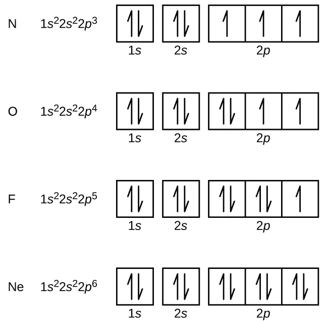
In an atom, electrons are found paired with electrons with opposite spin and it is usually found in the case of noble gases elements which have complete outmost valence shell and all electrons are paired with each other; an example of such elements are Helium, Neon, Argon, Krypton, Xenon, Radon.

CNX Chem 06 04 NOFNe img
Electronic configuration;
Image Credits: allencany1983

Atoms that have unpaired electrons pair with electrons from the other atom to complete their outer shell and become a stable element. Those atoms with unpaired electrons yield a magnetic field. The unpaired electron revolves around the nuclei of the atom and the motion of the free electrons influences the origination of the magnetic field. As the number of available free electrons increases, the magnetic effects seen in the material will also escalate.

When current is passed through any conductor, the motion of electrons takes place that induces electromagnetic force. Suppose, you take a wire-carrying current, and place a magnetic needle near it, then you will identify the deflection of the magnetic needle. This is because the moving electrons in the current-carrying conductor produce a magnetic field in the direction that opposes the motion of the electrons.

What produces the strength of a magnetic field
Deflection of the magnetic needle influenced by the magnetic field and the direction of the field produced; image credits: topperlearning

As per the right-hand thumb rule, if the motion of current is from south to north direction then the magnetic field will be clockwise and the magnetic force will be experienced in the west direction. If we move the magnetic needle away from the current-carrying wire, the same effect will get diminished as the distance between the wire and the magnetic needle increase. Hence we can note that the magnetic field strength decreases along with the distance.

Magnetic field strength also depends upon the intrinsic magnetic moment of the particle. The magnetic moment is a quantity that determines the torque experienced by the dipoles in the presence of the external magnetic field.

In absence of a magnetic field, magnetic moments are oriented randomly and no net magnetization is produced; when the magnetic field is applied these atomic moments orient themselves in the direction of the applied field which results in the net magnetization parallel to the applied field. Hence, magnetization depends upon the density of the magnetic moment in the material, motion of electrons in the atoms, and the spin of the electron or the nuclei and defines as a magnetic moment per unit volume of a solid.

The strength of the magnetic field also depends upon the magnetic moment set up per unit volume of the material in the presence of an external field is known as magnetic susceptibility.

Based on this property, materials are classified into diamagnetic, paramagnetic, or ferromagnetic. It is known that ferromagnetic material has high magnetic susceptibility because it shows high magnetic properties and retains its magnetic properties even in the absence of an external magnetic field. Iron, nickel, cobalt are some of the ferromagnetic materials.

Moving electrons in the magnetic field experience the force which is perpendicular to its own velocity and magnetic force B is represented as:

F=qvB

Where q is a charge
v is the velocity of the charge
B is a magnetic field

The property of the material to repel the magnetic flux through it is called magnetic permeability. The material is said to have high permeability if the maximum magnetic flux passes through it.

Read more on Field Force

SI Unit of Magnetic Field Strength

Magnetic flux density is measured as a flux per unit area that is Weber/ m2 which is equal to one Tesla. Or we can say, it is measured in terms of the force required to induce magnetic flux in a unit length in meter per unit Ampere and given as N/A.m.

SI unit of magnetic susceptibility is given as Newton per ampere square N/A2 and that of magnetization is represented as Ampere per meter A/m. Substituting this in eq.(1), we get:

(N/A.m)*(A2/N)=(A/M)

Based on this, we get the SI unit of magnetic field strength as Amperes per meter. In the CGS unit, it is Oersted, named after the Danish scientist Hans Christian Oersted who first found the relation between electricity and magnetism.

The intensity of the magnetic field is measured using a magnetometer. Induction magnetometer, rotating coil magnetometer, Hall Effect magnetometer, NMR magnetometer, fluxgate magnetometer are some examples of magnetometers.

Hall Effect is a method used to determine the number density of the carrier and the types of carrier. When the magnetic field is applied perpendicular to the conductor, voltage is set up in the conductor that is perpendicular to the magnetic field as well as the current.

Gouy Balance is a traditional method used to find out the magnetic susceptibility of the material that is based on the idea of gravity.

Frequently Asked Questions

How to calculate magnetic field strength in the solenoid that is 5 m long and has 2000 loops, carrying a current of 2000A?

First, find out the number of loops per unit length of the wire

Number of loops per unit length

=Number of loops/Length of wire

=2000/500

=4cm-1

CodeCogsEqn 23

Does the magnetic field strength depend on the size of the conductor?

Yes, as per the Biot – Savart’s Law magnetic field depends upon the unit length of the conductor. The bigger the size of the conductor, the integral value of the infinitesimal length will be greater, and hence the magnetic field intensity will be higher.

If the current flowing in two different circuits is 1A and 12A, then in which circuit magnetic strength will be higher than the other?

The magnetic strength will be higher for a circuit carrying current 12A.

What is Superconducting magnetic material?

A superconducting magnet is used to create an intense magnetic field.

Superconducting magnetic material is an electromagnet made up of a coil of a superconducting wire manufactured at low temperatures. At its superconducting state, the wire has no resistance and conducts a much higher electric current.

Also Read:

Hall Effect Sensor Magnetic Sensors Applications: A Comprehensive Guide

hall effect sensor magnetic sensors applications

Hall effect sensors are versatile devices that have found widespread applications in various industries, from automotive to medical and industrial applications. These sensors leverage the Hall effect, a fundamental principle in physics, to detect and measure magnetic fields, enabling a wide range of functionalities. In this comprehensive guide, we will delve into the technical details, theoretical explanations, and practical applications of hall effect sensor magnetic sensors.

Automotive Applications

Seat and Safety Belt Position Sensing

Hall effect sensors are used in vehicles to detect the position of seats and safety belts, ensuring that the appropriate safety features are activated. These sensors monitor the position of the seat and safety belt, providing feedback to the vehicle’s control systems to optimize occupant protection.

Windshield Wiper Position Sensing

Hall effect sensors are employed to monitor the position of windshield wipers, enabling precise control and ensuring proper operation. By detecting the wiper’s position, the vehicle’s control systems can synchronize the wiper movement with other systems, such as the rain sensor, to enhance driving visibility and safety.

Brake and Gas Pedal Position Sensing

Hall effect sensors are utilized to detect the position and movement of brake and gas pedals in vehicles. This information is crucial for the vehicle’s safety and control systems, as it allows for the precise monitoring and regulation of the pedal inputs, enhancing overall driving performance and responsiveness.

Ignition System Position Sensing

Hall effect sensors play a vital role in the ignition system of vehicles, detecting the position of the ignition switch. This information is used to ensure proper engine operation, enabling the vehicle’s control systems to synchronize the ignition timing and other engine-related functions.

Industrial Applications

hall effect sensor magnetic sensors applications

Current Measurement

Hall effect sensors can be employed to measure current by detecting the magnetic field generated by the current flow. This capability is valuable for monitoring the performance and ensuring the safety of industrial equipment, as it allows for the continuous monitoring of current levels and the detection of any abnormalities.

Gear Tooth Sensing

Hall effect sensors are used to detect the presence or absence of gear teeth, enabling accurate gear position detection and control. This application is crucial in industrial machinery, where precise gear positioning is essential for efficient operation and performance.

Proximity Detection

Hall effect sensors are utilized in industrial settings for proximity detection, identifying the presence or absence of objects. This functionality is valuable in applications such as door sensors, object detection systems, and various automation processes.

Medical and Biomedical Applications

Magnetic Bead Detection

In biomedical applications, Hall effect sensors are employed to detect magnetic beads, which are commonly used in immunoassays and protein detection. These sensors can precisely identify the presence and location of the magnetic beads, enabling advanced diagnostic and research capabilities.

Magnetic Nanoparticle Detection

Hall effect sensors are also used to detect magnetic nanoparticles, which have numerous applications in biomedical research and diagnostics. These sensors can provide valuable insights into the behavior and distribution of magnetic nanoparticles, contributing to advancements in areas such as drug delivery, biosensing, and medical imaging.

Other Applications

Fluid Flow Sensing

Hall effect sensors can be used to detect changes in fluid flow by measuring the magnetic field generated by the fluid flow. This application is beneficial in various industries, including process control, automation, and environmental monitoring.

Pressure Sensing

Hall effect sensors can be employed to detect changes in pressure by measuring the magnetic field generated by the pressure changes. This capability is useful in applications such as industrial process control, automotive systems, and medical devices.

Building Automation

Hall effect sensors are utilized in building automation systems to detect the presence or absence of objects, such as in door sensors or object detection systems. This functionality contributes to the optimization of building operations, energy efficiency, and security.

Technical Specifications

Sensitivity

Hall effect sensors can detect magnetic fields as low as a few microtesla (μT), making them highly sensitive to even small changes in magnetic fields.

Resolution

Hall effect sensors can achieve a resolution as high as 1 microtesla (μT), enabling precise measurements of magnetic field variations.

Operating Frequency

Hall effect sensors can operate at frequencies up to 100 kilohertz (kHz), allowing for high-speed applications and real-time monitoring.

Power Consumption

Hall effect sensors typically consume low power, often in the range of milliwatts (mW), making them suitable for battery-powered or energy-efficient applications.

Theoretical Explanation

The Hall effect is a fundamental principle in physics that describes the generation of a voltage perpendicular to both the direction of current flow and the applied magnetic field. When a current-carrying conductor or semiconductor is placed in a magnetic field, the magnetic field exerts a force on the moving charge carriers, causing them to accumulate on one side of the material. This accumulation of charge carriers results in the generation of a voltage, known as the Hall voltage, which is proportional to the strength of the magnetic field and the current flowing through the material.

Physics Formulae

Hall Voltage

The Hall voltage (V_H) can be calculated using the following formula:

V_H = (G * t * N * r_n * q * I_bias * B) / (e * n)

Where:
– G is the geometric factor
– t is the thickness of the Hall device
– N is the impurity concentration
– r_n is the Hall factor
– q is the charge per unit charge
– I_bias is the bias current
– B is the applied magnetic field strength
– e is the elementary charge
– n is the carrier concentration

Magnetic Flux

The magnetic flux (Φ) can be calculated using the formula:

Φ = B * A

Where:
– B is the magnetic field strength
– A is the area of the sensing unit normal to the magnetic field

References

  1. Arrow Electronics. (2023). Hall Effect Sensor Applications. Retrieved from https://www.arrow.com/en/research-and-events/articles/hall-effect-sensor-applications
  2. Allegro MicroSystems. (n.d.). Hall Effect Sensor | Applications Guide. Retrieved from https://www.allegromicro.com/en/insights-and-innovations/technical-documents/hall-effect-sensor-ic-publications/hall-effect-ic-applications-guide
  3. Detection techniques of biological and chemical Hall sensors. (2021). PMC. Retrieved from https://www.ncbi.nlm.nih.gov/pmc/articles/PMC8695063/
  4. RS Components. (n.d.). Everything You Need To Know About Hall Effect Sensors. Retrieved from https://se.rs-online.com/web/generalDisplay.html?id=ideas-and-advice%2Fhall-effect-sensors-guide
  5. Makeability Lab. (n.d.). Hall Effect Sensors. Retrieved from https://makeabilitylab.github.io/physcomp/sensors/hall-effect.html

Eddy Currents and Electromagnetic Damping: A Comprehensive Guide

eddy currents electromagnetic damping application

Eddy currents and their applications in electromagnetic damping are crucial in various fields, from laboratory equipment to industrial processes. This comprehensive guide delves into the quantitative analysis of eddy current damping, its theoretical background, and a wide range of practical applications.
Quantitative Analysis of Eddy Current Damping

Damping Coefficients

Researchers have conducted laboratory experiments to measure the damping coefficients for different magnet and track combinations. The results provide valuable insights into the effectiveness of eddy current damping:

Combination Damping Coefficient (N s m⁻¹)
Cu1-A 0.039 ± 0.001
Cu3-A 0.081 ± 0.001
Cu1-M1 0.194 ± 0.001
Cu3-M1 0.378 ± 0.001

These measurements demonstrate the significant impact of the magnet and track materials on the damping coefficient, with the Cu3-M1 combination exhibiting the highest damping effect.

Kinetic Friction Coefficients

In addition to damping coefficients, researchers have also measured the kinetic friction coefficients for the same magnet and track combinations:

Combination Kinetic Friction Coefficient
Cu1-A 0.22 ± 0.02
Cu3-A 0.21 ± 0.01
Cu1-M1 0.20 ± 0.04
Cu3-M1 0.20 ± 0.01

These values provide a comprehensive understanding of the frictional forces involved in eddy current damping systems, which is crucial for designing and optimizing various applications.

Applications of Eddy Currents and Magnetic Damping

eddy currents electromagnetic damping application

Magnetic Damping in Laboratory Balances

Magnetic damping is widely used in laboratory balances to minimize oscillations and maximize sensitivity. The drag force created by eddy currents is proportional to the speed of the moving object, and it becomes zero at zero velocity, allowing for precise measurements.

Metal Separation in Recycling

Eddy currents are employed in recycling centers to separate metals from non-metals. The conductive metals are slowed down by the magnetic damping effect, while the non-metals continue to move, enabling efficient separation and recovery of valuable materials.

Metal Detectors

Portable metal detectors utilize the principle of eddy currents to detect the presence of metals. These devices consist of a coil that generates a magnetic field, which induces eddy currents in nearby conductive objects, allowing for their detection.

Braking Systems

Eddy currents are employed in braking systems for high-speed applications, such as trains and roller coasters. The induced eddy currents create a braking force that slows down the moving objects, providing an effective and reliable means of deceleration.

Theoretical Background

Eddy Current Generation

Eddy currents are generated when a conductor moves in a magnetic field or when a magnetic field moves relative to a conductor. This phenomenon is based on the principle of motional electromotive force (emf), where the relative motion between the conductor and the magnetic field induces a voltage, which in turn generates the eddy currents.

The magnitude of the induced eddy currents is proportional to the rate of change of the magnetic field and the electrical conductivity of the material. The direction of the eddy currents is such that they oppose the change in the magnetic field, as described by Lenz’s law.

Magnetic Damping

Magnetic damping occurs when the eddy currents induced in a moving conductor produce a drag force that opposes the motion. This drag force is proportional to the velocity of the conductor and the strength of the magnetic field. The damping force acts to dissipate the kinetic energy of the moving object, effectively slowing it down.

The mathematical expression for the magnetic damping force is given by:

F_d = -b * v

Where:
– F_d is the damping force
– b is the damping coefficient
– v is the velocity of the moving object

The damping coefficient, b, depends on the geometry of the system, the magnetic field strength, and the electrical conductivity of the material.

Conclusion

Eddy currents and electromagnetic damping have a wide range of applications in various fields, from laboratory equipment to industrial processes. The quantitative analysis of damping coefficients and kinetic friction coefficients provides valuable insights into the performance and optimization of these systems. Understanding the theoretical background of eddy current generation and magnetic damping is crucial for designing and implementing effective solutions in diverse applications.

References

  1. Molina-Bolivar, J. A., & Abella-Palacios, A. J. (2012). A laboratory activity on the eddy current brake. European Journal of Physics, 33(3), 697-706. doi: 10.1088/0143-0807/33/3/697
  2. Lumen Learning. (n.d.). Eddy Currents and Magnetic Damping. Retrieved from https://courses.lumenlearning.com/suny-physics/chapter/23-4-eddy-currents-and-magnetic-damping/
  3. Griffiths, D. J. (2013). Introduction to Electromagnetism (4th ed.). Pearson.
  4. Halliday, D., Resnick, R., & Walker, J. (2013). Fundamentals of Physics (10th ed.). Wiley.

Magnetic Hysteresis, Permeability, and Retentivity: A Comprehensive Guide

magnetic hysteresis permeability retentivity

Magnetic hysteresis, permeability, and retentivity are fundamental concepts in the study of magnetic materials, with far-reaching applications in various fields, including electronics, power generation, and magnetic data storage. This comprehensive guide delves into the technical details, theoretical explanations, and practical measurements of these crucial magnetic properties.

Magnetic Hysteresis Loop

The magnetic hysteresis loop is a graphical representation of the relationship between the magnetic flux density (B) and the applied magnetic field strength (H) in a magnetic material. This loop provides valuable insights into the energy dissipation, magnetic memory, and overall behavior of the material.

Hysteresis Loop Parameters

  1. Flux Density (B): Measured in Teslas (T), this parameter represents the magnetic field intensity within the material.
  2. Magnetic Field Strength (H): Measured in Amperes per Meter (A/m), this parameter represents the external magnetic field applied to the material.
  3. Energy Loss per Cycle (E/cycle): Measured in Joules (J), this parameter quantifies the energy dissipated during each magnetization cycle.
  4. Power Loss (P): Measured in Watts (W), this parameter represents the power dissipated in the material due to the hysteresis effect.

Example Measurements: EDT39-3C85 Core

To illustrate the hysteresis loop parameters, let’s consider the measurements for an EDT39-3C85 core:

Drive Amplitude B max (T) H max (A/m) E/cycle (µJ) P@100kHz (W)
1 0.10 30 12.7 1.27
2 0.24 64 87.3 8.73
3 0.42 152 241.6 24.16

These measurements demonstrate the variation in the hysteresis loop parameters as the drive amplitude is increased, highlighting the energy dissipation and power loss characteristics of the material.

Permeability Calculation

magnetic hysteresis permeability retentivity

Permeability is a measure of the ability of a material to support the formation of a magnetic field within itself. The relative permeability (μr) is a dimensionless quantity that relates the magnetic flux density (B) to the applied magnetic field strength (H).

The relative permeability can be calculated using the following formula:

μr = (ΔB/ΔH)/4·π·10 -7

Where:
μr is the relative permeability (dimensionless)
ΔB is the change in magnetic flux density (T)
ΔH is the change in magnetic field strength (A/m)
4·π·10 -7 is the permeability of free space (H/m)

Example values of relative permeability for the EDT39-3C85 core:
Continuous Mode: μr = 2344
Discontinuous Mode: μr = 2828

These values demonstrate the material’s ability to concentrate the magnetic flux within itself, which is a crucial property in various electromagnetic applications.

Retentivity (Remanence)

Retentivity, also known as remanence, is the ability of a magnetic material to retain its magnetization after the external magnetic field has been removed. This property is essential in the design of permanent magnets and magnetic memory devices.

Measurement of Retentivity

Retentivity can be measured by observing the residual magnetism in a material after the external magnetic field is removed. This can be done by using a hysteresisgraph, which measures the magnetic flux density (B) as a function of the applied magnetic field strength (H).

Technical Specifications: TXEMM-BH01 Hysteresisgraph

The TXEMM-BH01 Hysteresisgraph is a specialized instrument used to measure the magnetic hysteresis properties of materials. Some key specifications of this device include:

  1. Frequency Range: DC to 1 kHz
  2. ASTM Standards: ASTM A342, ASTM A343, ASTM A773, ASTM A977
  3. Sample Preparation: Ring-shaped samples with primary and secondary coils to ensure a magnetic close circuit

Theoretical Explanation

To further understand the concepts of magnetic hysteresis, permeability, and retentivity, let’s explore the underlying theoretical principles.

Magnetic Flux Density (B)

The magnetic flux density (B) is related to the applied magnetic field strength (H) and the permeability (μ) of the material through the following equation:

B = μH

Where:
B is the magnetic flux density (T)
H is the magnetic field strength (A/m)
μ is the permeability of the material (H/m)

Magnetic Field Strength (H)

The magnetic field strength (H) is determined by the number of turns (N) in the coil, the current (I) flowing through the coil, and the length (l) of the coil:

H = NI/l

Where:
H is the magnetic field strength (A/m)
N is the number of turns in the coil
I is the current flowing through the coil (A)
l is the length of the coil (m)

Permeability of Free Space (μ0)

The permeability of free space (μ0) is a fundamental physical constant that represents the ability of the vacuum to support a magnetic field. Its value is:

μ0 = 4·π·10 -7 H/m

This constant is used in the calculation of relative permeability (μr) and other magnetic properties.

References

  1. Quantitative Analysis of Magnetic Hysteresis: https://agupubs.onlinelibrary.wiley.com/doi/full/10.1029/2009GC002932
  2. Magnetic Hysteresis Loop Measurements: https://meettechniek.info/passive/magnetic-hysteresis.html
  3. Measuring, Processing, and Analyzing Hysteresis Data: https://agupubs.onlinelibrary.wiley.com/doi/10.1029/2018GC007620