61 UFT Interview Questions and Answers That You Should Know

Sample Code 1 UFT Interview Questions and Answers

Now-a-days, the demands of test automations are getting increased rapidly to save time and money. Many tools are available to automate the software testing process in the IT industries. But, if we consider the different aspects like the flexibility of scripting, easy maintenance, rapid development, then we have to choose the Unified Functional Testing(UFT) tool, which was previously known as Quick Test Professional (QTP).

Through out this “UFT Interview Questions and Answers article”, we are going to show case the frequently asked UFT Questions and answers which will gives you more exposures for UFT Interviews. The UFT Interview Questions and Answers article will also help to get the preparation to face UFT job interviews.

Top UFT Interview Questions and Answers

Q1. What is Software Testing?

Ans: Testing is a process to check the readiness of the end product with expected quality. There are multiple levels of testing are defined throughout the software development process. The software testing can be done through manual or automated process.

Q2. Why is testing required?

Ans: Purposes of testing –

  • Ensure the quality of software products.
  • Identify issues or break in an application before the production deployment.
  • Ensure all the business requirements are fulfilled.
  • Identify if there are any performance issues.

Q3. What are the various testing approaches?

Ans: Different types of testing are specified below – 

Unit Testing – Done by the developer during the software development phase.

Integration Testing – It is done by the tester during the integration phase of different software components.

System Testing – It’s done to ensure the overall quality of the software products after completion of integration testing.

Integration Testing – This is done after the integration of different components/subsystems for any application.

User Acceptance Testing – It is done by the receiver of the product to check the fulfillment of all the requirements.

Regressing Testing – This done to check the business as usual processes of the application after any major or minor code drop.

Q4. What is automation testing?

Ans: Nowadays, there is a big opportunity for software testing to be done fast and efficiently with proper quality assurance. So, the test automation is the perfect solution which means testing can be done through tools/robots to reduce the efforts and increase the effectiveness.

Q5. Why automated testing is so important?

Ans: The importance of automation testing are –

  • Fast test execution cycle.
  • Avoid human errors during testing.
  • Reduce the manual test execution efforts.
  • Reduce the time of the overall software release cycle.
  • More test coverage ensures better software quality.
  • Parallel execution can be possible.

Q6. What are the major automated testing tools available in the market?

Ans:  The major tools which are available in the market are – UFT, Selenium, RFT, Tosca, etc.

Q7. What is the full form of QTP, UFT, ALM, QC? 

Ans: 

QTP – Quick Test Professional

UFT – Unified Functional Testing

QC – Quality Centre

ALM – Application Lifecycle Manager

Q8. Explain the merits of UFT tool?

Ans: The merits of UFT are mentioned below –

  • Easy to automate and learn the tool.
  • An automated test case can be developed by recording any test scenarios.
  • An object identification process or approach is easy and more effective.
  • It supports all the standard automation test frameworks.
  • Automation of major application platforms (e.g., SAP, Web, SFDC, window, mobile, etc.) are possibles.
  • Web service testing is possible also supports XML.
  • It follows VBScripting for writing test cases, which is easy and simple.
  • Easy to embed with test management tool ALM.
  • It supports data tables and excels, which will help to parameterize the test data easily.
  • It provides a default test reports with export features.

Q9. What is automation test frameworks? Explain the benefits?

Ans: Automation test framework is a set of technical rules or guidelines to automate test cases in an organized and effective way. The benefits of the implementation of test frameworks are –

  • Follow the same guideline throughout the test case developments.
  • Enhanced the speed of different automation testing process.
  • Easy to maintenance.
  • The application can be tested accurately.
  • Continuous testing can be possible.
  • Better readability of the test suite.

Q10. Explain the concepts of different test frameworks? Which test frameworks are commonly used, and why?

Ans: The standard automation testframeworks are –

Linear Automation Framework – This is also known as Record and Playback framework as it’s generated during the recording. Test data parameterization, script reusability concepts are not used here. Due to this, we can create test cases quickly. This framework is not suitable for the long run.

Modular Driven Framework – As per this Framework, the tester can break the entire application into small modular test scripts based on the smallest part of requirements. After the creation of modules, the tester can develop the test cases based on the small modules.

Due to the usages of modules, script maintenance is easier than compare the Linear automation framework. This approach is helpful for distributed applications where multiple test flow is available.

Data-Driven Framework – In this framework, the test cases are created based on the test data. It means, test data drives the test cases. The test data is fetched from the external sources such as Excel, CSV files, databases, etc., and they are loaded in variables. As data is parametrized, so the same test case can be used to test multiple scenarios based on different data set. It reduces the number of test cases.

Keyword Driven Framework – It is also known as table-driven testing. The automation test scripts are developed based on the keywords which are mentioned in the excel sheet. Each keyword is referring to small script modules. The keyword-driven framework is ideal for small test projects. Here, a single keyword can be reused in multiple test cases.

Hybrid Test Framework – This type of frameworks are defined by referring the concepts of more than one standard test automation frameworks. This framework is commonly used for test automation. Based on the test applications, the different suitable frameworks are identified and combined to develop hybrid frameworks.

Q11. What are the different components of UFT?

Ans: Primary components are mentioned below –

Actions – This the scripting area where actual codes are written here.

DataTables – Use to keep the test data.

Object Repository – This is a collection of technical information(properties) of test objects.

Function library – All the functions are kept here.

Environment Variable – Use to define the framework configuration, application platform-related data, which can be used throughout the entire test suite.

Q12. What is Action? Explain the classifications?

Ans: Action is basically acted as a container where we can write our test scripts. Through the action, we can break the entire functionalities into small logical steps/modules. Every script should contain at least one. But we can create/refer multiple actions based on the requirements. There are two types of actions available –

Non-Reusable Actions: This type of action can be called in the same script only.

Reusable Actions:  This type of actions can be linked from external UFT test cases.

Q13. What are reusable actions? Explain the purpose.

Ans: This is one kind of action that can be reused from multiple test scripts. It provides the reusable feature of UFT. While creating actions, we need to check the reusable checkbox to make it reusable actions. After that, we can call it from other test scripts by following the option “Call to an Existing Action” for linking or “Call to Copy of an Action” for copying the reusable actions.

It’s mainly used for script reusability purposes to reduce the no of test cases. Indirectly, it will help for better script reusability.

Q14. Explain the main difference between local and reusable actions?

Ans: The scope of local action is restricted to with in the same test case, but the reusable actions can be used from the external test cases.

Local actions are used for building the logic of a particular test scenario, but reusable actions are developed as a module to cover the common functionalities that can be reused.

Q15. What are the different parts of actions? Explain.

Ans: The major parts of actions are –

Scripting Area – It’s used to write the scripts.

Local Object Repository – Contains the objects which can be used in the scripting area of that action.

Local DataTable – It contains the test data which can be used in that particular action.

Properties – The input/ output parameters can be defined here.

Q16. Explain the differences between UFT script view and the keyword view?

Ans: In the scripting view, we need to write the logic as a script. But in the keyword view, we can view the scripts as a keyword and can be modified by selecting the configuration.

Q17. How can we create a reusable action?

Ans: While creating actions, we need to check the reusable checkbox to make it reusable actions.

Q18. What is an object repository? Explain the purpose of it.

Ans: The Object repository (OR) is the collection of technical information(properties) for the test objects which is used to map the application with the test case. Basically, different types of properties of the application fields are stored in OR as an object. The properties are used to uniquely identify the test object. It is advisable to follow the below sequence of object identification mechanism through the OR –

Mandatory property -> Assistive property -> Ordinal Identifier -> Smart Identification

Q19. Explain the classifications of OR?

Ans: The OR is classified into two categories –

Local Object repository – The scope of local object repository is restricted to with in the same action. The local OR is created as mtr file within the test folder.

Shared Object repository – The shared object repository can be access from multiple actions and test cases. The shared object repository can be defined with the help of object repository manager utility. It is created with the tsr file extension.

Q20. Explain the ideal framework to use a common object repository?

Ans: The common object repository component of UFT is ideal for keyword driven, modular and hybrid frameworks.

Q21. What is the .tsr file?

Ans: Shared object repositories are saved as .tsr file.

Q22. What is the .mtr file in UFT?

Ans: Local object repositories are saved as .mtr file.

Q23. Explain the different components of the object repository?

Ans: Different parts of the object repository are –

Object Finder – It’s used to inspect or analyze the technical properties of test objects at any point of time.

Add Object – Any object an be inserted into the repository through this option.

Update from the application – This option allows us to update the properties for the existing objects with the reference of the application.

Highlight – It allows to highlight the selected object in the application.

Locate in Repository – It allows us to locate the object in object repository from the application.

Object Properties section – Different types of object properties can be viewed/edited from this section. The properties includes mandatory properties, ordinal identifier, smart identification, etc.

Q24. Explain the object identification mechanism in UFT?

Ans: The test objects can be identified based on the technical properties which are defined during the application development or the behaviors during the appearances. The UFT uses some mechanisms to identify objects which are explained below –

  • Descriptive Properties – The technical properties of test objects which are defined during the application development, are treated as descriptive properties in UFT. This properties should be the first choice for object recognition. The descriptive properties are the combination of mandatory and assistive properties. If the mandatory properties fail to identify any object uniquely, we need to go for the assistive properties for object recognition.
  • Ordinal Identifier – We need to use the ordinal identifier while both the descriptive properties are not able to identify the object. The ordinal identifiers are defined by the UFT based on the appearance, location of the test objects. Three types of ordinal identifiers are available in UFT –

Index – It’s defined based on the appearance of the test object. The index value for the first occurrence of the object is always starts with zero.

Location – It’s defined based on the location of the test object. The location value for the first occurrence of the object is always starts with zero.

CreationTime – It’s defined based on the creation time of the test object. The creationtime value is always starts with zero.

  • Smart Identification – When both the above mentioned approaches are failed, the UFT is trying to identify the test object based on some pre-configures additional properties. This approach is known as smart identification. It should be the last option for object identification. This approach is applied to objects which are available in OR if we select the “Smart Identification” value as true. As per the best practice, we should disable it as it slow down the test execution.

Q25. What is an ordinal identifier?

Ans: We need to use the ordinal identifier while the descriptive properties are not able to identify the object. The ordinal identifiers are defined by the UFT based on the appearance, location of the test objects. Three types of ordinal identifiers are available in UFT –

Index – It’s defined based on the appearance of the test object. The index value for the first occurrence of the object is always starts with zero.

Location – It’s defined based on the location of the test object. The location value for the first occurrence of the object is always starts with zero.

CreationTime – It’s defined based on the creation time of the test object. The creationtime value is always starts with zero.

Q26. What is Smart Identification?

Ans: When both the descriptive properties and ordinal identifiers are failed, the UFT is trying to identify the test object based on some pre-configures additional properties. This approach is known as smart identification. It should be the last option for object identification. This approach is applied to objects which are available in OR if we select the “Smart Identification” value as true. As per the best practice, we should disable it as it slow down the test execution.

Q27. What is descriptive programming?

Ans:  This is an alternative approach to identify object with out using object repository. In this approach, the description(identification properties) of the test object, has to provide as a string at the time of test execution. The descriptive programming helps in below use cases –

  • When the test objects are dynamic in nature.
  • When we need to avoid object repository i.e. develop functional scripts through functions.
  • Improve the execution speed.
  • When working with similar types of multiple objects.

Q28. Explain the types of descriptive programming approach?

Ans: Two approaches are available to use descriptive programming –

  • Description Objects – Using the Description object, the the properties can defined and passed during test execution. Example –
Description Object - UFT Interview Questions and Answers
Description Object – UFT Interview Questions and Answers
  • Description Strings – In this approach, the all properties are passed as string during execution. Example –
Browser("MyApp").Page("MyApp").Link("text:=login","type:=Link").Click

Q29. What is the purpose of descriptive programming?

The purposes of descriptive programming are –

  • When the test objects are dynamic in nature.
  • When we need to avoid object repository i.e. develop functional scripts through functions.
  • Improve the execution speed.
  • When working with similar types of multiple objects.

Q30. Explain the differences among descriptive programming and object repository approaches?

Ans:

Object Repository ApproachDescriptive Programming
Objects has to be added in OR.OR is not required.
It is not easy to handle dynamic objects.Dynamic objects can be handled easily.
Reduce the execution performance.Enhance the execution performance.
Need to define the object prior to execution.Objects can be defined during the execution.

Q31. Explain the best practices used for object identification?

Ans: The common best practices are –

  • The logical names in the object repository should be self explanatory of test objects.
  • Disable the smart identification to increase the execution performance.
  • Big object repositories should not be used as it decrease the performance. The descriptive programming is useful in this condition.
  • Use regular expression to handle dynamic objects. Even descriptive programming approach can be used here.
  • Use shared object repository for reusability.
  • Avoid use of duplicate objects in the object repository.

Q32. How to handle dynamic objects in UFT?

Ans: We can use either of the below approach to handle dynamic objects in UFT –

  • Descriptive programming approach – We have already discussed this in previous questions.
  • Regular Expression – UFT allows to define patterns with the use of characters to identify any test objects which follow the same patterns. The series of characters i.e. the patterns can be use by replacing the dynamic part of the test objects. Example – 

By analyzing the link with visible text as – “Business date is 05-12-2021”, we conclude that the “Business date is “ part is static but the remain part is dynamic which will change every day. So, to handle this dynamic object, we can use any of the below patterns while defining the “text” property in the object repository –

Business date is .*” – Here ‘.*’ denotes any string values without any restriction for length.

Business date is \\d\\d-\\d\\d-\\d\\d\\d\\d” – Here ‘\\d’ denotes any numeric digit.

Q33. What is a virtual object? Why did it use?

Ans: The virtual object is used when the test object is not compatible with UFT i.e. object is not getting recognized. The virtual object feature allows to define this kind of objects as link, textbox, button, etc. based on their appearances.

The virtual object wizard can be opened from the UFT menu – “Tools-> Virtual Object->New Virtual Object.” After opening the wizard, the virtual objects can be defined by following the instructions appear in the wizard.

Q34. Explain the approach to create shared object repository from local?

Ans: The conversion approaches are –

  • Export local into shared object repository (File -> Export Local Objects) from the Object Repository window.
  • Drag-drop(cut-paste) the objects from local to shared object repository.

Q35. What is an object Finder? Why is it used?

Ans: This is very helpful while working with objects. The object Finder is used to inspect or analyze the technical properties of test objects at any point of time. Based on the analysis, it will be very easy to plan and design the object recognition methods to create the object repository. Also, it helps to investigate and identify the route cause for object related issues.

For description programming, object Finder is used to capture the technical properties for the test objects.

Q36. What is a regular expression?

  • Ans: UFT allows to define patterns with the use of characters to identify any test objects which follow the same patterns. This patterns are known regular expression. The series of characters i.e. the patterns can be use by replacing the dynamic part of the test objects. Example – 

By analyzing the link with visible text as – “Business date is 05-12-2021”, we conclude that the “Business date is “ part is static but the remain part is dynamic which will change every day. So, to handle this dynamic object, we can use any of the below patterns while defining the “text” property in the object repository –

Business date is .*” – Here ‘.*’ denotes any string values without any restriction for length.

Business date is \\d\\d-\\d\\d-\\d\\d\\d\\d” – Here ‘\\d’ denotes any numeric digit.

Q37. How to get the count of links which are available in a web page?

Ans: We can do this using the below descriptive programming approach with child object–
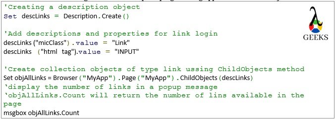
Sample Code 2 - UFT Interview Questions and Answers
Descriptive Programming – UFT Interview Questions and Answers

Q38. What is ChildObjects?

Ans: This method is used in description programming approach. Based on the description, the method ChildObjects returns a list of matched objects. Please refer last question for example.

Q39. What are ChildItem?

Ans: When working with the table objects, the ChildItem method is used to interact with embed objects with in table cell. It will help to perform operations such as click, getRoProperty, etc. The syntax for usage –

testTableObject.ChildItem(row,col,mic_class,index).Click

testTableObject – Indicates a table object.

row – Indicates table row number.

col – Indicates table column number.

mic_class – Refers type of the embedded object like Link, Button, etc.

index – Refers the occurrence of the embedded object. It always starts from zero.

Q40. How can we associate a shared object repository in action?

Ans: Two options are available –

  • Right-click on the node which represents the action name from the UFT solution explorer section.
  • Choose the option “Associate Repository” with Action to open Shared Object Repository dialog box.
  • Now, choose the correct shared object repository file and click Open to associate it.

Q41. Explain the main difference of “call to copy of action” with respect to “call to existing action”?

Ans: 

call to copy of action  – It will copy the entire reusable action into the working test script as local action. So any change in reusable action will not be reflected here.

Call to existing action  – It will link the reusable action from the working test script as local action. So any change in reusable action will be reflected here.

Q42. What is “Object Repository Manager”?

Ans: It’s use to manipulate shared object repository. It allows to add, modify, remove of test objects from the repository. The object repository manager window can be opened from UFT menu –

Resources -> Object Repository Manager.

Q43. What is the purpose of the “Object Repository Comparision Tool”?

Ans: This tool is used for comparison between two tsr files i.e. shared object repositories. After the comparison, it will identify the mismatches. It can be opened from “Object Repository Manager” by the following path – “Tools->Object repository Comparision Tool.”

Q44. What is the purpose of the “Object Repository Merge Tool”?

Ans: This is used to merge two shared object repository into one. It can be opened from “Object Repository Manager” by the following path – “Tools->Object repository Merge Tool.”

Q45. Explains the action parameters?

Ans: The action parameters are acted as arguments for the UFT action. The main purpose of action parameters is to pass the input values to action and receive the output from the action.

It can be configured from the action properties section. Two types of action parameters can be created which are –

Input Parameter – It’s used to pass input data to the action.

Output Parameter – It’s used to receive output data from the action.

Q46. How to pass data using input action parameters?

Ans: The input action parameters value can be passed through input parameters into the child action. Example –

RunAction “childAction“, oneIteration,ipValu1,ipValu2, opValue

Here, input data are passed through the variables ipValu1 and ipValu2 into the child action. The input parameters are paramValue1 and paramValue2. The input parameters can be read from the child action using expressions Parameter(“paramValu1”) and Parameter(“paramValu2”).

Q47. How can we read the value of output parameters from the main action?

Ans: The output action value can be return through output parameters from the child action. Example –

RunAction “childAction“, oneIteration,ipValu1,ipValu2, opValue

Here opValue is the variable that receives the value of output parameter from the child action.

Q48. How can we click on a link available on a webtable?

Ans: We can click on a link available in a webtable using the childitem method. Example –

Set tableObject = Browser(“SampleApp”).Page(“SampleApp”).WebTable(“MyTable”)

tableObject.ChildItem(row_num,col_num,micClass,index).Click

row_num – row number of the table.

col_num –It represents the column index of the table.

micClass – Object type such as Link, Button, etc.

Index – occurrence of the object type in the particular cell. Index value starts with numeric 0.

Q49. What are the different options are available if a particular object is not getting identified by UFT?

Ans: Different available options are –

  • Use of virtual objects.
  • Perform low-level recording, and we can click on based on the co-ordinates.

Q50. Explain the best practices to work with actions?

Ans: The common best practices are –

  • Give a proper action name.
  • Use action parameters to work with dynamic test data that are generated during execution.
  • Use data table or external excel sheets for test data.
  • Use of shared repository instead of local object repository.
  • Use reusable actions for unit functions.

Q51. What are the functions of UFT? 

Ans: Function is a collection of statements to perform specific task. In UFT, we can write any conditional, logical, looping statements in function through vbscripting. Also, we can write scripts with the help of shared objects repository in functions. Functions are written in function libraries, which are stored in external paths. To work with functions, we need to associate the corresponding functional library with our test scripts.

Using a combination of functions and a shared object repository, we can replace our reusable actions.

Q52. What are the differences between UFT functions and UFT actions?

Ans: The differences are –

  • Action has the own local object repository and datatable. But function does not have that.
  • It is not possible to execute the functions as a standalone component which is possible for UFT actions. The function should be use with in actions.
  • The function is easy to maintain in comparison to actions.
  • By using multiple reusable actions, execution performance may be reduced. Execution performance may be increased by using of function library.
  • We can not develop test scripts without using at least one action. But the function library is not an essential component of UFT. 

Q53. What are the environmental variables? Explain the classifications?

Ans: This features is used for test data parameterization in UFT. The test data which are applicable across the entire test suite, are stored in the environment variables such as, application URL, Report Path, Test Environment name, etc. The structure to use environment variables is Environment.Value(“param_name”). It can be viewed from Environment tab which is available in “Test Settings” wizard.

The environment variables in UFT are classified into below two categories –

Built-in: The built-in environment variables are pre-defined by the UFT which are used to keep the tool and test related information such as, TestName, OS, OS Version, etc. This variables are read-only and can be accessible from entire test suites.

User-Defined: The UFT allows us to create environment variables based on the requirement which are known as user-defined environment variables. Again, two types of user-defined environment variables are available which are –

  • Internal – The scope of this types of variables are specific to the individual test cases only. From the Environment tab of setting wizard, the user-defined internal environment variables can be created, modified or deleted. Also, it can be defined during the execution as well with the expression Environment.Value(“param_name”)=”Some value”.
  • External – This kind of user-defined environment variables are defined in a XML file which need to be attached with UFT to access the individual variables. The external variables can be access through out the suite as read-only.
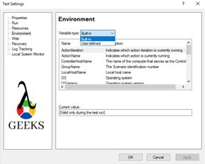
Environment Variables - UFT Interview Questions and Answers
UFT Interview Questions and Answers

Q54. What are the limitations of virtual objects?

Ans: Limitations are –

  • The virtual objects can not be created through recording.
  • It can not be used with Checkpoints.
  • We can not analyze the virtual objects using object Finder.
  • It’s depends on screen resolution.

Q55. What are the limitations of the function library?

Ans: The limitations of a functional library are –

  • The function library does not have an object repository and datatables.
  • Execution of function is not possible from Function library. It should be referred from Actions to execute.
  • The function libraries are the optional component.
  • It works with shared object repository or descriptive programming to develop functional script through funtions.

Q56. What is datatable? Explain the different types of datatables?

Ans: Datatable is one of the most important components of UFT. It’s similar to Microsoft Excel, which is used to store data and feed the same in test scripts. Based on the data available in different rows of datatable, we can execute the test cases in a loop. Read/ Write both the operations are possible during execution.

The UFT datatables are classified into two types –

  • Local datatable – The every action is built with a default datatable, which is know as local datatable. The scope is available through out the test case. The expressions to access any specific parameter item from the datatable –

DataTable.Value(“paramItem1”,dtLocalSheet) or DataTable.Value(“paramItem1”,”SheetName”)

Here, dtLocalSheet indicates the default local datatable available within the action.

  • Global datatable – The every test case is built with a default datatable, which is know as global datatable. The scope is available through out the test case. The expressions to access any specific parameter item from the global datatable –

DataTable.Value(“paramItem”,dtGlobalSheet) or DataTable.Value(“paramItem”,Global)

Q57. Explain the syntax to read or write data in datatables? 

Ans: In this example, we will see how to copy data from one cell to another cell in UFT datatable.

//Set or select the second row of the datatable
DataTable.GetSheet(“mainAction”).SetRowCount(2)
//Copy from Param1 to Param2 using a temp variable
tempVariable = DataTable.value(“Param1”,“mainAction”)
DataTable.value(“Param2”,“mainAction”) = tempVariable
DataTable - UFT Interview Questions and Answers
DataTable – UFT Interview Questions and Answers

Q58. What is an active screen? Explain the purposes.

Ans: The Active Screen pane allows us to view snapshots of test application as it is displayed during recording time.

We can add steps, checkpoint after running the test by right-clicking in the Active, without opening your application. Also, it can be used as a reference for the test object in the future for any test failure.

Q59. What is the recovery scenario? Explain the purposes.

Ans: A recovery scenario is an approach to control any unexpected events or errors which can appear at the run time. The “Recovery Scenario Manager” wizard is used for working with recovery scenarios. The wizard is available in UFT menu option “Resources → Recovery Scenario Manager.”

Through the recovery scenarios, we can handle either of the below-triggering points, which are the root causes of errors –

  • Errors for un-handled pop-up windows.
  • Errors related to Object State
  • Error during Test Run
  • Application Crash

The main purpose of the recovery scenario is to handle all types of unexpected errors and perform some predefined tasks based on the error types.

Q60. How to develop a recovery scenario?

Ans:  We can define recovery scenarios through the Recovery Scenario Manager through the navigation “Resources → Recovery Scenario Manager.” While developing the recovery scenarios, some configurations need to be done through the Recovery Scenario Manager. The configurations are Triggering Event, Recovery operations, and Post-Recovery Test Run Options.

Q61.Which programming language is followed by UFT for scripting?

Ans: VBScripting is used.

Q62. Write the conditional structure in UFT scripting?

Ans: Different Conditions in UFT are –

If-Else Statements: 

If condition then

               //statements for valid conditions

Else

               //statements for invalid conditions

End If

Switch Statements:

Select Case expression

   Case expression 1

      statement

      ….

   Case expression 2

      statement

      ….   

  Case Else

      writ the else statement

      ….

End Select

Q63. Explain the different types of loop structures available in UFT?

Ans: Different looping structures are –

  • For loop
  • Do While loop
  • While Loop
  • Looping based on entries in datatable by configuring the run settings.

Q64. What are the different kinds of application platforms supported by UFT?

Ans: Major UFT Supported application platforms are – SAP, HTML, Delphi, Powerbuilder, Java, dotNet, Oracle Apps, PeopleSoft, WPF, Webservice, VB, Siebel, Mobile Devices, Terminal Emulator, etc.

Q65. What are the prerequisites required to automate SAP application?

Ans: Prerequisites for SAP automation are –

  • Enable scripting parameters through tcode rz11.
  • Enable scripting from Client option settings.

 Q66. How can we import or export excel in datatables?

Ans: Import Excel sheet:

DataTable.ImportSheet excelFile, sourceSheet, destSheet

excelFile – Represents the excel file which is available in external location.

sourceSheet – Represents the name of the excel sheet which will be imported.

destSheet – Represents the datatable name to store the external excel data.

Export Datatable:

DataTable.ExportSheet excelFile, sourceSheet, destSheet

excelFile – Represents the excel file name which which will be created in external location.

sourceSheet – Represents the name of the datatable which will be exported.

destSheet(Optional) – Represents the external excel sheet name.

Q67. What configuration do we need to create to run the test case in a loop based on the entries in datatable?

Ans: Open the test setting window from the navigation “File->Setting” and select the Run tab. In this section, by selecting either “Run all rows” or “Run from row” radio option, we can enable this looping set.

Q68. How can we connect the database and execute select statements?

Ans: Below steps can be useful to work with database –  

‘Create ADODB connection object

Set objConn = CreateObject(“ADODB.Connection”)

‘Create Recordsetobject

Set objRS = CreateObject(“ADODB.Recordset”)

‘Connect to DB using provider and server

objConn.open <connection string for the database>

‘Define SQL Query

sqlQuery=”Select * from student”

‘Execute SQL

objRS.open “Select studentname from student where role=1”, objConnection

‘Display student name

msgbox objRS.fields.item(0)

‘Close connections

objRecordSet.Close

objConn.Close

Set objConn = Nothing

Set objRecordSet = Nothing

Q69. Explain the different approaches to handle synchronization?

Ans: Synchronization issues can be handled by using the below approaches –

  • Synchronization can be handled using Wait(timeout) statement with the hardcoded wait time in seconds. At this point, the script will wait for a specified duration and then move on to the next step. Based on the application performance, we need to provide the timeout value.
  • WaitProperty – In this approach, we need to provide the property name with values for which execution needs to be a wait and the maximum wait times in mili-seconds. Once the specified property is getting satisfied with expected value, the script execution will proceed with the next step. Example –

Window(“Program Manager”).WinListView(“SysListView32”).WaitProperty “visible”,true,10000

  • Also we can use loop to check the appearance of the object to handle the synchronization.

Q70. How to store UFT test cases in ALM?

Ans: Firstly, we need to connect the ALM from UFT through the Connect ALM option. During the connection, we need to provide the ALM Server, Credential, and project details to connect. After the successful full connection, we need to choose the ALM path while saving the test scripts.

Q71. How can we execute UFT test cases from ALM?

Ans: Goto the ALM Test Lab and select the corresponding test cases from the Test Set. By clicking on the Run button to initiate the execution. We can trigger the execution for multiple or entire testset at a time. After initiation, ALM will invoke the UFT in the background and start the execution based on the  selection.
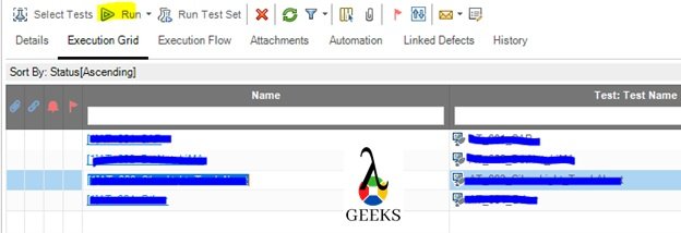
Run From ALM
Run From ALM

Q72. What setting is available to enable remote execution in UFT?

Ans: Open the Options window from navigation “Tools->Options.” In the General tab, we need to select the Run Sessions section to enable a remote execution setting.

Here we need to set the check box and provide valid credentials of the remote test systems.
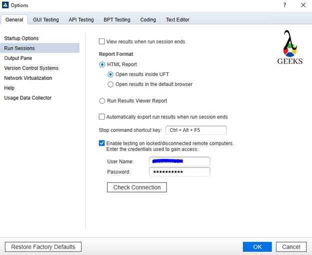
Remote Execution Setting

Few more important UFT Interview Questions and Answers:

Q73. Explain the merits of UFT over Selenium?

Ans: The merits of UFT over Selenium are mentioned below –

· Selenium only supports web applications where UFT supports different platforms such as web, SAP, Windows, Mobile, etc.

· Easy to develop/ maintain test scripts in UFT over Selenium.

· Easy to learn UFT in a shorter span of time.

· End-to-end testing is possible in UFT.

· We can test different application interfaces through web services which is not possible in Selenium.

· UFT saves the costs and efforts, mostly in regression testing over Selenium.

· Easy to embed UFT with ALM for test management. The integration between Selenium and ALM is very difficult.

· Test framework setup is easy for UFT.

Q74. How to invoke web browser in UFT?

Ans: Different ways to invoke web applications are –

·         Using SystemUtil.Run method – The structure of the statements is SystemUtil.Run ( Name_of_File, Arguments, File_Path, action)

· Use of VBScripting Wscript.shell class – 

Dim oShellSet oShell = CreateObject (“Wscript.shell”)

           oShell.run “<Path for browser>”

           Set oShell = Nothing

·  Use of object InternetExplorer.Application – 

            Set obj = CreateObject(“InternetExplorer.Application”)

obj.Navigate https://www.google.com/

            obj.Visible = True

            obj oIE = Nothing

Q75. Explain the approach of the automation recording option?

Ans: It is an approach to generate linear test cases by recording the manual navigation through the UFT. During the recording, the raw test cases are created where data are hardcoded with zero script reusability. It’s useful for one time test execution. It’s not advisable to create the test case for longer run through the recording feature of UFT.

The recording can be initiated by pressing F6 key or clicking on Record button which is available in Record Tab.

Q76. Explain the steps of script debugging?

Ans: Debugging is an approach to identify the script issues through a dummy run. The steps are –

· Create the breakpoint by pressing after the selection of a particular script line from where we need to start the debugging.

· Run the test or start debugging from the first step (Run->Debug from step). Here in the first case, execution will be halted at the breakpoint.

· Now we can debug each code of line by pressing F10(Step Over) or F11(Step into) key. F10 will debug each line in the parent function, but through F11, we can drill down into the sub-functions.

· During the debugging, we can view any variable or state of objects by pressing the “Ctrl+Alt” keys together.

Q77. How to log verification status in UFT reports?

Ans: We can log the verification status using the ReportEvent method. The structure of this method is –

Reporter.ReportEvent status, step_name, details, image_file_name

status – four options are available based on the verification result. micPass, micFail, micWarning, micDone.

step_name – need to provide the actual step name or the expected result.

details – need to provide the actual result.

image_file_name – This is an optional step to provide the screenshot filepath.

Q78. Explain the different types of recording modes in UFT?

Ans: Different recording modes in UFT are mentioned below,

·       Normal mode – The normal mode is the default recording mode available in UFT which uses all the features to identify the test objects. The normal mode is also referred as Contextual, which is applicable only for UFT compatible applications.

·        Low-level recording mode – The low-level recording mode is applicable for applications which are not identified by the UFT. In this mode, scenario is getting recorded based on the co-ordinates of the test objects.

· Analog Recording – Analog recording mode records the movement of mouse and keyboard actions..

Q79. Explain the concepts of a logical name for any object?

Ans: Logical name is defined by the UFT while adding or recording to map any object with the application name. It can be modified based on user object behavior. 

Q80. Specify the extension of UFT script?

Ans: The UFT scripts are created with .mts extension.

Conclusion:

Expecting this UFT interview questions and answers will definitely help to clear the UFT interviews.

 We wish you all success!!

9 Facts On Rheostat:What,Symbol,Types,Applications

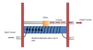
General Structure of a Linear Rheostat 300x162 1

What is a rheostat

To define a rheostat, we need to know what is Resistor or Resistance. Resistors are electrical devices that are to controls the flow of current.  A formal rheostat’s definition will be –

Rheostat is an element of an electrical circuit whose resistance value can be changed whenever needed, that means a variable resistor.”

It is a three-terminal device, of which two are usable. There is a slider as a moving terminal, and only one is usable out of two fixed terminals. A typical rheostat also consists of a resistive material and a slider.

What does a rheostat do

The basic principle of this device is simple. In electrical circuits, whenever we need to change the resistance value, a rheostat comes into action. If we need to increase the flow of current – we will increase the resistance of the device. When we need to decrease the current flow in the circuit, we will raise the resistance value. 

How does a rheostat work

Rheostat works on the property of resistance. The resistance of a material (let’s say wire) depends linearly with the length and inversely with the cross-section area.

R∝L/A

R=?L/A,

?is the resistivity of the material

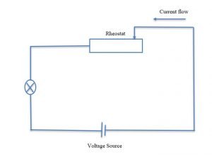
Thus, if we keep the cross-section area constant, increasing the length will increase the resistance. As shown in the figure, the slider- is moved through the resistive element for linear rheostats. It moves either from input to output or vice-versa. The effective length changes accordingly. While moving the wiper towards the output port, the effective length decreases, causing a fall in resistance, increasing the current.

Rheostat connection
Working of a Rheostat

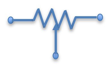
Rheostat symbol

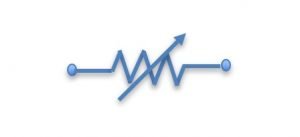
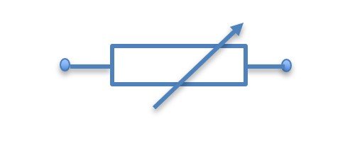
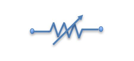
Institute of Electrical and Electronics Engineers(IEEE) and the International Electrotechnical Commission(IEC), has defined two different rheostat’s symbols.

Symbol of rheostat
The IEEE standard Rheostat symbol
Symbol of rheostat
The IEC standard Rheostat symbol

Rheostat Switch

Rheostats control current of a circuit by controlling the resistance of the circuit. A rheostat, thus, can be used as as switch to vary the resistance as well as the current of the circuit. That is why a rheostat is used as switch.

Rheostats Applications

A rheostat has its application in an electrical circuit.  When there’s a need to control the flow of current with a change of time. Based on the property of current controlling, some of the purpose of rheostat is given below.

Why is a rheostat connected in series?

To connect rheostat in the circuit, we must place it in series, not in parallel. The flow of current is much in a lesser resistive path. Thus, when it finds an option between a less resistive path and a more resistive path, it always chooses the lesser one.

Now, a rheostat is a device that has some variable resistance value. If we connect it to the parallel path, that path gains some more resistance than the other way available. When current flows in the circuit, electrons will never choose the parallel-path instead- they will flow straight through the series path. So, the rheostat will not function at all. It needs the current flow to work as a rheostat. 

Rheostat connection
Series Connection

Type of Rheostat

Though there are several types of rheostat available, three main types are – 

  • Linear Rheostats
  • Rotary Rheostats
  • Preset Rheostats

A. Linear Rheostats:

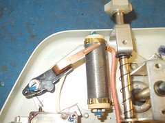
This type of rheostat consists of a cylindrical resistive element. The slider is moved linearly along the resistive element. It has two fixed terminals; one- is used, and another connects the slider. This type of rheostats is mostly used  – in laboratories and experiment purposes.

37109063556 585fed013f m
Linear Rheostats ; source –
Rheostat” (CC BY 2.0) by tony_duell

B. Rotary Rheostats:

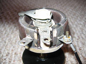
This type of rheostat has a resistive element, which is circular. To use it, one needs to move the slider in a rotary way. They find applications in power electronics and also, they are used widely because of their smaller size than linear types. As the wiper needs to rotate to change the value, that’s why it is called a rotary rheostat.

300px Pot1
Iamge Credit: Gdead at English WikipediaPot1, marked as public domain, more details on Wikimedia Commons

C. Preset Rheostats:

When it is needed to implement a rheostat in a PCB (Printed Circuit Board), one should use preset rheostats or trimmers. It provides fine-tuning, that’s why they have found application in calibration circuits. This types of rheostats are suitable for industrial uses.

Differences between rheostat and potentiometer

There is a misconception that a rheostats and potentiometer are the same things, but there are some differences. Let us discuss some of them –

Subject of ComparisonRheostatsPotentiometers
Number of TerminalsTwo terminal deviceThree terminal device
Connection in CircuitSeries connectionParallel connection
Quantity ControlledControls CurrentControls Voltage
ApplicationHigh power applicationLow power application
Number of TurnsSingle turn Both single and multi-turn
Resistive materialCarbon disk, Constantan, Platinum, etcMaterials like Graphite
    SymbolThe IEEE standard Rheostat 1Potentiometer

Know more about Potentiometer – Click Here!

Frequently asked questions on Rheostats

1. How are rheostats rated?

Rheostats are rated – in Amperes and Watts. There is also a resistance value. For example – 50W – 0.15 A, 100k Ohm. It means the maximum amount of current that can be measured is 0.15A. The resistance offered by the rheostat will be in the range of 0 to 100k Ohm.

2. How to select a rheostat based on rating?

While selecting a rheostat, the current rating is more important than the power rating.

It is the current that limits what power the device will generate provided for any resistance value. One should select rheostats with a current rating more than or equal to the actual need of current in the circuit.

3. What are the differences between resistors and rheostats?

A resistor is a passive electronic component that reduces the flow of current by providing resistance. On the other hand, rheostats are – variable resistors, which gives different values of resistances as per the need.

4. What is the function of a rheostat in the circuit?

  • A. It decreases the current
  • B. It increases the current
  • C. It limits the current
  • D. It makes the current constant in the circuit
  • E. All of the above

The correct option will be E. All of the above. Using Ohm’s law, we can find the answer to the question. As the ohm law states, V = IR, where V is the applied voltage, I is current, and R is the resistance. Rheostat provides variable resistances value; thus, it can increase, decrease, and limits the current. Keeping the resistance value constant will keep the current steady. So, all the options are correct.

5. Can rheostats be used as a potentiometer?

The answer is no, but there is some way to do this. A rheostat is a two-terminal device, while a potentiometer is a three-terminal device, so it seems impossible. But if a rheostat has inbuilt three terminals, the unused terminal can be joined to the circuit to use it as a potentiometer.

6. Can potentiometers be used as a rheostat?

Yes, a potentiometer is usable as a rheostat. A potentiometer controls voltage in a circuit. A potentiometer has three terminals. One terminal should connect the wiper while another should leave unconnected.

7. What are the drawbacks of using a rheostat?

There are few drawbacks of using this device. Some of them are –

A. The main drawback of this device is that it produces excessive heat causing loss of power.

B. It is bigger & does not fit into modern devices. That’s why rheostats are not used – in modern technologies. Though in rotors and various laboratory experiments, they are irreplaceable. Some of the replacements of rheostats are – triacs, SRCs, etc.

8. What type of taper a rheostat has?

Rheostat has linear types of taper. A taper is a relationship between resistance and sliding position. It is one of the most important parts of the device.

9. What is the use of a rheostat in a Wheatstone Bridge?

A Wheatstone bridge is used in labs to measure mean value resistances. Rheostats find its application in a Wheatstone Bridge to determine the value of unknown resistance in imbalanced conditions. The maximum resistance a rheostat can offer is the maximum resistance that a mounted Wheatstone Bridge can measure.

10. Why is choke of a coil preferred over a rheostat in AC circuits? 

A rheostat is a resistive element. It provides resistance and produces an excessive amount of heat. So it causes a loss of electricity. On the other hand, a choke coil is an inductive element by nature. It maintains the same power but changes voltage according to Faraday’s Law. That is why a choke coil is preferred more.

11. Does a Rheostat change voltage?

No, a rheostat doesn’t change the voltage of the circuit. One of the conditions for working of a Rheostat is to keep the voltage constant. As the Ohm’s law states- V= IR, where V is the voltage, I is current, R is resistance. Using a rheostat, we change the current. One of the conditions for working of a Rheostat is to keep the voltage constant. Then only it can change the current of the circuit.

12. Does a rheostat’s terminal have polarity?

A rheostat is a three-terminal device of which two are fixed, and one is a moving terminal. The terminals have no polarity. So, any terminal can be connected.

Cover Photo By: Pinterest

Keratometer: The Two Important Types and Steps to Use

keratometer 2 important types steps to use

Summary

Keratometers are essential instruments used in ophthalmology to measure the curvature of the cornea, which is a crucial factor in determining the refractive power of the eye. The two important types of keratometers are manual keratometers and automated keratometers. Manual keratometers use movable mires or prisms to assess corneal curvature, while automated keratometers employ photosensors to measure the same. Both types provide valuable data, such as the flat and steep meridians of the cornea, the keratometric difference, and additional measurements like the axis of astigmatism and corneal thickness. Understanding the proper steps to use these instruments is crucial for accurate and reliable keratometry measurements.

Manual Keratometers: Principles and Procedures

keratometer 2 important types steps to use

Principles of Manual Keratometers

Manual keratometers, also known as manual ophthalmometers, operate on the principle of reflection. They use a series of movable mires or prisms to assess the curvature of the cornea. The cornea acts as a convex mirror, reflecting the mires or prisms onto the retina. By analyzing the size and position of these reflected images, the instrument can determine the radius of curvature of the cornea.

The key components of a manual keratometer include:

  1. Mires or Prisms: These are the movable elements that project a pattern of light onto the cornea. The reflected pattern is then observed and measured.
  2. Focusing Mechanism: This allows the user to adjust the focus of the instrument to ensure a clear and sharp image of the reflected mires or prisms.
  3. Measurement Scales: The instrument is equipped with scales that provide readings in diopters (D) for the flat (K1) and steep (K2) meridians of the cornea.

Procedure for Using a Manual Keratometer

  1. Patient Positioning: The patient should be seated comfortably, with their chin resting on the chin rest and their forehead against the forehead rest of the keratometer.
  2. Instrument Alignment: The examiner should align the keratometer with the patient’s eye, ensuring that the mires or prisms are centered on the cornea.
  3. Focusing: The examiner should adjust the focusing mechanism of the keratometer until the reflected mires or prisms are sharp and clear.
  4. Measurement: The examiner should read the measurements for the flat (K1) and steep (K2) meridians of the cornea from the instrument’s scales. The difference between these two readings is known as the keratometric difference or K-difference.
  5. Astigmatism Measurement: The keratometer can also provide information about the axis of astigmatism, which is the orientation of the steep and flat meridians of the cornea.

It is important to note that manual keratometers require a certain level of skill and experience to use effectively, as the examiner must be able to properly align the instrument and interpret the reflected mire or prism patterns.

Automated Keratometers: Principles and Procedures

Principles of Automated Keratometers

Automated keratometers, on the other hand, use advanced technology to measure corneal curvature. These devices employ photosensors to capture images of the cornea and specialized software to analyze the data. The software compares the patient’s corneal measurements with a standard value database to provide accurate and objective readings.

The key components of an automated keratometer include:

  1. Photosensors: These are specialized sensors that capture high-resolution images of the cornea.
  2. Software: The software analyzes the captured images and provides measurements of the corneal curvature, as well as other parameters such as the axis of astigmatism and corneal thickness.
  3. User Interface: Automated keratometers typically have a user-friendly interface that allows the examiner to input patient information, initiate the measurement process, and view the results.

Procedure for Using an Automated Keratometer

  1. Patient Positioning: The patient should be seated comfortably, with their chin resting on the chin rest and their forehead against the forehead rest of the keratometer.
  2. Instrument Alignment: The examiner should align the keratometer with the patient’s eye, ensuring that the photosensors are properly positioned to capture the corneal image.
  3. Measurement: The examiner should initiate the measurement process, which typically involves the keratometer automatically capturing one or more images of the cornea.
  4. Data Analysis: The software within the automated keratometer will analyze the captured images and provide the measurements for the flat (K1) and steep (K2) meridians of the cornea, as well as other parameters such as the axis of astigmatism and corneal thickness.
  5. Result Interpretation: The examiner should review the results displayed on the user interface and interpret the data, taking into account any potential sources of error or variability.

Automated keratometers are generally more user-friendly and provide more accurate and consistent measurements compared to manual keratometers. However, it is still important for the examiner to understand the principles of keratometry and the potential sources of error to ensure accurate and reliable measurements.

Comparison of Manual and Automated Keratometers

Feature Manual Keratometers Automated Keratometers
Measurement Principle Reflection of mires or prisms Photosensor-based image capture and analysis
Measurement Accuracy Dependent on examiner skill and experience Generally more accurate and consistent
Measurement Parameters Flat (K1) and steep (K2) meridians, K-difference Flat (K1) and steep (K2) meridians, K-difference, axis of astigmatism, corneal thickness
User Interaction Requires manual alignment, focusing, and reading of scales Automated measurement process with user-friendly interface
Portability Typically more portable and compact May be larger and less portable
Cost Generally less expensive Typically more expensive

Sources of Error and Considerations in Keratometry

Keratometry measurements can be subject to various sources of error, which can affect the accuracy and reliability of the results. Some of the key considerations include:

  1. Instrument Alignment: Proper alignment of the keratometer with the patient’s eye is crucial. Misalignment can lead to inaccurate measurements.
  2. Eye Movement: Patient eye movement during the measurement process can introduce errors. Proper patient positioning and instructions are essential.
  3. Tear Film Variations: Changes in the tear film can affect the reflective properties of the cornea, leading to variations in measurements.
  4. Corneal Irregularities: Conditions such as keratoconus or corneal scarring can cause irregular corneal curvature, which may not be accurately captured by the keratometer.
  5. Instrument Calibration: Regular calibration of the keratometer is necessary to ensure accurate and consistent measurements.

To minimize these sources of error, it is important to follow proper measurement protocols, ensure proper patient positioning, and regularly maintain and calibrate the keratometer.

Conclusion

Keratometers, both manual and automated, are essential instruments in ophthalmology for measuring the curvature of the cornea. Understanding the principles and procedures for using these devices is crucial for obtaining accurate and reliable keratometry measurements. By familiarizing themselves with the two important types of keratometers and the steps involved in their use, healthcare professionals can provide better diagnostic and treatment services to their patients.

References

  1. Eye Patient. (n.d.). Keratometry Test. Retrieved from https://eyepatient.net/Home/articledetail/keratometry-test-413
  2. SlideShare. (2014, February 20). keratometry | PPT – SlideShare. Retrieved from https://www.slideshare.net/slideshow/keratometry-31466440/31466440
  3. NCBI Bookshelf. (n.d.). Keratometer. Retrieved from https://www.ncbi.nlm.nih.gov/books/NBK580516/
  4. ScienceDirect Topics. (n.d.). Keratometer – an overview. Retrieved from https://www.sciencedirect.com/topics/nursing-and-health-professions/keratometer
  5. ScienceDirect Topics. (n.d.). Keratometer – an overview. Retrieved from https://www.sciencedirect.com/topics/medicine-and-dentistry/keratometer

Tosca Test Case:Design And HandsOn Comprehensive Guide !

Test Case Design Objects

Tosca Tutorial – Table of Content

We have broken the entire Tosca tutorial into the below list of articles. Now we are going to understand about the concepts of Tosca Test Case Design and Test Data management through out this tutorial. We have wrote this article with simple words and keep the write up shorts which help the new comer to understand the concept easily with lesser time.

In this Tosca Test Case Design and Test data Management article, we will learn about the step by step implementation approach of Tosca Test Case Design and overview of Test Data Management. If you want to prepare for TOSCA Interview Questions, please click here.

Tosca Test Case Design (TCD)

This is an approach to isolate the test data from the technical sections of test cases. So, the data and test cases are kept separately. The Tosca Test Case Design section has the capability to break our test cases into a logical structure. It is also help us to plan and design the testcases in a efficient and structured way to reduce the development and maintenance efforts.

Use the Tosca Test Case Design section is performing the below activities – 

  • Create the testsheets, which is a combination of all possible test cases for any particular scenario or template. Basically, testsheets are holding the data for different combinations.
  • The concept of class in test case design approach, helps to reuse the common data across the test cases which reduce the efforts of data management.
  • With the help of instances, we can create the specific data for TestSheets, TCD Attributes, or TCD classes.
  • Create TestCase Templates and assign the Testsheets.
  • We need to instantiate or re-instantiate Templates to generate the instance test cases as per the testsheets.
  • Manage test data in testsheets and execute the instance test cases

Test Case Design objects:

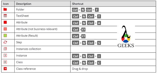
The table below lists all components available in the Test Case Design section, and keyboard shortcuts where applicable.

Test Case Design - Objects
Objects of Test Case Design
  • Folder – The test case design folder is used to group the test sheets or classes in a logical way.
  • TestSheet – TestSheet is a list of data for all possible combinations of Tosca test cases. Each data set represents one unique test case.
  • Attribute – It’s referred to as the different data parameters corresponding to each application field.
  • Attribute(not business-relevant) – It’s used for comment or description purposes.
  • Attribute(result) – It’s used for result purposes.
  • Instances Collection – It holds the Instances i.e., all possible values available for particular attribute.
  • Instances – This is the value of each attribute/parameter. It can be created TestSheets, Attributes, or Class level. Instances of Testsheets are basically a test case name.
  • Class – This is similar to testsheets, but it’s used for the reusable purpose. All the common data are stored here, which can be reused in multiple testsheets.
  • Class reference – It’s acting as a link of Classes from Testsheets. We can create it with the drag-drop method.

Object hierarchies in Test Case Design:

  • A TestSheet may have Attributes, Instances, TestSteps, and class references.
  • A class may be the combinations of class Attributes and Instances.
  • Again, an Attribute can keeps further Attributes and Instances.
  • A Step can keeps more Steps and Attributes.

Step-by-step process to implement Test Case Design:

  • Step1: Create the Class if there is some common sections are available for multiple test cases. For example, Login is a common section in most of the application. So, we need to create a class as per the below diagram –
Test Case Design - Define Class
Test Case Design – Define Class
  • Step2: Create testsheets as per the below structure and link the classes. Testsheets are used for the unique individual scenario. Based on the different data combinations, different test cases will be generated as per the instances of testsheets.
Test Case Design - Refer Class from TestSheet
Test Case Design – Refer Class from TestSheet
  • Step3: Create template test cases. We can convert any existing technical test case into a template test case by selecting “the Convert to Template Testcase” option after right-clicking on it.
  • Step4: Assign the testsheet into the template test case by drag and dropping the testsheet into the template test case. Only one testsheet can be assigned to one template. After this, we can assign the Test Case Design data Attributes/ parameters into the test steps by drag-drop method or typing. Syntax for linking the parameters – {XL[parameter_name]}. The template test case can not be executed.
Test Case Design - Create Template
Test Case Design – Create Template
  • Step5: After assigning the data parameters, we need to generate the instance test cases. It can be done by opting the option Instantiate or Re-instantiate by right-clicking on template test cases. After the, all the possible test cases will be generated based on the data combinations of test sheets.
Test Case Design - Create Instances
Test Case Design – Create Instances
  • Step6: Now, we can create an execution list to execute the instance test cases.

Advantages to TCD:

  • · Dynamic handling of objects/data is easy
  • · Reusability of test cases
  • · No scripting involved
  • · Data and technical components are kept separately. In the case of data change, no need to modify the test cases.

Disadvantages of TCD:

  • · Test case design section is very complicated
  • · A little expensive
  • · The UI takes time to understand

Reference Link – https://documentation.tricentis.com/tosca/1300/en/content/testcase_design/testcase_design_intro.htm

Tosca Test Data Management (TDM)

Test Data Management is an approach to manage the required test data for test execution. It will help us to use the data which are stored externally. 

Test Data Management - Overview
Overview of Tosca Test Data Management
  • Test data management is an another important component for data management which is available along with the standard installation of Tricentis Tosca Test suite.
  • DB2, MS SQL Server and Oracle repositories – Tosca test data management (TDM) component uses the same database which is used to create the common repository of the workspace.
  • SQLite repositories – For SQLite, TDM uses the separate repository to store the data.
  • After creation of a new workspace, by default Tosca is getting connected with the repository.
  • If required, Tosca is able to connect different database as TDM repository instead of default database.

Connecting to a TDM repository: Create Configuration parameter as TDMConnection in the root level and assign connection string in below format -<Databasetype>(<ConnectionString>)[dynamicmode=<on or off>,schema=<Schemaname>]

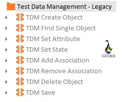
Standard module to handle TDM:

The standard module path – “Standard modules->Test Data Management->Test Data Management – Legacy.” 

  • TDM Create Object – The TDM Create Object module helps to create a fresh TDM object for a specific object type. Initially, the new TDM object can be created with empty value.
  • TDM Find Single Object – It is used to search for a TDM object within the TDM repository.
  • TDM Set Attribute – Set Attribute module is able to set the values for any existing TDM object.
  • TDM Set State – This module is able to set the values of state for any existing TDM object.
  • TDM Add Association – This module is used to define an association between two TDM objects. This association receives an individual role name which allows the mapping.
  • TDM Remove Association – This module is used to remove the association between TDM objects.
  • TDM Delete Object – This module is used to delete the TDM Objects from the TDM repositories.
  • TDM Save – This Module saves the TDM object in the TDM repository.
Test Data Management - Standard Modules
Test Data Management – Standard Modules

Click here to learn more on Test Data Management.

Conclusion:

In this Tosca Test Case Design and Test data Management article, we have learned about Test Case Design and Test Data Management. Click here to understand more from the Tricentis Support portal on this topic.

Please click to read the most important topic of TOSCA Tutorial – Understanding of Tosca Case Creation.

Band Stop Filter:31 Facts That Most Beginner’s Don’t Know!

image 1

Band Stop Filer Definition

Band reject filter is combined of low pass and high pass filter which eliminates frequencies or stop a particular band of frequencies.”

Band rejection is obtained by the parallel connection of a high pass section with a low pass section. Now, the general rule is that, the cutoff frequency should be higher than the cut-off frequency of the low-pass area.

There is another way to create it. If a multiple feedback system is incorporated with an adder, then that functions like the desired operation. It is called as notch.

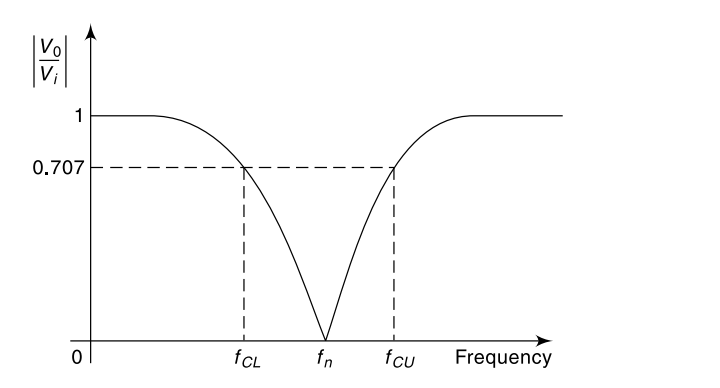
The Frequency response of a bandstop filter is calculated by considering the frequency and gain.


The bandwidth is chosen through the lesser and greater cut-off frequency. Notch filter is used to remove the single frequency. From this frequency response, we can also obtain Passband ripple and stopband ripple.

                                 Pass Band Ripple= -20log10(1-∂p) dB

                                 Stop Band Ripple= -20log1o(s) dB

Where ∂p= magnitude response of the passband filter

             ∂s= magnitude response of the stopband filter

band stop filter
 The frequency response of a band-stop filter 

Why It is called band stop filter ?

Bandstop filter rejects a certain band of frequency and allows another frequency component of the primary signal. If the band of the frequency is narrow, the stopband filter is known as Notch Filter. The filter attenuates the specific band. The filter has several applications.

For example, a band-stop filter is designed to reject frequencies between 2.5 GHz to 3.5 GHz. The filter will allow frequency components lower than 2.5 GHz and above 3.5 GHz.  The filter will We will explore the filter in the below sections.

Passband and stopband of a filter

Before diving into a band-reject or bandpass details, let us understand what pass band and stop band means. A passband is the frequency bandwidth that is allowed by a filter. On the other hand, a stopband is the band of frequency which one filter hasn’t allowed to pass. For a bandstop filter, there are two passbands and one stopband.

What does a band-stop filter do?

As the name suggests, a band-stop filter simply ‘stops band.’ That means a band-stop filter resistor doesn’t allow a certain band of frequency to pass through the

What is a band-stop filter used for

When there is a need to attenuate a certain band of frequency and pass other frequency components, a band-stop filter is used. Bandstop filters are useful in various applications.

Band stop filter applications

Being a very important type of filter, bandstop filters has several applications. Let us find out some of the applications.

  1. Medical Engineering: Bandstop filters are used in medical engineering. Like – in ECG machine. 60 Hz bandstop filters are used to remove the supply frequency from the output.
  2. Audio Engineering: Bandstop filters have huge applications in audio engineering. They remove the unwanted spikes and noises from the score and provides a good quality of audio.
  3. Telecommunication: Bandstop filters are used in telephonic connections to remove the internal noise from the lines.
  4. Radio communication: Band rejects filters are widely used in radio stations to transmit a better audio quality.
  5. Optical filters: Band-stop filters are used to block certain wavelengths of light in an optical communication system.
  6. Digital Image Processing: Bandstop filters are also used in digital image processing to remove certain periodic noises.
  7. Miscellaneous: Whenever there is a need to remove the noise of a certain frequency, a band-stop filter is used.

Band stop filter diagram

This article explains the bandstop filter with various circuit diagrams, block diagrams, and graphs. This article includes a block diagram, band reject-with op-amp, frequency response of band stop, passive circuits, bode plots.

Circuit diagram of band-stop filter

The bandstop filter can be designed in several ways. It can be active types (which has op-amp). It can be for passive kinds (without op-amp). Active types have several varieties, too as well as passive filters have different styles too. That is why there are several circuits available also. In this article, almost all possible courses are given below. Check out the needed one.

Band stop filter block diagram

The bandstop filter is a combination of both high pass filters as well as low pass filters and another amplification factor for the filter. The block diagram is given below.

image 1

Narrow band stop filter

If the freq. of the bandstop filter is narrowed than general, the filter is often known as a Notch filter(hyperlink) or narrow bandstop filter.

Simple band stop filter

Unlike notch filter or higher-order filters, the simple bandstop filter is a basic filter which attenuates certain band of frequency allowing other bands.

Band stop filter using op-amp

Active bandstop filters are designed using operational amplifiers. Op-amp is one of the most important devices in making a filter. In passive filters, as there is no op-amp, there is no amplification. Thus, using the op-amp as a circuit element gives amplification.

Bandstop filter circuit using op-amp

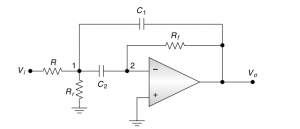
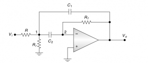
This filter consists of a high-pass filter, a low-pass filter, and a summing amplifier to summation the lpf and hpf’s o/p, The circuit is shown below.

image 2

Band pass filter vs Band stop filter

There are fundamental differences between bandpass and bandstop filter.

The main principle of a bandpass filter is that it allows a certain band of frequency. At the same time, the main tenet of the bandstop filter is that it blocks a certain band of frequency.

Let us take an example to demonstrate. Let us say there is a lower cutoff frequency of Flow and a higher cutoff frequency high. Now, for a bandpass filter, the frequency in between the lower cutoff and higher cutoff will only pass, and other components below the Flow and above the fhigh will not pass.

Now, for a band-stop filter, the frequency band lower Flow, and above fhigh will pass. But the band in between the frequency limit will not pass.

Band stop filter vs notch filter

A notch filter is one type of bandstop filter. The main difference between them is that a notch filter attenuates a narrower band of frequency than a bandstop filter. In other words, bandstop filters have a wider band of frequency to attenuate.

Band stop filter RLC circuit

The band stop filter can be designed using basic components like resistor, capacitor, and inductor. There are two ways of developing the filter – 1. RLC parallel band-reject filter or Parallel resonant band-reject filter, & 2. RLC series resonant band-reject filter. As we are using passive elements, so both the filters will be of passive types.

Parallel RLC band stop filter

As mentioned earlier, a bandstop filter can be designed with basic components like – resistor, capacitor, and inductor. There are two ways of developing the circuits. The methods are discussed below.

Parallel RLC band stop filter 

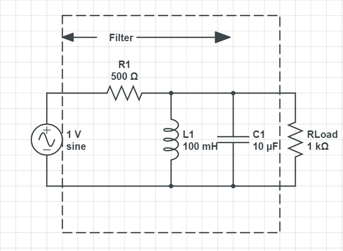
A Parallel RLC bandstop filter is a tank circuit. It also works fine as a frequency attenuator as the tank circuit is providing a lot of impedance. The below image shows the circuit diagram of a parallel rlc bandstop filter.

Parallel Band Stop

The parallel resonant band stop filter 

The parallel resonant bandstop filter is also known as the parallel rlc bandstop filter. The details of the circuit and filter are given previously.

Series resonant bandstop filter 

The main instruments for this filter are – capacitor and inductor. As the name suggests, the inductor and capacitor are kept in series. This part is the filter. At resonance, the circuit can attenuate certain frequencies before reaching the load. The below image shows the circuit diagram of the series resonant circuit.

image 3

Passive bandstop filter circuit 

The passive bandstop filter is made of passive components, such as – resistor, inductor, and capacitor etc. Previously given circuits are an example of such filters. These filters do not have any operational amplifiers. Thus, there is no amplification process. A passive band stop filter consists of both passive hpf and passive lpf.

Active band stop filter

Unlike passive bandstop filters, active band-reject filters come with active components. The most important active part is the operational amplifier which also introduces amplification. Circuit using op-amp or the functional bandstop filter diagrams are given previously in this article.

Active bandstop filter design 

Let us design a band stop filter. The center frequency will be 2 KHz.  The bandwidth will be -3 dB of 200 Hz. Take capacitor value as one uF.

So, fN = 2000 Hz, BW = 200 Hz, C = 1 uF.

At first calculate the R. R = 1 / 4πfN C,

R = 39.78 ohm.

The Quality factor: Q = fN / BW = 2000/200 = 10

The value of feedback function: K = 1 – (1/ 4Q)

Or, K = 1 – (1/40)

Or, K = 0.975

Let us find out the value of resistors.

K = R4 / (R3 + R4)

The R4 value is assumed as 20 kΩ.

R3 comes as: R3 = R4 – 0.975 R4 = 20000 – 0.975 * 20000 = 500 Ω

The notch depth is: 1/Q = 1/10 = 0.1

The depth in decibel comes as: 20log (0.1) = -20 db.

Band stop filter transfer function

The transfer function of a device refers to a mathematical function that provides output for every input. The transfer function of a band-stop filter is given below.

one

The second-order band-stop filter transfer function

The transfer function expression for the second-order band-stop filter transfer function is given below.

two

 Band stop filter graph

The phase response stands for the phase output of the bandstop filter, bottom one represented the phase response.

image 5

Credit: InductiveloadBand-Reject Filter Response, marked as public domain, more details on Wikimedia Commons

Band stop filter bandwidth 

The bandwidth of the bandstop filter depends on the requirement. The band-width is the range of freq. in which the filter will attenuate. In general, the bandwidth is referred to as the specification of a filter.

The impulse response of band-stop filter

Bandstop or band-reject filter can be designed digitally. There are two types of digital band-reject filters, They are – Infinite Impulse Response(IIR) and Finite Impulse Response(FIR). FIR method is more popular.

There are two design methods of FIR filter. They are also known as non-recursive filters. The methods are – 1. Window method & 2. Weighted-Chebyshev method.

Sallen key band stop filter

Low pass filters allow the lower frequency components of a filter and reject the higher frequency components. So, for the low pass filter, the stopband is the high-frequency component.

Sallen key is another topology of designing filters. The bandstop filter can also be created using the topology.  Sallen key topology is designed using operational amplifiers for creating higher-order filters. Thus, we can understand this topology is for active filters. 

Basic Sallen Key topology comes with one non-inverting op-amp and two resisters. It creates a Voltage Control Voltage Source or VCVS circuit. The circuit provides high input impedance and low output impedance which useful for filter analogy.

This Sallen Key topology also provides good stability of the system, which is highly suggested. The circuit is also very simple. They are connected one after another to achieve the higher-order filters. The circuit diagram of the band-reject filter using Sallen key topology is given below.

image 6

Band stop filter formula

There are some important equations for designing a band stop filter. Using these equations, we can find out important parameters. But one of the values of the parameter should be supplied as it is needed to design the filter.

The Normal Frequency Equation:

three

The Lower Frequency Cut-off:

four 1

The Higher Frequency Cutoff:

five

Here, the RL is lower resistance, and RH is higher resistance.

  • The center frequency:
  • The bandwidth: fBW = fH – fL
  • The Q Factor of the filter: Q = fC/fBW

Band stop filter example

The bandstop filter is an important concept that has several applications. That is why there are several examples as well. There is a band stop filter for blocking certain frequencies. Like – 2.4 GHz Band Stop filter. There is a band-reject filter for blocking narrower frequency bands, like the Notch filter, which has several applications. Audio bandstop filters, optical band-reject filters, digital-analog filters are some of its examples.

60 Hz band stop filter

From the filter’s name, we can understand that this bandstop filter is designed for attenuate frequency bands of 60 Hz. Now, the question comes why the 60 Hz band reject filter is so popular. It is because, in the USA, their supply frequency is 60 Hz. So, in most cases, when there is an interference of the supply frequency with the working signal, a 60 Hz bandstop filter is used to remove the frequency band from the output.

Band stop filter bode plot

At first, let us understand what the abode plot means. Abode plot refers to the graph of the frequency response of a device. The freq. response of the band-reject filter is presented below.

image 7

Credit: Michael FreyPassive Band-stop filter Bode Plot, marked as public domain, more details on Wikimedia Commons

Cutoff frequency of band-stop filter

The cutoff frequency of a band-reject filter refers to the frequency of the band to be attenuated. There are formulas for lower frequency cutoff and higher frequency cutoff.

The lower cutoff frequency: fL = 1 / 2π RL C

The higher cutoff frequency: fH = 1 / 2π RH C

Band stop filter image processing

The bandstop filter is used in image processing. There are some different kinds of noises. The noises are repetitive. They have certain frequencies. A band-stop filter omits such noises. At first, the frequency is matched with the noise frequency. Then the bandstop filter removes the noises and makes the image a better one.

Band stop filter pole-zero plot

A band-reject filter can be designed using two zeros placed at ±jω0. These types of designs don’t have a unity gain at zero frequency. A notch filter can be developed by putting two poles close to the zeros.

Bandstop filter using op-amp 741

As mentioned earlier, band-reject filters can be designed using operational amplifiers. That is known as creating active band-reject filters. The band-reject filters consist of both low pass and high pass filters. Both these filters require operational amplifiers to design. Op-amp 741 is used here. Another summing op-amp is also necessary to sum the outputs of the previous filters and provide amplification. Op-amp 741 can be used in all those cases.

Band stop notch filter

A bandstop notch filter is just a special type of band-reject filter. Bandstop notch filter has a narrower bandwidth than usual band-reject filters. To know more about the notch filter, check out my article on Notch filter.

Band stop vs. Bandpass filter

 The name of both the filters explains the difference between them. Here band means the range of frequency. Bandpass filter allows the specific band to pass through the filter and attenuates other components. At the same time, band-reject filters attenuate the particular band of frequency while it will enable other parts.

Characteristics of band stop filter

The bandstop filter has several characteristics. Some of them are listed below.

  1. It has two passbands and one stopband.
  2. It comes with a combination of lpf and a hpf.
  3. If the bandstop filter has a narrow bandwidth, it is a notch filter that has great depth.
  4. Bandstop filters are also known as band-reject filters as it ‘rejects’ the specified band.

Constant k band stop filter

Constant k filter is another topology of designing a filter. It is quite a simple topology, but it has a shortcoming. Here, the ‘k’ is referred to as the impedance level of the filter. It is also known as the nominal impedance. The terminating resistance is also considered as ‘k’ ohms (Rk2 = k2). The bandstop filter using constant k topology is shown below.

image 8

Design Procedure: At first, the center frequency, the bandwidth, and the intended characteristic impedance should be specified. Then follow the steps.

  1. Calculate C2 using wH -wL = RkC2w02/2.
  2. Calculate L2 using L2 = 1/w02C2.
  3. Calculate L1 using L1 = k2C2, as L1/C2= k2.
  4. Calculate C1 using C1 = 1/w02L1.

FIR band stop filter

FIR or Finite Impulse Response Filter is a digital bandstop filter. The formula for an FIR bandstop filter is given below.

image 10

N signifies the dimension of the filter. F1 and F0 are the cut off freq and Fs is the sampling freq.

lC band stop filter

A passive band-reject filter can be designed with an LC circuit. The working of the LC filter is quite simple. Inductors come with a reactance as well as capacitors also come with capacitive reactance. Now an increase in the frequency causes the decrease in capacitive reactance and increase in inductive reactance. This is the primary principle behind LC bandstop filter.

seven
nine

Notch band stop filter

As mentioned earlier, the notch bandstop filter is a normal bandstop filter that has a narrower bandwidth. It has several applications as it has great depth and performance than a band-reject filter. To know more about notch band-reject filters, check here. <link>.

Optical band stop filter

Optical band-reject filters block a certain wavelength of light and allow other components to pass. Just like normal band-reject filters, an optical filter rejects a certain wavelength. For example, there is a 532nm optical bandstop filter. Now, it will block the light, which has a wavelength of 532 nanometers.

RC band stop filter

The bandstop filter can also be designed using resistance and capacitors. Such band-reject filters are known as RC band top Filter. The circuit is shown below. It is a first-order filter. The resistors and capacitors are connected in parallel at first; then, they are connected in series. The frequency components are trapped in between them.

<Image>

RF band stop filter

The bandstop filter has several applications in Radio Frequency Domain. For example, during the measurement of non-linearities of a power amplifier. Also, when radio signals are transmitted from stations, band-reject filters are used to remove interfering noises.

Twin-t band stop filter

It is another method of implementing a higher-order filter and provide great depth and accuracy in performance. That is why this method is popular for notch filters. The twin t filter is made of two T networks, there is an RCR circuit, and another is the CRC network

Mathematical Expression for a Band Stop Filter:

BANDREJECT EXP EQ

Band Reject Filter can also be obtained by using the multiple -feedback bandpass filter with an adder. A notch filter is created using a circuit which eliminates the output of a bandpass filter from the unmodified signal.


Characteristics of a Band Reject Filter:

  • A band-stop filter works a frequency remover which is not within a specific range, reason it is called a rejection filter.
  • A band-stop filter passes frequencies of a particular bandwidth with maximum attenuation.
  • Different types of band-stop filters produce a maximum rate of roll-off rate for a given order and flat frequency response in the passband.

Applications of a Band Stop Filter:

  • An active Band Pass filter is used in the public addressing system and speakers for enhancing the quality.
  • A bandstop filter is also used in telecommunication technology as a noise reducer from different channels.
  • BSF is used in radio signals to remove static on the radio devices for better and clear communications.
  • Besides radios and amplification, this filter is also used in many other electronic devices to decrease a specific range of frequencies, known as ‘noise.’
  • In the medical field, BSF is used in making many useful devices like ECG machines, etc.
  • It also plays a vital role in image processing.

What is a Notch filter?

Notch filters find applications when there is a need to attenuate the undesirable frequencies while passing the necessary frequencies.

Advantages & Disadvantages of a band stop filter:

A bandstop filter attenuates the frequencies that are below the cut off range, so key advantage of using this filter is, it eliminates the external and unwanted noise or signals as well as gives us a stable output.

On the other hand, due to some certain limitations a band stop filter does not function properly under sustainable conditions. The parallel arrangement between the high pass and low pass filter my vary about the change of frequencies.

Frequently Asked Questions :

What is the Q factor or ‘Quality Factor’?

Q is given by the ratio between the resonant frequency to the bandwidth. It is an important parameter and it helps us to calculate the selectivity.

BAND REJECT Q FACTOR EQ

The higher the value Q, the more selective is the filter, i.e., narrower is the bandwidth.

How do a Band stop filter work?

A band stop or band reject filter always cuts or rejects frequencies that are not within a certain range, as the name implies. Besides this, it also gives easy passage to the frequencies to pass which are not in the range. These types of filters are often termed as ‘Band Elimination Filters’.

How to design a Band Reject Filter?

To make a Band Stop/reject filter we always need a Low Pass Filter(LPF) & a High Pass Filter(HPF). Therefore we combine them and  make a ‘parallel’ connection with both the filters to create a band reject filter.

What does a Notch Filter do?

Notch Filter is also band reject filter. They can be used to fix frequency noise sources which are from the line frequency within a certain limit. Notch filter is also used to remove resonances from a system. Like a Low pass filter, notch filter creates less phase lag in a control loop.

Find out the differences between between a band reject filter & a notch filter?

A band reject filter or band stop filter is a filter that carries or passes the frequencies without altering and attenuates them in a specific range to low level. This is the opposite of a band pass filter.

On other hand, a notch filter is a bandstop filter which has a narrow stop band and has good high ‘Quality factor’(Q-factor).

What is Ideal Filter & Real Filter?

Sometimes, for the reason of simplification, we often use the active filters to approximate ways. We upgrade them into an ideal and theoretical model, which is called ‘Ideal Filter.’

The use of these standards is insufficient, leading to errors; then, the filter should be treated based on accurate real behaviour, For example, the Real filters.

The characteristics of an ideal filter are:

  • The response transits between zones in a sudden way.
  • It does not create any distortion when the signal passes through the transit zone.
  • The pass of the signal causes no loss.

To read more about electronics click here

Active Band Pass Filter :9 Facts You Should Know!

narrow band BPF2 300x129 1
  • Definition of Active Band Pass Filter
  • Passband & Stopband
  • How does an active bandpass filter work
  • Types of the active bandpass filter
  • Frequency response & time response
  • The transfer function of active BPF
  • Applications of active BPF
  • Advantages
  • Comparison between Active Band Pass Filter & Active Band Stop Filter
  • Short note on All-Pass Filter

Definition of bandpass filter:

A Band Pass Filter (BPF) is an electronic filter or device which passes frequencies within a certain range and rejects or attenuates frequency outside the particular range.”

Now an Active Band Pass Filter is a filter, consists of active components and has a passband between two cut-off frequencies, fce (lower cut-off frequency), and fcu (upper cut-off frequency) such that fcu>fce. All the other frequencies outside the passband are attenuated.

Passband – “Pass-band is the particular range of frequencies which a filter pass through inside it.”

Stopband – “A filter always carries filters within a given band, and rejects the frequencies which are below the given range. This particular range is known as a Stopband”.

Working principle of an Active Band Pass Filter:

Active Bandpass Filter

Bandwidth:

               In an active bandpass filter, the range of frequency between two cut-off frequencies, fce, and fcu, is called the bandwidth.

                                          BW=(fcu-fcl)

The bandwidth of this filter is not mainly centered on the resonant frequency, i.e., fr.

We can easily calculate the resonant frequency(fr) if we know the value of fcu and fcl

BAND PASS EQ 1

If the bandwidth and ‘fr‘ are known, the cut-off frequencies can be obtained from,

                                     fcu = (fcl+BW)

There are two types of Band Pass Filter exist, they are –

Wide Band Pass Filter:

A Wide Bandpass filter has a bandwidth, double or fourth, of its resonant frequency.

This filter is made by cascading a low-pass and a high-pass filter circuit.

A wide bandpass filter provides a cut-off frequency of the low pass section, which is greater than that of the high-pass area.

Screenshot 20200929 2146212
Circuit Diagram of Wide bandpass filter


Characteristics of a wide bandpass filter-

  • In a wide bandpass filter, a low pass filter’s cut-off frequency should be ten or more times than the high pass filter’s cut-off frequency present in the circuit.
  • Each section of the filter(LPF & HPF) present in wide BPF should have the same passband gain.
  • The high pass filter determines the lower cut-off frequency fcl.
  • The low pass filter determines the higher cut-off frequency fcu.
  • The gain is always maximum at the resonant frequency, fr, and equal to the passband gain for both filters.

Frequency Response of an Active Band Pass Filter:

Bandpass Charac2
The frequency response of wide BPF


Here,

BANDPASS EQ 2

The voltage gain magnitude of the bandpass filter equals the voltage gain magnitudes of the high pass and the low pass filter.


BANDPASS EQ 3

Where,

                     AFL,AFH= pass band gain of the low pass and high pass filter,

f= frequency of the input signal(Hz);

fCL= lower cut-off frequency(Hz);

fCU= higher cut-off frequency(Hz);

Center Frequency =

BANDPASS EQ 4
narrow band BPF2 1
Narrow BPF circuit diagram


Characteristics of a narrow bandpass filter:

  • A narrow bandpass filter consists of two different blocks, i.e., two feedback paths; hence, it is known as ‘Multiple Feedback Filter.’
  • An inverted op-amp is used here.
  • We can change the center frequency without changing the gain or the bandwidth of this filter.

The gain of the filter-


BANDPASS EQ 5

Bandwidth-

BANDPASS EQ 6

Transfer function of Active Band Pass Filter:

What is a Transfer Function?

Transfer function is a complex number that has both magnitude and phase. In the case of filters, the transfer function helps to introduce a phase difference between input and output.”

A bandpass filter need is made of at least two energy-saving elements, which are capacitor and inductor. So a first-order bandpass filter is not possible. The transfer function of a second- bandpass filter can be derived as;


last eq

Where T1=R1C1, T2=R2C2  T3=R3C3

Applications of an Active Band Pass Filter:

  1. An active bandpass filter is used in optics like LASER.
  2. Bandpass filters are widely used in the audio amplifier circuits.
  3. Bandpass filters are used to choose signals with particular bandwidth in the communication system.
  4. In audio signal processing, this filter is used.
  5. BPF is used to detect signal to noise ratio and sensitivity of a receiver.

Advantage of using a bandpass filter:

An active bandpass mainly controls the narrowband and passbands. It also removes distortion and has a sharp selectivity. Due to excellent electrical performance and mechanical reliability, BPF is used widely is the communication field.

Difference between Band Pass Filter & Band Stop Filter:

A bandpass filter carries frequencies within a given band and attenuates all the other frequencies below the range. In contrast, a band-stop filter does precisely the opposite and attenuates all the frequencies above the given frequency range.

Apart from that, a bandpass filter removes the energies outside of the passband, but a band-stop filter does not remove all the powers outside the passband at all.

What is an All-Pass Filter?

An active all-pass filter passes all frequency components of the input signal without attenuation and provides some phase shifts between the input and output signal.

Screenshot 20201001 1249552
Circuit diagram of an active all-pass filter


All pass filter is generally used in digital reverberators. When signals are transmitted over transmission lines from one end to another, they undergo some phase changes. To avoid such phase changes and loss, the all-pass filters are used.

Screenshot 20201001 1250022
The frequency response of the all-pass filter 


The capacitor creates an inverting amplifier at high frequencies, which is in a short circuit.

The capacitor is an open circuit when the frequency is low, and it creates a unity gain voltage buffer, i.e., there will be no phase shift.

At the corner frequency ω=1/RC, the circuit generates a 90˚ shift. That implies the output appears to be delayed by a quarter from the input.

To read more about electronics click here

Tosca Execution:Comprehensive HandsOn Guide !

Tosca Execution Screen Capture for Failed Test Step 1024x115 1

Tosca Tutorial – Table of Content

We have segregated the entire Tosca tutorial into the below articles. We have wrote this “Tosca Execution” article in a simple wording with examples which can be very helpful for entry level software tester to understand the concept easily. The moto of this article is to understand the concepts of Tosca Execution.

Tosca Tutorial #12: Tosca Interview Questions and Answers

Through out the “Tosca Execution and Tosca Issues” article, we will provide the step by step guidance on Tosca Execution process . Also, we will explain the overview of Tosca Issues.

Tosca ExecutionList – Overview of Test Execution

Why Automation Test Execution?

Test execution is a process to verify the application functionality based on the test cases. The test execution can done manually or through automated approach. In this article, we will learn the automation test execution for the test cases developed in Tosca. The primary purposes of automation test executions with the help of Tosca are –

  • Reduce human efforts.
  • Increase functional coverage.
  • Ensure the quality of the delivery by avoiding unwanted human efforts.
  • Reduce costs and test execution duration.
  • Easy to data management and test maintenance.
  • More professional way of test reporting to the stack holders.
  • Unattended test execution through the distributed execution model of Tosca.

Approach to capture screenshots during execution?

  • Screen Capture of Failed TestSteps: Tosca is able to capture the screens for each test steps that failed due to verification of dialog failures. For the test cases which are created using Classic Engines, Tosca allows to capture screen on user aborts. The captured screenshot will be available in the path – @{Environment.ProjectDir}\\Screenshots. Path to configure this setting – 
  • Engines 3.0 – Project->Settings->TBox->Logging->Screenshots 
  • Classic Engines – Project->Settings->Engine->Logging Options->Screenshots 
Tosca Execution - Screen Capture for Failed Test Step
Tosca Execution – Screen Capture for Failed Test Step
  • Off – Tosca will not take the screenshot.
  • Dialog Failure – It allows Tosca Commander to capture a screenshot for dialog failure.
  • Verification Failure – It allows Tosca Commander to capture a screenshot for verification failure.
  • Screen Capture of TestStepValues: Based on the configuration, Tosca is allows to capture the screens for each TestStepValues that uses the action mode as Input during the execution. We can use the same configuration, to check the screens which are captured during test execution.

The option for screen capture of test step values, is available for following Engine 3.0 – DotNet, AnyUI, XBrowser, UIA, and the test automation, done based on the image.

To activate it, we need to change the global setting Screen Flow from path Project->Settings->Engine->Doku Snapper.

Tosca Execution - Screen Flow Setting
Tosca Execution – Screen Flow Setting

Also, the same thing can be achieved by adding the configuration parameter ScreenFlow and ScreenFlowPath in the execution list.

Tosca Execution - Screen Flow Configuration Parameter
Tosca Execution – Screen Flow Configuration Parameter

The execution log will be looks like –  

Tosca Execution - Sample Execution Log
Tosca Execution – Sample Execution Log
  • DokuSnapper:  It is used to generate a Microsoft® Word document that contains screenshots and data on all executed TestSteps. Instead of capturing screenshots in every TestStep, DokuSnapper consolidates all data in one word document. 

We can enable it by changing the Enable Snapper value to True from the path – Project->Settings->Engine->Doku Snapper.

The generated document will be looks like – 

Tosca Execution - Dokusnapper
Tosca Execution – Dokusnapper

How to execute test cases in Tosca?

Once we are done with the Test Case creation with the Tosca Commander TestCases section, we will follow the below mentioned approaches for further proceedings:

· Execute test cases in ScratchBook

· Execute test cases from Execution List

Execute test cases in ScratchBook:

Tricentis advises using the ScratchBook for a dry run (to check the test case readiness) only, as the results do not store for future reference. We also could perform the execution of individual TestSteps.

Executing the test cases from the list of Execution :

The Execution segments provides a feature of selecting and preparing multiple TestCases for execution. Execution performed in ExecutionList will be available for further future reference.

Step-by-step procedure to prepare and run test cases from Execution Section:

  • Step1# Create Execution List Folder in the Executions section by selecting the “Create Execution List Folder” icon after right-clicking on any folder.
  • Step2# Similarly, we need to create our execution List component under the newly created execution list folder.
  • Step3# We can add the test cases(which are created in the last article) into the execution list from the TestCases section by the drag-drop method. The complete execution list will look like below –
Tosca Execution - ExecutionList
Tosca Execution – ExecutionList
  • Step4# Now, we need to configure the execution behavior, such as the screen capture mechanism. For our learning purpose, we have enabled Take screenshots of TestStepValues and DockuSnapper.
  • Step5# Now, we can execute the one, multiple, or entire test cases based on the selection. We execute the test case by pressing the F6 key or click on the run button after right-clicking on the selected test cases/ execution list. 
  • Step6# Understand and process your test results. The execution log is showing below with highlighted screenshot path – 
Tosca Execution - ExecutionList Log
Tosca Execution – ExecutionList Log

Also, the dokusnapper has been created in the default path   “%AppData%\\TRICENTIS\\TOSCA TestSuite\\7.0.0\\dokusnapper\\” with the document name staring with the test case name.

Tosca Issues

Explain the concept of Tosca Issues?

The issue is nothing but the reason for the test failure. The route cause of the issue is a valid valid defect in the application or there is a enhancement in the application (FeatureRequest). During the automation execution, the issue or defect has to be logged and linked to the test case.

  • Defect – This is an application issue i.e., the application is not working as per test steps (expectation). The defect has to be fixed by the application developer.  
  • Feature-request – If the application has been enhanced, the application will not be in synched with test cases which results the failure of the test case. As it’s a valid change in the application, the test case has to be updated based on this. This scenario has to be treated as a feature request.

We can log the issues in the Issues section or in the Execution section.

  • Step#1:  Navigate to the Issues section.
  • Step#2: To create an issue, we need to right-click on Issue folder and select either of the issue type option between Create Defect or Create FeatureRequest which are available in context menu. After selection of type, Tosca Commander creates a new issue and automatically asks to change the name.
  • Step#3: In the next step, we can either provide a new name or use the default name by pressing Enter.
  • Step#4: Now, we need to enter the below details for the different fields available – 
    • ID – We can define our own ID standards or use the Ids from any external systems.
    • State – The state field explains the current status of the issue. The value range can be customized based on the standards.
    • Type – Always two types are available here which can be changed at any time.
    • Description – This field represents the problem statements of the issue. Based on the description, developers take the action. The description should contain all the information to recreate the issue.
    • Severity – The severity represents the impact of the issue. This field accept the integer value only.
    • Priority – It describe the urgency of the issue to get it fixed. This field also accepts the integer values.
Tosca Issues
Tosca Issues

Conclusion:

In this article of Tricentis Tosca Tutorial, we have learned about how to perform Tosca Execution and raise Tosca Issues. Please click here to get more information from the support portal.

Please click to read the next article – Overview of Tosca Test Case Design.

Aliquam vel vestibulum diam

Integer quis nisl at orci feugiat lobortis quis a odio. Etiam efficitur metus ultricies nisl lacinia malesuada. Mauris ante eros, convallis vitae eros ut, congue placerat ante. Etiam metus massa, volutpat sit amet sapien ut, condimentum ultricies dui. In mauris metus, semper eu consequat eget, porttitor sed dui. Nam eu hendrerit nibh. Mauris vulputate lectus … Read more

Tosca Test Cases with Parameters (The HandsOn Guide!)

tosca test cases ifelse condition

Tosca Tutorial – Table of Content

We have combined the entire Tosca tutorial with the below articles. You can read each of the articles by clicking on the link.

In this “Create Tosca Test Cases..” article, we have explained the step by step approach to develop Tosca Test cases in simple words which will help the new comers to understand easily. Also, we are going to learn about Tosca Parameters and Reusable TestStepBlock. To get the flavors of Tosca interview questions, please click here.

Create Tosca Test Cases

What is Test Case in software testing?

Test case is a set of instructions to ensure the quality of the software product. In other word, it is a combination of steps to walk-through the application with defined checkpoints. The test cases are written based on the requirements. Test cases can be designed for manual or automated testing. In this Tosca Test Case Creation article, we are going to discuss about Test Cases that are automated by Tosca. The Tosca Test Cases are created by using the both standard and user defined modules with required test data and verification points.

Tosca Test Case Classification: Two types of test cases are available in Tosca. Those are –

  • Technical Test Cases
  • Business Test Case

Technical Test Cases

Technical Test Case:

This are the actual test cases in Tosca which keeps all the technical information to steer the controls during execution. The technical test cases can be created by right-clicking on any folder which are available in TestCase section and selecting the blue colored circular arrow icon. The short cut key for new test case creation are “Ctrl+N” and “Ctrl+T.”  

Test Step: 

Test steps are created by adding the modules (standard or user defined) into the test case by drag-drop or insert method. For each of the modules in test cases are treated as test step. In the left panel of any testcases is showing the test steps and in the right side, the details about step actions are shown.

In this test step details section, we need to choose/enter appropriate attribute values for ActionMode and Value to complete the Test Cases. The different ActionModes are –

  • Input – Mostly used while entering data, perform click operations.
  • Insert – It’s used for insert purpose.
  • Verify – Need to select this option during verification. In the value field, we need to provide the condition.
  • Buffer – It’s used to set the value to buffer.
  • Walton – It’s used for synchronization purposes to wait(predefined time) until the condition is satisfied.
  • Select – Used while hierarchy levels are available and need to work on child items.
  • Constraint – Used for checking for a particular value, mostly used in the table’s column.

Also, there is another attribute WorkState, is optionally used for displaying the status of Tosca Test Case development. Different states are –

  • PLANNING – When the Test Case development is in the planning and analysis phase.
  • IN_WORK – It shows the development is in progress.
  • COMPLETED – It shows that development is completed.

Different Operation Supported by Tosca:

  • If-Else condition – Tosca allows us to add “if-else” condition by right-clicking on Test Case and selecting the option “Create If statements…”. Under the condition section of the “If-Else” section, we need to write the verification step for the condition.
tosca test cases - ifelse statement
tosca test cases – ifelse statement (Create Tosca Test Cases)
  • Looping Statement – Tosca supports While and Do-While looping structure. Create a loop; we need to right-click on Test Case, click on the ‘…’ icon, and after that, select the required looping type.
tosca test cases - loops
tosca test cases – loops

Also, we can convert a test case folder into a loop by defining the Repetition property with a looping counter.

  • Tosca Condition – We can add a condition in the Test Case, folder, test step, reusable test step block, step attribute level by updating the condition property. The condition can be implemented based on the business parameter, TCD Parameter, constant value, etc.
tosca test cases - conditions
Conditions (Create Tosca Test Cases)

      Step-by-step Guide to Create Tosca Test Cases

Sample functional scenario: We are going to automate below test scenario with the help of Tosca –

  • Step1: Open sample application provided by Tricentis for learning purpose with URL http://sampleapp.tricentis.com/101/
  • Step2: Click on Automobile Tab to open the “Enter Vehicle Data” section.
  • Step3: Enter mandatory fields and click on Next and verify that the “Enter Insurant Data” section appears.
  • Step4: Click on the Prev button.
  • Step5:  Verify that the “Enter Vehicle Data” section is displayed with previously entered data.

Technical Test Case creation steps:

  • Step1: Open the URL manually to scan Modules for Home page, “Enter Vehicle Data” section, and “Enter Insurant Data” section with required controls. You can refer to the last article about Tosca Modules while creating modules. The modules will look like –
Create Tosca Test Cases - Step1
Create Tosca Test Cases – Step1
  • Step2: Create a folder structure and a new Test Case in the Test Cases section. Also, create three folders in Test Case as the best practices –
    • PreCondition – Open application, initial dataset related test steps are kept here.
    • Workflow – Application navigation, data entry, verification steps are kept here.
    • PostCondition – Closing of applications are kept here.
  • Step3: Drag & Drop the standard modules “Open Url” and provide URL in the value attribute. We can change the module names after adding it in Test Case based on the test steps.
Create Tosca Test Cases - Step3
Create Tosca Test Cases – Step3
  • Step4: Drag and drop the module “Tricentis Vehicle Insurance | Home” into the Test Case (Workflow folder) to click on the Automobile tab.   
Create Tosca Test Cases - Step4
Create Tosca Test Cases – Step4
  • Step5: Drag and drop the module “Enter Vehicle Data” into the Test Case. Enter input data and click on Next.
Create Tosca Test Cases - Step5
Create Tosca Test Cases – Step5
  • Step6: Drag and drop the module “Enter Insurant Data” into the Test Case to verify the availability of “First Name” and “Last Name.” After verification, you need to perform click operation on “Prev” button control.   
Create Tosca Test Cases - Step6
Create Tosca Test Cases – Step6
  • Step7: Again, using the module “Enter Vehicle Data,” verify that previously selected data are stored here.  
Create Tosca Test Cases - Step7
Create Tosca Test Cases – Step7
  • Step8: Add module to close the browser and rename all the test step modules based on the functional step.
Create Tosca Test Cases - Step8
Create Tosca Test Cases – Step8
  • Step9: Now execute the Test Case in the scratch book (Right-click on Test Case and click on Run in Scratch book) to check the correctness of the Test Case. By default, execution will start in browser Internet Explorer. The log will be generated. If we want to execute from Chrome, we need to add TCP Browser with value as “Chrome.”

Business Test Case

The business test cases are the logical groups of technical test cases. Each of the business test case represents the functionality coverage which is designed based on the requirements. The business test cases are not executable. Only, we can monitor the testing coverage through this.

Steps to create business Test Cases –

  • Step1: Create a folder structure and a new Test Case in the Test Cases section.
  • Step2: The business test cases can be created by right-clicking on any folder, available in TestCase section and choosing the orange colored circular arrow icon. Also, business test case can be created by clicking on short cut keys “Ctrl+N” and “Ctrl+B.”  
  • Step3: Drag and drop selected technical Test Cases into this business Test Case.
Business Test Case
Business Test Case(Create Tosca Test Cases)

Tosca Parameters and Library

In the last example, we have provided the test data directly in the Test Cases as a hardcoded value. The main disadvantage of this approach is whenever we need to change the data; we need to update the Test Case. Also, the common test step block, such as log in with different credential, can not be reused. So, to bypass this, we need to go for parameterization.

Parameterization is a methodology to avoid use of hard coded data to make the test case dynamic and test data driven. Tosca allows many ways to perform parameterization. The important approaches are Buffer, Test Configuration Parameter (TCP), Business Parameter, TCD, TCP, etc. We will explain the buffer and test configuration parameter (TCP) in this article.

Buffer 

We can say the buffer is a special kind of variable in Tosca to store run time values. Only difference is that the buffer keeps the value after the execution over. The scope of buffer is restricted to the local workspace only as the buffere value can not be updated to shared repository. There is different standard modules are available in Tosca to work with buffers. The important modules are –

  • TBox Set Buffer – This module is used to create the buffer as per the name provided in the attribute section. The value provided in the attribute’s value section will be stored in the buffer. We can create more than one bufferers using this module.
  • TBox Name To Buffer – This module is used to store the Test Case name into the buffer for which name is provided in the attribute value field. We need to execute the Test Case from the execution list to store the Test Case name. Otherwise, it will store as “Scratch book.”
  • TBox Delete Buffer – It’s used to delete the existing buffers. The buffer name should be mentioned in the attribute’s value section.
  • TBox Partial Buffer – This module is used to extract or verify the partial text of a buffer. 
Tosca Parameters - Buffer
Modules to Handle Buffers (Tosca Parameters)

The syntax of buffer to read the value is  {B[Buffer_Name]}

Buffer can be created by using ActionMode as Buffer for any test step (buffer name should be the test step value) instead of using Set Buffer module. Also, using {XB[Buffer_Name]}, buffer can be created from a verification test step dynamically.

For more details on a buffer, please refer Tricentis support portal.

Test Configuration Parameters – This is the another way to parameterize the test data. The Test Configuration Parameters(TCP) can be created in test case, folder or execution list level. If the test configuration parameters are defined in parent folder level, same parameter values can be retrieved from sub folder and all the test cases available under that parent folder. To create TCP, we need to select the “Create Test Configuration Parameter” option after right-clicking on test case or folder level. The syntax to read TCP parameter is {CP[TCP Name]}. The TCPs are visible in the Test Configuration section of every Test Case, folder, or execution list.

Ideally, we should use the test configuration parameters for the common or configuration related data which are applicable for through out the test suites. The examples of the TCP are Application path or URL, credential, environment details, reporting path, etc.

Tosca provides basic test configuration parameters that are used for test settings in the Tosca workspace. Like if we want to execute the Test Case in the Chrome browser, we need to add TCP as Browser with value Chrome.

To add TCP, right-click on Test Case and click on a small square shape with violet color (Create test configuration parameter…). Also, it can be created by pressing on “Ctrl+N, Ctrl+.”. Click here to learn more.

In the below screenshot, we have changed the previously created Test Case with TCP as a part of parameterization.

  • Step1: Create Test Configuration Parameters to store the test data.
Tosca Parameters - Create TCP
Tosca Parameters – Create TCP
  • Step2: Create buffers to store the values of TCP. This is an optional step; through this step, we try to show the usage of buffers as data parameterization.
Tosca Parameters - Set Buffers from TCP
Tosca Parameters – Set Buffers from TCP
  • Step3: Replacing the hardcoded test data from the test case with buffers.
Tosca Parameters - Buffer To Test Cases
Tosca Parameters – Buffer To Test Cases

Note: In this section, we have learned about the basics of parameterization. In the advanced level of Tosca, we will learn advanced parameterization techniques such as TCD, TDM, TDS, etc.

Tosca Library

The Tosca library, available in TestCase section, is a place to store the reusable components of the test cases. The each element with in the Library is known as Reusable Test Step Block.

Test Step Block 

It is a grouping of test steps/ modules to perform some specific task such as login, logout, create record, etc. The test step block can be created using the Test case level folder. It helps to increase the readability and reduces the efforts for maintenance.

For an example, application launch functionality is involved with steps – invoke exe, enter user credential, and verify login. Here, we need to define a folder in a test case with a logical name as Launch Application and write three steps there.

Test Step Library –

This is the place, where we can create the reusable test step block. The Library can be created with in any folder available in TestCase section. But, there is a restriction that only one library can be created with in single folder. To create the Library, we need to right-click on any folder and select the folder icon(Create TestStep Library) which have the symbol “L”. Also, we can create the library using the shortcut keys Ctrl+N, Ctrl+L.

Reusable Test Step Block – When we defined a Test Step Block within the Test Step Library section, it’s acted as Reusable Test Step Block. We can create it in two ways –

  1. New Reusable Test Step Block – Right-click on the Library folder and click on Create Reusable TestStepBlock icon(folder icon with a reusability symbol). Shortcut key for this – Ctrl+N, Ctrl+R. After the creation of the reusable block, we need to write the test steps here.
  2. Convert Existing Test Step Block – By the drag-drop method, we can convert any existing TestStepBlock into Reusable TestStepBlock.

After the creation of Reusable TestStepBlock, we can drag and drop it into any Test Case to use. In the test cases, it’s only referred to as a link instead of physical steps. It can only be modified from the Library section.

Business Parameter –

It’s an approach to pass test data into the Reusable Test Step Block through the parameters. The parameters of the Reusable Test Step Block is called a Business Parameter. So, with the help of this, we can use the Reusable Test Step Block for a different set of test data. Steps to create Business Parameters –

  • Right-click on Reusable Test Step Block and click on icon [P] to create Business Parameter Container.
  • Right-click on this container, click on the blue-colored square icon to create each of the parameters.
  • Rename the Parameters based on data type and implement it in the test steps by removing the existing data.
  • Pass the data from the Test Cases through this business parameters.

Reusable Test Step Block structure with business parameters:

Tosca Parameters - Create Reusable TestStepBlock
Tosca Parameters – Create Reusable TestStepBlock

Test Case after calling the Reusable Test Step Block:

Tosca Parameters - Use of Reusable TestStepBlock
Tosca Parameters – Use of Reusable TestStepBlock

In this “Create Tosca Test Cases” article of Tricentis Tosca Tutorial, we have learned about how to create Tosca Test Cases and parameters.  Please click to read the next article of TOSCA Tutorial – Understanding of Tosca Execution List and Reports.

Dioptric Power: A Comprehensive Guide for Science Students

dioptric power

Dioptric power is a crucial concept in the fields of optometry and ophthalmology, representing the optical power of a lens or curved mirror. This unit of measurement is essential for characterizing the refractive state of the eye and prescribing corrective lenses. In this comprehensive guide, we will delve into the intricacies of dioptric power, providing a wealth of technical details and practical applications for science students.

Understanding Dioptric Power

Dioptric power, also known as optical power, is defined as the reciprocal of the focal length of a lens or curved mirror, measured in meters. The formula for dioptric power (D) is:

D = 1 / f

Where:
– D is the dioptric power, measured in diopters (D)
– f is the focal length, measured in meters (m)

The dioptric power of a lens or mirror represents the ability to converge or diverge light rays, which is crucial for the proper functioning of the human eye and the design of optical devices.

Dioptric Demand of Near-Work Tasks

dioptric power

Researchers have objectively quantified the dioptric demand of various near-work tasks, such as reading print and using hand-held devices. The results of these studies provide valuable insights into the optical requirements for different visual activities.

Reading Print

In a study on near-work tasks and dioptric demand, researchers found that reading print had a dioptric demand of 2.64 D (95% CI 0.48 D to 2.81 D). This means that the eye requires an optical power of 2.64 diopters to focus light on the retina effectively while reading printed material.

Using Hand-Held Devices

The same study revealed that using hand-held devices, such as smartphones and tablets, had a dioptric demand of 3.00 D (95% CI 2.84 D to 3.17 D). This higher dioptric demand is due to the closer working distance and smaller visual targets associated with these devices.

These findings highlight the importance of understanding dioptric power in the context of visual tasks, as it can inform the design of corrective lenses and the management of visual fatigue and eye strain.

Evaluating Refractive Data and Dioptric Power

Researchers have reviewed various methods for evaluating refractive data and dioptric power. These methods are essential for accurately analyzing and comparing samples of dioptric power.

Sphero-Cylindrical Transposition

One of the key considerations in evaluating refractive data is the need for a system of analysis that allows for invariance of power under sphero-cylindrical transposition. This means that the dioptric power should be independent of the specific representation of the refractive error (e.g., sphere, cylinder, and axis).

Mathematical Operations

Researchers have described methods for calculating squares of power, performing mathematical operations, and testing samples for variance and departure from normality. These techniques are crucial for ensuring the reliability and validity of dioptric power measurements.

Statistical Analysis

Appropriate statistical analysis methods, such as testing for variance and normality, are essential for comparing dioptric power data across different samples or populations. This allows researchers and clinicians to draw meaningful conclusions from the data and make informed decisions.

Corneal Topography and Dioptric Power

Corneal topography is another area where dioptric power measurements are crucial. Corneal topography measures the curvature and shape of the cornea, which can be converted to dioptric power measurements.

Manual Keratometry

Early quantitative measurements of corneal curvature came from manual keratometry, which measured the radius of curvature and subsequently the dioptric power of the cornea along two principal meridians. However, this method was limited to a fixed chord of only 2mm or 3mm within the central optic zone of the cornea.

Placido Disc Topographers

Newer technologies, such as Placido disc topographers, can measure up to or including the limbus in a single capture, providing a much more accurate representation of corneal shape than keratometry. These topographers use sophisticated algorithms to calculate curvature and power data relative to the optical axis line of reference between the topographer camera and the cornea or relative to points not centered on the optical axis.

Limitations and Distortions

However, distortions in the projected rings can still occur due to tear film dryness, punctate keratopathy, corneal scarring, sutures, or abrupt curvature changes. These factors can affect the accuracy of the dioptric power measurements obtained through corneal topography.

Practical Applications of Dioptric Power

Dioptric power is a fundamental concept in various fields, including:

  1. Optometry and Ophthalmology: Dioptric power is used to characterize the refractive state of the eye and prescribe corrective lenses, such as eyeglasses and contact lenses.
  2. Optical Device Design: The dioptric power of lenses and mirrors is crucial in the design of optical devices, such as cameras, telescopes, and microscopes.
  3. Vision Research: Dioptric power measurements are used in vision research to study the visual system, including the effects of refractive errors, accommodation, and presbyopia.
  4. Corneal Refractive Surgery: Dioptric power measurements are essential in planning and evaluating the outcomes of corneal refractive surgeries, such as LASIK and PRK.
  5. Low Vision Rehabilitation: Dioptric power is considered in the selection and fitting of optical aids for individuals with low vision, such as magnifiers and telescopic devices.

Conclusion

Dioptric power is a critical concept in the fields of optometry and ophthalmology, with far-reaching applications in various scientific disciplines. This comprehensive guide has provided a wealth of technical details and practical applications related to dioptric power, equipping science students with a deep understanding of this fundamental topic. By mastering the concepts and methods presented here, students can enhance their knowledge and skills in the pursuit of their scientific endeavors.

References

  1. Objective Quantification and Topographic Dioptric Demand of Near Work Tasks. https://www.ncbi.nlm.nih.gov/pmc/articles/PMC9942781/
  2. Dioptric power and refractive behaviour: a review of methods. https://www.ncbi.nlm.nih.gov/pmc/articles/PMC8977790/
  3. Corneal Topography: Get to New Heights. https://www.reviewofcontactlenses.com/article/corneal-topography-get-to-new-heights
  4. Diopter (dpt) – T&M Atlantic. https://www.tmatlantic.com/encyclopedia/index.php?ELEMENT_ID=17551