The Comprehensive Guide to Autorefractor: A Detailed Exploration of its Measurements and Applications

autorefractor

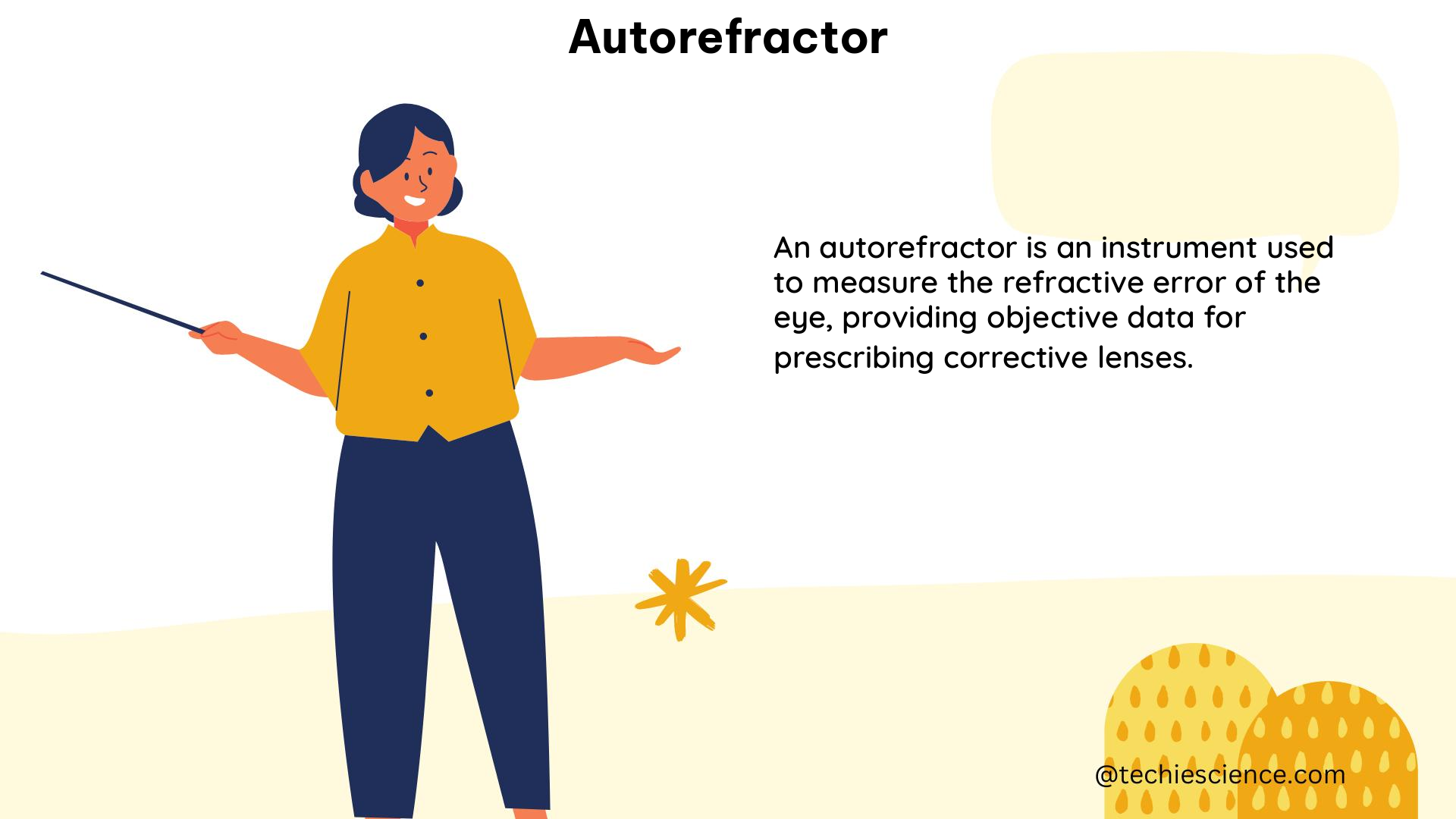
Autorefractors are sophisticated devices used to precisely measure the refractive error of the eye, enabling eye care professionals to determine the optimal lens prescription for glasses or contact lenses. These instruments employ advanced optical and electronic technologies to provide a comprehensive analysis of the eye’s refractive properties, delivering a wealth of data that can be used to diagnose and treat a wide range of vision-related conditions.

Understanding the Autorefractor Printing Data

The printing data generated by an autorefractor typically includes the following key measurements:

Sphere (SPH) Measurement

The sphere measurement indicates the degree of nearsightedness (myopia) or farsightedness (hyperopia) in the eye. Negative values represent nearsightedness, while positive values indicate farsightedness. This measurement is crucial in determining the appropriate corrective lens power.

Cylinder (CYL) Measurement

The cylinder measurement quantifies the amount of astigmatism present in the eye. A cylinder value of zero indicates no astigmatism, while positive or negative values represent the degree of astigmatism. This information is essential for prescribing the correct cylindrical lens component.

Axis Measurement

The axis measurement specifies the orientation of the astigmatism, ranging from 0 to 180 degrees. This data, combined with the cylinder measurement, allows for the precise alignment of the corrective lens to address the eye’s unique astigmatic properties.

Corneal Curvature (K-Readings)

The autorefractor measures the curvature of the cornea, the clear outermost layer of the eye, which is a crucial factor in determining the proper fit of contact lenses and diagnosing conditions such as keratoconus. The printing data typically includes the following corneal curvature measurements:

  1. MM1 (K1 or Flat K): Measures the curvature of the cornea in the flattest meridian.
  2. MM2 (K2 or Steep K): Measures the curvature of the cornea in the steepest meridian.
  3. MM: The average of the flat and steep M-readings, used to determine the overall corneal curvature.
  4. A: Indicates the orientation of the corneal curvature, measured in degrees from 0 to 180.
  5. R1: The data of the cornea in the flattest meridian.
  6. R2: The data of the cornea in the steepest meridian.

Corneal Dioptric Power

This measurement is used to calculate the prescription for contact lenses or assess the refractive power of the cornea.

Corneal Astigmatism

Corneal astigmatism is the difference between the flat and steep K-readings, representing the amount of astigmatism present in the cornea.

Pupil Distance (PD) Measurement

The pupil distance measurement indicates the distance between the pupils of the eyes, measured in millimeters. This information is crucial for properly fitting eyeglasses.

Autorefractor Accuracy and Validity
autorefractor

Numerous studies have been conducted to evaluate the accuracy and validity of autorefractors in comparison to other methods of refractive error measurement.

In a study comparing three autorefractors (Topcon RM-A 6000, Nidek AR 800, and Nikon NR 5000) with a hand-held Retinomax (R) autorefractor in 276 subjects and 48 infants under cycloplegia, the hand-held autorefractor showed better accuracy, with an AUC of 0.747 at a 0.25 cut point value under cycloplegia. Precycloplegic regression analysis revealed a very weak positive correlation (R^2 = 0.064) with high statistical significance (P < 0.0001), while cycloplegic regression analysis improved (R^2 = 0.303), indicating a positive relationship between the autorefractor (AR) and dynamic refraction (DR) methods.

Another study on accommodation by autorefraction and dynamic refraction in children found that the autorefractor measured -0.17 D of accommodative effort per unit change in dynamic refraction before cycloplegia and +0.90 D after cycloplegia. The infrared autorefractor showed significantly lower mean lag of accommodation when the near accommodative response was tested by the DR and AR methods.

In a study on the validity of autorefractor-based screening for irregular astigmatism, the autorefractor demonstrated a sensitivity of 78.1% (95% CI 73.1, 83.1) and a specificity of 76.1% (95% CI 71.0, 81.3) in diagnosing irregular astigmatism compared to conventional topography. Interestingly, the study found that age group was statistically significantly positively associated with specificity (P<0.001) and negatively associated with sensitivity (P=0.006). Additionally, female gender (P=0.008) and left eyes (P=0.05) had statistically significantly higher specificities compared to males and right eyes.

Practical Applications of Autorefractor Data

The comprehensive data provided by an autorefractor can be invaluable in various applications, including:

  1. Eyeglass and Contact Lens Prescriptions: The sphere, cylinder, and axis measurements are essential for determining the appropriate corrective lens prescription for glasses or contact lenses.
  2. Corneal Health Assessment: The corneal curvature (K-readings) and corneal dioptric power measurements can help eye care professionals diagnose and monitor conditions such as keratoconus, which affects the shape and refractive properties of the cornea.
  3. Astigmatism Management: The cylinder and axis measurements are crucial for accurately prescribing and fitting corrective lenses to address astigmatism, ensuring optimal visual acuity.
  4. Screening for Irregular Astigmatism: Autorefractor-based screening can be a valuable tool for detecting irregular astigmatism, which may indicate underlying eye conditions or the need for further examination.
  5. Pediatric Vision Assessments: Autorefractors can be particularly useful in evaluating refractive errors and accommodative function in children, providing valuable insights for vision care and development.

Conclusion

The autorefractor is a sophisticated and indispensable tool in the field of vision care, providing a wealth of detailed and quantifiable data that can be used to diagnose, treat, and monitor a wide range of eye-related conditions. By understanding the various measurements and their practical applications, eye care professionals can make informed decisions, deliver personalized treatment plans, and ultimately improve the visual health and quality of life for their patients.
References

  1. Comparison of Autorefraction and Retinoscopy in Infants and Young Children
  2. Accommodation by Autorefraction and Dynamic Refraction in Children
  3. Validity of Autorefractor-Based Screening Method for Irregular Astigmatism
  4. How to Read the Printing Data of the Autorefractor

A Comprehensive Guide to Telescope Parts and Usage

steps to use a telescope parts of a telescope

Telescopes are powerful tools that allow us to explore the wonders of the universe, from distant galaxies to the intricate details of our solar system. To fully harness the capabilities of a telescope, it’s essential to understand its various components and how to use them effectively. In this comprehensive guide, we’ll delve into the key parts of a telescope and provide a step-by-step approach to using them for optimal observation.

Telescope Types: Unraveling the Differences

Telescopes come in three primary types, each with its own unique characteristics and advantages:

Refractor Telescopes

Refractor telescopes use lenses to gather and focus light. The key parameters to consider are:

Aperture: The diameter of the objective lens, typically measured in inches or millimeters. A larger aperture gathers more light, enabling the observation of fainter celestial objects.

Focal Length: The distance between the lens and the point where the light converges, usually measured in millimeters. This determines the telescope’s magnification power.

Reflector Telescopes

Reflector telescopes use mirrors to gather and focus light. The critical factors are:

Aperture: The diameter of the primary mirror, which determines the light-gathering capability.

Focal Length: The distance between the primary mirror and the point where the light converges.

Catadioptric Telescopes

Catadioptric telescopes combine lenses and mirrors to provide a compact, high-quality image. The relevant parameters are:

Aperture: The diameter of the primary mirror or lens.

Focal Length: The distance between the primary mirror or lens and the point where the light converges.

Understanding these telescope types and their key specifications will help you choose the right instrument for your observational needs.

Eyepieces: The Window to the Cosmos

steps to use a telescope parts of a telescope

Eyepieces are essential components that allow you to view the celestial objects captured by the telescope. The focal length of the eyepiece, combined with the telescope’s focal length, determines the magnification power.

Magnification = Telescope Focal Length / Eyepiece Focal Length

For example, a telescope with a 1000mm focal length and a 25mm eyepiece would have a magnification of 40x (1000mm / 25mm = 40).

Choosing the right eyepiece for your observational needs is crucial. A higher magnification may not always be better, as it can reduce the field of view and introduce image distortion. It’s generally recommended to start with a lower magnification eyepiece and gradually increase the power as needed.

Finderscope: Your Celestial Navigation Tool

The finderscope is a low-power telescope attached to the main telescope. It serves as a guide, helping you locate and center celestial objects in the main telescope’s field of view.

To align the finderscope, follow these steps:

  1. Identify a bright star, planet, or the Moon as your target.
  2. Use a 26mm eyepiece (or a similar focal length for a reflector telescope) in the main telescope.
  3. Adjust the finderscope’s adjustment screws until the target object is centered in the finderscope’s view.

This alignment process ensures that the finderscope and the main telescope are pointing at the same celestial object, making it easier to find and track your desired targets.

Telescope Mounts: Stability and Precision

Telescope mounts play a crucial role in providing stability and precision for your observations. There are two primary types of telescope mounts:

Alt-Azimuth Mounts

Alt-Azimuth mounts allow movement in two axes: altitude (up and down) and azimuth (left and right). These mounts are relatively simple to use and are well-suited for casual stargazing.

Altitude: The angle between the telescope and the horizon, typically measured in degrees.
Azimuth: The horizontal direction of the telescope, often measured in degrees from north.

Equatorial Mounts

Equatorial mounts are designed to compensate for Earth’s rotation, making it easier to track celestial objects as they appear to move across the sky. These mounts have two axes:

Right Ascension (RA): The celestial equivalent of longitude, measured in hours, minutes, and seconds.
Declination (Dec): The celestial equivalent of latitude, measured in degrees.

Equatorial mounts require more setup and adjustment, but they offer superior tracking capabilities, making them the preferred choice for astrophotography and serious observational work.

Telescope Accessories: Enhancing Your Observational Experience

In addition to the core telescope components, there are various accessories that can enhance your observational experience:

  1. Eyepiece Filters: These filters can improve contrast, reduce glare, and enhance the visibility of specific celestial features.
  2. Barlow Lenses: These accessories increase the effective focal length of the telescope, providing additional magnification without the need for a new eyepiece.
  3. Diagonal Mirrors: These mirrors redirect the light path, allowing for more comfortable viewing positions.
  4. Dew Shields and Heaters: These devices prevent dew formation on the telescope’s optics, ensuring clear and unobstructed views.
  5. Astrophotography Accessories: Items like cameras, adapters, and tracking mounts enable you to capture stunning images of the night sky.

Incorporating these accessories can significantly improve your observational capabilities and unlock new levels of exploration.

Telescope Maintenance and Care

To ensure the longevity and optimal performance of your telescope, it’s essential to properly maintain and care for it. Here are some key considerations:

  1. Cleaning Optics: Gently clean the objective lens or primary mirror using a soft, lint-free cloth and a specialized optical cleaning solution.
  2. Collimation: Reflector telescopes require periodic collimation, the process of aligning the mirrors for optimal image quality.
  3. Storage and Transportation: Store your telescope in a dry, temperature-controlled environment and use a protective case or cover when transporting it.
  4. Periodic Inspection: Regularly check for any loose or damaged components and address any issues promptly.

By following these maintenance guidelines, you can ensure your telescope remains in top condition, providing you with years of reliable and enjoyable observations.

Conclusion

Mastering the art of using a telescope requires a deep understanding of its various components and how they work together. By familiarizing yourself with the different telescope types, eyepieces, finderscopes, mounts, and accessories, you’ll be well on your way to unlocking the wonders of the cosmos. Remember to always prioritize safety, maintain your equipment, and continuously explore the ever-expanding frontiers of amateur astronomy.

References:

Active Low Pass Filter:13 Facts Most Beginner’s Don’t Know!

EQ 13 3 1024x149 1
  • Definition of an active LPF
  • What does an active LPF do?
  • Components of an active LPF
  • Frequency Response
  • Design active LPF
  • Frequency scaling
  • Transfer Function
  • What is a second-order LPF
  • The transfer function of second-order active LPF
  • Design a second-order active LPF
  • Comparison between active low-pass and passive low-pass filter
  • Why do we use active LPF
  • Advantages of an active LPF
  • FAQs

What is an Active Low Pass Filter?

First things first, let’s discuss what a simple Low Pass Filter is-

Low Pass Filter is a type of filter which mainly passes signals with a frequency lower than the particular cut-off frequency and attenuates all the frequency higher than the cut-off range ”.

Now, an Active Low Pass Filter is made of active components like Op-amp, resistors, and it also carries lower frequency signals with less resistance and has a constant output gain from zero to a cut-off frequency.

Components of Low Pass Active Filter: 

Active filters consist of active components as the name implies such as Operational amplifier, transistors or FET within the circuitry.

An active filter typically consists of amplifiers, capacitors and resistances.

So generally, Low Pass Active Filter is any filter using an Op-amp to improve the performance and predictability in such a low cost.

How does an Active Low Pass Filter work

Active Low Pass Filter


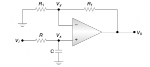
In the above figure, it’s a commonly used low pass active filter.

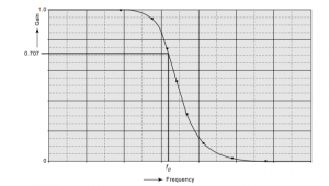
Frequency Response of Low Pass Filter:

LPF CHARAC 1.1 1
Characteristic Curve of an active LPF

Active Low Pass Filter Design:

Resistance R =

EQ 10 2

              Fc = cut-off frequency

              Ωc = cut-off frequency

              C = capacitance

EQ 11 2

A cut-off frequency can be varied by multiplying it with RC or C.

EQ 12 2

Transfer Function of a First Order Active Low Pass Filter:

Differential Equation for the filter –

EQ 13 3

Second-Order Active LPF:

What is a second-order LPFs?

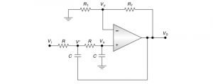
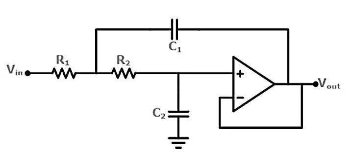
To build a second-order filter, we usually use an op-amp, and therefore the second-order filter can also be called as a VCVS filter; where VCVS is referred to ‘Voltage Control Voltage Source’ amplifier. We design a second-order filter along with a first-order active RC filter.

As it is a low pass filter, it only allows the lower frequency signals to pass, and it attenuates all the higher frequencies above the specified frequency range.

A second-order low pass filter attenuates the higher frequency signals more precisely. The gain reduces at the rate of 12 dB per octave. In other way it is 40 dB/decade.

2ND ORDER LPF
Second order LPF diagram


In a second order filter,

EQ 1 2

When the resistor and capacitor values are different,

EQ 2 4

When the resistor and capacitor values are same,

EQ 3 4

Transfer Function of a Second Order Active Low Pass filter:

The Transfer Function is denoted as,

EQ 4 4

The magnitude of the Transfer function –

EQ 5 3

Where ωc is the cut-off frequency.

Frequency-responses of second-order low-pass active filters is given.

2nd ORDER CHARAC
The frequency response of 2nd order LPF


Design of a second-order active low pass filter

First, we choose a value of the cut-off frequency, ωc (or fc).

Find R,

EQ 6 3
  • Rf comes as –

                              Rf = K(2R) = 3.172 R.

  • Find R1 while K = 1.586
LAST EQ

Differences between Active Low Pass Filter & Passive Low Pass Filter:

  • Active components are effectively costlier, that’s why the active filters are expensive as well, whereas the cost of passive filters is lower due to the presence of the passive components.
  • Active Low Pass filter circuit is a complex one, while a passive low pass filter circuit has less complexity.
  • To operate an active LPF, we need an external power supply for operating it. But passive filters do not require external power because it drives the energy for its operation from the applied input signal.
  • Passive filters contain more components than an active low pass filter; that’s why they are heavier in weight.
  • Active LPF is more sensitive during temperature change, but the passive ones show less sensitivity with the growth of temperature.

Why to use Active LPF?

Due to the less complex circuitry and lower price than the other active filters, we use Active LPF in many fields.

Check out them here – Low Pass Filter Applications.

  • Low pass filter is used in ‘hiss’ filters.
  • These filters are also used in ADCs. They act as anti-aliasing filter in that circuits.
  • LPFs are also used to prevent the harmonic  emissions from the RF transmitters.
  • These filters find applications in the music systems also. There these filters omits the high-frequency components.

Advantages of an Active Low Pass filter:

  • For a transfer function with inductive characteristics, it can achieve satisfactory output with an acceptable range of frequencies.
  • The high input impedance and low output impedance of the op-amp make the circuit excellent while cascading.
  • Due to better amplification, it provides more gain.

What is 3db frequency in an active low pass filter?

3db is the power level, where the cut-off frequency is at 3dB below than the maximum value, and 3dB is usually half of the maximum power.

To read more about electronics click here

Active High Pass Filter:11 Facts You Should Know!

ACTIVE HPF DIAGRAM 300x136 1

In this article, we will discuss about few basic concept related to active high pass filter and try to answer few questions in following sections and we will try to learn about some important application of active high pass filters with advantage.

  • What is an active high pass filter?
  • Working Principle of an active HPF
  • Time Response & Frequency Response
  • Cut-off Frequency of an active HPF
  • What is a transfer function for an active HPF
  • Design a first order active order HPF
  • Second order active HPF
  • Transfer Function for second order HPF
  • Advantages of active High Pass Filter
  • Applications of a HPF
  • FAQS

Active high pass filter definition:

An active high pass filter is nothing but a circuit contains an active component such as a transistor, an operational amplifier(op-amp), etc. These components are mainly used for better performance or better amplification.

What are the components of an active high pass filter?

We can make an active high pass filter by adding an op-amp across a passive high pass filter.

To imply simplicity, time effectiveness and due to growing technologies an op-amp designing, generally, an op-amp is used for an Active High Pass Filter design.

In an active high pass filter, the limitation we have is the op-amp bandwidth. It means that the op-amp will pass the frequency according to its gain and the open-loop characteristics of the op-amp.

Circuit Diagram of active high pass filter:

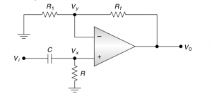
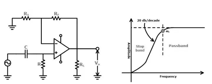
Active High Pass Filter

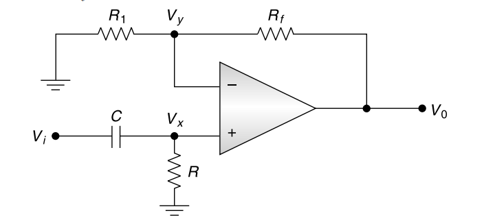
In the above figure, the CR network does the filtering, and the op-amp is connected as a unity-gain follower. The feedback resistor, Rf, is included to minimize the dc off-set.

Here,

EQ 1 1

The voltage across the resistor R,

EQ 2 1

Since op-amp gain is infinite, we can therefore derive.

EQ 3 1

Where

EQ 4 1

= Passband gain of the high pass filter,

f = Frequency of the input signal (Hz),

EQ 5

= cut-off frequency of the high pass filter (Hz)

    The Gain Magnitude,

EQ 6

And phase angle (in degree),

EQ 7

Working Principle of an active high pass filter:

First-order filters are the simplest form of any filters that contain only one reactive component, i.e., capacitor, as it is also used in passive filters. To transform it into an active filter, an op-amp is used to the output of a passive filter.

Now, the op-amp is used for different configurations. Each configuration has additional attributes to the performance of the filter.

The main thing to be remembered is a first-order filter’s roll-off rate. The roll-off rate is the rate of change in the gain of a filter in its desired stopband. It shows us the steepness in the curve and how fast the growth tends to increase with frequency.

First-order filters have a roll-off rate of 20dB/decade or 6dB/octave.

        Roll Off Rate = -20n dB/decade = -6n dB/octave

Time Response & Frequency Response of an active HPF

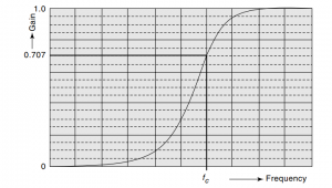
HPF CHARAC CURVE 2

To operate a high pass filter, the verification can be done from the gain-magnitude equation as follows:

At very low frequency, i.e., f<fc,

EQ 8

At f=fc,

EQ 9

At f>>fc,

EQ 10
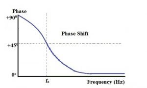
PHASE SHIFT DG

The bandwidth of the active high pass filter shows the value of frequency from which signals are allowed to pass. As an example, if the bandwidth of that high pass filter is given as 50 kHz, that means the only frequencies from 50 kHz to infinity are allowed to pass the range of bandwidth.

The phase angle of the output signal is +450 at the cut-off frequency. The formula to calculate the phase shift of an active high pass filter is

                     Ø= arctan (1/2πfRC)

Active High Pass Filter Transfer Function

The impedance of the capacitor keeps frequently changing, so electronic filters have a frequency-dependent response.

The complex impedance of a capacitor is given as,

EQ 11

Where, s= σ +jω, ω is the angular frequency in radians per second.

The Transfer Function of a circuit can be found using standard circuit analysis techniques such as Ohm’s Law, Kirchoff’s Law, Superposition Theorem, etc.

The form of a T.F is derived from the ratio of Output Voltage to Input Voltage

EQ 12

The standard form of the transfer function is :

EQ 13

Where,

a1 = Amplitude of signal

ω0 = Angular cut-off frequency

Cut-off Frequency:

What do we mean by cut-off frequency ?

By cut-off frequency, we define the useful or essential part of a spectrum. It is simply a frequency level above or below a device or filter cannot response or can be operated properly.

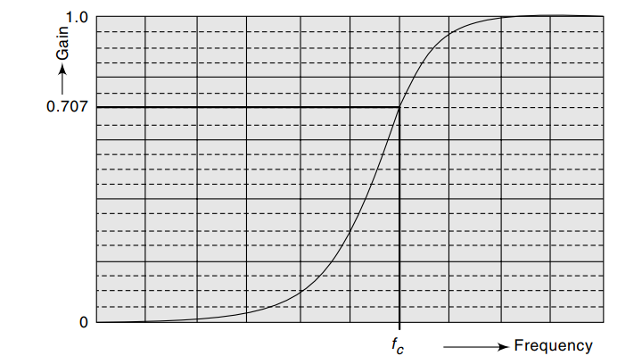
The Cut-off frequency for an active high pass filter is the particular frequency at which the load(output) voltage equals 70.7% of the source(input) voltage. The origin or output voltage is more significant than 70.7% of the input or load voltage and vice versa.

The cut-off frequency also indicates the frequencies at which the power of the output path falls to half its maximum value. These half-power points correspond to a fall in the gain of 3dB(0.7071) relative to the maximum dB value.

Filter Designing of Active High Pass Filter:

To construct an active high pass filter, we need to implement the following steps-

A value of the cut-off frequency,

EQ 14

is chosen.

A value of the capacitance C, usually between 0.001 and 0.1µF, is selected.

The value of the resistance R is calculated using the relation,

EQ 15

Now, the values of R1 and Rf are selected depending on the desired pass-band gain, using the relation,

EQ 16

Second-Order Active High Pass Filter:

What is a second-order filter?

The maximum delay in each sample used in generating each output sample is called the order of that particular filter.

Second-order filters mostly consist of two RC filter, which is connected together to provide a –40dB/decade roll-off rate.

SECOND ORDER HPF DIAGRAM
Second-Order Active High Pass Filter

Where DC gain of the amplifier =

EQ 17

The Transfer Function of a second-order active high pass filter can be obtained from the transfer function of the low pass filter by the transformation,

EQ 18 1
  • Substituting s=jω, the transfer function is,
EQ 19

In the above equation, when ωà0, |H(jω)|=0. Thus the low-frequency gain of the filter is zero.

If we compare it with Butterworth filter transfer function, we get

EQ 20
LAST DIAGRAM
Characteristic curve of a second order HPF

The Frequency response of a second-order active high pass filter is shown in the above diagram. It is noted that the filter has a very sharp roll-off response.

The design procedure for a high pass will be as same as low pass.

The frequency response will be a maximally flat one, i.e., having a very sharp roll-off response.

Advantages of using Active High Pass Filter:

There are so many vital benefits of an active High Pass Filter, some of them are:

  • Whenever there is a small signal is present, an active High pass Filter is used to increase the amplification factor, which also increases the amplitude of those small signals.
  • Due to very high input impedance, active high pass filters can transfer efficient signals without any loss in any preceding circuit.
  • Active filters usually have very low output impedance, which is perfect for transferring efficient signals to its next stage, mostly when they are used in different multistage filters.
  • This type of filters gives us smooth frequencies.
  • They have a sharp roll-off response.
  • Strong broadcasting power to receivers to select desired channel frequency.
  • Best for audio processing in any electrical or electronic device.
  • Active HPF prevents amplification from DC etc.

Application of Active High Pass Filter:

  • To transmit higher frequency in case of video related filters.
  • We use HPF as a treble equalizer.
  • We often use HPF as a treble boost filter.
  • We are changing the frequency depending on different waveforms.
  • Active High Pass filters are also used in oscilloscopes.
  • In the generator, these filters are used.


Frequently Asked Questions

Where are high pass filters used?

      The high pass filters are used in all audio sources to remove unwanted noise that lurks below the important frequencies.

Many unwanted sounds can be hidden by some louder core of a high pitch signal and can be overlooked. We don’t get to hear the rumble due to the limits of hearing as the lowest parts of the spectrums are around 20-40 Hz. High pass filters also eliminate those noises or reduce it that makes them nearly silent.

Can I get the output of a high pass filter as a power source?

A high pass filter is an electronic filter that passes signals with higher frequencies which are above the cut-off frequency range and also attenuates the frequencies which are below the cut-off range.

Now, the output of the specific high pass filter has no DC(0Hz) voltage due to its specified cut-off frequency(fc). The lower cut-off frequency of an active high pass filter is 70.7% or -3dB(dB= -20log Vout/Vin) of the voltage gain which it allows to pass can be used as a power supply as well.

What does corner frequency mean in regards to high pass filter?

The corner frequency, which is also called as cut-off frequency, defines a specific frequency at which the transfer attenuation reaches -3dB below(50%) the magnitude from the 0dB or pass-band level.

To read more about electronics click here

Low Pass Filter:13 Facts You Should Know

Equation 1 1024x85 1
  • Definition of Low Pass Filter
  • Circuit Diagram
  • Active and Passive Low Pass filter
  • What does a LPF do? How does it work?
  • Operation
  • Frequency Response
  • Transfer Function of a LPF
  • Designing a LPF
  • Corner frequency of a low pass filter
  • Ideal & Real Filter
  • Low Pass Filter vs High Pass Filter
  • Advantages of a LPF
  • What are the uses of a low pass filter
  • FAQs

Definition of LPF:

 “Low pass filter carries lower frequency signals with less resistance and has a constant output gain from zero to a cut-off frequency.”

Generally, a low pass filter does attenuation of frequencies above cut-off points.

Circuit Diagram of a Low Pass Filter:

There are two types of active filter exist, they are-

Active Low Pass Filter
figure 1.1 Active Low Pass Filter
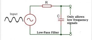
  • Passive Low Pass Filter – consists of mostly passive components like capacitors, resistors, etc.
LPF PASSIVE DG
figure 1.2 Passive Low Pass Filter

How does a Low Pass Filter Work?

What does a low pass filter do?

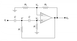
In figure 1.1, it’s a commonly used low-pass active filter.

The filtering is commonly done by the RC network, and the op-amp is used as a unity gain amplifier. The resistor RF(= R) is included for Dc offset.

At DC, the capacitive reactance is infinite, and the dc resistive path to ground for both terminals should be equal.

Here, all the voltages Vi, Vx, Vy, V0 are measured concerning ground.

The input impedance of the op-amp is always infinite; no current will flow into the input terminals.
Equation 1

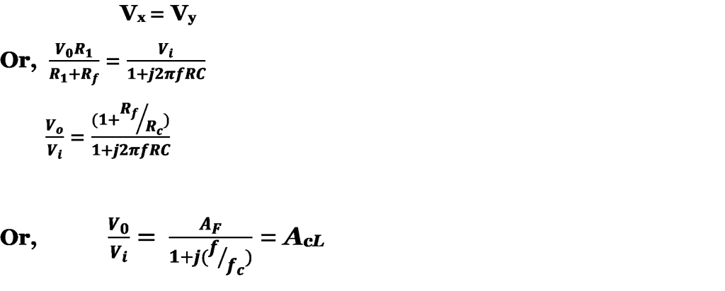
According to the voltage divider-rule, the voltage across the capacitor,

EQ 2 2

Since the op-amp gain is infinite,

EQ 3 2

Where,

EQ 4 2

= pass-band gain of the filter

                 f = frequency of the input signal

EQ 5 1

= cut-off frequency of the signal

AcL

 = closed-loop gain of the filter as a function of the frequency.

The Gain Magnitude,

EQ 6 1

And Phase Angle (in degree),

EQ 7 1

Operation of a Low Pass Filter:

The operation of the low-pass filter can be verified from the gain magnitude equation as follows-

At very low frequencies, i.e., f>>fc,

EQ 8 1

At f=fc,

EQ 9 1
At f>fc,

              |AcL|<AF

Thus the filter has a constant gain of AF from 0 Hz to the cut-off frequency fc. At fc, the growth is 0.707AF, and after fc, it decreases at a steady rate with an increase in frequency.

Here, the actual response deviates from the linear dashed-line approximation at the vicinity of ‘fc.’

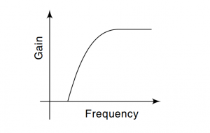
Frequency Response of Low Pass Filter:

LPF CHARAC 1.1
Low pass filter characteristics

How to make a Low Pass Filter?

Low pass filter design:

A value of the cut-off frequency ωc is chosen.

Capacitance C is selected with a certain value; usually, the value is between 0.001 and 0.1µF. Mylar or tantalum capacitors are recommended for better performance.

The value of R is calculated from the relation,

EQ 10 1

              Fc = cut-off frequency in hertz

              Ωc = cut-off frequency is in radian second.

              C = in Farad

Finally, the values of R1 and RF are selected depending on the desired pass-band gain by using the relation,

EQ 11 1

Frequency Scaling:- Once a filter is designed, there may be a need to change its cut-off frequency. The method of converting an original cut-off frequency fc to a new cut-off frequency is called ‘frequency scaling.’

To change a cut-off frequency, multiply R or C, but not both by the ratio:-

EQ 12 1

Corner frequency & Cut-Off Frequency of a Low Pass Filter:

The transition of a low pass filter is always swift and smooth from the pass-band to stopband. Also, a cut-off frequency is not any parameter to measure the goodness or badness in a range of frequency. The cut-off frequency is more accurately referred to as the -3dB frequency, i.e., it is the frequency at which the magnitude response is 3dB lower than the value at 0 Hz.

What is Pass-band?

“Pass-band is the particular range of frequencies which a filter pass through inside it.”

For low pass filters, the frequencies that move towards the end of the pass-band cannot have any significant gain or attention.

What is Stopband?

“A filter always carries filters within a given band, and rejects the frequencies which are below the given range. This particular range is known as a Stopband”.

As the limitations are there for low pass filters, the stopband attenuates at a particular frequency, which moves near the cut-off frequency closer to 0 Hz.

The transfer function of a Low pass Filter:

What is a Transfer Function?

Transfer function is a complex number that has both magnitude and phase. In the case of filters, transfer function helps to introduce a phase difference between input and output.”

Since low pass filter allows low-frequency AC signals to pass through it, the output gets attenuated. We use different active and passive components to make a filter, which eventually has other characteristics. The transfer function tells us how one input is related to an output depending on the component’s characteristics. The transfer function can easily be determined from a graph of the output signal at various frequencies. We can also calculate the transfer function using Kirchoff’s Laws to derive the filter’s differential equation.

EQ 13 1

As more signal passes through it, the filter will apply a phase shift to the output signal for the input signal. Hence, the transfer function of a filter is a complex function of frequency. It also contains all the vital information we need to determine the magnitude of the output signal and its phase.

Ideal Filter & Real Filter:

Sometimes, for the reason of simplification, we often use the active filters to approximate ways. We upgrade them into an ideal and theoretical model, which is called ‘Ideal Filter.’

The use of these standards is insufficient, leading to errors; then, the filter should be treated based on accurate real behavior, i.e., as a ‘Real filter.’

The main key terms of an ideal filter are

  • A gain unit
  • Complete degradation of the input signal across the bands.
  • The transition of response from one zone to another is quite abrupt.
  • It does not create any distortion when the signal passes through the transit zone.

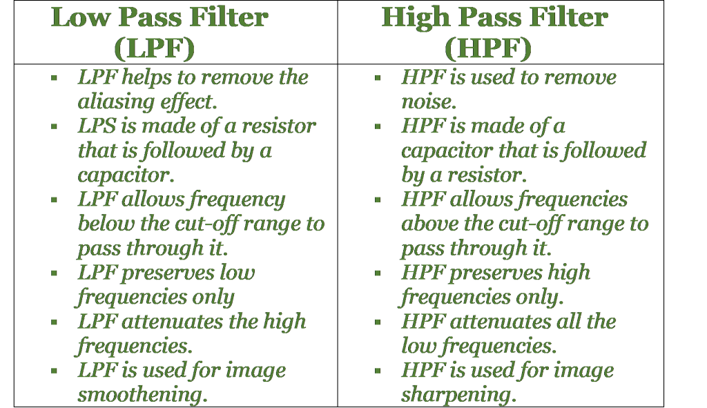
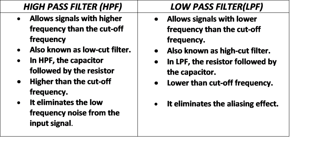
What are the differences between the Low pass filter & High pass filter?

lpf vs hpf

What are the advantages of a Low Pass Filter?

  • Low-Pass filters can easily remove aliasing effects from a circuit, which makes the circuit working smoothly.
  • Low-Pass Filters are cost-effective so that it can be used easily.
  • Low-Pass Filters have low output impedance; thus, it prevents the filters cut-off frequency from being affected because of the load.

Applications of a Low Pass Filter:

  • A low-pass filter is used in ‘hiss’ filters.
  • LPF is used in audio speakers to reduce high frequency.
  • LPF can be used as an audio amplifier and an equalizer.
  • In Analog to Digital converter, LPF is used as anti-aliasing filters to control signals.
  • LPF is used in image smoothening, image blurring.
  • LPF is also used in radio transmitters to block harmonic emissions.
  • These filters are used in music systems to filter the high-frequency sounds, causing echo at higher sounds.

What is a passive low pass filter?

A passive low pass filter is a filter made of all passive components like capacitors, resistors, etc. It causes a lesser output level compared to the input level.

What is an RC low pass circuit?

An RC low pass circuit is made of only Resistors and Capacitors, as the name implies. It is an essential passive filter, as well. In this filter, the reactance of a capacitor varies inversely with frequency, and the value of the resistor remains constant as the frequency changes.

What is a Butterworth Low pass Filter?

A Butterworth filter is that type of filter where the frequency response is flat over the pass-band region. A Low-Pass Butterworth filter provides a constant output from DC source to a particular cut-off frequency and rejects the higher level frequencies.

How can a second order low pass filter be constructed?

We know that a first-order low-pass filter can be made by connecting a single resistor and capacitor whose single pole can give us a roll-off slope -20dB/decade. To make a second-order passive low pass filter, we connect or cascade two passive filters (first-order). It is also a two-pole network.

Write down the corner frequency of a second-order filter.

In a second-order low pass filter, we observe a -3dB corner frequency point and therefore, the pass-band frequency changes from its original value as calculated in the equation:

last equation 1

To read more about electronics click here

Comprehensive Guide On Filters (Read This First!)

active filter 001 300x221 1

Content

  • In this article, we will discuss about few basic concept related to filter and few Frequently asked questions
  • What is a filter ? filter definition
  • How does a filter work?
  • What are the types available ?
  • What are the Active Filters? Explain with definition
  • What are the Passive Filters? Explain with definition
  • What are the points of conflict between active and passive types.
  • What is the filter symbol?
  • Examples
  • What are the Applications of filter in optics and electronics industry ?
  • What is the Response curves for most common types?
  • What is Time response of a filter ?
  • What is Frequency response of a filter?
  • What is Order of a filter?
  • How first-order output differs with A second-order filter ?
  • What is Corner frequency, Cut off frequency, break frequency
  • What is Bandwidth (BW) ?
  • What is Resonant Frequency?
  • What is Resonant Filters
  • What is ideal and real filters ?

What is a Filter?

A filter is a frequency selective network consisting of four terminals with reactive elements to transmit a specified range frequency.

  • The band of frequency transmitted through it is called Pass-band.
  • The band of frequency, which gets attenuated by it, is called attenuated on Stop-band.

Filters are of two types- analogue digital. Now, based on the components used, They are of two types – Active types and Passive Types.

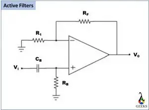
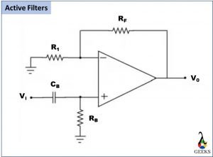
The below image represents a diagram of active types(one of the very popular and important types).

Filter Circuit : active filter
Filter Circuit : active type

Know about Active High Pass Types. Click Here!

Characteristics of an active filter

As the titles suggest, these types are made using active components. Some of the active transistors are – transistors (BJT, FETs), any other electronics devices which are capable of amplifying a signal or can produce powers.
If there is a need to increase the characteristics, various stages are joined in a certain or specific ways.

How to design an active low pass filter?

To design an active types, we may use IC741, an Op-amp, configured with 8 pins. The op-amp is to be supplied with DC power along with resistors and capacitors of different values.

Passive Filters

Passive types are designed using passive devices.

PASSIVE FILTER

Know about Applications of Active High Pass Types. Click Here!

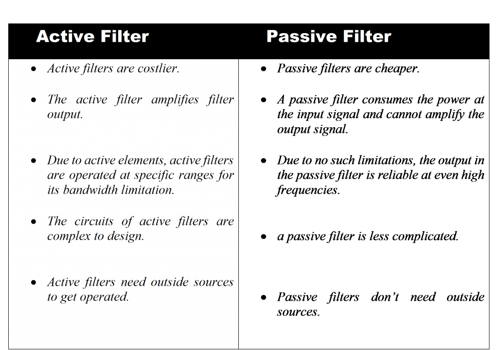
Comparison of Active and passive types

An active type may have an advantage, increasing the signal power available in comparison with the input. Whereas a passive one dissipates energy from the signal. For various ranges of frequencies, such as at sound frequencies and under, an active type may realize a specified transfer function with no use inductors, that are comparatively big and costly components in contrast to resistors and capacitors, and that are more costly to create with the essential high quality and precise values.

Numerous stages may be cascaded when wanted to enhance attributes. By comparison, the layout of multiple-stage passive blockers needs to take into consideration every phase’s frequency-dependent loading of the previous stage. Since inductors aren’t utilized, they can be reached in really compact dimensions.

  • Passive type suffers from attenuation of signals. There are various ways; one popular method of control or restoration is by using amplification through the Active type applications. The major point of conflict between the active and passive types is the ‘amplification’.
  • Compared to a passive one, active type are composed of active components in operational amplifiers, transistors, or FET’s within their circuit design, as described in earlier sections. These components draw power from the external power source, use it for amplification of output. That’s an added advantage compared to a passive one.

Know about Active Low Pass Types. Click Here!

Why is an active filter needed at low frequencies?

  • An active type is needed at lower frequencies because it helps achieve low output impedance while providing high input impedance. It also stabilizes different frequency ranges as multiple stages can be cascaded with it.

Difference between Active & Passive types

ACTIVE VS PASSIVE 1

Know about Applications of Active Low Pass Types. Click Here!

These can be categorized and sub-categorized from several points of view. The most common divisions and sub-divisions are- active or passive type; high-pass type low-pass type, bandpass type, band-reject/notch type or all-pass type; digital or analog type discrete-time or continuous-time type; linear or non-linear type; infinite impulse response (IIR) or finite impulse response (FIR) and so on.

Examples:

Active types and Passive types are designed to modify certain band of frequency in a desired way. They have different types according to their needs. The categories are given below.

  • Low pass types (LPF)
  • High pass types (HPF)
  • A bandpass types (BPF)
  • Band reject/stop types (BSF)

Applications:

They are nowadays used in many purposes of the electronic circuit, and its applications are immense. Moreover, it’s possible to improve the circuit gain by using different filters in different ways, either active or passive types, especially in active types. Active types use amplifiers, and we know that it helps increase gain. This article will discuss two type, such as Low pass type, High pass type with appropriate diagrams and simulated wave shapes for both active and passive condition in the following sections with the importance of using higher-order in the HPF and LPF.

In electronics, some applications are as follows:

  • In Radio communication System for Radio tuning to a specific frequency: They are used to enable radio receivers to only “see” or “detect” the desired signal and reject all the other signals by assuming their different signal frequency. So noise-free signals can be received. The high-frequency bandpass types are used for channel selection in central telephone offices.
  • Power Supply Design: They are used to remove noise or high frequencies usually present on AC input lines. These are also applied to decrease the ripple.
  • Analog-to-digital conversion (ADC): They are utilized in most of the ADC input to minimize aliasing.
  • Modify digital images: It can be used to modify digital images also.
  • Data analysis: They are also very helpful to remove specific frequencies in data analysis.

Frequency Response & Time Response:

Time-domain refers to the change of signal’s amplitude with respect to time. In contrast, in the frequency domain, Frequency refers to the occurrence of an event in a given period.

1920px Bandform template.svg
A Frequency Response of different type
Image credit: SpinningSpark real life identity: SHA-1 commitment ba62ca25da3fee2f8f36c101994f571c151abee7, Bandform templateCC BY-SA 3.0

What is Bandwidth (BW)?

For filters, bandwidth is the difference between the upper and low -3dB points.
For example, if a bandpass filter has -3dB cut-off points and set to 200Hz and 600Hz, then the filter bandwidth will be = (BW) = 600-200 = 400Hz.

What do you mean by the Q Factor?

Q factor is given by the ratio of resonant frequency to the BW.

Q = 2 * π * (Maximum Amount of Energy Stored) / (Energy Dissipated per Cycle)

Q FACTOR EQ 1
Q FACTOR EQ 2

A greater Q value represents the filter is more selective as Q factor is a parameter which judges the selectivity.

Resonant Frequency

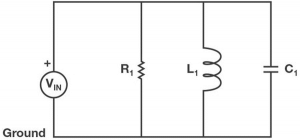
Resonant frequency is simply given by the frequency of the given resonant circuitry. A Resonant circuit is also popularly known as the tank circuit or the LC circuit. A resonant circuit is designed using parallelly placed inductors and capacitors and resistors.

RESONANT FREQ CKT
A parallel Resonant Circuit

 Oscillation of a system is given by the following equation –

RESONANT FREQ EQAUATION

Where,

f= frequency in Hertz

L= Inductance in Henry

C= Capacitance in Farads

Orders of Filters

Higher-order filters provided more excellent roll-off rates between passband and stopband. Higher-order filters are also required to achieve required levels of attenuation or sharpness of cut-offs.

Active type and Passive type also have variation in different types of orders, such as:

  • First Order Low pass active types, First Order High pass active types, First-order Bandpass active types, First-order Band stops active types.
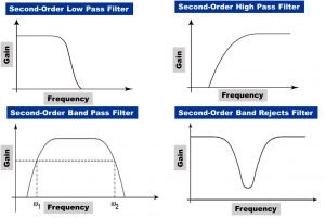
  • Second order Low pass active types, Second order High pass active types, Second-order Bandpass active types, Second-order Band stops active types.

The frequency response of second-order are shown below –

2nd order filter 3
Frequency response of Second-order

Ideal type & Real type:

Sometimes, for the reason of simplification, we often use the active filters to approximate ways. Later they are modified and termed as ‘ideal filter’. Filters, which operate in reality considering all the possible factors, are real ones.

To read more about electronics click here

9 Facts On High Pass Filter:Function,Types,Applications

1st ORD HPF
  1. What are the high-Pass filters?
  2. How does a high-pass filter work?
  3. What does a high-pass filter do in a circuit?
  4. What is a high-pass filter symbol?
  5. What are the type of high-pass filter ?
  6. Different examples of high-pass filters
  7. Time response and Frequency response of hpf
  8. Cut-off frequency of hpf
  9. Transfer function of high-pass filter
  10. Comparison between high-pass and low-pass filter


What is a High Pass Filter?

High pass filter is a circuit that attenuates all signals of frequencies which belong to the below cut-off frequency and gives a constant output or gain above this particular frequency.”

First-order High pass filter
First-order type

In the above figure, the CR circuit does the ‘filtering’ work. The op amp is linked with a voltage follower. Now, the feedback system is also incorporated to cancel out the offset voltage according to the property of the operational amplifier.

Here,

EQ 1

The equation can be calculated using the property of ideal operational amplifier which states that an operational amplifier has infinite gain. Here, f represents input signal’s frequency.

EQ 2

Where= HPF’s passband gain,

f=Input signal’s frequency (It is also the cut-off freq.),

EQ 3
PHASE ANGLE

Operation of a High pass filter:

Here, the gain-magnitude equation does the job of verification at a lower level of frequency.

EQ 8 shallow freq

At f = fc,

EQ 9 fc
EQ 10 f fc

High Pass Filter Characteristics

High Pass Filter Characteristics

Types of High Pass Filter:

  • Passive High Pass Filters
  • Active High Pass Filters

An active high pass filter is nothing but a circuit contains an active component such as a transistor, an operational amplifier(op-amp), etc. Using these devices gives us more efficiency.

Advantage of High Pass Filter :

Active high pass filters have several advantages over other types of filters. The major advantages are given below.

  • 1. Amplification of weaker signal,
  • 2. Efficient transmission of signal (with minimal loss),
  • 3. Efficient performance when used in a multistage filter.

Working of high pass filter.

The most straightforward and simple type of filter is the First order Filter. It has a single reactive component. The transforming process is quite simple. You have to add just an op-amp.

Operational amplifiers have several configurations. Different configurations have different attributes and impact in the filter’s performance.

Now, note of the roll off rate of a first order filter. Roll off rate is defined as the rate at which the gain of a filter changes in the operational stop band. The rate represents the steepness of the curve and it also help us to find out the increase rate of the growth.

The first order filters come up with a growth rate 20 dB/decade or in other terms, it can be said the growth rate is 6db/Octave.

High Pass Filter Transfer Function

We know that the capacitor’s impedance varies with the frequency. That is why electronic-filters comes up with response which are dependent on frequencies.

The impedance of a capacitor is typically given by the following equation.

EQ 11 z

Where, s= σ +jω, ω represents the angular frequency.

The transfer Function is derived using some basic theorems of network theory.

The Transfer Function is given by ratio of output to the supplied input. The typical representation of transfer function is given as follow.

EQ 12 ohm

The typical transfer function is :

EQ 13 TF

Where,

a1 represents Amplitudes of signals

ω0 represents Angular cut-off frequencies

Application of Active High Pass Filter:

  • To transmit higher frequency in case of video related filters.
  • The frequency is changed based upon various waveforms.
  • The active ones finds application in the CROs, generators.

Passive High Pass Filters:

Why are passive high pass filters used?

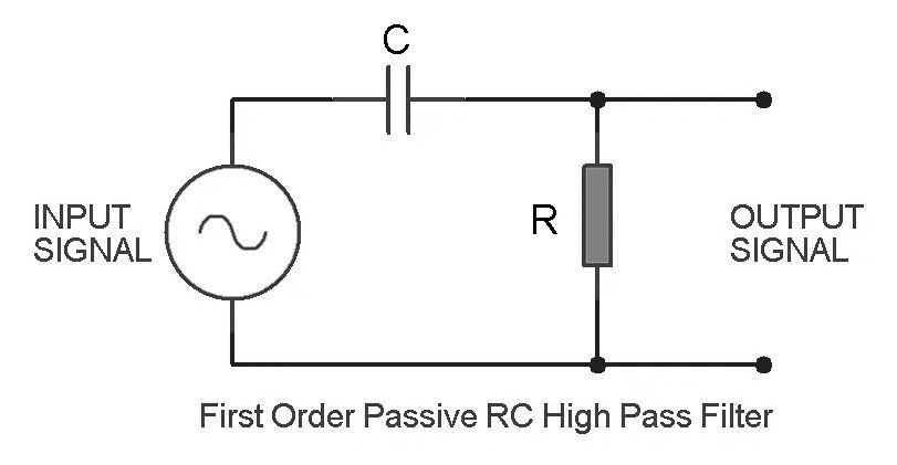
A filter is called passive when there won’t be any external power, and the input signal also remains unamplified due to the passive components present in the Filter. The passive components may be the same as low pass, but the overall connection is always reversed. The passive components are Resistor(R) and Capacitor(C), so it is an RC filter combination.

The name “passive,” “high,” “pass,” and “filter” suggest that the Filter will only pass the higher frequency, i.e., it will block the low frequencies.

Passive High Pass Filter (RC)

In the above circuit, the output voltage is determined across the resistor(R); when the frequency increases, the reactance of the capacitor decreases, so the output and gain increases simultaneously.

The formula to calculate the frequency of the RC circuit is,

f=1/2πRC

How to build an RC High Pass Filter:

To build an RC HPF, the components we need are as follows,

Frequency:

                                    (0.00000001F) = 15,293 Hz, the greater the output, the more signal gets attenuated.

If we give an AC signal input to the circuit from a function generator and sets the signal to a low frequency, the capacitor will block the voltage signal. So the low-frequency signals which get blocked do not reach past the capacitor. The high-frequency signals keep going and pass to the output.

Passive High Pass Filters are used in:

  • Audio amplifiers
  • In speaker systems
  • In different music control systems etc.

First Order High Pass Filter vs. Second Order High Pass Filter

  • The second-order high-pass filter comprises two different reactive components.
  • First-order HPF has a transfer function of the first order; on the other hand, second-order HPF has a transfer function of second order.
  • The first order filter differs from the second order filter on the basis of the stopband. The slope of the graph of a second order is typically the algebraic double of the first order.

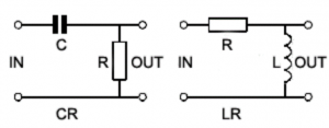
Passive RL High Pass Filter:

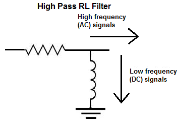
PASSIVE RL FILTER DG
Passive RL High Pass Filter

This circuit consists of a resistor and an inductor. The inductor in the circuit passes all the lower frequencies and reduce the voltages across it. It also keeps the output voltage closer to the input voltage.

There is a frequency response in dB below the circuit for a specific range of frequencies.
The lower cut-off frequency for an RL high-pass filter is determined by the inductor and the parallel combination of RF and RL, by the formula:

PASSIVE RL EQ

Where, REQ = RF||RL

How to build an RL High Pass Filter:

To build an RL HPF, we need,

  • A function Generator
  • A Resistor
  • An Inductor
  • Oscilloscope

For making the circuit, we may use a 470mH inductor and a 10KΩ resistor.
The circuit forms a high-pass filter and helps the high-frequency signals to pass through to the output. It also filters the low-frequency signals through the inductor.

Butterworth High Pass Filter:

What is a Butterworth Filter?

Butterworth filter is probably the first and best-known filter approximation.”

The Butterworth filter is created to get a smooth frequency response graph in the passband.

BUTTERWORTH EQ

Circuit Image –

Butterworth Filter
The circuit diagram of Butterworth high pass filter and frequency response 


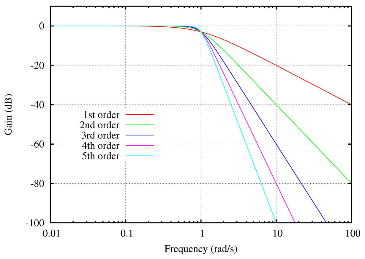
Butterworth orders
Frequency response of Butterworth filters with orders
Image credit: OmegatronButterworth ordersCC BY-SA 3.0

Chebyshev High pass Filter:

Chebyshev High pass Filter
Chebyshev filter

The Butterworth filter is created to get a smooth frequency response graph in the passband. Filters can be classified into two categories. The categories are ‘Chebyshev Filter’ and ‘Inverse Chebyshev Filter’.

The filter response comes out to be response of a Butterworth filter, if the ripple value is fixed at 0%. Typically the ripple value is fixed at 0.5% for applications in digital filters.

Chebyshev frequency response

Chebyshev response
Chebyshev response
Image Credit: Pfalstad / CC BY-SA
Electronic linear filters
frequency response of all the classic electronic filters
Image Credit: Alessio DamatoElectronic linear filtersCC BY-SA 3.0

High Pass Filter vs. Low Pass Filter:

HPF VS LPS GRAND FINAL

Why should we use the High Pass Filter?

  • High pass filters are excellent for any electronics or electrical operations.
  • HPF allows us to gain staging by providing more control over the process or experiment.
  • Cutting off unwanted noise is another best feature so far.

Write some advantages of a High Pass Filter.

  • Have a sharp roll-off response.
  • The broadcasting power is powerful enough to receive the frequency of the necessary channel.
  • The filter has advantages in audio processing applications as it blocks the Direct Current voltage from getting amplified.

To read more about electronics click here

Perfecto Tutorial:Features,Services,Advantages,Disadvantages

Through out this Perfecto Tutorial, we will provide complete overview of Perfecto as mobile test automation tool. We will do an in-depth exploration of all the major segments.

The Perfecto Automation tool is an entirely web-based SaaS (Software as a Service) a platform that allows mobile application designers and QA professionals both work with services like advanced automation, monitoring and testing services. It is the perfect tool for a mobile application tester to automate testing for mobile phone devices associated with diverse mobile networks spread across different geographic locations.

The automated testing is done using an in-built web-based user interface design, which permits the conception of tests scripts which are easy to design and easy to use without any code. The commands containing the hands are readily available on the websites in the form of widgets. Test developers just right to click on the authorities to add to the scripts and define its properties in the user interface. Keyword-based Script Once technology permit engineers to create test scripts. Perfecto Mobile testing tool works on both image & text recognition. The formation of these scripts can be watched in the following videos.

Test developers can freely install third-party applications or APK files on the remote devices using their Install widget. Upon formation, the application will be visible in the Application list of the device. The automation tools work based on OCR based text and image recognition mechanism that enables the device to analyze and test the applications’ user interface without any limitation. From native apps, web-based apps, or hybrid apps tools it can try anything. As far as Flash content is designed, the sales team are not sure whether the devices can check this or not.

For both the tools, Technical support remains if the user requires them.

Perfecto Mobile Cloud provides Hybrid objects progress, which contains both Visual based objects & native objects for iOS/Android applications, as well as real DOM objects for Web/Hybrid based programs. It offers both HP UFT or an automation framework, an object finder tool which allows easy object filtering and identification and easy scripting.

They also provide three different cloud-based deployment

option: public cloud, Private cloud and Local solution – called Mobile Cloud.

Early in the mobile app, development progress usually senses to conduct manual testing while the test strategy is being refined. Then once the testing processes are standardized, automated testing starts to deliver significant benefits.

Table of Content

We will talk about the below topics in on Perfecto tutorial.

Features of Perfecto:

The features of Perfecto are explained below –

Script Editor:

  • 1. It allows an interface to design the test scripts for test automation.
  • 2. An executable file can be created which can be executed with out referring any external dll files.
  • 3. Perfecto provides many commands (keywords) and methods to perform the test automation activities.
  • 4. It allows users to add their graphic orders. Source code of the authorities is available.
  • 5. The basics of Perfecto can be learned quickly for the entry level software testers.

Keyboard & Mouse Recorder feature:

  • 1. We can generate executable files through the recording features of Perfecto.
  • 2. The macro files can be created which can be executed as stand-alone file or can be used from the script editor interface.
  • 3. The recorder has the ability to memorize the the active windows which can be activated again during the playback.

Launcher:

  • 1. Any files or applications including website’s URL, document, programs etc., can be launched using the Perfecto.
  • 2. It is an easy-to-use shortcut manager.
  • 3. Allows us to execute any application which are available in system tray menu.
  • 4. There is no restriction to create user-defined sub folders.

Scheduler:

  • 1. It allows to schedule any programs to execute for a predefined times.
  • 2. It can be integrated with Launcher. The scheduler can be configured based on the items available in the launcher.
  • 3. Task execution can be done through hotkeys.

Codeless Automation:

The codeless means the scripting can be done based on configuration changes with drag-drop facility. The Perfect Codeless feature allows to design test cases with out writing the scripts.

Real User Simulation:

The user application may work in ideal conditions. But, while working on test automation, testers has to be ready to consider any unexpected situations. So, before testing in the real devices, the app testing need to be done through the simulator with different types of configurations for different platforms. The simulators are very useful due to low cost, easy to setup and fast processing. The Perfecto is well compatible with simulators to perform the app testing initially.

Remote Device Access:

Perfecto’s Remote Device Access feature gives the ability to debug iOS mobile apps on ideal devices under experimental conditions which speed the process of justifying new features and fixing bugs that only show up under specific environments or situations.

AI-Driven Analytics:

The Perfecto codeless testing approach allows to create automated test cases based on Artificial Intelligence approach. The AI Approach helps to create stable and robust test cases which will improve the testing in unstable environment. This feature also helps to design the automated test suites which requires minimum maintenance.

Perfecto Services:

Continuous Testing:

The continuous testing is an approach to test the application after each of the application build in a unattended manner. This approach reduces the testing cycle drastically. The perfecto provides the continuous testing approach in mobile devices in a efficient way.

Automated Testing:

The Perfecto allows the test automation in both the android and iOS devices effectively using the codeless testing approach. It also has the ability to participate on continuous testing approach to support the DevOps.

Web Testing:

It can support the testing on web application as well through the Perfecto Cloud based solution. Please click to get more details on Perfecto Web App testing.

Find Bugs Faster:

At the end of the test cycle, this tool helps the user to identify ideal failures instantly with false negative clarify. Below features helps the user to make the testing better.

  1. Adjust platform scenario test report with your actual users.
  2. Test failure analysis gives ideal test failure reasons.
  3. We can get fast feedback on testing with the help of test reports, CI dashboards, heat maps.
  4. It will also provides a detailed comparisons of test results for different platforms.
  5. It helps to save the time for reproduction of bugs as the defects can be created from the IDE.
  6. It allows the integration with JIRA tool with minimum customization. It will be required for full test management.
  7. The most useful testing artifacts such as logs, screenshots, testing reports, etc. are available with the solution.

Reduce Defects:

  1. Reduce risks with complete test analysis, ideal device sensor testing, and global reach.
  2. Network virtualization provides users to test like real users.
  3. Get same-day access to modern devices and releases.
  4. Automate testing for advanced features, like biometrics, GPS, camera, and more.

Test Analytics:

The Perfecto Test Analysis report helps to identify the test failure reason with route cause analysis easily. Also, the test analytics provides a high-level actionable steps to fix the route cause issue of the failure. It saves the reproduction efforts of the issue.

Functional Testing:     

It is an approach to validate the each of the functionalities which are developed based on the requirements. The functional testing is also known as the UI testing of the software product which ensure the overall quality. The perfecto has the ability to perform in-depth functional testing in mobile devices through the mobile cloud.

Interactive Testing:

Interactive testing means to perform the testing by interacting with the real device keeping in hands. The Perfecto Mobile cloud allows to connect the real devices and browsers quickly and do the testing by interacting just like own device.

Advantages of Perfecto

  1. Ever-changing mobile and browser releases need an up-to-date testing atmosphere. It enables immediate connection to the most recent Android and iOS platforms. It also supports the latest Chrome/Firefox/Safari browsers. 
  2. Mocking location for iOS is supported by Perfecto.
  3. Parallel execution supported by Perfecto.
  4. Network virtualization is a very good feature for Performance testing.
  5. Perfecto supports Mobile setting accessibility.
  6. Unlimited applications installation supported by Perfecto.
  7. SIM service supported for Cloud devices.
  8. IMEI number can be fixed for cloud devices.
  9. OTP generate feature is supported by Perfecto cloud.
  10. Most of the ADB command is supported by Perfecto.
  11. JIRA integration supported by Perfecto.
  12. To stop the security breach Perfecto support one to one tunnelling with Clint’s private cloud.
  13. The test automation can be done for native, web and hybrid applications through the Perfecto solution.
  14. The cross-platform testing is possible with the Perfecto. It means, we can execute the same test cases in different version of mobile operating systems which included android and iOS. It will help to crease the script reusability and reduces the maintenance efforts.

Disadvantages of Perfecto:

  1. It is a paid tool. Nobody can install it and start working freely. But for a demo or PoC kind of things the user can get 14 days trial license version.
  2. Software updating is very slow by Perfecto organization. Needs to be done promptly.
  3. Performance slow response. The Perfecto environment is considerably slow, and the mobile device response time is quiet.
  4. Perfecto does not support on premises Cloud services.

Till now We have covered the basics of Perfecto automation testing in this Perfecto Tutorial. In the upcoming articles on Perfecto, we will explain the test automation steps and integration with Selenium. Please refer to this link, to get more information.

Launching Browsers In Selenium- Facts You Should Know

In this segment of tutorial we will be learning how to do Selenium installation and also will be launching browsers in Selenium with hands-on such we will launch Firefox, Chrome, IE browsers and navigate to the Application URL (for an example we will launch www.Google.com to start with). 

In the previous section ie Module one of the tutorial we have learnt about Selenium Architecture , Selenium internal features and functionalities.

Selenium Installation: 

To Work with Selenium you have to undergo the following process , which are :

Install Java in the System: 

You can download updated version of JDK from Oracle.com, and install the Java in your system after downloading by following the steps.

Next step is you need to set the JAVA_HOME path from an environment variable (by copying the path of downloaded directories till bin folder)and also update the PATH variable of your system variables.

To validate whether the above steps are done properly go to command prompt and do java – version, it should show you the installed version of the JDK.

Setup IDE, i.e. Eclipse or Intellij:

You can choose your favourite IDE for coding the Automation scripts, Develop the Automation framework, etc., you can choose Eclipse or Intellij community edition for this purposes.

Download the Selenium Webdriver jar file from Selenium Dev.

Setup Selenium in the IDE (Eclipse)

Once you downloaded your favourite IDE, then open that (Eclipse or Idea ) and create a new Java project. Provide a name of the project and create package inside the newly created project, then create a Java class with a proper name (e.g. DemoTest.java, etc.).

Once the above steps are completed then you have to add the Selenium Jar that you have downloaded from Selenium DEV  in the Java Build Path Libraries in Eclipse to work with Selenium in the following way:

STEP 1—> Right-click on the Project, go to the properties option. Click on Java Build Path in the newly opened dialog box.

STEP 2 —> Click on the libraries option and then click on Add External Jars and select your Selenium JARs whichever you have download, in this way you can add any other externally downloaded JAR in your IDE workspace.

Launching Browsers In Selenium Webdriver:

With these above sections we are done the Selenium Installation or Setup process, now in the upcoming section, we will do hands-on Launching Browsers In Selenium with different browsers such as Firefox browser, Chrome Browser, IE browser, Safari Browsers etc. 

How to launch firefox browser in Selenium Webdriver:

To work with Firefox, you would require to download the GeckODriver which is basically the browserdriver for Firefox.

STEP 1 —> Download the geckodriver.exe file from GeckoDriver Github Release Page, while you download the file make sure you download the version based on on your Operating System.  

STEP 2 —> Set the driverbrowser path for geckodriver.

Code Snippets to Launch firefox browser in Selenium java

  System.setProperty("webdriver.gecko.driver", "pathToGeckoDriver exe");
  return new FirefoxDriver();

The above code is for returning the FirefoxDriver , if you want to launch the firefox driver .

Here is the below code in a public static void main format which launch the firefox browser using selenium and also navigate to the web-application under test.

public static void main(String[] args){
    System.setProperty("webdriver.gecko.driver", "pathToGeckoDriver exe");
    WebDriver driver=new FirefoxDriver();
    driver.get("Application URL");
}

How to launch chrome browser in selenium webdriver

Similarly to work with Chrome Browser with Selenium, you have to download the Chromedriver file and set the driver browser path from your script. 

System.setProperty("webdriver.chrome.driver","pathToDriver exe");
return new ChromeDriver();

Again the above code is for returning the ChromeDriver instance if you want to launch the Chrome browser with Selenium.

Here is the below code in a public static void main format which launch the Chrome browser using selenium and also navigate to the web-application under test.

public static void main(String[] args){
    System.setProperty("webdriver.chrome.driver", "pathToChromeDriver exe");
    WebDriver driver=new ChromeDriver();
    driver.get("Application URL");
}

How to launch ie in selenium Webdriver : 

Similarly to work with IE Browser with Selenium you have to download the IE file and set the driver browser path from your script.

Here is the below code snippet for launching IE browser in Selenium:

public static void main(String[] args){
    System.setProperty("webdriver.ie.driver", "pathToInternetExplorer Driver exe");
    WebDriver driver=new InternetExplorerDriver();
    driver.get("Application URL");
}

How to launch safari in selenium Webdriver:

To work with Safari Browser with Selenium you can follow the below code snippet . 

public static void main(String[] args){
    WebDriver driver =new SafariDriver();
    driver.get("Application URL");
}

How to launch edge browser in selenium : 

First Download the Edge Driver Exe file and set the path using System.setProperty like previously what we had done for other browser and then return the edge browser.

Here is the below code snippet for launching the Edge Browser in Selenium 

public static void main(String[] args){
    public static void main(String[] args){
        System.setProperty("webdriver.edge.driver", "pathToEdge Driver exe");
        WebDriver driver=new EdgeDriver();
        driver.get("Application URL");
    }
}

Conclusion: With this Section of the tutorial, we are have learnt how to install Selenium and Launching Browsers In Selenium and open with the Application URL.

Tosca Modules And Tosca Scan(Complete HandsOn Guide!)

tosca modules icons

TOSCA Tutorial – Table of Content

The Tosca Tutorial are consists of below articles which are explained the different components of Tosca. While writing the article, we have considered the knowledge of entry level software tester so that they can understand this article easily.

In this Tosca Modules with Tosca Scan article , we will discuss about the Tosca Scan procedure to create Tosca Module with brief descriptions of different terms. Step by step screens are attached for easy understanding of Tosca Scanning approach.

Tosca Modules

Concepts of Tosca Modules:

Tosca Modules keeps the technical properties of any control that is refer to any test object.

Basically, module creation is the first step to start with test case development in Tosca Commander. Module has to be created for the unit of functional block of the test application. These functional units are, for instance, pages or screens of test websites or any window applications. Any input fields such as buttons, text box, combo list, etc. are known as controls. The controls which are required for test execution, has to be captured in Module as ModuleAttributes.

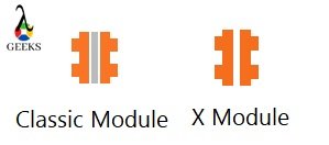
Tosca modules are classified into below two categories –

·        Classic Modules – It is created by classic engines during the scanning. 

·        XModules – It uses XEngines which are based on the Tosca TBox framework. 

tosca modules - icons
Icons of Tosca Modules

The each components of a module are known as ModuleAttributes and the components are known as controls. The Classic Modules have the classic ModuleAttributes, and on the other hand, the XModules have the XModuleAttributes.

Classic Engines: In the early phase of Tosca, Classic Engines are developed to processes the the TestCase information and steers the test object. There is respective engines are available to steer any test object.

TBox: The reference of Tosca Tbox framework algorithm is the basis for XEngines to steer any controls. Same can be applied to steer GUI and non-GUI objects.

XEngines: With the help of XDefinitions, the XEngines are defined in Tosca. The controls for the test objects are hierarchically structured through the XDefinition. So, the tree structure of the test objects are mapped with controls of any modules.

The Tosca TBox is compatible with the below engines:-

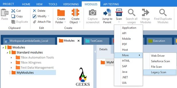
·        Tosca XScan 3.0 – After scanning the test objects (GUI or Non GUI), each time Tosca creates Modules which contains the technical properties. This technical properties are required to steer any test objects as controls. Scanning can be done from Modules sections only. So, modules are saved in “Module” section. We can scan any application by Right-clicking onto a Module folder and select the technology of the application such as, desktop, mobile, html, SAP, etc.

·        Tosca AnyUI Engine 3.0 –  It allows applications with user interfaces to be steered, independent of the underlying technology.

·        Tosca API Engine 3.0 –API Engine creates modules for application programming interfaces which is accessed through web service media.

·        Tosca Database Engine 3.0 – It allows to work with databases as a part of database automation.

·        Tosca DotNet Engine 3.0 – It allows WinForms applications to be tested that were built with Microsoft dotNET Framework 4.6.

·        Tosca Java Swing Engine 3.0 – It is used to scan the Java Swing applications for test automation.

·        Tosca JavaFX Engine 3.0 – It is used to scan the JavaFX applications for test automation

·        Tosca Java SWT Engine 3.0 – It is used to scan the Java SWT applications for test automation

·        Tosca JSON Engine 3.0 – JSON is the shorter form of JavaScript Object Notation which defines a compact format for data communication. Tosca JSON Engine is used to create, modify or verify the JSON.

·        Tosca Mobile+ Engine – It allows different types of mobile applications (e.g. web, native, hybrid apps) to be steered on both smartphones and tablets. For older version of android/ios, these engines are used for scanning.

·        Tosca Mobile Engine 3.0 – It is used to test mobile apps on both smartphones and tablets.

·        Tosca SAP Engine 3.0 – It is used to scan and test the SAP applications.

·        Tosca Webservice Engine 3.0 – Tosca Webservice Engine 3.0 allows Webservices to be steered via Hypertext Transfer Protocol (HTTP). Webservices using SOAP (Simple Object Acces Protocol) or REST Webservices (Representational State Transfer) can be steered.

·        Tosca XML Engine 3.0 – It is used to interact with XML data to change, create or verify the data.

What is the Standard Module?

With the workspace creation, Tosca provides few modules which are used to perform very common operations such that open file, invoke application, string operations, buffer operations, close application, verifications, etc. These modules are known as standard modules. The most important standard modules are – 

TBox Automation Tools:

  • · Basic Windows Operations
  • · Buffer Operations
  • · Expression Evaluation
  • · File Operations
  • · Folder Operations
  • · Numeric Operations
  • · Process Operations
  • · Resource Handling
  • · Selenium
  • · Timing

TBox XEngines:

  • · Parameter Data
  • · Database
  • · Html
  • · File, XML, JSON
  • · Mail
  • · Mobile
  • · SAP, Java
  • · Excel
  • · Pdf
  • · Host

Test Data Service:

  • · TestData – Find & provide record
  • · TestData – Create & provide new record
  • · TestData – Update Record
  • · TestData – Move record to TDS type
  • · TestData – Delete Record
  • · TestData – Update type
  • · TestData – Expert Module

Tosca Scan: 

Scanning through Tosca is an approach to create Tosca modules which contain all the technical information for any test application.

Step-by-step guide of Tosca Scan to create a module:

We can initiate Tosca scan either right-clicking on Module folder or selecting the dynamic menu Modules and click on Scan icon. In this application, we will learn the scanning with a sample web application. 

tosca modules - scan options
tosca modules – scan options

Tosca Scan – Classic Modules: 

Tosca wizard is a part Tricentis Tosca and used for classic scanning to create classic modules. Generally, for legacy applications which are not properly compatible for TBox Scan, we are using this approach of scanning. We can open the Tosca wizard as a standalone application from Start Menu or by selecting the option “Scan More->Legacy Scan” during scanning. Please click here to read more on this topic.

tosca modules - classic wizard
tosca modules – classic wizard
  • Main Navigation Panel – Shows the scanned controls.
  • Automation Property – Mandatary technical information about the selected controls.
  • Scan – Start scanning of the entire region.
  • Scan Region – Scan selected region.
  • Create Module – Save to create a module for the scanned region. Classic modules are looking like below image – 
tosca modules - custom classic module
tosca modules – custom classic module

Tosca Scan – Tbox Module:

Tosca XScan is a part Tricentis Tosca and used for TBox scanning to create Tbox modules. During the scanning, we need to select the engines based on the test application. Scanning steps – 

  • Step# 1: Go to Modules section and select scan path “ScanàApplication”.
  • Step# 2: Select the test application from “Application Selection” screen and click on Scan button.
  • Step#3: Xscan screen will be displayed. Here all the available controls are shown here along with technical properties of each of the controls. Based on the properties selected, the control is getting identified by Tosca. There are four different ways to identify the controls – 
    • Identify by Properties – Here based on the technical properties of the test object, controls are getting identified. Always we should prefer technical properties like name, id, class, test, inner text to recognize the controls in the application.If the properties are not enough to identify any particular controls, we should go for other “Identified by” options which are available in Tbox Scan.
    • Identify by Anchor – In this method, we need to identify the test object with the reference of any other object which was identified uniquely. It uses algorithm Shortest Path or Coordinate for referenced controls. Here, we need to follow the options after clicking on “Select on Screen” button.
    • Identify by Image – Based on the image view of the test object. We can allow Tosca to recognize the control. But this is not a preferred method, and it should have opted at the last when all other options are not able to recognize the test objects.
    • Identify by Index – Index is basically the number of occurrence of the test object. It’s denoted by numeric value, starting with 1.We can highlight the selected controls using the “Highlight selection” option. Also, we can directly select a control from the application itself by choosing the option “Select on Screen”. Once the object identifies uniquely, we need to click Save or Finish Screen icon (available in the left top) to create a module.
  • Step# 4: Click on “Finish Screen” to clear the current scanned information. After this, click on Start Screen option to start afresh scanning of a new page.
tosca modules - tbox scan properties
tosca modules – Identify by properties
tosca modules - tbox scan anchor
tosca modules – Identify by Anchor
tosca modules - tbox scan image
tosca modules – tbox scan image
tosca modules - tbox scan index
tosca modules – Identify by index
tosca modules - custom tbox module
tosca modules – custom tbox module

Conclusion

In this article of Tricentis Tosca Tutorial, we have covered about Tosca Workspace Creation so that we can start with working with Tosca Commander. Need more information, please click here to visit Tricentis Support portal.