39 Important VLSI, VHDL & Verilog Interview Q&A

IMG24 1024x398 1

VLSI, VHDL, Verilog Interview Questions

1. Give the full term of VHDL.

  1. Very High Definition Language
  2. Very High Speed Integration Hardware Description Language
  3. Very High Description Language
  4. Very High Speed Scaling Hardware Describing Language

Ans: 2) Very High Speed Integration Hardware Description Language

For basic VHDL Tutorials, Click Here!

2. What is the number of Metal Oxide Filed Effect Transistors are needed to construct a Bi-complementary metal Oxide Semiconductor NOR gate which have two input?

  1. 5 MOSFETs
  2. 6 MOSFETs
  3. 7 MOSFETs
  4. 8 MOSFETs

Ans: 3) 7 MOSFETs

“How a Logic gate is designed in VLSI?” Find the answer here!

3. What is the effect of ‘Delay’ if the power supply voltage gets increased?

  1. Increases
  2. Decreases
  3. Remains the same
  4. Delay has nothing o do with power supply.

Ans: 2) Decreases

4. Which is true about VLSI design?

  1. VLSI is a sequential process which has feedback loops.
  2. VLSI is a parallel process which has no feedback loops.
  3. VLSI is both sequential and parallel process that has feedback loops.
  4. VLSI is a sequential process which has no feedback loops.

Ans: 3) VLSI is both sequential and parallel process that has feedback loops.

For more details about Verilog Interview Questions and other topic like VLSI Design, Check this!

5. What is the use of CAD tools in VLSI design?

  1. It automates the VLSI design.
  2. It reduces the design cycle time.
  3. It reduces the chance of errors.
  4. All of the above.

Ans: 4) All of the above.

6. Which type of product is more suitable for FPGA based Design?

  1. Large scale product development.
  2. High Speed applications.
  3. Prototype development.
  4. Low power applications.

Ans: 3) Prototype development.

What is Verilog? What is system Verilog? and other Verilog Interview Questions and Answers are here!

7. What is the relation between interconnect delay and gate delay?

  1. The Relation is technology dependent.
  2. Gate delay always more than interconnect delay.
  3. Interconnect delay always more than the gate delay.
  4. They are same.

Ans: 1) The relation is technology dependent.

8. State True or False

Statement: For a Y chart, the details of design information increases when moved from the centre to the periphery.

  1. True
  2. False

Ans: (2). False

9. Why a short channel device is preferred?

  1. It is easier for fabrication.
  2. It has lower power consumption.
  3. It has high speed.
  4. It has better output characteristics.

Ans: 3) It has high speed.

10. Where does the subthreshold operation of MOSFET find applications?

  1. Memories.
  2. Charge coupled devices.
  3. Biomedical applications.
  4. None of the above.

Ans: 3) Biomedical applications.
IMG24

Make your First VHDL Project!

Click Here!

VLSI, VHDL, Verilog Interview Questions, Image – 1

11. What is the relation between the ON-resistance of MOSFET and gate to source voltage (Vgs)?

  1. ON-resistance linearly increases with Vgs.
  2. ON-resistance linearly decreases with Vgs.
  3. ON-resistance exponentially increases with Vgs.
  4. ON-resistance non-linearly decreases with Vgs.

Ans: 4) ON-resistance non-linearly decreases with Vgs.

12. What is the threshold voltage of an EMOSFET?

  1. Equal to 0 V.
  2. Less than 0 V.
  3. Greater than 0 V.
  4. None of the above.

Ans: 3) Greater than 0 V.

13. Find the odd one out.

  1. Channel length modulation
  2. Subthreshold Conduction
  3. Hot carrier effect.
  4. Body Effect

Ans: 4) Body effect. (All the other options are 2nd order effect).

14. How does doping density change for constant voltage scaling?

  1. Increases by a factor of s
  2. Increases by a factor of s2.
  3. Decreases by a factor for s.
  4. Decreases by a factor for s2.

Ans: 2) Increases by a factor of s2.

15. How does power dissipation occur for full scaling?

  1. Increases by a factor of s
  2. Increases by a factor of s2.
  3. Decreases by a factor for s.
  4. Decreases by a factor for s2.

Ans: 3) Decreases by a factor of s2.

16. How does power dissipation occur for constant voltage scaling?

  1. Increases by a factor of s
  2. Increases by a factor of s2.
  3. Decreases by a factor for s.
  4. Decreases by a factor for s2.

Ans: 1) Increases by a factor of s.

17. What is the main advantage of depletion load NMOSFET inverter over EMOSFET load?

  1. Less power dissipation
  2. Easier fabrication process
  3. Sharper Vtc transitions and better noise margins.
  4. None of the above.

Ans: 3) Sharper Vtc transitions and better noise margin.

18. Why is polysilicon used for the gate in MOSFET?

  1. Because it is a semi-metal.
  2. Because it has lattice matching with Silicone
  3. Because it is easier to fabricate.
  4. None of the above.

Ans: 2) Because it has lattice matching with silicone.

19. State True or False

Statement: In full scaling, the magnitude of the electric field is constant.

  1. True
  2. False

Solution: (1). True

20. Which of the given statement is true regarding a MOSFET inverter?

  1. One PMOSFET and one resistor are needed to implement a MOSFET inverter.
  2. One NMOSFET and one resistor are needed to implement a MOSFET inverter.
  3. Two PMOSFETs.
  4. Two NMOSFETs.

Ans: 2) One NMOSFET and one resistor is needed to implement a MOSFET inverter.

Image 23 1

Build your first Verilog project!

Click here!

VLSI, VHDL, Verilog Interview Questions, Image – 2

21. On which factors, the power dissipation of a CMOS inverter depends?

  1. Supplied Voltage.
  2. NMOSFET’s channel width.
  3. PMOSFET’s channel width.
  4. All of the above.

Ans: 1) Supplied Voltage

22. State True or False

Statement: The PMOS transistors act as Pull-up network in a CMOS inverter.

  1. True
  2. False

Solution: (1). True

23. Which of the following effect has no contribution to deviate the ideal situation of a current mirror circuit?

  1. DIBL effects.
  2. Threshold offset between two transistors
  3. Channel length modulation
  4. Imperfect geometrical matching.

Ans: 1) DIBL effects.

24. What does the ASIC cell library contain?

  1. The physical layout of the cells
  2. Routing model of the cells
  3. Timing model of the cells
  4. All of the above.

Ans: 1) Physical layout of the cells.

25. Why does lowest propagation delay occur through a gate?

  1. Due to – strong transistor, high temperature, high voltage.
  2. Due to – strong transistor, low temperature, high voltage.
  3. Due to – Weak transistor, high temperature, high voltage.
  4. Due to – weak transistor, low temperature, low voltage.

Ans: 3) Due to – Weak transistor, high temperature, high voltage.

26. Which of the following is true about VLSI logic design?

  1. VLSI minimizes the area and delay
  2. VLSI minimizes the area at the cost of delay
  3. VLSI maximizes speed by decreasing area
  4. VLSI minimizes delay by reducing the area

Ans: 2) VLSI minimizes the area at the cost of delay.

27. What is a hard macro?

  1. Flexible Block
  2. Fixed Block
  3. Flexible block with a fixed aspect ratio
  4. Flexible block with a flexible aspect ratio

Ans: 2) Fixed Block

28. State True or False

Statement: The full form of SPICE is – Simulation Program with Integrated Circuit Emphasis.

  1. True
  2. False

Solution: (1). True

29. What is the equivalent circuit for CMOS comparator?

  1. Uncompensated CMOS OPAMP.
  2. Compensated CMOS OPAMP.
  3. Partially Compensated CMOS OPAMP.
  4. None of the above is true.

Ans: 1) Uncompensated CMOS OPAMP.

30. What is the relation between the equivalent resistance of a switched capacitor and the clock frequency?

  1. The resistance is proportional to clock frequency.
  2. The resistance is inversely proportional to clock frequency.
  3. The resistance is proportional to the square of the clock frequency.
  4. The resistance is inversely proportional to the square of the clock frequency.

Ans: 2) The resistance is inversely proportional to clock frequency.
VLSi 1

30 Most important and frequently asked VLSI Interview Questions! Click Here!

VLSI, VHDL, Verilog Interview Questions, Image – 3

31. What is the relation between the equivalent resistance of a switched capacitor and the capacitance?

  1. The resistance is proportional to the capacitance.
  2. The resistance is inversely proportional to the capacitance.
  3. The resistance is proportional to the square of the capacitance.
  4. The resistance is inversely proportional to the square of the capacitance.

Ans: 2) The resistance is inversely proportional to the capacitance.

32. What is the condition for domination by Diffusion Current?

  1. Strong Inversion
  2. Weak Inversion
  3. Both Strong and weak inversion.
  4. Cannot be determined.

Ans: 2) Weak Inversion.

33. What is the condition for domination by Drift Current?

  1. Strong Inversion
  2. Weak Inversion
  3. Both Strong and weak inversion.
  4. Cannot be determined.

Ans: 1) Strong Inversion.

34. State True or False

Statement: In the cascode current mirror, the output resistance is increased.

  1. True
  2. False

Solution: (1). True

35. State True or False

Statement: A current mirror circuit can be used as a current amplifier by increasing the (W/L) ratios of the mirrored and source MOSFET

  1. True
  2. False

Solution: (1). True

36. Which connections of NMOS in PDN, help to realize the AND terms?

  1. Cascade Connection
  2. Anti – parallel Connections
  3. Series Connections
  4. Parallel Connections

Ans: 3) Series Connections

37. Which type of transistor can pass logic-high value perfectly, but not the logic-low value?

  1. NMOSFET
  2. PMOSFET
  3. CMOS
  4. None of the above

Ans: 2) PMOSFET

38. What is the minimum number of transistors needed to design an XOR gate?

  1. Three
  2. Four
  3. Five
  4. Six

Ans: 4) Six

39. Which type of logic design provides the minimum propagation delay?

  1. Emitter Coupled Logic
  2. Transistor Transistor Logic
  3. Register Transistor Logic
  4. Diode Transistor Logic

Ans: 1) Emitter Coupled Logic

40. State True or False

Statement: Dynamic CMOS logic operates using two non-overlapping clock pulses.

  1. True
  2. False

Solution: (2). False.

For more VLSI related topic and Verilog interview questions click here
Verilog HDL Using Xilinx: 17 Important Steps You Should Know

INST 1 1024x576 1 300x169 1

Topics for Discussion

A. Xilinx

B. Prerequisites for Verilog HDL Using Xilinx

C. Xilinx Installation process

D. Creating your first Verilog project with XILINX

XILINX

Xilinx is a USA based tech-company which provides programmable logic devices. We will use Xilinx’s software “ISE 14.7 Simulator to implement Verilog designs. Xilinx is also used for VHDL implementations. Though some of the coding structure of Verilog is same as VHDL, there are fundamental differences between them.

First of all learn Verilog! Click Here!

Prerequisites for Verilog using Xilinx

Before getting started with Verilog with Xilinx, there are some prerequisites for an user. They are listed below.

  • Must have some knowledge of digital electronics. At least bits of knowledge of basic logic gates and sequential circuits are required.
  • An uninterrupted internet connection is a must.
  • A healthy amount of free memory is required to run the software smoothly. At least 20 GB space is needed in your machine.
  • Create an account on Xilinx’s website with an accessible email-id. The license will be mailed in that email-id.
  • We are demonstrating this tutorial for windows only.   
What is VHDL? What is the difference between Verilog & VHDL?

Xilinx Installation Process

  • Step 1: Download the software from the internet. The link to download Xilinx is given below –

(It is a 6GB ZIP file, ensure internet connection and space) The link for windows –

https://www.xilinx.com/member/forms/download/xef.html?filename=Xilinx_ISE_DS_Win_14.7_1015_1.tar

There are other downloadable options available. You can choose according to your requirement and choice from the below given link.

https://www.xilinx.com/support/download/index.html/content/xilinx/en/downloadNav/vivado-design-tools/archive-ise.html

  • Step 2: Unzip the file. To unzip the file, right-click on the file, and there will be an option to extract all. After the extraction, the file name should be – ‘Xilinx_ISE_DS_Win_14.7_1015.1”.

Point to be noted – Both the download and extraction will need a lot of time depending upon internet speed and storage availability. The installation will require a lot of time too. So, don’t panic, be patient.

  • Step 3: Open the extracted file. There is a file named – ‘xsetup’. Double click on that file. It will start the installation.
INST 1 1024x576 1
Choose the ‘xsetup’ file, Verilog HDL
  1. There will be another pop-up, choose the ‘ISE WebPACK’ option to continue.
INST 2 1
Choose the ISE WebPack, Verilog HDL

It will start the final installation process.

  • Step 4: After the software gets installed in your PC, some tasks must be performed. Do these tasks carefully. Also, update the license from Xilinx. Those steps are given in the previous article; please check it out before we start with our first Verilog Project. The link is given below.

https://lambdageeks.com/vhdl-process-xilinx-guide/

Creating your first Verilog project with XILINX

We will first implement a simple AND gate model using XILINX. The logical representation of AND gate is Y = AB; A and B are the two inputs, while Y is the output. The truth table is given below.

ABY =AB
000
010
100
111
Verilog HDL – AND gate truth table
  • Step 1: Open the project navigator by double clicking the icon on the desktop.
  • Step 2: Go to ‘File’ and then ‘New Project’. File -> New Project
Image 1 1
File -> New Project, Verilog HDL, Image 1
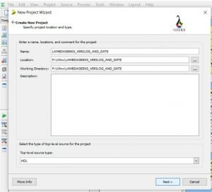
  • Step 3: Type a name for your project and select the storage location. It is advised not to use basic logic gate names as they are reversed keywords. Also, don’t forget to copy the name of your project; it will help your letter. Click on the ‘Next’ button to proceed.
IMAGE 2 1
Type a Name for the Project, and Choose Next, Verilog HDL Image – 2
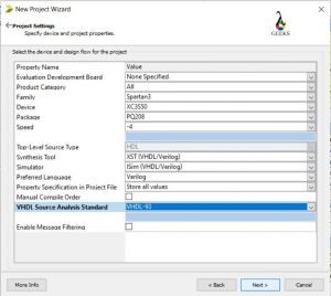
  • Step 4: Now, you have to set up a few things. Be careful while setting up all these things. Any mistake will lead to failure in the long-term result.
  • Property Name: Value
  • Evaluation Development Board: None Specified
  • Product Category: All
  • Family: Spartan3
  • Device: XC3S50
  • Package: PQ208
  • Speed: -4
  • Top Source Type: HDL
  • Synthesis Tool: XST (VHDL/Verilog)
  • Simulator: lSim (VHDL/Verilog)
  • Preferred Language: Verilog
  • Property Specification in Project File: Store all values
  • Manual Compile Order: Leave the checkbox, don’t click on it.
  • VHDL Source Analysis Standard: VHDL-93
  • Enable Message Filtering:  Leave the checkbox, don’t click on it.

Click on ‘Next’ to proceed.

Image 3 1
Do the setup carefully, Change the preferred language to ‘Verilog’, Verilog HDL Image – 3
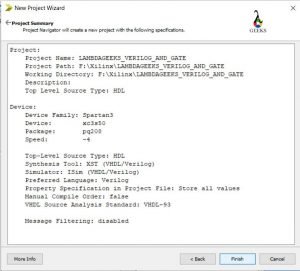
  • Step 5: Now, click on ‘Finish; for the next pop-up.
Image 4 1
Click on ‘Finish’, Verilog HDL, Image – 4
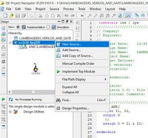
  • Step 6: A new window will be opened up in the ISE simulator. Inside the design tab at the left corner, and under the Hierarchy bar, the model will have appeared. Move your cursor on the folder just below the named model.

Then right-click on the folder (in our case the name of the folder is – ‘xc3s50-4pq208’). Then, select the new source.

Verilog HDL
Right Click and choose the ‘New Source’, Image – 5
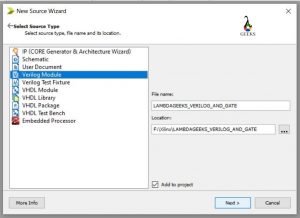
  • Step 7: In the new window, choose the ‘Verilog Module’ and paste the same name you have copied in the step 3. You can also get that name from the location tab. Click on ‘Next’ to proceed.
Image 6 1
Choose Verilog Module, Image – 6
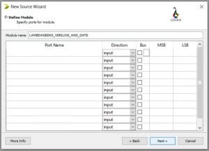
  • Step 8: The defining module will come up. But we will not define the ports now. Just click on ‘Next’.
Image 7 1
Click on NEXT, Verilog HDL, Image – 7
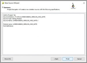
  • Step 9: Click on “Finish” for the next window pop-up.
Image 8 1
Click on ‘Finish’, Image – 8
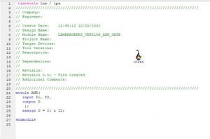
  • Step 10: A code editor will be opened up.
    • Now change the project name written in the editor to “AND”. For our case, we change it from ‘LAMBDAGEEKS_VERILOG_AND_GATE’ to ‘AND’.
Image 9 1
Rename the module in the editor, Verilog HDL, Image – 9
  • Now write down the port declarations as follow.

module AND (

                        input I1, I2,

                        output O

                        );

endmodule

  • Now assign the AND gate in-between the input and output.

assign O = I1 & I2;

Image 10 1
Write down necessary Verilog code, Verilog HDL, Image – 10
  • Save the code.
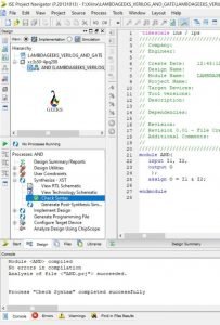
  • Step 11: Now, on the left side of the window, under the design bar, you can see a tab named “Process AND”.
    • Expand the ‘Synthesis – XST’ from there.
    • Double click on the ‘Check Syntax’. It will show a green tick, denoting success.
Image 11 693x1024 1
Complete the check syntax process, Verilog HDL, Image – 11
  • Step 12: Now again go back to the top-left section. Right-click  on the ‘xc3s50-4pq208’ file. Choose a new source from there.
Image 12 1
Add new source, Verilog HDL, Image – 12
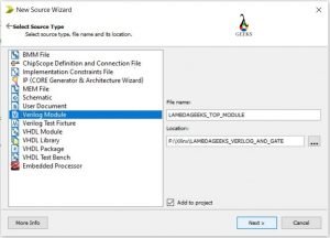
  • Step 13: Choose Verilog Module from the given list. Then put a file name. We put “LAMBDAGEEKS_TOP_MODULE” as the name. Click on the ‘Next’ to proceed.
Image 13 1
Choose Verilog Module, Verilog HDL, Image – 13
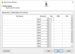
  1. A pop-up named ‘Define Module’ will come. Do not define anything here. Click on the ‘Next’.
Image 14 1
Click on Next, Verilog HDL, Image – 14
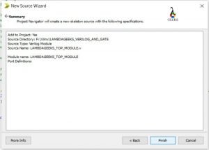
  • Click on ‘Finish’ for the next popped-up window.
Image 15 1
Click finish, Verilog HDL, Image – 15
  • Step 14: A code editor will be opened up. You can erase all the comment section from the code editor.
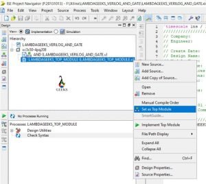
    • Now, check the Hierarchy Section at the top left. Right-click on the Module Name given by you. For our case, it is – ‘LAMBDAGEEKS_TOP_MODULE’.
    • Some options will come upon the right click. Choose the option – ‘Set as Top Module’.
Image 16 1
Select as Top Module, Verilog HDL, Image – 16
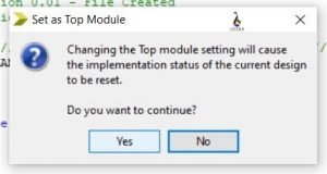
  • A window will pop-up. Click on ‘YES’ to continue.
Image 17 1
Click on Yes, Verilog HDL, Image – 17
  • Step 15: Now, we have to write some code using the code editor. It describes the input and output with the gate implementation. The following code is written for AND gate –

module LAMBDAGEEKS_TOP_MODULE(

            input I1, I2,

            output O

  );

            AND and1(I1,I2,O);

endmodule

Image 18 1
Write the corresponding Verilog Code, Verilog HDL, Image – 18
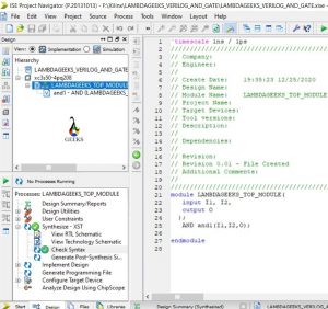
  • Step 16:  Now go to the left down part at ‘Process: LAMBDAGEEKS_TOP_MODULE’ section.
    • Now Expand the ‘Synthesis -XST’ part.
    • Double click on the ‘Check Syntax’. It will show a green tick denoting success after a few seconds.
    • Then, Double click on the ‘Synthesis – XST’ option. It will take a few seconds to show a green tick.
Image 19 1
Complete the check Syntax, Verilog HDL, Image – 19
  • Step 17:  View for RTL Schematic.
    • Double click on the ‘View RTL Schematic’ option.
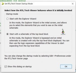
    • A window named – ‘Set RTL/ Tech Viewer behaves when it is initially invoked’ will pop up. Just click on the ‘OK’.
Image 20 1
Choose the second option, Verilog HDL, Image – 20
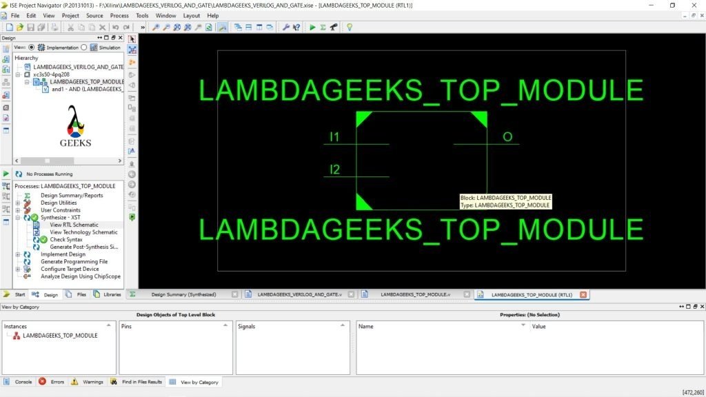
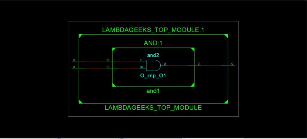
  • Now a window will be opened with a diagram.
Image 21 1024x576 1
Verilog RTL Schematic, Verilog HDL, Image – 21
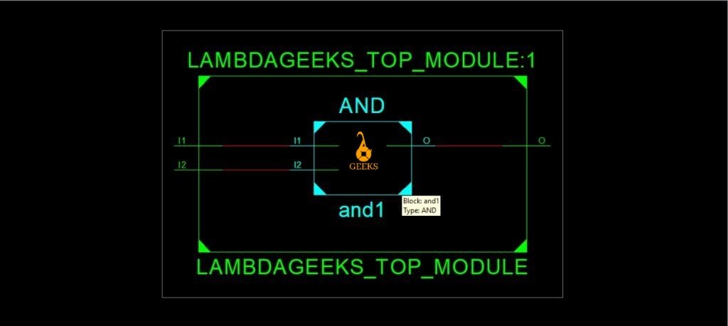
  • Double click inside the box.
Image 22 1024x459 1
Verilog RTL Schematic, Verilog HDL, Image – 22
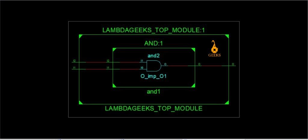
  • Now, double click inside the AND box.
Image 23 1024x466 1
Verilog RTL Schematic, Verilog HDL, Image – 23
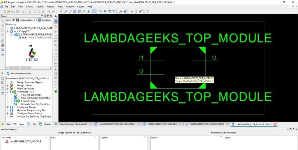
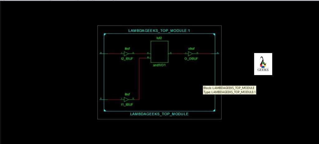
  • Step 18: View for Technology Schema
    • Double click on the ‘View technology Schematic’ option.
    • A pop-up will come to click on the ‘OK’ option.
Image 24 1024x609 1
Technology Schema, Verilog HDL, Image – 24
  • A new diagrammatic window opened up.
Image 25 1024x516 1
Verilog Technology Schema, Verilog HDL, Image – 25
  •  Double Click inside the box of the diagram.
Image 26 1 1024x464 1
Verilog Technology Schema, Verilog HDL, Image – 26
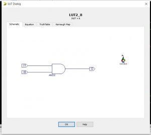
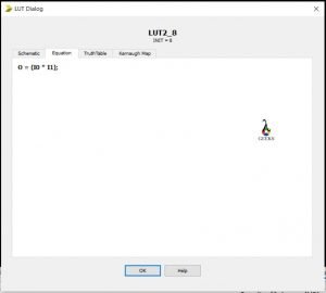
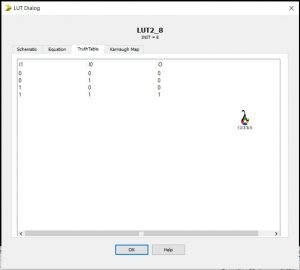
  • A box will be there named – ‘lut2’. Double click on that.

It will display several diagrams.

The schematic Diagram:

Image 27 1
Schematic Diagram
  • Click on the Equation to see the relation.
Image 28 1
Equation
  • Click on the Truth table to find the truth table.
Image 29 1
Truth Table
  • Click on the Karnaugh Map to find the Map.
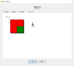
Image 30 1
K- MAP of AND gate

Check out our other VLSI articles!

Verilog Tutorial: 5 Interesting Facts To Know

verilog tutorials 0

Verilog Tutorial : Points of Discussion

  • What is Verilog?
  • History and Standardization
  • Verilog Design
  • Verilog Modelling
  • Verilog Operators

For others topic related to Verilog Tutorial, Click Here!

What is Verilog?

Verilog is the combination of the terms “Verification” and “Logic”. It is hardware description language or a special type of programming language which describes the hardware implementations of digital system and circuits. It is a strongly typed language and points to be remembered that it is not a programming language.

For step-by-step VHDL Tutorial, Click Here!

History and Standardization of Verilog

Prabhu Goel, Chi-Lai Huang, Douglas Warmke and Phil Moorby developed the Verilog around the year 1983-1984. The first name was “Automated Integrated Design Systems” which was further renamed as “Gateway Design Automation” and was purchased by Cadence in the year 1990. Cadence is now the copyright owner of Verilog and the Verilog-XL.

Primarily, the use of Verilog was to define and to start the simulation. Later the popularity of the language raised a demand for more development, and it leads to the synthesis of the logic circuits.

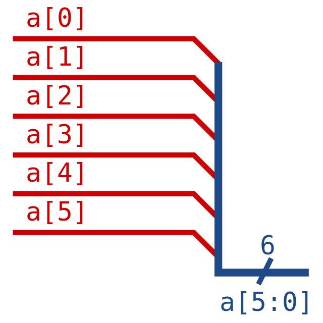
640px Verilog Bus.svg
Verilog Bus, Image Credit – InductiveloadVerilog Bus, marked as public domain, more details on Wikimedia Commons

Verilog Tutorial: Standardization

The popularity for VHDL forced cadence to publish the Verilog Language as open source. The first standardization of Verilog by IEEE was labelled as 1364-1995 and named as Verilog-95.

RevisionsUpdates
IEEE 1364 – 2001Verilog-2001. Supports signed variables and nest. Largely used by EDA packages.
IEEE 1364-2005Verilog 2005. Came up with little corrections and clarifications.
IEEE P1800-2005System Verilog.
IEEE 1800-2017Merger of SystemVerilog and Verilog. Known as SystemVerilog 2009.
IEEE Standardization of Verilog, Verilog Tutorial Table -1

Verilog Design

Verilog has two types of design methodologies. They are – Bottom-up approach & Top-down approach.

Bottom-up Approach: It is the conventional way of designing models. The planning is implemented at the gate level. Typical gates are used for implementations. This method opens up paths for different structural and ordered planning.

Top-down Approach: This approach has some advantages over the conventional one. Changes can be made easier here. Early testing is also possible.

Verilog Modelling

Verilog modelling has some design units. Let us discuss the primary components.

Verilog Code 1
Verilog Code for flip-flops

A. Module

A Verilog model comes up with port declarations, data type declarations, circuit functionality, timing specifications. A basic structure of the Module is given below.

module module_name (port_list);

<port_declarations>

<data_type_declarations>

<circuit_functionality>

<timing_specifications>

end module

  • Verilog is case sensitive.
  • Reserved keywords are written in lower cases.
  • A semicolon is used to terminate the statement.
  • The comment rule is same as C Programming Language.
  • Single line comment starts with “//”.

For example – //Example of a Verilog single line comment

  • Multiline comments start with – ‘ /*’  and ends with ‘*/’.

For example –

/* Example

Of Verilog multiple

Line comment*/

  • Timing specifications are used for the simulation process.

A module consists of a maximum of four levels of notion. The levels are defined below.

Behavioral: The highest level of notion. The anticipated design is planned at this level. Though, there is no thought for hardware implementations.

Dataflow: This level of Verilog Module describes the dataflow of the desired design. Hardware implementations of the dataflow through components are kept in mind while designing this level.

Image 26 1024x464 1
Dataflow Modelling, Verilog Tutorial

Gate: Logic gates are implemented in this Verilog module level. Interconnections are implemented between the gates.

Switch: The lowest level of notion. Switches, storage lumps are implemented. The interconnections are also designed between them.

B. Module Declarations

Module declarations start with ‘module’ keyword. It includes a port list (if exists).

Port types: There are three types of ports. The name and its functionality are given below.

  • input – input port
  • output – output port
  • inout – bi-directional port
Module Mixing 1
Verilog Code for Module Mixing, Verilog tutorial

Port Declarations: The general structure for port declarations is given below.

<port_type> <port_name>;

C. Data Types

There are several kinds of data types in Verilog.

 Net Data Type: This type of data describes the physical interrelate between flows.

Nets -> Functional Block: MUX -> Functional Blocks: Adders -> Nets

The below table will provide more details about Net Datatype.

TypeCharacterization
wireDescribes node or connections
triDescribes a tri-state node
supply0Represents Logic 0
suppy1Represents Logic 1
Net Data Types, Verilog Tutorial Table – 2
  •  Bus declarations: The general structure of bus declarations is given below.

<data_type> [Most Significant Bit (MSB): Least Significant Bit(LSB)] <signal_name>;

          <data_type> [Least Significant Bit(LSB): Most Significant Bit(MSB)] <signal_name>;

For example –

wire [3: 1] in;

Variable Data Type: This datatype describes the element to save a data for the time being.

There are many types of variable, supported by Verilog. Some of them are –

integer – 32 bits, Signed.

reg – any bit size, unsigned. To implement signed reg, use keyword – ‘reg signed’.

real, time, realtime – no support for synthesis.

D. Module Instantiation

After all the declarations, the module can be instantiated at a higher-level module with the help of some syntaxes. By instantiating modules, we can build designs with multiple levels of hierarchy. That will further help us to achieve simpler maintainability. Most of the modern designs have numerous layers of hierarchy.

The general format for instantiation is given below.

<componenet_name> #<delay> <instance_name> (port_list);

component name: It is the name of the module for the lower-level component.

delay: It is an optional choice. Delay introduces a delay throughout the component.

instance name: It is the exclusive name given by the designer for every individual instance.

port list: Port list gives the signal lists which will be connected to the component.

E. Simulation Component

After the designing process get completed, the testing process starts. This testing can be done using the stimulus block. Stimulus blocks are commonly known as a test bench.

Stimulus applications can be of two types. The primary design starts with the design block and directly drags the port signals into the design blocks.

The second design instantiates the stimulus block and the design block in a higher-level replica model. Interface is the communication link between the blocks.

Some Basic Verilog Concepts

Verilog Operators

Verilog has three fundamental operators for Verilog HDL. They are given below.

Unary Verilog operators : These types of Verilog operators come first of the operands.

For example: x = ~ y; Here ‘~’ is a unary operator

Binary Verilog operators : These types of Verilog operators come in-between two operands.

For example: x = y || z ; Here ‘||’ is a binary operator.

Ternary Verilog operators : These types of Verilog operators use two different operators to differentiates three operators.

For example: x = y?  z  : w; here ‘?’ and ‘:’ are ternary operators.

Verilog HDL’s categorical operators are – arithmetical, logical, relational, bitwise, shift, concatenation, and equality. Different types of Verilog operators and their symbols are given in the below table.

Type of OperatorSymbolOperationOperands needed
Arithmetic*MultiplicationTwo
Arithmetic/DivisionTwo
Arithmetic+AdditionTwo
ArithmeticSubtractionTwo
Arithmetic%ModulusTwo
Logical!negationOne
Logical&&ANDTwo
Logical||ORTwo
RelationalGreater thanTwo
RelationalLess thanTwo
Relational> =Greater than or equal toTwo
Relational< =Less than or equal toTwo
Equality==Equals toTwo
Equality! =Not equals toTwo
Equality===Case equalTwo
Equality! ==Case not equalTwo
Bitwise~NegationOne
Bitwise&Bitwise ANDTwo
Bitwise|Bitwise ORTwo
Bitwise^Bitwise XORTwo
Bitwise~^Bitwise XNORTwo
Reduction&Reduction ANDOne
Reduction~&Reduction NANDOne
Reduction|Reduction OROne
Reduction~|Reduction NOROne
Reduction^Reduction XOROne
Reduction^~Reduction XNOROne
Shift>> Right ShiftTwo
Shift<< Left ShiftTwo
Concatenation{ }ConcatenationCan be of any numbers
Replication{ { } }ReplicationCan be of any numbers
Conditional? :ConditionalThree
Verilog operators, Verilog Tutorial Table – 3

Verilog Operators has precedence also. Their Precedence is given in the below table.

OperatorSymbolsPrecedence
Unary Multiplication, Division, Modulus + ,-, !, ~ *, /, %Highest
Addition, Subtraction Shift+, – <<, >> 
Relational Equality<, <=, >, >= ==, !=, ===, !== 
Reduction     Logical&, ~& ^, ^~ |, ~| && || 
Conditional?:Lowest
Verilog Operator, Verilog tutorial table – 4

Verilog Number Specifications

Verilog numbers are of two types, sized numbers and unsized numbers.

Sized Verilog numbers: The general structure for representing sized numbers in Verilog HDL is given below.

<size>’<base_format><numbers>

For example – 8’b3456;

This is a sized Verilog number which describes that it is an 8-bit number and of binary type.

  • size: Size is the number of digits the main number has. Size is described using decimal values.
  • base_format: Base format suggests which type of number it would be. There are several types – binary (given by – ‘b’), decimal (given by – ‘d’), octal (given by – ‘o’), hexadecimal (given by – ‘h’). If there is no specification for base_format, then by default it is a decimal number.
  • numbers: The main number you want to put in.

Unsized Verilog numbers: These numbers do not require any specified size.

The general structure for representing unsized numbers in Verilog HDL is given below.

’<base_format><numbers>

For example – ’h3456;

This is an unsized Verilog number which describes that it is a hexadecimal number.

Negative Numbers: If you want to declare a number as a negative number, then put a minus symbol (-) before the number.

For example: – 345; it is a negative, unsized, decimal number.

Verilog Arrays

Arrays of integer, registers (reg), vectors ( of reg or net data types, several bit lengths) and time are possible in Verilog HDL. The basic declaration of arrays is shown below with an example.

integer matrix [0:3];

This means an array of seven values.

  • Verilog doesn’t allow any array for real variables.
  • Verilog HDL doesn’t support any multidimensional array.
  • Array elements can be retrieved using – <array_name>[<position_of_the_element>]

For others topic related to Verilog Tutorial, Click Here!

For step-by-step Verilog Tutorial using Xilinx, Check our next article!

Multiplexing: 7 Important Facts You Should Know

multiplexing 300x198 1

CONTENTS

  • What is Multiplexing ?
  • What are the types of Multiplexing ?
  • Time Division Multiplexing (TDM)
  • Descriptions of TDM
  • Frequency Division Multiplexing (FDM)
  • Descriptions of FDM
  • TDM vs FDM

What is Multiplexing ?

Define Multiplexing:

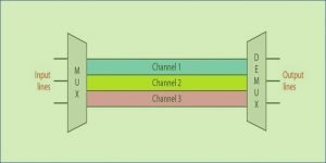
“Multiplexing is a method where many message signs are assembled into a composite signal for the purpose of transmission through a communication channel”.

These signals are transmitted through one communication channel. The signals have to be specified so that they do not interfere with one another, and they have to be separated in the receiver end again to recreate the original signal.

Multiplexing
Multiplexing, Image Credit – The AnomeMultiplexing diagramCC BY-SA 3.0

Multiplexing Techniques

It is of two types as follows:

  1. Time Division Multiplexing (TDM)
  2. Frequency Division Multiplexing (FDM)

Time Division Multiplexing:

What is TDM?

Time Division Multiplexing (TDM) is a technique in which a number of signals are made to pass through a common channel at different time slots.

Time Division Multiplexing (TDM)
Image credit: Tony R. Kuphaldt, Telephony multiplexer systemCC BY 1.0

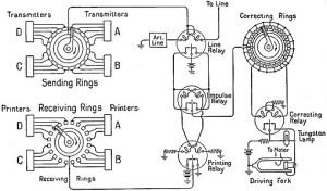
Diagram of TDM:

510px EB1922 Telegraph Simplified Terminal Circuit of Multiplex Printer System
Time Division Multiplexing in Telegraph, Image Credit – William Noble, EB1922 Telegraph – Simplified Terminal Circuit of Multiplex Printer System, marked as public domain, more details on Wikimedia Commons

Here, the TDM technique is employed to the three analog resources that are multiplexed through a PCM system. In practice, a digital switch is utilized for its sampler. This fs = 1/Ts represents the frequency of spinning to its sampler; also fs fits the Nyquist rate for its analog sources with the maximum selective bandwidth. In the certain process where the bandwidth of these is different, the bigger bandwidth resources could be linked to many switch places onto the sampler side to be usually sampled more than the shorter bandwidth input signal.

In the receiver, the sampler needs to be connected with the processed waveform, so the PAM samples corresponding to input one will show up on the channel just only output signal. This is known as ‘frame synchronization’. Lpf has been utilized to rebuild the analogue signals in the PAM samples. ISI resulting in bad channel filtering may induce PCM samples from one communication channel to look on other station, and frame synchronization condition has been maintained. The feedthrough of a one specific communication channel into the other channel is known as cross-talk.

Advantages and Disadvantages of TDM:

Advantages of TDM

  • Usually, TDM is more flexible than FDM.
  • The circuit design of TDM is not complicated.
  • In TDM, less cross-talk has occurred.
  • Channel bandwidth length is longer.

Disadvantages of TDM

  • Frequency Division Multiplexing process has no need of synchronization.
  • Implementation can be complex.

Applications of TDM

  • In ISDN (integrated service digital network), TDM is used.
  • In PSTN (public switched telephone network), TDM is used.
  • In a telephone system, TDM is widely used.
  • TDM is used in telephone wire lines.

Frequency Division Multiplexing:

What is FDM?

Frequency Division Multiplexing is a mechanism of signal transmission in which sharing the available bandwidth of a communication channel occurs among the signals to be transmitted.

In general, FDM schemes are utilized for the analog signal applications.

Diagram of Frequency division Multiplexing:

FDM
Frequency division Multiplexing

FDM is a method of transmitting many messages concurrently through a wideband by modulating the message signals on a few subcarriers and forming a composite baseband signal. This mixed signal is dependent on the quantity of those controlled subcarriers. This mixed signal could then be modulated by AM, DSB, SSB, PM, FM, as the primary types. The type of modulation used in the subcarriers may differ, and also the type used in carrier signal could also differ.

On the other hand, the mixed signal range should consist of inputs signal that should not possess overlapping spectra; otherwise, cross-talk will happen involving the receiver end’s message signals. The mix baseband signal subsequently modulates the transmitter to create the FDM signal sent across the wideband channel.

This FDM collected and demodulated to recreate the combination baseband signal filtered through filters and modulated subcarriers. The sub-carrier has to be demodulated to reproduce the message signals such as m1(t), m2(t) etc.

A speaker with a traditional monaural FM receiver may listen to that the audio sound (composed of the remaining – and the right-channel sound ). By comparison, a speaker with a stereo recipient will get the left-channel sound on the left speaker and the right-channel sound on the ideal speaker. The gap sound is used to govern a 38-kHz DSB-SC sign. Even a 19-kHz pilot tone has been mixed into the mix baseband signal mb(t) to supply a reference sign for coherent subcarrier demodulation in receiver end. As we all know, this program can be used with present FM monaural recipients.

Advantages and Disadvantages of FDM:

Advantages of FDM

· Between the transmitter and receiver, unlike TDM, FDM does not need any synchronization.

· Through FDM, a large number of signals can be transmitted simultaneously.

· Slow, narrowband fading can only affect one single channel.

· Demodulation of FDM is much easier comparatively than TDM.

Disadvantages of FDM

  • This suffers from cross-talk problem.
  • In this type Communication channel must have a large bandwidth.
  • In the technique, its channels get affected due to band fading.
  • In FDM intermodulation distortion takes place.

Applications of FDM

For more electronics related article click here
Phase Modulation And Frequency Modulation: Carson’s Rule

Define Angle or Phase Modulation:

“Angle modulation is a non-linear process and transmission bandwidth is usually much greater than twice the message bandwidth. Because of larger bandwidth, this modulation provides increased signal to noise ratio without increased transmitted power.”

Basically, angle modulation is divided into two categories namely Frequency Modulation & Phase Modulation.

One significant characteristic of  this type is that it can better classify in contrast to noise and interference signal than amplitude modulation. This adjustment in execution is accomplished in the expense of expanded transmission bandwidth; that is, this modulation gives us a method for improved signal to noise ratio.

Besides, this improvement in execution in angle modulation is achieved in the expense of complex circuitry in both the transmitter and receiver section and not possible in Amplitude one.

Mathematical Expression of Angle Modulation:

Let θi(t) signify the angle of a modulated sinusoidal carrier at time t; it is assumed to be a function of the information-bearing signal or message signal. The resultant angle-modulated signal is,

                                    s(t) = Ac cos [θi(t)]

Where Ac is the carrier amplitude, a complete oscillation happens each and every time the angle θi (t) will changed by the value of 2π radians if θi (t) increases with time, then the average freq in hertz, over a trivial intervals of t to t+∆t.

The angle-modulated signal s(t) as a rotating phasor of length Ac and angle θi (t) respectivelySuch a phasor’s angular velocity is dθi (t)/dt, measured in radians/sec. The angle θi (t) is represented for an unmodulated carrier signal,

                            θi (t) = 2πfct + kp m(t)

and the corresponding phasor rotating with a constant angular velocity measured in radians/sec. This constant specify the angle of the unmodulated carrier during that period.

There are various methods in which the angle θi (t) could be changed in a manner w.r.t to the message signal.

 Diagram of different waveforms of angle modulation:

Amfm3 en de
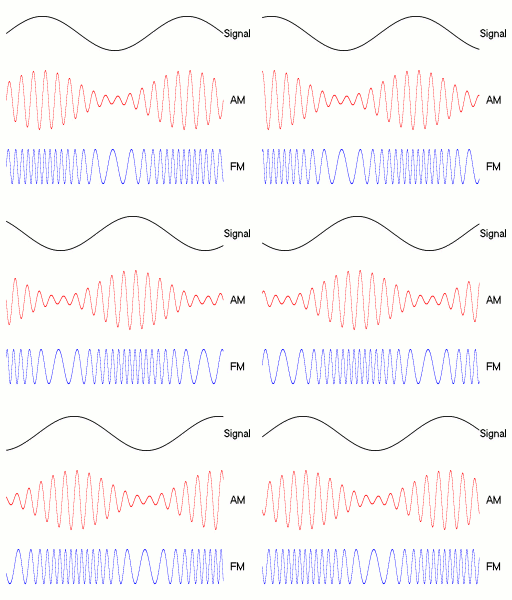
Diagram of AM, PM and FM waveform made by a single tone: a) the carrier wave   b) the amplitude modulated  c) the frequency modulated signal , Image Credit: BerserkerusAmfm3-en-deCC BY-SA 2.5

 Frequency Modulation:

Frequency Modulation is one form of angle modulation in that instantaneous freq of the carrier is changed  proportionally with the instantaneous amplitude variation of the modulating signal”.

FM is one sort of angle modulation in with  fi (t) is linearly proportional with the message signal m(t) as expressed below,

fi (t) = fc + kf m(t)

The steady value of fc presented to the frequency of the unmodulated carriers signal; the fixed kf termed as modulator’s ‘frequency-sensitivity factor’, measured in hertz per volt on the other hand m(t) is a voltage signal waveform. Integrating w.r.t time and multiply the result by a factor 2π, we can write

2 4

where the 2nd term for the increase or decrease in the instant phase θi(t) due to the message m(t) one. The frequency-modulated signal is consequently,

3 3

Phase Modulation:

Phase Modulation is such type of angle modulation in which the instantaneous angle θi(t)  is linearly proportional with the message ‘ m(t)’ signal as presented by means of,

                                 θi(t) = 2πfct + kp m(t)

The term 2πfct expresses to the un-modulated carrier angle  Øc set to ‘0’ in the phase modulation. The fixed kp value phase sensitivity factor of the modulator, communicated in radians/volt and m(t) is the voltage signal. In the phase modulation, modulated signal s(t) is correspondingly depicted in the time-space by,

                               s(t) = Ac cos [2πfct + kp m(t)]

Show that FM and PM are basically same:

Let the carrier signal is = Ac cos (2πfct)

Let the message signal is = m(t)

So, the expression of F.M. signal is =

4 3

Now if the modulation method is Phase Modulation. then the expression of Phase Modulation signal is

                              = Acos [2πfct + mp . m(t)]

Where, mp is a constant for the Phase Modulation

Also the Phase Modulation signal can be treated as a Frequency Modulation signal where message signal is dm(t)/dt.

So, basically Frequency Modulation and Phase Modulation are basically same.

Pre-Emphasis and De-Emphasis in FM:

A random undesired signal or noise constantly comes with a triangular spectral distribution in a Frequency Modulation technique, together with the impact that noise happens at the maximum frequency of baseband.

This may be offset, to some restricted selection, by raising the frequencies prior to transmitting and decreasing them with a corresponding receiver number. If we decrease the high frequencies from the receiver, then, in addition, it reduces the high-frequency noise.

These practice of increasing and decreasing of these frequencies are called pre-emphasis and de-emphasis, respectively. Most frequently 50 µs time constant is employed.

The total quantity of pre-emphasis which may be implemented is restricted by the simple fact that lots of kinds of modern sound signal comprise higher frequency energy compared to the musical styles that have predominated at the beginning of FM broadcasting.

They cannot be pre-emphasized since it might cause excess deviation. (systems more contemporary compared to FM broadcasting often utilize either programmed-dependent variable pre-emphasis.)

What is Narrow Band FM (NBFM) and Wide Band FM (WBFM ?

The expression for the FM signals is given by

5 2

and hence the instantaneous frequency ωi is given by,

6 1

where, kf = constant of proportionality and kr . em (t) represents the deviation of carrier frequency from the quiescent value ωc. Constant Kf hence controls the frequency deviation. If the Kf is small the frequency deviation is also small and the spectrum of the FM signal is having a narrow band. On the other hand, for higher value of kf, we get wide frequency spectrum corresponding to wideband FM case.

NARROW BAND FM:

The modulation index for narrow band FM is generally near unity and hence for this case, the maximum deviation δ<<fm and the bandwidth is

 B = 2fm.

This bandwidth is same as that occupied by AM signal. The narrowband FM is used wherein intelligible signals for communications are to be transmitted such as in mobile communication used by police, ambulance etc.

WIDE BAND FM:

The modulation index for wideband FM is greater than unity. The bandwidth of a wideband FM system is given by,

                                           B = 2(δ+fm)

For wideband FM δ<<fm and hence B =

Thus, the bandwidth of wideband FM is twice the maximum frequency deviation. The wideband FM is used where the purpose is to transmit high fidelity signals such as in FM broadcasting and TV sound.

For more Modulation And Demodulation related article click here
Modulation And Demodulation:Variants & Advantages

moddddddddd 1024x72 1

Definition of Modulation:

“Modulation is the process of requiring information contained a lower frequency electronic signal onto a higher frequency signal.”

The higher freq signal is named carrier signal and the lower freq signal is termed as the modulating signal.

The upside of sending the higher freq signal is multiple: Firstly if all radio broadcasts broadcast at sound frequencies, they couldn’t be recognized from each other, and just a mix or jumbled signal will be there. Second, it is discovered that specific antenna with a range of 5 miles to 5000 miles is essential for the audio transmissions.

The expression of the modulated carrier wave is,

                                            A sin 2πfct

If, for straightforwardness a particular audio signal is taken as the modulating signal, it can be characterized as,

                                      B sin 2πfat

The modulated signal may be represented by,

                                 (A + Bsin2πfat)(sin 2πfct)

                           V = Vc (1 + B/A sin2πfat) (sin2πfct)

Modulation Factor:

         m = The ratio of “peak value of the modulating signal” with ‘the peak value of the un-modulated signal”

Percent Modulation:

         M = B/A x 100

The modulation percentage may differ somewhere in the range of zero to 100 without distortion. When the per cent modulation is crossing 100 per cent,  noisy frequencies are mixed, and hence distortion is the result.

Types of Modulation:

There are mainly 2 modulation types,

  1. Analog modulation –  It’s a technique of transferring analog baseband signal like audio or TV signal over a higher frequency signal.
  2. Digital modulationthis is a digital technique of encoding digital info.

Again, Analog Modulation has different types; such as

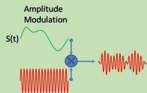
Amplitude Modulation:

“A modulation process in that amplitude of carrier is differed in agreement by means of the instantaneous value of modulating signal is termed as Amplitude Modulation”.

Regarding correspondences, an essential thing for modulation is to encourage the transmission of the data-bearing sign over a radio channel with a recommended passband. In continuous-wave modulation, this is made operational by amplitude or changing the angle of the sinusoidal carrier.

Definitions related to Modulation and Demodulation

Modulation Index of Amplitude Modulation:

Modulation index demonstrates what amount modulated variable of the carrier signal converted around its unmodulated level. In AM , this amount otherwise called modulation depth indicate how much the modulated parameter variable differs around its unique level.Mathematically modulation index is, ma, well-defined by,

moddddddddd

                                                      where, K = proportionality constant;

              Vm = amplitude of modulating signal;

              Vc = amplitude of carrier signal;

Angle Modulation

“Angle modulation is a non-linear process and transmission bandwidth is typically much more than the message band width.

Angle modulation is of two types. They are – Frequency Modulation and Phase Modulation.

A valuable component of angle modulation is that it can give better output in noisy and interference presence than AM technique. This improvement in execution is accomplished to the detriment of expanded transmission data transfer bandwidth; that is good methods for channel bandwidth with improved noise performance. 

Also, in angle modulation, the improvement in execution is possible at the expense of system circuit complexity in both the transmitter and collector. This is not possible in case of amplitude modulation technique.

Angle Modulation can further be divided into:

  1. Frequency Modulation:
  2. Phase Modulation:

Frequency Modulation

Frequency modulation is the form of angle modulation in which instantaneous frequency of the carrier is varied linearly with the instantaneous amplitude change of the modulating signal”.(link wiki)

FM Modulations
Michel Bakni creator QS:P170,Q81411358, FM Modulation – enCC BY-SA 4.0

Frequency Modulation has two important sections:

NARROW BAND FM:

Narrow band Frequency modulation has modulation-index around one. The greatest deviation is δ<<fm. The equation of bandwidth is given by the following equation. a

 B = 2fm.

WIDE BAND FM:

Typically the Wider Band Frequency modulation has modulation index greater than the one. The equation of bandwidth is represented in the following equation.

                                           B = 2(δ+fm)

For wideband FM δ<<fm and hence B =

Phase Modulation:

“Phase Modulation technique is an example for conditioning or tuning the correspondence communication signal for transmission.”

The period of a carrier signal is modulate to follow the changing sign degree of the message signal.

PM is the part of angle modulation where the θi (t) directly proportional to message signal m(t) as appeared by,

                                 θi(t) = 2πfct + kp m(t)

Digital Modulation can further be divided into:

  1. ASK (Amplitude Shift keying)
  2. FSK (Frequency Shift Keying)
  3. PSK (Phase Shift Keying)

What is Demodulation?

Definition of Demodulation:

Demodulation is basically extracting the original information carrying signal from a carrier wave.

Where as a demodulator is an circuitry that is utilized to recover original information or data from the modulated signal.

Some important demodulators (detectors) used for demodulating are:

  • Square law demodulator
  • Envelope detector

There are different demodulation techniques available dependent on the base-band signal parameters, for example,  amplitude, freq or phase angle are transmitted in the carrier signal.  A synchronous detector could be utilized when a signal is modulated with a linear modulation technique. In contrast, a Frequency modulation demodulator or a Phase modulation demodulator can be utilized for a signal attuned with a unintended one.

Comparison between Modulation and Demodulation:

                           MODULATION                      DEMODULATION
This is the process of influencing data information on the carrier. This is the restoration of original information as collected from the carrier. 
In modulation, unique message signal is at all times mixed with carrier signal whose parameters are required modifications In the demodulation technique, the mixture of carrier and message signal is detached from each other, to produce actual signal.
Modulation prerequisites a modulator for the mixing of the two signals. Demodulation prerequisites demodulator to recuperate the original signal. 
Modulation is for transmit data to extensive distance. Demodulation is utilized to regain the original message signal.
Modulation is comparatively simple in between Modulation and Demodulation technique.. Demodulation is comparatively complex in between Modulation and Demodulation technique.
This image has an empty alt attribute; its file name is modulation-and-demodulations.jpg
Modulation And Demodulation
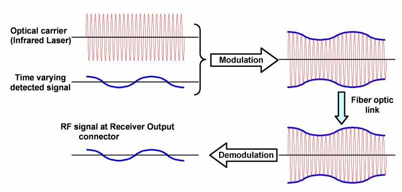
Image Credit : Calzavara S.p.a., Optical modulationCC BY-SA 3.0

For more Modulation And Demodulation related article click here
31 VLSI Interview Questions & Answers With Solution Tips

PLA VS PAL 300x99 1

VLSI is one of the most trending technologies in this digital era. Some of the frequently asked and important VLSI interview questions are given below for preparations. Study them for good result. To build up a solid concept on VLSI and VHDL, go through our detailed guideline -listed below. VLSI Interview Questions. Best of luck for your interview!

1. What is the range of integration can be designed using VLSI technology?

Ans: VLSI technology can incorporate ICs in a range of 2000 to 20,000.

2. What is Moore’s law?

Ans: Moor’s law is one of the most significant statements that describes large-scale integration technology growth. Gordon Moor, the co-founder of Intel, predicted that the number of transistors inside an integrated cheap would be doubled every 1.5 years.

3. What is BiCMOS?

Ans: BiCMOS is one of the kinds of integrated circuits that use Bipolar Junction Transistors and CMOS to design models.

4. What is Y- Chart?

Ans: Y chart is an illustration for the representation of IC design domains. Gajski-Kuhn introduced it.

5. Name the components of FPGA architectures.

Ans: FPGA or Field programmable gate array is a specially designed integrated circuit. The interconnections are programmable to design different logics. FPGA architecture consists of –

  1. Logic block array (CLBs)
  2. Input-Output Buffers
  3. Programmable Interconnections

6. What is PLA and PAL? Write some differences between PAL and PLA.

Ans: PLA is acronym of Programmable Logic Array, and PAL is acronym of Programmable Array Logic. They are kinds of programmable logic devices.

PLA VS PAL
PAL vs PLA, VLSI Interview Questions

7. What is the condition for a CMOS inverter to be a symmetric CMOS inverter?

Ans: The logic voltage for a symmetric CMOS inverter will be equal to half of the supplied voltage (VDD).

VINV = VDD / 2

8. Name and explain the design rules of VLSI technology.

Ans: There are two types of design rules – Micron rules and Lambda rules.

Micron Rules: This rule deals with some of the important parameters like – min. sizes of features, permissible feature separations, etc.

Lambda Rules: The Lambda is the primary length unit.

Check this article for more!

9. What is Antenna Effect regarding VLSI technology?

Ans: While the fabrication of interconnection is under process, some of the metal lines may be partially processed. Those metal lines further gather static charges inside the clot surroundings. Later, if those lines get interconnected with transistors, the previously stored charges may start discharging during operation in progress. That discharging may affect the gate oxide. This effect is known as Antenna Effect.

10. What is PLL?

Ans:  PLL is Phase Locked Loop, which can track the frequency- coming inside. PLL can also work as a clock generator.

11. What is PDN and PUN?

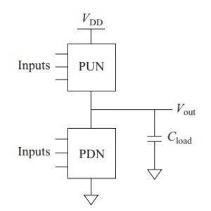
Ans: PDN is Pull Down Network, and PUN is Pull Up Network. They are used to design desired CMOS logic.

12. Which type of transistors are used in Pass Transistor Logic?

Ans: Pass transistor logic uses NMOS transistors to design models.

13. What is Domino CMOS logic?

Ans: Domino CMOS logic is implemented by connecting a static CMOS inverter at each dynamic CMOS logic’s output.

14. What is the full form of VHDL?

Ans: VHDL stands for – Very High Speed Integrated Circuit Hardware Description Language or VHSICHDL.

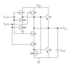
15. How many MOSFETs and BJTs are required to design a BiCMOS two-input NAND gate? Draw the circuit diagram of a two-input BiCMOS NAND gate.

Ans: To build a BiCMOS two-input NAND gate, we need 7 MOSFETs and 2 BJTs.

BiCMOS NAND GATE
BiCMOS NAND Gate, VLSI Interview Questions

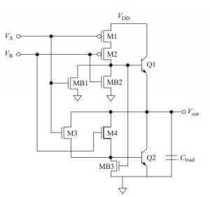
16. How many MOSFETs and BJTs are required to design a BiCMOS two-input NOR gate? Draw the circuit diagram of a BiCMOS NOR gate.

Ans: To build a BiCMOS two-input NOR gate, we need 7 MOSFETs and 2 BJTs.

BiCMOS NOR GATE
BiCMOS NOR Gate, VLSI Interview Questions

17. What is ROBDD and OBDD?

Ans: OBDD is an Ordered Binary Decision Diagram, and ROBDD is Reduced Ordered Decision Diagram. These are Boolean space methodology for handling a large number of input signals.

18. Give some examples of Logic Synthesis Techniques of VLSI design.

Ans: Some of the logic synthesis techniques are – Instantiation, Macro expansion/ substitution, Inference, logic optimization, and structural reorganization.

19. What do you mean by Local-skew, Global Skew?

Ans:

Local Skew: Local skew is the change of clock to reach the launching flip-flop to reach the destination flip-flop.

Global Skew: Global skew is the alteration of first reaching flip-flop to the last reaching flip-flop.

20. What is FSM or Finite State Machines? Discuss the types of FSM.

Ans: FSM or Finite State Machines are devices consists of both combinational and sequential logic circuits. Input signals and current states help the machine to change its state.

The two kinds of Machines are –

  • Moore Machine: The FSM whose outcome is contingent upon the present state of the machine.
  • Mealy Machine: The FSM whose outcome is contingent upon the present state of the machine as well as upon the input signals.

21. What is HBM or Human body model regards to VLSI?

Ans: HBM or Human Body Module is a corresponding course to describe the electrostatic discharge models when the IC is in direct contact with the human figure.

22. What is Soft Error? What is SER?

Ans: Soft error occurs due to the striking of charged particles against the semiconductor devices. It can be described as a type of noise r glitch.

SER or Soft Error Rate is the prediction rate of a device to face a soft error.

23. Compare between FPGA and ASIC.

Ans: The comparative study between FPGA and ASIC is given in the below table.

Subject of ComparisonFPGAASIC
NAMEField Programmable Gate ArrayApplication Specific Integrated Circuit
ApplicationThe user designs the program on his ownThe user gives the description of the need; the vendor provides the required model.
Production Set-up CostsMinimal production set up cost.Relatively costlier
Turnaround TimeFaster Turnaround TimeSlower turnaround time
CapabilityLower CapabilityHigher capability and efficiency for a higher volume of production.
VLSI Interview Questions

24. What are the modes of SFF or Scan Flip Flop?

Ans: SFF or scan flip-flop has two types of operation modes. In the general model, the flip-flop function as conventional flip-flops. In the next mode or the scan mode, the flip-flops are connected so that they will work as a series of registers.

24. What is AD HOC testing?

Ans: AD HOC testing is a strategy or process to condense the number of trials from a huge set of test outlines.  It is most useful for small models where ATPG, BIST are not available.

25. What is BIST?

Ans: BIST is a Built-in self-test. It is a testing logic circuit that is placed inside a chip. BIST consists of – PRSG or pseudo-random sequence generator and signature analyser.

26. Describe Slew Balancing.

Ans: Slew is a basic term related to the rise and fallen time of the input and output waveforms. Rise time is known as rising slew, whereas fall time is known as fall slew. Slew balancing is the process of making the rise slew and fall slew equal. To do so, the corresponding resistances of the transistors are kept equal.

27. Why CMOS is preferred over BJT in VLSI designs?

Ans: CMOS technology is preferred over BJTs for VLSI designs. Some of the reasons are –

  • CMOS has lower power indulgence.
  • CMOS uses lower area
  • Scaling of CMOS is easier than that of BJTs.
  • CMOS has a lower fabrication cost.

28. State some of the DSM issues.

Ans: Some of the DSM or deep sub-micron issues are – interconnect RC delays, IR drop, induction effects, antenna effects, capacitive and inductive coupling, etc.

29. What is the package of VLSI design?

Ans: Package: It is basically the storage of various datas. VHDL packages typically made up of Declaration and Body of the packages.

30. What are the future technologies of VLSI?

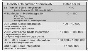
Ans: Future technologies of VLSI are – ULSI (Ultra Large Scale Integration) and GSI (Giga- Scale Integration). ULSI has a range of – 100,000 gates to 1,000,000 gates per IC, and GSI has a range greater than 1,000,000 gates per IC.

For more Electronics related article click here
VLSI Design Flow Of Logic Circuits & 5 Important Facts

VLSI Design Flow 1 245x300 1

Introduction to VLSI Design Flow

In the previous article, we have got an overview of VLSI design flow. In this article, we will learn about how different logic circuits can be implemented using VLSI design. VLSI is one of the key technologies in this era of digitalization. Transistors are used to implement logic circuits in VLSI design.

Digital logics are three types – the Inverter of the NOT gate, the AND gate, and the OR gate. More complex gates like -NAND, NOR, XNOR, and XOR can also be made using the basic gates. Let us discuss some of the methods of implementation of logic circuits.

CMOS Logic Design

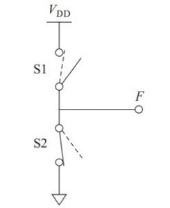
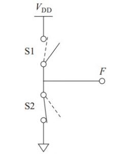
Digital is everything about ZERO and ONE or HIGH or LOW. The input for a digital logic circuit will be either 0 or 1, so as the output value. Now, if a circuit takes input as 0 and 1, then the logic can be understood by the switch function as given-below.

VLSI Design Flow
Switching Operation for VLSI Design Flow

We can see in the image that when the s1 switch is opened and the s2 switch is closed, then the output will be 0; for vice versa, the output will be 1.

VLSI Design Flow 2
Complementary Push-Pull structure, VLSI Design Flow
VLSI Design Flow 3
A CMOS logic implementation; PUN – Pull Up Network; PDN – Pull Down Network, VLSI Design Flow
For Complete VHDL Tutorial! Click Here!

CMOS Design Methodology

There are three steps for designing a CMOS logic as a part of VLSI design flow.

  1. Find out the complement of the Boolean Expression you need to implement.
  2. Describe the PUN
  3. Describe the PDN

The Pull Up Network Design:

Multiplying terms: NMOSFETs in parallel connection

Additive Terms: NMOSFETs in series connections

The Pull-Down Network Design:

Multiplying terms: NMOSFETs in series connections

Additive Terms: NMOSFETs in parallel connections

Design Your First VHDL Model using Xilinx. Click here for step by step guide!
CMOS Inverter / CMOS NOT Gate Design

A digital inverter is a NOT gate that gives the inverted output for an input. For high input or input is digital ONE, then the output is low or digital ZERO. For low input or input is digital ZERO, then the output is high or digital ONE.

INPUTOUTPUT
HIGHLOW
LOWHIGH
NOT gate truth table / Inverter truth table, VLSI Design Flow

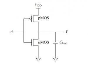
A CMOS inverter is made of two enhancement-mode transistors – one is NMOS, and the other is PMOS. The NMOS works as a pull-down network, and the PMOS works as a pull up network. The input voltage controls both the transistors.

When the PMOS transistor is in the ON state, the NMOS transistor goes into the OFF state. Also, when the NMOS transistor stays OFF, the PMOS will be in an ON state. That is how both the transistors work in complementary mode.

The transistor, which remains in OFF state, provides a high impedance value, and the output value changes. Under the same rail, a CMOS logic-circuit has less noise than an NMOS logic-circuit.  

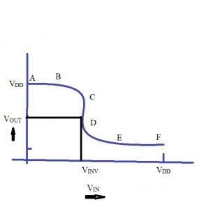
The graph of the voltage transfer characteristics of a symmetrical CMOS is given below.

Voltage Transfer Charecteristics
Voltage transfer characteristics of a symmetrical CMOS, VLSI Design Flow

Operation

The transistors are made in such a way that their threshold voltages should be of equal magnitude and opposite polarity. That is, the threshold voltage of NMOS will be equal to the magnitude of the threshold voltage of PMOS, given by the below expression.

VTN = – VTP

When the input voltage (Vin) is smaller than the threshold voltage of the NMOS transistor, then the NMOS transistor is in an OFF state. Then, the PMOS circuit will control the output voltage (Vout) with the supplied voltage (VDD). The AB region of the graph represents this operation.

Now, when the input voltage is greater than the difference of VDD and threshold voltage, then the PMOS logic circuit enters into an OFF state, and the NMOS gets activated. Then, NMOS controls the output voltage (Vout) with the ground voltage that is 0 V.

The graph’s BC region represents the saturated NMOS, and the CD part represents both the transistors are in saturated mode. VINV is the input voltage value for which the input voltage equals the output voltage.

From careful observation, we can say that the change is very high-pitched for the voltage swipe from 0 to VDD. That is why the CMOS inverter is a perfect inverter for logic design.

Now, when the input voltage is equal to the VINV, both the transistors are in saturation. The pull up network (PUN) will have VGS value =

VGS = Vin – VDD

Or, VGS = VINV – VDD 

Current equation for saturation region is given as –

ID = μεW * (VGS – VTH )2 / 2 LD

This equation can be rewritten for pull up network–

 IDpu = μpεWpu * (VINV – VDD   – VTHP)2 / 2 D Lpu

The equation for pull down network will be –

IDpd = μnεWpd * (VINV – VTHN )2 / 2 D Lpd

Equating the drain current as per the characteristics –

μnεWpd * (VINV – VTHN )2 / 2 D Lpd = μpεWpu * (VINV – VDD   – VTHP)2 / 2 D Lpu

or, VINV – VDD   – VTHP = – β (VINV – VTHN) ; [ β = (μn * Zpu / μp * Zpd) ½]

Or, VINV = (VDD + VTHP + β * VTHN) / (1 + β)

If VTHN = – VTHP, then β comes as 1.

Furthermore, VINV comes as VDD/ 2 and

Zpd : Zpu = μn : μp =~ 2.5 :1

Power Dissipation

CMOS logic-circuits dissipate less power than that of an NMOS logic-circuit for low frequency. The CMOS power degeneracy swings as per the switching frequency of the circuit.

Noise margins

Noise margin is the maximum allowable deviation that can be occurred without changing the main feature under noisy conditions. NML is given as the difference between the logical threshold voltage and the logic ZERO equivalent voltage for a CMOS inverter of low level. The noise margin is described as the difference between the logic high or ONE equivalent voltage and the logical threshold voltage for the high level.

CMOS two input NAND and NOR gates

NOR and NAND gates are known as universal logic gates, which can be used to implement any logic equation or any kind of other logic gates. These are the two most manufactured gates using the CMOS logic for VLSI technology. Let us discuss the implementation and design of both the gates using CMOS logic.

CMOS NOR gate

A NOR gate can be described as an inverted OR gate. The truth table of the NOR gate is given below, where A and B are the inputs.

NOR GATE TRUTH TABLE 1
NOR Gate Truth Table, VLSI Design Flow

A NOR gate can also be implemented using CMOS technology. The CMOS inverter circuit comes into work in this design. A pull-down network (transistor) is added with the basic CMOS NOT gate in a parallel connection to implement the NOR operation. For two input NOR gates, only one pull-down network is added. To incorporate more numbers of inputs, more transistors are added.

Operation

The logic implementation using CMOS is shown in the below image. When any of the inputs is logic high or logic ONE, then the pull-down way to the ground is locked. The output will be logic ZERO.

When both the inputs get HIGH voltage or logic – ONE value, then the output value will be logic high or ONE. The logical threshold voltage will be equal to the threshold voltage of an inverter. That is how NOR logic can be achieved using CMOS.

PMOS NOR gate
PMOS NOR Gate, A & B are the inputs, Y is The Output; VLSI Design Flow, Image Credit – KenShirriffPMOS-NOR-gateCC BY-SA 4.0

CMOS NAND gate

A NAND gate can be described as an inverted AND gate. The truth table of the NAND gate is given below, where A and B are the inputs.

NAND GATE TRUTH TABLE
NAND gate truth table, VLSI Design Flow

A NAND gate can also be implemented using CMOS technology. The CMOS inverter circuit also comes into work in this design. A pull-down network (transistor) in series and a depletion mode transistor are added with the basic CMOS NOT gate to implement the NAND operation. For two input NAND gates, only one transistor is added. To incorporate more numbers of inputs, more transistors are added to the series connection.

Operation

CMOS NAND
CMOS NAND Gate, VLSI Design Flow; Image Credit – JustinForceCMOS NANDCC BY-SA 3.0

The logic implementation using CMOS is shown in the above image. When both the inputs are logic ZERO, both the NMOS transistors are in OFF state, while both the PMOS transistors are in ON state. The output gets connected to VDD, and that is how the output provides logic ONE or high value.

When input A gets a high value as input, and the input B gets a low value, the upside NMOS goes into ON state, and lower NMOS goes into OFF state. The ground connection cannot be established with the output value. In this condition, the left PMOS gets ON, whereas the right PMOS stays in the OFF state. The VDD finds a path through output and provides a high output value or logic 1.

When input B gets a high value as input, and input A gets a low value, the upside NMOS goes into OFF state, and lower NMOS goes into ON state. The ground connection cannot be established with the output value. Also, in this condition, the left PMOS gets OFF, whereas the right PMOS goes into the ON state. The VDD finds a path through output and provides a high output value or logic 1.

For the final logic, when both the input gets high input voltage or logic ONE value, both the NMOS transistors are in ON state. Both the PMOS transistors are in OFF state, providing a path for the ground voltage to connect with the output. The output thus provides logic ZERO or low value as output.

For more Electronics related article and VLSI design flow click here
VLSI: Definition,Design,Important Rules And Scaling

750px Moores Law Transistor Count 1970 2020 300x222 1

A. What is VLSI?

To know about VLSI, we have to know about IC or integrated circuit. An IC is a chip or a processes package which contains transistors or digital circuits in lakhs of number.

VLSI or very large scale integration refers to the process to incorporate transistors (especially MOS transistors) to formulate IC.

VLSI devices consist of thousands of logic gates. They help to create big memory arrays .The arrays are used in microcontroller and microprocessors. It is possible to incorporate 104 to 109 components in a single chip in standard VLSI designing technique.

B. History and background of VLSI

The very first transistor was invented in the year 1947 by J. Barden, W. Shockley, W. Brattain in the Bell Laboratories. All three scientists got noble for the invention in the year 1956. The transistor size got reduced with progress in time and technology.

Jack Kilby and Robert Noyce came up with the idea of IC where components are connected within a single chip. This helped engineers to increase the speed of the operation of various circuits.

Moor’s Law: In the year 1998, Intel Corporation’s co-founder Gordon Moor predicted a trend on the number of components in an integrated circuit.

He predicted that –

“The transistor number inside a microchip gets doubled in every two years”.

The trend is followed with some exceptions.

750px Moores Law Transistor Count 1970 2020
Graph showing how the world has followed Moor’s Law, Image Credit – Max Roser, Hannah Ritchie, Moore’s Law Transistor Count 1970-2020CC BY 4.0

The progress of integrated circuits leads to the discovery of very large scale integration or VLSI technology. Before the VLSI get invented, there were other technologies as steps. They are discussed below.

  • SSI or Small Scale Integration: These type of integrated circuits contains less than ten logic gates. These IC gates have several gates or flip-flops associated with one package.
  • MSI or Medium Scale Integration: These packages contain ten to thousand logic gates. MSI ICs can generate basic logic gates. The logic gates can be further used for making sequential and combinational circuits like – mux-demux, encoders-decoders, latch, flip flop, registers, etc.
  • LSI or Large Scale Integration: LSI units contain more than one hundred gates. LSI ICs creates more complex circuit structures like – calculators, mini-computers, etc.
  • VLSI or Very Large Scale Integration: Contains thousands of logic gates.
  • ULSI or Ultra Large Scale Integration: A single chip contains more than 10^9 components.

An overview of transformation is given below.

VLSI DIFFERENT SCALINGS
Different range for scale-integration design (in standard VLSI design > 10000 gates per IC are used )

Click here to know about VHDL Designs!

C. VLSI Design

A VLSI design has several parts. It needs right and perfect physical, structural, and behavioural representation of the circuit. Redundant and repetitive information is omitted to make a good artwork system. It is achieved by using graphical design description and symbolic representation of components and interconnections.

VLSI architectures use n-channel MOS field-effect transistors and complementary MOS. Complementary MOS or CMOS need both the n-channel and p-channel MOS FETs to be fabricated in the same substrate.

In the 1980s, the demand for increasing package density grew up, and it affected the power consumption of NMOS ICs. The power consumption became so high that the dissipation of the power posed a serious problem. To resolve the issue, the CMOS technology emerged as a solution.

CMOS provides high input impedance, high noise margin, and bidirectional operation. That is why it works smoothly as a switch.

Implement VHDL using Xilinx… Start Making your First Project here!

D. Transistors in VLSI Design

The Metal Oxide Semiconductor Field Effect Transistor or MOSFET is the key component in high-density VLSI chips.

Why is FET used in VLSI?

FET or Field Effect Transistors are probably the simplest forms of the transistor. FETs are used widely in both analogue and digital applications. They are separated by a large value of input resistance and smaller area and size, and they can be used to form circuits with low power consumption. That is why they are widely used in very large scale integration.

CMOS and n-channel MOS are used for their power efficiency.

Characteristics of NMOS Transistors

1024px IGFET N Ch Enh Labelled.svg 1
Symbolic representation of NMOS FET, Image Source – anonymous, IGFET N-Ch Enh Labelled, marked as public domain, more details on Wikimedia Commons

An NMOS field effect transistor is shown in the above image with the drain current and terminal voltage representations. For an NMOS FET, the source and drain terminals are symmetrical (bidirectional).

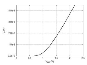
When there is no charge on the gate terminal, the drain to source path acts as an open switch. As a thin oxide layer separates the gate from the substrate, it gives a capacitance value. When the gate terminal accumulated enough positive charges, the voltage VGS exceeds a threshold voltage VTH. Thus, electrons are attracted in the region under the gate to give a conducting path between the drain and the source.
The gate voltage enhances the channel conductivity by entering into the enhancement mode operation. VTH ~= 0.2 VDD gives the VTH.

The majority carrier for this type of FET is holes. When the positive gate to source voltage or VGS is smaller than VTH, the majority carrier or holes are repelled into the substrate. Now, on the surface of the p-type there is no carrier. There is no current because of the depletion region.
Now, when the gate to source voltage get higher than the threshold voltage, a healthy amount of minority carriers gets attracted to the surface (Which in our case is the electron). Thus, a channel is formed of inversion layer between the source and drain terminal. 

The below expression gives the drain current ID.

ID = Charge induced in the channel (Q) / transit time (τ)

The charge transit time τ is the time taken by a charge carrier to cross the channel from the source terminal to drain terminal. For small value of VDS,

τ = Drain to source distance (L) / Electron drift velocity (vd) = L / μ E = L2 / VDS μ

E is the electric field and given as, E = VDs / L.

μ is the electron mobility. We have said earlier that there is a capacitance value that generates. The capacitance is given as C = εA / D = εWL / D

W is the width, while D is the thickness of the di-oxide layer. ε represents the permittivity of the oxide layer. For silicone di-oxide, the ratio of ε / ε0 comes as 4. The charge in transit is –

Q = C (VGS – VTH – VDS/2) = (εWL / D) * (VGS – VTH – VDS/2)

The drain current is given as – ID = Q / τ  = (μεW / LD) * (VGS – VTH – VDS/2)VDS

The resistance will be R = VDS / ID = LD / [ μεW * (VGS – VTH – VDS/2)]

The output characteristics of an NMOS transistor is shown in the below graph.

vLSI Design
Output characteristics of an NMOS transistor

In the saturation region, the drain current is obtained as –

ID = (μεW / 2LD) (VGS – VTH)2

NMOS transistors can also be fabricated with the values of the threshold voltage VTH < = 0. The transistors are referred to as depletion-mode devices.

E. VLSI design rules

VLSI designing has some basic rules. The rules are specifically some geometric specifications simplifying the design of the layout mask. The rules provide details for the minimum dimensions, line layouts and other geometric measures which are obtained from the limits of certain dispensation expertise.

These rules help the designer to design a circuit in the smallest possible area that too without compromising with the performance and reliability.

There are two sets of design rules.

  • Rule of Micron The rule evolves around implementation constrains such as – minimum feature size, smallest allowable feature separations. They are quoted with respect to micro-meter ranges.
  • Design rules based on Lambda: the constraints on the distance in the layout are expressed in terms of primary length unit lambda. The rules were developed to simplify the industry-standard micron rules. This allows scaling the capability for different processes. The length unit lambda is the distance by which the geometrical feature of a layer may overlap with that of another layer, and is determined by the limitations of the process technology.

If the length unit is lambda, then all widths, spacings and distances are expressed as m*lambda. M is the scaling factor. The diffused region has a scaling factor of a minimum of 2 lambdas. As per safe thumb rule, diffused regions, which are unconnected, have a separation of 3 lambdas. Metal lines have a minimum width and separation of 3 lambdas in standard VLSI Design.

F. Scaling in VLSI Design

The progress in technology allows us to reduce the size of the devices. This process of size reduction is known as scaling. The main advantages of scaling VLSI Design are that, when the dimensions of an integrated system are scaled to decreased size, the overall performance of the circuit gets improved. Other objectives of scaling are – larger package density, greater execution speed, reduced device cost.

Some of the most used scaling models are –

  1. Constant Electric Field Scaling
  2. Constant Voltage Scaling.

For the constant electric field, the nonlinear effects are eliminated as the electric field of the circuit remains the same. To understand the scaling in the VLSI Design, we take two parameters as α and β. For constant electric field, β = α and for voltage scaling, β = 1.

For more Electronics related article click here

Amplitude Modulation and Demodulation: 7 Important Facts

AM Signal 1 300x190 1

CONTENTS

  • What is Amplitude Modulation
  • Virtues, Limitations and Modifications of Amplitude Modulation
  • VSBSC Modulation
  • DSBSC Modulation
  • SSB Modulation
  • DSBSC vs SSBSC
  • Advantages & disadvantages

What is Amplitude Modulation?

Define Amplitude Modulation:

“A modulation procedure where amplitude of carrier is varied with respect to the instantaneous value of modulating signal is called Amplitude Modulation”.

Amplitude Modulation
Amplitude Modulation, Image Credit – Almuhammedi at Arabic WikipediaAmplitude Modulation, marked as public domain, more details on Wikimedia Commons

From the context of communications, a main motivation for the modulation would be to ease transmission of this information-carrying signal over a communication channel or radio station via a prescribed pass-band. On this basis, we might classify continuous-wave modulation to two broad category: amplitude modulation and angle modulation. Both of these modulation differentiate themselves by providing absolutely distinctive spectral features and as a result distinct functional advantages. The classification is completed on the basis of if the amplitude of the sinusoidal carrier wave, or the frequency or phase the angle of the sinusoidal carrier wave, is varied in nature with the information signal.

Illustration of Amplitude Modulation 1
Illustration of AM, Image Credit – Ivan AkiraIllustration of Amplitude ModulationCC BY-SA 3.0

Concepts of Amplitude Modulation:

Consider a carrier signal is characterized by,

                                  C(t) = Ac cos (2πfct)

Here, AC is the carrier signal amplitude and fc is the carrier signal freq. The information or message signal is indicated by term m(t); An amplitude-modulated (AM) wave may thus be described as a function of time as follows:

                                          s(t) = Ac[1+Kam(t)]cos(2πf­ct)

Where Ka is a constant termed as the amplitude sensitivity. Characteristically, the carrier amplitude, message signal are stated in volts, and amplitude sensitivity is represented in volt-1

  1. The amplitude of |Kam(t)| is generally less than unity;

                       |Kam(t)|<1, for all t

  • The carrier freq. ( f­c ) is much higher than the maximum freq. element represented by W of the message signal m(t);

                                         fc >>W

  • For +ve freq., the maximum freq. of the Amplitude modulation wave is equal to (fc + W), and the lowest freq. element is equal to (fc – W). The difference between these two freq. terms as the transmission bandwidth (BT) of the amplitude modulation wave, which is precisely double the message signal bandwidth (W). So

                                     BT = 2W

Modulation Index of Amplitude Modulation:

Modulation index indicates how much modulated variable of the carrier signal fluctuates around its unmodulated level. In Amplitude modulation, this quantity also termed as modulation depth, specifies by exactly how much the modulated variable differs around its original level.

Mathematically modulation index is, ma, defined by,

2 3

     where, K = proportionality constant;

              Vm = amplitude of modulating signal;

              Vc = amplitude of carrier signal;

We know that,

               A = amplitude of modulated signal = Vc(1+masinωmt)

So,          Amax = Vc(1+ma) and Amin = Vc(1-ma)

Finally, modulation index,

3 2

What is VSB-SC Modulation?

Define Vestigial Side Band System Modulation in Amplitude Modulation:

Single sideband modulation works reasonably for an info signal with an energy gap centred around ‘0’ frequency. If more information is to be broadcasted in a given time then corresponding larger B.W. is required, for example: television

  • SSB can play important role in reducing the bandwidth
  • We can analyse the case of video transmission for television system
  • Bandwidth occupied by T.V. video signal minimum 4MHz. So, a transmitted B.W. of 9 MHz at least would be required. So SSB is used for saving the B.W.
  • While using SSB, care must be taken to see at the receiver end. No problem of demodulation arises. So the carrier passed undiminished or as it is.
  • As the phase response of the filter at the edges of the flat pass band is loud to have bad effect on video signals received in a T.V. receiver a part of the unwanted i.e., lower sideband also transmitted. The effect of this is to produce a vestigial transmission system also known as AGC. A typical frequency spectrum of this type is shown :
640px Ssb de
SSB, Image Credit – de:User:DB1BMNSsb-de, marked as public domain, more details on Wikimedia Commons
  • 1.25 MHz of the lower side band gets transmitted along with the USB so that the lowest frequencies of the required USB will not be distorted in their phase by the vestigial sideband filter as only 1.25 MHz of the LSB is transmitted; a saving of nearly 3 MHz of V.H.F spectrum is produced with every T.V channel. This makes it promising to allow multiple number of channel is in the same bandwidth.
  • In the above figure, it was observed that the receiver video amplifier frequency response the sound occupies a frequency band near the video amplifier frequency response. The sound occupies a frequency band near the video as it is required with the picture and in practice it is not possible to have separate receiver to receive the sound operating at distant frequency i.e., away from Video Frequency.
  • In television receiver attenuation is intentionally delivered for video frequency from 0 to 1.25MHz. the reason for this is the extra power is transmitted for this part of the information of the video signal as it is transmitted in both sideband this would have produced unnecessary emphasis in the video output of the receiver if the attenuation had been absent.

What is DSB-SC Modulation?

Define Double Side Band Modulation in Amplitude Modulation:

Fundamentally, the double side band suppressed carrier (DSB-SC) modulation comprises of the product of the message signal and the carrier wave as shown in the equation

                              s(t) = c(t)m(t)

                                     = Ac cos (2πfc t) m(t)

Consequently, the device utilized to produce the DSB-SC modulated signal is the denoted to as ‘product modulator’. It is also identified fact that not like AM, DSB-SC modulation is reduced to ‘0’ at whatever time the message signal is not present.

Thus, the apparatus used to create the DSB-SC controlled wave is termed as product modulator. In addition, we understand that unlike any amplitude modulation, DSB-SC modulation is decreased to zero if the message code is switched off.

Mostly, the signal goes into a phase change if the message signal is not zero. The packet of a DSB-SC controlled signal is so dissimilar from the message one, meaning that simple demodulation with the packet detection isn’t a feasible choice for DSB-SC modulation.

DSB-SC features:

  • Only two side-band with suppressed carrier is transmitted
  • With carrier suppressed power saving for m=1 is 66%
  • It requires lesser bandwidth
  • It has balanced modulation

What is SSB-SC Modulation?

Define Single Side Band (SSB-SC) Modulation:

In suppressing the carrier, DSB-SC modulation have a significant limit of Amplitude modulation when it is to this wastage of transmitted electricity. To look after another significant restriction of Amplitude modulation when it comes to station bandwidth, we will have to suppress one of both sidebands from the DSB-SC modulated wave. This adjustment of DSB-SC modulation is exactly what implemented in SSB modulation. In significance, SSB modulation be subject to entirely on the lower-sideband and upper-sideband to transmit the message transfer through communication channels based on which side-band is in fact is communicated.

Single Side Band can be represented mathematically as;

                    sssb (t) = s(t) . cos(2πf0t) – ŝ(t) . sin(2πf0t),

Where, s(t) is the message, ŝ(t) is its Hilbert Transform, and f­0 is the radio carrier frequency.

SSBSC Features:

A SSBSC has the following features:

  • Only one side band is transmitted
  • With one side boundary for m=1 it is 83.3%
  • Its bandwidth is least
  • This is a phase shift method modulator.

Comparison between DSB-SC and SSB-SC:

                  DSB-SC                  SSB-SC
Only two side-band with suppressed carrier is transmitted.   With carrier suppressed power saving for m=1 is 66%   It requires lesser bandwidth     It has balanced modulation    Only one side band is transmitted     With one side boundary for m=1 it is 83.3%   Its bandwidth is least     This is a phase shift method modulator.  

Advantages and disadvantages of Amplitude Modulation:

ADVANTAGES of AM

  • Small antenna size.
  • Long range communication.
  • Using repeater any distance communication is possible.
  • Noise can be eliminated.

DISADVANTAGES of AM

  • Power requirement is high.

For more Electronics related article click here