How To Measure A Timing Belt Pulley:Exhaustive Facts

640px Ford Cosworth BDR 002

When it comes to measuring a timing belt pulley, accuracy is key. Whether you need to replace a worn-out pulley or find a suitable replacement, knowing the correct measurements is crucial. Measuring a timing belt pulley involves determining the pitch diameter, outside diameter, and number of teeth. By understanding these measurements, you can ensure a proper fit and optimal performance for your timing belt system.

Key Takeaways:

Measurement Description
Pitch Diameter The diameter of the circle that passes through the belt’s tooth centerline.
Outside Diameter The overall diameter of the pulley, including the teeth.
Number of Teeth The total count of teeth on the pulley.

Understanding Timing Belt Pulleys

Timing belt pulleys play a crucial role in the functioning of a timing belt system. They are responsible for transferring power from the engine to various components, ensuring precise timing and synchronization. In this article, we will explore some key aspects of timing belt pulleys, including timing belt pitch length, pulley specifications, and standard sizes.

What is Timing Belt Pitch Length?

Timing belt pitch length refers to the distance between the centers of two adjacent teeth on a timing belt. It is an essential measurement when it comes to selecting the right timing belt pulley for a specific application. The pitch length determines the overall length of the timing belt and affects the speed ratio between the driving and driven pulleys.

Timing Belt Pulley Specifications

When it comes to timing belt pulleys, there are various specifications to consider. These specifications ensure compatibility and optimal performance within a timing belt system. Some of the key specifications include:

  1. Pulley Diameter: The diameter of the timing belt pulley affects the speed ratio and torque transmission. It is crucial to select a pulley with the appropriate diameter to maintain the desired speed and power transfer.

  2. Pulley Width: The width of the pulley corresponds to the width of the timing belt. It is important to measure the pulley width accurately to ensure a proper fit and prevent any slippage or misalignment.

  3. Pulley Groove: The pulley groove is designed to accommodate the teeth of the timing belt. Measuring the groove dimensions accurately is essential to ensure a secure fit and proper engagement between the belt and pulley.

  4. Belt Tension: Proper belt tension is crucial for the smooth operation of a timing belt system. Measuring and maintaining the correct belt tension ensures optimal performance and prevents premature wear or failure.

Timing Pulley Standard Sizes

Timing belt pulleys are available in a range of standard sizes to accommodate different applications. These standard sizes are based on industry standards and provide a convenient selection for various belt widths and tooth profiles. Some common standard sizes include:

Pitch Diameter (mm) Number of Teeth
20 10
30 15
40 20
50 25
60 30

These standard sizes serve as a starting point when selecting a timing belt pulley. However, it is important to consider the specific requirements of the application and consult the manufacturer’s guidelines for optimal pulley selection.

How to Measure a Timing Belt Pulley

If you’re working on a project that involves timing belt pulleys, it’s important to know how to measure them accurately. Whether you need to replace a worn-out pulley or find the right size for your application, understanding the dimensions of a timing belt pulley is crucial. In this guide, we’ll walk you through the process of measuring a timing belt pulley step by step.

How to Measure Pulley Size
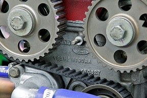
640px Ford Cosworth BDR 002
Wikipedia

To determine the size of a timing belt pulley, you’ll need to measure its outside diameter, pitch, and width. Let’s start with the pulley size measurement:

  1. Use a caliper or a ruler with millimeter markings to measure the outside diameter of the pulley. Make sure to measure across the widest point of the pulley, including any flanges or protrusions.

  2. Write down the measurement in millimeters. This value represents the outside diameter of the timing belt pulley.

How to Find the Outside Diameter of a Timing Pulley

The outside diameter of a timing pulley is an essential measurement when it comes to selecting the right pulley for your application. Here’s how you can find the outside diameter:

  1. Place the timing pulley on a flat surface, ensuring that it sits evenly.

  2. Use a caliper or a ruler to measure the distance from one edge of the pulley to the opposite edge, passing through the center. This measurement represents the outside diameter of the timing pulley.

  3. Note down the measurement in millimeters. This value will help you identify the correct pulley size for your timing belt system.

How to Measure the Pitch of a Timing Pulley

The pitch of a timing pulley refers to the distance between adjacent teeth. Measuring the pitch is crucial for ensuring proper synchronization between the pulley and the timing belt. Here’s how you can measure the pitch:

  1. Align the timing belt pulley so that one tooth is facing directly upwards.

  2. Use a timing belt pulley gauge or a ruler to measure the distance from the center of one tooth to the center of the adjacent tooth. This measurement represents the pitch of the timing pulley.

  3. Record the measurement in millimeters. The pitch value will help you identify the correct timing belt for your pulley.

How to Measure Belt Pulley Diameter

In addition to the outside diameter, it’s also important to measure the belt pulley diameter. This measurement helps determine the appropriate belt tension and ensures proper power transmission. Here’s how you can measure the belt pulley diameter:

  1. Place the timing belt pulley on a flat surface.

  2. Use a caliper or a ruler to measure the distance from one edge of the pulley’s groove to the opposite edge, passing through the center. This measurement represents the belt pulley diameter.

  3. Write down the measurement in millimeters. This value will assist you in selecting the correct belt size and tension for your timing belt system.

Remember, accurate measurements are crucial when it comes to selecting the right timing belt pulley for your application. By following these steps and using the appropriate measurement tools, you can ensure a proper fit and optimal performance of your timing belt system.

Now that you know how to measure a timing belt pulley, you can confidently proceed with your project and find the perfect pulley size for your needs.

Measuring the Timing Belt

The timing belt is a crucial component in an engine’s operation, ensuring the synchronization of the crankshaft and camshaft. To ensure optimal performance and prevent potential damage, it is important to measure the timing belt accurately. In this guide, we will explore different methods to measure a timing belt, its length, the distance between two pulleys, and the pitch.

How to Measure a Timing Belt

When measuring a timing belt, it is essential to consider various factors such as the belt’s width, pitch, and profile. Here are the steps to measure a timing belt:

  1. Measure the Belt Width: Use a caliper or ruler to measure the width of the timing belt. Ensure that the measurement is taken at the widest point of the belt.

  2. Determine the Belt Pitch: The pitch refers to the distance between the center of one tooth to the center of the next tooth on the belt. Measure the pitch by placing a ruler or timing belt pitch gauge against the teeth and measuring the distance.

  3. Identify the Belt Profile: Timing belts come in different profiles, such as HTD, GT, or T. To identify the profile, measure the distance between the highest point of the tooth to the bottom of the belt.

How to Measure a Timing Belt Length

Measuring the length of a timing belt is crucial for proper installation and tensioning. Here’s how you can measure the length of a timing belt:

  1. Wrap the Belt Around the Pulleys: Install the timing belt around the pulleys as you would during normal operation.

  2. Measure the Belt Length: Use a flexible measuring tape or string to measure the length of the timing belt. Start from the center of one pulley, follow the belt’s path, and measure until you reach the center of the same pulley.

  3. Consider Belt Tension: It’s important to note that the tension applied to the belt can affect its length. Ensure that the belt is properly tensioned before taking the measurement.

How to Measure the Timing Belt Between Two Pulleys

Measuring the distance between two pulleys is necessary to determine the appropriate length of the timing belt required. Follow these steps to measure the timing belt between two pulleys:

  1. Identify the Pulley Grooves: Count the number of grooves on each pulley. This information is crucial for calculating the correct belt length.

  2. Measure the Center-to-Center Distance: Use a measuring tape or ruler to measure the distance between the center of one pulley to the center of the other pulley. This measurement will help determine the required belt length.

  3. Calculate the Belt Length: Use the formula: Belt Length = (2 × Center-to-Center Distance) + (π × (Pulley Diameter 1 + Pulley Diameter 2)) + ((Pulley Grooves 1 – Pulley Grooves 2) × Pitch).

How to Measure Pitch on a Timing Belt

The pitch of a timing belt refers to the distance between the center of one tooth to the center of the next tooth. To measure the pitch accurately, follow these steps:

  1. Use a Timing Belt Pitch Gauge: A timing belt pitch gauge is a specialized tool designed to measure the pitch accurately. Place the gauge against the teeth of the timing belt and read the measurement.

  2. Measure Manually: If a pitch gauge is not available, you can measure the pitch manually using a ruler or caliper. Measure the distance between the center of one tooth to the center of the next tooth.

By following these measurement techniques, you can ensure the accurate sizing and installation of your timing belt. Remember to consult the manufacturer’s specifications and guidelines for precise measurements.

Calculating Belt and Pulley Parameters

Calculating belt and pulley parameters is an essential step in designing and maintaining efficient mechanical systems. By accurately determining the dimensions and specifications of timing belts and pulleys, you can ensure optimal performance and longevity of your machinery. In this article, we will explore the key formulas and methods used to calculate these parameters.

Timing Belt Calculation Formula

To calculate the dimensions of a timing belt, you need to consider several factors such as the pitch, width, and profile of the belt. The pitch refers to the distance between the teeth on the belt, while the width determines the contact area between the belt and the pulley. The profile of the belt corresponds to the shape of the teeth, which varies depending on the specific application.

One commonly used formula for timing belt calculation is:

Belt Length = (2 * Center Distance) + (π * (Pulley Diameter1 + Pulley Diameter2)) + ((Pulley Diameter2 - Pulley Diameter1)^2) / (4 * Center Distance)

Here, the center distance refers to the distance between the shafts of the two pulleys, and Pulley Diameter1 and Pulley Diameter2 represent the diameters of the two pulleys respectively.

How to Calculate Pulley Belt Length

Calculating the length of a pulley belt is crucial for ensuring proper tension and alignment. The length of the belt determines the distance it will travel around the pulleys, and it should be chosen carefully to avoid slippage or excessive tension.

To calculate the pulley belt length, you can use the following formula:

Belt Length = 2 * (Center Distance + √((Pulley Diameter1/2)^2 + (Pulley Diameter2/2)^2))

In this formula, the center distance represents the distance between the shafts of the two pulleys, and Pulley Diameter1 and Pulley Diameter2 correspond to the diameters of the pulleys.

How to Calculate Timing Pulley Belt Length

When it comes to timing pulleys, the calculation of the belt length is slightly different. Timing pulleys have grooves that match the teeth on the timing belt, ensuring precise synchronization between the pulleys.

To calculate the timing pulley belt length, you can use the following formula:

Belt Length = (2 * Center Distance) + (π * (Pitch Diameter1 + Pitch Diameter2)) + ((Pitch Diameter2 - Pitch Diameter1)^2) / (4 * Center Distance)

Here, the center distance refers to the distance between the shafts of the two pulleys, and Pitch Diameter1 and Pitch Diameter2 represent the pitch diameters of the pulleys.

By using these formulas and understanding the key parameters involved, you can accurately calculate the dimensions and specifications of timing belts and pulleys for your specific application. It is important to note that there are various tools available, such as pulley groove gauges and pulley measurement tools, that can assist in the measurement process and ensure accurate results.

Remember to always consider factors like belt tension measurement and timing belt inspection to maintain optimal performance and safety. With proper calculation and attention to detail, you can ensure the smooth operation of your machinery and avoid costly downtime.

Checking and Testing Timing Components

When it comes to maintaining the timing components in your vehicle’s engine, it is crucial to regularly check and test them to ensure optimal performance and prevent any potential issues. In this guide, we will focus on three key components: the timing belt tensioner, timing belt pulley, and timing chain tensioner. By understanding how to check and test these components, you can identify any problems early on and take the necessary steps to address them.

How to Check Timing Belt Tensioner

The timing belt tensioner plays a vital role in maintaining the correct tension of the timing belt. To check the timing belt tensioner, follow these steps:

  1. Start by visually inspecting the timing belt tensioner for any signs of wear, such as cracks or fraying. Ensure that the tensioner is securely mounted and that there are no loose or damaged components.

  2. Next, measure the timing belt pulley dimensions, including the pulley diameter, width, and groove. This can be done using pulley measurement tools or a timing belt pulley gauge. Refer to the manufacturer’s specifications for the correct measurements.

  3. Check the timing belt tension by applying pressure to the belt midway between two pulleys. The belt should have a slight amount of give, but it should not be too loose or too tight. If the tension is not within the recommended range, the timing belt tensioner may need to be adjusted or replaced.

How to Test Timing Belt Tensioner

Testing the timing belt tensioner is essential to ensure its proper functioning. Here’s how you can test the timing belt tensioner:

  1. Start by rotating the engine to the timing mark for the top dead center (TDC) position. This will allow you to access the timing belt tensioner easily.

  2. Apply a moderate amount of force to the timing belt at a point midway between two pulleys. Observe the deflection of the belt. It should deflect slightly, indicating that the tensioner is functioning correctly.

  3. If the belt deflects too much or does not deflect at all, it may be a sign of a faulty timing belt tensioner. In such cases, it is recommended to replace the tensioner to prevent any potential timing belt failure.

How to Test a Timing Chain Tensioner

For vehicles equipped with a timing chain, testing the timing chain tensioner is crucial for proper engine operation. Here’s how you can test the timing chain tensioner:

  1. Start by visually inspecting the timing chain tensioner for any signs of wear or damage. Ensure that it is securely mounted and that there are no loose or broken components.

  2. Check the timing chain tension by applying pressure to the chain midway between two sprockets. The chain should have a slight amount of give, but it should not be too loose or too tight. If the tension is not within the recommended range, the timing chain tensioner may need to be adjusted or replaced.

  3. Additionally, inspect the timing chain for any signs of excessive wear, such as stretched links or damaged teeth. If any issues are detected, it is advisable to replace the timing chain and tensioner as a set to ensure proper operation.

By regularly checking and testing the timing components in your vehicle’s engine, you can maintain their optimal performance and prevent any potential issues. Remember to refer to the manufacturer’s specifications and guidelines for accurate measurements and procedures.

Frequently Asked Questions

Q1: What are timing belt pulley specifications?

A: Timing belt pulley specifications refer to the detailed parameters of a timing belt pulley, including its diameter, pitch (the distance between the centers of two adjacent teeth), width, and number of teeth. These specifications are crucial for ensuring the proper functioning of the pulley system.

Q2: How do I measure a timing belt?

A: To measure a timing belt, you need to determine its length, width, and pitch. The length can be measured by laying the belt out flat and measuring it from end to end. The width is measured across the top of the belt. The pitch is measured as the distance from the center of one tooth to the center of the next.

Q3: How can I test a timing chain tensioner?

A: To test a timing chain tensioner, you can manually apply pressure to it and observe if it maintains its position. If it fails to hold its position or is excessively loose, it may be faulty. For specific models like the Audi A4, it’s recommended to refer to the vehicle’s service manual for detailed procedures.

Q4: How do I test a drive belt tensioner?

A: To test a drive belt tensioner, you can use a belt tension gauge or apply manual pressure to see if the tensioner maintains its position. If it moves too easily or doesn’t return to its original position, it may need to be replaced.

Q5: How do I calculate pulley belt length?

A: To calculate pulley belt length, you can use the formula: Belt Length = 2(Center Distance) + 1.57(Pulley Diameter) + (Pulley Diameter Difference / 2). This formula assumes that the belt is running on the outermost part of the pulleys.

Q6: How do I measure a timing belt pulley?

A: To measure a timing belt pulley, you need to determine its diameter, width, and number of teeth. The diameter can be measured using a caliper, the width can be measured at the base of the teeth, and the number of teeth can be counted manually.

Q7: How do I check a timing chain tensioner?

A: Checking a timing chain tensioner involves observing its ability to maintain tension. If it’s loose or doesn’t return to its original position after being moved, it may be faulty. For specific models, refer to the vehicle’s service manual for detailed procedures.

Q8: How do I calculate timing pulley belt length?

A: The formula to calculate timing pulley belt length is: Belt Length = 2(Center Distance) + 1.57(Pulley Diameter) + (Pulley Diameter Difference / 2). This formula assumes that the belt is running on the outermost part of the pulleys.

Q9: How do I measure pitch on a timing belt?

A: To measure the pitch on a timing belt, measure the distance from the center of one tooth to the center of the next tooth. This can be done using a caliper or other precise measuring tool.

Q10: How do I check a timing belt tensioner?

A: To check a timing belt tensioner, apply pressure to it manually. If it doesn’t maintain its position or is excessively loose, it may need to be replaced. A belt tension gauge can also be used for a more precise measurement.

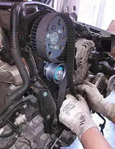
Timing Pulley:What Is, Types,Material,Interesting Guide

Replacing a timing belt

The pulley is a prevalent part of many types of machinery around us.

The timing pulley can adjust with misalignment and operate with desired timing.

This pulley is designed in such a way that it can prevent misalignment in the belt and pulley. The construction of the pulley is carried out with teeth and pockets on the periphery of the pulley hub.

The power is transferred smoothly with the mating of teeth and pockets with the belt. The teeth and pockets on this pulley differentiate it compares to others.

Types of timing pulley

The types of pulleys are differentiated by tooth profile, type of material, Dimensions, and applications.

For example, anti-backlash pulley, trapezoidal pulley, metal pulley, etc.

The pulley can be made with a variety of materials according to requirements.

The commonly used pulley is made with steel and aluminum. The pulley of other applications can be made from plastics.

Aluminum and nylon are the materials best suited for the manufacture of the timing belt pulley. This pulley required some particular type of feature to maintain a timing that can be fulfilled with these materials.

Timing pulley
Timing Belt and pulley Credit Wikipedia

What is timing pulley

The specialized pulleys are designed according to the requirement in applications.

The timing pulley contains the teeth and pockets on the periphery of the pulley hub.

This pulley transmits power by frictional force caused between the pulley and the belt surfaces. Though teeth and pockets are helpful to overcome misalignment and maintain timing, they are not used to transmit power.

The teeth on the timing pulley are engaged with the holes provided on the timing belt. The pockets on the timing pulley are mating with the lugs provided on the timing belt.

What is a timing pulley flange

The flanges are the supporting part of the pulley, as discussed below,

The function of flanges is not to allow the belt to escape from the pulley surface. It will help to maintain the lateral of the timing belt.

The flanges are mandatory on the pulley to keep the belt running on the pulley. The belt will jump out from the pulley if we do not provide proper flanges.

The flanges are made up of steel rings of various sizes. The size of the flange depends on the size of the pulley.

The flanges can be mounted on the pulley by pressing and fastening. The minor overlap is provided on the pulley to mount the flange on it.

What is the function of timing belt pulley

One can clearly define the function of the timing belt pulley with its name.

The precise homogeneous rotation between two shafts. It eliminates the slippage of the belt on the pulley.

There are no pockets or teeth over the traditional pulley. The timing belt pulley consists of teeth and pockets which not allow the belt to slip or misalign over a pulley. This pulley keeps the belt attached to the pulley surface.

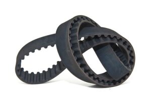
1024px 2001 honda accord timing belt terabass
Timing Belt Credit Wikipedia

How does the timing belt pulley work

The working principle of the timing belt pulley is similar to a traditional pulley.

This pulley is run with friction force caused between the pulley surface and belt.

The importance of teeth and pocket is to keep the belt attached to the pulley surface. They are helpful to assist timing and reduce misalignment. The teeth and the pocket are not used to drive the pulley.              

How to design timing belt pulley

The design of the timing belt pulley can be done with a few steps.

  • Find the maximum torque for your drive.
  • Find the largest pulley dimensions and drive ratio
  • Selection of the desired tooth profile and calculate the number of the teeth required
  • Determine the teeth in mesh (TIM). Determine design torque by dividing the maximum torque with TIM
  • Find the center distance of drive and determine the belt pitch length
  • Calculate the number of teeth on the belt by the ratio of the belt pith length and the tooth pitch
  • Determine the effective tension by utilizing data of the pitch radius and the design torque
  • Calculate the required break strength by the ratio of the effective tension to strength factor
  • Selection of pulley dimension and the belt dimension based on the design torque

How to remove timing belt pulley

This pulley is required a few steps to remove from the system

The middle tensioner bolt is loosened first by pushing the spring downward. The belt is now free.

How to measure a timing belt pulley

The dimension for the timing belt pulley can be determined as below

The pulley outside diameter and pitch circle diameter charts are used to determine the dimension of the pulley.

These charts are also helpful to find the interference for system design. The pitch circle diameter is the primary variable for designing the timing belt pulley.

How do you pick a timing belt and pulley

The selection of the pulley can be done based on some factors

The material, size, and environment are three essential factors  for the selection of the pulley.

The environment factor consists of temperature variation, oil and grease contact, and chemicals and gases.

The sizing of a belt can be done by finding the designed dimensions of the pulley and belt according to applications.

The material of the belt and pulley is selected according to environmental conditions and design.

Wing Pulley:What Is, Types,Material,Interesting Guide

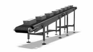
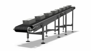
Inclined belt conveyor 300x169 1

The wing pulley is main component of the conveyor belt material handling.

It is known as self cleaning pulley. It is installed at tail of system to provide non continuous contact of particular wings.

The types of wing pulleys are differentiated by component thickness and applications.

  • Heavy-duty pulley
  • Mine duty pulley
  • Spiral wing pulley
  • EZ mount wing pulley
  • Beater bar wing pulley
  • SSP- Static shaft pulley
  • Quarry duty pulley
  • Grain herringbone pulley

There is a wide range of applications of the wing pulley. The classification s given based on its applications like mine, quarry, etc. The pulley is a primary component of the conveyor. The conveyor is widely used in the material handling system. The bulk material can be transferred with the conveyor easily.

Wing pulley
Belt conveyor with wing pulley Credit Wikimedia

The use of a this pulley can increase the life of the belt conveyor—the excessive build of the material on the belt in the regular drum pulley.

These phenomena cause damage to the belt conveyor and affect its performance. The wing pulleys are generally mounted on the tail side of the conveyor belt. The primary purpose of this system is to increase the belt life.

The location of this pulley is at the tail side of the conveyor belt. This pulley is also known as the self-cleaning pulley. The wing-type construction of the pulley lets the material distributed on the wings. There are fewer chances of material build up, so the flow of material is continuous.

Applications of wing pulley

The wing pulley can be used in a variety of material handling industries.

  • Coal
  • Grain
  • Agriculture material movement
  • Sand and flour handing
  • Tobacco manufacturing industries
  • Mineral handling system
  • Metal handling

The use of a wing can increase the performance of the belt conveyor with smooth running.

What is a wing pulley

This type of pulley is the mainly used at tail side of the conveyor belt.

It is called as a self-cleaning pulley due to its features. It is providing non-continuous contact of particular wings.

This construction design helps to make loose material collected far from the contact area. If we have a requirement of continuous contact, we should use a spiral pulley to complete fill contact. This pulley’s dimensions can be differentiated by using the thickness of the component and the rain force agent.

If the component thickness is more, the heavier wing pulley is needed in the conveyor. The rain force ring and the gussets are used between wing and member to sustain the heavier load. The pulley capacity depends on the diameter of the pulley.

Spiral wing pulley

The spiral pulley is functional when continuous surface contact is desired.

It is constructed by the pair of bars that are helically wound with the convolution of the individual.

The double cone design is constructed by attaching the gussets with every wing. The self-cleaning action is being done with the rotary motion of the spiral pulley. The different material is thrown toward the side of the conveyor belt.

The spiral pulley is helpful to reduce belt misalignment. There are fewer chances f the material being stuck between the belt and pulley due to many wings in the pulley.

Suppose steel bars are wound on the drum pulley, which meets at a center. The drum pulley is turned into a spiral pulley—the spiral pulley, also known as a pulley which provides continuous contact with the belt. The spiral flutes are found at both ends of the pulley.

Wing pulley dimensions

The dimensions of the this pulley depend on the size of the system

The main three dimensions of the pulley are pulley diameter, shaft diameter, and face width.

These dimensions can be calculated by the design of the pulley with known values of parameters. The size of the pulley depends on the size of the conveyor and its applications.

Mine duty wing pulley

There are some pulleys designed for the heavier applications like mine

The construction is heavier that reducing the chances of excessive material growth. The self-clean action is more effective in reducing mental fatigue.

 This kind of pulley is best suited for rough applications where the conditions are abrasive.

The mine duty or heavy-duty is designed for heavy loading applications. The pulley faces bulk handing with more material removal. A variety of different hub styles and gussets are available. We can choose the proper combination for desired applications.

Wing pulley lagging

There are some lagging provided on the pulley used in conveyor material handling.

It is a material layer provided over a pulley to protect the pulley, maintain friction between the belt and pulley and let the water take off from a pulley

The lagging material is designed to obtain maximum traction force in both directions. There are some more benefits of the pulley lagging discussed as below,

  • Reduction in downtime
  • Maintenance cost reduction
  • It is easy to adjust with flat and crown pulley
  • Decrease in wear between belt and pulley
  • Spillage prevention
  • Replacement can be possible without detaching the pulley

Wing pulley design

Various parameter calculations can design the wing pulley.

The pulley can be designed by calculating pulley diameter, shaft diameter, and face width.

The dimension of the wing pulley can be obtained by knowing the following parameters of the pulley :

  • Width of the belt
  • Centre of bearings
  • Tension on the tight side of the belt
  • Tension on the slack side of the belt
  • Arc of contact between belt.
  • If the width of the belt is less than 42 Inches,
  • the face width of pulley = Width of the belt + 2
  • If the width of the belt is more than 42 inches,
  • the face width of pulley = Width of the belt + 3

Wing pulley VS snub pulley

The applications of both pulleys are different, as discussed below,

The wing pulley is a self-cleaning pulley and located at the head and tail of the conveyor. The snub pulley is situated near to drive at return.

The function of the wing pulley is to drive the conveyor belt, whereas the role of the snub pulley is to raise the angle of contact on the drive pulley.

The dimensions of the wing pulley are more significant than the dimensions of the snub pulley.

Hydrocyclone Separator:Critical FAQs and Complete Insights

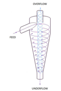
322px SiccaDania hydrocyclone 202x300 1

Hydroclone separator is valuable equipment for mining industries.

It is used to separate, de-sliming, dewater, and divide different phases from the feed. The benefit of the hydrocyclone separator is to separate different size materials.

There are many applications of the hydrocyclone separators in different other industries like food processing, wastewater treatment plant, civil construction, and manufacturing. There are some applications in which the water from the solid is dewatered to obtain the helpful product.

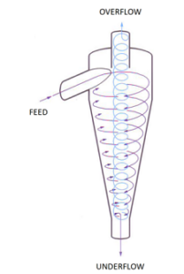
In most of the hydrocyclone, two outlets are provided. The coarse material is taken out from the apex. The fine material is taken out from the vortex finder.

What is hydrocyclone separator

It is valuable equipment for many industries and plants, including the separation process.

It works with cyclonic material movement that separates the product of different phases. This separation can be possible due to gravity.

Hydrocyclone separator
Hydrocyclone Separator Credit Wikipedia

The hydrocyclone separator comprises the cylindrical shape feeder with the tangential flow, vortex shape of overflow, and conical shape. There is no moving mechanism or part in hydrocyclone cyclone.

The primary function of the vortex finder is to differentiate fine material and coarse material with spiral shape motion.

What is the function of hydrocyclone

This device is highly used in mining and mineral processing plants.

It is a separation device that works on the gravity principle to separate different phases or weight particles. It can be possible to separate identical size particles with different weights.

This separator can separate particles based on weight and specific gravity. It is also possible to separate particles having the same specific gravity with different size

Hydrocyclone separator design

The hydroclone separator can be designed based on some parameters

  • The shape of the solid particle
  • Difference between the specific weight of different phases
  • The requirement of the feed speed
  • The medium’s density
  • The pressure at overflow and apex
  • Type of phases to be separated, e.g., oil, water, sand, gold, mud, etc.
  • Size of the applications
  • Chemical properties of the feed product

The design of the separator depends on many parameters, even more than above. The design can be done based on the application of product and size.

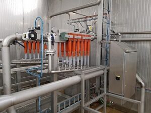
640px Starch recovery unit
Hydrocyclone in potato cutting food industry Credit wikipedia

The volume of the feed product should not exceed the escaping capacity of the outlet.

Hydrocyclone separator working principle

the working of the hydroclone separator is based on the motion provided by the equipment.

The centrifugal action inside the separator pushes the heavy phases particles outward direction. The apex of shape concentrates the collection of solid.

The shape of the device is such that decreasing continuously to increase the speed. The overflow outlet is used to take out the fluid with spiral movement in the vortex finder. The conical vortex is generated in the hydrocyclone separator.

How to size a hydrocyclone separator

The hydrocyclone separator can be designed on the size of applications.

The separator’s size depends on the stream flow rate, application type, plant size, etc.

The size of the separator can be calculated with the design. The design of the separator depends on some parameters discussed on the above topic (Click here).

The size of the apex is dependent on how much feed product we are supplying. It maintains the required force for centrifugation.

There are three main parameters for sizing the hydrocyclone: the sizing of apex, vortex finder, and the volume of the feed product.

Hydrocyclone sand separator

there are different separators classified based on the material to be separated.

The centrifugal action pushes sand particles outward that are collected in the sediment tank.

The sand separator works on the same principle of the centrifugation action. This action throws the heavier sand in an outward direction. This sand thrown in outward will collect at the bottom sediment tank. The movement of the sand particle is spiral from top to bottom. The lighter phase of liquid is taken out through the top of the separator with an upward motion.

It is helpful in irrigation water when a pile of sand is in water. The applications of the sand separators are deep well pumping, drip irrigation, pre-filtering for lab and industry, and micro-sprinklers.

Hydrocyclone oil separator

this separator is used to separate oil from the wastewater in oil industries.

The higher centrifugation action is required to separate oil due to its higher viscosity. The centrifugal force is the order of 1000 times more than gravity

The construction of this separator is the same as a conical chamber. There are two outlets in this conical separator. The spinning speed of the wastewater is very high to achieve high centrifuge action.

Hydrocyclone water separator

This separator is different from than oil separator in working.

The feed product enters with the tangential flow and achieves high vortex velocity. The bigger oil droplet is collected in the tapered part and tiny in the tail part.

The oil is separated in the small-diameter portion, and the bottom stream outlet separates the clean water. This type of separator is useful for irrigation and industries where water quality is not good.

Hydrocyclone gas separator

This type of separator separates two phases like gas-solid, gas-liquid, etc.

The gas with suspended particles is fed tangentially, and when it achieves the circular spiral motion. The particles with higher weight move outward to get separated.

The spiral motion of the gas is called spiral vortex motion. The decreasing diameter of the conical shape increases the velocity of the gas. The inner vortex flow of the gas moves upward, where it is collected as clean gas.

Turbine Efficiency:Complete Insights and FAQs

turbine efficiency 0

The efficiency of any device is a measure of its performance

The turbine efficiency is expressed as the ratio of useful work energy output to the input energy.

There are mainly two types of a steam turbines. One is an impulse turbine, and another is a reaction turbine. The efficiency of both turbines is different, and it depends upon its action of work.

There are many factors on which the turbine efficiency depends. It can be blade angle, guide vanes angle at the inlet to the turbine, velocity of steam, etc.

turbine efficiency formula

We can know and compare the performance of turbine with turbine efficiency

em%3E%7B3%7D h %7B4%7D%7D%7Bh %7B3%7D h %7B4s%7D%7D%7D%7D

Here,

h3 – enthalpy on point 3

h4 – the enthalpy point 4 (actual turbine)

h4s – the enthalpy point 4s (isentropic turbine)

The isentropic efficiency of the turbine can give us an ideal performance of the turbine. The heat rejected to the surrounding is to be assumed as zero. The isentropic efficiency can be calculated by the ratio of actual work to ideal work.

The ideal turbine is a device that works with 100 % efficiency. It means that all the input energy is converted into useful work. This type of turbine is impossible in the real world. There are always some losses present in the turbine in the form of heat and friction.

turbine efficiency
T – S Diagram of Rankine Cycle credit Wikipedia

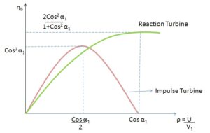
turbine efficiency curve

the turbine efficiency curve for impulse and reaction turbine is shown below

turbine efficiency
Turbine efficiency curve for impulse and reaction turbine credit Wikipedia

What is stage efficiency of a turbine

The stage efficiency or gross efficiency of the turbine is related to the stages of blades.

The stage efficiency is the ratio work supplied on the blade by per kg of steam to the energy given per stage (per kg of steam)

Stage efficiency can also be expressed as the multiplication of nozzle efficiency and blade efficiency.

In an impulse turbine, there are stages of blades and nozzle set. The stage efficiency is the providing performance of stage by work done in the stages and enthalpy dropping in nozzles.

gif

how to improve turbine efficiency

The turbine efficiency can be improved by some factors discussed below

It can be enhanced by the superior blade design, Coatings of exhaust blade and geometry

Why turbine has more efficiency than pump

The pump and turbine efficiency can be compared based on fluid handling

The pressure losses in the pumps are higher than in the turbine. This loss can be reduced by making the boundary layer thin in the turbine.

The working fluid in the turbine is expanding from the inlet. At the inlet, the static pressure and the velocity rise continuously. The rising in the kinetic energy of the fluid leads to a decrease in losses. The thin boundary layer can decrease the losses of power.

In the pump, the boundary layer thickness of fluid is more due to deceleration to raise static pressure. This increase in thickness leads to an increase in the losses in the pump.

average turbine efficiency

The average efficiency of the turbine varies between some range depending on size and stage.

The average efficiency of a single-stage turbine is 40 % whereas, the efficiency for the multi-stage turbine is 65 – 90%.

The efficiency in the multistage turbine is high due to the moderate to high pressure ratio. The steam will get expanding through various stages, which is beneficial to efficiency.

What is the ideal efficiency range for practical turbines

The ideal efficiency range of a practical turbine is dependent on various losses.

The overall plant thermal efficiency for the steam turbine is 42- 45%.

The power plant running on the superheated boiler is working with fossil fuels like coal. There are many heat losses present in a practical turbine. Due to thermal losses, the efficiency of the practical turbine is low.

turbine vs piston efficiency

The turbine and piston engine can be compared for aircraft

The piston engine is more efficient compared to the turbine due to less specific fuel consumption.

The turbine is light in weight compared to piston engines. The weight of piston engines is more due to bore, turbocharger, etc. To reduce the unbalancing in an airplane, a long nose is provided.

What is the maximum efficiency of a generator

The generator is a device that provides electrical energy at the expense of mechanical energy.

If the losses are proportional to the square of load current, then the generator’s efficiency is maximum.

The generator efficiency can be stated as the ratio of output electrical power to input mechanical power.

The efficiency of the dc generator can be maximum if the variable and constant losses are the same. The variable losses are armature losses, and the constant losses are field circuit losses and rotational losses.

How To Reset Camshaft Position Sensor: 7 Important Facts

The camshaft position sensor can be reset with the precautions of other car equipment.

The performance of the inductive sensor can be checked with a voltmeter and ohmmeter. Induction phase detector resistance in between 200 to 900 Ω

The measured resistance will be verified by comparing it with standard car data.

Switch off the ignition switch before measurement.

Take out the induction phase sensor (camshaft position sensor)

Connect two terminals of the voltmeter with the sensor.

Start the engine and let it run on idle

Your RMS value should be more than 0.75 V

What is a camshaft position sensor?

The camshaft position sensor provides valuable data to the engine control system.

It sends positional data of camshaft and crankshaft to the ECU. This position data helps estimate ignition points and injection points.

camshaft position sensor
Crank shaft /Camshaft position sensor Credit Wikipedia

The camshaft position sensor data is used in the engine control system to carry out further steps of combustion. For any engine, the ignition point is essential for better performance. This data can be calculated by the positioning of the camshaft.

Camshaft sensor principle: Functional principle

There are two sensors used to define the position of the crankshaft drive in the engine.

This sensor works on the hall principle. The sensor records the ring gear and changes the voltage reading accordingly.

The change in voltage is recorded and sent to the transmitter device. The voltage signal is studied in a transmitter device, and the required data is produced from it. Combining the signal from the camshaft sensor and crankshaft signal is helpful to get to know the position of the first cylinder in the top dead center.

Where is the location of the Camshaft Position Sensor?

This sensor is helpful for an engine control system to generate required data.

It is utilized to get position and monitor the rotation of the camshaft. The location of the sensor is nearby the cylinder head. This location is convenient to read timing rotor coupled with camshaft.

The electronic control unit (ECU) decodes the signal as the angle of the camshaft. It will calculate the recognition of the cylinder based on the signal given by this sensor.

In modern engine technology of auto start and stop, This sensor scans the cylinder on expansion stroke. It is helpful to supply fuel and advance spark with your acceleration act. A faulty camshaft sensor warns you about its condition before it is useless.

Is it safe to drive with a bad camshaft sensor?

This sensor is helpful to improve the engine performance with signals.

You will not face any driving problems. The engine performance and fuel economy can be affected by lousy camshaft sensors.

This sensor is necessary to improve the performance and fuel economy of any engine. An engine electronic control unit controls the fuel supply and other systems. This ECU collects signals from various sensors, which is ultimately used for further calculation of another system.

The lousy camshaft sensor affects the engine ignition system. It will not be helpful to calculate information for spark advance and fuel supply at the right time. It will always be recommended that you keep your camshaft sensor up to date for the proper functioning of your vehicle.

Can I replace my own camshaft position sensor?

The camshaft position sensor is rarely found at fault except for some physical damages.

Yes, You can replace the camshaft positioning sensor with a basic repair manual (DIY) for your vehicle. You should know its look and location in the car.

The camshaft sensor is working more for an extended period without losing its performance. If you want to replace it, you should know how it looks like and where its location is. Though the faulty replacement of the camshaft position sensor is not lead to stopping your vehicle from working. If you have made any mistake in replacement, you have to visit a mechanic for further guidance.

What causes a camshaft sensor to go bad?

Several aspects can affect the performance of camshaft position sensor

  • Damage due to water
  • Wear or tear
  • Damage due to corrosion of metallic parts
  • Damage due to engine oil leakage
  • Overheating or melting
  • Damage due to short circuit
  • Damage due to fire or spark
  • Other physical damages

There are many different possible reasons to affect the performance of the camshaft positioning sensor. The camshaft positioning sensor can work properly if you maintain your car regularly.

Which is a common problem for camshaft position sensor circuits?

The camshaft position sensor delivers a positional signal to the Electronic control unit circuit.

The sensor circuits can fail mostly with accidents or oil leakage from the engine. It will stop or reduce the signal sending capacity of the sensor.

The engine oil can cause leakage and affect the sensor if improper tightening or loss of engine components. The leakage oil stops the signal carrying capacity of wiring and circuits.

Can you clean a camshaft position sensor?

Periodic maintenance is required for any equipment associated with the car.

It is easily clean camshaft position sensor  with some care. Read more information below for proper steps for cleaning.

The first step is disconnecting the battery with an engine so that all electrical and electronics circuits remain off. Find the place of the camshaft position sensor in your vehicle.  

Disconnect the sensor’s three cables and remember it at the time of connection. Now clean the sensor with a cleaning solution and dry it before connecting.

Connect the sensor with its original three wire location. Connect the battery again and let the system run. You have cleaned the camshaft position sensor. Repeat this procedure after some period of time.

Saturated Liquid: 7 Important Facts You Should Know

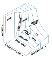
PVT 3D diagram

Saturated Liquid Example:Comparative Analysis and FAQs

There are many liquid at some temperature and pressure considered as saturated liquid

  • Water – saturation condition of water is 100 C temperatures with atmospheric pressure
  • Carbontetrachloride (R10) – Temperature 76.69 C
  • Ammonia – Temperature -33.33 C
  • Ethylene glycol – Temperature 197 C
  • Petrol – Temperature above 37.5 C
  • Acetone – Temperature 56.7 C
  • Methyl alcohol –Temperature 65 C
  • Ethyl alcohol – Temperature 77.8 C
  • Kerosine – Temperature above 151 C

The above are the example of saturation state of some liquids. The boiling point of any liquid indicates its saturation state with atmospheric pressure. In simple words the saturates liquid means the condition of liquid to get vaporize with small change in temperature. The existing temperature of the saturated liquid is called boiling point of that liquid.

What is a saturated liquid?

The saturated word is associated with phase changing phenomena.

The temperature and pressure of a liquid are maintained in such a way that by reducing pressure slightly with constant temperature, it will starts evaporating liquid

The liquid at saturated temperature and pressure is considered as saturated liquid in general term.

saturated liquid
Saturated dome credit wikipedia

Saturated liquid is well understood by calling it the liquid which just about to evaporate. At the normal temperature 20 C and normal pressure 1 bar the water remain at the liquid condition. If we keep pressure same and increase temperature around 100 C, The water possess the state of vaporization readily with minor change in temperature.

The values of the various thermodynamic properties of the saturated liquid can be obtained from the table. If you know the values of pressure and temperature, you can obtain values of specific volume, enthalpy, entropy etc.

How do you know if a liquid is saturated?

It is very necessary to get know the saturation state of any liquid for understanding its properties

We can say that saturated liquid is ready to vaporize in minor change in temperature or pressure. The temperature of substance will not increase while liquid is getting evaporated.

The temperature remains constant in phase change process. At the vaporization or evaporation process, The temperature is utilized for vaporization. During this vaporization process, if vapour under goes some loss in temperature, it will starts condensing. We can call it as a saturated vapour.

Is water a saturated liquid?

Any liquid in universe can be saturated liquid at some thermodynamic conditions

The water is saturated liquid if its pressure and temperature are 1 atmospheric and 100 0C. at this condition, the water will easily get vaporize with minor increase in temperature at constant pressure.

During this vaporization process, if vapour under goes some loss in temperature, it will starts condensing. It is considered as a saturated vapour. If we try to increase temperature further more, The vapour will get pressurize (converted into superheated vapour)

Is Water Vapor an Ideal Gas?

There is some temperature and pressure conditions for water vapor to be considered as ideal gas.

If the pressure of the water vapor is below 10 kilo Pascal  to be considered as ideal gas without focusing its temperature.

To satisfy above condition, the error should be nearby 0.1 %. There are unwanted earrors arising during higher pressure conditions. It may be nearby the saturated vapour line and critical point.

What is the difference between saturated liquid and saturated vapor?

The liquid and the vapor are different state of matter.

We can say that saturated liquid is near to evaporate with small increase in temperature with constant pressure.

During this vaporization process, If there is decrease in minor temperature of vapour, the condensation process will starts. We can call it as a saturated vapour.

The temperature of substance will not increase while liquid is getting evaporated. The temperature remains constant in phase change process. At the vaporization or evaporation process, the temperature is utilized for vaporization.

What is meant by a saturated liquid and vapor?

The liquid and vapor are two different state of matter with some conditions.

The saturated liquid means the phase of matter is liquid. The saturated vapour means the phase of matter is gaseous.

The word saturation attached with liquid and vapor because it indicates the condition. The condition of saturated liquid is to vaporize with minor raise in temperature. The condition of the saturated vapor is to get condensed with minor decrease in temperature. We can consider the pressure remains constant in both.

What is saturated solution?

The saturated solution is term used in the chemistry.

The solution can be said saturated if we add more substance in it; it will either precipitate at bottom or converted into gas.

The saturation solution is chemistry term. It is used to indicate the state of solution that addition of substance cannot dissolve the substance more. It will either settle down at the bottom of the glass vessel or converted into the gas.

Examples of saturated solution

There are many saturated solutions exist in our day to day life

  • Seawater
  • Water with soap in it
  • Milk with chocolate powder in it
  • Juice with powder
  • Syrup of pan cake
  • Solutions used for cleaning
  • Beverages with some sweet in it
  • Freshwater with some elements in it
  • Soil – It is saturated solution with element like nitrogen
  • Air including moisture in it

There are many solutions in chemistry as well in nature to be considered as saturated solutions. Above are the common examples but there are lots of examples available for saturated solutions.

Gas Turbine Cycle: 5 Important Facts You Should Know

regeraton1

There are two types of gas turbine open cycle and closed cycle. The thermodynamic cycle used in a gas turbine is the Brayton cycle

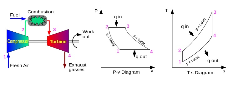
The air is used as a working fluid in the Brayton cycle. The compressor pressurizes the air and then lets it ignited by spraying fuel over it. The generated high temperature gas is further expanded in the gas turbine to net work output.

The Brayton cycle consists of four significant processes given in the table below,

Process 1-2Isentropic compression (In Compressor)
Process 2-3Constant pressure heat addition (In combustion chamber)
Process 3-4Isentropic expansion (In turbine)
Process 4-1Constant pressure heat rejection (exhaust)

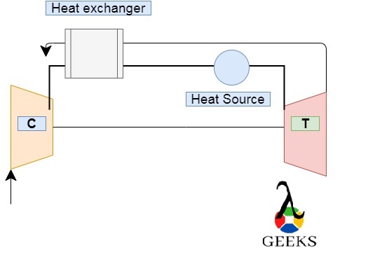
In the gas turbine cycle, the widely used cycle is a closed-cycle gas turbine. There are few methods employed to increase the performance of the cycle. The gas turbine power plant can give quick output power as compared to coal based thermal power plants.

Gas turbine cycle
Gas turbine cycle Credit Wikipedia

Components of gas turbine cycle

There are four main components of the gas turbine cycle. The additional components are used to increase performance

  • 1. Compressor
  • 2. Combustion chamber or combustor
  • 3. Turbine
  • 4. Condenser
  • 5. Regenerator heat exchanger
  • 6. Intercooler
  • 7. Reheater

The function of every component is predefined in gas turbine cycle. In an open cycle gas turbine, the atmospheric air is compressed by a compressor. The temperature of the air is raised enough to ignite fuel in the combustor. After combustion, the high temperature gas is supplied to the turbine. The turbine blade is getting rotated due to the expansion of this gas. The turbine shaft is rotated with constant output.

The closed-cycle gas turbine is working on the principle of the Brayton cycle (Joule’s cycle). In a gas turbine cycle, the type of compressor used is rotary to pressurize the air isentropically. This higher pressure air is supplied to Combustor. In combustor, the temperature of air is raised at constant pressure. There are two types of combustors available for gas turbine.

1) Radial or annular type 2) Can type

The heated air from the combustor is let expand in turbine for power generation. The electric generator is used with a turbine to transfer mechanical energy in the electrical energy.

The expansion process is carried out at constant entropy (isentropic). After expansion, the gas is getting cooled into the condenser. The condenser is one type of heat exchanger with water as a coolant.

The cooled gas is again reaching the compressor. This process will get repeated continuously for constant power generation.

Gas turbine cycle with regenerator

The regenerator is one of the proper methods to increase the efficiency of the gas turbine cycle.

The counter flow heat exchanger (regenerator) is utilized to exchange heat from exhaust gases of turbine to pressurized air leaving the compressor.

The thermal energy of the gas turbine cycle is increased due to the reuse of exhaust heat. We can say that regeneration decreases the fuel required (by reducing heat input). The regeneration method can increase the thermal efficiency of the gas turbine plant in the range of 35 to 40%. The regenerator causes minor pressure loss in the system. The power output slightly decreased due to pressure loss.

Though the cost and maintenance of the regeneration cycle are required, the overall benefit is more likely. Compared to fuel cost, the regeneration gas turbine cycle is highly beneficial.

Practical example of a closed cycle gas turbine

The closed-cycle gas turbine has the potential to supply quick and continuous power supply by utilizing the following heating sources.

  • Fossil fuel
  • Biomass energy
  • Solar energy (Concentrated solar energy)
  • Nuclear energy source
  • Waste heat recovery
  • Geothermal energy
  • Hybrid energy source
  • Renewable fuel

The gas turbine cycle can be clubbed with any above listed heating source. The other components like compressor, turbine, and condenser in the gas turbine cycle remain the same. The heating source can be varied from the above examples as per the requirement of power and energy. The widely used fuel for a gas turbine is natural gas or LPG (liquefied petroleum gas). These natural gases are well-known to be utilized because of their properties  of combustion and purity. The turbine-like 400 GE is operating on the fuel naphtha, crude oil, or heavy fuel.

The present technology also focuses on the reduction of carbon emissions. The hydrogen powered turbine has been developed to reduce pollutions. As we know, hydrogen has a vast potential for future energy. This turbine is flexible to be utilized in existing as well new power plants to reduce emissions.

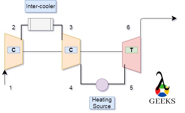
Intercooling and reheating in a gas turbine cycle

The Intercooling and the reheating is an additional arrangement to the gas turbine cycle.

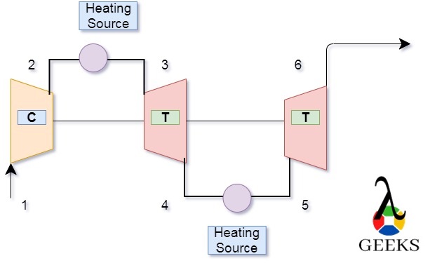
The air is cooled in between two stages of compression in inter cooling. This process can reduce the compression work and the output of the gas turbine cycle. In reheating, the hot flue gas from the turbine is again reheated to get expand in another turbine.

The reheating is superior to increase the turbine work. The reheating and intercooling are method for improving the specific power output and thermal efficiency of the gas turbine cycle.

Reheating
Reheating in Gas turbine
Coling
Intercooling in Gas turbine

FAQs

Why are intercoolers used in the compressors?

The intercooler is a valuable component in-between stages of compressors.

In various stages of the compressor, the high temperature of gas from the first stage can reduce the performance of the second stage of the compressor.

The intercooler is installed in between the two stages of the compressor. The hot air from the first stage is cooled in the intercooler and then supplied for second stage compression.

The high temperature occupies more volume of the compressor due to more intermolecular distance. The function of this device is to decrease this volume. The reduction in volume is more beneficial to rise in pressure.

During the intercooling, the water vapors are formed due to the cooling of air. It is required to separate that water vapors from the air. It is also a prime function of the intercooler to supply dry air to the second stage.

AFBC boiler: 17 Answers You Should Know

Somketube fbc 300x226 1

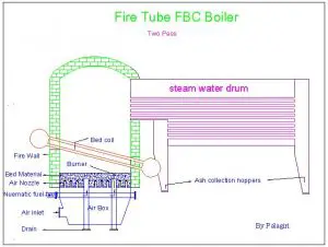
afbc boiler flow diagram | afbc boiler diagram

afbc boiler
Schematic diagram of FBC boiler credit Wikipedia

advantages of cfbc boiler over afbc boiler | difference between afbc and cfbc boiler

AFBC means atmospheric – fluidized – bed – combustion. The speciality in this boiler is to keep furnace pressure at atmospheric conditions. The burnt gases developed in the combustion chamber are passes through the cyclone and are discharged into the atmosphere.

CFBC means circulating – fluidized – bed – combustion. In this kind of boiler, the furnace gas is pressurized to recirculate in the chamber. This recirculation of gases captures the unburnt carbon. Thus, the thermal efficiency of a boiler is increasing because of gas recirculation.

The comparison of the AFBC and CFBC boiler can be made based on the following parameters and criteria.

The velocity of the gases

In AFBC, It is around the 1.2 – 3.7 m/s

In CFBC, It is around 3.7 – 9 m/s

Heat Transfer Surface

In AFBC, The heat extraction can be done from bed only

In CFBC, The heat transfer was carried out bed and other surfaces of combustion chamber. It is known as the convective zone. The heat transfer from water walls is possible.

Fuel size

Coal is a widely used fuel in both boilers, but the size of coal particles in CFBC is 2-3 mm more.

Supply of air in combustion chamber

In AFBC boiler , The range  is  3 to 5 PSI gauge

In CFBC boiler, The range  1.5 to 2 PSI gauge

From above comparison we can say that the Performance characteristics of the CFBC boiler are better than the AFBC. It is an advanced technology of circulating gases. It is developed to solve some difficulties that arise in the AFBC. Some of them are discussed as below,

  • 1. The utilization space in the CFBC boiler is adequate than AFBC.
  • 2. The combustion of fuel is efficient more in the CFBC boiler.
  • 3. SO2 and NOx can be controlled more in the CFBC boiler.
  • 4. The control of temperature is more in the CFBC boiler.
  • 5. It can work effectively even with the low calorific value of the fuel.
  • 6. the turndown ratio is higher
  • 7. Both over & under feed systems can be used

afbc boiler working principle | afbc boiler start-up procedure

  • Following are the steps to be followed to start the afbc boiler
  • The air nozzles are cleaned by entering the full Fd air into the combustion furnace. Open the air compartment door for 10 to 15 minutes to complete this task
  • Enter the bed material into the combustion furnace. The bed height is to be around 250 to 300 mm above the nozzles.
  • The material below the nozzle is to be a static fix. It is also considered in the bed height
  • Enter the fluidizing air through the complete bed to uniformly distribute the bed materials over the bed. The PA damper is kept close during this operation
  • Open the startup compartment when you feel the uniformity in bed material and bed height.
  • Now increase the flow of air to develop tiny bubbles all over the bed material. This stage is called the bubbling stage. Read the airflow rate and note it down at this stage.
  • In the next step, Increase the furthermore the flow of air to make the bed turbulent. It is helpful for proper mixing of the upper and lower layer of the bed material. This is called the mixing stage. Read the airflow reading at this stage.
  • Switch off the fan and airflow rate. Now boiler is ready to start
  • The drum is level is to be maintained at around 40 %
  • Initiate firing
  • Keep initializing for few minutes, start All three fans as per sequence (ID, FD and PA)

afbc boiler design | accepted range of afbc boilers

The construction and working of AFBC with an explanation of various parts involved,

Main systems in the AFBC

  • Fuel supply system
  • Air Distribution
  • Heat transfer in Bed and surface
  • Ash Control system

Generally, these four main systems are included in every FBC boiler.

1. Fuel Supply System

There are two types of fuel supply systems in FBC boilers. Under-bed pneumatic supply and over bed supply.

The absorbent is used for fuel supply—examples: dolomite, limestone etc.

In under bed pneumatic supply, the coal is crushed and pulverized in 1 to 6 mm in size. This coal is supplied from the inlet hopper to the combustion chamber with the pneumatic arrangement. This system is developed according to capacity.

2. Air distribution system

The air distributor is the main component of any FBC boiler. It is utilized to pass or distribute the fluidized air from the furnace bed. The air distributor is keeping the solid particle motion at a constant rate. The air distributor is made from a metallic plate. The pattern geometry is made with the perforation in it. The nozzles are installed with perforation in it. This perforation is not allowing the solid particles to go back into space.

There are some arrangements made to protect the distributor from the temperature of the bed.

i) Refractory material Lining brick

ii) Fix layer of the materials in bed

iii Cooling tubes

3. heat transfer in bed and other surfaces

a)  heat transfer in Bed

The bed is made with particular kinds of materials like crushed limestone, refractory, ash and sand. The size of material particles is around 1 mm. There are two types of bed widely used beds in the FBC boilers.

(1) Shallow bed

(2) Deep bed

(1) Shallow bed

The power consumption of the fan is low in the shallow bed. In addition, the resistance of the bed is less in shallow beds, so the pressure drop is also lower.

(2) Deep bed

The power consumption of the fan is high in the deep bed. The resistance of the bed is more in a deep bed. The gas velocity is raising because of  pressure drop.

b)  Heat Transfer on surface

In the FBC boiler, the heat transfer should be sufficient within the bed material and the bundle of the tube or coils. The heat transfer is more superior in the horizontal orientation of the heat exchanger in shallow bed air distribution. There are few  parameters on which the heat transfer is depending,

Temperature of bed

Solid fuel particle size

Design and the layout of heat exchanger

Structure of the air distributor

Velocity of gas

4. Ash Handling System

a) Bottom Ash drain

There are two types of ash present in the FBC boiler. One is the fly ash, and the other is the bottom ash. Generally, the sediment ash is nearby 30 to 40 %. This ash is taken out when exceed limit to control bed height.

b) Removal of fly ash

The fly ash of the FBC boiler is more than other boilers. The combustion efficiency can be increased by utilizing the fly ash in some units. It is happening because the speed of the particle is very high. The fly ash travels with the flue gases, which is taken out at various stages from the FBC unit. There are three stages for the removal of the fly ash. (1) Convection part of FBC (2) Before air preheater or economizer (3) dust collector

There are many types of dust collectors available in the FBC boilers. (1) Cyclone (2) electrostatic precipitator (3) bagfiler (4) Combination of dust collectors

afbc boiler bed height calculation | afbc boiler bed height

The height of bed is calculated with the following equation in boiler,

level  of bed = Pressure in wind box – Differential pressure in the bed nozzles

DP test in afbc boiler | dp test procedure for afbc boiler

  • The first step is to precheck the bed with the following steps:
  • Make bed properly clean
  • Complete the maintenance of air nozzle and bed
  • The FD fan should work with higher efficiency
  • Steps of Procedure for DP test:
  • Initially start the ID fan, Start FD fan with minimum speed
  • Keep Air preheater inline
  • Raise the speed of airflow (Increase from 25% – 100%)
  • Read and note the pressure in the wind box at every stage
  • For all other compartments, repeat the same procedure
  • The value of pressure in the wind box needs to be nearby with designed values
  • Interpretation of DP test
  • The nozzle, bed plates are in good condition if the value of wind box pressure is nearby the designed value
  • The nozzles may be blocked if the value of wind box pressure is exceeded the design value
  • The nozzles may be damaged or defected hole if the value of wind box pressure is less than the design value

bed material size for afbc boiler |  afbc boiler bed coil

In the AFBC boiler, there are many grades of solid fuel (coal) available. The size of the coal particle is varied from 1 -10 mm. The size of coal particle is chosen based on the type of coal, quality of coal etc. The atmospheric air is used for two purposes, fluidizing air and air for combustion. First, this air is provided with sufficient pressure over the bed. Second, this is preheated by an air preheater in the boiler.

The velocity of this fluidizing air can be in the range of 1.2 – 3.7 m/s in the AFBC boiler. The flow rate of air passes through the bed can be utilized to determine fuel reaction. The bed temperature can be maintained by installing the bed evaporator tube to construct a limestone or sand bed. The bed evaporator tube helps reject the heat from the bed to maintain the temperature of the bed.

The bed is made up of depth  0.9 m to 1.5 m. the pressure drop across the bed is expected around 1 Inch per inch of depth of the bed.

The generated flue gases from the FBC combustion chamber is passed through the superheater section, economizer and air preheater. After air preheaters, the flue gases are exhausted from the atmosphere.

The AFBC boiler is famous for its temperature range. The temperature range of the AFBC boiler is 800 °C to 950 ° C. If the temperature exceeds this range, the boiler’s performance is decreased.

afbc boiler air nozzle

Two types of nozzles are widely used in the AFBC boiler.

Fluidizing nozzle:

This type of nozzle is made up of the S S or alloy steel. It is fitted on the bedplate. The hole size is about 2 – 5 mm. The air of the FD fan is entering from the wind box to the combustion furnace.

Coal feed Nozzle:

This nozzle is used to enter coal with air into the combustion furnace. The total number of nozzle is taken according to the size and capacity of the boiler. It may be 4 -6 nozzles. It is also fitted on the bedplate.

afbc boiler bed material density

The material density of the bed is around 1100 kg/m3

afbc boiler efficiency | afbc boiler efficiency increase

The combustion efficiency is depending on the following parameters :

(1) Reaction properties of fuel

(2) Volatility of fuel

(3) Size of the fuel particle

Coals like sub-bituminous or lignite are highly efficient in burning. There is no fly ash recycling or under a bed; feeding requires if the coal quality is good. The combustion efficiency of the AFBC boiler is in order of 70 to 99 %. The combustion efficiency is decreased. The efficiency of the AFBC boiler can be achieved by system improvement. The coal-like anthracite burns with low efficiency in the AFBC boiler. It can burn with higher efficiency in the CFBC boiler with the applications of fly ash recycling and the under bed feeding.

afbc standard boiler parameters

The following are the standard parameters which the of the AFBC

  • Size of the coal particles
  • Specification and size of the bed material
  • Air pressure from the FD fan
  • Height of the bed
  • Temperature of furnace
  • The temperature of the bed

afbc boiler velocity of flue gas | flue gas velocity in afbc boiler

The velocity of this fluidizing air can be in the range of 1.2 – 3.7 m/s in AFBC boiler.

afbc boiler interview questions and answers

What steps will you follow if the temperature of the bed increases?

The following are the points to be considered if the temperature of the bed is raising,

  • Load reduction
  • Maintain the density of the coal
  • Increase the material of the bed

What are the probable facts for the decrement in bed temperature?

  • The following are the probable facts for the decrement in the bed temperature,
  • The quality of material used in bed is poor
  • Suddenly action of the boiler load reduction
  • Excessive air entered the furnace
  • Fuel contains moisture

What is the reason behind the use of lime in the AFBC?

The coal contains some moisture, which has to be removed before combustion for better combustion efficiency. The purpose using lime is to absorb and remove the moisture from the fuel.

Which one is superior CFBC or AFBC ? Explain why?

We can conclude that the Performance of the CFBC is more superior to the AFBC. It is an advanced technology of circulating gases. It is developed to solve some difficulties that arise in the AFBC. Some of them are discussed as below,

1. The utilization space in the CFBC boiler is adequate than AFBC.

2. The combustion of fuel is efficient more in the CFBC boiler.

3. SO2 and NOx can be controlled more in the CFBC boiler.

4. The control of temperature is more in the CFBC boiler.

5. It can work effectively even with the low calorific value of the fuel.

6. the turndown ratio is higher

7. Both over & under feed systems can be used

For more Articles related to Boiler Please click here

Babcock And Wilcox Boiler: 11 Facts You Should Know

800px Babcock and Wilcox boiler Heat Engines 1913 1 300x233 1

Content

Keynotes

Babcock and Wilcox boiler | what is Babcock and Wilcox boiler

  • Stationary
  • Water tube
  • Externally fired

Babcock and Wilcox boiler parts

  • Drum or shell
  • Superheater
  • Water tubes
  • Upper and lower header
  • Furnace
  • Baffles
  • Grates
  • Fire door
  • Anti priming pipe
  • Mud box
  • Man hole

Babcock and Wilcox boiler accessories & Mountings

  • Water level indicator (Indicate water level)
  • Steam Stop valve
  • Safety valve (To reduce pressure)
  • Superheater (Increase temperature)
  • Pressure gauge (Pressure measurement)

Why are the tubes of water tube boilers kept inclined?

The water tubes are joined with the water steam drum. The water tubes are installed inclined with the boiler to improve heat transfer and get other benefits. The water tubes is kept 15° angle of inclination. The tube diameter of the water tubes installed in this boiler is approx. 10 cm.

The tube inclination is increasing  the convection heat transfer in the tube.

Babcock and Wilcox boiler diagram | Babcock and Wilcox boiler easy diagram | Babcock and Wilcox boiler images | Babcock and Wilcox boiler schematic diagram

Babcock and Wilcox boiler
Babcock and Wilcox Boiler Credit Wikipedia
Babcock and wilcox schematic
Babcock and Wilcox Schematic
Image Credit Research gate Dr. Ravindran S., Shanmugam

Working of Babcock and Wilcox boiler

Lets’s learn the working of the Babcock and Wilcox boiler with details and stepwise.

  • The water is stored inside the drum. Then, the fluid initiates flowing from the steam –water drum to the incline water tubes (through the lower header).
  • The solid fuel burning in the furnace generates the hot flue gases passing over the water tubes. The water tube contains water in it which is get heated because of hot flue gases. Here, the baffles are very helpful to increase heat transfer. The hot gases pass through the zigzag motion due to baffles.
  • The water inside water tubes absorbs heat from hot flue gases and changes the phase from water to steam.
  • The produced steam inside the water tube will travel to the top and collected inside the topmost portion of the drum.
  • The function of an anti priming pipe is to reduce moisture content present in the steam. There are some holes inside the anti priming pipe, which is useful to lower the moisture. After separating moisture content, this pipe transfers the high pressure steam to the superheater for next steps.
  • The function of a superheater is to raise the temperature of the steam to make it suitable for power generation. Then, the super-heated steam is supplied to the steam stop valve pipe.
  • The steam from the superheater is either taken out or stored in the drum for another process. If the steam is taken out from the boiler, it is supplied to the turbine for power generation. The steam of boiler can be used for process heating purposes also.

Advantages of Babcock and Wilcox boiler | advantage of Babcock and Wilcox water tube boiler

The advantages of Babcock and Wilcox boiler are discussed in detail :

  • The efficiency of this boiler is more compared to others. The efficiency is expected around 60 to 80%
  • The generation of steam is higher in this boiler. It is approximately 20,000 to 40,000 kg of steam in one hour (Pressure range between 10 to 20 bar).
  • This boiler is easily maintainable compared to others.
  • It is easy to change the faulty tube in Babcock and Wilcox boiler.
  • The tube expansion and tube contraction cannot create problem in this boiler. The water drum and water tubes are loosely connected in the brick wall so that it is easy to expand and contract tubes during heat transfer.
  • The loss due to drought in Babcock and Wilcox boiler is very less.
  • The boiler inspection is convenient during boiler working.
  • It is easy to clean and repair every part of the Babcock and Wilcox boiler due to its better accessibility.
  • It is possible to obtain temperature and steam quickly in this boiler. Therefore, it is suitable to meet the quick demand for steam.
  • It can deliver highly dry steam even if the water supply is not proper compared to other boilers.
  • It requires less floor area per steam generation as compared with the fire tube boiler.

Disadvantages of Babcock and Wilcox boiler

There are some disadvantages of the Babcock and Wilcox boiler as discussed below in detail,

  • The water requires for the boiler should be very pure. Even a few impurities in the water can cause scale formation in water tubes. This scale formation results in a reduction in steam generation due to bursting and overheating. Before supplying water to the boiler, water treatment should be carried out to minimize the impurities.
  • It is required to monitor the water level continuously inside the boiler. If the feedwater level falls below the limit for few seconds, it can cause the overheating of tubes.
  • The Babcock and Wilcox boiler’s size is large compared to other boilers, resulting in the boiler’s maintenance cost.
  • The brick structure is required in this type of boiler, which is not necessary for other boilers.

Application of Babcock and Wilcox boiler | uses of Babcock and Wilcox boiler | Babcock and Wilcox boiler uses

This boiler is a stationary water tube boiler, so that it is normally utilized in stationary applications.

This type of boiler is utilized to develop higher pressure steam. This steam is utilized to electric power production.

Babcock and Wilcox boiler parts | Babcock and Wilcox water tube boiler | Babcock and Wilcox boiler model

There are many big and small parts in Babcock and Wilcox boiler. Out of them, some of the main components are listed and described as below,

Shell or Drum or water shell:

It is a cylindrical portion on top of the boiler. This drum is filled with water. The water level is maintained around 2/3 rd of the drum. The steam and water both stored in the drum during the operation of the boiler.

Water tubes (water pipes):

The water tubes are connected with the drum. The water tubes are installed inclined with the boiler to improve heat transfer and get other benefits. The water tubes is kept 15° angle of inclination. The diameter of the water tubes used in this boiler is about 10 cm.

Superheater:

The function of a superheater is to raise the temperature of the steam to make it suitable for power generation. Then, the super-heated steam is supplied to the steam stop valve pipe.

Furnace:

The Babcock Wilcox boiler is externally fired. The furnace of this boiler is built outside of the boiler structure. This furnace is built below the upper header.

Baffles :

The function of the baffles is to make gases passes over the tubes properly. It is also widely called a deflector. These baffles are made of bricks. The baffles are also useful to increase the effective contact area and time of contact between the water tubes and the hot flue gases.

Grate:

The grate is the cast iron made setup that is used inside the furnace. The solid fuel is spread over the grate for proper burning.

Fire Door:

The fire door is utilized to put fuel into furnace of the boiler. The solid fuel is generally provided through the fire door.

Anti -Priming Pipe (To remove moisture):

The function of an anti priming pipe is to reduce moisture content present in the steam. There are some holes inside the anti priming pipe, which is useful to lower the moisture.

Upper Header and Lower Header:

There are two headers in the Babcock and Wilcox boiler. One is the upper header, and the second is the lower header. The upper header and more downward header are joined with the drum through the water tubes.

The function of the upper header is to transfer the steam–water mixer to the drum. This header is joined to the front of the boiler.

The use of the lower header is to transfer fluid from the back end of the steam-water drum to the water tubes.

Mud Box:

The function of the mud box is to take mud and impurities from the water. It is installed below the lower header. Thus, the collected dirt is disposed of properly.

Man Hole:

The utility hole is a very important part of a boiler because it is the entry gate of a person to enter into the boiler. One can go inside the boiler and do cleaning and maintenance. The manhole should be kept close during boiler operation.

Blow Off Pipe:

The function of the blow-off pipe is used to take out all mud from the mud box. It is also draining water if found in an excessive way.

Supports:

The drum is installed with two supports because the drum carries water. In addition, the weight of the drum is high due to water storage. Therefore, supports are needed for the drum.

Babcock and Wilcox boiler specification

This boiler is available in the range of specifications. The common specification of the Babcock and Wilcox boiler is given below.

  • The thermal capacity of the boiler: 4 to 35 tons per hour
  • Pressure range: 1 to 2.5 MPa
  • The steam temperature at the output: 184 to 350 ℃
  • Acceptable fuel: Solid fuels like coal, woods etc.
  • Applications: Power industries, Petroleum industries, chemical industries for process heat, pharma and textile industries for process heating etc.

Babcock and Wilcox boiler accessories

The safety and performance of the boiler can be maintained with mountings and accessories. Mountings and the accessories of this boiler are discussed as below,

List of the mountings and accessories

  • Water level indicator (Indicate water level)
  • Steam Stop valve
  • Safety valve (To reduce pressure)
  • Superheater (Increase temperature)
  • Pressure gauge (Pressure measurement)

Water Level Indicator (Indicate water level)

The level of water inside the boiler should be maintained properly for efficient working of the boiler. The water level indicator indicates the how much water present inside the boiler at a time. The boiler operator continuously read the water level in the water level indicator.

Pressure measuring instrument

It is utilized to read the steam pressure in the boiler. The boiler operator continuously observes the pressure gauge during boiler operation.

Safety Valve

It is the most important device according to boiler safety. The safety valve installed on the steam chest. If the pressure inside the boiler will increase at the desired level, then this valve will open and release the pressure.

Superheater:

The function of a superheater is to raise the temperature of the steam to make it suitable for power generation. Then, the super-heated steam is supplied to the steam stop valve pipe.

Steam Stop Valve

A steam stop valve in this boiler is work to maintain the flow of produced steam. It is also useful to stop the steam output whenever required. It is one of the largest valve in the Babcock and Wilcox boiler. It is installed between the boiler and the main steam outlet line.

Babcock and Wilcox boiler pressure

The pressure inside Babcock and Wilcox boiler depends on the specification of the boiler. The operating pressure inside this type of boiler is generally in the range of 11.5to 17.5 bar.

Babcock and Wilcox boiler principle | construction and working of Babcock and Wilcox boiler

The water is kept in the water-steam drum. Then, the fluid starts leaving from the water-steam drum to the incline water tubes (through the lower header).

The solid fuel burning in the furnace generates the hot flue gases passing over the water tubes. The water tube contains water in it which is get heated because of hot flue gases. Here, the baffles are very helpful to increase heat transfer. The hot gases pass through the zigzag motion due to baffles.

The water inside water tubes absorbs heat from hot flue gases and changes the phase from water to steam.

The produced steam inside the water tube will travel to the top and collected inside the topmost portion of the drum.

The function of an anti priming pipe is to reduce moisture content present in the steam. There are some holes inside the anti priming pipe, which is useful to lower the moisture. After separating moisture content, this pipe transfers the high pressure steam to the superheater for next steps.

The function of a superheater is to raise the temperature of the steam to make it suitable for power generation. Then, the super-heated steam is supplied to the steam stop valve pipe.

The steam from the superheater is either taken out or stored in the drum for another process. If the steam is taken out from the boiler, it is supplied to the turbine for power generation. The steam produced from Babcock and Wilcox can be utilized for process heating applications also.

FAQS

Where Babcock and Wilcox boiler is used ?

The Babcock and the Wilcox boiler is generally used in the following applications,

Applications: Power industries, Petroleum industries, chemical industries for process heat, pharma and textile industries for process heating etc.

Power generation is a wide application of this boiler.

Who founded Babcock ?

Hero was a mathematician and scientist in greek. He has developed equipment working on the steam. Later on, it became known as the steam engine. Hero’s science is used to build the water tube boiler. Stephen Wilcox is the person who developed this boiler.

Which types of fuel can be used in Babcock and Wilcox boiler?

There are many fuels can be used for Babcock and Wilcox boiler. However, the coal is most widely used fuel for this boiler.

What will happen if the heat exchanger tube of the Babcock and Wilcox boiler is replaced by a cube?

A heat exchanger tube provides a more effective heat transfer area as compared to a cube. If a cube is used instead of a heat exchanger tube, the performance of the boiler will be decreased

Why are the tubes of water tube boilers kept inclined? Justify

The water tubes are joined with the water steam drum. The water tubes are installed inclined with the boiler to improve heat transfer and get other benefits. The water tubes is kept 15° angle of inclination. The tube diameter of the water tubes installed in this boiler is approx. 10 cm.

The inclination of the tube is encouraging the convection heat transfer in the tube.

For More Articles on Mechanical Engineering , Click Here