Babcock And Wilcox Boiler: 11 Facts You Should Know

800px Babcock and Wilcox boiler Heat Engines 1913 1 300x233 1

Content

Keynotes

Babcock and Wilcox boiler | what is Babcock and Wilcox boiler

  • Stationary
  • Water tube
  • Externally fired

Babcock and Wilcox boiler parts

  • Drum or shell
  • Superheater
  • Water tubes
  • Upper and lower header
  • Furnace
  • Baffles
  • Grates
  • Fire door
  • Anti priming pipe
  • Mud box
  • Man hole

Babcock and Wilcox boiler accessories & Mountings

  • Water level indicator (Indicate water level)
  • Steam Stop valve
  • Safety valve (To reduce pressure)
  • Superheater (Increase temperature)
  • Pressure gauge (Pressure measurement)

Why are the tubes of water tube boilers kept inclined?

The water tubes are joined with the water steam drum. The water tubes are installed inclined with the boiler to improve heat transfer and get other benefits. The water tubes is kept 15° angle of inclination. The tube diameter of the water tubes installed in this boiler is approx. 10 cm.

The tube inclination is increasing  the convection heat transfer in the tube.

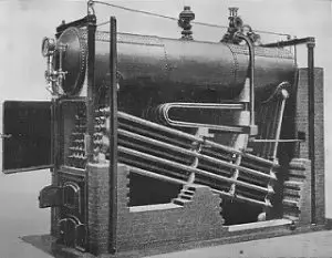
Babcock and Wilcox boiler diagram | Babcock and Wilcox boiler easy diagram | Babcock and Wilcox boiler images | Babcock and Wilcox boiler schematic diagram
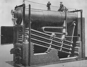
Babcock and Wilcox boiler
Babcock and Wilcox Boiler Credit Wikipedia
Babcock and wilcox schematic
Babcock and Wilcox Schematic
Image Credit Research gate Dr. Ravindran S., Shanmugam

Working of Babcock and Wilcox boiler

Lets’s learn the working of the Babcock and Wilcox boiler with details and stepwise.

  • The water is stored inside the drum. Then, the fluid initiates flowing from the steam –water drum to the incline water tubes (through the lower header).
  • The solid fuel burning in the furnace generates the hot flue gases passing over the water tubes. The water tube contains water in it which is get heated because of hot flue gases. Here, the baffles are very helpful to increase heat transfer. The hot gases pass through the zigzag motion due to baffles.
  • The water inside water tubes absorbs heat from hot flue gases and changes the phase from water to steam.
  • The produced steam inside the water tube will travel to the top and collected inside the topmost portion of the drum.
  • The function of an anti priming pipe is to reduce moisture content present in the steam. There are some holes inside the anti priming pipe, which is useful to lower the moisture. After separating moisture content, this pipe transfers the high pressure steam to the superheater for next steps.
  • The function of a superheater is to raise the temperature of the steam to make it suitable for power generation. Then, the super-heated steam is supplied to the steam stop valve pipe.
  • The steam from the superheater is either taken out or stored in the drum for another process. If the steam is taken out from the boiler, it is supplied to the turbine for power generation. The steam of boiler can be used for process heating purposes also.

Advantages of Babcock and Wilcox boiler | advantage of Babcock and Wilcox water tube boiler

The advantages of Babcock and Wilcox boiler are discussed in detail :

  • The efficiency of this boiler is more compared to others. The efficiency is expected around 60 to 80%
  • The generation of steam is higher in this boiler. It is approximately 20,000 to 40,000 kg of steam in one hour (Pressure range between 10 to 20 bar).
  • This boiler is easily maintainable compared to others.
  • It is easy to change the faulty tube in Babcock and Wilcox boiler.
  • The tube expansion and tube contraction cannot create problem in this boiler. The water drum and water tubes are loosely connected in the brick wall so that it is easy to expand and contract tubes during heat transfer.
  • The loss due to drought in Babcock and Wilcox boiler is very less.
  • The boiler inspection is convenient during boiler working.
  • It is easy to clean and repair every part of the Babcock and Wilcox boiler due to its better accessibility.
  • It is possible to obtain temperature and steam quickly in this boiler. Therefore, it is suitable to meet the quick demand for steam.
  • It can deliver highly dry steam even if the water supply is not proper compared to other boilers.
  • It requires less floor area per steam generation as compared with the fire tube boiler.

Disadvantages of Babcock and Wilcox boiler

There are some disadvantages of the Babcock and Wilcox boiler as discussed below in detail,

  • The water requires for the boiler should be very pure. Even a few impurities in the water can cause scale formation in water tubes. This scale formation results in a reduction in steam generation due to bursting and overheating. Before supplying water to the boiler, water treatment should be carried out to minimize the impurities.
  • It is required to monitor the water level continuously inside the boiler. If the feedwater level falls below the limit for few seconds, it can cause the overheating of tubes.
  • The Babcock and Wilcox boiler’s size is large compared to other boilers, resulting in the boiler’s maintenance cost.
  • The brick structure is required in this type of boiler, which is not necessary for other boilers.

Application of Babcock and Wilcox boiler | uses of Babcock and Wilcox boiler | Babcock and Wilcox boiler uses

This boiler is a stationary water tube boiler, so that it is normally utilized in stationary applications.

This type of boiler is utilized to develop higher pressure steam. This steam is utilized to electric power production.

Babcock and Wilcox boiler parts | Babcock and Wilcox water tube boiler | Babcock and Wilcox boiler model

There are many big and small parts in Babcock and Wilcox boiler. Out of them, some of the main components are listed and described as below,

Shell or Drum or water shell:

It is a cylindrical portion on top of the boiler. This drum is filled with water. The water level is maintained around 2/3 rd of the drum. The steam and water both stored in the drum during the operation of the boiler.

Water tubes (water pipes):

The water tubes are connected with the drum. The water tubes are installed inclined with the boiler to improve heat transfer and get other benefits. The water tubes is kept 15° angle of inclination. The diameter of the water tubes used in this boiler is about 10 cm.

Superheater:

The function of a superheater is to raise the temperature of the steam to make it suitable for power generation. Then, the super-heated steam is supplied to the steam stop valve pipe.

Furnace:

The Babcock Wilcox boiler is externally fired. The furnace of this boiler is built outside of the boiler structure. This furnace is built below the upper header.

Baffles :

The function of the baffles is to make gases passes over the tubes properly. It is also widely called a deflector. These baffles are made of bricks. The baffles are also useful to increase the effective contact area and time of contact between the water tubes and the hot flue gases.

Grate:

The grate is the cast iron made setup that is used inside the furnace. The solid fuel is spread over the grate for proper burning.

Fire Door:

The fire door is utilized to put fuel into furnace of the boiler. The solid fuel is generally provided through the fire door.

Anti -Priming Pipe (To remove moisture):

The function of an anti priming pipe is to reduce moisture content present in the steam. There are some holes inside the anti priming pipe, which is useful to lower the moisture.

Upper Header and Lower Header:

There are two headers in the Babcock and Wilcox boiler. One is the upper header, and the second is the lower header. The upper header and more downward header are joined with the drum through the water tubes.

The function of the upper header is to transfer the steam–water mixer to the drum. This header is joined to the front of the boiler.

The use of the lower header is to transfer fluid from the back end of the steam-water drum to the water tubes.

Mud Box:

The function of the mud box is to take mud and impurities from the water. It is installed below the lower header. Thus, the collected dirt is disposed of properly.

Man Hole:

The utility hole is a very important part of a boiler because it is the entry gate of a person to enter into the boiler. One can go inside the boiler and do cleaning and maintenance. The manhole should be kept close during boiler operation.

Blow Off Pipe:

The function of the blow-off pipe is used to take out all mud from the mud box. It is also draining water if found in an excessive way.

Supports:

The drum is installed with two supports because the drum carries water. In addition, the weight of the drum is high due to water storage. Therefore, supports are needed for the drum.

Babcock and Wilcox boiler specification

This boiler is available in the range of specifications. The common specification of the Babcock and Wilcox boiler is given below.

  • The thermal capacity of the boiler: 4 to 35 tons per hour
  • Pressure range: 1 to 2.5 MPa
  • The steam temperature at the output: 184 to 350 ℃
  • Acceptable fuel: Solid fuels like coal, woods etc.
  • Applications: Power industries, Petroleum industries, chemical industries for process heat, pharma and textile industries for process heating etc.

Babcock and Wilcox boiler accessories

The safety and performance of the boiler can be maintained with mountings and accessories. Mountings and the accessories of this boiler are discussed as below,

List of the mountings and accessories

  • Water level indicator (Indicate water level)
  • Steam Stop valve
  • Safety valve (To reduce pressure)
  • Superheater (Increase temperature)
  • Pressure gauge (Pressure measurement)

Water Level Indicator (Indicate water level)

The level of water inside the boiler should be maintained properly for efficient working of the boiler. The water level indicator indicates the how much water present inside the boiler at a time. The boiler operator continuously read the water level in the water level indicator.

Pressure measuring instrument

It is utilized to read the steam pressure in the boiler. The boiler operator continuously observes the pressure gauge during boiler operation.

Safety Valve

It is the most important device according to boiler safety. The safety valve installed on the steam chest. If the pressure inside the boiler will increase at the desired level, then this valve will open and release the pressure.

Superheater:

The function of a superheater is to raise the temperature of the steam to make it suitable for power generation. Then, the super-heated steam is supplied to the steam stop valve pipe.

Steam Stop Valve

A steam stop valve in this boiler is work to maintain the flow of produced steam. It is also useful to stop the steam output whenever required. It is one of the largest valve in the Babcock and Wilcox boiler. It is installed between the boiler and the main steam outlet line.

Babcock and Wilcox boiler pressure

The pressure inside Babcock and Wilcox boiler depends on the specification of the boiler. The operating pressure inside this type of boiler is generally in the range of 11.5to 17.5 bar.

Babcock and Wilcox boiler principle | construction and working of Babcock and Wilcox boiler

The water is kept in the water-steam drum. Then, the fluid starts leaving from the water-steam drum to the incline water tubes (through the lower header).

The solid fuel burning in the furnace generates the hot flue gases passing over the water tubes. The water tube contains water in it which is get heated because of hot flue gases. Here, the baffles are very helpful to increase heat transfer. The hot gases pass through the zigzag motion due to baffles.

The water inside water tubes absorbs heat from hot flue gases and changes the phase from water to steam.

The produced steam inside the water tube will travel to the top and collected inside the topmost portion of the drum.

The function of an anti priming pipe is to reduce moisture content present in the steam. There are some holes inside the anti priming pipe, which is useful to lower the moisture. After separating moisture content, this pipe transfers the high pressure steam to the superheater for next steps.

The function of a superheater is to raise the temperature of the steam to make it suitable for power generation. Then, the super-heated steam is supplied to the steam stop valve pipe.

The steam from the superheater is either taken out or stored in the drum for another process. If the steam is taken out from the boiler, it is supplied to the turbine for power generation. The steam produced from Babcock and Wilcox can be utilized for process heating applications also.

FAQS

Where Babcock and Wilcox boiler is used ?

The Babcock and the Wilcox boiler is generally used in the following applications,

Applications: Power industries, Petroleum industries, chemical industries for process heat, pharma and textile industries for process heating etc.

Power generation is a wide application of this boiler.

Who founded Babcock ?

Hero was a mathematician and scientist in greek. He has developed equipment working on the steam. Later on, it became known as the steam engine. Hero’s science is used to build the water tube boiler. Stephen Wilcox is the person who developed this boiler.

Which types of fuel can be used in Babcock and Wilcox boiler?

There are many fuels can be used for Babcock and Wilcox boiler. However, the coal is most widely used fuel for this boiler.

What will happen if the heat exchanger tube of the Babcock and Wilcox boiler is replaced by a cube?

A heat exchanger tube provides a more effective heat transfer area as compared to a cube. If a cube is used instead of a heat exchanger tube, the performance of the boiler will be decreased

Why are the tubes of water tube boilers kept inclined? Justify

The water tubes are joined with the water steam drum. The water tubes are installed inclined with the boiler to improve heat transfer and get other benefits. The water tubes is kept 15° angle of inclination. The tube diameter of the water tubes installed in this boiler is approx. 10 cm.

The inclination of the tube is encouraging the convection heat transfer in the tube.

For More Articles on Mechanical Engineering , Click Here
Mutual Inductance Transformer: 17 Important Concepts

CodeCogsEqn 45 convert.io

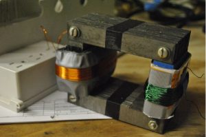
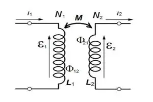
Mutual inductance is a fundamental concept in the field of electromagnetism. It refers to the phenomenon where a changing current in one coil induces a voltage in another nearby coil. This occurs due to the magnetic field produced by the first coil, which cuts across the turns of the second coil, resulting in the generation of an electromotive force. Mutual inductance plays a crucial role in various applications, including transformers, inductors, and wireless power transfer systems. Understanding mutual inductance is essential for designing efficient and reliable electrical circuits.

Key Takeaways

Mutual Inductance
– Induced voltage in one coil due to a changing current in another coil
– Occurs due to the magnetic field produced by the first coil
– Essential for transformers, inductors, and wireless power transfer systems

Understanding Mutual Inductance

Mutual inductance is a fundamental concept in the field of electromagnetic induction, which is governed by Faraday’s law. It describes the interaction between two coils or inductors that are in close proximity to each other. This phenomenon occurs when the magnetic field generated by one coil induces a voltage in the other coil. Mutual inductance plays a crucial role in various electrical circuits and devices, such as transformers and inductive coupling.

What is Self and Mutual Inductance?

CodeCogsEqn 45 convert.io

Before delving into mutual inductance, it is essential to understand the concept of self-inductance. Self-inductance refers to the ability of a coil or inductor to generate an electromotive force (EMF) in itself when the current flowing through it changes. This self-induced EMF opposes any change in the current, following the principles of electromagnetic induction.

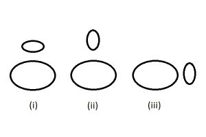
On the other hand, mutual inductance occurs when the changing magnetic field produced by one coil induces a voltage in another nearby coil. The induced voltage in the second coil depends on the rate of change of the magnetic field and the number of turns in the coil. The mutual inductance between two coils is influenced by their physical proximity and the alignment of their magnetic fields.

Mutual Inductance Formula

CodeCogsEqn 44 convert.io

The mutual inductance between two coils can be calculated using the following formula:

Mutual Inductance Formula

Where:
– M represents the mutual inductance
– V2
is the induced voltage in the second coil
– ΔI1
is the change in current in the first coil

The unit of mutual inductance is the Henry (H), named after Joseph Henry, a pioneer in the field of electromagnetism.

Mutual Inductance of Two Solenoids

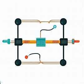
When considering the mutual inductance between two solenoids, several factors come into play. The mutual inductance depends on the number of turns in each solenoid, the radius of the solenoids, and their separation distance. By adjusting these parameters, the mutual inductance can be increased or decreased.

Reciprocity Properties of Mutual Inductance

One of the interesting properties of mutual inductance is reciprocity. This means that the mutual inductance between two coils remains the same regardless of which coil is considered the primary and which is considered the secondary. In other words, the induced voltage in one coil due to the magnetic field of the other coil is the same as the induced voltage in the second coil due to the magnetic field of the first coil.

Mutual Inductance Equivalent Circuit

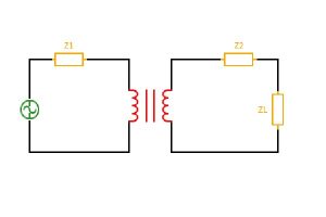
In electrical circuits, mutual inductance can be represented using an equivalent circuit. This circuit includes inductors that account for the mutual inductance between different parts of the circuit. By incorporating mutual inductance into the circuit analysis, engineers can accurately predict the behavior of complex electrical systems.

Understanding the physics of inductance and the role of mutual inductance is crucial in the field of electrical engineering. It allows engineers to design efficient transformers, analyze the reactance and impedance of circuits, and explore the concept of resonance. Moreover, inductance calculations and the understanding of electromagnetic energy transfer are essential for various applications in electrical engineering.

In summary, mutual inductance is a fundamental concept in electromagnetism that describes the interaction between two coils or inductors. It plays a vital role in the functioning of electrical circuits and devices, and its understanding is crucial for engineers in the field of electrical engineering.

Mutual Inductance in Transformers

Mutual inductance is a fundamental concept in the field of electrical engineering, particularly in the study of transformers. It is based on the principle of electromagnetic induction, which was first discovered by Michael Faraday in the early 19th century. Mutual inductance refers to the phenomenon where the magnetic field produced by one coil induces a voltage in another nearby coil.

How is Mutual Inductance Used in a Transformer?

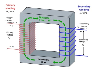
In a transformer, mutual inductance plays a crucial role in the transfer of electrical energy from one circuit to another. A transformer consists of two or more coils, known as windings, which are wound around a common magnetic core. When an alternating current flows through the primary winding, it creates a changing magnetic field. This changing magnetic field induces a voltage in the secondary winding, allowing for the transfer of electrical power.

Mutual Inductance Transformer Formula

CodeCogsEqn 49 convert.io

The mutual inductance between two coils can be calculated using the following formula:

M = k * √(L1 * L2)

Where M is the mutual inductance, k is the coefficient of coupling (ranging from 0 to 1), L1 is the self-inductance of the first coil, and L2 is the self-inductance of the second coil. This formula quantifies the extent to which the magnetic field of one coil links with the other coil.

Self-Inductance and Mutual Inductance of an Ideal Transformer

CodeCogsEqn 52 convert.io

In an ideal transformer, the primary and secondary windings have perfect mutual inductance, meaning that all the magnetic flux produced by the primary winding is linked with the secondary winding. Additionally, each winding has self-inductance, which is a measure of the coil’s ability to store energy in its magnetic field. The self-inductance of a coil is determined by its physical properties, such as the number of turns and the core material.

Single-Phase and Three-Phase Transformer

Transformers can be categorized based on the number of phases they handle. A single-phase transformer is designed to transfer power between two single-phase alternating current systems. On the other hand, a three-phase transformer is used in three-phase power systems, which are commonly found in industrial and commercial applications. Three-phase transformers are more efficient and compact compared to single-phase transformers.

Auto-Transformer Definition

An auto-transformer is a type of transformer that has a single winding, which serves as both the primary and secondary winding. It is designed to step up or step down the voltage in electrical circuits. Auto-transformers are commonly used in applications where a small voltage adjustment is required, such as in voltage regulators and variable speed drives.

In conclusion, mutual inductance is a fundamental concept in transformers, enabling the efficient transfer of electrical energy between circuits. Understanding the principles of mutual inductance and its application in transformers is essential in the field of electrical engineering.

Practical Applications and Problems

Electromagnetic induction, based on Faraday’s law, is a fundamental concept in physics and electrical engineering. It has numerous practical applications and can also pose certain challenges. Let’s explore some of the practical applications and problems related to electromagnetic induction.

Mutual Inductance Circuit Problem

One common problem encountered in electrical circuits is the issue of mutual inductance. Mutual inductance occurs when two or more coils are placed close to each other, resulting in the magnetic field generated by one coil inducing a voltage in the other coil. This can lead to unwanted effects such as crosstalk or interference between circuits.

To solve mutual inductance circuit problems, the mutual inductance formula is often used. This formula calculates the mutual inductance between two coils based on their geometrical arrangement and the magnetic flux linking them. By understanding the principles of mutual inductance, engineers can design circuits that minimize or eliminate these unwanted effects.

Numerical Problems on Mutual Inductance

CodeCogsEqn 51 convert.io

To further understand and apply the concept of mutual inductance, numerical problems can be solved. These problems involve calculating the mutual inductance between coils of different shapes and sizes. By solving these problems, engineers can gain a deeper understanding of the factors that affect mutual inductance and how to manipulate them to achieve desired outcomes in circuit design.

How to Insulate Two Coils to Prevent Mutual Inductance?

In certain situations, it may be necessary to insulate two coils to prevent mutual inductance. This can be achieved by using materials with high magnetic permeability, such as mu-metal, to shield the coils from each other’s magnetic fields. Additionally, physically separating the coils or using non-magnetic materials between them can also help reduce mutual inductance.

How to Achieve Zero Inductance?

While it is not possible to achieve zero inductance in a practical sense, it is possible to minimize its effects. This can be done by designing circuits with low inductance values or by using techniques such as inductive coupling, where the magnetic fields of two coils are intentionally coupled to transfer energy between them. By carefully controlling the parameters of the circuit, engineers can achieve a near-zero inductance effect.

Can Mutual Inductance be Negative?

Mutual inductance is a positive quantity that represents the coupling between two coils. It is not possible for mutual inductance to be negative. However, it is important to note that the induced voltage in the secondary coil can have a polarity opposite to that of the primary coil, depending on the direction of the magnetic field and the relative orientation of the coils.

In conclusion, understanding and managing mutual inductance is crucial in the design and operation of electrical circuits. By applying the principles of electromagnetic induction and utilizing techniques to minimize its effects, engineers can ensure the efficient and reliable functioning of various electrical systems.

Advanced Concepts

ckmi3 1

In the field of electrical engineering, there are several advanced concepts related to electromagnetic induction and coil inductance that are worth exploring. These concepts include mutual inductance of parallel wires, methods to reduce mutual inductance, mutual inductance coupling coefficient, derivation of mutual inductance, and the formula for calculating mutual inductance of two coils. Let’s delve into each of these concepts in more detail.

Mutual Inductance of Parallel Wires

Mutual inductance refers to the phenomenon where the magnetic field produced by one coil induces a voltage in another coil. When two parallel wires carry electrical currents, they generate magnetic fields that interact with each other. The mutual inductance of parallel wires describes the extent to which these magnetic fields influence each other. It plays a crucial role in understanding the behavior of electrical circuits and is governed by Faraday’s law of electromagnetic induction.

How to Reduce Mutual Inductance?

In certain situations, it may be desirable to reduce the mutual inductance between two parallel wires. This can be achieved through various methods. One approach is to increase the distance between the wires, as the magnetic field strength decreases with distance. Another method involves twisting the wires together, which helps to cancel out the magnetic fields generated by each wire. Additionally, using shielding materials can effectively reduce the mutual inductance by confining the magnetic fields within the wires.

Mutual Inductance Coupling Coefficient

The mutual inductance coupling coefficient is a measure of the coupling efficiency between two coils. It quantifies the extent to which the magnetic field produced by one coil links with the other coil. The coupling coefficient ranges from 0 to 1, where 0 indicates no coupling and 1 represents perfect coupling. It is an important parameter in the design and analysis of transformers and inductive coupling systems.

Mutual Inductance Derivation

The derivation of mutual inductance involves mathematical calculations based on the principles of electromagnetic induction. It takes into account factors such as the number of turns in the coils, the magnetic flux linking the coils, and the geometry of the coils. By understanding the derivation of mutual inductance, one can gain insights into the physics of inductance and its role in electrical circuits.

Mutual Inductance of Two Coils Formula

The mutual inductance between two coils can be calculated using a formula that takes into account various parameters. The formula involves the number of turns in each coil, the magnetic flux linking the coils, and the geometrical arrangement of the coils. This formula is widely used in the design and analysis of transformers, where mutual inductance plays a crucial role in transferring electrical energy from one coil to another.

By understanding these advanced concepts related to mutual inductance, one can gain a deeper insight into the physics of inductance and its applications in electrical engineering. These concepts are fundamental to the study of electromagnetic fields, reactance, impedance, resonance, and the calculation of inductance in various electrical systems.

Frequently Asked Questions

Is Mutual Inductance Always Positive?

No, mutual inductance can be positive or negative depending on the orientation of the coils and the direction of the current. Mutual inductance is a measure of the interaction between two coils and is defined as the ability of one coil to induce a voltage in the other coil. If the current in one coil produces a magnetic field that reinforces the magnetic field of the other coil, the mutual inductance is positive. Conversely, if the magnetic fields oppose each other, the mutual inductance is negative.

Does Mutual Inductance Depend on Current?

Yes, mutual inductance depends on the current flowing through the coils. According to Faraday’s law of electromagnetic induction, the induced voltage in a coil is directly proportional to the rate of change of magnetic flux through the coil. Therefore, the greater the current flowing through a coil, the stronger the magnetic field it produces, and the higher the mutual inductance between the coils.

How to Measure Mutual Inductance?

Mutual inductance can be measured using various techniques. One common method is to connect the two coils in series and apply an alternating current to one of the coils. By measuring the voltage induced in the other coil, the mutual inductance can be determined. Another method involves using a mutual inductance bridge circuit, which allows for more precise measurements. Additionally, mutual inductance can also be calculated indirectly by measuring the self-inductance of each coil and using the mutual inductance formula.

How to Calculate Mutual Inductance of a Transformer?

The mutual inductance of a transformer can be calculated using the formula:

M = (k * √(L1 * L2))

Where M is the mutual inductance, k is the coupling coefficient (a value between 0 and 1 that represents the degree of magnetic coupling between the coils), L1 is the self-inductance of one coil, and L2 is the self-inductance of the other coil. The mutual inductance is typically measured in henries (H).

Difference Between Mutual Induction and Mutual Inductance

Mutual induction and mutual inductance are related concepts but have distinct meanings. Mutual induction refers to the process by which a changing current in one coil induces a voltage in another coil. It is a fundamental principle of electromagnetic induction and is the basis for the operation of transformers and inductive coupling in electrical circuits.

On the other hand, mutual inductance is a quantitative measure of the interaction between two coils. It represents the ability of one coil to induce a voltage in the other coil and is determined by factors such as the number of turns, the orientation of the coils, and the current flowing through them. Mutual inductance is calculated using the mutual inductance formula and is expressed in henries (H).

In summary, mutual induction is the phenomenon, while mutual inductance is the measure of that phenomenon. Understanding the concepts of mutual induction and mutual inductance is essential in the study of inductors, transformers, and the physics of inductance in electrical engineering.

Conclusion

In conclusion, mutual inductance is a fundamental concept in the field of electromagnetism. It refers to the phenomenon where a changing current in one coil induces a voltage in another nearby coil. This mutual interaction between the coils is crucial in various applications, such as transformers and inductors.

Mutual inductance plays a vital role in the efficient transfer of energy between different circuits. It allows for the transformation of voltage levels, enabling the transmission of electrical power over long distances. Additionally, mutual inductance is utilized in devices like electric motors and generators, where the conversion of electrical energy to mechanical energy is required.

Understanding mutual inductance is essential for engineers and scientists working in the field of electronics and electrical engineering. It provides the foundation for designing and analyzing complex circuits and systems. By grasping the principles of mutual inductance, we can harness its power to create innovative technologies that shape our modern world.

Multiple Choice Questions

MCQ on Inductor

  1. What is an inductor?
  2. A. A device that stores electrical energy in a magnetic field
  3. B. A device that converts electrical energy into mechanical energy
  4. C. A device that generates electrical energy from light
  5. D. A device that regulates the flow of current in a circuit

  6. Which of the following is true about inductance?

  7. A. It is the property of a circuit that opposes changes in current
  8. B. It is the property of a circuit that allows easy flow of current
  9. C. It is the property of a circuit that converts electrical energy into mechanical energy
  10. D. It is the property of a circuit that regulates the voltage

  11. What is the unit of inductance?

  12. A. Ampere (A)
  13. B. Ohm (Ω)
  14. C. Henry (H)
  15. D. Volt (V)

  16. Which formula is used to calculate the inductance of a coil?

  17. A. Ohm’s Law
  18. B. Faraday’s Law
  19. C. Henry‘s Law
  20. D. Coulomb’s Law

MCQ on Mutual Inductance Transformer Related

CodeCogsEqn 55 convert.io
  1. What is mutual inductance?
  2. A. The property of a circuit that opposes changes in current
  3. B. The property of a circuit that allows easy flow of current
  4. C. The property of a circuit that converts electrical energy into mechanical energy
  5. D. The property of a circuit that relates the change in current in one coil to the change in current in another coil

  6. What is a transformer?

  7. A. A device that stores electrical energy in a magnetic field
  8. B. A device that converts electrical energy into mechanical energy
  9. C. A device that generates electrical energy from light
  10. D. A device that transfers electrical energy between two or more coils through electromagnetic induction

  11. How is mutual inductance calculated in a transformer?

  12. A. By using Faraday’s Law
  13. B. By using Ohm’s Law
  14. C. By using Henry’s Law
  15. D. By using Coulomb’s Law

  16. What is inductive coupling?

  17. A. The transfer of energy between two coils through mutual inductance
  18. B. The transfer of energy between two coils through self-inductance
  19. C. The transfer of energy between two coils through capacitive coupling
  20. D. The transfer of energy between two coils through resistive coupling

Remember to choose the most appropriate answer for each question. Good luck!

Detailed Solutions to Problems and MCQs

Welcome to the detailed solutions section, where we will explore various problems and multiple-choice questions related to electromagnetic induction, Faraday’s law, and other concepts in the field of inductance. Let’s dive right in!

[]

In this section, we will focus on the concept of electromagnetic induction and its applications. Electromagnetic induction is the process of generating an electromotive force (emf) in a conductor when it is exposed to a changing magnetic field. This phenomenon, discovered by Michael Faraday, forms the basis of many electrical devices and plays a crucial role in electrical engineering.

To understand the principles of electromagnetic induction, let’s start with a simple example. Imagine we have a coil of wire and a magnet. When we move the magnet towards the coil, the magnetic field passing through the coil changes. This change in magnetic field induces an emf in the coil, causing an electric current to flow. This is the basic principle behind generators and electric motors.

Now, let’s move on to some problems and multiple-choice questions to test our understanding of electromagnetic induction and related concepts. Here are a few examples:
  1. Problem: Calculate the magnetic field strength inside a solenoid with 500 turns and a current of 2A flowing through it.
    Solution: We can use the formula for the magnetic field inside a solenoid, which is given by B = μ₀ * n * I, where B is the magnetic field strength, μ₀ is the permeability of free space, n is the number of turns per unit length, and I is the current. Plugging in the values, we get B = (4π * 10^-7 T*m/A) * (500 turns/m) * (2A) = 0.004 T.

  2. Multiple-Choice Question: Which of the following is an example of inductive coupling?
    a) Capacitor
    b) Transformer
    c) Resistor
    d
    ) Diode
    Answer
    : b) Transformer

  3. Problem: Calculate the self-inductance of a coil with an inductance of 5 H and a current changing at a rate of 2 A/s.
    Solution
    : We can use Faraday’s law of electromagnetic induction, which states that the emf induced in a coil is equal to the rate of change of magnetic flux through the coil. The formula for self-inductance is L = Φ/I, where L is the self-inductance, Φ is the magnetic flux, and I is the current. Rearranging the formula, we get Φ = L * I. Plugging in the values, we get Φ = (5 H) * (2 A/s) = 10 Wb.

These are just a few examples to give you an idea of the types of problems and multiple-choice questions you may encounter when studying electromagnetic induction and inductance. Remember to practice and understand the underlying concepts to excel in this field.

In conclusion, electromagnetic induction and the concepts of inductance play a crucial role in electrical circuits and the field of electrical engineering. Understanding the principles behind electromagnetic induction, Faraday’s law, and other related concepts is essential for designing and analyzing electrical systems. So keep exploring and learning more about the fascinating world of inductance and its applications!

Frequently Asked Questions

1. Can mutual inductance be negative?

No, mutual inductance cannot be negative. It is a measure of the amount of magnetic flux generated in one coil due to the change in current in another coil. It is always a positive value, as it is based on the absolute value of the magnetic field interaction between the two coils.

2. What is the mutual inductance formula?

ckmi2

The mutual inductance formula is M = N2Φ/I1, where M is the mutual inductance, N2 is the number of turns in the second coil, Φ is the magnetic flux through one loop of the second coil, and I1 is the current in the first coil.

3. What does mutual inductance mean?

Mutual inductance is a property that exists between two coils when the change in current in one coil induces a voltage in the other coil. It is a fundamental concept in electromagnetic induction and is measured in Henrys (H).

4. How to measure mutual inductance with an LCR meter?

To measure mutual inductance with an LCR meter, connect the two coils in series and measure the total inductance. Then, reverse the connections of one coil and measure the inductance again. The difference between these two measurements divided by 4 gives the mutual inductance.

5. How does mutual induction occur?

Mutual induction occurs when a change in current in one coil induces a voltage in a nearby coil. This happens due to the magnetic field produced by the current-carrying coil, which links with the turns of the nearby coil and induces a voltage in it according to Faraday’s law of electromagnetic induction.

6. What is the mutual inductance of a pair of coils?

ckmi

The mutual inductance of a pair of coils is a measure of how much a change in current in one coil will induce a voltage in the other coil. It depends on factors like the number of turns in each coil, the area of the coils, the distance between the coils, and the medium in which the coils are located.

7. How to reduce mutual inductance?

Mutual inductance can be reduced by increasing the distance between the coils, decreasing the number of turns in the coils, or orienting the coils so that their magnetic fields do not interact significantly.

8. What is the mutual inductance in a transformer?

In a transformer, the mutual inductance is the property that allows the transfer of energy from the primary coil to the secondary coil. It is a measure of how effectively the magnetic field generated by the primary coil induces a voltage in the secondary coil.

9. What is the symbol for mutual inductance?

The symbol for mutual inductance is ‘M’. It is measured in Henrys (H).

10. How is the mutual inductance of a pair of coils affected when the distance between them changes?

The mutual inductance of a pair of coils decreases as the distance between them increases. This is because the magnetic field generated by one coil has less effect on the other coil when they are further apart.

13 Vital Facts on D Flip Flop: Circuit, Truth Table, Working

d flip flop

A D Flip Flop stores a single bit of data; its output mirrors the input (D) when the clock (CLK) is high. Truth table: When CLK=1, if D=0, output Q=0, if D=1, Q=1; When CLK=0, Q remains unchanged. It’s edge-triggered, changing state only at clock edges, ensuring stable data storage and synchronization in digital circuits. Ideal for shift registers, data storage, and synchronizing asynchronous inputs.

A flip flop is the fundamental sequential circuit element, which has two stable states and can store one bit at a time. It can be designed using a combinational circuit with feedback and a clock. D Flip-Flop is one of that Flip Flop that can store data. It can be used to store data statically or dynamically depends on the design of the circuit. D Flip-Flop is used in many sequential circuits as register, counter, etc.

What is D flip flop ?

D flip-flop or Data flip flop is a type of flip Flop that has only one data input that is ‘D’ and one clock pulse input with two outputs Q and Q bar. This Flip Flop is also called a delay flip flop because when the input data is provided into the d flip-flop, the output follows the input data delay by one clock pulse.

d type flip flop

Full Form of D flip flop

D stands for Delay or Data in D flip-Flop.

D flip flop Diagram

The given circuit represents the D flip-flop circuit diagram, where the whole circuit is designed with the help of the NAND gate. Here the output of one NAND gate is feed as one input to the other NAND gate, which forms a latch. Then, the latch is gated with two more NAND gates where D is one input and clock is the other input. 
d flip flop
Fig. Circuit diagram of the D flip-flop designed with NAND gate

The final output of the D flip-flop is Q and Qbar, where Qbar is always complementary to Q.
D Flip Flop Truth Table
What is D Flip Flop Truth Table ?

The truth table of the d flip flop shows every possible output of the d flip-flop with the all possible combination of the input to the d flip flop, where Clock and D is the input to the D flip-flop and Q and Qbar is the output of the D flip-flop.

CLOCKDQQbar
00NO CHANGENO CHANGE
01NO CHANGENO CHANGE
1001
1110

D flip flop Excitation Table

The exaltation table or state table shows the minimum input with respect to the output that can define the circuit. Which mainly represents a sequential circuit with its present and next state of output with the preset input and clock pulse. This table is also known as a characteristic table for D flip-flop.

DinCLKPresent state ‘Q’Next state ‘Q’
X000
X011
0100
0110
1101
1111

D flip flop Boolean Expression

The boolean expression of the D flip-flop is Q(t+1)=D because the next value of Q is only dependent on the value of D, whereas there is a delay of one clock pulse from input D to output Q.

d flip flop
Fig. K- map of input (D) and output (Q) of the D flip-flop

How D Flip Flop Works ?

Working of D flip flop

D Flipflop is a bi-stable memory element, which can store one bit at a time, either ‘1’ or ‘0’. When the D input is provided to the Flip Flop, the circuit check for the clock signal is the signal of the clock is high ( for level triggered d flip-flop) then with every clock pulse, the input D propagates to the output Q. 

For edge triggered flip-flop, the circuit check for the transition of clock pulse according to which the flip Flop propagates the input to the output; edge triggered can be positive edge triggered or negative triggered. Positive edge triggered D flip-flop changes its output according to input with every transition of the clock pulse from 0 to 1. As for the negative edge triggered D flip-flop changes its output according to input with every transition of the clock pulse from 1 to 0.

D flip flop Timing Diagram

As shown in the given figure, there is a clock pulse representation, with which D, which is the input to D flip-flop, and Q which is the output, is represented, where Qbar is the complement output of the output Q, here we see the timing diagram of a positive edge flip flop, that’s why here the output changes with every positive transition in the clock pulse according to the input.

image 13
Fig. Timing or Waveform diagram of the D flip-flop (positive edge triggered).

D flip flop Block Diagram

The diagram shown below is the block representation of the d flip-flop, where D is the input, the clock is another input to the Flip Flop, where a preset and clear signal is used to set or reset the output Q of the D flip-flop. 

What is D flip flop Symbol ?

image 14
Fig. Block representation of the D flip-flop with preset and clear

D flip flop Clear and Preset

The given figure is the block diagram of a D flip-flop having preset/set and rest / clear as additional input to the Flip Flop, where Preset/Set is used to set the output Q of the flip Flop set to 1. Rest/Clear is to set the output Q of the flip Flop to 0.

image 15
Fig. Block diagram of the D flip-flop with preset/set and reset/clear

D flip flop with Set

D flip-flop can have set the input as a requirement, and it can change the output and set the output Q to 1. It can be synchronous or asynchronous, Synchronous when the output can change only with the clock pulse, asynchronous is when the output can be set to 1 at any point of time regardless of the clock pulse.

D flip flop with Reset

D flip-flop can sometimes reset / clear input only in addition to data input and clock input, resetting the output Q to zero of the d flipflop as a requirement. Reset/Clear be active low input or active high input depends on the Flip Flop design.

Asynchronous Set and Reset

D flip flop with Asynchronous Set and Reset

D flip-flop can have an asynchronous set/preset and reset/clear as input independent of the clock. That means the output of the Flip Flop can be set to 1 with preset or reset to 0 with the reset despite the clock pulse, which means the output can change with or without a clock, which can result in asynchronous output.

D flip flop with Asynchronous Reset

D flip-flops can have asynchronous reset, which can be independent of the clock. Regardless of the clock, the reset can change the output Q to zero, which can cause asynchronous output.

D flip flop with Synchronous Reset

D flip-flop with synchronous reset means the output can reset to zero with the reset input but only with the clock, which makes the reset input dependent on the clock pulse; without clock pulse reset will not be able to set the output Q to zero, which will give you a synchronous output always.

D Flip Flop with Enable

Other than set/preset or reset/clear D flip-flop can have enabled as one input when enable is high, the Flip Flop can operate with the data input and clock input, but when the enable is low then regardless of any other input, the flip Flop stays in a hold state.

image 16
Fig. Block representation of a D flip-flop with Enable

D flip flop with Enable Truth Table

EnableDQn01NO CHANGE00NO CHANGE111100Table: D flip-flop truth table with enable input


D flip flop Truth Table with Preset and Clear

PR (ACTIVE LOW)CLR(ACTIVE LOW)CLKDQQbar
01XX10
10XX01
00XXNOT DEFINEDNOT DEFINED
111110
111001
111XNO CHANGENO CHNAGE
Table: D flip-flop table with preset, clear and clock

D flip flop Truth Table with Clock and Reset

CLKRESETDQ
0XXNO CHANGE
11X0
1011
1000
Table: D flip-flop Truth table reset and clock input

Asynchronous D flip flop

When D flip-flop generates output independent of the clock signal, then the output produced may be asynchronous. It is mainly caused by an asynchronous set/preset or clear/reset signal, which can set or reset the output of the flip Flop at any intent of time, which disrupt synchronicity in the D flip-flop.

State Diagram for D Flip Flop

The state diagram is the representation of a different stable state with the transition between the states with the cause of transition. Here every stable state output of the D flip-flop is represented with a circle. In contrast, the transition between the state is represented by the arrow between the circle, which is leveled with the cause of the transition.

image 17
Fig. State diagram of the D flip-flop

When the state changes from 0 to 1, it is caused by the input D, which is high, and when the output state is 0, and at the time D=0 that produces no change in the output, the arrow with D=0 starts with state 0 and also returns to state 0.

ASM Chart for D flip flop

An algorithmic state machine chart contains three blocks: state block, condition block, and conditional output box. The rectangle box represents one state; the diamond box is the condition box true or false if the condition decides the branch to follow.

image 18
Fig. ASM (algorithmic state machine) chart representation of the D flip-flop

D flip flop schematic | D Flip Flop Schematic Circuit | D Type Flip Flop Schematic

The figure shows the schematic representation of the D flip-flop; the schematic diagram represents the procedure using abstract. 

Two diagrams show the working of the D flip-flop when the clock is high and another showing when the clock is low. When the clock is high, the input data passes through the circuit, but when the clock is low, the input can not pass through the circuit, which shows regardless of the change in input, there will be no change in output when the clock is low.

image 19
Fig. Schematic diagram representation of the d flip-flop. one figure with clock pulse low and other with clock pulse high

Dynamic D flip flop

Flip Flop is generally a static storing device, but a dynamic flip flop can dynamically store data. In the given schematic diagram of a dynamic flip flop, we can see a capacitor connected to each stage. When there is no clock pulse for a long time, the capacitor’s charge can be lost. However, because of the presence of the capacitor, the circuit will be able to store data dynamically.

image 20
Fig. A Schematic diagram of the Dynamic D flip-flop

Dynamic D flip-flop is designed for faster operation; the area covered by dynamic flip flop is less than that of a static flip flop.

D flip flop Metastability

Metastability refers to the state where output is not deterministic. It can cause oscillation, unclear transitions in the circuitry. For example, flip Flop faces the problem of metastability; it happens to a flip flop when the clock pulse and data change at the same instate of time, which causes the result to behave unpredictably.

To avoid metastability in flip Flop the operation of flip Flop should operate considering the setup time and hold time of the Flip Flop. Still, metastability cannot be eliminated completely, but it can be minimized.

Application of D flip flop

Important applications of D flipflop listed as follows :

  • D flip-flop can be used to produce a controlled delay in the circuitry.
  • Used to design frequency divider circuity.
  • For creating counters.
  • For developing registers.
  • Used in pipelining.
  • For synchronization.
  • Can be used to avoid glitches.
  • Used to fix clock frequency as for the requirement of the circuitry.
  • Can be used for isolation.
  • As Toggle switch.
  • Can be used for Data transmission.
  • Sequence generator.
  • Can be used as a memory element.

Difference Between D and T flip flop

D FLIP-FLOPT FLIP FLOP
The output of a d flip flop follows the input with a delay of one clock pulse.The output of T flip flop toggles with a high input with every clock pulse.
It is known as delay flip flopIt is known as toggle flip flop
With low input the output also changes to low with clock pulseWith low input the output does not change at all, it stays in hold state.

Difference Between D flip flop and JK flip flop

D flip-flopJ K flip flop
The output of a d flip flop follows the input with a delay of one clock pulse.The output of a J K flip flop sets to 1 with J and resets to 0 with R  when there is clock pulse.
It is known as delay flip flop.It is also called universal flip flop.
It has less number of input combinations.It has more number of input combinations.

Difference Between D latch and D flip flop

D latchD flip-flop
D latch is a gated SR latch, which do not have clock input D flip-flop is combination of D latch with clock input
Less complex circuitComplex circuit
D latch is has enable signal which can enable or disable the latch operationD flip-flop has clock signal which can hold or operated the flip flop when no set or reset input is available.
D latch can be active high input or active low input latch.D flip-flop in which data input is always active high, where set or reset input can be active high or active low input.
D latch is always a level triggered circuit.D flip-flop can be level triggered or edge triggered circuit.
Less number of transistor is required for design.More number of transistor is required for design.
Asynchronous in nature.Generally synchronous in nature.

Q: What is a flip-flop in digital electronics?

A: In digital electronics, a flip-flop or latch is a circuit that has two stable states and can be used to store state information. They are fundamental building blocks in sequential logic, with the D-type flip flop being a commonly-used type.

Q: What is a d-type flip flop?

A: A D-type flip flop is a type of flip flop circuit that has a D (data) input and a clock input. The D flip-flop captures the value of the D-input at a definite portion of the clock cycle (such as the rising edge). This can be thought of as the flip flop “sampling” the D input and storing it.

Q: How do logic gates interact in a d-type flip flop?

A: A D-type flip flop can be implemented using a combination of logic gates such as AND and OR gates, as well as inverters. The particular arrangement of these gates determines the output of the flip-flop for each input condition.

Q: What distinguishes a d-type flip flop from an sr flip-flop?

A: One key difference is that an SR flip-flop requires two inputs, namely S (Set) and R (Reset), while a D-type flip flop takes both a data input and a clock input. Consequently, the behaviour and use cases of these flip flop types are different in digital electronics.

Q: Can you explain the working of a D flip-flop action on the rising edge of the clock?

A: The D flip-flop is sensitive to the clock edge, i.e., the transition from low to high (rising edge) or high to low (falling edge). When the clock signal goes from low to high on the rising edge, the value on the D input is transferred to the flip-flop’s output. At other times, the output remains what was last stored.

Q: How does a D flip flop compare to a JK flip-flop?

A: The JK flip-flop and the D type flip-flop are two types of flip-flops in digital electronics. The JK flip-flop, like the SR flip-flop, has two inputs but does not have the invalid state that the SR flip-flop has when both inputs are 1. The D flip-flop, on the other hand, eliminates this ambiguity by having only one input that determines what state the flip flop will change to, with the change in state being triggered by a clock edge.

Q: How does a D flip-flop function in shift registers?

A: In a shift register, multiple D flip-flops are chained together in a configuration known as a cascade. Each flip-flop passes its output as the input to the next flip-flop on each clock cycle, effectively shifting the binary data held by the register.

Q: What is a truth table in the context of a D flip-flop?

A: A truth table for a D flip-flop is a table that describes how the output of the flip-flop depends on its current output and current input. For a D-type flip-flop, the next state is exactly what the data input is at the time of a positive clock edge.

Q: What is the characteristic equation of a D flip- flop?

A: The characteristic equation of a D flip-flop is simple: The next output Q(next) equals the current input D (Q(next) = D). This is as per data input from the flip flop at the time of a positive clock edge.

Q: How does a delay flip-flop (D FF) work?

A: A delay flip-flop (D FF), sometimes known as a D-type flip-flop, behaves just like a wire delayed by one clock period. It takes an input signal and outputs that same signal, but delayed by one clock cycle. In essence, the D FF “remembers” the input value at the rising edge of the clock and delays it by one clock cycle.

Q: What is an SR flip-flop in digital electronics?

A: An SR flip-flop, one of the types of flip-flops in digital electronics, is a form of a sequential logic circuit often utilized for data storage. An SR flip-flop requires two inputs, specifically, the set (S) and reset (R) inputs. The output changes or retains its state when it faces different input conditions, making it a fundamental building block of digital electronics.

Q: How does a D-type flip flop work?

A: A D-type flip-flop operates with a data input and a clock input. At the rising edge of the clock input, the d-type flip flop transfers the input data to the output. Thus, it acts as a delay or edge-triggered device in digital electronics, transmitting the data input from the flip flop’s input to its output during clock pulses.

Q: What is a JK flip-flop?

A: A JK flip-flop is another type of flip flop circuit found in digital logic. It extends the functionality of the SR flip flop by addressing the input condition issue where both inputs are 1. With a JK flip-flop, this state triggers a toggle, causing the flip flop to change state at every clock edge.

Q: What are logic gates, and how do they relate to flip flops?

A: Logic gates are fundamental building blocks in digital electronics that process binary inputs to produce a binary output based on the type of gate. Flip flops, including D-type and SR flip-flops, are composed of interconnected logic gates. The combination of these logic gates determines how a flip flop behaves in terms of its characteristic equation.

Q: Can flip flops be used as shift registers in digital logic?

A: Yes, flip flops can be utilized to implement shift registers in digital logic. A shift register is a sequential device that utilizes flip-flops to store binary data. In a shift register, data is passed from the output of one flip flop to the inputs of the next flip-flop in a cascade configuration, in synchronization with clock pulses.

Q: What are the input signals in a flip flop?

A: The input signals in a flip flop vary depending on the type of flip flop circuit used. For an SR flip-flop, the two inputs are known as set and reset. For a D-type flip-flop, the two inputs are data and clock. An additional input, known as ‘enable’, may be used in certain types of flip-flops.

Q: What happens when a flip flop receives a rising edge input signal?

A: When a flip flop receives a rising edge input signal, i.e., a transition from a low voltage to a high voltage, a state change typically occurs. In a D-type flip flop, for instance, the state of the data input is captured at the moment of the rising edge of the clock and is transferred to the output.

Q: What role does an inverter play in the operation of a flip flop?

A: An inverter, another basic block of digital electronics, plays a crucial role in the functioning of a flip flop. It is used in a flip flop circuit to invert the output, specifically, a high output becomes low, and vice versa. In the SR flip-flop, for instance, an inverted output from one part of the circuit is often looped back as an input to another part, creating a form of feedback that enables the flip flop to maintain its state.

Q: What is meant by ‘since the output of a flip flop would always change’?

A: When we say ‘since the output of a flip flop would always change’, we’re referring to the inherent characteristic of a flip flop as a bistable device. This means that it has two stable states and can transition between these states based on its input. Thus, depending on the input conditions and type of flip flop circuit, the output of the flip flop can change or retain its prior state, making it a crucial component in digital electronics where data storage and transfer are required.

Q: What leads a flip flop to change state?

A: A flip flop changes state based on its input signal(s). For instance, an SR flip-flop changes state when either the Set or Reset input is activated, and a D-type flip flop changes state based on the data input at the moment of a clock edge, especially a rising edge. The change state feature of flip flops makes them pivotal in designing digital systems for various applications, from basic data storage units to complex microprocessors.

Diesel Cycle: 17 Important Factors Related To It

Pv 300x182 1

Key highlights:

Content:

Diesel Cycle

The Diesel engine came into existence by Rudolph Diesel in 1892, and it was somewhat modification of the SI engine by eliminating the spark plug and introducing a fuel injector. The idea was to overcome the problem regarding air-fuel mixture compression and replace it with just air compression and suppling fuel at high-pressure, high-temperature air for the combustion process.

Diesel cycle definition

The diesel cycle or Ideal diesel cycle is the power-producing cycle that generates the power stork at constant pressure. It is used in Reciprocating internal combustion engines with fuel as Diesel.

Diesel combustion cycle

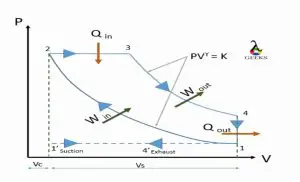
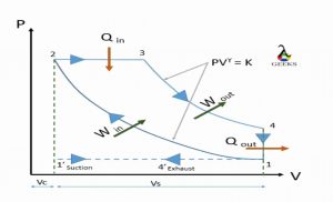
The work input required in the diesel cycle is for compression of air, and the work output is obtained by the combustion of fuel causing the power stroke. Combustion is considered to be at constant pressure (Isobaric process) resulting in increase of volume and temperature.

The process starts with sucking the atmospheric air into the cylinder, then the compression process takes place, resulting in increased pressure and temperature of the air.

At the end of this stage, the air is at a high temperature and high pressure, just a bit before the end of the compression stage, the fuel is added through the fuel injector. as the fuel comes in contact with this high-temperature, high-pressure air, it self-ignites, and the combustion stage occurs.

Combustion of enriching fuel results in the generation of power, which results in the power stroke, i.e., the piston is pushed back with high, resulting in work output than the last stage, i.e., exhaustion takes place, to let out the burnt gas in the cylinder.

And then, the process is repeated.

To get continuous output, we are required to arrange the number of cylinders rather than just one.

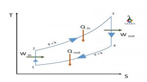
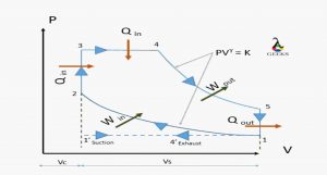
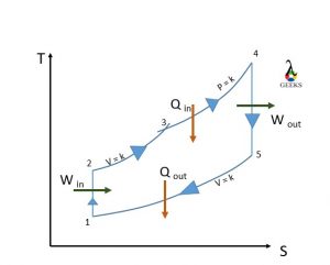
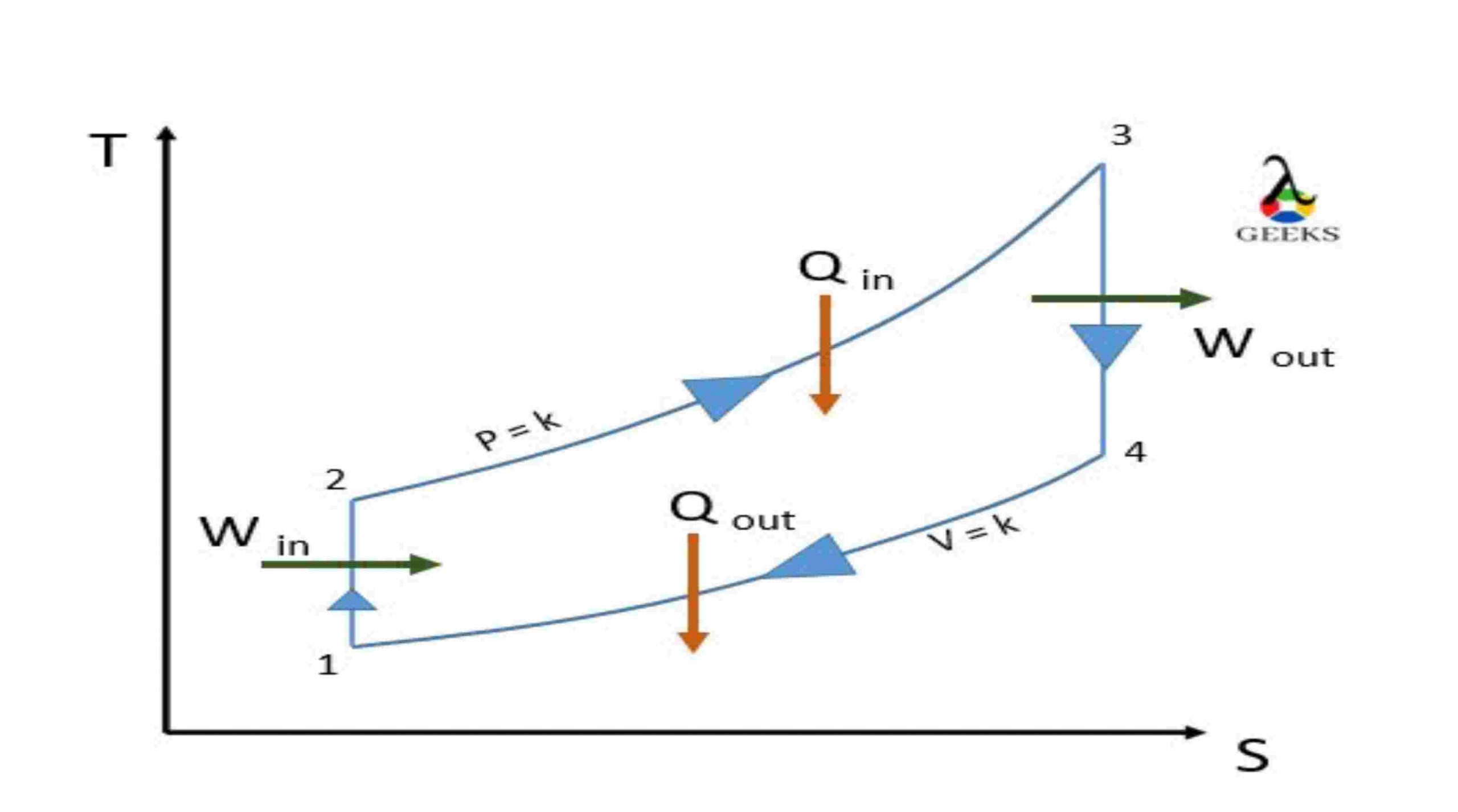
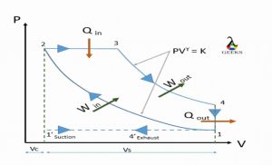
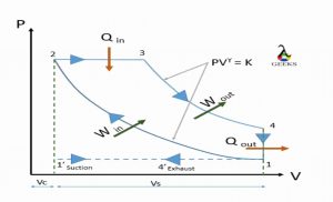
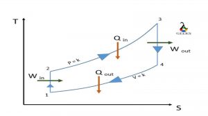
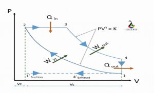
Diesel cycle pv diagram | diesel cycle ts | diesel cycle pv and ts diagram | diesel cycle pv ts diagram | diesel cycle diagram

Diesel cycle
PV daigram
TS daigram
TS daigram

Processes:

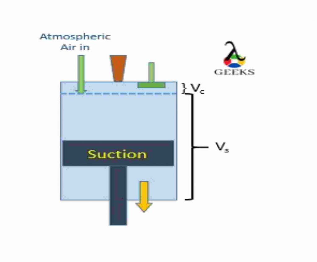
1’- 1: suction of Atmospheric air

Atmospheric air is sucked into the cylinder to carry out the compression process. when piston travel in downward direction towards Bottom Dead Center.

system acts as open system.

1-2: Isentropic Adiabatic compression

The piston travels from Bottom of the cylinder (BDC) to Top of the cylinder (TDC), compressing the air adiabatically, keeping entropy constant. No heat heat interaction is taken under consideration. System acts as a closed system.

2-3: Constant pressure heat addition

just before end of compression stroke, fuel is injected with the help of a fuel manifold, and this mixture of fuel with high temperature and high-pressure air makes the fuel to self-ignite (Unlike the petrol engine, Diesel engine doesn’t have spark plug to help combustion process, it has fuel injector is placed to insert the fuel) and releasing the heat in high amount, causing the force at the head of the piston making it move to BDC. This process is carried out under constant pressure. (Actual process is not possible under constant pressure). At a point it acts as a open system as fuel enters the system.

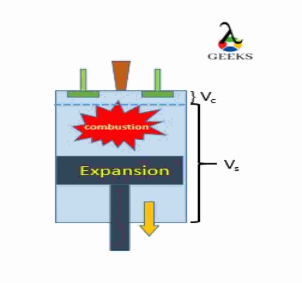
3-4: Isentropic Adiabatic expansion

The piston travels from Top of the cylinder (TDC) to Bottom of the cylinder (BDC) due to the force result of the combustion. And expansion takes place at constant entropy. No heat interaction is taken under consideration.

system acts as a closed system.

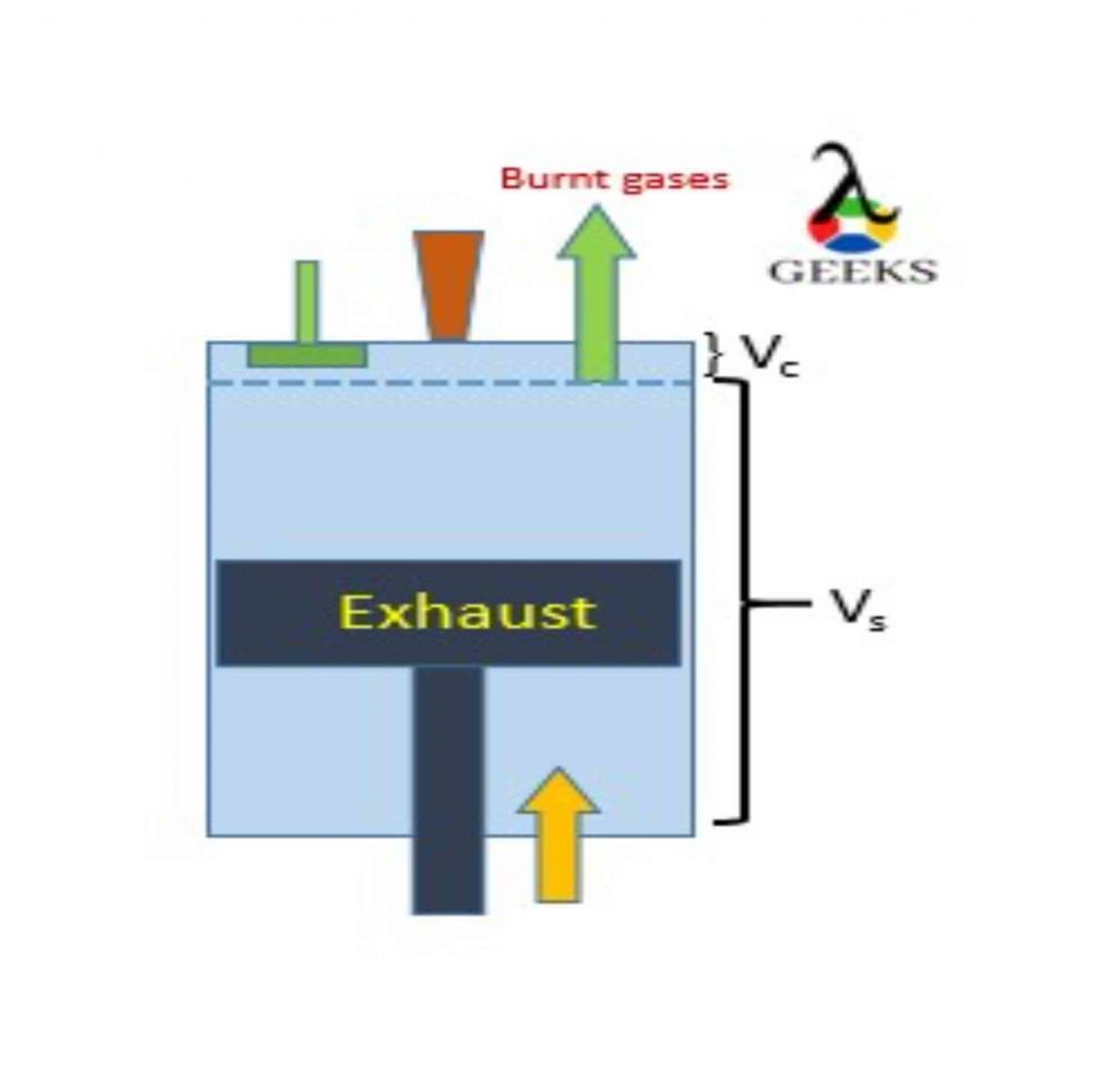
4-1-4’: Exhaust of burnt gases

The burnt gas is let out from the exhaust port to make a start for the next cycle. system again acts a open system. we assume the exhaustion process take place at constant volume.

Diesel cycle analysis

1. The piston in the reciprocating engine moves from Top Dead Center to Bottom Dead Center, causing low pressure inside the cylinder. At this point, the inlet port is let open allowing fresh atmospheric oxygen-rich air to enter into the cylinder. The reciprocating system acts as the open system while this process, allowing mass to enter the system.

this process is carried out at a constant pressure (1′-1)

At the end of the suction, the port is closed, and the the system acts as a closed system.

1 1

2. The ideal cycle process start when the piston reaches the Bottom Dead Center and starts moving towards Top dead Center.

The reciprocating engine plays as a closed-system. The air inside the cylinder is compressed by the piston. the compression is isentropic-adiabatic compression. (No entropy generation and no heat consideration). As a result of compression, the air reaches high pressure and high temperature.

Before the piston reaches the Top of the cylinder (TDC), the fuel is through the manifold in to the cylinder.

This introduced fuel is in spray form; as the fuel comes in contact with the high pressure and high-temperature environment, it gets self-ignited (No need of spark-plug), causing energy release (Chemical energy is transformed into heat energy).

2.1 1
2.2 2

3. The actual power generation takes place at this process; the high force is generated when the combustion takes place, and it forces the piston from Top Dead Center to Bottom Dead Center. The expansion process takes place at this point.

The force is transmitted to run the crankshaft and generate the mechanical energy from the heat energy.

(This stroke is also known as power stroke, in four stroke engine we get one power stroke for every two rotation while in Two stroke we get power power stroke for each rotation.)

3

4. Burnt gas (residue) must be let out of the cylinder, hence that work is done by piston by
moving from BDC to TDC

And the one cycle of is completed.

(If reciprocating engine is four stroke each operation take place separately, while for two stoke two operations are performed simultaneously. )

4

Diesel cycle derivation| diesel cycle formula

Heat Rejected:

heat\\ rejected.\\ Q_{2}=\\ Q_{4-1} =\\ m\\ Cv\\ (T_4-T_1)

Work output:

W_{net}=Q_{net}= Q_1-Q_2

W_{net}= Q_{2-3} -Q_{4-1}

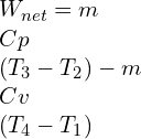
W_{net}=m\\ Cp\\ (T_3-T_2)-m\\ Cv\\ (T_4-T_1)

Compression ratio

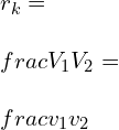
r_{k}=\\ \\frac{V_1}{V_2}=\\ \\frac{v_1}{v_2}

Expansion Ratio

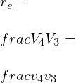
r_{e}=\\ \\frac{V_4}{V_3}=\\ \\frac{v_4}{v_3}

Cut-off ratio:

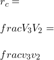
r_{c}=\\ \\frac{V_3}{V_2}=\\ \\frac{v_3}{v_2}

we can corelate the above equation in form as below:

Compression ration can be define as product of expansion ration and cut-off ratio.

r_{k}=\\ r_e\\times r_c

Let us see derivation of each individual process:

Process 3-4:

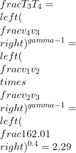
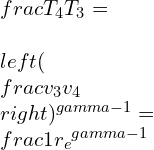
\\frac{T_4}{T_3}=\\ \\left ( \\frac{v_3}{v_4} \\right )^{\\gamma -1}=\\frac{1}{{r_e}^{\\gamma -1}}

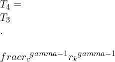
T_4=\\ T_3\\ .\\ \\frac{{r_c}^{\\gamma -1}}{{r_k}^{\\gamma -1}}

Process 2-3:

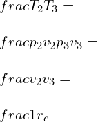
\\frac{T_2}{T_3} =\\ \\frac{p_2 v_2}{p_3v_{3}}=\\ \\frac{v_2}{v_3}=\\ \\frac{1}{r_c}

T_2=\\ T_3\\ .\\ \\frac{1}{r_c}

Process 1-2:

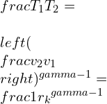
\\frac{T_1}{T_2}=\\ \\left ( \\frac{v_2}{v_1} \\right )^{\\gamma -1}=\\frac{1}{{r_k}^{\\gamma -1}}

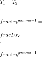
T_1=T_2\\ .\\ \\frac{1}{{r_k}^{\\gamma -1}}=\\ \\frac{T_3}{r_c}\\ .\\ \\frac{1}{{r_k}^{\\gamma -1}}

we will further use this temperature values to get efficiency equation.

The efficiency of diesel cycle derivation | diesel cycle efficiency | diesel cycle efficiency derivation | air standard efficiency of diesel cycle | diesel cycle efficiency formula | derivation of diesel cycle efficiency | thermal efficiency of diesel cycle

Efficiency

Efficiency=\\ \\frac{Work\\ output}{Work\\ input}

\\eta =\\ \\frac{W_{net}}{Q_{in}}

\\eta =\\ \\frac{Q_1-Q_2}{Q_{1}}

\\eta =\\1- \\frac{Q_2}{Q_{1}}

\\eta =\\1- \\frac{m\\ Cv\\ (T_4-T_1))}{m\\ Cp\\ (T_3-T_2)}

\\eta =\\1- \\frac{T_4-T_1}{\\gamma \\ (T_3-T_2)}

By substituting  T1,T2,T3 in eff enq

\\eta =\\ 1\\ -\\ \\frac{T_3.\\frac{{r_c}^{\\gamma -1}}{{r_k}^{\\gamma -1}}.\\frac{T_3}{r_c}\\frac{1}{{r_k}^{\\gamma -1}}}{\\gamma \\left ( T_3-T_3\\ . \\frac{1}{r_c}\\right )}

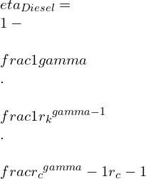
\\eta _{Diesel}=\\ 1-\\ \\frac{1}{\\gamma }\\ .\\ \\frac{1}{{r_k}^{\\gamma -1}}\\ .\\ \\frac{{r_c}^{\\gamma }-1}{{r_c}-1}

Compression ratio of diesel cycle

The compression ratio of the diesel cycle is the ratio of the maximum volume available in the cylinder when the piston is at Bottom Dead Center-(BDC) to the minimum volume available when the piston is at TDC.

Compression\\ ratio= \\frac{Total\\ volume}{clearance\\ volume}

r_{k}=\\ \\frac{V_1}{V_2}=\\ \\frac{v_1}{v_2}

Mean effective pressure formula for diesel cycle

Mean effective pressure is the ratio of network-done to the swept-volume

MEP = \\frac{net work-output}{Swept\\ volume}

MEP = \\frac{m\\ Cp\\ (T_3-T_2)-m\\ Cv\\ (T_4-T_1)}{v_1-v_2}

Cut off ratio in diesel cycle

The cut-off ratio in the diesel cycle is defined as the ratio of volume after combustion to the volume before combustion.

Cut-off\\ ratio= \\frac{Compression\\ ratio}{Expansion\\ ratio}

r_{c}=\\ \\frac{V_3}{V_2}=\\ \\frac{v_3}{v_2}

Semi diesel cycle

Semi diesel cycle, also known as the dual cycle, is the combination of otto and diesel cycles.

In this semi diesel/ dual cycle the heat is added at both constant volume and constants pressure.

( there is simple modification only, the part of heat added is under the constant volume and a remaining part of heat is added at constant pressure)

dual pv 2
P-V diagram

process:

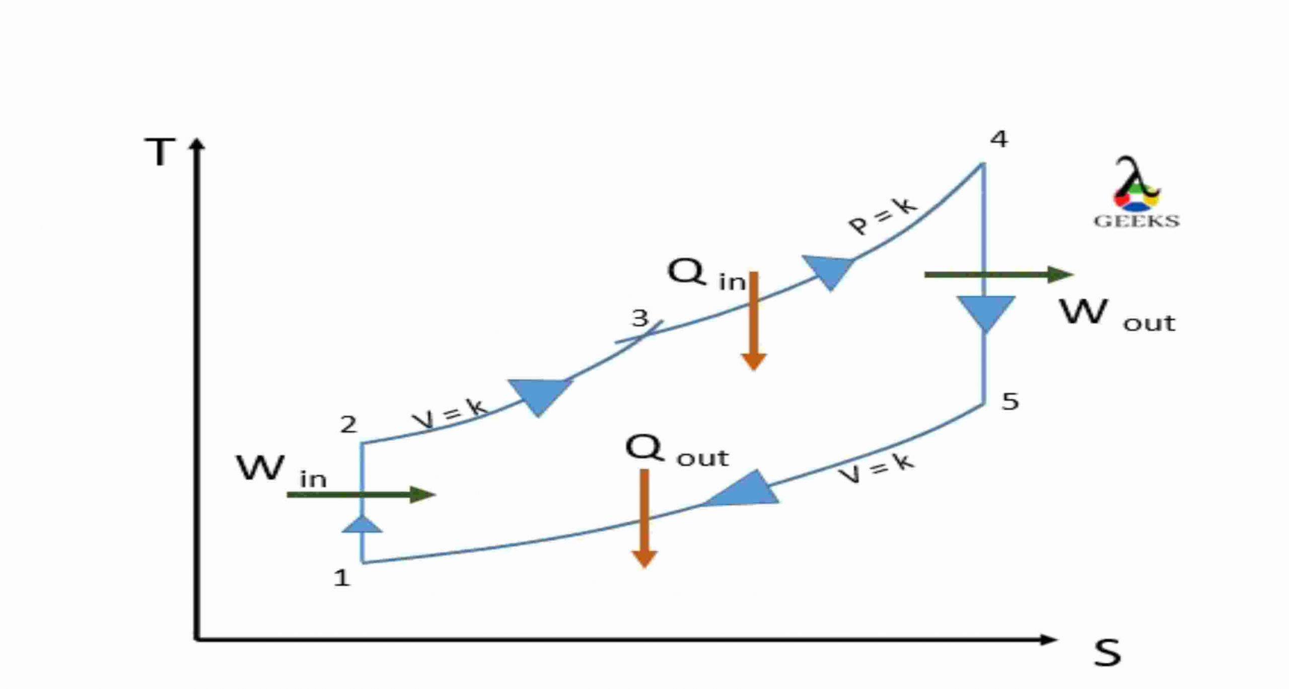
Dual Ts 2
T-S diagram

1-2: Isentropic Adiabatic compression:

Air is compressed adiabatically, keep entropy constant and no heat interaction.

2-3: Constant volume Heat addition:

just before the end of compression stroke , that is piston reaches the TDC of cylinder, the fuel is
added and combustion take place at a Isochoric condition, (constant volume).

3-4: Constant pressure Heat addition

A part of combustion is also carried at at constant pressure. and with this heat addition is completed.

4-5: Isentropic Adiabatic expansion

Now, as the high amount of force is generated it pushes piston now and causes the power stroke.

The work output is obtain at this point.

5-6: Constant volume Heat rejection

At the end the burnt gas is let out of the system to make place for fresh supply of air and carry out next cycle.

Two cycle diesel

A two-cycle diesel engine, also known as a two-stroke diesel engine, works similarly to a four-stroke diesel engine. But it gives power stroke for each revolution while a four-stroke engine gives power stroke for two revolutions.

There exists a transfer port inside the cylinder to carry two operations simultaneously.

When the compression takes place, the suction is also taking place.

And when expansion takes place, the input of oxygen-rich air takes place, letting exhaust burn gas out

Simultaneously.

Difference between diesel and otto cycle| diesel vs otto cycle

ParametersDiesel cycleOtto cycle
DefineThe diesel cycle or Ideal diesel cycle is the power-producing cycle where heat addition takes place at constant pressure.The Otto cycle is also the ideal power-generating cycle, where heat addition takes place at Isochoric condition (constant volume.)
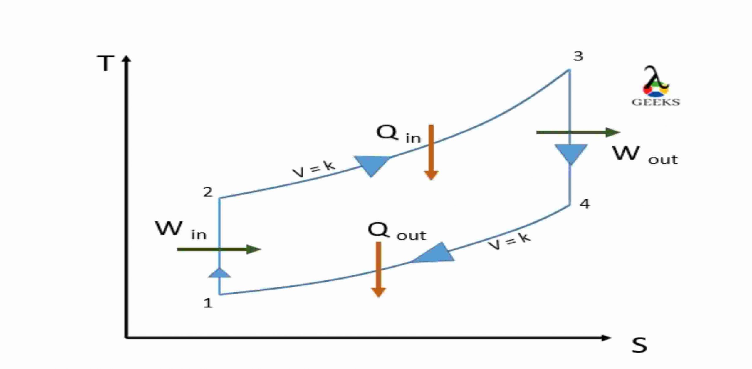
T-S diagramTS 1 scaledotto scaled
ProcessTwo isentropic ( 1-2 & 3-4 )
One isobaric heat addition (2-3)
One isochoric heat rejection (4-1)
Two isentropic ( 1-2 & 3-4 )
one isochoric heat addition (2-3)
one isochoric heat rejection (4-1)
Compression ratioThe efficiency of diesel cycle is more as compare to Otto cycle..The efficiency of diesel cycle is less as compare to Otto cycle.
Same compression ratioThe efficiency of diesel cycle is less as compare to Otto cycle.The efficiency of diesel cycle is more as compare to Otto cycle.
Same maximum pressureThe efficiency of diesel cycle is less as compare to Otto cycle.The efficiency of diesel cycle is more as compare to Otto cycle.
ApplicationDiesel cycle is used for Diesel/IC engineOtto cycle is used for Petrol/SI engine

difference between otto cycle diesel cycle and dual cycle

ParametersDiesel cycleOtto cycleDual Cycle
DefineThe diesel cycle or Ideal diesel cycle is the power-producing cycle where heat addition takes place at constant pressure.The Otto cycle is also the ideal power-generating cycle, where heat addition takes place at Isochoric condition (constant volume.)The dual cycle or semi diesel cycle is a combination of the Otto and diesel cycles. In this cycle, the heat is added at both Isochoric condition (constant volume) and isobaric condition (constants pressure.)
T-S diagramTS 1 scaledotto scaledDual Ts scaled
ProcessTwo isentropic (1-2&3-4 )
One isobaric heat addition (2-3)
One isochoric heat rejection (4-1)
Two isentropic (1-2 & 3-4 ) one isochoric heat addition (2-3)
one isochoric heat rejection ( 4-1)
Two isentropic ( 1-2 & 4-5 )
One isochoric heat addition(2-3)
One isobaric heat addition (3-4)
One isochoric heat rejection (4-1)
Compression ratioCompression ratio is 15-20Compression ratio is 8-10Compression ratio is 14
Same compression ratioThe Efficiency of diesel cycle is more as compare to The Otto cycle.The Efficiency of diesel cycle is less as compare to The Otto cycle.The efficiency is between
both the cycles (i.e Otto and
Diesel)
Same maximum pressureThe Efficiency of diesel cycle is less as compare to The Otto cycle.The Efficiency of diesel cycle is more as compare to The Otto cycle.The efficiency is between
both the cycles (i.e Otto and
Diesel)
ApplicationDiesel cycle is used for Diesel/IC engineOtto cycle is used for Petrol/SI engineDual cycle is used for IC engine.

Application of diesel cycle

Diesel-Internal Combustion engines:

  • Automobiles Engines
  • Ships and marine applications
  • Transport vehicles.
  • machinery used for agriculture
  • construction equipment and machines
  • military and defense
  • HVAC
  • Power generation

Advantages of diesel engine

New advanced have made diesel engine performance quite good, it is less noisy and has low maintenance cost.

Diesel engine are reliable and robust.

No need of spark-plug , fuel used is of self-igniting nature.

fuel cost is also low as compare to petrol.

diesel cycle sample problems | diesel cycle example | diesel cycle example problems

Q1.With compression ratio of 14, and cut-off at 6% what will be the efficiency of the diesel cycle?

Ans=

Pv 3

r_k=\\frac{v_1}{v_2}=14

v_3-v_2=0.06(v_1-v_2)

v_3-v_2=0.06(14v_2-v_2)

v_3-v_2=0.78v_2

v_3=1.78v_2

Cut-off ratio, r_c=\\frac{v_3}{v_2}=1.78

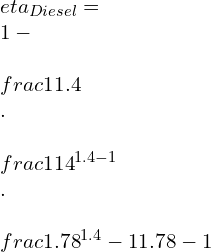
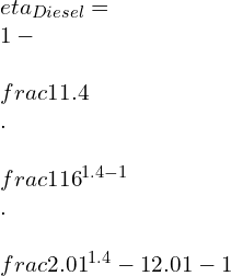
\\eta _{Diesel}=\\ 1-\\ \\frac{1}{\\gamma }\\ .\\ \\frac{1}{{r_k}^{\\gamma -1}}\\ .\\ \\frac{{r_c}^{\\gamma }-1}{{r_c}-1}

\\eta _{Diesel}=\\ 1-\\ \\frac{1}{1.4}\\ .\\ \\frac{1}{{14}^{\\1.4 -1}}\\ .\\ \\frac{{1.78}^{1.4 }-1}{{1.78}-1}

\\eta _{Diesel}=\\ 1-0.248.\\frac{1.24}{0.78}=0.605

\\eta _{Diesel}=60.5%

Q2. Standard diesel cycle with compression ratio of 16, Heat is added at constant pressure of 0.1 MPa. Compression begins at 15 deg Celsius and reaches 1480 deg Celsius at end of combustion.

Find the following:

1. Cut-off ratio

2. Heat added/kg of air

3. Efficiency

4. MEP

Ans=

r_k=\\frac{v_1}{v_2}=16

T1= 273 + 15 = 288K


p1= 0.1 MPa = 100 KN/m2


T3 = 1480 + 273 = 1735K

Pv 4
TS 2

\\frac{T_2}{T_1}= \\left ( \\frac{v_1}{v_2} \\right )^{\\gamma -1}=(16)^{0.4}=3.03

T_2= 288 \\times 3.03= 873K

\\frac{p_2v_2}{T_2}=\\frac{p_3v_3}{T_3}

(a) Cut-off ratio:
r_c=\\frac{v_3}{v_2}=\\frac{T_3}{T_2}=\\frac{1753}{273}=2.01

(b) Heat Supplied:
Q_1=Cp\\ (T_3-T_2)

Q_1=1.005\\ (1753-873)

Q_1=884.4 kJ/kg

\\frac{T_3}{T_4}=\\left ( \\frac{v_4}{v_3} \\right )^{\\gamma -1}=\\left ( \\frac{v_1}{v_2}\\times \\frac{v_2}{v_3} \\right )^{\\gamma -1}=\\left ( \\frac{16}{2.01} \\right )^{0.4}=2.29

T_4=\\frac{1753}{2.29}=766\\ K

heat rjected,

Q_2=Cv\\ (T_4-T_1)

Q_2=0.718\\ (766-288)=343.2kJ/kg

(c) Cycle Efficiency = 1-\\frac{Q_2}{Q_1}

\\eta =1-\\frac{343.2}{884.4}=0.612=61.2%

Also can be determined by;

\\eta _{Diesel}=\\ 1-\\ \\frac{1}{\\gamma }\\ .\\ \\frac{1}{{r_k}^{\\gamma -1}}\\ .\\ \\frac{{r_c}^{\\gamma }-1}{{r_c}-1}

\\eta _{Diesel}=\\ 1-\\ \\frac{1}{1.4}\\ .\\ \\frac{1}{{16}^{1.4 -1}}\\ .\\ \\frac{{2.01}^{1.4 }-1}{{2.01}-1}

\\eta _{Diesel}=1-\\frac{1}{1.4}.\\frac{1}{3.03}.1.64

\\eta _{Diesel}=0.612= 61.2%

W_{net}=Q_1\\times \\eta _{cycle}

W_{net}=884.4\\times 0.612\\times = 541.3 kJ/kg

v_1=\\frac{RT_1}{p_1}=\\frac{0.287\\times 288}{100}=0.827m^{3}/kg

v_2=\\frac{0.827}{16}=0.052\\ m^3/kg

\\therefore\\ v_1-v_2=0.827-0.052=0.775\\ m^3/kg

(d) mean effective pressure (MEP):

MEP=\\frac{W_{net}}{v_1-v_2}=\\frac{541.3}{0.775}=698.45 kPa

FAQs

Otto cycle vs. diesel cycle efficiency

At the same compression ratio: efficiency of diesel cycle is more as compare to Otto cycle.
At same maximum pressure: efficiency of diesel cycle is less more as compare to Otto cycle.

Diesel cycle chart

1’- 1: suction of Atmospheric air

1-2: Adiabatic compression

2-3: Constant pressure heat addition (fuel injection & combustion)

3-4: Adiabatic expansion

4-1-4’: Exhaust of burnt gases

Pv 2

When the efficiency of diesel cycle approaches the Otto cycle efficiency

The efficiency of the diesel cycle approaches the Otto cycle efficiency when the cut-off ratio approaches zero.

Why are engines that use the Diesel cycle able to produce more torque than engines using the Otto cycle

The diesel engine has a greater compression ratio than the Otto cycle engine.

Combustion in the diesel cycle takes place at TDC at the end of the compression stroke and causes the piston to move downward. While in the Otto cycle, engine combustion takes place when the piston is slightly moving towards BDC and contributes to acquire speed.

Diesel fuel is more dense than petrol (used in the Otto cycle), which generates more energy in terms of power.

Also, the size factor does matter; the stroke length and Bore diameter of the Diesel engine is greater than the Otto cycle engine.

Why cant petrol be used in a diesel cycle.

The volatility of petrol is much higher than Diesel; even before completion of the compression stroke, the high pressure will evaporate the fuel.

Hence petrol will ignite in the uncontrolled matter, causing detonation and misfiring.

it will result in damaging of the cylinder hence one should never start the engine if such incidence take place. It is advisable to contact the concern person to remove the petrol form the engine.

Why is the diesel cycle only applicable to large low-speed engines

Diesel cycle uses fuel which is more viscous and power produce in terms of the torques is more.

when we need application of high load we cant use petrol engine as the efficiency will be less for loading condition and will use more fuel.

hence the diesel engine will be beneficial here where the power produce is more at low speed.

for more article related to Mechanical Engineering visit our website.

9 Facts On Current Divider Circuit & Current Division

current divider

What is current and voltage division?

Voltage and current divider

Current and voltage division are real-life examples of Kirchhoff’s laws. The current division takes place in a parallel circuit, while voltage division occurs in a series circuit.

What are the current divider rule and voltage divider rule?

Current divider rule | Current divider law

What is a current divider?

The current-divider rule is a practical application of Kirchhoff’s current law. It states that,

In a circuit with a parallel combination of resistors, the current gets divided into all the branches having the same voltage across them. Thus a parallel circuit behaves as a current divider.

What is Voltage divider with current source ?

Voltage divider current

A voltage divider with a current source divides the supply voltage in the resistances. The voltagedrop across any resistor is the multiplication of the resistances with the value of current in the circuitry.

Current divider circuit example

Current divider circuit
image1

Let us take a circuit with a DC voltage source of V volt and two resistors R1 and R2, connected in parallel. The total current in the circuit is i,  current through R1 is i1, and R2 is i2.

What is Current divider theory | Current divider rule definition | Current divider definition ?

Current divider theorem | Current divider principle

The current-divider rule says that the current in any branch of the parallel circuit is equal to the total current in the circuit multiplied by the ratio of the resistance of the opposite branch and the total circuit resistance.

Current divider rule derivation | Formula derivation

Current divider parallel

In the image1, we can see two parallelly connected resistances R1 and R2, are joined with a DC voltage V and currents thru them are i1 and i2, respectively.

The equivalent resistance of the circuit is

{\\displaystyle I_{X}={\\frac {R_{T}}{R_{X}+R_{T}}}I_{T}\\ }
{\\displaystyle {\\frac {1}{R_{T}}}={\\frac {1}{R_{1}}}+{\\frac {1}{R_{2}}}+\\ldots +{\\frac {1}{R_{n}}}}
I_{X}={\\frac {Y_{X}}{Y_{Total}}}I_{T}
I_{X}={\\frac {Y_{X}}{Y_{Total}}}I_{T}={\\frac {\\frac {1}{R_{X}}}{{\\frac {1}{R_{X}}}+{\\frac {1}{R_{1}}}+{\\frac {1}{R_{2}}}+{\\frac {1}{R_{3}}}}}I_{T}

I_{R}={\\frac {\\frac {1}{j\\omega C}}{R+{\\frac {1}{j\\omega C}}}}I_{T}=11 ={\\frac {1}{1+j\\omega CR}}I_{T}\\ ,

What is Voltage and current divider formula ?

Current divider rule formula

According to the currentdivider rule,

Current in through any resistor = Total current of the network x resistance of other resistor/equivalent resistance of the circuit.

Voltage divider rule

According to the voltage divider rule,

The voltage drop across any resistor = Total current of the network x resistance of that resistor

Current divider equation | Derive current divider equation

For the above circuit, we can see that resistances R1, R2, R3, and RX are connected in parallel. A voltage source is added to this combination, and current IT flows through the circuit. The equivalent resistance of R1, R2, and R3 is denoted as RT, and If the current across resistor RX is IX, we can say that,

i_{L}={\\frac {R_{out}}{R_{out}+R_{L}}}A_{i}i_{i}\\ .

What is Current divider rule for 2 resistors in parallelly connected ?

Parallel circuit current divider | Current divider formula for parallel circuit

Two resistors R1 and R2, are connected in parallel with a DC source V. If the currents i1 and i2 flow through them and the total current is I then,

{\\displaystyle I_{X}={\\frac {R_{T}}{R_{X}+R_{T}}}I_{T}\\ }
{\\displaystyle {\\frac {1}{R_{T}}}={\\frac {1}{R_{1}}}+{\\frac {1}{R_{2}}}+\\ldots +{\\frac {1}{R_{n}}}}

What is the Current divider rule for 3 resistors in parallelly ?

Current divider rule for 3 resistors

Three resistors R1, R2, and R3, are connected in parallel with a voltage source V. Total current in the circuit is IT and branch currents are i1, i2, and i3, respectively. Therefore,

{\\displaystyle {\\frac {1}{R_{T}}}={\\frac {1}{R_{1}}}+{\\frac {1}{R_{2}}}+\\ldots +{\\frac {1}{R_{n}}}}
I_{X}={\\frac {Y_{X}}{Y_{Total}}}I_{T}={\\frac {\\frac {1}{R_{X}}}{{\\frac {1}{R_{X}}}+{\\frac {1}{R_{1}}}+{\\frac {1}{R_{2}}}+{\\frac {1}{R_{3}}}}}I_{T}

Current in a voltage divider

As the voltage dividers are series circuits, the current through all the resistors or impedance elements is the same. With the help of the total current, the voltage divider rule is constructed. The voltage drop across any resistor equals the total current multiplied by the resistance of that resistor present in the circuitry.

Current divider applications | Current divider examples

  • The main purpose of using a current division is to reduce complexity while solving for current in any circuit. It divides the current into small components.
  • Current division is used to protect circuits from overheating. As it divides the total current into fractions, small current components generate, and large current flow is avoided. This allows less heat dissipation and saves the circuits from any damage.

High current voltage divider

A voltage divider that can deliver a high amount of current is difficult to be built with a traditional resistor network. A switching regulator or a buck converter type design can come in handy in this case. For the buck converter approach, its voltage reference can be replaced with a divider derived from the incoming supply.

Series voltage divider with parallel load current

If a load resistance is connected with the voltage divider in parallel, the overall equivalent resistance decreases. Therefore the current in the circuit increases, but the voltage at the divider output drops.

AC current divider

AC circuits function the same as DC. Just the impedances must be written with their phasor representations using the complex quantity j.

Current divider impedance

If we generalize the resistive network equation for elements other than resistance,

{\\displaystyle {\\begin{aligned}V&=|V|e^{j(\\omega t+\\phi _{V})},\\\\I&=|I|e^{j(\\omega t+\\phi _{I})}.\\end{aligned}}}
{\\displaystyle Z={\\frac {V}{I}}={\\frac {|V|}{|I|}}e^{j(\\phi _{V}-\\phi _{I})}.}
{\\displaystyle {\\begin{aligned}|V|&=|I||Z|,\\\\\\phi _{V}&=\\phi _{I}+\\theta .\\end{aligned}}}

Where IT is the total current, IX is the current through a particular branch, ZT is the equivalent impedance of the circuit, and ZX is the impedance of that branch.

To know about Inductors in Series and Parallel click here

How to use the current divider rule? How to apply the current divider rule? | How to divide current in a parallel circuit?

Current divider method

The current division is calculated in the following steps:

  • First, find the equivalent resistance RT of the other circuit elements, excluding the one for which current needs to be calculated (RX)
  • Compute the fraction of this RT and RT + RX
  • Multiplying this quantity with the total current would fetch the desired branch current IX.

What is the difference between voltage divider and current divider ?

Voltage divider and current divider | Current divider vs voltage divider

Current DividerVoltage Divider
It is constructed through parallel circuits.It is constructed through series circuits.
The values of current through the resistors are measured.The values of voltage drop through the resistors are measured.
The voltages in all the resistors are equal, the currents vary.The currents in all the resistors are equal, the voltages vary.

Low current voltage divider

Voltage divider circuits with low or almost zero current can be used to design switches with an additional transistor.

Voltage divider current limit

There’s no specific limit for current in a voltage divider. However, observed values suggest that currents over 1 amp can be regarded as high for the voltage dividers.

Current divider problems with solutions

Current and voltage divider

Q. Two impedances, Z1 = 2+j5 and Z2 = 5+j2, are connected in a parallel circuit. Total current, I = 10 amp. Using the current division, find out the currents through individual impedances.

We know,

i_{L}={\\frac {R_{out}}{R_{out}+R_{L}}}A_{i}i_{i}\\ .

Therefore, I1 = 10 x (5+j2)/ 2+j5+5+j2 = 5(7-j3)/7 amp

I2 = I – I1 = 10 – 5(7-j3)/7 = 5(7+j3)/7 amp

Current and voltage divider examples | current and voltage divider problems

Q. Three resistors of 6 ohm, 12 ohm, and 18 ohm are connected in series with DC supply voltage 54V, then calculate the voltage drop across all the resistors.

The voltage divider rule says that voltage drop across any resistor in a series circuit = resistance of that resistor x the current.

Now, equivalent resistance of the circuit = 6 + 12 + 18 = 36 ohm

So, net current in the circuit = 54/36 = 1.5 A

Therefore, voltage drop across 6 ohm resistor = 1.5 x 6 = 9 Volt

voltage drop across 12 ohm resistor = 1.5 x 12 = 18 Volt

voltage drop across 18 ohm resistor = 1.5 x 18 = 27 Volt

Current divider rule example problems | Current divider sample problems

Q. 4 resistors with resistances 5 ohm, 10 ohm, 15 ohm, and 20 ohm are connected in parallel with a voltage source. The total current in the circuit is 5A, then compute the current thru the 10Ω resistor.

The equivalent resistance of the circuit = 5 x 10 x 15 x 20 / (50 + 75 + 100 + 150 + 200 + 300) = 17.14 Ohm

Therefore, current through the 10 ohm resistor = 5 x 17.14/10 = 8.57 A

Q. Two resistors of 10 ohm and 20 ohm are connected in parallel with a 200 V DC supply, then compute current thru the 20Ω resistor.

Net resistance in the circuit = 10 x 20/ 30 = 20/3 ohm

Total current in the circuit = 200/(20/3) = 30 A

So the current through 20 ohm resistor = (20/3)/20 x 30 = 10 A

Q. For the network with n resistances shown below, R1 = R2 = R3 = ………= Rn = R. Find the current passing through Rn.

current divider problem

Equivalent resistance of the circuit,

{\\frac {1}{Z_{\\text{eq}}}}={\\frac {1}{Z_{1}}}+{\\frac {1}{Z_{2}}}+\\cdots +{\\frac {1}{Z_{n}}}

We know the total current in the circuit is I

Therefore, current through Rn = (R/n)/R x I = I/n

Frequently Asked Questions | Short Notes | FAQs

Q. How can we calculate the current division?

Current division occurs in a parallel circuit. The supply current gets divided into branches connected in parallel. The voltage across all the branch resistors is equal to voltage supplied. With the help of Ohm’s law and Kirchhoff’s current law, the current division is calculated. The divided current in one branch is the multiplication of the total current and the ratio of the other branch’s resistance with the sum of all the resistance.

Q. In which condition is the current divider rule applicable?

The currentdivider rule is applicable for any circuit where resistance or other impedance parameters are connected in parallel.

Q. What is the advantage of applying the current-divider rule in a parallel circuitry ?

The basic reason for using the current-divider rule in parallel circuits is to make problem-solving easier. In a parallel circuit, the current gets divided into branches, So calculating current thru the branches becomes less time-consuming if the total current is known.

Q. Does the current division rule disobey Ohm’s law?

The Current-divider rule is based on Ohm’s law itself. The fundamental concept of Ohm’s law is used to calculate the divided currents.

Q. State the difference between a voltage divider and a current divider?

The main difference between a voltage divider and a current-divider is the operating circuit. The Voltage divider rule is applied in series circuits where as the current-divider rule is utilized in parallel circuit.

Q. When can we apply the voltage divider and the current divider rule?

In a series circuit, the voltage divider rule is used to calculate the voltage drop across the resistors. In a parallel circuit, the current-divider rule is used to calculate the branch currents.

Q. What are the voltage dividers?

The voltage dividers are linear circuits where the output voltage is obtained from the fraction of input voltage. The most common example of voltage is a potentiometer.

Q. How to use a rheostat so that it works as a potential divider and current limiter?

A rheostat can be used as a large variable resistor. It has three terminals, two at the ends and one movable contact. By adding voltage sources at the ending terminals, the voltage across the other terminal is obtained. This way the rheostat works as a potential divider, and the terminals work as current limiters.

Q. What are the advantages of a voltage divider?

A voltage divider helps in getting the voltage drop across components from the large supply voltage.

Q. How can we calculate the value of current passing through the resistor R1 in the circuit?

The current through resistor R1 is the total current multiplied by the other resistance divided by the sum of all resistance in the circuit.

Q.Why cannot we use the voltage divider method to get a constant current?

The supply voltage keeps fluctuating in a circuit. So we cannot get a constant current.

Q. Three parallel branches with resistances are connected across a DC voltage. What would be the ratio of the branch currents I1, I2, and I3 if the branch resistance ratio is  R1: R2 : R3 = 2 : 4 : 6?

Let us assume that R1 = 2x ohm, R2 = 4x ohm and R3 = 6x ohm

Equivalent resistance of the circuit = 2x x 4x x 6x/ 8×2 + 24×2 + 12×2 = 12x/11 ohm

Therefore, I1 = I x 12x/11/(2x) = 6I/11 A

I2 = I x 12x/11/(4x) = 3I/11 A

I3 = I x 12x/11/(6x) = 2I/11 A

So I1 : I2 : I3 = 6:3:2

Q. Can we apply the voltage divider rule in an ac circuit?

Voltage divider rule is equally applicable for AC circuit calculations, but only if phasor representation is used involving the imaginary quantity ‘j’.

Q. How to obtain zero output voltage using a potential divider?

Zero output voltage can be achieved by keeping a potentiometer in series with a resistance. When this combination is subjected to supply voltage, an end terminal and the middle terminal of the potentiometer fetch output. When the slider terminal is at one end, the voltage is zero.

Q. In a series RC circuitry, the voltage across the capacitor and resistor are 60V & 80V, then What will be total voltage in the circuitry?

By simply applying voltage divider rule, the total voltage is the summation of the voltages across the resistors and the capacitors, So Total voltage = VR+VC=60+80=140V.

Q. Current flow is divided between the different branches in a __.

The answer would be parallel circuitry.

Q. Does a voltage divider affect current?

A voltage divider is nothing but a parallel circuit,will not affect the total current of the circuit. However, the branch current values differ according to the branch impedance.

Q. Is current divided in a parallel circuit?

By the rule of current division, we can say that the parallel circuits divide current flowing through them.

For more article click here.

Overall Heat Transfer Coefficient: 11 Important Facts

Capture 300x161 1

WHAT IS THE OVERALL HEAT TRANSFER COEFFICIENT?

In industry, heat transfer problems are usually resolved for composite materials or systems with different layers which involve different modes of heat transfer such as conduction, convection, and radiation. The thermal resistance that is offered by the different layers in a system is referred to as the Overall Heat Transfer Coefficient. It is also known as the U-factor.

The U-factor that is used in calculating overall heat transfer is analogous to the convection heat transfer coefficient used in Newton’s law of cooling. The overall heat transfer coefficient is dependant on the geometry of the object or surface. For example, in a wall, we can observe different modes of heat transfer, the outer surface of the wall experiences convection heat transfer while the space between the walls undergoes conduction mode of heat transfer.

The overall heat transfer coefficient of the wall is taken to be a sum of the convective heat transfer coefficient and the conductive heat transfer coefficient. In short, the overall heat transfer coefficient is the summation of the individual heat transfer coefficient. Further explanation on the derivation of the overall heat transfer coefficient and using it for composite heat transfer problems are explained below.

SIGNIFICANCE OF OVERALL HEAT TRANSFER COEFFICIENT

In industrial applications, it is essential to know the overall heat transfer coefficient, especially in cases where the heat transfer rate needs to be optimized for better performance of a system. To calculate the heat transfer rate Q(dot) for any system with different fluids or different layers, it is essential to know the overall heat transfer coefficient.

From the value of the overall heat transfer coefficient and the rate of heat transfer, it is possible to calculate the individual heat transfer coefficient. This would help in modifying a particular portion of the thermal system for better performance as per the requirements.

Under steady-state conditions, the rate of heat transfer from a fluid at bulk temperature T1 to solid at bulk temperature T2 over an incremental area dA  is given by the rate of heat transfer dQ(dot) i.e.

dQ(dot) = U*(T2 – T1)*A

Here the overall heat transfer coefficient is represented by the letter U.

FORMULA FOR OVERALL HEAT TRANSFER COEFFICIENT | HOW TO FIND OVERALL HEAT TRANSFER COEFFICIENT | OVERALL HEAT TRANSFER COEFFICIENT FORMULA | HOW TO CALCULATE OVERALL HEAT TRANSFER COEFFICIENT | OVERALL HEAT TRANSFER COEFFICIENT DERIVATION

The formula for the Overall Heat Transfer coefficient is given by

Qdot = U*(T1 + T2)*A

Derivation for the Overall Heat Transfer coefficient for Wall given below

Overall Heat Transfer coeffiicient

Consider a composite wall that is exposed to the external environment at temperature T1, and the conduction coefficient is noted to be H1. The ambient temperature inside the room is T2 and the convection coefficient is H2. Here the heat transfer is using conduction and convection. Either side of the wall experiences heat transfer using convection at different magnitudes.

The temperature inside the wall varies and is a value between T1 and T2 if there is no source of heat generation from within the wall. The conduction coefficient of the wall is taken to be K in this case unless the wall is made up of different layers which is the usual case. In real life scenario, the wall is made up of different layers such as plastering, bricks, cement, etc. In such cases, it is essential to take into consideration the thermal resistance offered by each layer of the wall.

The overall heat transfer coefficient for the above system is as given below:

1

And the rate of heat transfer Q(dot) = UAΔT

It is evident that U is not a thermophysical property and depends on the flow, velocity, and also on the material through which the heat transfer takes place.

OVERALL HEAT TRANSFER COEFFICIENT WITH FOULING

Fouling is a usual problem that is encountered in heat exchangers. It is an additional layer that is formed on the inner surface of the heat exchanger. Several factors contribute to the fouling of the surfaces of heat exchangers. The rate of heat transfer is reduced because of fouling which in turn affects the heat transfer efficiency.

The decrease in heat transfer efficiency is accounted for in calculations using the fouling factor. It is often referred to as the dirt factor. The fouling factor is dependent on the fluid on either side of the heat exchanger.

The overall heat transfer coefficient with fouling is given by

he fouling

In the above equation,

U represents the overall heat transfer coefficient

h0 is the heat transfer coefficient on the shell side

hi is the heat transfer coefficient on the tube side

Rdo is the fouling factor on the shell side

Rdi is the fouling factor on the tube side

OD is the outer diameter of the tube

ID is the inner diameter of the tube

A0 is the outer area of the tube

Ai is the inner area of the tube

Kw is the value of resistance offered by the tube wall

From the equation, it is evident that the value of the overall heat transfer coefficient decreases with an increase in either or both values of fouling factor (i.e., tube side or shell side). This decrease in the overall heat transfer coefficient will in turn reduce the rate of heat transfer.

OVERALL HEAT TRANSFER COEFFICIENT UNITS | OVERALL HEAT TRANSFER COEFFICIENT UNIT CONVERSION | OVERALL HEAT TRANSFER COEFFICIENT CONVERSION

The S.I. unit of overall heat transfer coefficient is W/m2 K. Another unit that is used for representing the overall heat transfer coefficient is Btu/(hr.ft2 0F).

The unit conversion from SI unit to English units is follows:

1 W/m2 K = = 0.1761 Btu/(hr.ft2 0F).)

EFFECT OF FLOW RATE ON OVERALL HEAT TRANSFER COEFFICIENT | OVERALL HEAT TRANSFER COEFFICIENT VS FLOW RATE

The flow rate has an impact on the overall heat transfer coefficient. It is noted that there is a 10% decrease in heat transfer coefficient when the mass flow rate increases by three times. This estimation of the heat transfer coefficient is based on the Dittus-Boelter correlation.

While keeping the area constant, it is observed that the heat transfer coefficient increases by increasing the mass flow rate. A 90% increase in heat transfer coefficient is expected by doubling the mass flow rate. With this increase, there is an expected increase of pressure drop which is proportional to the mass flow rate.

For cases where the velocity is constant, the pressure drop decreases and is inversely proportional to the mass flow rate. The positive aspects that are attained from a higher heat transfer coefficient are lost due to the increased pressure drop when the area is kept constant.

OVERALL COEFFICIENT OF HEAT TRANSFER TABLE

The table below provides the overall heat transfer coefficient for a few equipment that are very often used in the industry. The range is provided because the overall heat transfer coefficient is dependent on the fluid that is used in the equipment. For gases, the value of the heat transfer coefficient is very low and that of liquids is much higher.

EquipmentU (W/m2)
Heat Exchanger5-1500
Coolers5-1200
Heaters20-4000
Condensers200-1500
Air Cooled Heat Exchangers50-600
Table 1: Overall Coefficient of Heat Transfer for different Equipment

AVERAGE OVERALL HEAT TRANSFER COEFFICIENT

In heat transfer problems which consist of two different fluids which could be water and alcohol at two different temperatures, in such cases the average of the temperatures of the two fluids is used for solving the heat transfer problem which is termed as the average overall heat transfer coefficient.

Let’s take Q to be the heat flowing through the surface at an average temperature ΔTavg, and the area across which the heat transfer takes place is taken to be A. The average overall heat transfer coefficient for this heat flow is as given below

2

OVERALL HEAT TRANSFER COEFFICIENT BASED ON INSIDE AREA

For heat exchangers, the overall heat transfer coefficient can be based on either the inside area or on the outside area

When the overall heat transfer coefficient is calculated based on the inside area, the convection coefficient at the inside is taken to be 1/hi, while the conduction coefficient at the interface is taken to be 1/ln(r0/ri)/2πkL and the convection coefficient on the outer surface of the heat exchanger is taken to be 1/h0.

Therefore, the overall heat transfer coefficient based on the inside area is given as

in 1

When the overall heat transfer coefficient is calculated based on the outside area, the convection coefficient at the inside is taken to be 1/hi, while the conduction coefficient at the interface is taken to be 1/ln(r0/ri)/2πkL and the convection coefficient on the outer surface of the heat exchanger is taken to be 1/h0.

Therefore, the overall heat transfer coefficient based on the inside area is given as

out 1

The significant difference between the two-equation is in the area, when the overall heat transfer coefficient is based on the inside area, the inner area of the heat exchanger is used in the equation. While when the overall heat transfer coefficient is based on the outside area, the outer area is taken in the equation.

DIFFERENCE BETWEEN INDIVIDUAL AND OVERALL HEAT TRANSFER COEFFICIENT

When heat is flowing through a composite material, the thermal resistance offered by different layers of the material which can be due to heat conduction or convection is referred to as the overall heat transfer coefficient. The overall heat transfer coefficient is the summation of the individual heat transfer coefficient. The thermal resistance is analogous to the electrical resistance in a circuit. Here the heat transfer coefficient is dependent on the material in series or parallel arrangement.

It is of great interest to determine the individual heat transfer coefficient from the overall heat transfer coefficient. For example, for a heat exchanger, the overall heat transfer coefficient can be measured experimentally, from this overall coefficient, extracting the thermal resistance offered by the hot and cold fluid individually is the problem to be solved.

OVERALL HEAT TRANSFER COEFFICIENT PROBLEMS

Consider a wall of thickness 5cm is made of bricks which has a thermal conductivity K=20 W/m K. The inner surface of the wall is exposed to room temperature of 250C while the external surface is exposed to the hot atmospheric temperature of 400C. What is the overall heat transfer coefficient, given the convection coefficient of air 25 W/m2K?

From the above problem, we can conclude that the system is exposed to convection on either side of the wall and conduction heat transfer within the wall. The thermal conductivity of the wall is given to be 20W/mK while the convection coefficient of air is noted to be 25 W/m2K.

calc

= 12.12 W/m2K

FREQUENTLY ASKED INTERVIEW QUESTIONS AND ANSWERS

1. overall heat transfer coefficient equation heat exchanger

he fouling 2

2. overall heat transfer coefficient double pipe | double pipe heat exchanger overall heat transfer coefficient

1/U = Do/hi.Di + Do.ln(Do/Di)/2kt + 1/ho+ Ri.Do/Di + Ro

3. overall heat transfer coefficient formula for cylinder

The overall heat transfer coefficient for a cylinder is given by the formula below which experiences both conduction and convection mode of heat transfer

cylinder

4. overall heat transfer coefficient for evaporator

TypeU (W/m2K)
Natural circulation – steam flowing outside and highly viscous fluid flowing inside300-900
Natural circulation – steam flowing outside and low viscous fluid flowing inside600-1700
Forced circulation – steam flowing outside and liquid flowing inside900-3000
Table 2: Overall Heat Transfer Coefficient for Evaporators

5. Overall heat transfer coefficient shell and tube | overall heat transfer coefficient for shell and tube heat exchanger | how to calculate overall heat transfer coefficient for heat exchanger | How do you calculate the overall heat transfer coefficient of an evaporator?

The overall heat transfer coefficient for any heat exchanger can be calculated using the below equation the method used might vary. One can choose the LMTD method as well

he fouling 1

6. Graphite heat exchanger overall heat transfer coefficient

The overall heat transfer coefficient for heat exchangers which are molded graphite to graphite is about 1000W/m2K while the overall heat transfer coefficient for graphite to air is observed to be 12 W/m2K

7. Aluminium overall heat transfer coefficient

The overall heat transfer coefficient for aluminum is noted to be 200W/m2K

8. Air to air heat exchanger overall heat transfer coefficient

The overall heat transfer coefficient of air-to-air heat transfer coefficient is noted to be between 350 to 500 W/m2K.

9. Area of the heat exchanger from overall heat transfer coefficient

The area of a heat exchanger can be calculated from the overall heat transfer coefficient using the following formula

he area

10. In which heat exchange process the value of the overall heat transfer coefficient will be highest?

The overall heat transfer coefficient is the highest for tubular heat exchangers used for evaporation with steam flowing outside the tubes and liquid flowing inside. They are noted to have an overall heat transfer coefficient in the range between 900 to 3000 W/m2K.

11. Can the overall heat transfer coefficient be negative?

In cases where the reference temperature is taken as the adiabatic wall temperature, the overall heat transfer coefficient will be negative which indicates that the heat flux is in the opposite direction with a definite temperature gradient.

12. Does the overall heat transfer coefficient change with temperature?

Overall heat transfer coefficient is dependent on the temperature gradient; therefore, temperature changes can result in changes in a temperature gradient. So, yes overall heat transfer coefficient changes with temperature.

13. What is the overall heat transfer coefficient and its application?

The thermal resistance that is offered by the different layers in a system is referred to as the Overall Heat Transfer Coefficient. It is also known as the U-factor. It is used in extracting the individual heat transfer coefficient of the different layers of a system.

The overall heat transfer coefficient of a system can be measured but the individual heat transfer coefficient of a system is difficult to obtain. In such situations, the overall heat transfer coefficient along with the rate of heat transfer will help in determining the individual heat transfer coefficient

14. What are the factors affecting the overall heat transfer coefficient?

The factors affecting the overall heat transfer coefficient are thermophysical properties such as the density, viscosity, and thermal conductivity of the fluid. Further, it is affected by the geometry and area across which the heat transfer is taking place. The velocity of fluids affects the overall heat transfer coefficient to a large extend. In heat exchanges, the type of flow also has a significant impact on the overall heat transfer coefficient.

15. What is the overall heat transfer coefficient in round tubes? | overall heat transfer coefficient pipe

A fluid flowing through a round tube experiences convective heat transfer between the fluid flowing on the outside and the outer surface of the tube, and also between the fluid flowing in the inside and the inner surface of the tube. There is conduction heat transfer between the outer surface and inner surface of the tube. Hence the overall heat transfer coefficient is given as follow:

(1/UA) overall = (L/kA) inner + (1/hA) + (L/kA) outer

Where k is the thermal conductivity of the tube and h is the convective heat transfer coefficient

Click Here, for latest reads on Thermostatic Expansion Valve.

For more post on Mechanical, please follow us.

Carnot Cycle: 21 Important Facts You Should Know

1 1 300x200 1

CARNOT CYCLE

Nicolas Léonard Sadi-Carnot, a French mechanical engineer, Scientist, and physicist, introduced a heat engine known as the Carnot Engine in the book “Reflections on the Motive Power of Fire. It leads to being the foundation of the Second law of thermodynamics and entropy. Carnot’s contribution holds a remark which gave him the title of “Father of Thermodynamics.

Table of Content

Carnot cycle in thermodynamics | working principle of Carnot cycle | ideal Carnot cycle | Carnot cycle thermodynamics | Carnot cycle definition | Carnot cycle working principle | air standard Carnot cycle| Carnot cycle reversible.

Carnot cycle is the theoretical cycle that works under two thermal reservoirs (Th & Tc) undergoing compression and expansion simultaneously.

It consists of four reversible processes, of which two are isothermal, i.e., constant temperature followed alternately by two reversible adiabatic processes.

The working medium used in the Sadi-Carnot cycle is atmospheric air. 

Heat addition and Heat rejection are carried out at a constant temperature, but no phase change is considered.

Carnot cycle
Carnot cycle

Importance of Carnot Cycle

The invention of the Carnot cycle was a very big step in the history of thermodynamics. First, it gave theoretical working of heat engine used for the design of an actual heat engine. Then, reversing the cycle, we get refrigeration effect (mentioned below). 

Carnot cycle work between two thermal reservoirs (Th & Tc), and its efficiency depends only on this temperature and doesn’t depend on the fluid type. That is Carnot’s cycle efficiency is fluid independent.

Carnot cycle pv diagram | Carnot cycle ts diagram | pv and ts diagram of Carnot cycle | Carnot cycle pv ts | Carnot cycle graph | Carnot cycle pv diagram explained | Carnot cycle ts diagram explained

2 1 2
P-V Carnot
3 3
T-S Carnot

Process 1-2: Isothermal expansion

In this process, the air is expanded with constant temperature while gaining heat. 

That is, constant temperature heat addition takes place. 

Expansion => pressure ↑ => results Temperature ↓

Heat Addition => Temperature ↑

Hence Temperature remain constant 

Process 2-3: Reversible adiabatic expansion 

In this process, the air is expanded, keeping entropy constant and with no heat interaction. 

That is no change in entropy, and the system is insulated

We get work output in this process

Process 3-4: isothermal compression

In this process, the air is compressed with a constant temperature while losing heat.

That is, constant temperature heat rejection takes place.

Compression => pressure ↓ => results: Temperature ↑

Heat Addition => Temperature ↓

Hence Temperature remain constant 

Process 4-1: Reversible Adiabatic Compression

In this process, the air is compressed, keeping entropy constant and no heat interaction. 

That is no change in entropy, and the system is insulated

We supply work in this process

Carnot cycle consists of | Carnot cycle diagram | Carnot cycle steps | 4 stages of Carnot cycle | Carnot cycle work| isothermal expansion in Carnot cycle| Carnot cycle experiment

Process 1-2:

The expansion process is carried out where temperature Th is kept constant, and heat (Qh) is added to the system. The temperature is kept constant as follows: The rise in temperature due to heat addition is compensated by the decrease in temperature due to expansion. 

Hence the process carried out results as constant temperature as the start and end temperature of the process is same.

Isothermal expansion

Process 2-3:

As we can see, the process is reversible (change in internal energy = 0) Adiabatic (only work transfer, no heat involvement), the expansion carried out just results in a change in temperature (from Th to Tc), keeping the entropy constant. 

System act as being insulated for this part of the expansion. 

Sensible cooling is taking place.

Reversible Adiabatic expansion

Process3-4:

The compression process is carried out where temperature Tc is kept constant, and heat is removed from the system. The temperature is kept constant as follows: The decrease in temperature due to heat rejection is compensated by the increase in temperature due to compression. 

Hence the process carried out results as constant temperature as the start and end temperature of the process is same.

Similar to processes 1-2 but in the exact opposite manner.

Isothermal Compression

Process 4-1:

As we can see, the process is reversible (change in internal energy = 0) Adiabatic (only work transfer, no heat involvement), the compression carried out just results in a change in temperature (from Tc to Th), keeping the entropy constant. 

System act as being insulated for this part of the compression. 

Sensible heating is taking place.

6.41
Reversible Adiabatic Compression

Carnot cycle equations| Carnot cycle derivation

Process 1-2: Isothermal expansion

as Th is kept constant. [Internal energy (du) = 0] ( PV = K)

Qh = W ,

therefore, W = int_{V_{1}}^{V_{2}}PdV

P = frac{K}{V}

W = Kint_{V_{1}}^{V_{2}}frac{dV}{V}

W = P_{1}V_{1}int_{V_{1}}^{V_{2}}frac{dV}{V}

W = P_{1}V_{1}left ( lnfrac{V_{2}}{V_{1}} right )

W = mRT_{h}left ( lnfrac{V_{2}}{V_{1}} right )

Process 2-3: Reversible adiabatic expansion

PV^{gamma } = K

W = int_{V_{2}}^{V_{3}}PdV

PV^{gamma } = K

therefore W = Kint_{V_{2}}^{V_{3}}frac{dV}{V^{gamma }}

W = P_{2}V^{gamma }_{2}int_{V_{2}}^{V_{3}}frac{dV}{V^{gamma }}

W = P_{2}V^{gamma }_{2}int_{V_{2}}^{V_{3}}{V^{-gamma }{dV}}

W = Kint_{V_{2}}^{V_{3}}{V^{-gamma }{dV}}

W = K left [ frac{V^{1-gamma }}{1-gamma } right ]_{2}^{3}

PV^{gamma } = K = P_{2}V_{2}^{gamma } = P_{_{3}}V_{3}^{gamma }

W=left [ frac{P_{3}V^{gamma }_{3}V_{3}^{1-gamma }-P_{2}V^{gamma }_{2}V_{2}^{1-gamma }}{1-gamma } right ]

W=left [ frac{P_{3}V_{3}-P_{2}V_{2}}{1-gamma } right ]

Also

P_{2}V_{2}^{gamma } = P_{_{3}}V_{3}^{gamma } = K

left [ frac{T_{2}}{T_{3}} right ] =left [ frac{V_{3}}{V_{2}} right ]^{gamma -1}

As process is Adiabatic , Q = 0
therefore W = -du

Process 3-4: isothermal compression

similar to process 1-2, we can get

as Tc is kept constant. [Internal energy (du) = 0] ( PV = K)

Qc = W ,

W = P_{3}V_{3}left ( lnfrac{V_{3}}{V_{4}} right )

W = mRT_{c}left ( lnfrac{V_{3}}{V_{4}} right )

Process 4-1: Reversible Adiabatic Compression

similar to process 2-3, we can get

W=left [ frac{P_{1}V_{1}-P_{4}V_{4}}{1-gamma } right ]

P_{4}V_{4}^{gamma } = P_{{1}}V{1}^{gamma } = K

left [ frac{T_{1}}{T_{4}} right ] =left [ frac{V_{4}}{V_{1}} right ]^{gamma -1}

Carnot cycle work done derivation

According to first law of thermodynamics

Wnet = Qtotal

Wnet = Qh-Qc

Wnet = mRT_{h}left ( lnfrac{V_{2}}{V_{1}} right ) - mRT_{c}left ( lnfrac{V_{3}}{V_{4}} right )

Derivation of entropy from carnot cycle | entropy change in carnot cycle | change in entropy carnot cycle | derivation of entropy from carnot cycle | entropy change in carnot cycle

To make cycle reversible, Change in entropy is zero (du = 0).

ds = frac{delta Q}{T}  +  S_{gen}

S_{gen}  = 0 ,  for  reversible  process

that means,

frac{delta Q}{T}= 0 ,  for  reversible  process

ds = frac{delta Q}{T}  = frac{delta Q_h}{T_h}+ frac{delta Q_c}{T_c} = 0

For process :1-2

ds_{1-2} = frac{mR T_{h} lnleft ( frac{P_{1}}{P_{2}} right )}{T_h}

ds_{1-2} = m R  lnleft ( frac{P_{1}}{P_{2}} right )

For process :1-2

ds_{3-4} =- frac{mR T_{c} lnleft ( frac{P_{3}}{P_{4}} right )}{T_c}

ds_{3-4} = frac{mR T_{c} lnleft ( frac{P_{4}}{P_{3}} right )}{T_c}

ds_{3-4} = - m R  lnleft ( frac{P_{3}}{P_{4}} right )

ds_{3-4} =  m R  lnleft ( frac{P_{4}}{P_{3}} right )

d_s = ds_{1-2} + ds_{3-4} = 0

carnot cycle efficiency| carnot cycle efficiency calculation| carnot cycle efficiency equation| carnot cycle efficiency formula | carnot cycle efficiency proof | carnot cycle maximum efficiency | carnot cycle efficiency is maximum when | maximum efficiency of carnot cycle

Carnot cycle efficiency has maximum efficiency considering the Th as the hot reservoir and Tc as a cold reservoir to eliminate any losses.

It is a ratio of Amount of work done by the Heat engine to the Amount of  heat required by the heat engine.

mathbf{eta = frac{Net work done by Heat engine }{heat absorbed by heat engine}}

eta = frac{Q_{h}- Q_{c}}{Q_{h}}

eta =1- frac{ Q_{c}}{Q_{h}}

eta =1-  frac{mRT_{c}left ( lnfrac{V_{3}}{V_{4}} right )}{ mRT_{h}left ( lnfrac{V_{2}}{V_{1}} right )}

As from above equation we know,

left [ frac{T_{1}}{T_{4}} right ] =left [ frac{V_{4}}{V_{1}} right ]^{gamma -1}

&

left [ frac{T_{2}}{T_{3}} right ] =left [ frac{V_{3}}{V_{2}} right ]^{gamma -1}

but
left T_1 = T_2 = T_h
left T_3 = T_4 = T_c

frac{V_{2}}{V_{1}} = frac{V_{3}}{V_{4}}

eta =1- frac{T_{c}}{T_{h}}

We can get an efficiency of 100% if we get to reject heat at 0 k (Tc = 0)

Carnot holds a maximum efficiency of all the engines performing under the same thermal reservoir as Carnot cycle work reversible, making assumptions of eliminating all the losses and making cycle a frictionless cycle, which is never possible in practice.

Hence all practical cycles will have efficiency less than Carnot efficiency.

Reverse carnot cycle | the reversed carnot cycle | reversed carnot refrigeration cycle

Reverse Carnot cycle:

As all the processes carried out in the Carnot cycle are reversible, We can make it work in a reverse manner, i.e., to take heat from the lower temperature body and dumped to a higher temperature body, making it a refrigeration cycle.

.

Reversed Carnot cycle
P-V Reversed Carnot cycle
T-S Reversed Carnot cycle

Process 1-2: Reversible adiabatic expansion 

In this process, the air is expanded, temperature is reduced to Tc, keeping entropy constant and with no heat interaction. 

That is no change in entropy, and the system is insulated

Process 2-3: Isothermal expansion

In this process, the air is expanded with constant temperature while gaining heat. The heat is gain from the Heat sink at low temperature. Heat addition takes place while keep temperature(Tc) is kept constant. 

Process 3-4: Reversible Adiabatic Compression

In this process, the air is compressed, rising the temperature to Th, keeping entropy constant and no heat interaction. 

That is no change in entropy, and the system is insulated

Process 4-1: isothermal compression

In this process, the air is compressed with a constant temperature while losing heat. Heat is rejected to the hot reservoir. Heat rejection takes place while keep temperature(Th) is kept constant. 

Reverse carnot cycle efficiency

The efficiency of reversed Carnot cycle is termed as Coefficient of performance.

COP is defined as the ratio of the desired output to the energy supplied.

COP = frac{Desired Output}{Energy Supplied}

Carnot refrigeration cycle| carnot refrigeration cycle efficiency | coefficient of performance carnot refrigeration cycle | carnot cycle refrigerator efficiency

The refrigeration cycle works on reversed Carnot cycle. The main objective of this cycle is to reduce the temperature of the heat source/ hot reservoir.

COP = frac{Desired Output}{Energy Supplied}=frac{Q_{c}}{W^{_{net}}}

COP =frac{Q_c}{Q_h-Q_c}=frac{Q_c}{Q_h}-1

 Application: Air- conditioning, refrigeration system

Carnot cycle heat pump

The heat pump works on reversed Carnot cycle. The main objective of the Heat pump is to transmit heat from one body to another, most from lower temperature body to higher temperature body with the help of supplied work.

COP = frac{Desired Output}{Energy Supplied}=frac{Q_{c}}{W^{_{net}}}

COP = frac{Desired Output}{Energy Supplied}=frac{Q_{h}}{W^{_{net}}}

COP =frac{Q_h}{Q_h-Q_c}=1-frac{Q_h}{Q_c}

COP_{HP}=COP_{REF}+1

Comparison of carnot and rankine cycle | difference between carnot and rankine cycle

 Comparison:

Parameter Carnot cycle Rankine cycle
definition Carnot cycle is an ideal thermodynamic cycle that works under two thermal reservoirs. Rankine cycle is a practical cycle of the steam engine and turbine
T-S diagram 11. 5
Heat addition and rejection Heat addition and rejection take place at a constant temperature.(isothermal)         Heat addition and rejection take place at constant pressure (isobaric)
Working medium The working medium in Carnot is atmospheric air. Single-phase system The working medium in Carnot is water/steam. Handles two phases
Efficiency Carnot efficiency is maximum among all cycles. Rankine efficiency is less than Carnot.
application Carnot cycle is used for designing of heat engine. Rankine cycle is used for designing of steam engine/turbine.
Comparison Carnot Vs Rankine

Difference between otto cycle and carnot cycle

Parameter Carnot cycle Otto Cycle
definition Carnot cycle is an ideal thermodynamic cycle that works under two thermal reservoirs. Otto cycle is an ideal thermodynamic combustion cycle.
T-s diagram 11. 4
Processes Two isothermal and two Isentropic Two isochoric and two isentropic.
Heat addition and rejection Heat addition and rejection take place at a constant temperature.(isothermal) Heat is produced at constant volume and rejected at the exhaust. No external heat source is required. It produces heat by chemical processes that are the combustion of a petrol air mixture with help spark plug at high pressure.
Working medium The working medium in Carnot is atmospheric air. Petrol and air mixture is used.
Efficiency Carnot efficiency is maximum among all cycles. Otto cycle has Less efficiency than Carnot cycle.
application Carnot cycle is used for designing of heat engine. Otto cycle is used for internal combustion SI engine.
Comparison Carnot Vs Otto

Carnot cycle irreversible

When the Carnot cycle runs on Adiabatic and not on reversible adiabatic, it comes under the category of irreversible Carnot cycle.

Entropy is not maintained constant in Process 2-3 and 4-1, (ds is not equal to zero)

as shown below:

Irreversible Carnot Cycle

Work produce under irreversible cycle is comparatively less than reversible Carnot cycle

Hence, the Efficiency of the irreversible Carnot cycle is less than the reversible Carnot cycle.

Why Carnot cycle is reversible

According to Carnot, the Carnot cycle is a theoretical cycle that provides maximum efficiency. To get this maximum efficiency, we must eliminate all the losses and consider the system reversible.

If we consider any losses, the cycle will fall under the irreversible category and would not provide maximum efficiency.

Carnot cycle volume ratio

left [ frac{T_{1}}{T_{4}} right ] =left [ frac{V_{4}}{V_{1}} right ]^{gamma -1}
&

left [ frac{T_{2}}{T_{3}} right ] =left [ frac{V_{3}}{V_{2}} right ]^{gamma -1}

but
left T_1 = T_2 = T_h

left T_3 = T_4 = T_c

frac{V_{2}}{V_{1}} = frac{V_{3}}{V_{4}}

Hence the volume ratio is maintain constant.

Advantages of carnot cycle

  • Carnot cycle is an ideal cycle that gives maximum efficiency among all the cycle available.
  • Carnot cycle helps in designing the actual Engine to get maximum output.
  • It helps to decide the possibility of any cycle to build. As long as the Engine maintains efficiency less than Carnot, the Engine is possible; otherwise, it is not.

Disadvantages of Carnot cycle

  • It is impossible to supply heat and reject the heat at a constant temperature without phase change in the working material.
  • It is impossible to construct a reciprocating heat engine to travel a piston at a very slow speed from the beginning of the expansion to the middle to satisfy isothermal expansion and then very rapid to help the reversible adiabatic process.

Why Carnot cycle is not used in power plant

Carnot cycle has isothermal to adiabatic transmission. Now to carry out isothermal, we have to either make the process very slow or deal with phase change. Next is reversible adiabatic, which must be carried out quickly to avoid heat interaction.

Hence making the system difficult to construct as the half-cycle run very slow and the other half run very fast.

carnot cycle application | carnot cycle example | application of carnot cycle in daily life

Thermal devices like

  • heat pump: to supply heat
  • Refrigerator: to produce cooling effect by removal of heat
  • Steam turbine: to produce power i.e. thermal energy to mechanical energy.
  • Combustion engines: to produce power i.e. thermal energy to mechanical energy.

Carnot vapor cycle | carnot vapour cycle

In Carnot vapor cycle steam is working fluid

Carnot Vapour cycle
Carnot Vapour cycle
Process 1-2: Isothermal expansion Heating of fluid by keeping temperature constant in the boiler.
Process 2-3: Reversible adiabatic expansion  Fluid is expanded isentropically i.e. entropy constant in a turbine.
Process 3-4: isothermal compression Condensation of fluid by keeping temperature constant in the condenser.
Process 4-1: Reversible Adiabatic Compression Fluid is compressed isentropically i.e. entropy constant and brought back to original state.

Its impracticalities:

1) It is not difficult to add or reject at constant temperature from two phase system, since maintaining it at constant temperature will fix up the temperature at saturation value. But limiting the heat rejection or absorption process to the mixed phase fluid will affect the thermal efficiency of the cycle.

2) The reversible adiabatic expansion process can be achieved by a well-designed turbine. But, the quality of the steam will reduce during this process. This is not be favorable as turbines cannot handle steam having more than 10% of liquid.

3) The reversible adiabatic compression process involves the compression of a liquid – vapour mixture to a saturated liquid. It is difficult to control the condensation process so precisely to achieve state 4. It is not possible to design a compressor that will handle mixed phase.

carnot cycle questions | carnot cycle problems | carnot cycle example problems

Q1.) Cyclic heat engine operators between source at 900 K and sink at 380 K. a) what will be the efficiency? b) what will be heat rejection per KW net ouput of the engine?

Ans = given: T_h = 900 k and T_c = 380 k

efficiency =1- frac{T_{c}}{T_{h}}

eta =1- frac{380}{900}

eta =0.5777=55.77 %

b) Heat reject (Qc) per KW net output

eta =frac{W_{net}}{Q_h}

Q_h=frac{W_{net}}{eta }=frac{1}{0.5777}=1.731 KW

Q_c=Q_h-W_{net}=1.731-1=0.731 KW

Heat reject per KW net output = 0.731 KW

Q2.) Carnot engine working at 40% efficiency with heat sink at 360 K. what will be temperature of heat source? If efficiency of the engine is increased to 55%, what will be the effect on temperature of heat source?

Ans = given : eta = 0.4, T_c=360 K

eta =1- frac{T_{c}}{T_{h}}

0.4 =1- frac{360}{T_{h}}

T_h=600 K

If eta = 0.55

0.55 =1- frac{360}{T_{h}}

T_h=800 K

Q3.) A Carnot engine working with 1.5 kJ of heat at 360 K, and rejecting 420 J of heat. What is the temperature at the sink?

Ans = given: Qh=1500 J, Th= 360 K , Qc= 420 J

eta =1- frac{T_{c}}{T_{h}}=1- frac{Q_{c}}{Q_{h}}

frac{T_{c}}{T_{h}}=frac{Q_{c}}{Q_{h}}

frac{T_{c}}{360}=frac{420}{1500}

T_{c}=frac{420}{1500}*360

T_{c}=100.8 K

FAQ

What is a practical application of a Carnot cycle

  • heat pump: to supply heat
  • Refrigerator: to produce cooling effect by removal of heat
  • Steam turbine: to produce power i.e. thermal energy to mechanical energy.
  • Combustion engines: to produce power i.e. thermal energy to mechanical energy.

carnot cycle vs stirling cycle

Stirling, the Carnot cycle’s isentropic compression and isentropic expansion process are substituted by a constant volume regeneration process. The other two methods are the same as the Carnot cycle it isothermal heat addition and rejection.

What is the difference between a Carnot cycle and a reversed Carnot cycle

Simple carnot cycle works as power developing while reversed carnot work as power consuming.

Carnot cycle is used to design heat engine, while reversed cycle is used to design Heat pump and refrigeration system.

Why carnot cycle is more efficient than any other ideal cycles like otto diesel brayton ideal VCR

Carnot cycle work between two thermal reservoirs (Th & Tc), and its efficiency depends only on this temperature and doesn’t depend on the fluid type. That is Carnot’s cycle efficiency is fluid independent.

Carnot holds a maximum efficiency of all the engines performing under the same thermal reservoir as Carnot cycle work reversible, making assumptions of eliminating all the losses and making cycle a frictionless cycle, which is never possible in practice.

What is the net change in entropy during a Carnot cycle

Net change in entropy during a Carnot cycle is zero.

why carnot cycle is not possible

Carnot cycle has isothermal to adiabatic transmission. Now to carry out isothermal, we have to either make the process very slow or deal with phase change.

Next is reversible adiabatic, which must be carried out quickly to avoid heat interaction.

Hence making the system difficult to construct as the half-cycle run very slow and the other half run very fast.

why is the carnot cycle the most efficient

Carnot cycle work between two thermal reservoirs (Th & Tc), and its efficiency depends only on this temperature and doesn’t depend on the fluid type. That is Carnot’s cycle efficiency is fluid independent.

Carnot holds a maximum efficiency of all the engines performing under the same thermal reservoir as Carnot cycle work reversible, making assumptions of eliminating all the losses and making cycle a frictionless cycle, which is never possible in practice.

Why does the Carnot cycle involve only the isothermal and adiabatic process and not other processes like isochoric or isobaric

The main aim of Carnot Cycle is to achieve maximum efficiency, which leads to make system reversible, so to make system reversible no heat interaction process should me maintain, i.e adiabatic process.

And to get maximum work output we use Isothermal process.

How is the Carnot cycle related to a Stirling cycle?

Stirling, the Carnot cycle’s isentropic compression and isentropic expansion process are substituted by a constant volume regeneration process. The other two methods are the same as the Carnot cycle it isothermal heat addition and rejection.

What will happen with efficiency of two Carnot engine works with same source and sink?

Efficiency will be the same, as Carnot cycle efficiency is only dependent on the temperature of the source and sink.

Combination of Carnot cycle and Carnot refrigerator

The work output of Carnot heat engine supplied as work input for Carnot refrigeration system.

Combine cycle.
Combine cycle.

Is it necessary that refrigerators should only work on Carnot cycle?

To get the maximum Coefficient of performance (COP), theoretically we net refrigeration cycle to work on Carnot.

The temperature of two reservoirs of a Carnot engine are increased by same amount How will be the efficiency be affected?

The increase in temperature of both reservoirs in same will tend to decrease in efficiency

Uses of stand in Carnot cycle?

The stand is used to carry out an adiabatic process. It is made up of non-conduction material.

Important results for Carnot engine cycle?

Any number of engines working under the Carnot principle and having the same source and sink will have the same efficiency.

Terminal of Carnot engine?

Carnot engine will consist of: Hot reservoirCold sink Insulating stand.

Definition of insulating stand which is one of the part of Carnot’s engine?

The stand is used to carry out an adiabatic process, and it is made up of non-conduction material.

For more Articles regarding Mechanical & Thermal, do visit our Home page.

Hydronic heating system: 19 Facts You Should Know

air Page 1 1 300x192 1

Content

Key notes

what is a hydronic heating system?

The hydronic system is used to warm your home. The water is used as a working fluid in most of the system. First, it will get heated by a boiler or other heating sources. Then, the water will be circulated through the combustion chamber via a heat exchanger.

Hydronic radiant floor heating system

The heated water is passed through the tubes inside the radiator on the floor. The floor is constructed such that it contains some holes like porous material. It may be wood or tiles with porous holes in them. The radiated heat is circulated inside the home. The use of carpet is avoided on the floor due to its low conductivity of heat.

hydronic heating system diagram Schematic

air Page 1 1
Schematic diagram of complete system

How to bleed air from hydronic heating system ?

  • First of all, finds and identifies the air bleed valve near to radiator. This valve is small and cylindrical with one inch in height. The head of this valve is a slotted screw with a small nozzle inside it.
  • After finding the air bleed valve, turn the air bleed valve in an anti-clockwise direction to open it. If air is present in the heating system, the air will come out with the valve opening through the nozzle. The water particles also come out with air. Keep valve open for some time till the complete water starts coming out without air. Close the valve once you notice the steady water flow.
  • Closing of the valve can be done by rotating the air valve in a clockwise direction. In some heating systems, there are multiple valves installed in the system. In present case, we have to repeat this steps for all air valve

hydronic baseboard heating system

In Hydronic baseboard heating system, the heater will heat the liquid inside the system. The liquid should possess the non-toxicity. It may be water or some special type of oil. It should also give radiant heat to warm our house inside.

This type of system is similar to working of radiator, but the difference is that it possesses less space area to compare to the radiator.

hydronic radiant floor heating system | hydronic floor heating system | hydronic radiant heating systems

The radiant floor heating system is used to heat the area by using infrared radiations. It provides warm comfort to people inside the room. Compared with another heating air method, a radiant floor heating system is more efficient and convenient. In addition, the heat flows from ground to up so that the temperature is more maintained with a little cold.

In this kind of system, the heat will get radiated from the floor. This may be more beneficial for getting more convenient heat. We can feel more similar like one feels heat from stove burner at some distance from the stove. In this system, the air is not directly heated; the heat is radiated from ground level. It makes more warming effect and comfort to one using this system.

In a radiant floor heating system, the working fluid used is water. This water will get heated from outside heating sources like a water heater, geothermal or boiler, etc. The water is circulated through the PEX tubes, which are installed inside the home. It might be considered as a dry install or wet install

what is a hydronic heating system ? | hydronic water heating system | aqua hot hydronic heating system | how does a hydronic heating system work | basic hydronic heating system

The hydronic system is used to warm your home. The water is used as a working fluid in most of the system. First, it will get heated by a boiler or other heating sources. Then, the water will be circulated through the combustion chamber via a heat exchanger. Once the water absorbs the heat from the boiler, it will pass through the baseboard or radiator to rejects its heat. Finally, the baseboard or radiator is installed inside your home. This is a cyclic process of water to get heat from the heating source and reject heat inside a house from the baseboard.

Safety is provided in the system to avoid getting damage. For example, if the water level decreases in the baseboard, it will automatically shut off the boiler’s working to prevent an accident.

There is some indirect heating system work on two in one principle. The heat is utilized for warming homes as well as stored in a tank for other purposes.

hydronic heating system diagram Schematic | residential hydronic heating system diagram schematic | hydronic heating system schematic | boiler hydronic heating system diagram

The schematic diagram of present system is shown in figure below,

hydronic heating system
Schematic diagram of Basic Hydronic heating system

types of hydronic heating systems in detail | hot water hydronic heating systems boilers | electric hydronic baseboard heating systems | boiler hydronic heating system

There are widely known three hydronic systems as expressed as below,

Hydronic radiant floor heating system :

In this heating system, the floor is covered with a huge radiator. The heated water is passed through the tubes inside the radiator on the floor. The floor is constructed such that it contains some holes like porous material. It may be wood or tiles with porous holes in them. The radiated heat is circulated inside the home. The use of carpet is avoided on the floor due to its low conductivity of heat.

Baseboard :

This system is also known as a “hot water baseboard heating system.” This system is a attractive due to its efficient working.

The hot water tubes with fins are kept inside the steel housing of the baseboard. The fins are useful to radiate heat from the pipe. The hot water is circulated through tubes.

Hydro air heating system :

Hydro air heating system includes duct and air handler unit. The hot working fluid is passed through the heat exchanger built in the air handler unit. The air will get heated with an air handler heat exchanger and distributed to the home. This system is less costly as compared to the radiant floor heating system. In addition, this system includes a duct, which can also be useful in an air conditioning system.

hydronic heating system components | hydronic heating system parts | expansion tank hydronic heating system | hydronic heating system expansion tank | components of hydronic heating system

The components used in hydronic systems are explained below. The main outside element of this system is the heating source. It may be a boiler, geothermal, water heater, etc.

Expansion tank:

The expansion tank is utilized to keep the excess working fluid passing through the system. The volume of working fluid is raised when it will get warm. To accommodate this volume, the expansion tank is used in this heating system. There is mainly two types of expansion tank are used in this system: either compression tank or standard basic tank.

Centrifugal pump :

This is also the main component of the system. It is used to circulate water throughout the system from the heating source to the home (heat exchanger). The centrifugal pump continuously runs to obtain the cyclic process of the system. The impeller is mounted on a shaft that pressurize the water to get circulate through the system. To avoid corrosion in the pump, the impellers are made of anticorrosive materials like bronze.

Air separator:

It is required to separate the air which is trapped in water. The air separator is the device that prevents air from getting trapped. The water will get pass through an air separator. The air separator is constricted with a wire screen which separates the air bubbles from the water. The trapped bubbles will get removed from the air vent. The separation of air in this system is necessary to avoid corrosion of metal and compressibility effect.

Air vent :

It is used to take out the air from the system. This device is installed with an air separator. It is preferred to use an automatic air vent device because the opening and closing of the device are very convenient. It is available in automatic as well manual mode.

hydronic forced-air heating system

Hydro air heating system :

Hydro air heating system includes duct and air handler unit. The heated working fluid is passed through the heat exchanger unit kept in the air handler. The air will get heated with an air handler heat exchanger and distributed to the home. This system is less costly as compared to the radiant floor heating system. This system includes a duct which can also be useful in an air conditioning system.

open-loop hydronic heating system | tankless hydronic heating system | open hydronic heating system

In an open-loop hydronic system, the working water in the system will get mixed with hot drinking water. The system is the unique for both working fluid

hydronic heating system operating pressure | closed loop hydronic heating system pressure

The operating pressure in a hydronic heating system is around 12 to 15 PSI (Pound per square inches). The pressure is enough to fill the water through the entire piping circuit. There are variations in operating pressure according to the various hydronic heating system and their components. This pressure range also depends on the range of centrifugal pumps used for water circulation through the system.

closed hydronic heating system

In a closed-loop heating system, the loop of the PEX tube is used as a heat exchanger with compactness. The connection of this tubing is with heat pumps and indoor units. The antifreeze solution is added to the working fluid to prevent it from freezing. This working fluid circulated through the complete system in a cyclic process. This system is reliable and economical if it is perfectly installed.

How to bleed air from hydronic heating system | purge air from the hydronic heating system with circulators | hydronic heating system air vent | hydronic heating system air eliminator

The water contains dissolved air with water molecules. In a hydronic system, the temperature of working fluid is raised at certain temperature. The heating of water separates the air from water. Therefore, it is required to take out this air from the system to avoid some losses. If these airs get trapped with hot water inside the tubes, it will damage the tube, generate noise and block the flow of hot water. In addition, the working efficiency of the total system will get decreased because of trapped air.

hydronic heating system purging
Schematic of Hydronic heating system purging

Generally, the air bleed valve is provided to take out this trapped air in the hydronic system. This air bleed valve is installed near to radiator.

The air bleeding from the heating system will follows the steps as given below,

  • First of all, finds and identifies the air bleed valve near to radiator. This valve is small and cylindrical with one inch in height. The head of this valve is a slotted screw with a small nozzle inside it.
  • After finding the air bleed valve, turn the air bleed valve in an anti-clockwise direction to open it. If air is present in the heating system, the air will come out with the valve opening through the nozzle. The water particles also come out with air. Keep valve open for some time till the complete water starts coming out without air. Close the valve once you notice the steady water flow.
  • Closing of the valve can be done by rotating the air valve in a clockwise direction. In some heating systems, there are multiple valves installed in the system. In present case, we have to repeat this steps for all air valve

how does air get into a hydronic heating system

The air will get trapped in a hydronic heating system with many causes, let’s see some of the main causes as below,

  • The air will get trapped when we are filling water into the system
  • If we backflush the water from the hydronic heating system
  • The water contains dissolved air with water molecules. In a hydronic heating system, the temperature of working fluid will get raised at a certain temperature. The heating of water separates the air from water.
  • It will get trapped if any leakage in the heating system

how to flush a hydronic heating system | hydronic heating system flush | flushing hydronic heating systems | how to drain hydronic heating system

The method of flushing or draining for the hydronic heating system is explained with steps as below,

  • Switch off the heating device first, let working fluid get cool and safe
  • Close the valve for the water supply
  • Join the one end of the hose to the drainage valve of the boiler.
  • Open the drain valve of the boiler, also open all air vent valve of the heat exchanger (radiator)
  • Now, after completion of the drain, close all air vent valves and drain valves.
  • Start filling system again to make system work again.

how to install hydronic in-floor heating systems | building a hydronic heating system | hydronic radiant floor heating systems design | how to install hydronic heating system | hydronic radiant heating system design

The installation of the hydronic in-floor heating system can be done with following probable steps,

Step 1: The system is designed properly to estimate required parts and tools for installation

Step 2: make a bed of concrete and provide insulation over it. This insulation prohibits heat get flow in the bottom of tubes.

Step 3: Make a proper arrangement of reinforcement wire and put a tube over it properly.

Step 4: Install all tubes properly as per heat exchanger standard

Step 5: make floor slab ready completely

Step 6: Before start working on the system, properly check for any leakages in the system

Step 7: Fill the slab from the top and cover it

Step 8: Now, the system is ready to start work. Make proper adjustments of valves and devices so that in between, you can operate it if needed.

Step 9: Start your system and enjoy a warm atmosphere inside your home.

Step 10: The system is working first time, so that check for any troubleshoot and solve the problem if any arising

Step 11: Enjoy Your Cozy House!

hydronic heating system problems | hydronic heating system maintenance

There are some problem occurs during the working of a hydronic heating system working and operation. It is pointed as below,

  • Hydronic Heating  basic faults
  • Flushing: periodic flushing is necessary for any hydronic heating system. The power flushing is required to be done every ten years. All the system suppliers recommend it.
  • Air trapping: Air trapping in the radiator is one of the main issues in any hydronic system which stops its works. The air is taken out from the system through air vent valves periodically.
  • The cost of sludge and scale removal is too high for any hydronic system. In addition, the sludge and scale formation depends on the quality of water used as a working fluid.
  • Failure of the circulation pump and its performance
  • Boiler noise creates a noisy atmosphere and inconvenient
  • Antifreeze agent adjustment
  • The periodic cleaning is required for complete system

hydronic heating system temperature

the  temperature order for two different hydronic systems is given as below; this data is probable

  • The temperature range in the radiant floor heating system is around 30 to 60 degrees centigrade.
  • The typical temperature range for the baseboard system is approximately 55 to 70 degrees celsius.
  • According to data, at this temperature range, the life of the boiler is expected 45 years

how to fill hydronic heating system with antifreeze

The following are the steps to be followed to fill the antifreeze agent in the hydronic heating system,

The first step is to close the feed valve, which is located near the boiler

In most hydronic heating systems, the location for forcing the antifreeze is the boiler drain valve. Identify this valve properly

Start pushing the antifreeze in the boiler by using boiler drainage

You should add the required antifreeze so that the system’s pressure reaches around 12 to 15 PSI (Pound per square inches).

hydronic heating control systems | controls in hydronic heating system

Hydronic heating system control should be capable of controlling the efficiency and the comfort inside the home.

We should have proper control of the system, either it managing single room or multi rooms.

hydronic heating system glycol | antifreeze hydronic heating system

In a cold climate, the antifreeze agent is needed so that the water will not get freeze inside the tube and blockage. Generally, glycol is used as antifreeze in the hydronic heating system. The glycol posses a lower freezing temperature, so that system working fluid stays in the liquid phase in extremely cold conditions.

purge air hydronic heating system | how to get air out of hydronic heating system | how to remove air from hydronic heating system

The Purging of air from the system can be done with the following steps,

air Page 1
Purging of air
  • First of all, finds and identifies the air bleed valve near to radiator. This valve is small and cylindrical with one inch in height. The head of this valve is a slotted screw with a small nozzle inside it.
  • After finding the air bleed valve, turn the air bleed valve in an anti-clockwise direction to open it. If air is present in the heating system, the air will come out with the valve opening through the nozzle. The water particles also come out with air. Keep valve open for some time till the complete water starts coming out without air. Close the valve once you notice the steady water flow.
  • Closing of the valve can be done by rotating the air valve in a clockwise direction.  In some heating systems, there are multiple valves installed in the system.

For related topics, please click here

What is Mutual Inductance? | All important concepts and 10+ formulas you need to know

mutual inductance1 300x200 1

Concept of mutual inductance | Mutual inductance definition

In two adjacent conductor coils, the variation in current in one coil will cause induced emf in the other coil, This phenomenon is called mutual induction. Mutual induction is not a single coil’s property as both/multiple the inductor/inductors are impacted by this property at same time. The primary coil is the coil in which variation of current takes place, and the 2nd coil in which emf is induced named secondary.

Unit of mutual inductance | SI unit of mutual inductance

The unit of mutual inductance is same as inductance, i.e. So SI unit of mutual inductance is Henry(H).

Dimension of mutual inductance

Dimension of mutual inductance = dimension of magnetic flux/dimension of current = [MLT-2I-2]

Mutual inductance equation

Mutual induction is the principle that current running through a conductor will generate a magnetic field, and a changing magnetic field will induce a current in another conductor.
From Faraday’s law and Lenz’s law, we can write,

E = -(dφ/dt)

E ∝ dφ/dt

We already know, ? ∝ i [ as B=μ0ni and ?=nBA]

Therefore, E ∝ di/dt; E =-Mdi/dt [M is proportionality constant]

This M is called the mutual inductance.

M = -E/(di/dt)= emf induced in the secondary coil/rate of change of current in the primary coil

We can also write by comparing that,

-Mdi/dt = dφ/dt

Integrating both sides, we get, ? = Mi

Define Mutual Inductance of 1 Henry

This is the measurement in one coil having 1 m2 area, produced 1 V by the variation of the inducing current of 1 Amp/sec in other coil in the existence of 1 T magnetic field.

Derive an expression for mutual inductance

Mutual inductance circuit analysis | Mutual inductance equivalent circuit

Let us consider, two inductor coils with self-inductance, L1 and L2, are kept in close contact with each other. Current i1 flows through the first one, and i2 flows through the second one. When i1 changes with time, the magnetic field also varies and leads to a change in magnetic flux linked to the 2nd coil, the EMF is induced in the 2nd coil due to the change in current in the 1st coil and can be expressed as,

E21 = -N2(dφ21/dt)

Therefore, N2φ21 ∝ i1

Or, N2φ21 = M21i1

Or, M21= N2φ21/i1

This proportionality constant M21 is called the mutual inductance

Similarly we can write, N1φ12 = M12}i2 or M12 = N1φ12 /i2

M12 is called another mutual inductance

Mutual inductance of a coil
Define mutual inductance between a pair of coils

The mutual inductance of a pair of coils is the ratio of magnetic flux linked with one coil and current passing through another coil.

gif 2 3

Where, μ0=permeability of free space
N1, N2 are turns of the coil.
A is the cross-sectional area of the coil.
L is the length of the coil.

Mutual inductance formula | Mutual inductance of two solenoids

Mutual inductance between two coils,

M = μ0N1N2A/L if there’s no core in between two coils

M = μ0\\μrN1N2A/L if the soft iron core is placed between the coils

How to find the mutual inductance of two long co-axial solenoid ?

Derivation of mutual inductance of two long coaxial solenoids

Let us assume that two solenoids S1 and S2, are placed in close contact with each other. Due to the phenomenon of mutual induction, the current passing through 1st coil will induce EMF in the another coil. Now, we connect S1 with a battery through a switch and S2 with a galvanometer. The galvanometer detects the presence of current and its direction.

Due to the flow of current in S1, magnetic flux is generated in S2, and a change in magnetic flux causes the current in S2. Due to this current, the galvanometer needle shows deflection. Therefore we can say current i of S1 is proportional to ? in S2.

? ∝ i

? = Mi

Here M is called mutual inductance.

Now, in the case of coaxial solenoids, one coil is placed inside another so that they share the same axis. Suppose S1 and S2 have turns N1, N2, and areas A1, A2 respectively.

Mutual inductance formula derivation

For inner coil S1:

When current i1 flows through S1, magnetic field, B10N1i1

Magnetic flux linked with S2, φ21 = B1A1 = μ0N1i1A1

This is the flux for a single turn. [Though the area of S2 is A2, the flux will only generate in the area A1]

Therefore for N2 turns φ21 = μ0N1i1A1 x N2/L …..(1), where L is the length of the solenoids

We know,
? = Mi
?21 = M21i1…….(2)

Equating (1) and (2), we get,

M21i1 = μ0N1i1A1N2/L
M21 = μ0N1A1N2/L

For outer coil S2:

When current i2 flows through S2, magnetic field, B2 = μ0N1i2

Magnetic flux linked with S1 for N1 turns, φ12 = N1/L x B2A1 = μ0N1N2i2A1/L ….(3)

Similar to the inner coil we can write,
?12 = M12i2……(4)

Equating (1) and (2), we get,

M12i2= μ0N1N2i2A1/L
M12 = μ0N1N2A1/L

From the above two findings, we can say that M12=M21 = M. This is the mutual inductance of the system.

Mutual inductance of a coil inside a solenoid | Mutual inductance between two loops

A coil with N2 bindings is placed inside a long thin solenoid that contains N1 number of bindings. Let us assume that the bindings of the coil and the solenoid are A2 and A1, respectively, and the length of the solenoid is L.

It is known that the magnetic field inside a solenoid due to current i1 is,

B = μ0N1i1/L

Magnetic flux that passes through the coil due to the solenoid,

?21 = BA2cos? [? is the angle between the magnetic field vector B and area vector A2]

φ21 = μ0N1i1/L x A2 cosθ

Mutual inductance, M = φ21N2/i1= μ0N1N2 A2 cosθ/L

Mutual inductance in parallel

In this circuit 2-inductors having self-inductance L1 and L2, are adjoined in parallel, Let us assume the total current is i, the sum of i1( current through L1) and i2(current through L2) Mutual inductance between considered as M.

i= i1 + i2

di/dt = di1/dt+ di2/dt

Effective flux through L1, ?1 = L1i1 + Mi2

Effective flux through L2, ?2 = L2i2 + Mi1

Induced EMF in L1,

gif 11

Induced EMF in L2,

gif 12

We know in case of parallel connection, E1 = E2

-L1(di1/dt) – Mdi2/dt = E … (1)
-L1(di2/dt) – Mdi1/dt = E … (2)

Solving the two equations, we get,

di1/dt = E(M-L2)/L1L2 – M2

di2/dt = E(M-L)/L1L2 – M2

gif 10

We know, E = -Leff (di/dt)

Or, Leff =-E/(di/dt) = L1L2 – M2/L1-L2-2M

To know more about the Inductors in series and parallel click here

Calculating mutual inductance between circular coils | Mutual inductance of two circular loops

Let us take two circular coils of radii r1 and r2 sharing the same axis. The number of turns in the coils are N1 and N2.
The total magnetic field in the primary coil due to current i,

B = μ0N1i2r1

Magnetic flux produced in the secondary coil because of B,

gif 9 1

We know mutual inductance,

gif 8 3

Factors affecting mutual inductance | Mutual inductance M is dependent on what factors

  • Material of the core- Air core or Solid core
  • No of Turn (N) of the coils
  • Length (L) of the coil.
  • Cross-sectional area(A).
  • Distance(d) between the coils.
  • Alignment/Orientation of the coil.

Mutual inductance coupling | Coupling coefficient k

The fraction of the magnetic flux generated in one coil that is linked with another coil is known as the coefficient of coupling. It is denoted by k.
Coefficient of mutual inductance,

gif 7 2
  • If coils are not coupled, k = 0
  • If coils are loosely coupled, k<½ If coils are tightly coupled, k>½
  • If coils are perfectly coupled, k = 1

The formula for self-inductance and mutual inductance

Self-inductance L = N?/i = number of turns in the coil x magnetic flux linked with the coil/current flowing through the coil
Mutual inductance M = ?/i = magnetic flux linked with one coil/current passing through another coil

Mutual inductance between two parallel wires

Let us think that two parallel cylindrical wires carrying equal current, each of l length and radius a. Their centers are d distance apart.
The mutual inductance between them is determined with the help of Neumann’s formula.

M = 2l[ln(2d/a) -1 + d/l] (Approximately)

Where, l>>d

What is the difference between self and mutual inductance ?

Self-inductanceMutual inductance
Self-inductance is the property of an individual coil.Mutual inductance is shared by both the coils
It is the ratio of the total magnetic flux produced in the coil and the current.It is the ratio of the total magnetic flux produced in one coil and the current passing through another coil.
If the own current increases, the induced current opposes that.If the own current of one coil increases, the induced current in the other coil opposes that.

What are the application of self induction and mutual induction ?

Applications of self-inductance

The principle of self-induction is used in the following devices-

  • Choke coils.
  • Sensors.
  • Relays
  • DC to AC converter.
  • Ac filter.
  • Oscillator circuit.

Applications of mutual inductance

The principle of mutual induction is used in the following devices-

  • Transformers.
  • Metal detector.
  • Generators.
  • Radio receiver.
  • Pacemaker.
  • Electric motors.

Mutual inductance circuits | Mutual inductance circuit example

T-circuit:

Three inductors are connected like a T-shape as shown in the figure. The circuit is analyzed with the two-port network concept.

Π-circuit:

Contrarily, two coupled inductors can be created using a π equivalent circuit with optional ideal transformers at each port. The circuit can look complicated initially, but it can further be generalized into circuits that have more than two coupled inductors.

What is the Difference between mutual induction and mutual inductance ?

Mutual induction vs Mutual inductance

Mutual inductance is the property shared by two inductive coils in which varying current in one coil induces EMF in the another one, If mutual induction is the cause, mutual inductance can be said to be its effect.

Mutual inductance dot convention

The relative polarity of the mutually coupled inductors decides whether the induced EMF is additive or subtractive. This relative polarity is expressed with dot convention. It is denoted by a dot sign at the ends of the coil. At any instance, if the current enters a coil through the dotted end, mutually induced EMF on the other coil will have a positive polarity at the dotted end of that coil.

Energy stored in mutually coupled inductors

Let us assume that two mutually coupled inductors have self-inductance values L1 and L2. Currents i1 and i2 travel in them. Initially, the current in both the coils is zero. So the energy is also zero. The value of i1 rises from 0 to I1, while i2 is zero. So the power in inductor one,

gif 6 2

So, the energy stored,

gif 5 3

Now, if we keep i1 = I1 and increase i2 from zero to I2, the mutually induced EMF in inductor one is M12 di2/dt, while the mutually induced EMF in inductor two is zero since i1 does not change.
So, the power of inductor two due to mutual induction,

gif 4 3

Energy stored,

gif 3 2

The total energy stored in the inductors when both i1 and i2 have reached constant values is,

w = w1 + w2 = 1/2L1I12 + 1/2L2I22 – MI1I2

If we reverse the current increments, that is, increase i2 from zero to I2 first and later increase i1 from zero to I1, the total energy stored in the inductors is,

w = w1 + w2 = 1/2L1I12 + 1/2L2I22 – MI1I2

Since, M12 = M21, we can conclude that the total energy of mutually coupled inductors is,

w = w1 + w2 = 1/2L1I12 + 12L2I22 + MI1I2

This formula is correct only when both the currents enter dotted terminals. If one current enters the dotted terminal and the other leave, the energy stored will be,

w = w1 + w2 = 1/2L1I12 + 1/2L2I22 – MI1I2

Mutual inductance devices

Mutual inductance transformer model

An AC voltage can be increased or reduced according to the requirements of any electrical circuit by using a static device. It is called a transformer. It is a four-terminal device that consists of two or more mutually coupled coils.
Transformers follow the principle of mutual induction. They transfer electric energy from one circuit to another when the circuits are not electrically connected.

Linear transformer:

If the coils in the transformer are wound on magnetically linear material, then it is called a linear transformer. Magnetically linear materials have constant permeability.

In a linear transformer, magnetic flux is proportional to the current passing through the windings. The coil that is directly joined to a voltage source is known as the primary coil and the coil adjoined to load impedance is entitled as secondary. If R1 is connected in the circuit with the voltage source and R2 is connected in the circuit with the load.

Applying Kirchhoff’s voltage law in two meshes, we can write,

V = (R1 + jΩL1)I1 – jΩMI2……(1)

-jΩ MI1 + (R2 + jΩL2 + ZL)I2 = 0.…..(2)

Input impedance in the primary coil,

Zin = V/I1 = R1+ jΩL1 + Ω2M2/R2+jΩL2 + ZL

The first term (R1+jωL1) is called the primary impedance and the other second term is called the reflected impedance ZR.

ZR = Ω2M2/R2+jΩ L2 + ZL

Ideal transformer

A transformer that doesn’t have any type of loss is called an ideal transformer.

Characteristics:

  • An ideal transformer has zero primary and secondary winding resistance.
  • Permeability of the core is considered as infinite.
  • No leakage flux is there in an ideal case.
  • Hysteresis does not take place.
  • The value of eddy current loss is zero.
  • The ideal transformer is said to be 100% efficient.

Mutual inductance of transformer formula-

There’s zero power loss in an ideal transformer. So, the input power = output power

W1i1cosφ = W2i2cosφ or W1i1 = W2i2

Therefore, i1/i2 = W2/W1

Since voltage is directly proportional to the no. of turns in the coil.,
we can write,

V2/V1 = W2/W1= N2/N1 = i1/i2

If V2>V1, then the transformer is called a step-up transformer.
If V2<V1, then the transformer is called a step-down transformer.

Applications of transformer:

  • A transformer can electrically isolate two circuits
  • The most important application of a transformer is to step up ( increase) or step down (decrease) the voltage. It can raise or lower the value of current and voltage so that if any of the quantities increase or decrease, power remains the same.
  • It can also increase or decrease the impedance, capacitance, or inductance values in a circuit. In other words, the transformer can perform impedance matching.
  • Transformer will prevent carrying direct current from one circuit to other.
  • It is used in mobile chargers to avoid damages caused by high voltage.
  • It is used to generate a neutral in three-phase power supply.

Heaviside Mutual Inductance Bridge | Mutual Inductance measurement bridge

We use mutual inductance in various circuits to determine the values of self-inductance, frequency, capacitance, etc. Heaviside bridge is a component where we can measure mutual inductance with the help of a known self-inductance. A modified version of this bridge can be used in performing the reverse application i.e. measuring self-inductance with the help of known mutual inductance.

Operation

Let us take a combination of elements in the form of the bridge circuit shown in the figure. The coil S1 with mutual inductance M is not the part of the bridge but it is mutually coupled with the coil S2 in the bridge which has self-inductance L1. Current passing through S1 produces flux that is linked with S2. As per the dot convention, we can say, current i passes through S1 and further gets divided into i1 and i2. The current i1 passes through S2.

Under balanced condition,
i3=i1; i4=i2 ; i=i1+i2

As no current passes through the galvanometer, the potential of B is equal to the potential of D.

Therefore we can say, E1=E2

Or, (i1+i2)jΩM + i1(R1+jΩ L1) = i2(R2+jΩ L2)

i1R1+jΩ (L1i1+ M(i1+i2))= i2R2 + jΩ L2i2 …..(1)

i1[R1+jΩ (L1+M) = i2[R2+jΩ (L2-M)] ……(2)

Similarly, E3=E4

i3R3=i4R4

Or, i1R3=i2R4…….(3)

Dividing (1) by (3) we get,

R1+jΩ (L1+M)/R3 = R2 + jΩ (L2-M)/R4

Taking the real parts of both sides, we can write,

R1/R3=R2/R4

Taking the imaginary parts of both sides, we can write,

L1+M/R3=L2-M/R4

So, M=R3L2-R4L1/R3+R4

We can conclude from the above equation that the value of L1 must be known. Now if R3=R4,

R1=R2 and M = L2-L1/2

Or, L2= L1+2M

This way we can find out the value of unknown inductance L2

The bridge that measures the unknown mutual inductance in terms of two known self-inductance L1 and L2, is called the mutual inductance measurement bridge or Campbell bridge.

The field-armature mutual inductance of the synchronous motor

In an AC rotating synchronous motor, steady-state speed is proportional to the frequency of the current passing through its armature. Therefore, a magnetic field is produced. The current rotates at the same speed as that of the rotating synchronous speed of the field current on the rotor. Due to this phenomenon, a mutual induction develops between the armature and the field wingdings. It is known as field-armature mutual inductance.

Notch Filter: 19 Facts You Should Know

image 51 300x100 1

In this article, we will study detail about notch-filters.

Notch Filter Definition

Before discussing in detail about notch-filter, let us find out the definition of it. A notch-filter can be defined as a band stop that has a very narrow frequency bandwidth. Great depth, high-quality factor, and sharpness in band-reject characterize a notch-filter. There are several kinds of notch-filters which we will discuss later.

Checkout these two articles for more details –

Notch Filter Equation

Some of the important equations of notch-filter are given below.

  • The HF cut-off of the LPF: fL = 1 / ( 2 * RLP * CLP * π)
  • The LF cut-off of the HPF: fH = 1 / ( 2 * RHP * CHP * π)
  • The quality factor of the notch filter:  Q = fr / Band Width

How does a notch filter work ?

Working of notch filter

A notch-filter has the same working principle as of band-reject filter. It allows all other frequency components of the signal and blocks the specified narrow bandwidth. For a passive design, the resistive, capacitive and inductive reactance play the part of controlling the frequency.

Notch filter graph | Notch filter phase response

The following is the notch-filter graph.

Notch Filter

Notch Filter Q

Q of a notch-filter is a very important parameter. Q or Quality Factor of a Notch-filter is given by the following equation: Centre Frequency/Bandwidth. Q is the measurement of the selectivity of the filter.

The center frequency is the Notch Frequency, and it is the center frequency of the passband.

Notch filter applications | Use of notch filter

There are several applications of different kinds of notch-filters. Let us discuss some of them.

  • Communication Systems: Notch-Filters is one of the important pieces of equipment for a communication system. There is a high probability that the message signals get interfered with by harmonic noises in long-term communication. Notch-filters eliminate the noise.
  • Audio Engineering: One of the basic components of audio engineering is a notch-filter. Eliminating noise, spikes are some of the tasks performed by a notch-filter.
  • Medical Engineering: Notch-filters have been used in Medical Engineering. Reading of EEG is impossible without a notch-filter.
  • Digital Signal Processing: Notch-filters have applications in Digital Signal Processing. A notch-filter is important when there is a need for mixing up signal or condition of elimination of certain frequency component.
  • Digital Image Processing: Notch-filters help to eliminate noises from digital images.
  • Optical Applications: Notch-filters have applications in optical applications. Blocking off a certain wavelength of light is done by specific optical notch-filters.

Notch filter EEG

EEG or Electroencephalogram is a very important process in medical sciences. Several filters are used to display the output data produced by the machine. Without the filters, it is quite impossible to read the values.

There are three kinds of filters used in an EEG reading. They are – high pass filter, low pass filter, and notch-filter. High pass filter filters out high-frequency components, whereas low pass filters do the same for common frequency components. The notch-filters filter out a certain given range of frequency.

Especially the supplied frequency of the AC interferes with the EEG readings. Notch-filter removes such interference. For North America, the supply frequency is 60 Hz, so a 60 Hz notch-filter is used. In India and other countries where the supply frequency is 50 Hz, a 50 Hz notch-filter is used.

Optimum notch filter in image processing

There is certain kind of periodic noises in digital images. The noises are repetitive and unwanted. They create certain patterns and affect the picture badly. One of the solutions to the problem is an optimum notch-filter.

At first, the noise frequency is determined, then the notch-filter produces the repetitive noise, and the output with lesser noise is produced.

Notch filter transfer function

The following expression gives the transfer function of a notch-filter –

Notch Filter

Here, wz refers to the Zero-Circular Frequency, whereas wp refers to the pole-circular frequency. Finally, q means the Quality Factor of the notch-filter.

How to use a notch filter ?

When there is a need to reject a certain narrow band of frequency, a notch-filter is used. A notch-filter is placed after any source from which the signal needs to be eliminated. In most cases, the filter is set as the very last component of any circuit.

Difference between notch filter and band stop filter

A notch-filter is one type of bandstop filter. The only difference between a band stop filter and a notch-filter is that a notch-filter has a narrower bandwidth than a normal bandstop filter.

Bandpass vs Notch filter

There are some differences between the bandpass filter and the notch-filter. Let us elaborate on them.

Points of DiscussionBandpass FilterNotch-Filter
PrincipleAllowing certain bandRejecting certain band
BandwidthComparatively wider band is passed.A comparatively narrower band is rejected.

Anti notch filter

Notch-filters reject the very narrow bandwidth of signals and allow other components of that signal. The same but opposite task is performed by bandpass filters. The bandpass filters allow passing a certain band of frequency and block different parts of the movement.

Notch filter characteristics

Some of the attributes of a notch-filter –

  • Narrow bandwidth
  • High Q value
  • Great depth

Notch filter high q

Twin T notch-filters can provide a very good amount of depth, almost infinite. If an LM102 voltage follower is added to the network, the Q of the circuit gets a skyrocketing growth from 0.3 to 50. That is how a high Q is achieved.

Gain of notch filter

The gain of a notch-filter can be calculated using the following equation.

Notch Filter

Notch filter coefficients

Notch-filter coefficients are referred to as the coefficients of the transfer functions.

Notch Filter

Here, wz refers to the Zero-Circular Frequency, whereas wp refers to the pole-circular frequency. Finally, q means the Quality Factor of the notch-filter.

Transfer function of notch filter in s domain

The following expression gives the transfer function of a notch-filter –

Notch Filter

Different types of Notch-Filters

Active notch filter

An active notch-filter is a combinational circuit of two separate circuits. For example, connecting a low pass filter and a high pass filter in a parallel connection and adding an op-amp for amplifying purposes will work as an active notch-filter.

Inverse notch filter

Inverse notch-filter is a special type of Notch-filter that has an infinite impulse response. Inverse notch-filters are very useful in medical image processing where there is a need to eliminate narrowband signals. Inverse notch-filters do the job efficiently.

Cavity notch filter

Notch-filters are a special type of Cavity filter. Cavity filters allow a certain narrow band of frequency. So, we can say that the working is the same as notch-filters. That is why often cavity filters and-notch-filters are termed cavity notch-filters.

Adjustable notch filter | Adaptive notch filter

Adjustable notch-filters are also tunable notch-filters. One can adjust the frequency as per the need. Some of the Adjustable notch-filters are very important in audio engineering.

Adjustable q notch filter

Adjustable q notch-filters can change the Q value of the notch-filter. Therefore, the Q is a very important parameter of the filter.

The adjustable Q value is needed for the audio engineering department.

Bandpass notch filter | Notch band pass filter

Notch-filters are a special type of bandpass filter. Bandpass filters allow a certain band of frequency to pass. In bandpass filters, theoretically, any range of rounds can be given by the required design. But, in bandpass filters, the band’s scope is typically narrower than the usual ones.

Notch filter VST

VST is a filter envelope plugin. An envelope provides several edges to a filter. VST notch-filters offer many advantages like mixing up audios very finely, etc.

FM Notch filter

FM notch-filters or Frequency Modulation notch-filters are some of the important instruments for Software-Defined Radios. Even these filters made the Software-defined Radios popular. It also helps in radio communications.

Tunable fm notch filter

Tunable FM notch-filters are special kind of notch-filters which can adjust the center frequency as per the need of the applications. No need to say again that the FM filters need the tunable filters because several frequency bands need to be blocked from a signal in FM.

RF Notch filter

RF or Radio-Frequency Notch-filters are used to reject only one frequency from a given band of frequency. Generally, RF notch-filters have a Q. Basic RF filters are designed from low-pass filters to achieve high efficiency. However, converting them into a notch-filter is a tough process and needs a high level of caution and efficiency. 

Tunable notch filter RF

Just like other tunable notch-filters, the tunable rf notch filter can adjust the frequency band as per the need.

60 Hz Notch filter EEG

EEG or Electro-Encephalograph Machines has an inbuilt 60 Hz notch-filter. The high pass filters and low pass filters are fixed at their highest and lowest calibrations.

What is a 60 Hz filter? Click Here!

60hz Notch filter IC

There is a readymade filter IC available to minimize the circuit. It includes one low pass and one high pass filter, and one op-amp for summing up the outputs of both the filters. The most popular 60hz notch-filter IC from Texas Instruments is UAF42.

Circuit of 60 Hz filter… Click Here!

50 Hz notch filter

A 50 Hz notch-filter can reject a 50 Hz signal by keeping the power of the movement almost intact. A 50 Hz notch-filter is needed when the 50 Hz band is necessary to be accurately rejected.

50 Hz notch filter circuit

A 50 hz circuit can be designed using the same frequency of a 60 hz notch-filter as given previously. Some typical values for creating a 50 Hz filter are given below. C= 47 nano-farad, Resistance R1, R2 = 10 kilo-ohm, R3, R4 = 68 kilo-ohm.

switched capacitor notch filter

A switched capacitor notch-filter is another advanced topology. This topology provides high precision, high Q value. This topology has several applications.

HF notch filter

HF Notch-Filter stands for High-Frequency Notch-Filters. Notch-filters of 50-60 Hz cannot give a good depth value or a high Q. High-frequency notch-filters (which rejects or allows a high-frequency component) are more realistic, provides a desired bandwidth and depth.

1khz notch filter

A one kilo-hertz notch-filter has a basic principle, the same as the previously discussed 50 hz or 60 hz filters. The only difference is that a one khz notch-filter is more realistic and can be designed for real-time applications. The 50-60 Hz filters are capable of giving 40 to 50 dB depth. But as an engineer, one must focus on the depth and the Q value. So, the one khz filter comes into action.

Notch filter in frequency domain

Notch-filters deal with frequency. The main principle of a notch-filter is to block a certain narrow band of frequency. So we can say the notch-filter works in the frequency domain only.

2 meter notch filter

A 2 meter notch-filter is a solution to a very general communication problem called – intermodulation. But the filter suffers a high loss during operation.

Audio notch filter

A notch-filter is an important instrument for audio engineering. Generally, some unwanted frequency components get mixed up in the original audio. To remove or eliminate such frequency, an audio notch-filter is used.

Notch filter equalizer

A notch-filter can be used as an equalizer in audio engineering. It can help to find out several unwanted spikes or noise, and also, it can remove those noise and spikes. That is how it helps to make the audio clear.

Periodic noise reduction using a notch filter

There is certain kind of periodic noises in digital images. The noises are repetitive and unwanted. They create certain patterns and affect the picture badly. One of the solutions to the problem is an optimum notch-filter.

At first, the noise frequency is determined, then the notch-filter produces the repetitive noise, and the output with lesser noise is produced.

Acoustic notch filter

As mentioned earlier, Notch-filters are important for audio engineering. After the audio is being recorded, different audio or acoustic audio is needed to mix up. There is a probability that any spike gets introduced in the mix-up. An acoustic notch-filter can remove such noise and spikes.

Variable notch filter

Variable notch-filters are essential for audio engineering. These kinds of notch-filters can change the intended frequency in a certain range.

In audio engineering, several unintended frequencies may present; to remove them, we need notch-filters. Instead of using one filter to omit a single frequency is not a great solution. Variable notch-filters serve our purpose here.

T Notch filter

T notch filter is a basic notch-filter with a ‘T’ network of RCR components. It is a special design technique.

Double T Notch filter | Double notch filter

Double T notch-filter or Twin T filter is an updated version of the T network. As the name suggests, here, two T networks are connected to form a notch-filter. One network consists of RCR components. Another is of CRC components.

Crossover notch filter

Crossover notch-filters can be described as series of notch-filters connected. These filters are designed so, to eliminate the driver resonance from the filter networks.

Series notch filter

Series notch-filters are used for the elimination of the driver resonance. Series notch-filters are designed using Capacitor, Resistance, and an Inductor. All the components are connected in a series connection, and the driver is connected in parallel with them.

Parallel notch filter

Parallel notch-filters are specially designed to eliminate significant unwanted peaks from the driver’s response. This filter is similar because all the basic elements are connected in parallel, unlike the series notch-filter.

High Q notch filter

High Q notch-filters are popular for providing great depth in rejection. Generally, Twin T notch-filters are used to get a high q value and get more depth—the Q value changes from normal 0.3 to 50 for a Twin T filter.

Sallen key notch filter

Sallen Key is a topology for designing higher-order filter circuits. Using this topology, notch-filters can also be created. The topology is also termed as Voltage Controlled Voltage Source. R.P. Sallen and E.P. Key first started it in the year 1955. Therefore, the topology is named after them.

Butterworth notch filter

Butterworth filters provide the flattest possible frequency response. So now, if a notch-filter is designed to provide a flat response, then the notch-filter will be called a Butterworth notch-filter.

AM Notch filter

AM Notch-Filter or Amplitude Modulation Notch-filter is designed to help the measurement of emission of a broadcasting station using a spectrum analyzer. AM Notch-filter is very useful for AM radio communication stations when there are nearby other towers. This is because it can allow only AM band EAS reception while the other strong fields are present.

Dynamic notch filter

The dynamic filter is a set of algorithms. First, the algorithm finds the noise frequencies. Then, active notch-filters are used to eliminate such spikes of noise.

Microstrip notch filter

As we can see, there are several filters available in the market for different uses. But Microstrip notch-filters are especially useful for wireless communication systems.

Analog notch filter

A notch-filter can be classified into the main domain; one is Analog another – Digital. We have previously discussed Digital Notch-filter, like – IIR, FIR, etc. Analog notch-filters are RLC notch-filters, RC notch-filters, T notch-filters, Twin T notch-filters, etc.

RC Notch filter

RC notch-filters are analog notch-filters that are designed with resistors and capacitors. In this kind of filter, manually, we can supply values of r and c.

IC Notch filter

LC notch-filters are analog notch-filters that are designed with an inductor and capacitor. In this kind of filter, manually, we can supply values of L and c.

Arduino Notch filter

Several digital filters can be designed using Arduino. Writing appropriate codes will help an engineer to realize even Notch-Filter digitally. The digital filter codes are available on GitHub. Try to modify them to make a notch-filter.

Coax stub Notch filter

Coax stub notch-filter is a type of notch-filter build within coaxial cables to remove noise and attenuation. ‘T’ coaxial connector will be very useful for designing such a filter. The addition of a second stub will be very helpful to improve the situation. Radio, Television centers use this filter.

FM broadcast notch filter

Almost in every major city, there is a high possibility that one can receive the radio frequency from the FM radio stations. The FM broadcast notch-filter will provide a 30db attenuation for the FM signals in the range of 88 to 108 MHz.

GPS Notch filter

GPS notch-filters help to catch the satellite signals. However, the basic rule is that the GPS module will receive a comparatively weaker signal from the satellite. This is because the nearby located towers may interfere with the incoming signal.

The GPS notch-filter will help here to attenuate the signal by – 30 dB. In addition, it will allow the GPS module to receive a fairer band from the satellite.

Bainter Notch filter

Bainter notch-filter is nothing but a basic notch-filter. A notch-filter consisting of one low pass filter, one high pass filter, and one adder to get the output frequency response can be termed a Bainter Notch-filter.

Wideband notch filter

If a band-reject filter has a wideband frequency as the operational band, then the filter is technically a wideband filter. If the band-reject filter has a narrow band of frequency, the filter is known as the Notch-filter. So, a Notch-filter cannot be a wideband notch-filter. It is technically impossible.

Eagle notch filter

A QAM notch-filter is based upon the phase cancellation concept. Eagle Comtronics Inc designs this narrow network. That is why QAM notch-filters are popular as Eagle Notch-Filter.

Crystal notch filter

Notch-Filters can be designed using crystals also. A crystal has a very high-Quality factor. A crystal notch-filter is useful for creating a notch-filter that has a very narrow band.

Peak notch filter

It is a digital notch-filter. The filter can resist each channel of an input signal for a certain center frequency and a bandwidth of 3 dB.

Narrow notch filter | Narrow band Notch filter

Notch-filters reject a very sharp band of frequency, saying a very narrow band of frequency. That is why notch-filters are often termed narrow notch-filters.

TV channel Notch filter | TV Notch filter | Cable Notch filter

The TV notch-filters help to solve the modulation problem that could occur in the transmission line. The tv notch-filter can make room for the modulated channel once it is installed in the queue. The filter also prevents reverse broadcasting to the coaxial cable. The increasing bandwidth now increased the demand for cable television notch-filters.

MNE Notch filter

MNE is popular software which provides us platform to build several electronics instrument. For example, we can design certain notch-filters in the MNE platform by writing some specific code.

Opposite of Notch filter

Notch-filters reject the very narrow bandwidth of signals and allow other components of that signal. The same but opposite task is performed by bandpass filters. The bandpass filters allow passing a certain band of frequency and block different parts of the signal.

Automatic Notch filter

An automatic notch-filter is something that can change the center frequency as well as the Q value as per the need. Several mechanical systems use these kinds of filters.

Gaussian Notch filter

A gaussian notch-filter is a digital filter. This filter is used to remove noise from various digital images. The specialty of the filter made it popular and is used in multiple applications as well as in various investigating agencies.

Notch filter parameters

There are some parameters to measure the accuracy of the notch-filter. One of the important among them is the Q factor or Q (Details given above). Another is the depth of the output. Finally, the bandwidth is also one of the parameters.

Notch filter impulse response

The following image shows a notch-filter impulse response.

Notch Filter

Second order Notch filter transfer function

The following expression shows the second order notch-filter’s transfer function.

Notch Filter