Catadioptric Telescope: A Comprehensive Guide for Science Students

catadioptric telescope

Catadioptric telescopes are a unique type of optical telescope that combine both refractive and reflective elements to form an image. These telescopes are widely used in astronomical observations, particularly for studying planets and other celestial bodies, due to their exceptional light-gathering capabilities and high-quality image production.

Understanding the Catadioptric Telescope Design

Catadioptric telescopes are designed to utilize both lenses and mirrors to focus light onto a detector, such as a camera sensor or the human eye. The primary mirror in a catadioptric telescope is typically a spherical mirror, while the corrector lens at the front of the telescope helps to correct for spherical aberration and other optical aberrations.

The basic design of a catadioptric telescope can be described as follows:

  1. Primary Mirror: The primary mirror is a concave, spherical mirror that reflects light and forms the primary image.
  2. Corrector Lens: The corrector lens, often a meniscus lens, is placed at the front of the telescope. It helps to correct for spherical aberration and other optical aberrations, ensuring a high-quality image.
  3. Secondary Mirror: The secondary mirror is a small, convex mirror placed at the focus of the primary mirror. It reflects the light back through a hole in the primary mirror, forming the final image.
  4. Tube: The tube holds all the optical components in place and provides a mount for the camera or eyepiece.

The combination of the primary mirror, corrector lens, and secondary mirror in a catadioptric telescope allows for a compact and lightweight design, while still providing a long focal length and high-quality images.

Technical Specifications of Catadioptric Telescopes
catadioptric telescope

Catadioptric telescopes are known for their high focal ratio, typically ranging from f/10 to f/15 or higher. This high focal ratio is achieved through the use of the corrector lens and the specific arrangement of the optical components.

Some key technical specifications of catadioptric telescopes include:

Specification Value
Focal Ratio f/10 to f/15 or higher
Focal Length Typically long, ranging from 2000 mm to 4000 mm or more
Aperture Size Commonly 8 inches (200 mm) to 14 inches (350 mm)
Magnification Depends on the eyepiece and Barlow lens used, can reach up to 666x
Optical Aberrations Corrected by the corrector lens, resulting in high-quality images

It’s important to note that the specific technical specifications can vary depending on the manufacturer and the model of the catadioptric telescope.

Advantages of Catadioptric Telescopes

Catadioptric telescopes offer several advantages that make them a popular choice among amateur and professional astronomers:

  1. High Focal Length: The long focal length of catadioptric telescopes makes them well-suited for observing and imaging planets, as they provide high magnification and detailed views of these celestial objects.
  2. Compact Design: The combination of lenses and mirrors in a catadioptric telescope allows for a more compact and lightweight design compared to traditional refractive or reflective telescopes.
  3. Reduced Aberrations: The corrector lens in a catadioptric telescope helps to minimize spherical aberration and other optical aberrations, resulting in high-quality, well-corrected images.
  4. Versatility: Catadioptric telescopes can be used for both visual observations and astrophotography, making them a versatile choice for a wide range of astronomical applications.
  5. Portability: The compact and lightweight design of catadioptric telescopes makes them relatively easy to transport and set up, making them a popular choice for amateur astronomers who need to move their equipment frequently.

Catadioptric Telescope Types

There are several types of catadioptric telescopes, each with its own unique design and characteristics:

  1. Schmidt-Cassegrain Telescope (SCT): The SCT is one of the most popular catadioptric telescope designs, featuring a spherical primary mirror and a corrector lens at the front of the telescope. It offers a good balance between light-gathering power and image quality.
  2. Maksutov-Cassegrain Telescope: The Maksutov-Cassegrain telescope is another common type of catadioptric telescope, characterized by a meniscus corrector lens and a spherical primary mirror. It is known for its compact design and excellent image quality.
  3. Ritchey-Chrétien Telescope: The Ritchey-Chrétien telescope is a specialized catadioptric design that uses a hyperbolic primary mirror and a hyperbolic secondary mirror to minimize optical aberrations, resulting in high-quality images.
  4. Dall-Kirkham Telescope: The Dall-Kirkham telescope is a less common catadioptric design that uses an elliptical primary mirror and a spherical secondary mirror. It is known for its compact size and good image quality.

Each type of catadioptric telescope has its own strengths and weaknesses, and the choice of which one to use will depend on the specific needs and requirements of the observer or astrophotographer.

Catadioptric Telescope Applications

Catadioptric telescopes are widely used in various astronomical applications, including:

  1. Planetary Observation: The high focal length and magnification of catadioptric telescopes make them well-suited for observing and imaging planets, such as Jupiter, Saturn, Mars, and Venus.
  2. Astrophotography: Catadioptric telescopes can produce high-quality images of celestial objects, such as planets, stars, and deep-sky objects, making them a popular choice for astrophotography.
  3. Lunar and Solar Observation: Catadioptric telescopes can be used to observe the Moon and the Sun, providing detailed views of these celestial bodies.
  4. Educational and Outreach: Catadioptric telescopes are often used in educational and outreach programs, as they offer a compact and portable design that can be easily transported and set up for public viewing events.

DIY Catadioptric Telescope: Building a Maksutov-Cassegrain

For science students interested in building their own catadioptric telescope, the Maksutov-Cassegrain design is a popular choice. Here’s a step-by-step guide on how to build a Maksutov-Cassegrain telescope:

  1. Obtain the Necessary Components: You’ll need a spherical primary mirror, a meniscus corrector lens, a secondary mirror, a tube, and a mount.
  2. Assemble the Optical Components: Glue the primary mirror and the corrector lens together to form a meniscus. Place the secondary mirror at the focus of the meniscus.
  3. Align the Optical Components: Carefully align the primary mirror, corrector lens, and secondary mirror to ensure that the image is properly focused.
  4. Construct the Telescope Tube: The tube should hold all the optical components in place and provide a mount for the camera or eyepiece.
  5. Mount the Telescope: Attach the telescope to a sturdy mount, which will allow you to track and observe celestial objects.
  6. Collimate the Telescope: Adjust the alignment of the optical components to ensure that the telescope is properly collimated, which is essential for producing high-quality images.

Building a Maksutov-Cassegrain telescope requires some optical and mechanical skills, but it can be a rewarding project for amateur astronomers. With patience and attention to detail, you can create a high-performance catadioptric telescope that can be used for a variety of astronomical observations and astrophotography.

Conclusion

Catadioptric telescopes are a versatile and powerful type of optical telescope that combine refractive and reflective elements to produce high-quality images of celestial objects. Their unique design, technical specifications, and various applications make them a popular choice among amateur and professional astronomers alike.

Whether you’re interested in observing planets, capturing stunning astrophotography, or building your own catadioptric telescope, this comprehensive guide has provided you with the necessary information to explore the fascinating world of catadioptric telescopes.
References

  1. Telescope Part Two: Telescopes & Astronomy
  2. Astronomical Telescope Market Booming Worldwide with Scope and Opportunities
  3. Are Catadioptric Telescopes Better for Seeing?
  4. Optical Design of a Catadioptric Telescope for Space Surveillance
  5. Optical Design of a Catadioptric Telescope

The Galilean Telescope: A Comprehensive Guide for Science Students

galilean telescope

The Galilean telescope, invented by the renowned astronomer Galileo Galilei, is a refracting telescope that uses a convex objective lens and a concave eyepiece lens to produce an upright, magnified image. This optical instrument has played a crucial role in the advancement of astronomy and has been a subject of fascination for generations of scientists and enthusiasts alike.

Understanding the Technical Specifications of the Galilean Telescope

Magnification

The magnification of a Galilean telescope is determined by the ratio of the focal length of the objective lens to the focal length of the eyepiece lens. This relationship is expressed by the formula:

Magnification = Focal Length of Objective Lens / Focal Length of Eyepiece Lens

For example, if the focal length of the objective lens is 100 cm and the focal length of the eyepiece lens is -50 cm, the magnification of the telescope would be 2x.

Focal Length

The focal length of the objective lens in a Galilean telescope is typically longer than the focal length of the eyepiece lens. In Galileo’s original telescope, the focal length of the objective lens was approximately 98 cm, while the focal length of the eyepiece lens was around -3 cm.

The relationship between the focal lengths of the lenses can be expressed using the thin lens formula:

1/f = 1/f_o + 1/f_e

Where:
– f is the effective focal length of the telescope
– f_o is the focal length of the objective lens
– f_e is the focal length of the eyepiece lens

By rearranging this formula, we can calculate the effective focal length of the Galilean telescope:

f = (f_o * f_e) / (f_o – f_e)

Field of View

The field of view of a Galilean telescope is relatively narrow compared to other telescope designs. This is because the concave eyepiece lens reduces the size of the image, resulting in a smaller field of view. However, the field of view can be increased by using a larger objective lens or a shorter focal length eyepiece lens.

The field of view (FOV) of a Galilean telescope can be calculated using the following formula:

FOV = 2 * arctan(D / (2 * f))

Where:
– D is the diameter of the objective lens
– f is the effective focal length of the telescope

Image Orientation

One of the unique features of the Galilean telescope is that it produces an upright image, which makes it particularly useful for terrestrial observations, such as bird-watching or surveying. This is in contrast to other telescope designs, such as the Keplerian telescope, which produce an inverted image.

Light Gathering Power

The light gathering power of a Galilean telescope is determined by the area of the objective lens. A larger objective lens will collect more light, resulting in a brighter image. The light gathering power can be calculated using the formula:

Light Gathering Power = π * (D/2)^2

Where:
– D is the diameter of the objective lens

Building a Galilean Telescope

galilean telescope

To build a Galilean telescope, you can follow these steps:

  1. Choose the Lenses: Select a convex objective lens and a concave eyepiece lens with the desired focal lengths. For example, you could use a 100 cm focal length objective lens and a -50 cm focal length eyepiece lens to create a 2x magnification telescope.

  2. Align the Lenses: Place the objective lens in front of the eyepiece lens, with the eyepiece lens closer to your eye. The distance between the lenses (the tube length) will depend on the focal lengths of the lenses and can be calculated using the formula:

Tube Length = f_o – f_e

Where:
– f_o is the focal length of the objective lens
– f_e is the focal length of the eyepiece lens

  1. Focus the Image: Adjust the distance between the lenses to focus the image. This can be done by moving the eyepiece lens closer or further away from the objective lens.

  2. Observe: Look through the telescope and observe the magnified image.

Practical Applications and Advancements

The Galilean telescope has had a profound impact on the field of astronomy and has been the foundation for many subsequent telescope designs. Some practical applications and advancements of the Galilean telescope include:

  1. Astronomical Observations: Galileo’s original telescope allowed him to make groundbreaking observations of the Moon, Jupiter, and other celestial bodies, leading to a better understanding of the universe.

  2. Terrestrial Observations: The upright image produced by the Galilean telescope makes it well-suited for terrestrial observations, such as surveying, wildlife watching, and military applications.

  3. Binocular Design: The Galilean telescope design has been adapted for use in binoculars, which are widely used for a variety of applications, from birdwatching to sports events.

  4. Advancements in Lens Design: The development of the Galilean telescope has led to advancements in lens design, including the use of achromatic lenses to reduce chromatic aberration and the use of multi-element lenses to improve image quality.

  5. Optical Instruments: The Galilean telescope design has been incorporated into various optical instruments, such as microscopes and telescopic sights, expanding its applications in science, technology, and everyday life.

Conclusion

The Galilean telescope, with its unique design and technical specifications, has played a pivotal role in the history of science and continues to be an important tool for scientific exploration and discovery. By understanding the principles behind this remarkable instrument, science students can gain a deeper appreciation for the advancements in optics and the ongoing contributions of pioneers like Galileo Galilei.

References

  1. Galilei, G. (1610). Sidereus Nuncius. Venice, Italy.
  2. Hecht, E. (2016). Optics (5th ed.). Pearson.
  3. Guthrie, W. K. C. (1962). A History of Greek Philosophy: The Earlier Presocratics and the Pythagoreans. Cambridge University Press.
  4. Rashed, R. (2007). The Celestial Kinematics of Ibn al-Haytham. Arabic Sciences and Philosophy, 17(1), 7-55.
  5. Galilean Telescope. (n.d.). In Encyclopedia Britannica. Retrieved from https://www.britannica.com/technology/Galilean-telescope

TOSCA Commander & Tosca User Management:Complete Guide!

tosca commander project

TOSCA Tutorial – Table of Content

The entire Tosca Tutorial has been covered through twelve articles which are specified in the below table of content. The “Overview of Tosca Commander” article has been written in simple languages and concepts are explained with images so that any entry level tester can learn the process in a quick time.

Through out this Tosca Commander & Tosca User Management article , we will explain about the overview of different components available in Tosca Commander along with Tosca user management – create, update, deactivate user. To get prepared for the Tosca interviews, please click here.

Tosca Commander

What is TOSCA Commander?

The primary component of this tool is the TOSCA commander which is used to test case development, maintenance and execution. The core features of the Tosca Commander are specified below – 

  • Tosca User management to add, edit, remove users
  • Scan applications to create modules
  • Creation of reusable library
  • Creation of test cases
  • Parameterization of Test Data using TCP, TCD, TDM, TDS
  • Maintenance of test cases
  • Managing of Test execution

Now, we are going to briefly discuss different options available in Tosca Commander which are used frequently for different automation activities:-

PROJECT: 

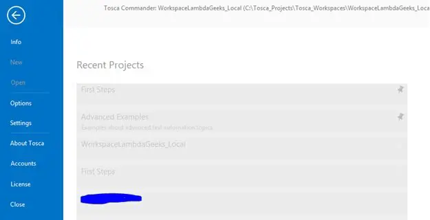
  • Info – It provides the details about the workspace.
  • New – It is used for creating a new workspace.
  • Open – We can open any existing workspace through this option.
  • Settings – We can view/change the configurations of different Tosca components.
  • Accounts  – We can log in to Tosca cloud through this option.
  • License – We can configure the license through this instead of using License wizard.
tosca commander - project
tosca commander – project

HOME: 

  • Search – We can search for any components which are available in Tosca workspace.
  • Project – We can view the hierarchy of different Tosca components or sections.
  • Scratch book – We can view the scratch book where the temporary execution logs are stored.
  • Sections – We can open any particular section.
  • Update all – If the workspace is connected with the common repository, we can sync the local copy of workspace with the common repository.
  • Checkin all – Commit/push any changes which are done in the local workspace into the common repository.
  • Checkout – Lock/reserve any particular root folder or components for an update. Through the checkout process, we can prevent other users from working on the same component.
  • Checkout Tree – It will check out all the child components available within the selected folder.
  • Import Subset – It is used to import any other subset or backup copy of workspaces.
  • Export – We can export the workspace copy as a subset/ backup.
  • Exploratory Testing – We can start the exploratory testing feature of Tosca Commander for scenario recording for testing or training purpose.
  • Manual Testcase – It’s used to create manual test cases.
  • Automated Test Case – It’s used to create automated test cases through recording.
tosca commander - home
tosca commander – home

TOOLS: 

Buffer Views – We can view the buffers which are created in the workspace. 

tosca commander - tools
tosca commander – tools

TEST CASES: 

The options available in these tabs are used for creating different components of test cases.

tosca commander - test cases
tosca commander – test cases

Create Folder –

It’s used to create any folder.

Run in Scratchbook –

We can execute any or part of test cases in the scratch book.  

API TESTING:

All the API Testing related options are available here. Please refer the API Testing section to learn more.

tosca commander - api testing
tosca commander – api testing

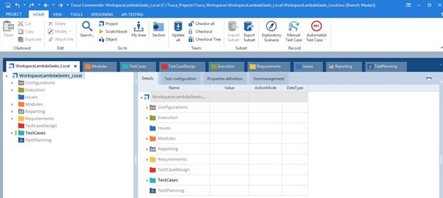
Sections of Tosca Commander: 

We are now going to understand the overview of different sections of the Tosca Commander, which are frequently used for test automation. Here all the sections have three parts –

  • Left position – Navigation/Hierarchy of folder/components 
  • Central position – Details of each selected folder/components, Test configuration (if applicable)
  • Right position – Properties of each selected folders or components.

Components of Tosca Commander:

We will discuss more on the important sections in the related topics of this tutorial.

Project – It provides the hierarchy view of the different folders/ components, available in the workspace. 

tosca commander - project section
Project Section of Tosca Commander

Module – Modules (AUT objects map) are stored here.

tosca commander - module section
Module Section of Tosca Commander

Testcase – Technical components of any test cases are saved here. 

tosca commander - testcase section
TestCase Section of Tosca Commander

TestCaseDesign – The test data which are required to execute any specific test case, can be kept in TestCaseDesign section. This approach helps to manage test data in efficient and dynamic way. Also the technical components and test data can be isolated through this section.

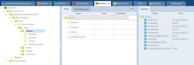
Execution – Test execution management can be done through this section. We can define execution list, trigger execution and analyzing the execution logs to investigate any issues.

tosca commander - execution section
Execution Section of Tosca Commander

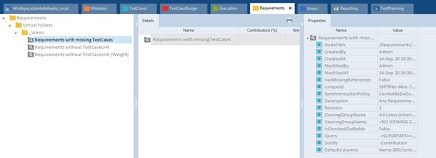
Requirements – Requirements related information is stored here. 

tosca commander - requirements section
tosca commander – requirements section

Issues – This section is used to maintain/ track any execution issues or bugs. Basically, defect management can be done through these options.

Reporting – Different kinds of standard or custom reports are stored here such as functionality coverage, execution status, requirement, bug status etc.

Test Planning – Plan and track all the testing activities as we work in Tricentis Tosca.

TOSCA User Management

In a Multiuser environment, the workspace data are stored in a central databases which is known as Common Repository. Multiple users should have the access to this repository. Here, Tosca User Management come into the picture to manages the users who are going to work with this workspace. The administrator has the rights to create, edit, delete any users. Also, access role can be defined for security purposes. To update data (modules, testcases, TDM, etc), first of all, user has to check out the component to restrict any other users to access it. After finishing the update, user has to check in the component to sync the update with the repository.

So, to connect the common repository, we need to provide access to each of the user .i.e. the administrator has to create individual users.

The below activities can be performed as a part of Tosca User management: 

  • · Create, activate user and assign groups.
  • · Assignment of roles.
  • · Deactivating users.
  • · Password reset.

Creating and activating user: 

Administrator has to follow the below steps to create and activate user – 

  • Step1# Open the project window via Home->Project.
  • Step2# Checkout root folder and switch to the Tosca User management tab. This shows all the user groups available with in the workspace.
  • Step3# Right-click on any of the user group and click on Create User icon and enter details to create the user.
  • Step4# Check the checkbox available in Enable column to activate the user. 
  • Step5# drag and drop the user in a different group to assign a different role. Also, we can change the user level.

Deactivating users: 

Uncheck the checkbox available in Enable column to deactivate any user.

Password Reset: 

Right-click on any user and click on Set Password option to create/update password.

tosca user management
Tosca User Management Section

Conclusion

Through out this “Tosca Commander and User Management” article of Tricentis Tosca Tutorial, we have explained about Tosca Commander and Tosca User Management approach which will going to help to develop the test case. Please click here to learn from Tricentis Support portal.

Tosca Workspace:Creation And Complete Guide

tosca workspace creation initial wizard

TOSCA Tutorial – Table of Content

While writing the “Tosca Workspace Creation” tutorial, we have used simple explanation so that entry level tester can understand the concepts easily. The entire Tosca tutorial is broken into below articles –

In this Tosca Workspace Creation article , we will discuss about step by step procedure to create Tosca workspace to start our hands on Tosca Automation activities. If you want to prepare for TOSCA Interview Questions, please click here.

TOSCA Workspace Creation

About Tosca Workspace

The Tosca workspace is acted as a repository of requirements, test cases, modules, and other components of Tosca. To develop, maintain or execute the test cases, we need to connect the workspace first. Otherwise, we will not be able to perform any automation activities. Workspace is created in the local drive. The workspace has to be defined in local work system. But it can also be defined in shared network drive. The data of the Tosca workspace, can be synched with different databases (SqlLite, SqlServer, DB2, Oracle) which an be acted as a central repository.

In a multiuser environment, i.e. more than one users are accessing the tool, the Tosca workspace has to created in central repositories. Tosca allows to create the workspace in different databases such as Oracle, SqlLite, DB2, SQLServer etc.

In a Singleuser Workspace, only one user is able to connect and work with Tosca. So, the central repository is not required here.

In the Multiuser Workspace, the data management is more simple and easier as the data are stored in shared databases which are known as common repositories. To perform any transaction (add, edit, delete) in a multiuser workspace, we need to lock the corresponding records first. It will restrict any other users to manipulate the same records. After completion of the transaction, w need to unlock the records. In Tosca, locking of data is know as check out and unlock is known as check in.

Common Repository Location Types: 

There are six different location types available to create a common repository for multiuser workspace. Those are – 

  • 1.     None – It’s applicable for single user workspace, i.e. no common repository is required.
  • 2.     Tricentis Cloud Repository – If we select this option, then the repository will be created in Tricentis hosted cloud server. To create this type of workspace, we need to login to Tricentis cloud during workspace creation.
  • 3.     SQLite – In this case, the repository will be created SQLite database. During the creatin, we need to specify 
  • the SQLite path and the repository name(only for creation) during the creation of workspace.
  • 4.     Oracle -Here, the repository has to be created in Oracle database. While creating the repository, we need to specify the Oracle schema name(optional) and the connection string  during the Tosca workspace creation.
  • 5.     MS SQL Server – In this case, the repository will be created SQL Server database. During the creatin, we need to specify the database schema name(optional) and the connection string during the creation of workspace.
  • 6.     DB2 – In this case, the repository will be created the DB2 database. During the creatin, we need to specify the database schema name(optional) and the connection string 
  • during the creation of workspace.

Note: After creating of the common Tosca repository, we need to access the workspace using the default user “Admin” with empty password. But while connecting the existing common repository, the user credential should have created prior to the creation of local workspace by the Admin. Also, to work with databases, the corresponding database driver should be installed.

Steps to Create Tosca Workspace:

  • 1. Open the Tosca Commander. 
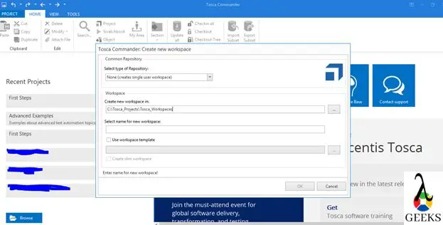
  • 2. Open new workspace creation wizard by the following navigation – PROJECT->New.
tosca workspace creation - initial wizard
tosca workspace creation – initial wizard
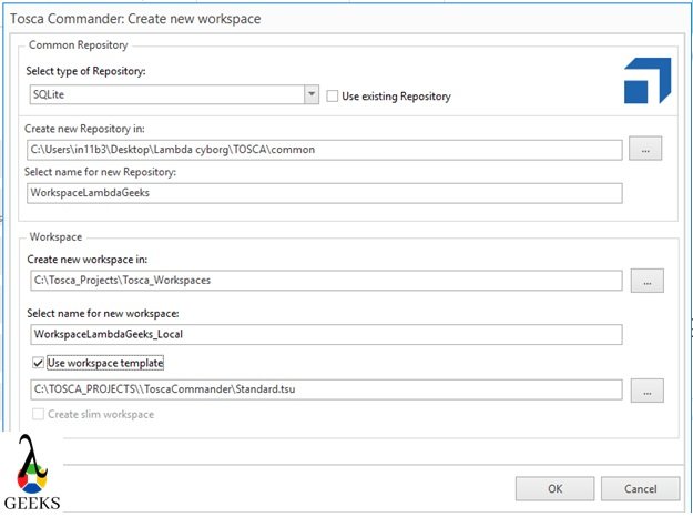
  • 3.     Enter below details based on the availability of fields –
    • “Select type of repository” – applicable for single user workspace.
    • “Use existing repository” – Select the checkbox if the common repository is already available.
    • “Create a new repository in” or ”Select existing repository” – It’s required for SQLite.
    • “Select name for new repository” – It’s required for SQLite.
    • “Schema name” – optional field while using Oracle, SQL Server and DB2 database.
    • “Connection string” – Connection string to connect the selected database.
    • “Create a new workspace in:” – Localdrive path where to create the local workspace.
    • “Select name for new workspace” – This field specify the name of the workspace.
    • “Use workspace template” – We need to check this while creating a common repository to load the default components.
  • 4.     In below example, we will be working with SQLite databases.
tosca workspace creation - initial wizard2
tosca workspace creation – initial wizard2
  • 5.     After entering all the details, we need to click on “OK” button to create the workspace. This step will take few minutes to complete. After the successful creation of workspace, the window will close automatically, and user authentication popup will appear to login to the workspace.
tosca workspace creation - login screen
tosca workspace creation – login screen
  • 6. After providing the default credential, we can open the workspace and start the working with Tosca Commander.
  • 7. After launching the Tosca for the first time, UI view will looks like –
tosca workspace creation - commander
tosca workspace – commander view

Conclusion

In this “Tosca Workspace Creation” article, we have explained about the steps of Tosca Workspace Creation process. It will help us to connect the workspace and start working with Tosca Commander. Please, click here to read more from Tricentis Support portal.

The Dobsonian Telescope: A Comprehensive Guide for Science Students

dobsonian telescope

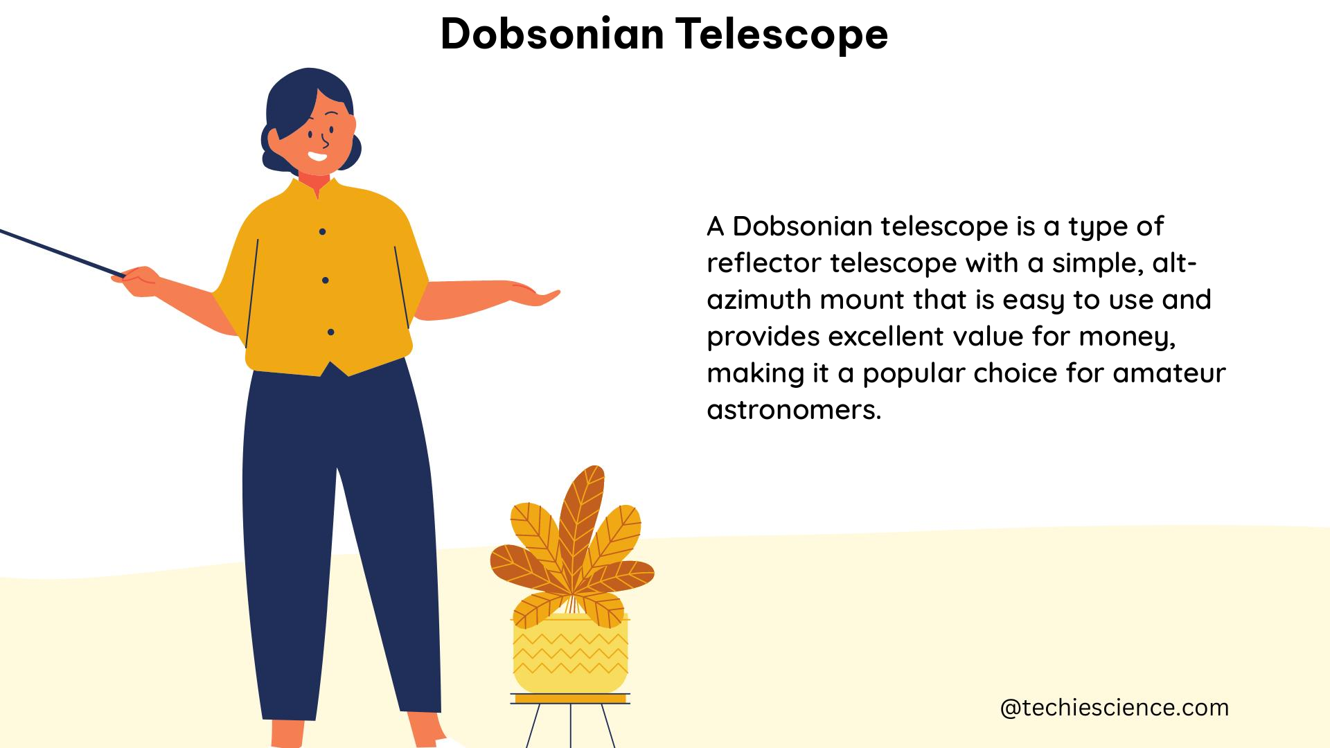
The Dobsonian telescope is a type of Newtonian reflector telescope that is renowned for its simplicity, ease of use, and exceptional light-gathering capabilities. This comprehensive guide will delve into the technical details and quantifiable data points that make the Dobsonian telescope a popular choice among amateur and professional astronomers alike.

Aperture: The Key to Brightness and Detail

The aperture of a Dobsonian telescope, which is the diameter of the primary mirror, is a crucial factor in determining the amount of light the telescope can collect. Dobsonian telescopes come in a wide range of aperture sizes, typically ranging from 6 inches to 30 inches or more. The aperture size is directly proportional to the telescope’s light-gathering power, as described by the formula:

Light-gathering power = (Aperture diameter)^2

For example, a 12-inch Dobsonian telescope has a light-gathering power that is four times greater than a 6-inch Dobsonian telescope, as the aperture diameter has doubled. This increased light-gathering power allows for brighter and more detailed views of celestial objects, such as galaxies, nebulae, and even faint deep-sky objects.

Focal Length and Focal Ratio: Balancing Magnification and Field of View

dobsonian telescope

The focal length of a Dobsonian telescope is the distance between the primary mirror and the focal point, where the image is formed. The focal length, in combination with the eyepiece, determines the magnification of the telescope. Dobsonian telescopes typically have a fast focal ratio, such as f/4 or f/5, which provides a wide field of view and makes it easier to locate and track celestial objects.

The focal ratio (f/ratio) of a Dobsonian telescope is the ratio of the focal length to the aperture. A lower f/ratio (e.g., f/4 or f/5) provides a wider field of view, which is beneficial for observing larger objects like galaxies and nebulae. Conversely, a higher f/ratio (e.g., f/10) provides a narrower field of view, making it more suitable for observing smaller objects like planets and the Moon.

The relationship between focal length and aperture can be expressed as:

Focal ratio = Focal length / Aperture

For example, a Dobsonian telescope with a 48-inch focal length and a 12-inch aperture would have an f/ratio of 4 (48 inches / 12 inches = 4).

Weight and Mount: Balancing Portability and Stability

Dobsonian telescopes can be quite heavy, with some models weighing over 100 pounds. The weight of the telescope is determined by the size of the primary mirror, the materials used in the construction, and the type of mount used.

Dobsonian telescopes employ a simple alt-azimuth mount, which allows the telescope to move up and down (altitude) and left and right (azimuth). This type of mount is easy to use and does not require complex alignment or adjustment, making it a popular choice for amateur astronomers.

The alt-azimuth mount works on the principle of two perpendicular axes of rotation, allowing the telescope to be pointed in any direction in the sky. The altitude axis controls the up-and-down motion, while the azimuth axis controls the left-and-right motion. This simple design, combined with the large aperture of Dobsonian telescopes, makes them highly portable and easy to set up, even for observers with limited experience.

Eyepieces and Focuser: Customizing the Viewing Experience

Dobsonian telescopes typically come with one or more eyepieces, which determine the magnification of the telescope. The eyepiece is inserted into the focuser, a device that holds the eyepiece in place and allows it to be adjusted for focus.

The magnification of a telescope is calculated by dividing the focal length of the telescope by the focal length of the eyepiece:

Magnification = Telescope focal length / Eyepiece focal length

For example, a Dobsonian telescope with a 48-inch focal length and an eyepiece with a 20mm focal length would have a magnification of 48 inches / 20mm = 24x.

Dobsonian telescope owners can experiment with different eyepieces to achieve the desired magnification and field of view for their observing needs. A wide range of eyepiece focal lengths, from low-power (e.g., 40mm) to high-power (e.g., 5mm), allows for versatile observing experiences.

Finderscope: Aiming the Telescope with Precision

Dobsonian telescopes often come equipped with a finderscope, a small auxiliary telescope mounted on the main telescope. The finderscope serves as a sighting tool, helping the observer quickly locate and center celestial objects in the main telescope’s field of view.

Finderscopes typically have a lower magnification than the main telescope, making it easier to acquire and track targets. The finderscope’s reticle, or crosshairs, provides a reference point for aligning the telescope with the desired object.

The relationship between the finderscope’s and the main telescope’s fields of view can be expressed as:

Finderscope field of view = Main telescope field of view / Finderscope magnification

For example, if a Dobsonian telescope has a 2-degree field of view and the finderscope has a magnification of 8x, the finderscope’s field of view would be 2 degrees / 8 = 0.25 degrees.

Optical Coatings and Mirrors: Enhancing Light Transmission and Reflection

The primary mirror of a Dobsonian telescope is typically made of glass or a lightweight material like Pyrex, and it is coated with a highly reflective material, such as aluminum or silver, to maximize light reflection.

The reflectivity of the primary mirror is an important factor in the telescope’s overall light-gathering and image quality. Aluminum coatings can achieve a reflectivity of around 90-92%, while enhanced coatings like protected silver can reach up to 98% reflectivity.

Additionally, the secondary mirror, which reflects the light from the primary mirror to the eyepiece, is also coated to enhance light transmission. Anti-reflective coatings on the secondary mirror and the eyepiece lenses can further improve the telescope’s overall optical efficiency.

Collimation: Aligning the Optical Components

Proper collimation, the alignment of the primary and secondary mirrors, is crucial for achieving optimal performance in a Dobsonian telescope. Misaligned mirrors can result in distorted, blurry, or off-center images.

The collimation process involves adjusting the tilt and position of the secondary mirror to ensure that the light path from the primary mirror is correctly focused on the eyepiece. This can be done using a collimation tool, such as a Cheshire eyepiece or a laser collimator, and following a step-by-step collimation procedure.

Maintaining proper collimation is essential for obtaining the best possible image quality and resolving power from your Dobsonian telescope.

Accessories and Upgrades: Enhancing the Observing Experience

Dobsonian telescope owners can further enhance their observing experience by investing in various accessories and upgrades. Some popular options include:

  1. Eyepiece sets: A range of eyepieces with different focal lengths can provide a variety of magnification options and fields of view.
  2. Barlow lenses: These accessories can double or triple the magnification of an eyepiece, allowing for higher-power observations.
  3. Filters: Specialized filters, such as nebula filters or moon filters, can enhance the contrast and visibility of specific celestial objects.
  4. Cooling fans: These fans can help stabilize the temperature of the primary mirror, reducing air turbulence and improving image quality.
  5. Telrad finders: These zero-power reflex sights can provide a quick and easy way to locate targets in the sky.
  6. Dew shields and heaters: These accessories can prevent dew formation on the telescope’s optics, ensuring clear and unobstructed views.

By exploring these accessories and upgrades, Dobsonian telescope owners can tailor their observing setup to their specific needs and preferences, further enhancing their overall astronomical experience.

Conclusion

The Dobsonian telescope is a remarkable instrument that combines simplicity, ease of use, and exceptional light-gathering capabilities. By understanding the technical details and quantifiable data points discussed in this comprehensive guide, science students and amateur astronomers can make informed decisions when selecting and using a Dobsonian telescope.

Whether you’re a beginner or an experienced observer, the Dobsonian telescope offers a versatile and rewarding platform for exploring the wonders of the night sky. With its large aperture, wide field of view, and user-friendly design, the Dobsonian telescope continues to be a popular choice among stargazers of all levels.

Reference:

  1. The Dobsonian Telescope: A Practical Guide for Building Large Aperture Telescopes
  2. Dobsonian Telescope Designs
  3. How to Build a Dobsonian Telescope
  4. Telescope Optics: A Comprehensive Resource
  5. Astronomy Essentials: Understanding Telescope Aperture

The Cassegrain Telescope: A Comprehensive Technical Guide

cassegrain telescope

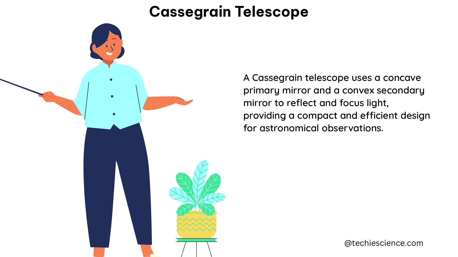
The Cassegrain telescope is a type of reflecting telescope that uses a parabolic primary mirror and a hyperbolic secondary mirror to produce a flat image. This design offers several advantages, including a compact and lightweight structure, a long effective focal length, and the ability to correct for various optical aberrations. In this comprehensive guide, we will delve into the technical specifications and advanced features of the Cassegrain telescope, providing a valuable resource for science students and enthusiasts.

Understanding the Effective Focal Length (EFL)

The effective focal length (EFL) of a Cassegrain telescope is a crucial parameter that determines the overall performance of the system. The EFL is the distance from the center of the primary mirror to the point where the image is formed. The EFL can be calculated using the following formula:

EFL = Focal Length of Primary Mirror × (1 + (Distance between Mirrors / Focal Length of Primary Mirror))

For example, in a Maksutov-Cassegrain telescope with a primary mirror focal length of 1200mm and a distance between mirrors of 150mm, the EFL would be:

EFL = 1200 × (1 + (150 / 1200)) = 1350mm

This formula demonstrates how the distance between the primary and secondary mirrors can affect the EFL, allowing for the design of Cassegrain telescopes with a wide range of focal lengths.

Focal Ratio and Image Scale

cassegrain telescope

Another important measurement for a Cassegrain telescope is the focal ratio, which is the ratio of the EFL to the diameter of the primary mirror. The focal ratio determines the field of view and the image scale of the telescope. A Cassegrain telescope with a primary mirror diameter of 200mm and an EFL of 2000mm would have a focal ratio of:

Focal Ratio = EFL / Primary Mirror Diameter = 2000 / 200 = 10

The focal ratio is a crucial factor in the design of Cassegrain telescopes, as it affects the overall size and weight of the instrument, as well as the image quality and resolution.

Misalignment Measurements at the VLT

The Very Large Telescope (VLT) provides a unique perspective on the technical specifications of Cassegrain telescopes. The VLT has both Nasmyth and Cassegrain focii, and is optimized to be a Ritchey-Chrétien telescope at the Nasmyth focus. However, the Cassegrain focus has a different configuration, with a different set of aberrations.
To correct these aberrations, the VLT uses a closed-loop active optics correction system. This system measures the misalignment of the mirrors and adjusts their positions to correct for any errors. The misalignment measurements are typically done at eight evenly distributed points at the edge of the field of view, and take at least fifteen minutes to complete.

During this time, the VLT optics can change significantly due to elastic deformations caused by changes in the zenith distance. To account for these changes, the VLT uses a least-squares fit to obtain the values for the misalignment angles, and subtracts the variation generated by the change of altitude between the correction at the center and the measurement at the edge.

Calculating the Change in Angle

The expected change in the angle between the axes of the primary and secondary mirrors due to a rotation of the primary mirror around its vertex can be calculated using the following formula:

Change in Angle = (20″ × Primary Mirror Diameter) / (Circumference of Primary Mirror)

For example, a VLT with a primary mirror diameter of 8.2 meters would have an expected change in angle of:

Change in Angle = (20″ × 8.2) / (2π × 8.2) = 0.0031″

This formula demonstrates the importance of accurately measuring and correcting for any misalignment in the Cassegrain telescope’s mirrors, as even small changes in the angle can have a significant impact on the overall performance of the instrument.

Advanced Features and Aberration Correction

Cassegrain telescopes can be further optimized through the use of advanced features and aberration correction techniques. One such example is the Ritchey-Chrétien design, which uses a hyperbolic primary mirror and a hyperbolic secondary mirror to correct for coma and other off-axis aberrations.

Another technique is the use of active optics, where the shape of the primary mirror is actively controlled to correct for deformations and other aberrations. This is particularly important in large telescopes like the VLT, where the primary mirror can be subject to significant deformations due to changes in the telescope’s orientation and environmental conditions.

Additionally, Cassegrain telescopes can be designed with specialized coatings and materials to improve their performance in specific wavelength ranges, such as infrared or ultraviolet. These advanced features and aberration correction techniques allow Cassegrain telescopes to achieve high-quality, high-resolution images for a wide range of astronomical observations.

Conclusion

The Cassegrain telescope is a versatile and technologically advanced instrument that has played a crucial role in modern astronomy. By understanding the technical specifications and advanced features of Cassegrain telescopes, science students and enthusiasts can gain a deeper appreciation for the engineering and physics behind these powerful instruments. This comprehensive guide has provided a detailed overview of the effective focal length, focal ratio, misalignment measurements, and aberration correction techniques that are essential to the design and operation of Cassegrain telescopes.
References:

  • A. Glindemann, et al., “4 Misalignment measurements at the VLT,” Astronomy & Astrophysics, vol. 354, pp. 66-74, 2000.
  • Guilherme de Almeida, “Effective focal lenght in a Maksutov-Cassegrain,” Cloudy Nights, 2016.
  • M. K. Kim, et al., “Experimental investigation of binodal astigmatism in nodal aberration theory (NAT) for a customized, high-performance astronomical instrument,” Optics Express, vol. 29, no. 13, pp. 19427-19441, 2021.
  • Y. Zhang, et al., “Quantification of Propagation Modes in an Astronomical Instrument,” arXiv preprint arXiv:2308.06156, 2024.
  • ResearchGate, “An example Cassegrain telescope system with a primary mirror at F/1.2, a Cassegrain focus of F/8, and a 90° fold mirror in the F/8 converging beam,” Optics and Photonics, 2021.

51 Appium Interview Questions(Most Beginner’s Don’t Know!)

App package7 1024x535 1

In this tutorial, we will discuss the top 50 Appium interview questions and Answers. It will help you to prepare for the interview and crack it.

We will divide the questions and answers into three parts:

Basic Appium interview Questions

What is Appium?

Ans: Appium is an open-source freely distributed mobile UI testing framework.

What types of application can we automate with Appium?

Ans: Appium supports native application, Hybrid applications and Web-views.

List out the Appium abilities?

Ans: For this answer please refer to this Link.

List out the prerequisite to use Appium?

Ans: We need below tools/jar/plugins to work with Appium

  1. JDK
  2. ANDROID studio
  3. IntelliJ/Eclipse
  4. TestNG plugin or dependency if you use Maven
  5. Appium java client

Mention the disadvantages or limitations of Appium?

Ans: Like every tool, Appium also has certain limitations. Please check the answer here.

What are the native Apps?

Ans: Please check the answer from here.

What are hybrid apps?

Ans: Please check the answer from here

What do you understand by M-Web or Mobile Web Apps?

Ans: Please check the answer from here.

What are the supported languages in Appium??

Ans: Appium allows clients to interact with Appium based on sessions. Clients send session requests as a form of POST and pass desired capabilities as a parameter. There are multiple clients like Java, JavaScript, PHP, Ruby, Python, and C#.

Mention the advantages or benefits of using Appium.

Ans: The answer is the same as Question 3. You will find the answer here

List out the Appium supported Automation and Unit Test Framework ?

Ans: We can use all type of test frameworks with Appium. For example, java unit, java TestNG, NUnit etc as unit test framework . Appium test implements the Selenium webDriver to interact with Android or iOS devices.

Mention the limitations or disadvantages of Appium?

Ans: The answer is the same as Question 5. You will find the answer here

How can you verify elements on the iOS app?

Ans: For the iOS app, we can verify the elements using Appium inspector. It is an excellent tool to identify the elements’ id, XPath etc. It can also perform to perform user actions.

What is the Appium inspector?

Ans: Appium inspector is used to inspecting DOM to find out the elements both in Android and iOS. We can record the actions we perform in the inspector. It can generate the scripts in different languages like Java/JUnit, python etc. For a complete guide on Appium inspector, please click here.
How to inspect the DOM element or XPath for mobile application?

Ans: You can find the DOM element or XPath in Couple of ways. Either you can use “UIAuteviewer/UIAutomateviewer2”, or you can use Appium inspector for Android. For iOS, you can use Appium inspector. To learn how to inspect element, please refer to this link.

What’s the difference between simulator with emulator ?

Ans: Emulator and simulator both are visual devices. The emulator is a virtual device for Android, and simulator is a virtual device for iOS launched from Xcode.

How much time does Appium take to automate a test?

Ans: It depends on the scenario you are testing. If you are verifying multiple flows in a single method, it is likely to take more time. But it is always better to make the test cases precise and straightforward so that if any issue occurs in between your execution, you can have the recovery mechanism.

When should we use Appium?

Ans: Appium supports native, mobile web app and hybrid app. It supports cross-platform testing. If you have running on Android or iOS and want to verify it, you can use Appium.

What’s the best approach while Testing is it on real devices or emulators/simulators?

Ans: Again, this is depending on your test scenarios, application behaviours. If it is a straightforward application, you can test both on real devices or simulator/emulator. But if your application has complex logic, it is always better to go for real devices. Generally, we should use these to automate because it is ultimately the end-user who is going to use these applications. Real devices also have issues when connecting to the computer for a long time. ADB connections get lost, and it will show devices not attached, which will fail your test cases.

How to identify M-Web or Mobile Browser objects using Appium?

Ans: UserAgent can be used to identify objects in a M-Web or Mobile Browser. It provides you an way to alter the browser by using mobile proxy to resolve the issue.
Or we can use ChromeCasting for object identification in a Mobile Browser. Using Chromecast, your mobile to the system connection could be established and then you could do inspect elements on mobile from the chrome casting system.

What approach to take to identify the unique object in Appium while same class name having multiple objects

Ans: driver.findElements(By.className) gives the lists off elements. Once we get the lists, we need to traverse through the indexes to handle the elements uniquely with the same class name.

Perform the comparison among Appium and Selenium ?

Ans: As we know Selenium is an open-source tool. It helps to automate web application.On the other hand Appium is also an open-source tool. It uses to automate mobile application( Native, Hybrid, Web-apps). Appium implements Selenium Webdriver to interact with the devices.

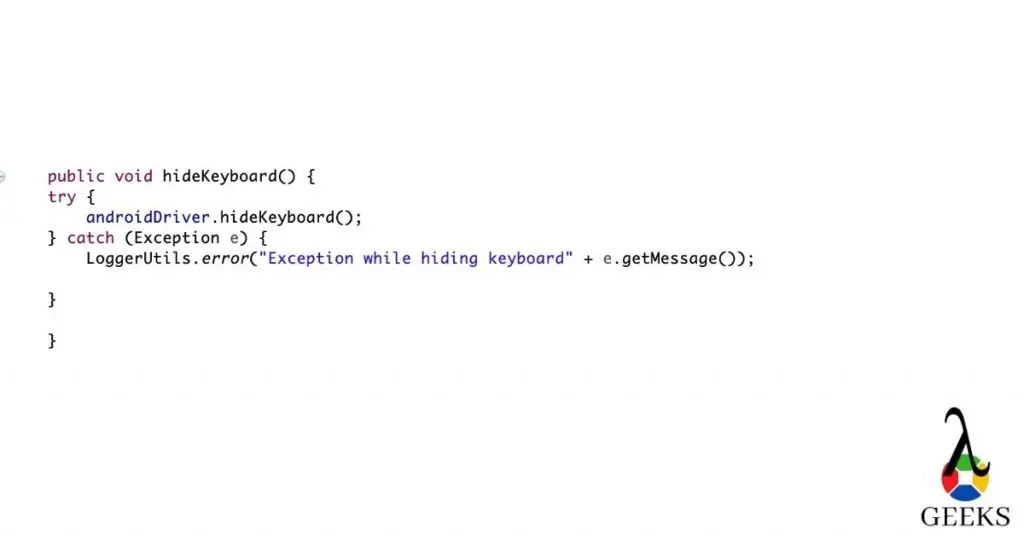
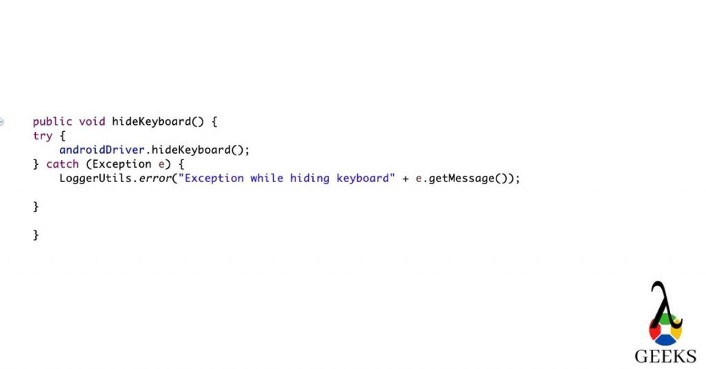
How to hide the keyboard in Appium?

how to hide keyboard
Appium interview questions: How to hide keyboard

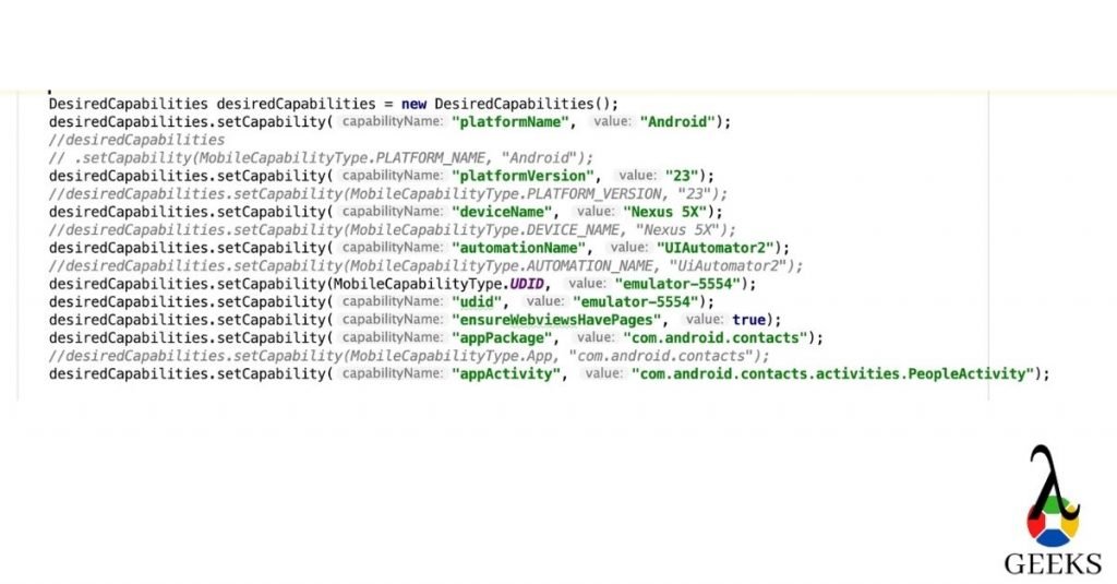
What are the desired capabilities required for Android?

desired capabilities for android
Appium interview questions: desired capabilities for android

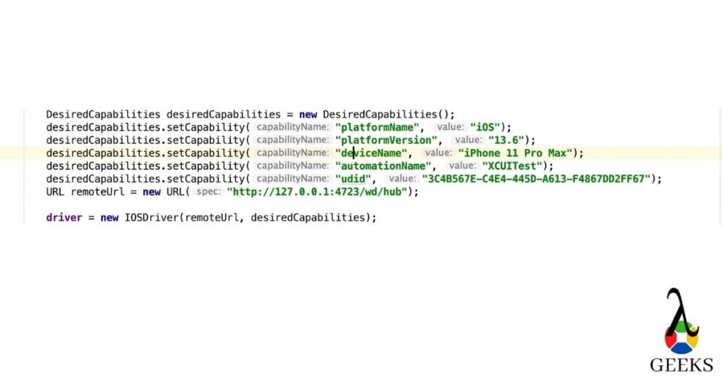
What are the required desired capabilities for iOS?

desired capabilities for iOS
Appium interview questions: desired capabilities for iOS

Intermediate Appium Interview Questions

What Data Exchange is when you do testing on Mobile devices?

Ans: Data exchange in Appium exchange the data hosted by complex objects which actually are being stored in different components of Web-view based app. One example can be the window object.

What are the errors you face in Appium?

Ans:

  • “The following desired capabilities are needed but not provided: Device Name, platformNameError.”
  • “Could not find adb. Please set the ANDROID_HOME environment variable with the Android SDK root directory pathError.”
  • “openqa.selenium.SessionNotCreatedException: A new session could not be createdError.”

What are the conditions to write Appium tests?

To write an Appium test, we must follow the below points:

Appium client: This is an Appium client written in a different language which connects to the Appium server. For example, Appium Java client. 

Appium Session: Appium interacts with mobile devices based on sessions. We need to create a session with the help of Appium client. 

Desired Capabilities: Desired Capabilities are like parameters which we pass while creating the session. It helps the Appium server to identify the devices uniquely.

Driver command: Driver command is nothing but the user actions we perform in devices. For example click() or sendKeys().

How can you verify elements in the Android Native Application?

Ans: You can use “UIAuteviewer/UIAutomateviewer2”, or you can use Appium inspector for Android.

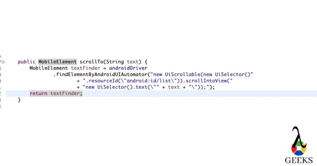
How to scroll down in an App?

how to scroll down
Appium interview Questions: how to scroll down

Is it possible to start the Appium server programmatically?

Ans: Yes, we can programmatically initiate the Appium server session. As Appium uses node.js, we can create .bat file(for Windows) or shell file/command(Linux/Mac) to start the Appium server passing bootstrap port, hub IP and port.

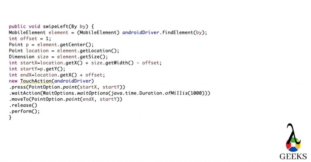
How to swipe left in Appium?

how to swipe left
Appium interview questions: how to swipe left

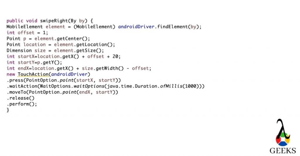
How to swipe right in Appium?

how to swipe right
Appium interview questions: how to swipe right

Is it possible to run a parallel/multithreaded test in Appium?

Ans: Yes we can run tests on the multithreaded environment, but the condition is to make sure that same Appium server should not used to parallelize the two tests.

Mention the Parallel Testing approach in IOS using Appium?

Ans: Appium has given an option to run iOS tests in parallel from Xcode version 9 and above. There are a couple of prerequisites we need to follow.

  1. “UDID” should be unique.
  2. “wdaLocalPort” should be unique
  3. derivedDataPath root should be unique for each driver instance. 
  4. Sauce Labs gives an option to run iOS tests parallel. We have to upload our Appium test to sauce labs. After that, it will run in multiple iOS tests in parallel.

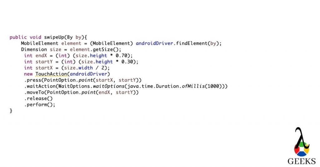
How to swipe up in Appium?

how to swipe up
Appium interview questions: how to swipe up

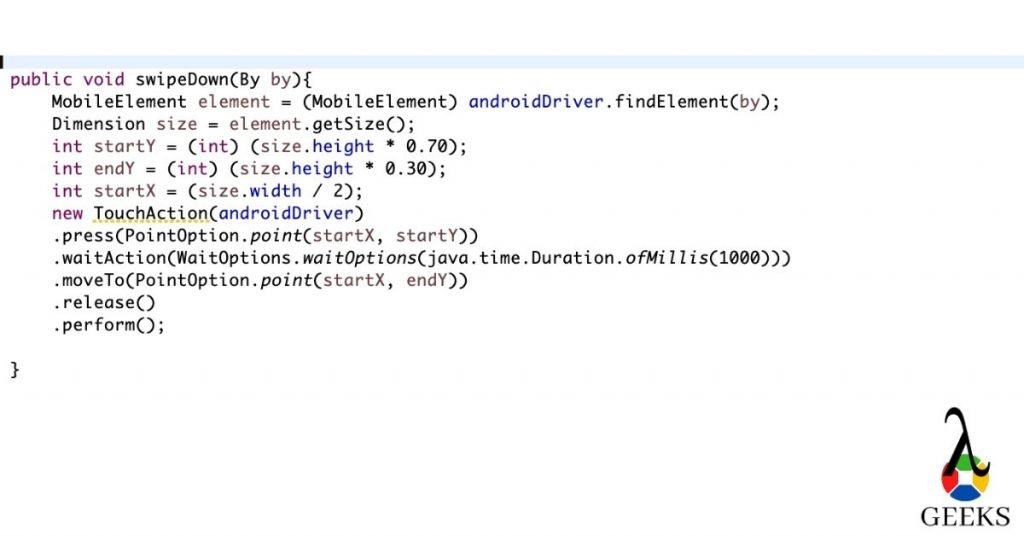
How to swipe down in Appium?

how to swipe down
Appium interview questions: how to swipe down

Advanced Appium Interview Questions

What are the selenium commands works with Appium?

Ans: Appium implements Selenium WebDriver. That’s why almost all the WebDriver commands work with Appium. Few examples are mentioned below:

  • Click() command for clicking/tapping the button/links.
  • sendKeys() command to send the value.
  • It supports java scripts commands.
  • Handles alerts.
  • It can switch between the context in web-views.

What are the advantages of Real devices over emulator/Simulator?

 There are a couple of advantages using real devices over emulator/Simulator

  1. We can check low battery scenarios with real devices.
  2. How fast battery gets drained out during testing.
  3. We can check the actual performance of the devices and do app profiling.
  4. We can check Bluetooth related scenarios.
  5. We can check messages and phone calls.

What are the different tools for debugging in Android and iPhone?

Ans: We verify the logs to debug the issues occur in the devices. For Android we can check Monitor, “adb logcat” or “dumpsys” . For the iPhone, we can use iPhone configuration utility.

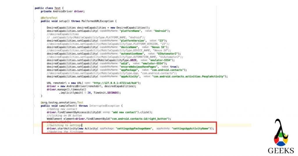
How can you switch between Android applications?

switch between Android app
Appium interview questions: Switching between android app

How can you switch between iOS applications?

how to switch between iOS app
Appium interview questions: Switching between iOS app

How can you find bundle id in iOS?

  • Copy the .ipa file to your systems and change the extension to .zip file
  • Now unzip the folder and search for iTunesMetadata.plist file
  • Once you get the file, open it in an editor and search for softwareVersionBundleId. It will give you the bundle id.

How can you enable the wifi while the phone is in Airplane mode?

ConnectionStateBuilder connection = 
new ConnectionStateBuilder();
driver.setConnection
(connection.withWiFiEnabled()
.build());));

How can you enable unicode keyboard ?

Ans: We need add below desired capabilities:

desiredCapabilities.setCapability("unicodeKeyboard", true);

How can you copy-paste in Appium?

Ans: Well, no direct method is there to do it. However you can get the value using getText() or getAttributes() methods and pass the same value to the sendKeys().

How to handle WebDriverAgentRunner-Runner.app encountered an error (Failed to install or launch the test runner issue?

rm '/usr/local/bin/carthage' 
brew install carthage 
brew link carthage

There might be other possible solutions to this problem. You can refer this link for other solutions.

When will choose automation testing over manual testing?

Ans: Automation testing will help during regression testing. If you have any complex scenarios or repetitive scenarios, you should automate it.

When will you choose manual testing over automation testing?

When you have new applications, you should test it manually first and probably then automate it. There are specific scenarios where you have to verify from logs/events; we should verify those manually. Scenarios where we don’t need frequent testings, we should not automate those.

How Appium works?

  • We have covered this part in our initial post. Please see the answer here.

How to double click in Appium?

double clicking
Appium interview questions: How to double click

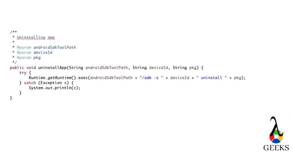
How to uninstall the app in Android?

Unistalling the app
Appium interview questions: How to uninstall the app

How to clear the app data in Android?

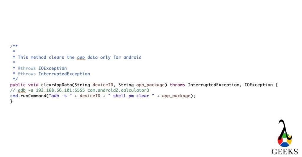
App package14
Appium interview questions: How to clear the app data

How will you handle failure cases in Appium ?

Ans: It depends upon the scenarios. If any test cases get failed, we need to restore the app state in order to execute the  next test cases. You can do it either in @AfterMethod or using listeners.

How to make your pass percentage higher in Appium?

Ans: Automating app using Appium sometimes makes the scrips inconsistent. If you run the test cases for longer times or may be due to network issues you can face the inconsistency issue. To make the script more robust we can take the following approach.

Is there any EventListeners in Appium?

Ans: yes, you can use AppiumWebDriverEventListener . You need to implement this interface .

Example:

public class AppiumListener implements AppiumWebDriverEventListener {
   public void beforeChangeValueOf(WebElement webElement, WebDriver webDriver) {
   }
   public void afterChangeValueOf(WebElement webElement, WebDriver webDriver) {
   }
   public void beforeAlertAccept(WebDriver webDriver) {
   }
   public void afterAlertAccept(WebDriver webDriver) {
   }
   public void afterAlertDismiss(WebDriver webDriver) {
   }
   public void beforeAlertDismiss(WebDriver webDriver) {
   }
   public void beforeNavigateTo(String s, WebDriver webDriver) {
   }
   public void afterNavigateTo(String s, WebDriver webDriver) {
   }
   public void beforeNavigateBack(WebDriver webDriver) {
   }
   public void afterNavigateBack(WebDriver webDriver) {
   }
   public void beforeNavigateForward(WebDriver webDriver) {
   }
   public void afterNavigateForward(WebDriver webDriver) {
   }
   public void beforeNavigateRefresh(WebDriver webDriver) {
   }
   public void afterNavigateRefresh(WebDriver webDriver) {
   }
   public void beforeFindBy(By by, WebElement webElement, WebDriver webDriver) {
   }
   public void afterFindBy(By by, WebElement webElement, WebDriver webDriver) {
   }
   public void beforeClickOn(WebElement webElement, WebDriver webDriver) {
   }
   public void afterClickOn(WebElement webElement, WebDriver webDriver) {
   }
   public void beforeChangeValueOf(WebElement webElement, WebDriver webDriver, CharSequence[] charSequences) {
   }
   public void afterChangeValueOf(WebElement webElement, WebDriver webDriver, CharSequence[] charSequences) {
   }
   public void beforeScript(String s, WebDriver webDriver) {
   }
   public void afterScript(String s, WebDriver webDriver) {
   }
   public void beforeSwitchToWindow(String s, WebDriver webDriver) {
   }
   public void afterSwitchToWindow(String s, WebDriver webDriver) {
   }
   /**
    * will work if there is any exception found in the scripts
    * @param throwable
    * @param webDriver
    */
   public void onException(Throwable throwable, WebDriver webDriver) {
       System.out.println("Execute Exception");
   }
   public <X> void beforeGetScreenshotAs(OutputType<X> outputType) {
   }
   public <X> void afterGetScreenshotAs(OutputType<X> outputType, X x) {
   }
   public void beforeGetText(WebElement webElement, WebDriver webDriver) {
   }
   public void afterGetText(WebElement webElement, WebDriver webDriver, String s) {
   }
}

Till now, we have covered three types of Appium interview questions. These are Basic Appium interview questions, Intermediate Appium interview questions and Advanced level of Appium interview questions. This tutorial will help you to prepare for Appium interview questions and give you the confidence to crack it. To learn in-depth on Appium, you can refer to this link.

Reference: Appium

Eddy Current Brake Design Application: A Comprehensive Guide for Science Students

eddy current brake design application

Eddy current brakes are a fascinating application of electromagnetic induction, offering a unique and efficient way to slow down or stop moving objects. These brakes harness the power of induced currents to generate opposing magnetic fields, creating a braking force that can be precisely controlled and measured. In this comprehensive guide, we will delve into the intricacies of eddy current brake design, providing science students with a detailed playbook to understand and experiment with this technology.

Understanding the Principles of Eddy Current Brakes

Eddy current brakes work on the principle of electromagnetic induction, where a moving conductive material, such as a metal plate or disc, passes through a magnetic field. This interaction induces eddy currents within the conductive material, which in turn generate their own magnetic fields. These opposing magnetic fields create a braking force that opposes the motion of the moving object, effectively slowing it down or bringing it to a stop.

The strength of the eddy current brake can be quantified by the force it generates, which is proportional to the square of the velocity of the moving part, the magnetic field strength, and the area of the stationary part. This relationship can be expressed mathematically using the formula:

F = B^2 * A * v^2 / R

Where:
F is the force generated by the eddy current brake (in Newtons)
B is the magnetic field strength (in Teslas)
A is the area of the stationary part (in square meters)
v is the velocity of the moving part (in meters per second)
R is the resistance of the stationary part (in ohms)

By understanding and applying this formula, you can design and optimize eddy current brakes for various applications.

Measuring the Strength of Eddy Current Brakes

eddy current brake design application

To quantify the strength of an eddy current brake, you can measure several key parameters:

  1. Damping Coefficient (b): This is a measure of the force generated by the eddy current brake. In the laboratory activity described in the references, the damping coefficient was found to range from 0.039 N s m^-1 to 0.378 N s m^-1, depending on the specific combination of track and magnet used.

  2. Kinetic Friction Coefficient (μ): This is a measure of the force required to move the magnet along the track in the absence of an eddy current brake. In the same laboratory activity, the kinetic friction coefficient was found to range from 0.20 to 0.22.

  3. Velocity (v): The velocity of the moving part, such as a magnet or a wheel, is a crucial parameter in determining the strength of the eddy current brake.

  4. Magnetic Field Strength (B): The strength of the magnetic field generated by the stationary part, such as a metal plate or rail, is another important factor in the performance of the eddy current brake.

  5. Area of the Stationary Part (A): The size and geometry of the stationary part, which interacts with the moving part, also contribute to the overall braking force.

  6. Resistance of the Stationary Part (R): The electrical resistance of the stationary part, typically a conductive material like aluminum or copper, affects the induced eddy currents and the resulting braking force.

By measuring these parameters, you can not only quantify the strength of the eddy current brake but also use the formula F = B^2 * A * v^2 / R to calculate the expected braking force.

Designing a DIY Eddy Current Brake

To demonstrate the principles of eddy current braking, you can set up a simple DIY experiment using a neodymium magnet disc and an aluminum bar. Here’s how you can do it:

  1. Materials: Obtain a neodymium magnet disc (e.g., 30 mm diameter, 5 mm thick, and approximately 40 grams) and an aluminum bar (e.g., 920 mm long, 40 mm wide, and 3 mm thick).

  2. Experimental Setup: Place the aluminum bar on a flat surface. Release the neodymium magnet disc from a height and allow it to slide down the aluminum bar.

  3. Measurements: Measure the time it takes for the magnet to slide down the aluminum bar. You can use this information to calculate the force generated by the eddy current brake using the formula:

F = m * g / t

Where:
F is the force generated by the eddy current brake (in Newtons)
m is the mass of the magnet (in kilograms)
g is the acceleration due to gravity (9.8 m/s^2)
t is the time it takes for the magnet to slide down the bar (in seconds)

  1. Magnetic Field Strength and Area: You can also measure the magnetic field strength of the neodymium magnet and the area of the aluminum bar to calculate the expected force using the formula:

F = B^2 * A * v^2 / R

Where:
B is the magnetic field strength (in Teslas)
A is the area of the aluminum bar (in square meters)
v is the velocity of the magnet (in meters per second)
R is the resistance of the aluminum bar (in ohms)

By performing this simple DIY experiment, you can gain a hands-on understanding of the principles of eddy current braking and explore the relationship between the various parameters that influence the braking force.

Advanced Applications of Eddy Current Brakes

Eddy current brakes have a wide range of applications beyond the simple DIY setup. Some advanced applications include:

  1. Linear Electromagnetic Launchers: Eddy current brakes can be used in linear electromagnetic launchers, such as those used in maglev trains, to control the acceleration and deceleration of the moving object.

  2. Vibration Damping: Eddy current brakes can be used to dampen vibrations in machinery, reducing the risk of damage and improving overall system performance.

  3. Dynamometer Testing: Eddy current brakes are commonly used in dynamometers, which are devices used to measure the power output of engines or electric motors.

  4. Magnetic Levitation: Eddy current brakes can be used in magnetic levitation systems, where the braking force is used to counteract the lifting force and maintain a stable levitation.

  5. Regenerative Braking: In electric vehicles, eddy current brakes can be used in regenerative braking systems, where the kinetic energy of the vehicle is converted into electrical energy and stored in the battery.

These advanced applications often involve more complex designs and require a deeper understanding of electromagnetic principles, material properties, and system dynamics. As a science student, exploring these applications can provide valuable insights into the versatility and potential of eddy current brakes.

Conclusion

Eddy current brakes are a fascinating and versatile technology that offer a unique way to control the motion of moving objects. By understanding the underlying principles, measuring the key parameters, and designing simple DIY experiments, science students can gain a comprehensive understanding of eddy current brake design and its applications.

This guide has provided a detailed playbook for science students to explore the world of eddy current brakes, from the fundamental physics to the advanced applications. By mastering the concepts and techniques presented here, you can unlock new opportunities for research, innovation, and practical applications in various fields of science and engineering.

References

  1. J. A. Molina-Bolívar and A. J. Abella-Palacios, “A laboratory activity on the eddy current brake,” Eur. J. Phys., vol. 33, no. 3, pp. 697–707, 2012.
  2. J. A. Molina-Bolívar and A. J. Abella-Palacios, “A laboratory activity on the eddy current brake,” ResearchGate, 2012. [Online]. Available: https://www.researchgate.net/publication/254496903_A_laboratory_activity_on_the_eddy_current_brake.
  3. A. K. Singh, M. Ibraheem, and A. K. Sharma, “Parameter Identification of Eddy Current Braking System for Various Applications,” in Proceedings of the 2014 Innovative Applications of Computational Intelligence on Power, Energy and Controls with their Impact on Humanity (CIPECH), Ghaziabad, India, 2014, pp. 191–195.
  4. H. Li, M. Yang, and W. Hao, “Research of Novel Eddy-Current Brake System for Moving-Magnet Type Linear Electromagnetic Launchers,” in Proceedings of the 2019 Cross Strait Quad-Regional Radio Science and Wireless Technology Conference (CSQRWC), Taiyuan, China, 2019, pp. 1–3.
  5. [Online]. Available: https://electronics.stackexchange.com/questions/472827/how-strong-are-eddy-current-brakes.

Tosca Setup:Tosca Download,Install,Config(Complete Guide!)

Tricentis Tosca Setup Download 1

Summary of Tricentis TOSCA Tutorial

We have segregated the entire Tosca tutorial in to below articles. We have wrote this article(TOSCA Tutorial) in simple language and keep the article short with the required concepts only so that any entry level software tester can understand this article in a shorter span of time.

In this article Tricentis Tosca Setup, we will discuss about step by step procedure to Install Tosca, uninstall and license configuration. If you want to prepare for TOSCA Interview Questions, please click here.

Download TOSCA

Trial Version:

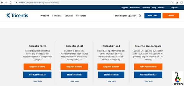
  1. Open Tricenties official site to download software.
  2. Click on the “Request a Demo” button available in right top corener of the website available in section Tricenties Tosca.
Tricentis Tosca Download 1
Tosca Setup Download 1
  • Enter the details in the form and click on “Request Demo” button to submit.
Tricentis Tosca Setup Download 2
Tosca Setup Download 2
  • Once the form has been submitted, Tricenties support team will contact you for the demo and understand the expectations. After that you will be able to request for trial version of tosca through email/ telephone.

Download for registered user:

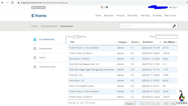
Open the tricentis support portal and download the latest tosca version in your local drive. In this article, we will work with TOSCA 13.2 Patch Level 3.

Tricentis Tosca Setup Download 3

INSTALL TOSCA

Basic System Requirement for Tosca Commander:

Hardware requirements:

  • CPU: i5 Dual-Core 2.4Ghz
  • RAM: 8GB
  • Hard disk space: 10GB
  • Network: 100 mbps

Software requirements:

  • Microsoft® .NET Framework Version 4.8 (Win 7, Win 8.1, Win 10)
  • Microsoft Visual C++ 2010, 2012, 2013, 2015.
  • 32 bit or 64 bit(recommended) – both are supported by tosca.

For more details on system requirements for TOSCA installation, please visit tricentis support portal.

Installation Steps:

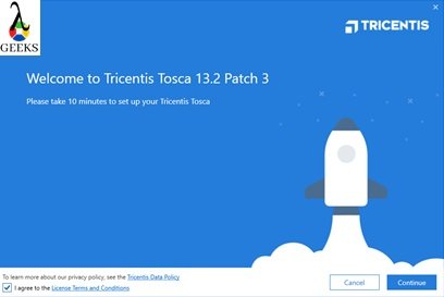
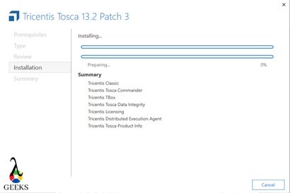
  • Step#1: Click on Installation Setup file from local directory.
  • Step#2: Accept License agreement and Continue.
Tricentis Tosca Setup Installation 1
Install Tosca Setup 1
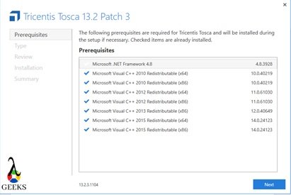
  • Step#3: After auto verification of prerequisites, click on Next to proceed.
Tricentis Tosca Setup Installation 2
Install Tosca Setup 2
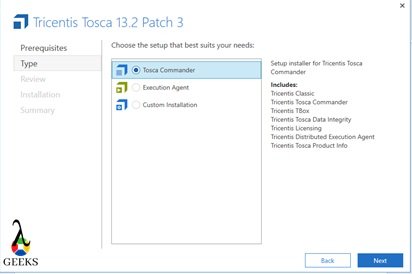
  • Step#4: Select Tosca Commander option for standard installation. But you can customize or installation based on the requirements. After the selection click on Next to proceed.
Tricentis Tosca Setup Installation 3
Install Tosca Setup 3
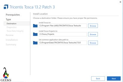
  • Step#5: Change Installation paths if required and Next.
Tricentis Tosca Setup Installation 4
Install Tosca Setup 4
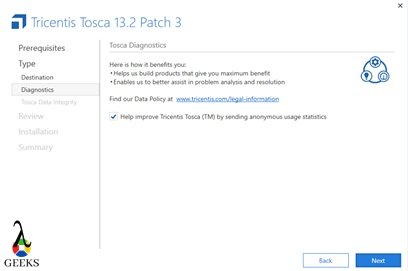
  • Step#6: Please select the checkbox if you want to send the usage statistics to Tricentis. Click on Next.
Tricentis Tosca Setup Installation 5
Install Tosca Setup 5
  • Step#7: Review and click on Install.
Tricentis Tosca Setup Installation 6
Install Tosca Setup 6
  • Step#8: Accept if any popups and wait for installation to be completed.
Tricentis Tosca Setup Installation 7
Install Tosca Setup 7
  • Step#9: Once done, please click on Finish to complete installation.
Tricentis Tosca Setup Installation 8
Install Tosca Setup 8
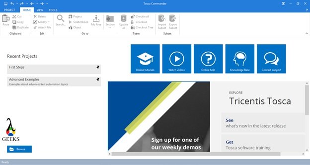
  • Step#10: Open TOSCA Commander from start menu to verify installation.  
Tricentis Tosca Setup Installation 9
Install Tosca Setup 9

Uninstall TOSCA

During up-gradation of Tricentis Tosca it is strongly recommended to completely uninstall Tricentis Tosca and install latest version to avoid any unexpected errors.

Uninstall Process Steps:

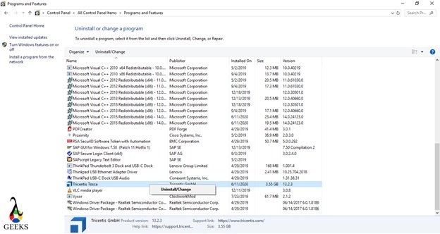
  • Step#1: Navigate to Control Panel and Click on “Programmes and Features”:
  • Step#2: Select Tricenties Tosca and Click on Uninstall:
Tricentis Tosca Setup Uninstallation
Tosca Setup Uninstallation
  • Step#3: Wait for process completion and restart the system.

Tricentis Tosca License Configuration

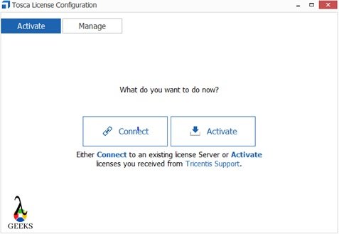
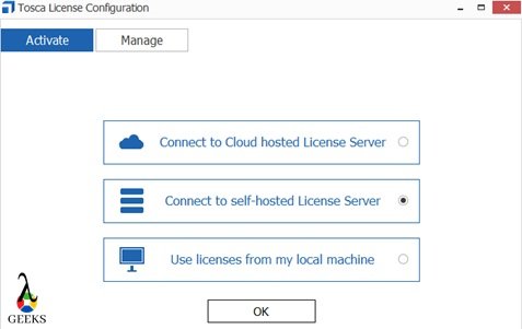
  • Step#1: Open the “Tosca License Configuration” wizard from the start menu.
Tricentis Tosca Setup License Configuration 1
  • Step#2: Based on the available licenses, please select the desire option. And click Ok. Here we are selecting second option i.e. “Connect to Self-Hosted License Server”.

Tricentis Tosca Setup License Configuration 2
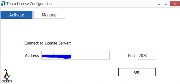
  • Step#3: Enter the license server details and click on OK to complete the configuration. Default post should be 7070.
Tricentis Tosca Setup License Configuration 3
  • Step#4: License Configured successfully.
Tricentis Tosca Setup License Configuration 4
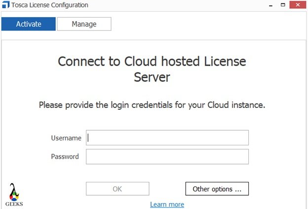
  • Step#5: For trial license, at step2, please select the first option and enter the user details which are created after registering in Tricentis portal.

Tricentis Tosca Setup License Configuration 5

Conclusion

In this article of Tricentis Tosca Tutorial, we have covered the setup of Tricentis TOSCA testing tool so that we can start with working with Tosca. Click here to understand more from Tricentis Support portal.

Please click to read the next article of TOSCA Tutorial – Complete Study of TOSCA Commander.

Eddy Current Testing: A Comprehensive Guide for Science Students

eddy current testing

Eddy current testing (ECT) is a non-destructive testing (NDT) method used to detect discontinuities in conductive materials. It is based on the principle of electromagnetic induction, where an alternating current (AC) flows through a coil, creating an alternating magnetic field. When this magnetic field comes in close proximity to a conductive material, it induces eddy currents within the material, which in turn generate their own magnetic field, causing a change in the electrical impedance of the coil. This change in impedance can be used to identify changes in the test piece.

Principles of Eddy Current Testing

Eddy current testing relies on the principle of electromagnetic induction, which is described by Faraday’s law of electromagnetic induction. According to Faraday’s law, when a conductive material is exposed to a time-varying magnetic field, it induces an electromotive force (EMF) within the material, which in turn generates eddy currents.

The mathematical expression of Faraday’s law is:

ε = -N * dΦ/dt

Where:
– ε is the induced EMF (in volts)
– N is the number of turns in the coil
– dΦ/dt is the rate of change of the magnetic flux (in webers per second)

The induced eddy currents within the conductive material create their own magnetic field, which opposes the original magnetic field according to Lenz’s law. This interaction between the original magnetic field and the eddy current-induced magnetic field causes a change in the impedance of the coil, which can be measured and used to detect defects or changes in the material.

Factors Affecting Eddy Current Testing

eddy current testing

The performance of eddy current testing is influenced by several factors, including:

  1. Frequency of the Alternating Current: The frequency of the AC used in the coil affects the depth of penetration of the eddy currents. Higher frequencies result in shallower penetration, while lower frequencies allow for deeper penetration.

  2. Electrical Conductivity of the Material: The electrical conductivity of the test material determines the strength of the eddy currents induced within it. Materials with higher conductivity, such as copper and aluminum, will have stronger eddy currents compared to materials with lower conductivity, like stainless steel or titanium.

  3. Magnetic Permeability of the Material: The magnetic permeability of the test material affects the distribution and strength of the eddy currents. Materials with higher permeability, such as ferromagnetic materials, will have a greater influence on the eddy current field.

  4. Lift-off Distance: The distance between the probe and the test material, known as the lift-off distance, can significantly affect the eddy current signal. Variations in lift-off distance can be mistaken for defects or changes in the material.

  5. Geometry of the Test Piece: The shape and size of the test piece can influence the eddy current distribution and the interpretation of the results. Complex geometries or the presence of edges and corners can create distortions in the eddy current field.

  6. Defect Characteristics: The size, depth, orientation, and type of defect in the test material can affect the eddy current response. Larger, shallower, and more conductive defects are generally easier to detect than smaller, deeper, or less conductive ones.

Applications of Eddy Current Testing

Eddy current testing has a wide range of applications in various industries, including:

  1. Aerospace: ECT is extensively used in the aerospace industry for the detection of surface and near-surface defects in aircraft components, such as fuselage, wings, and landing gear.

  2. Automotive: ECT is employed for the inspection of automotive components, including engine parts, transmission components, and suspension systems.

  3. Power Generation: ECT is used for the inspection of power plant components, such as turbine blades, heat exchanger tubes, and generator rotors.

  4. Oil and Gas: ECT is utilized for the inspection of pipelines, storage tanks, and other infrastructure in the oil and gas industry.

  5. Manufacturing: ECT is employed for the quality control of manufactured products, including metal castings, forgings, and welds.

  6. Corrosion Detection: ECT can be used to detect and monitor corrosion in various structures, such as bridges, buildings, and storage tanks.

  7. Tube and Pipe Inspection: ECT is a valuable tool for the inspection of heat exchanger tubes, boiler tubes, and other piping systems.

Eddy Current Testing Instrumentation

Eddy current testing systems typically consist of three main subsystems:

  1. Probe Subsystem: The probe subsystem includes one or more coils designed to induce eddy currents into the test material and detect changes within the eddy current field. Probes can be designed for specific applications, such as surface inspection, subsurface inspection, or tube inspection.

  2. Eddy Current Instrument: The eddy current instrument generates the alternating current that flows through the coil, creating the alternating magnetic field. It also measures and processes the changes in the coil’s impedance caused by the interaction with the eddy currents.

  3. Accessory Subsystem: The accessory subsystem includes devices such as scanners, recorders, and data acquisition systems that enhance the capabilities of the eddy current system. These accessories can be used to automate the inspection process, record and analyze the data, and improve the overall efficiency of the testing.

The most common output devices used in eddy current testing include:

  • Meter readout
  • Strip chart
  • X-Y recorder plot
  • Oscilloscope display
  • Video screen presentation

These output devices allow for the measurement and analysis of both the amplitude and phase angle of the eddy current signal, which are crucial for the identification of defects or changes in the test material.

Advantages and Limitations of Eddy Current Testing

Advantages of Eddy Current Testing:

  • Non-Destructive: ECT is a non-destructive testing method, which means the test piece is not damaged during the inspection process.
  • Rapid Inspection: ECT can examine large areas of a test piece very quickly, making it an efficient inspection method.
  • No Coupling Liquids: ECT does not require the use of coupling liquids, which simplifies the inspection process.
  • Versatile Applications: ECT can be used for a wide range of applications, including weld inspection, conductivity testing, surface inspection, and corrosion detection.

Limitations of Eddy Current Testing:

  • Conductive Materials Only: ECT is limited to conductive materials, such as metals, and cannot be used on non-conductive materials like plastics or ceramics.
  • Shallow Penetration: The depth of penetration of eddy currents is limited, making ECT more suitable for the detection of surface or near-surface defects.
  • Sensitivity to Lift-off: Variations in the lift-off distance between the probe and the test material can significantly affect the eddy current signal, which can be mistaken for defects.
  • Complexity of Interpretation: Interpreting the results of ECT can be complex, as the eddy current signal is influenced by various factors, such as material properties, geometry, and defect characteristics.

Conclusion

Eddy current testing is a versatile and widely used non-destructive testing method that relies on the principle of electromagnetic induction. By understanding the underlying principles, factors affecting the performance, and the various applications of ECT, science students can gain a comprehensive understanding of this important NDT technique. With its ability to rapidly inspect conductive materials for surface and near-surface defects, ECT continues to play a crucial role in the quality control and maintenance of a wide range of industrial products and infrastructure.

References

  1. Olympus-IMS.com. (n.d.). Introduction to Eddy Current Testing. Retrieved from https://www.olympus-ims.com/en/ndt-tutorials/eca-tutorial/intro/
  2. NAVAIR 01-1A-16-1 TM 1-1500-335-23. (n.d.). Eddy Current Inspection Method. Retrieved from https://content.ndtsupply.com/media/Eddy%20Current%20-USAF-Tech-Manual-N-R.pdf
  3. ScienceDirect. (n.d.). Eddy Current Testing – an overview. Retrieved from https://www.sciencedirect.com/topics/engineering/eddy-current-testing
  4. NCBI. (2012). Non-Destructive Techniques Based on Eddy Current Testing. Retrieved from https://www.ncbi.nlm.nih.gov/pmc/articles/PMC3231639/