Direct Current Examples:Detailed List of Applications and Examples on DC current uses

Direct current is a current which flows in One Direction without changing its polarity with time.

This article will discuss Direct Current Examples such as DC generator, DC motor, battery, electronic circuits, electroplating, solar power supply, high-voltage direct current transmission, etc.

Some Direct Current Examples:

DC generator

We know that generators can be either AC or DC type of generator, the design of DC generators is very much simple, parallel operations are more straightforward, and the system is mostly stable.

DC generator is a type of generator that converts the mechanical form of energy into DC electricity, this kind of generator generates DC power supply.

And that DC power generated from DC generator is used for testing purposes in different laboratories, used for charging batteries, exciting the alternators, and can be used as a portable generator that supplies small power, can be used for driving motors, etc.

DC Motor

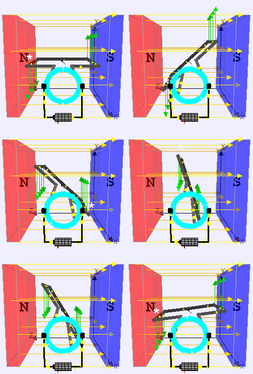
DC motor is an application of DC electric current which converts the direct electric current into mechanical energy creating a magnetic field.

The magnetic field generates the DC powers due to the attraction and repulsion in the magnetic field, and the rotor starts to rotate. DC Motors are used where high torque or accurate speed control over an extensive range is needed.

There are different types of DC Motors which have various applications, such as Elevators, conveyors, rolling mills, Trolleys, Cranes, heavy planers, steel mills, locomotives, excavators, drilling machines, etc.
Battery

Different types of batteries are available that can be recharged by using external power supply set as Nickel- metal hydride, Lithium-ion, Nickel-cadmium, lead-acid, lithium-ion polymer, and other alkaline rechargeable batteries.

While recharging any battery DC is required, DC power supply is used for recharging any battery, as with DC, the electron will flow in one constant direction back into the battery creating the potential difference needed when the battery is fully charged.

An Alternative Current (AC) cannot be used for recharging a battery because the positive half of the AC cycle will charge the battery, where the negative half of the AC cycle will discharge the battery. While recharging the battery, the specification of the battery must be taken into consideration and adjust the current to the proper levels.

Electronic Circuits

Electronic circuits are the concept of MOSFET, BJT, diodes, transistors, logic circuits, integrated circuits, etc.

As DC does not change its polarity with time, with constant and stable magnitude value, there is no power factor or the phase shift, so for proper biasing of the transistor, diode, or any other electronics element, constant DC is preferred.

As AC does not maintain any direction of current flow as it reverses direction periodically, the operation of any electronic components is not possible with an AC power supply.

For example, for proper operation of IC, any IC needs a ripple-free and pure DC power supply as input to generate the required output. Electronics are primarily digital devices that operate using either on or off or high or low signals. When AC is used as a power supply for electronic circuits as for the frequency of AC supply, every second generates lots of on or off signals, which is harmful to the electronic circuit operations.

The processor of the electronic circuit won’t be able to determine the difference in on or off signal in case of any e noise present in that AC signal. While using DC power supply to the electronic circuits, the biasing of any circuit element can be determined or controlled easily. DC is very stable, easy to manage, and accurate; using DC supply to electronic circuit makes it easy to handle or operate any electronics circuit.

Many electronics use an adaptor to convert AC to DC as generally power supply at home is AC power supply, so for proper operations, for example, flashlight charger, television adaptor, computer adaptor, electrical vehicle adaptor phone charger, etc.

Electroplating

For the electroplating procedure, a DC power supply is preferred over AC. Electroplating is a process in which a metal gets deposited over other metal plates in the presence of metal salt.

When DC supply is used in electroplating, one metal gets oxidized, and the ions from that metal get dissolved in the electrolytic solution and then get reduced at the other metal, which is known as electroplated metal while forming a cote on the electroplated metal of electroplating ions.

As for the principle of electroplating, each metal plate must be maintained at opposite polarity at constant during the continuous procedure, which is only possible by supplying a DC. If an AC supply is used, the polarity of both metal plates or electrodes will change continuously, and the ions will oscillate back and forth between electrodes or metal plates where electroplating is not possible. Even if pulsating DC can be used as the direction of the current is not changing with time.

Solar Power Supply

Photovoltaic cell converts the light into a DC using photovoltaics effect, so the power generated from a solar panel is a DC power.

Photovoltaics system uses a solar panel that receives sunlight directly and then converts that light into electric power, while the electricity generated is DC, but can fluctuate with the intensity of sunlight, so before practical use, that DC voltage is required to convert into desired DC voltage or AC, by the use of filters or inverters.

Many photovoltaic power systems are connected to the grid for use on a larger scale, such as satellites, Lighthouse, batteries, etc. By using a grid-connected photovoltaic system, the capacity of any photovoltaic system can be maximized to 10 kilowatts for different requirements of the consumers.

Installing solar panels
Image Credit: “Installing solar panels” by OregonDOT is licensed under CC BY 2.0

High Voltage Direct Current (HVDC) transmission

HVAC stands for high voltage direct current, which is used for power transmission over enormous distances.

High Voltage Direct Current (HVDC) is preferred over High Voltage Alternating Current (HVAC) for transmitting power of more than 600 km. So transmitting power using HVDC through a long transmission line is way cheaper than that of HVAC For distance over break-even distance.

undefined
Image Credit:Diagram costs over line length (distance) in comparision HVAC 3-phase systems versus HVDC systems By wdwd – Own work, CC BY 3.0,

As for transmission lines, HVDC has only required two conductors where HVAC requires three or more than three conductors, HVDC has a uniform magnetic field with constant magnitude throughout the transmission, so HVDC has relatively lower losses than HVAC transmission. The power flow in HVAC lacks compatibility relative to HVDC, and intelligence between asynchronous systems for intelligent grids while using HVDC is relatively more straightforward than HVAC. In DC, there is no frequency or phase shifts.

Telecommunication

The telecommunication network uses a DC power supply, as negative 48 volt DC is found in the landline; the AC power supply is not in the used invoice line because the AC power supply will disturb and disrupt communication.

DC power supply is not restricted to any frequency vibration or landing power factor in telecom. DC power can be easily stored for backup in telecom buses. The battery is used, which provides a DC power supply without any power conversion loss.

Why Do We Use AC Instead Of DC:Interesting Aspects on Different Industires and Home

This article has discussed the various points why do we use AC instead of DC in multiple applications or appliances used in homes and industries.

Let’s discuss different application why do we use AC instead of DC as:

  • Alternative current (AC) can be a step-down or step-up very easily by using various methods such as transformer to required value while losing minimum energy during conversion, as transformer works efficiently with AC power supply.
  • Alternating current (AC) is used in industry for transmission in the generation of electricity as generation of alternating current is much cheaper and easier than that of a DC voltage. For Higher voltages and AC has much better efficiency in DC during transmission. 
why do we use AC instead of DC
Image Credit: Diagram costs over line length (distance) in comparision HVAC 3-phase systems versus HVDC systems By wdwd – Own work, CC BY 3.0,
  • The devices that convert electrical energy into any mechanical energy use Alternative Current as a power supply, as when energy conversion is easier with AC as loss during conversion is lower the DC power conversion.
  • Generally, for all types of operations in transformer, transformer use of AC supply is the main power supply. Where DC supply does not work properly with transformer as DC cannot easily generate an alternating magnetic field. The fundamental requirement for the operation of the transformer needs a change in the magnetic field, which induces the voltage in the second coil.
  • High-voltage AC is relatively more efficient than DC for sending electricity over a significant distance. High Voltage generation in AC is relatively more accessible than that in DC.
  • A Single-phase AC power supply is used in the home. In contrast, a three-phase AC power supply is used for commercial and steel facilities to accommodate high-voltage load better, for easy generation, transmission, and less maintenance requirement.
  • An AC induction motor is easy to use, whereas a DC induction motor for proper working requires an additional commutator brush and switches.
  • Arc generated in an AC circuit can be easily extinguished or can be self-extinguished, given that an AC has two zero-crossing points in its every complete cycle. In contrast, Arc generated in DC is much stronger and cannot be self-extinguished as DC does not have any zero-crossing.
1024px Types of current.svg
Image Credit: Alternating current or AC (green curve). Direct Current or DC (red line), The horizontal axis measures time (it also represents zero voltage/current) ; the vertical, current or voltage. By Zureks – Own work, Public Domain,
  • The AC generator is more efficient than the DC generator. Due to various losses in DC generators such as eddy current loss, mechanical loss, sparking, copper loss, and hysteresis loss, DC generator efficiency reduces. An AC generator does not require a commutator; maintaining an AC generator is much easier than that of a DC generator. The AC generator is very easily able to generate high voltage relative to the DC generator.
  • Adding switches in the AC circuit is relatively more accessible than that of the DC circuit. When the AC circuit is switched off, a voltage Spark is generated inside the switch, which gets self-extinguished as AC has two zero-crossing points in its complete circle. Wherever in DC, both current and voltage are constant when switched off in DC circuit, the voltage is generated inside the switch stays for longer than that of AC if an Arc stays for longer in the circuit switch contacts making it burnt, pitted, overeating or premature switch failure.
  • Three-Phase AC supply is used because with a three-phase supply, the electrical power is more consistent, which allows the machine to run more efficiently, and the device becomes more durable
  • Three-phase AC energy system is used in various industries which use has high power demand three-phase AC system is used because power delivering through three-phase AC system is constant, can be used for more efficient use of materials, the installation cost is lower, the size of equipment reduces with the use of three-phase power supply etc
  • In the household, the three-phase connection is not required as the power consumption is not as high as industries, but if there are a lot of heavy appliances used in a house, then a three-phase connection may be installed as a requirement
  • Single-phase AC connection is generally used in residential appliances as single-phase AC is more efficient up to 1000 watts, design costs less, and the design is simple, the large array of application use of single-phase AC supply.
  • Three-Phase power supply is used in mobile towers, data centres, aircraft, power grids, ship boards, etc. it is as well as many electronic loads that need more than 1000 watts of power for operation
  • The three-phase power supply is used in power-hungry and high-density data centres. In high-density data centres, a more powerful computing system is being used and is packed in a small area. Some racks hold several servers that can draw 20 to 30 KW of power, so constant power and efficiency matter; that’s why a three-phase AC supply is used. By using a three-phase AC supply in the high-density data centre, losses can be minimised as well as load balancing across power is more straightforward, which results in optimum utilisation of power supply.
  • AC drivers are widely in use in process industries to increase the efficiency of each piece of equipment. AC drivers control the speed of the electric motor as a requirement which reduces the overall energy consumption by 30 to 40%. In contrast, AC drivers in the industry used to regulate and control types of equipment such as conveyors, fans, machine spindles, etc.
electricity 2864988 640
Image by F. Muhammad from Pixabay
  • The cable size of the AC power supply is somewhat lighter relative to the DC power supply cable for the same rating.
  • Electrosurgery uses the characteristics of a high-frequency alternating current for the removal or destruction of tissue. In this procedure, the high oscillating current is used to heat the tissue; the degree of destruction depends on the frequency of oscillation and the power of the supply current.
  • Because of the two advantages of AC over DC on generation and transmission, alternate marine power (AMP) uses AC for operation.
  • A general air conditioner uses AC over DC; some Air Conditioner uses DC for operations, but that DC AIr conditioner has low power applications. Air Conditioners require AC because of their high power consumption applications.
  • The motor, which uses AC as a power supply, requires lower startup power and has better control over starting current and acceleration can be customised into various speed and torque requirements and ac Motors are more durable than DC Motors.
  • In alternating, current can be easily converted to direct current by using a rectifier, filter, diode, etc. The conversion from DC to AC can be done by a complicated circuit of an inverter that costs much more than that of AC to DC Converter.

Do We Use Ac Or Dc:Interesting Aspects on Different Industries and Home

276169274 822a7f2693 b

Electricity has two forms: alternating current AC and direct current DC, so there is always a comparison between AC or DC, Tesla has supported AC where Edison has supported the DC mode of electricity.

Although alternating current AC is comparatively more used than that of DC, this article will discuss where do we use AC or DC in different aspects.

Uses of Alternating Current:

Alternating Current (AC) has its benefits as well as drawbacks. There are different applications where AC is used over DC as per the requirement of operation.

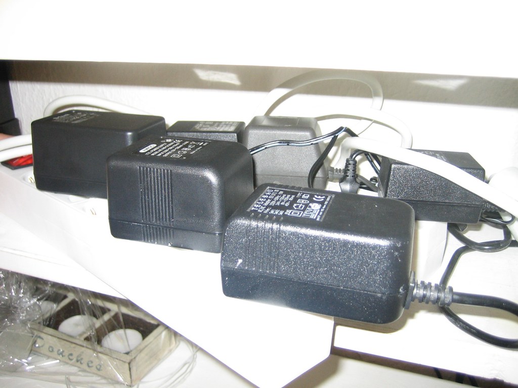
Power Adaptors
Image Credit: “Power Adaptors” by schoschie is licensed under CC BY 2.0

Let’s discuss where do we use ac or dc, The following is where the AC power supply is used :

  • Alternating current is generally used in industry for transmission and generation of electricity as the generation of alternating current (AC) is much easier than that of Direct Current (DC) for high voltages, as AC has better efficiency than DC.
  • DC loses more power to heat relative to AC which causes a higher risk of producing fire, burning appliances, high-cost maintenance and complicated conversion between high voltage and low current to low voltage and high current in DC using Transformers, so in place of DC most industry prefers AC.
  • In the household, there are many appliances that convert electrical energy into mechanical energy that devices use AC power supply such as dishwasher, refrigerator, washing machine, etc.
  • The AC motor (uses AC as power supply) depends on the reversing magnetic field produced by alternating current. The DC motor requires brushes to make electrical contact with the moving coil. In contrast, an AC motor does not require it, which makes AC to operate AC motors easily.
  • Generally, all kind of transformer uses AC supply as DC supply does not work with transformers. The DC Transformer is there but designing that kind of transformer is complicated than a regular transformer.
  • AC induction motors are used for large-sized industrial Servo Motors, which often require variable frequency drives to allow control of their speed.
  • High Voltage AC is more efficient than DC for sending electricity over a considerable distance; that is why high voltages from power plants are supplied to the home, which can be easily converted to required voltage or current by using a transformer.
  • An induction motor or heater uses AC as supply; if DC supply is used in induction motor, commutator and brush will be required as extra part in motor, which will wear out very easily the motor. The need for the replacement of the brush or commutator will be very much frequent. Using the AC in the induction motor makes the overall cost less, the motor will last longer. Maintenance will not be required as a DC induction motor. As for induction heating, the heat is generated by Eddy current, which requires an alternating current eddy current that is not present in DC.
  • The air conditioner uses AC as a supply instead of DC, and there is some air conditioner that uses DC, but that air conditioner has Limited power applications. Although the Air conditioner uses DC, the main supply is always an AC supply. The inverter of the Air conditioner converts the AC to DC then uses it.
  • For home and residential applications, only a single-phase AC power supply is used. A three-phase AC supply is used as 3 phase supply for commercial and industrial facilities to accommodate high loads better. A single-phase AC supply is used when loads are lighting or heating, and a three-phase AC supply is used for large machines for electric motors.
  • The power factor of 3 phase AC motors is high, which means they require less voltage for the load. The motor that uses a three-phase can start with only a power supply. It can even reverse its direction if needed, whereas the motor that uses a single-phase AC cannot start itself; they require an external power supply or device for starting it.
  • Use of AC Motors is preferred for Air Conditioning compressor, power drives, hydraulic and irrigation pump etc.
  • The airline industry uses AC as the main electrical power supply over DC supply. If needed, the AC will be converted to DC using a transformer rectifier unit for the airline. The engine-driven alternator supplies containers powered to AC essentials by an AC bus, where some large turboprops have both AC or DC generators.
  • 3 phase synchronous motor is used for application which needs operating at constant speed such as air compressor motor-generator Rolling Mills paper and cement industry etc
  • Single-phase synchronous motor is used in clocks teleprinters and every kind of timing device, recording instrument, sound recording and reproducing instrument.

Use of Direct Current:

Direct current also has its benefits as well as drawbacks. There are different applications where DC is used over AC because of its efficiency or the specific operation’s requirement.

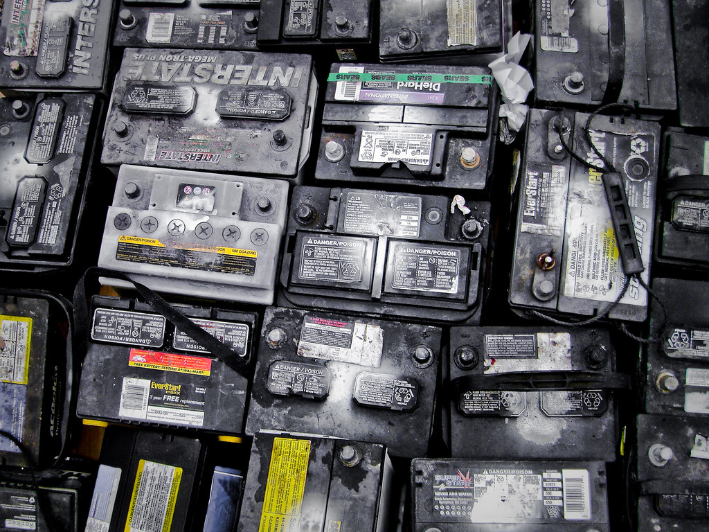
Batteries
Image Credit: “Batteries” by spatulated is licensed under CC BY 2.0

Here are the following where DC supply is used :

  • Different devices or appliances (mainly digital electronic appliances) at home use DC as a supply, such as a microwave oven, computer, phone, etc.
  • DC has better transmission than AC due to laser losses in AC
  • DC is mainly used with appliances that use batteries. Every charger adaptor used in our houses is a converter from AC to DC, such as phone chargers, flashlight chargers, televisions, computers, hybrid or electric verticals, etc.
  • DC is generally used for long-distance transmission. As the transmission of AC power is very much Limited to short or medium range distance maximum distance, AC power cover is 800 km approximately.
  • High voltage DC has better transmission than AC due to laser losses in AC.
  • For local generation DC is much better than that of AC as conversion between AC to DC is expensive.
  • Both rechargeable and non-rechargeable types of battery supplies are always DC rechargeable battery need DC for recharge.
  • Currents generated from solar panels are the DC units of solar panels; an inverter is used to enable DC to AC conversion.
  • Where stable speed torque or operation is required, the steady energy flow of DC is used for operation off Motors.
  • DC motor is used for steel mill rolling equipment, paper machine, etc.
  • Series DC motors are used for heavy-duty applications such as electric locomotives, lifts, cranes, Steel Rolling Mills etc.
  • DC shunt motor is used for operating appliances or devices at constant speed such as vacuum cleaners, woodworking machines, conveyors, elevators, grinders, shafts, small printing presses etc.

AC Circuit Vs Dc Circuit:Comparative Analysis On Different Aspects

In the AC system, voltage and current change their polarity and magnitude at a specific interval of time; the AC system is widely used because of its advantages.

This article will discuss the Ac circuit vs DC circuit, the advantages of AC over DC, etc.

Why is AC used over DC?

The use of DC is very much limited to some devices; for more significant scale generation, distribution, transmission, etc., AC is adopted. AC has been in use for ages.

Advantages of AC over DC:ong>

ACDCAC can be stepped down or stepped up easily using the various methods or by using Transformer as Transformer works for AC properly. Ac can be easily scaled to the desired level with very low energy loss.DC cannot be stepped down or Step Up easily as the Transformer does not work appropriately with DC.
AC generation costs less than that of DC generationGeneration of DC is costlier than that of AC generation
AC can be converted easily into DC using a rectifier, filter, etc.DC to AC converter is complicated. 
AC devices or the motor which uses AC as a power source are economical, robust, and durable. DC devices or instrument which uses DC as a power supply are costlier and less durable. 
The maintenance cost of AC equipment or device is very much cost-effective Maintenance of DC equipment or devices can cost much more than that of AC devices or types of equipment.
At high voltages, AC can be generated.Due to commutation difficulty is a DC cannot be generated at high voltages.
Switchgear is simple for AC circuits.Switchgear is complicated for DC. It required additional measures to work properly.
AC Transmission and distribution are economical as well as loss in AC power due to transmission is relatively lesser than that of DC transmission.DC Transmission and distribution are costlier as well as loss in DC power due to transmission is relatively more than that of AC.
AC generator has high efficiency.The DC generator is less efficient than that of an AC generator.
AC does not have to face much of electrolytic corrosionDC has more Electrolytic corrosion
Arc generated in AC is lower in strength and can be self-extinguished as AC has zero crossing in its cycle.Arc generated in DC is much stronger and cannot be self-extinguished as DC does not have any zero-crossing.
The AC Induction motor  is easy to use or maintainThe DC Induction motor, for proper working, requires a commutator, brushes, and switches.
ac circuit vs dc circuit
Image Credit : AC signal and DC pulsating signal By Omegatron – Own work, CC BY-SA 3.0,

Other Differences between AC and DC are:

AC Circuit vs DC Circuit:

ACDC
An AC circuit current its direction (or polarity) and its magnitude periodically.DC circuit current flows only in one direction; only magnitude can vary polarity of voltage, or current does not change with time.
AC signal has a specific frequencyDC does not have any specific frequency to define it. 
The amplitude of the AC signal changes continuously.The amplitude of DC can change, but polarity remains fixed.
AC cannot be used to directly for electroplating, electrolytic or electrochemical processDC can be used directly for electroplating electrolytic or electrochemical process
AC Motor’s speed cannot be controlled easilyDC Motor’s speed can be controlled easily

Disadvantages of AC:

DC Circuit Breaker vs AC Circuit Breaker

A circuit breaker is a switching device designed to protect any circuit or device from getting damaged. Ac and dc circuit breakers are both used in the different electric circuits.

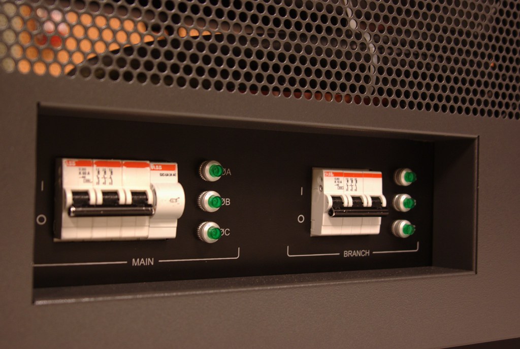
SC5832 Circuit Breakers
Image Credit: “SC5832 Circuit Breakers” by vaxomatic is licensed under CC BY 2.0
DC Circuit BreakerAC Circuit Breaker
The DC circuit breaker uses a thermal protection principle where the overloaded current is slightly larger than that of the standard current for the highly overloaded magnetic protection principle. The AC circuit breaker uses magnetic protection and thermal protection principles. 
DC circuit breakers can be used to protect the main circuit or a single load that uses a DC source. AC circuit breaker is used with a circuit or device that uses an AC source for power. 
As in the DC circuit, the voltage is continuous, and the arc is constant, so it is difficult to disconnect from the circuit. The AC circuit breaker easily gets disconnected from the circuit. 
Extinguishing the arc is relatively poorer than the AC circuit breaker as DC does not have a zero-crossing point. Extinguishing the arc is easy with an AC circuit breaker as ac has a zero-crossing point with every complete cycle. 
The extinguishing device is mainly magnetic blowing typeThe Arc extinguishing device is mainly grid type
AC circuit breaker cannot be used in place of DC circuit breakerDC circuit breaker cannot be used in place of AC circuit breaker as AC voltage or current may have a different effect on the DC circuit breaker
DC circuit breaker needs extra Arc extinguishing measures as DC cannot be self-extinguished. DC needs to be extended, and additional mechanisms such as DC Arc can only be extinguished by cooling or mechanical introduction. In AC Arc, interruption is easy as voltage and currents are not in steady-state, so the AC circuit arc is weaker than the DC circuit arc, so no additional measures are required. 

Transformer Example:Exhaustive List of Examples

The transformer is an appliance that conveys electrical energy from one electrically isolated circuit to other electrically isolated circuit by way of a magnetic field medium without change in the frequency.

This article will discuss the different transformer examples in details.

Transformer Example as follows:

Instrument Transformer

An instrument transformer is a special transformer designed with high accuracy to measure, isolate or transform high-level current or voltage applications in a power system.

The primary winding (or coil) of the instrument transformer is directly linked to the high voltage or high current circuit, whereas the secondary winding (or coil) of the instrument transformer is linked to the instrument or meter.

Instrument Transformers can be classified into two types:

Potential transformer

A potential transformer is a type of instrumentation transformer designed to measure high voltage in a power system while using a standard low range voltmeter.

The primary winding (or coil) of the potential (or voltage) transformer has greater number of turns than that of the secondary winding (or coil), where the secondary winding is linked to a voltmeter. In potential transformer magnetic core with shell-type construction is used for better accuracy.

Application:

  • Used to operate protective devices and relays.
  • Used in synchronizing generators or devices with grid.
  • Used while protecting feeders.
  • Used in long power line carrier communication circuits.
undefined
Image Credit: Instrument Transfromer By Wordtwist – Own work, CC BY-SA 3.0,

Current Transformer

The Current Transformer is an example of a transformer designed to measure a high current in the power system, which can convert the primary current into the required secondary current.

In the current transformer, the primary winding has less number of turns than that of the secondary winding, whereas the wire used in the primary winding is is heavy wire. In contrast, the wire used in the secondary winding is a very fine (or thin) wire.

A low range of ammeter is connected in the secondary winding where the can be treated as short circuit because the internal resistance of the ammeter is negligible relative to the resistance of the secondary winding resulting current transformer is prepared for short circuit condition. Current Transformers secondary winding should not be left open because it can lose its calibration.

Application

  • A current transformer is used for isolation between the measuring instrument and the high voltage power circuits, which ensures the operator’s safety with proper operation.
  • A current transformer is used to measure current, which is very accurate within a specific current range.

Auto Transformer

Auto transformer is an example of a transformer that is predominantly used in applications where low voltage is required.

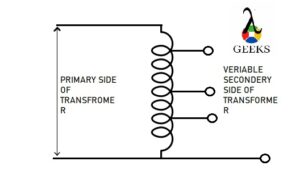
An auto transformer is a transformer that contains only one winding common to both primary and secondary circuits of the transformer.

Advantages of the auto transformer (over two separate winding transformers):

  • Less amount of conductor and core material is required for construction
  • Ohmic loss is reduced
  • An auto transformer has powerful efficiency than two-winding transformers for the exact value of the input.
  • The lower value of leakage impedance
  • An auto transformer is low-priced relative to two winding transformers.

The main disadvantage of an auto transformer is that, unlike two separate winding transformers, here in an auto transformer, direct physical contact between the primary and the secondary circuit is there, which causes to Lost in electrical isolation between two sides. If electrical isolation is not required in the application, then the auto transformer is inexpensive to tie nearly equal voltages together. 

Applications:

Audio frequency Transformer

In the audio frequency span of 20 to 20000 Hz, a tiny iron core transformer is used, which is known as an Audio-frequency transformer.

Audio frequency Transformers can be used for communication, measurement, and control. It can be used in isolation, such as the output speaker being isolated from the input amplifier; in such a case, the primary and secondary winding ratio is 1:1.

 Audio frequency transformer is mainly used for 

  • Impedance Matching.
  • To step up or step down the voltage in the amplifier to obtain the required voltage gain.
  • To increase or decrease the load impedance.

This device can be used as a bidirectional device, such as primary winding can be output winding and input winding, similarly the secondary winding can be operate as input or output winding.

An audio frequency transformer’s complete audio frequency range can be divided into three-part low-frequency, immediate, and high-frequency ranges.

Pulse Transformer

A pulse transformer is a transformer that operates with pulse form of voltage and current this type of transformer is commonly used in digital communication, radar, television, thyristor systems, etc.

The input of the pulse transformer is discontinuous or discrete in nature, where the pulse width can vary. An essential requirement of the transformer is that the input pulse to the primary circuit, after being transferred to the secondary circuit, can be reproduced accurately.

The Transformer analysis in Pulse transformer is carried out by dividing its solution into three parts. The first part gives the response for the front edge of the pulse, the second part gives the response for the flat top of the pulse, and the third part provides a reaction after the termination of the pulse.

The size of the pulse transformer is minimal. As primary and secondary winding have comparatively few turns resulting leakage inductance is minimum.

Rotary Transformer

The rotary transformer is the same as a two separate winding Transformer accept the geometry.

Rotatory Transformer is used to couple electrical signals between primary and secondary winding, which rotates concerning each other with negligible changes in electrical characteristics.

There can be three basic configurations of rotatory transformer: concentric cylindrical Axis configuration, face-to-face or pot core configuration, and the LT core configuration.

Parametric Transformer

Parametric Transformer was first described by Wanlass, et al. in 1968.

The parametric transformer is a special type of transformer that transfers power from primary to secondary without using mutual inductance coupling but by variation of the parameter in its magnetic circuit.

Linear variable differential transformer (LVDT)

The linear variable differential transformer is a class of transformer which is used for measuring position and displacement of an object under observation.

The linear variable differential transformer (LVDT) is an electromechanical instrument that responds to the linear motion (of an object) or position and convert it into a corresponding electrical signal.

Linear Variable Differential Transformer (LVDT) embodied of three coils, one primary coil and two secondary coils. The number of turns in both secondary coils is identical, and both secondary coils are connected in such a way that the output is the difference of voltage between two secondary coils.

undefined
Image Credit: linear variable differential transformer By Wapcaplet, CC BY-SA 3.0,

LVDT (Linear Variable Differential Transformer) is known also as linear variable displacement transformer or differential transformer.

Rotary variable differential transformer (RVDT)

The rotary variable differential transformer (RVDT) is a class of transformer which responds on angular displacement or rotatory motion of an object under observation.

RVDT is similar to LVDT apart from the geometry design. The output of the RVDT is AC current equivalent (or relative) to the angular displacement of the object under observation.

RVDT has one primary coil and two secondary coils same as LVDT. The number of turns in both secondary coils of RVDT is identical. Both secondary coils are linked in such a way that the resulting voltage is the difference in voltage between both secondary coil’s voltage. But the geometric shape of RDVT Cam.

VGA vs HDMI:Exhaustive Comparison and Detailed Facts and FAQs

10983658213 fcaa77dcd0

VGA and HDMI are both display interfaces. Nowadays, HDMI is widely in use, where VGA is used in limited applications as VGA is the oldest display interface. 

This article will discuss the comparison between VGA vs HDMI in a detailed manner.

VGA HDMI Comparison:

VGA is the oldest display interface, and HDMI is one of the latest display interfaces, so lets compare these two technologies:

ParametersHDMIVGA
Stands For High Definition Multimedia Interface Video Graphic Array
Founded in HDMI was introduced at the end of 2002 VGA is the oldest digital interface introduced in 1987
Designed and Introduced byHitachi, Sony, Toshiba, Philips, Silicon Image, Panasonic, and Thomson.IBM
Signal HDMI uses digital signals for communication. HDMI uses digital data signal and VGA uses analog data signal, then transfer or transmission of data is more efficient in HDMI than VGA. and HDMI is easily completable with digital devices VGA uses analog signals for communication. New devices use a digital signal, so for using VGA cable digital to analog and  then analog to digital conversion required.
CompatibilityHDMI is compatible with DVI, VGA, etc, with converter.VGA to DVI and VGA to HDMI converter is also available
Resolution and Refresh rate HDMI with different versions, it can attain 8k (7680 X 4320) resolution with 120Hz refresh rate, but HDMI with 2K resolution it can achieve 480Hz refresh rate. The maximum resolution of a standard VGA is 640 X 480 with a 60 Hz refresh rate. Higher resolution can be attained with different versions of VGA.
ConnectorHDMI has 19 or 29 pins in its connector, there are five different types of connectors in HDMI, such as Type A, Type B, Type C, Type D and Type E.VGA only has 15 pins in the D-SUB connector and VGA BNC connector has a separate connector for each color and sync, such as Red, Blue, Green, Horizontal Sync, and Vertical sync.
Noise or InterferenceHDMI cables are less sensitive to crosstalk but can suffer from interference by electromagnetic fields.VGA cables are easily subjected to crosstalk and interference.
CableVGA cable cannot carry audio, and video signal with one cable, for carrying audio and video two different cables is required. HDMI cables carry Consumer Electronics Control (CEC) which enable user to control HDMI devices with a maximum of 15 devices.HDMI cable carries both video and audio signal through one cable simultaneously .
CostVGA is inexpensive, but converters from VGA to any other signal can cost more than that of a VGA cable.HDMI is relatively costlier than that of a VGA, but converters of HDMI to Other signal is cheaper.
LagHDMI apply post processing on the input signal which causes lag.VGA connections generally exhibit less input lag than HDMI connections because VGA does not apply post-processing on the (input) signal.
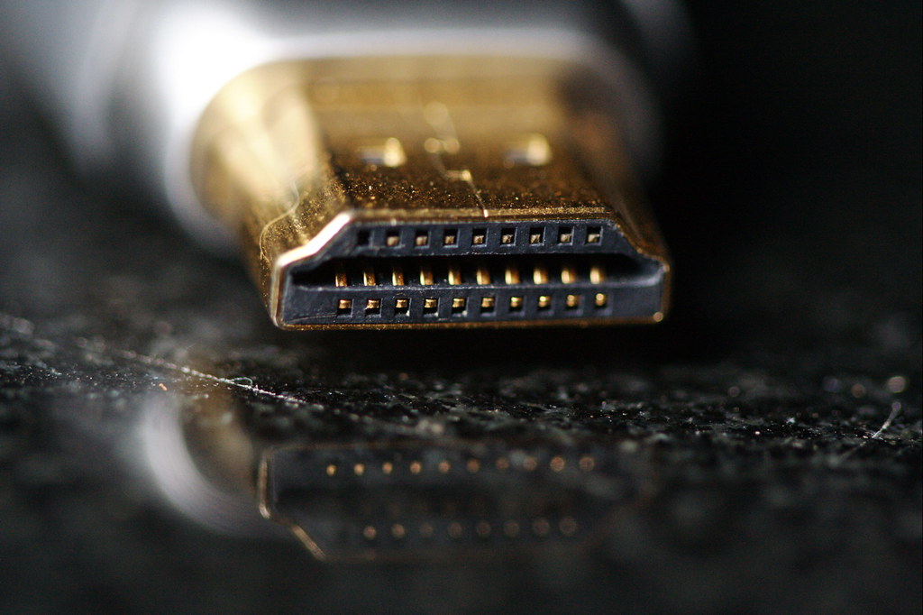
HDMI
Image Credit: “HDMI” by Sam-Cat is licensed under CC BY-ND 2.0

HDMI vs VGA quality

HDMI can transfer eight channels of uncompressed or compressed digital audio simultaneously

The quality of HDMI is better than that of VGA because HDMI uses an uncompressed or compressed digital signal. In contrast, VGA uses an analog signal, which creates a significant difference in quality.

Since HDMI uses an uncompressed connection, HDMI is independent of the various digital standards used by individual devices. It can carry high-quality multi-channel audio data and can carry all standard videos. HDMI is capable of carrying control and Status information in both directions, and as modern devices use digital signals, HDMI is easily compatible with them. HDMI allows managing pixel by pixel the native resolution of the screen with whatever the source devices.

VGA vs HDMI gaming

High-resolution and high refresh rates, all frame rates are required for a quality gaming experience for modern gaming.

The standard VGA is limited to 640 X 480 resolution and refresh rate of 60 Hz, which is not very much suitable with modern gaming standards. In contrast, the maximum resolution HDMI can attain 8K with a 120 Hz refresh rate which is very much ideal for every modern gaming experience.

Although the cables do not limit the refresh rate or resolution, they can be restricted by the source or connectors used. As HDMI is comfortable with digital devices, it is preferred over VGA because VGA Uses an analog interface which seems outdated nowadays. Only limited devices use an analog signal, so if it is not necessary to use VGA, always go for HDMI for gaming.

VGA vs HDMI resolution

HDMI was introduced in 2002 to improve existing connectivity standards by creating more miniature and better connectors which can summon tenuously transmit digital video and audio signals.

The standard VGA 640 X 480 resolution with 60 Hz refresh rate, whereas with a different version of HDMI, it can go up to 8K resolution with 240 refresh rate.

VGA’s maximum resolution can attend up to 2048 X 1536, but VGA does not prefer HDMI for high-resolution.

VGA vs HDMI
Image Credit: “Monitor” by davispuh is licensed under CC BY 2.0

VGA vs HDMI cable

Resolution and refresh rates are not limited to the cable but are determined by the source or device.

The quality of HDMI cables is much better than that of VGA cables, as VGA requires separate cables for audio and video, where HDMI can transfer audio and video simultaneously. HDMI cable is capable of up to 8 compressed or uncompressed digital audio channels, along with Consumer Electronic Control (CEC). 

13w3 to VGA cable
Image Credit: “13w3 to VGA cable” by gctwnl is licensed under CC BY-SA 2.0

The data in the VGA signal is analogous, so loss in data or interference in this type of signal is easy. With an increase in the length of the wire, the quality of the signal decreases. VGA Analogue data signal is also prone to noise and interference. HDMI uses transmission minimized differential signaling (TMPS), which can convert A picture automatically into the most appropriate format such as 16:9 or 4:3.

HDMI cable has16 wires that are wrapped in a single cable and carry a bandwidth of 5gbps. HDMI carries high-quality multi-channel audio data and can carry all standard formate of video. HDMI has three different channels for communication such as Display Data Channel (DDC), Transition-minimized differential signaling (TMDS) and Consumer Electronics Control (CEC).

Does VGA to HDMI reduce quality

VGA to HDMI converter is more expensive than the price of the VGA cable.

As the signal in VGA is analog and signal in HDMI Digital, when the conversion of the signal takes place, some loss of Signal quality happens, which can also introduce noise in the Signal.

During the conversion from VGA to HDMI, the analog signal is converted into a digital signal (using analog to digital converter), and running the VGA signal directly into an HDMI connector can cause damage. The connector as an analog signal has a higher voltage level, so a scaler or converter is required, which will take the VGA analog signal and audio signal to convert them into a digital signal (using digital to analog converter), which can be sent out to HDMI cable for connection.

Why does VGA to HDMI not work

Convert the signal between VGA and HDMI using a converter chip, where the converter chip is either designed to convert a VGA signal to HDMI or HDMI signal to VGA signal.

VGA to HDMI converter is not working causes can be:

  • The problem with the connector or port.
  • The malfunctioning signal from VGA to HDMI.
  • Check the power supply of the converter as VGA to HDMI converter requires external power for processing.
  • Check connection or lose connections.
  • Bad quality display can be caused by incorrect interference with the cable or faulty connector.
  • Restart the device after connecting as VGA is required to restart for better compatibility with the device.
  • New cables can be covered with a plastic cap so remove the plastic cap before using it.

Can VGA do 1080p 144Hz

Nowadays, only the older version of devices uses VGA port; otherwise, the newer ones use DisplayPort or HDMI.

VGA is not recommended for 1080p 144Hz, as it can adequately work till 1080p with a 60 Hz refresh rate, when the refresh rate increases beyond 60 Hz resolution decreases.

Original VGA cable can have a maximum resolution of 640 X 480 with a refresh rate of 60Hz; nowadays, 1080p is possible with VGA. The maximum resolution of VGA can be limited by signal source refresh rate also depends upon the signal source and display different modern connectors can easily achieve 1080p with 144 Hz.

Is HDMI better than VGA for 1080p

HDMI carries a digital signal where VGA has an analog signal that causes a significant difference between both the signals.

HDMI is recommended over for 1080p as VGA carries analog signal where HDMI carries digital in VGA at 1080p refresh rate is limited to 75 Hz at most, whereas with different versions of HDMI 240hz frequency rate can be achieved with 1080p resolution.

Standard VGA has a maximum resolution of up to 640 X 480, but with the latest technology, it is capable of 1080p. Still, the resolution and frequency rate can be limited due to the signal source or display.

Is HDMI sharper than VGA

Currently, HDMI is used with most devices as devices are compatible with digital signals, where is the use of VGA is very much limited.

HDMI has sharp images or videos, then VGA for higher resolution.

HDMI uses a digital interface that is able to carry video and audio 17 easily as HDMI uses digital signal which has many advantages over analog signal practically the difference in image quality is unnoticeable between HDMI and VGA. As VGA uses an analog signal, which can decrease image quality during transmission or conversion of the signal, noise or interference may occur incorrect translation of level may happen, as the length increases, the quality of signal decreases. The difference in quality VGA and HDMI is noticeable for higher resolution.

Can a VGA cable affect screen resolution

Connectors have 15 pins for VGA cable and VGA cables require separate cables for video and audio transmission. The source and quality of the cable can control the resolution of VGA.

Analog signal is not much immune to external noise, flickering, interference, etc. And with an increase in the distance, the quality of the signal degraded, which affects the overall resolution. Using a better quality VGA cable with a covering minimum length as possible may reduce noise and interference.

Do I need both VGA and HDMI?

VGA uses analog interference, whereas HDMI uses digital interference.

Display devices cannot use VGA and HDMI simultaneously, but display devices can change or switch between the cables if required.

Generally, VGA and HDMI are not required simultaneously. VGA is the oldest interface with display. The devices which still use the VGA port are very much limited, where the HDMI port is widely in use.

How can I increase my VGA resolution?

The standard VGA resolution is very much limited; it doesn’t support high-definition images or video.

HDMI to VGA converter or adaptor can be used to get better resolution from the source for a better and sharper image or video for VGA connector.

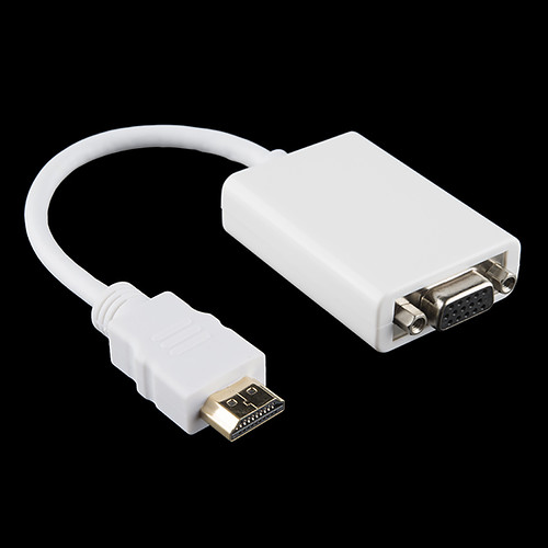
HDMI to VGA Adapter
Image Credit: “HDMI to VGA Adapter” by SparkFunElectronics is licensed under CC BY 2.0

HDMI uses digital signal and can carry both audio and video conversion of HDMI to VGA converter will not improve the quality of the original signal, but for better transmission HDMI cable can be used instead of VGA cables. If Required but with HDMI converter will be needed, which will increase the overall expenditure.

Do monitors need a VGA cable

VGA is the oldest display interface, introduced by IBM in 1987.

Only an older version of monitors or devices have a VGA connector so the VGA cable can only be used for only older monitors or devices.

As VGA cable is much more intensive than other cables, it can be used when the budget is limited but not recommended with converters as the converter is more expensive than that of the VGA cable. If any device has an HDMI port, use an HDMI cable. If any device has a VGA port, then only use a VGA cable because using a converter also reduces the quality of the signal and using a converter increases the overall expenditure.

Does VGA to HDMI adapter work

HDMI adapter is used to convert the analog VGA signal into a digital HDMI signal.

If all the connections are correctly connected to the eye doctor and from the adapter, then the adaptor should work properly if their adapter is not faulty.

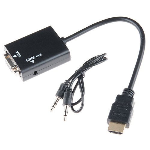
HDMI to VGA Adapter
Image Credit: “HDMI to VGA Adapter” by SparkFunElectronics is licensed under CC BY 2.0

Does VGA affect gaming

VGA uses separate cables for audio and video. It cannot transfer video and audio simultaneously through a single cable.

The slandered version of VGA is limited to 640 X 480 resolution with a 60 Hz refresh rate, which is not suitable for modern gaming standards. With many different versions of VGA, it can extend up to 1080p with a 60 Hz to 75 HZ refresh rate, which can limit the use of VGA in gaming.

VGA can affect the quality and can get interference, on lower quality of VGA cables and the image quality also may get affected. Several devices that produce or use analog signals had different refresh rates with different resolutions, the processor of the device must be able to process it as VGA cable does not limit the resolution or reference rate these are mainly limited by the source, but with higher refresh rate then limit can degrade the image quality.

Does VGA cause lag

More components or converters are connected in the path of the signal, and more lag is added to the signal as every component causes some degree of delay.

VGA has a relatively lower leg than HDMI because the VGA signal does not apply post-processing on the input.

Series Circuit Examples:Complete Insights and FAQs

R s 300x128 1

A series circuit has only one path for electric currents to travel through. In this type of circuit, all the different circuit components are linked in a single branch or path of the circuitry.

This article will discuss in detail different basic series circuit examples such as:

Resistor in Series

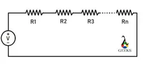
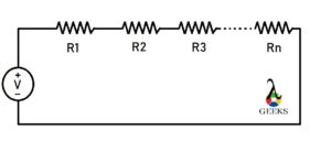
Suppose there is more than one resistor linked in a series circuit combination. In a series combination, the resistor is linked in such a way that the terminal of one resistor is connected to the terminal of the following resistor resulting in only one path for current to flow through.

The value of resistance increases with the increasing number of resistors in series combination. The current magnitude through each resistor remains constant, where is the voltage or potential drop across each resistor depends upon the magnitude resistance of each resistor.

If the resistors linked in the series are of identical values, then the potential drop across individual resistors will be identical, as the current flowing across each resistor is the same.

The equivalent resistance represents the overall resistance effect of the resistors in the series combination.

series circuit examples
Fig. Series combination of ‘n’ resistors.

Capacitors in Series

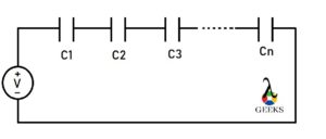
Suppose there is more than one capacitor connected in such a way that the terminal of one capacitor is linked to the terminal of the following capacitor resulting in only one path for current to flow.

The overall capacitance decreases as the number of capacitors increases in a series combination.

C s
Fig. Series combination of ‘n’ Capacitors.

As the current magnitude through each capacitor is the same, the charge stored by each capacitor will be the same regardless of the value of the capacitor’s capacitance. At the same time, the potential drop across each capacitor will depend upon the value of each capacitor’s capacitance.

Inductor in Series

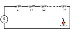
Suppose there is more than one inductor connected in a series combination such a way that one terminal of the inductor is connected to another terminal of the inductor resulting in only one path for current to flow.

The voltage or potential drop across individual inductors is not equal, whereas the current flowing through individual inductors is identical in the series combination.

L s
Fig. Series combination of ‘n’ inductor.

The total or equivalent inductance is the summation of the individual inductance of each inductor connected in series as the number of turns of coils increases with the addition of the inductor.

Resistor and Capacitor in series

Resistor and capacitor can also be linked in a series combination with each other.

If there is at least one resistor and one capacitor connected in series with each other, then the resulting circuit will be first-order circuitry.

The overall importance of the RC series circuit

gif 5

Where is Z is the overall impedance

R is the resistance of the resistor

XC is the impedance of the capacitor

The phase angle of the RC series circuit is

gif 1
File:AC RC series circuit.svg
Image Credit: “File:AC RC series circuit.svg” by P1ayer is marked with CC0 1.0

In this RC series circuit, the overall voltage lags current, the angle between voltage and current depends upon the value of resistance and the impedance generated by the capacitor.

Resistance and Inductor in series

The resistor and inductor can also be connected in a series combination with each other.

When there is only one resistor and one inductor in the circuitry, it is the first-order RL circuit.

The overall impedance of the RL series circuit is

gif 2

Where R is the resistance of the resistor

And XL is the impedance generated by the inductor.

The phase angle of the RL series circuit is equal to

gif 3

The overall voltage leads to current in the RL series circuit, and the angle between the voltage and current depends on the value of the resistance and impedance generated by the overall circuitry.

RLC (Resistance, Inductor and Capacitor) Series 

In an RLC series circuit, at least one resistor, one capacitor, and one inductor are connected in series combination with each other.

The current across each circuit element in the series combination is the same. Still, the total or overall voltage is split across each component’s voltage magnitude depending upon each component’s electrical characteristics.

RLC series is a resonant circuit that resonates at a specific frequency which is called the resonance frequency.

If the inductor impedance is greater than that of the capacitor’s impedance, then the overall circuit voltage leads to current. If the capacitor impedance is greater than the impedance of the inductor, then the overall circuit voltage lags current by some angle. In both cases, the angle value depends on the resistance and impedance generated by the inductor and capacitor.

The overall impedance of RLC series circuit :

gif 4

The phase angle of the RLC series circuit is equal to

gif 5

LC  (inductor and capacitor) Series

Pure inductor and capacitor can be connected in a series combination. There must be at least one inductor and one capacitor in this combination.

As both the elements are connected in series with each other, the current flowing through each element will be the same, and the overall voltage will be simply the summation of the voltage drop across the capacitor and the inductor.

The total (or overall) impedance of the circuitry is the summation of the impedance of capacitor and inductor in the LC (inductor and capacitor) series circuit.

The overall impedance Z = ZL+ ZC

where

gif 7

then

gif 6
File:Tuned circuit animation 3.gif
Image Credit: “File:Tuned circuit animation 3.gif” by Chetvorno is marked with CC0 1.0

Voltage in Series

The current source cannot be combined in a series but can be combined in parallel as the series combination of current sources violates Kirchhoff’s current law.

For example, two voltage sources are linked in a series combination. When the voltage source’s positive terminal is linked together with the negative terminals of the voltage source, the overall voltage combination will be added.

In contrast, when the positive terminal of the voltage source is connected to the negative terminal of another voltage source, then the combination’s overall voltage will subtract from each other; this is based on the sign convention of the voltage source or the direction of the flowing current in the circuitry.

If there is more than one current source connected between two circuit nodes, then the current source is in parallel combination.

FAQ:

Why do we connect circuit in series

The series circuit can be a combination of different circuit elements such as resistance, capacitor, inductor, etc.

When the constant current is required, the series combination is used as the current’s magnitude remains consistent in the series combination, which can be controlled or changed easily.

How does voltage changes in a series circuit

Series circuit is also known as a voltage divider circuit as the overall potential energy gets split into all circuit components.

As the current throughout the series circuit is constant, the value of voltage depends upon the impedance or resistance generated by each circuit element connected in the series combination. That is how the value of voltage changes with the electrical property of each component.

What is the advantage of series circuit?

There are several advantages and disadvantages of a series circuit combination depending on the application or where it is used.

The components connected in a series combination have the same magnitude of current flowing through it. All the components connected in series can be turned on or off by using only one switch. The circuit combination does not get overheated easily, and the circuitry design is very simple relative to the parallel circuit.

9 Examples Of Parallel Circuit

R P 300x179 1

A parallel circuit equips current to travel through different (distinct) or branches of the circuit. The current across paths can be distinct, but the voltage across each parallel path is identical.
A circuit can be a parallel circuit or series circuit, or a combination of parallel and series circuits. There are several different parallel circuit examples.

Some of the examples are listed below

Resistors in Parallel

Suppose there is more than one resistor connected between two circuitry nodes, then the resistors are connected in parallel with each other. In other words, when both the terminal of the resistors are connected respectively to each end of the other resistors. The value of resistance can be different or identical in parallel circuit combinations as a requirement. The voltage (or potential difference) over each resistor is identical in parallel combination as there is a variety of paths for current to flow. The value of current will vary with resistance in each path. If the value of resistance of each path is identical, then the current flow through each part will also become identical.

For example, if two resistors of the same resistance are connected in parallel with each other, then the current flowing through them will be the same. With Current Division rules the current into and out of each path of the circuit can be determined.

But when two resistors, R1 and R2, of different resistance, are connected in parallel, the current flowing through them will differ. As V=IR (Ohm’s Law) as V is the same for all parallel circuit components, the value of I depends on the value of R.

The whole parallel circuitry of the resistor can be replaced by a sole resistor of the value equal to the equivalent resistance of the overall parallel combination of the resistors.

The equivalent resistance represents the overall resistance effect of all the resistors connected in parallel.

Equation of equivalent resistance in parallel combination with resistor:

ezgif 2 ad641f5235

Where Re -> Equivalent resistance.

R1, R2, R3 … Rn -> Different resistance connected in parallel. 

When two resistors (R) in parallel are of the same value, the equivalent resistance of both resistors is half of the one resistor (R).

ezgif 2 0720f69d42

The resulting equivalent resistance of the resistor in parallel is always lower than the individual resistor, and as more resistance is added, the equivalent resistance decreases.

Capacitor in Parallel

Suppose there is more than one capacitor connected between two nodes of a circuit, then the capacitors are in parallel combination with each other. in other words, when both the terminals of the capacitor are connected respectively to each and other capacitors.

When capacitors are linked in parallel, the resulting capacitance (or total capacitance) equals the addition (or sum) of each capacitor’s capacitance in the combination.

Ct = C1 + C2+ C3 …..+ Cn

Where Ct-> total capacitance of the parallel combination.

C1, C2, C3 … Cn -> different capacitor connected in parallel.

cp
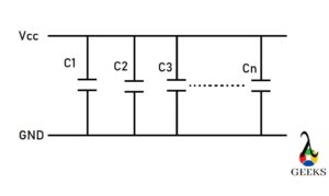
Fig. Parallel circuit of Capacitors.

The voltage across each capacitor in parallel combination is the same, but the charge stored by each capacitor depends upon the value of capacitance of each capacitor, according to Q=CV. So as the capacitance of the capacitor varies, the stored charge will also change as the applied voltage across all the capacitors in parallel combination is identical.

For example, if three capacitors are linked in parallel, the capacitance of every piece capacitor can be distinct or identical. Suppose every capacitor connected in parallel is of exact capacitance. In that case, the charge stored by each capacitor will be the same, but if the capacitance of each capacitor is different, each capacitor will hold a different amount of charge. The total charge (Q) stored by the overall capacitor (in parallel combination) is the sum of individual charges.

Q = Q1 + Q2+ Q3

Where Q1, Q2, Q3 is the charge stored by the capacitor C1, C2, C3 respectively.

As we know Q= CV

So, Ct = C1V + C2V+ C3V

Ct = C1 + C2+ C3

Inductor in Parallel

Suppose there is more than one inductor connected between two nodes of a circuit, then the inductor is connected in parallel combination with each other. In other words, when both ends (or terminals) of the inductor are connected respectively to each and of the other inductor.

The current flow through each inductor is not equal to the overall current but is the summation of each current passing through each inductor connected in parallel. The inductance of a parallel combination of the inductor is lesser than that of the combined inductance.

l P
Fig. Parallel circuit of Inductor.

The total current flowing through the overall parallel combination is the sum total of individual currents flowing through each conductor so

lt = l1 + l2+ l3 …..+ ln

Where I is the overall current, and l1, l2, l3 … ln is the current through the L1, L2, L3 … Ln.

The relationship of current, voltage, and inductance of an inductor can be defined as V= L (di/dt)

As

ezgif 2 57911769de
ezgif 2 a652fe412a 1
ezgif 2 76d736b031
ezgif 2 9de77b0146

Where Lt => overall inductance of the parallel combination of inductors.

L1, L2, L3 … Ln are the individual inductors in the parallel combination.

The above equation holds when there is no natural inductance or magnetic coupling between any inductors.

Resistor and Capacitor in Parallel

If there is at least one resistance and one capacitor connected between two circuit nodes, then the resistor and capacitor are connected in a parallel combination.

When resistor and capacitor are in parallel combination, the overall impedance will be at a phase angle between 0 degrees to – 90 degrees, and current will have a phase angle between 0 degrees to 90 degrees.

In a parallel combination of resistor and capacitor, the parallel circuit components share the same voltage. The phase angle depends on the value of the current that passes (or flow) through the capacitor and the resistor. If the current through the capacitor is higher, the phase angle will be close to 90 degrees. If the current through the resistor is greater than the phase angle, it will be close to 0 degrees.

Overall impedance

ezgif 5 ba601f553a

Where Xc -> impedance of capacitor.

R -> resistance of the resistor.

Phase angle

ezgif 5 7ea7ef5e63

IC -> current through capacitor.

IR -> current through the resistor.

If the RC parallel circuit consists of only one capacitor and one resistor, then the circuit is of first-order type.

Resistor and Inductor in Parallel

If at least one inductor and resistor are connected between two circuit nodes, then the inductor and the resistor are in a parallel combination. The overall phase angle of this combination is always lying between 0 degrees to -90 degrees. The value of the phase angle depends upon the value of the current into and out of the inductor and the resistor. If the current through the inductor is more than that of the resistor, then the angle will be close to -90 degrees, and if the current through the resistor is more than the phase angle will be close to zero degrees. 

 The overall impedance (Z) is

ezgif 5 f4b3263f57

Phase angle

ezgif 5 8a0c823ac4

Where R and L are the resistance and inductance of resistor and inductor, respectively.

IL and IR are the currents through the inductor and resistor, respectively. 

If the LR circuit is composed of only one inductor and one resistor, then the circuit is the first-order LR circuit.

Parallel combination of Resistor, Inductor and Capacitor

If the resistor-capacitor and inductor are connected between two nodes of a circuit, then this is the parallel combination of resistor-capacitor and inductor

The voltage across each element is the same, but the total current flowing through this combination gets divided across each component depending upon the importance of each element

This RLC in parallel combination circuit is a resonating circuit.. When the overall current through the circuit is in phase with the applied voltage, it resonates at a particular frequency called resonating frequency.

By using phasor diagram: IS2 = IR2 + (IL2 – IC2)

Where IL -> current through the inductor.

IC -> current through the capacitor.

IR -> current through the resistor.

IS -> current through the overall circuit.

Inductor and capacitor in parallel

If at least one inductor and a capacitor are connected between two circuit nodes, then the inductor and capacitor are in a parallel combination. The LC parallel circuit is in resonance when the capacitor’s impedance is equal to the inductor’s impedance. At that time, they cancel out each other to provide a minimum current in the circuit, whereas the overall impedance of the circuit is maximum.

Resonating frequency

ezgif 5 c2ec35c3e1

Overall impedance

ezgif 5 adb6432021

Where L and C are the inductance and capacitance of inductor and capacitor, respectively. 

XL and XC are the impedance of the inductor and capacitor, respectively.

When XL > XC, then the overall circuit is inductive.

XC> XL, then the overall circuit is capacitive.

XC = XL then the circuit has maximum impedance and minimum current, and this circuit is called the rejector circuit.

Diodes in parallel

If more than one diode is connected between two nodes of a circuit, then the diodes are in parallel combination with each other.

The diode having a low forward voltage drop across it will carry a more significant amount of current than other my connected diode invalid the overall current capacity of the circuit will increase.

The forward voltage drop over (or across) the diode can vary with diode types. It is not necessary to connect all the diode in forward or reverse biased combination in parallel diode combination only. It can be a combination of both forward and reverse biased diode as for the requirement. The current sharing by each diode depends on its electrical capacity.

For example, in a parallel combination of the diode, if one diode is connected in forward biased and another is in reverse biased, then the current will flow through the forward biased diode as a reverse biased diode will block the current.

Transistor in parallel

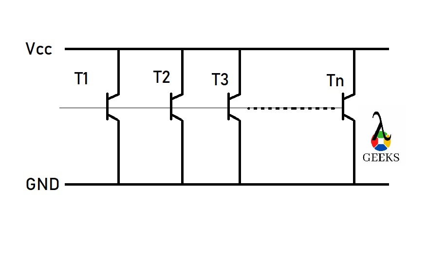
When the identical pinout of two or more transistors is linked together in circuitry, this is the parallel combination of transistors.

The parallel combination of the transistor increases the current holding capacity overall. As several transistors increase, the current holding capacity of the overall circuit also increases. Generally, one transistor is sufficient for producing a moderate output current, but when a higher output current is required, adding more transistors in parallel becomes necessary.

t p
Fig. Parallel circuit of Transistor.

Current source in parallel

The current source cannot be combined in a series but can be combined in parallel as the series combination of current sources violates Kirchhoff’s current law. If there is more than one current source connected between two circuit nodes, then the current source is in parallel combination.

For example, two current sources are connected in parallel combination, when the current source’s positive terminal is linked together and negative terminals of the current source is connected, then The current overall combination will get added. In contrast, when the positive terminal of the current source is connected to the negative terminal of another current source, then the overall current through the combination will get subtracted from each other. This is based on the sign convention of the current source or the direction of the flowing current in the circuitry.

FAQ:

What is a parallel circuit?

There can be different types of circuits, where the parallel circuit is one type of circuit.

In a circuit where the current has more than one path or branch (between two circuit nodes) to travel through, different circuit elements are connected in different branches of the circuit.

What is the main disadvantage of parallel circuits?

There are a variety of advantages and disadvantages of a parallel circuit combination depending upon the application and uses.

In a Parallel circuit, the need of wire in parallel combination is more than that of a series circuit; it is the most significant disadvantage of a parallel circuit.

Why do we connect household appliances in parallel?

The House wiring is in parallel combination, and all the appliances are linked in parallel.

When the appliance is connected in parallel, all the appliances get the same voltage for operation. In parallel combination, the resistance is low. If one appliance is at fault, then the other appliance’s operation will not get affected in parallel combination.

Can you have two voltage sources in parallel?

Any voltage source (with distinct or similar value) can be linked in series with each other.

Two Voltage sources having different potential differences cannot be connected directly in parallel as it can violate Kirchhoff’s Voltage Law. Only voltage sources of the same potential difference can be connected in parallel with each other.

What is XL and XC in RLC circuit?

RLC circuit is a circuit in which resistance, capacitor, and inductor can be connected in parallel, series, or other combinations.

XL and XC are the impedance of the inductor and capacitor of the RLC circuit, respectively.

Start Capacitor Vs Run Capacitor: 3 Important Facts

4791854504 3c7ed01282 300x225 1

Start capacitor and run capacitor, both are motor capacitor, both are used for different purpose in the motor operation. Construction of both the capacitor is same, let’s discuss Start Capacitor vs Run Capacitor.

Start CapacitorRun Capacitor
They are used for starting the motor. They are used for providing continuous power to the motor. 
Small duty cycle.Long duty cycle.
Higher Capacitance rating (70-120 micro Farad)Lower Capacitance rating (7-70 micro Farad)
Remain connected to the circuit for short period of time.Remain connected to the circuit for long period of time.
The start capacitor is used during the startup phase of the motor and gets disconnected from the circuit when the motor reaches its predetermined speed, which is 75% of the maximum speed of the motor. Run Capacitor stays directly linked with the auxiliary coil even after the starting capacitor is disconnected (or deactivated) from the circuitry. The run capacitor remains constantly charged while providing a controlled contiguous (or continuous) power to the motor. 

Can I use a Run Capacitor as a start capacitor?

The purpose of starting capacitor is to lag the current in a gallery winding during the starting operation of the motor, and it gets disconnected from the circuit when the router reaches its predetermined speed.

The run capacitor can be operated as a start capacitor, whereas the start cannot be implement as a Run capacitor. To start the motor or develop high torque across the motor, a high capacitance value is required to show the run capacitor array (two or more capacitors are connected in cascade) can be connected.

The capacitor value of the run capacitor is very much smaller than that of the start capacitor; a single running capacitor will not be able to start the motor as it cannot provide enough torque to the motor. There won’t be any problem (or drawback) with the run capacitor to start the motor, but the starting (or beginning) character may not be up to mark, and the motor may take a higher(or intense) starting current with lower torque.

What happens when a Run Capacitor goes bad ?

Capacitor failure can be of two types. Catastrophic failure is generally caused by the motor starting circuit being engaged for too long. The top of the starting capacitor has been blown off, and the inside has been slightly or fully ejected. The capacitor may be just raptured pressure relief blister.

The motor can display various problems if a run capacitor fails, including not starting vibrating, overheating, slow start, or motor buzzing. The motor will not have an uniform electric field that will cause the router(or root) to hesitate at irregular spots. A bad Run capacitor will cause the motor to become noisy, have high energy consumption, drop performance, overheating, etc.

What is the purpose of a Starting Capacitor ?

The start capacitor is come up with in auxiliary (or start) windings of the motor. The capacitance of a start capacitor is much elevated than that of a run capacitor.

The objective of the start capacitor is to provide enough torque to start (or energize) the motor, and it gets disconnected (or deactivated) from the circuit after the motor reaches a predetermined  (or predestined) speed. Without a start capacitor when the voltage has applied to motor, the motor will generate (or give rise to) a humming sound. The capacitance range of a start capacitor is between 70 to 120 micro Farad.

8583976219 924ef1f5b8 b 1
Image Credit: “Inside of a capacitor” by Razor512 is licensed under CC BY 2.0

Start capacitor increases motor starting torque and allows the motor to be cycled off and on rapidly. The start capacitor is designed in such a way that it is used just for a small time period. They can’t stay energized for longer.

How to tell AC capacitor is bad ?

AC capacitor is an integral part(or component) of an outdoor condensing unit of an air conditioner(or AC) or heat pump. AC capacitor provides sufficient power to the motor, which steers the air conditioning system.

Sign of bad AC capacitor:

  • Smoke or burning smell from the exterior air conditioner component
  • Air conditioning is not bring about cold air even after a long time of operation
  • Humming noise from the air conditioner
  • Old HVAC system
  • AC terms off on its own or on random
  • AC doesn’t start working immediately after turning on
  • High energy consumption causes high energy bills without expectation

Effect of failed AC capacitor:

  • Overheated system circuit
  • Short-circuiting in the AC (or cooling system).
  • Power Rushes or Surges.
  • Electrical discharge or Lightning strikes.
  • Intensely peak outdoor temperature

How Does A Transformer Work: 9 Answers You Should Know

TRANS 300x156 1

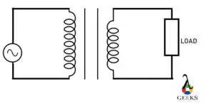
The transformer is a device that contains magnetically coupled coils that are generally electrically isolated from each other—a transformer transfers electrical power from one circuit to another. How does a transformer work? this article s going to take you ride with transformer.

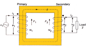
The fundamental principle a transformer work on is the electromagnetic induction (or mutual inductance), when two different electrically isolated coils are in close proximity such that one’s magnetic field can link to another when an alternating current is applied to the primary coil, a fluctuating magnetic field is generated which causes electromotive force in the secondary coil.

How does a step up transformer work?

640px Ideal transformer representation
Image Credit: Electrical Classroom, CC BY 4.0 , via Wikimedia Commons

The transformer which generates a higher voltage across the secondary than the applied voltage to the primary is the Step Up Transformer.

The transformer uses mutual induction (fundamental principle) between two circuits coupled by a common (fluctuating) magnetic flux. When alternating current (AC) is applied to the primary coil, a fluctuating magnetic field is generated, which causes electromotive force in the secondary coil.

How Does A Transformer Work
Fig. Step-up transformer circuit.

As the number of turns in the secondary coil (n2) of the (step up transformer) is greater than the primary coil (n1), the EMF(electromotive force) is corresponding to the number of turns. Hence, the secondary cal generates a higher voltage relative to the primary coil.

The voltage transformation ratio (K) of a step-up Transformer is greater than 1 (K>1).

K= E2/E1= N2/N1

Where K means voltage transformation ration, N1 means number of turns in primary coil,N2 means number of turn in secondary coil.

How does a step down transformer work?

A step-down(one type of substation transformer) transformer generates a lower voltage on the secondary side of the transformer.

A step-down transformer works on mutual induction between two circuits that are electrically isolated from each other while coupled through the magnetic flux. When an alternating current (AC) passes through the primary coil, a fluctuating magnetic field is generated, which causes electromotive force (emf) in the secondary coil.

 As the number of turns in the primary coil(n1) is greater than that of the secondary coil(n2) i.e.  n1>n2, is induced electromotive force(emf) is proportional to the number of turns resulting in the voltage generated across the secondary coil(of transformer) is lower than that of the primary voltage.

TRANS
Fig. Step-Down Transformer circuit.

The voltage transformation ratio (K) of a step down transformer is less than 1 (K<1).

How does Auto transformer works?

The transformer whose (primary and secondary coil windings) are interconnected electrically is the autotransformer which means it has a single continuous winding common to both primary and secondary sides of the transformer.

Autotransformer works on the principle of Faraday’s law of electromagnetic induction (or mutual induction). When the primary coil is connected to an AC supply due to Faraday’s law of electromagnetic induction is an electromotive force (EMF) is generated in the primary coil. As in autotransformers, the primary and secondary coils are in the single continuous winding.

EMF will be developed as the voltage ratio per turn remains the same in both the winding. The secondary voltage generated will be proportional to the number of turns connected to the transformer’s secondary side.

AUTO
Fig. Autotransformer circuit.

A direct electrical connection between windings (primary and secondary coils) ensures that a part of the energy is transferred through conduction between the primary and secondary winding of the transformer. The amount of winding that is shared by both the primary and secondary sides of the transformer(or of autotransformer) is referred to as the common sector. One end of the winding is linked between the supply and load, while the other end of supply (AC Supply) and load is linked to tabs along the winding.

An autotransformer can be a step down transformer when the AC supply is connected across the transformer winding. The load is connected by a tab across a relatively more minor portion of the winding.

How does a transformer work on the DC current?

The transformer is an electrical device that uses magnetic coupling (mutual induction) to pass an AC signal from one circuit to another.

DC current cannot pass through a transformer as for working of transformer AC supply is required, without AC supply there will be no fluctuating magnetic flux. Only a flyback transformer can be excited using a DC source.

How does a microwave transformer work?

Microwave transformers are robust, cheap, and generate high voltage arcs.

Microwave Transformer works on the principle of mutual induction, like other Transformers.

The microwave (oven) Transformer has three (1 primary and 2 secondary) windings. When electricity passes through the magnetron, electrons are influcenced to create microwave radiation. When the magnetron of the microwave (oven) transformer works, AC flow through the secondary winding (or coil) of the (microwave) transformer resulting in the iron core generates magnetic saturation; as the anode voltage of the magnetron shoot up. Anode current also increases along with an increase in current through the secondary winding, strengthening the magnetic separation and increasing the leakage magnetic flux resulting in the transformer generating High Secondary voltage.

How does an output transformer work?

Output Transformer blocks DC and its let AC signal to pass-through.

The output transformer is an electromagnetic device that works on the principle of Faraday’s law of electromagnetic induction, which isolates the input circuit from the output traffic while filtering AC signal to pass through magnetic coupling between input and output circuit.

The Output Transformer can be used to increase or decrease the applied voltage through the input circuit to the output circuit.

How does an optical current transformer work

An optical current transformer is a sensor that is used to measure electric current directly or indirectly.Optical current transformer working can be based on principles such as the Faraday effect, interferometric principle, the micromechanical sensor with optical readout, Bragg Grating. 

The magnetic optical current transformer (MOCT) uses Faraday’s effect (fundamental principal) to measure electric current; it measures the rotational angle of the polarized light under the influence of a magnetic field and converts it into a signal of voltage proportional (or corresponding) to the electric current.

According to Faraday effect the orientation (or inclination) of linearly polarized light under the impact of a magnetic field. When the light propagates (or travel) through a piece of glasses, the rotation angle is corresponding (or proportional) to the strength of the magnetic field component. Polarizer material is used to convert light into a linearly polarized light.

Polarized light passes through an optical rotator because of Faraday’s effect on the orientation of linearly polarized light rotates as it passes through the rotator material. Different polarization material is used as an analyzer that converts the amount of rotation of the polarized light into the corresponding amount of light intensity. This intensity-modulated light travels to the photodiode, which bring about the corresponding electrical signal.

How does flyback transformer

The flyback transformer (generates saw-tooth signal) is also recognized as a line output transformer. This transformer can be excited by using DC volt. It can transfer as well as store energy.

The basic working principle of the flyback transformer is mutual induction. In this Transformer, one diode is linked in series with the secondary coil of the (fundamental) transformer and one capacitor in parallel with the load.

FLYBACK
Fig. Flyback transformer circuit.
  • The primary coil is connected to a DC supply along with the switch. When the switch is on, the (DC) current flows through the primary circuit of the transformer and excites the primary coil. The primary coil ramp(a steadily rise in voltage) is generated through primary inductance, which got stored in the form of magnetic energy between the inductive gap (between coils) of the transformer. A diode is connected in series with a secondary coil of the transformer, which is in Reverse bias that restricts the formation of current in the secondary circuit.
  • When the switch is off, the primary current falls down to zero, and stored energy in the gap is released and transferred to the secondary coil, resulting in a rapid rise of output voltage as the voltage shifts to forward bias.

How does a buck-boost transformer work?

Buck Boost Transformers is used to adjust voltage levels, and it can be used to make small changes to the applied voltage, which can be up to 30%.

A buck-boost transformer has four windings which can be connected in different ways as requirements. It was on the principle of mutual induction between magnetically coupled coils. The resulting (output) voltage of the buck-boost transformer is the function of input voltage. If input voltage varies, then the output voltage will change in the same percentage. This transformer can be step up or step down depending upon its connection between the coils.