Aerobic Septic System Diagram: Detailed Explanations:

800px Greywater septic tank outlet 3255728552 300x225 1

In this article “Aerobic septic system diagram” and aerobic septic system diagram related others facts will be discuss. Aerobic septic system diagram actually use components which are related to mechanical.

The aerobic septic system diagram is another form name is aerobic treatment system. In aerobic septic system a very small size sewage treatment system is work. It is almost same as septic tank system. In aerobic septic system mainly mechanical materials are used to treat discharge or sewage to an absorption area.

Read more about How Does A Heat Pump Work In Winter : Complete Insights, Critical FAQs

Septic pump system diagram:

Septic pump is systems contain a chamber which is placed in underground. It is made with fibreglass, concrete, plastic. In the chamber of septic pump system domestic sewage can flow for treatment.

Septic pump system diagram is given below,

Aerobic septic system diagram
Image – Aerobic septic system; Image Credit – Wikimedia Commons
Schematic of a septic tank 2
Image – Septic tank system;
Image Credit – Wikipedia

Aerobic vs. anaerobic septic system:

The major difference aerobic vs. anaerobic septic system is discuss below,

ParameterAerobic septic systemAnaerobic septic system
By productAerobic septic system produce 1.Water
2. Excess amount of biomass
3. Carbon dioxide
Anaerobic septic system produce,
1. Excess amount of biomass
2. Carbon dioxide
3. Methane
Capital costNot too highHigh
Maintenance costExpensiveNot too much expensive
Typical technologies1. Moving bed bioreactor
2. Activated sludge
3. Extended aeration
4. Tricking filters
5. DHS(Down flow hanging sponge)
6. Oxidation ditch
7. MBR(Membrane bioreactor )
1. Hybrid high rate reactor
2. Single stage UASB reactor
3. Two stage UASB reactor
4. Continuously stirred tank reactor
5. Continuously stirred tank up flow
6. Continuously stirred tank digester  
EnergyHigh energy needed.Low energy needed.
Volume of sludgeLargeLow
Hydraulic retention timeHighLow
Operation  EasyNot easy  
Structure  SimpleComplex
ProcessIn the
aerobic septic system bacteria continuously supplied into the tank where oxygen is also present. The continuous flow of oxygen helps to keep the bacteria more effective and the treatment process can flow continuously. A movable pallet is placed in the tank thus wastewater can avoid splitting into different three layers. This process is easier to treatment wastewater.
In the system tank of the anaerobic two components are placed, one is treatment tank and another is seepage field. At first wastewater is delivering to the treatment tank. In the Treatment tank solid type waste is store in the bottom of the portion. In the top portion slag is placed and in the center of the tank waste water is placed. The wastewater is clean for this reason the water can flow by the pipes which are hidden placed into the leach area. Divider box is situated in the pipes.  From the tank the wastewater flows more fluently. Before the step of filtration treated wastewater is back to the surrounding takes place at the point of leaching.
Effectiveness MoreLess

Frequent asked question:-

Question: – Write the positive sides of Aerobic septic system diagram.

Solution: – The positive sides of Aerobic septic system diagram is listed below,

  1. Aerobic septic system reduce nitrogen
  2. Helps to decreasing drain field clogging
  3. Aerobic septic system perfect for water conservation
  4. Long life is high
  5. Continuously produce high quality wastewater
  6. Aerobic septic system produces clean effluent
  7. Aerobic septic system takes very less amount space for installation
  8. Aerobic septic system can establish in various types of soils
  9. Environmental friendly
  10. Maintenance is very low
  11. Simple design

Question: – Write the negative sides of Aerobic septic system diagram.

Solution: – The negative sides of Aerobic septic system diagram is listed below,

  1. The noise of the blower is too much excessive
  2. Installation cost is high
  3. More power draws
  4. Bad odour can comes if vented is not done properly
  5. Excessive amount of water is use in the Aerobic septic system
  6. Sometimes ammonia is emitted which could causes pollution in the nature.
  7. Aerobic septic system should be insulated neither in winter unfavorable condition will be appear
  8. High amount electricity is essential
  9. Frequent pumping needed
  10. Need more inspection

Question: – Describe the classifications of septic tank system.

Solution: – The size, shape, design can widely changes due to classified the septic tank system. The size factor of septic tank system included soil type, lot size, water bodies, weather condition and many more.

The classifications of septic tank system is listed below,

Mound system:-

The most common classifications of septic tank system are Mound system. In the mound system tank is commonly used in high groundwater, soil depth and shallow bedrock. The mound system tank is made with sand and contained a drain field trench.

Wastewater is flow from septic tank to pump chamber. In the tank wastewater is pumped to the mound system that it could prescribed doses. After treatment of wastewater the water is discharge from the trench. After discharging the water is filter by sand and finally into the soil the water is disperses.

The mound septic tank system need periodic maintenance and a large amount space to install.

Septic tank:

The septic tank contained two chamber and these chambers are made of brick or concrete. PVC, pre or fibreglass septic tank, fabricated concrete rings is also available that will be less expensive.

The septic tank is small size scale decentralised treatment. The septic tank is actually a sedimentation tank and it is available in cylindrical or rectangular shape.

Advantages of septic tank:

  • Electrical energy is not essential
  • Little space required
  • Low operating cost
  • Long service life
  • Simple construction

Disadvantages of septic tank:

  • Only appropriate for low density housing
  • Low reduction in solids, pathogens and organics
  • Manual cleaning

Chamber system:

The chamber system type septic tank has series of chamber which are connected to each other. The chamber system septic tank area and its surrounding is filled with soil.

The chamber system septic tank has many types such as fabric wrapped pipe, open bottom chamber and many more.

Aerobic treatment unit:

Aerobic treatment unit is a natural process by which wastewater is treated. Oxygen rich bacterial is work for treatment in wastewater. For this process not too much space is needed and easy to construct.

Aerobic treatment unit process is done in four stages,

  • Pre treatment
  • Aeration chamber
  • Disinfection
  • Final treatment disposal

Conventional system:

In the conventional septic tank system which is used for very small size household or small business. The conventional septic tanks contain a septic tank and a bed subsurface or trench subsurface wastewater drain field system.

Drip distribution system:

Drip distribution septic tank system is used in many verities of drain fields. In the drip distribution septic tank system very large amount mound of soil is not needed.

This type of system maintenance cost is too high and electrical energy is needed.

Constructed wetland system:

The constructed wetland system treatment process is appearing in natural wetlands. This type of system can work in the pressure distribution or gravity flow.

Recirculating sand filter system:

Recirculating sand filter system is systems that can be construct both in below or above the ground. This type of system is very expensive to maintain and to install. Recirculating sand filter system is very high level treatment process system.

Evapotranspiration system:

Unique drain field type is evapotranspiration system. It is only useful for the specific environmental condition. The weather must be adequate sunlight and heat and must be arid.

Community/Cluster system:

Community/Cluster system the wastewater is collect from two or more than two buildings. This type of system mainly present in rural areas. Its contraction is not too much complicated.
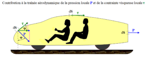
Pressure Drag: What, How, Working, Formula, Examples:

pressure drag 300x116 1

In this article very interring topic “Pressure drag” is discusses. The cause of the pressure drag is pressure comparison intermediate surface of a matter. Pressure drag related everything is prate here.

Pressure drag derive as, when the molecules of the air being more pushed to each other on the surface of the matter’s front face and space is out more than the usual to the back face of the surface matter. The condition for a matter pressure drag more happened in the air particles for the flow of the turbulent.

What is pressure drag?

The relation between the velocity and pressure drag is directly proportional to each other. For the lower amount of velocity the amount of pressure drag is low and for the higher velocity pressure drag is high.

In a matter when force is acting that time the motion of the matter can stand against that known as pressure drag. When the matter is actually a gaseous matter is known as Air resistance or Aerodynamic drag and as the same time when the matter is actually a liquid matter is known as Hydrodynamic drag.

Read more about Gauge pressure : Its Important Properties with 30 FAQs

Pressure drag
Image – Pressure drag;
Image Credit – Wikimedia Commons

What is air pressure drag?

The main reason of the air pressure drag is size and shape of a matter. In the air pressure drag the layers of the air in not stays one directional due to the force for this reason turbulent flow is appear.

The meaning of the air pressure drag is the particles which are present in the air shoving more in the face of the substance and a huge placed diversion is produce in the back of the substance. Mainly the air pressure drags reason of the division of the border placer from a certain surface.

Read more about Pressure vessel design : It’s important facts and 5 parameters

How does pressure drag work?

Pressure drag work when the molecules present in the air more compressed on the face of the front plane and not more compressed on the face of the back plane for this reason the layers present in the air molecules being separate to each other and start to swirl, this condition known as turbulent flow.

Read more about Reynolds number : It’s 10+ Important facts

How to calculate pressure drag?

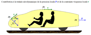
The equation of pressure drag state that, pressure drag which denoted as D is equal to the coefficient of drag which denoted as Cd multiplied the fluid density which denoted as r multiplied half of fluid velocity which denoted as V is square multiplied the area of reference which denoted as A.

Pressure drag can be calculate using this formula,

Pressure drag = Pressure drag coefficient x (Density x Velocity squred)/(2 x Reference area)

Mathematically can written,

D = Cd (ρ x v2) / (2 x A)

Where,

D = Pressure drag

Cd= Pressure drag coefficient

ρ = Density

 v = Velocity

 A = Reference area

Read more about Pressure vessel : It’s important facts and 10+ applications

How to reduce pressure drag?

The zone of the pressure low is appear behind the head, arms, back, and legs of the cyclists. It is very hard to reshape the parts from where the flow of the air is pass for reduce pressure drag.

The pressure drag can reduce in some ways, they are listed below,

  • Apply aero helmet
  • Body should be keep as low as possible
  • Hiding some equipment
  • The body should be keep in align
  • Head should be keep down
  • Double cap
  • Keep the kick tight
  • Point toes
  • Low profile goggles should be wearing
  • Hair should be shaving

How does air pressure affect drag?

The relationship with air pressure and drag is proportional to each other. Means the air pressure is increases then the drag amount is also increases and the air pressure is decreases then the drag amount is also decreases.

Pressure drag coefficient:

For any object which is moves in a motion due to force is applied that time drag is produce.

Pressure drag coefficient is the quantities resistance or drag of a particular matter in an environment which is based on liquid substance when force is exerted. The amount of the net force is act in the direction of the liquid substance flow due to shear stress and pressure on the plane of the particular matter.

Pressure drag coefficient
Image – Drag coefficient;
Image credit – Wikipedia

Read more about Compressive Stress and it’s overview with important facts

Pressures drag coefficient formula:

The formula of the coefficient of pressure drag is given below,

Fd = cd 1/2 ρ v2A

or, cd = 2Fd/ρ u2A}

Where,

Fd= Drag force express in Newton

cd = Drag coefficient

ρ= Density of a liquid substance express in kilogram per cubic meter

 v = Flow velocity of a liquid substance express in meter per second

A =Reference area for a particular body shape substance expressed in square meter The pressure drag coefficient depend upon some several facts of the parameters such as size and shape of any matter’s body, Flow of the liquid matter which is depend on Reynolds number, Mach number, Froude number and unevenness of the body.

How to calculate drag pressure coefficient?

Drag pressure coefficient can calculated using this formula,

gif

In eqn (2),

gif.latex?c p%20%3D%20%5Cfrac%7B2%7D%7B%5Crho%20v%5E2A%7D%5Cint %7BS%7D%5E%7B%7DdS%20%28p%20 %20p o%29%28%5Chat%7Bn%7D
gif

Where,

cd= Drag pressure coefficient

Fd = Drag force

A = Plan form area for a particular matter body

S = Wet surface for a particular matter body

cp = Pressure drag coefficient

cf = Friction drag coefficient

n̂= Perpendicular direction of a matter body which surface is dS. This is denoted the point from the fluid state to solid state

= Denoted the direction where shear stress is exerted on the matter of a body surface dS

î = Denoted the direction where vector is exerted in the flow of the stream

p = Pressure acted on the body of the matter at the dS surface

po = Far away pressure from the matter at the dS surface

Tw= Magnitude of the shear stress acted on the body of the matter at the dS surface

ρ = Density

v = Viscosity

Pressure drag vs. friction drag:

The compression between pressure drag and friction drag describe below,

ParameterFriction drag  Pressure drag
DefinitionWhen an object is flow in a liquid substance that time friction is appear between the liquid substance surface and the body of the matter and drag is produce. This type of drag is known as friction drag.Pressure drag is produce when the materials of a matter is resolved the force because of pressure is applied normally to the all points of the surface of a matter’s body.
Formulagif Where,
Cf = Skin friction coefficient
Tw = Skin shear stress which is applied in the surface plane of the body
v= Free stream speed for velocity of the body
ρ = Free stream speed for density of the body
1/2ρ v2 ≡ q = Free stream dynamic pressure for the body of the matter
gif or,
gif Where,
Fd = Drag force express in Newton
cd = Drag coefficient
ρ = Density of a liquid substance express in kilogram per cubic meter
v = Flow velocity of a liquid substance express in meter per second
A =Reference area for a particular body shape substance expressed in square meter  
DependentFriction between the surface and the body of the matterSize of the body
Pressure Drag and Friction Drag
Image – Pressure drag and Friction drag;
Image Credit – Wikimedia Commons

Pressure drag vs. skin friction drag:

The compression between pressure drag and skin friction drag describe below,

ParameterSkin friction drag  Pressure drag
DefinitionThe skin friction drag actually is an example of the state of aerodynamic drag. The skin friction drag can prevent force applied of a particular matter which is flowing in a motion in liquid substances.Pressure drag is mainly causes because of increasing pressure in front of a particular object and decreasing pressure in the back portion of the object.
Equationgif Where,
Cf= Skin friction coefficient
Tw= Shear stress for the local wall
q = Dynamic pressure for the free stream
gif
Now layers of boundary where pressure gradient is not applied in the direction of x that time momentum thickness can be express as,
gif
For the particularly turbulent flow the skin friction coefficient can be estimate using following equation,

For the particularly laminar flow the skin friction coefficient can be estimate using following equation,
gif
or,
gif
Where,
Fd = Drag force express in Newton
cd = Drag coefficient
ρ = Density of a liquid substance express in kilogram per cubic meter
v = Flow velocity of a liquid substance express in meter per second
A =Reference area for a particular body shape substance expressed in square meter  
DependentViscosityShape and size of the matter
RelationshipDirectly proportional to the viscosityDirectly proportional to shape and size of the matter
ExampleMotion of a airplane in air Motion of a matter in liquid substanceAir resistance Riding of a bicyclist Motion of a boat in water
800px Form drag and skin friction ratio.svg
Image – Skin friction drag;
Image Credit – Wikimedia commons

Read more about Shear modulus : Modulus of rigidity : It’s important facts and 10+ FAQ’s

Pressure drag vs. induced drag:

The compression between pressure drag and induced drag describe below,

ParameterPressure dragInduced drag
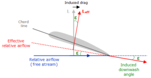
DefinitionWhen air molecules are compressed pressure drag produce.The position of the wing drag initiated by or working from the nature of the lift.
Relationship with speedThe relation between airspeed and pressure drag is directly proportional to each other.  The relation between airspeed and induced drag is indirectly proportional each other.  
Factor depend  1. Size and shape of the body of a object
2. Surrounding pressure
3.Motion of the liquid  
1. Size and shape of the body of a object
2. Inclination of a object
3. In the air flow condition of a object  
Induce drag downwash
Image – Induced drag;
Image Credit – Wikipedia

Pressure drag example:

Examples of the pressure drag is listed below,

  1. Airfoil
  2. Hummer H2 SUV
  3. Skydiver
  4. Bicycle
  5. Sphere
  6. Circular flat plate
  7. Honda civic
  8. Dodge ram pickup
  9. Toyota Camry
  10. Object moving in a liquid substance
  11. Speedboat

Read more about Drag Coefficient of Sphere.

11 Examples of Turbulent Flow: Detailed Explanations

Los Angeles attack sub 2 275x300 1

In our surroundings most of the flows of the viscous fluids are examples of turbulent flow. Examples of turbulent flow mainly flow via very small size ways and the flow will be slower than the regular.

12+ Examples of Turbulent Flow is listed below,

What is the meaning of turbulent flow?

Turbulent flow mainly occurs when excessive amount of kinetic energy is present in the flow of motion in the fluids. By the help of Reynolds number the flow of turbulent can be easily determined in the fluid.

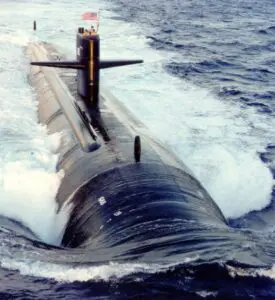
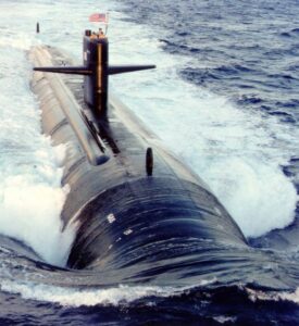
Turbulent flow can be explain as, the fluid or in turbulent water  an unbalanced situation is appear in restlessness or compound of two or than two liquid substance. For the reason of the restlessness of the fluid the velocity, pressure and other physical parameters are not same at the each point of the fluid.

Los Angeles attack sub 2
Image – Turbulent flow;
Image Credit – Wikipedia

If the value of the Reynolds number is more than 3500 then the type of fluid known as turbulent flow.

In which factors the flow of the turbulent is dependent?

The factors the flow of the turbulent is dependent is listed below,

The factors are briefly discuss,

Velocity:

The flow of turbulent is depends on the physical property of velocity. The relationship with the flow of turbulent and velocity is proportional to each other. Means if the rate of velocity is increases then the value of flow of turbulent is also increases and if the rate of velocity is decreases then the value of flow of turbulent is also decreases.

Viscosity:

The flow of turbulent is depends on viscosity. The relationship with the flow of turbulent and viscosity is indirectly proportional to each other. Means if the rate of viscosity is increases then the value of flow of turbulent is decreases and if the rate of viscosity is decreases then the value of flow of turbulent is increases.

Pressure:

Another parameter where the flow of turbulent is depends that is pressure. The relationship with the flow of turbulent and pressure is directly proportional to each other. Means if the rate of pressure is increases then the value of flow of turbulent is also increases and if the rate of pressure is decreases then the value of flow of turbulent is also decrease in the same way.

12+ Examples of Turbulent Flow facts are broadly discuss in below,

Flow of the lava:

In the flow of the lava turbulent flow is appearing. If we observe the flowing condition of the lava then we easily can observe that when lava is came out from the inside of the earth to the surface of the earth that time the particles are not flow in a directional motion the layers of the lava is mixing with each other for this particular reason the physical parameters like velocity, pressure, viscosity is not remain same at each of the molecules of the fluid.                

examples of turbulent flow
Image – Flow of lava;
Image Credit – Wikimedia Commons

Flow of the blood in arteries:

In the flow of the blood in arteries the flow of turbulent is present. If we observe the flowing condition of the blood then we easily can observe that when blood is flow through the arteries the particles are not flow in a directional motion. The layers of the blood is mixing with each other for this particular reason the physical parameters like velocity, pressure, viscosity is not remain same at each of the molecules of the fluid and turbulent flow appear.

800px Coronary Artery Disease
Image – Flow of the blood in arteries; Image Credit – Wikimedia Commons

Transpiration of oil through the pipelines:

In the transpiration of oil through the pipelines flow of turbulent is present. If we observe the flowing condition of fluid then we easily can observe that when fluid is flow through the pipes the particles are not flow in a directional motion.

Flow in the wake of the boat:

In the flow in the wake of the boat the flow of turbulent is present. The flowing condition of fluid is directional motion and the physical parameters like velocity, pressure, viscosity is not remain same at each of the molecules of the fluid and turbulent flow appear.

Aircraft wing tips:

In aircraft wing tips the flow of turbulent is present. The physical parameters like velocity, pressure, viscosity is not remain same at each of the molecules of the fluid and turbulent flow appear.

Currents in the atmosphere:

In the currents of the atmospheric the presence of the turbulent flow can be observe.

Currents in the ocean:

In the currents of the oceans the flow of turbulent is present. The physical parameters like velocity, pressure, viscosity is not remain same at each of the molecules of the fluid and turbulent flow appear.

Smoke:

In the smoke of turbulent is present. When smoke is mix with the surrounding the physical parameters like velocity, pressure, viscosity is not remain same at each of the molecules of the fluid and turbulent flow appear.

800px Ognisko ubt 0126
Image – Smoke;
Image Credit – Wikimedia Commons

Car exhaust:

In the flow of the car exhaust flow of turbulent is present. When smoke is emitted from the vehicle smoke is mix with the surrounding the physical parameters like velocity, pressure, viscosity is not remain same at each of the molecules of the fluid and turbulent flow appear.

Rivers:

In river water the layers are mix with each other and turbulent flow is present.

Herault River Agde 09
Image – River;
Image Credit – Wikimedia Commons

Read more about Mass Flow Rate : Its Important relations and FAQs

Air flow through the air conditioning system:

In air flow of ac turbulent is present because the layers are not flow in one direction.

Windmill:

In windmill flow of turbulent is present. When windmill start the surrounding air mix up a turbulence is appear.

Read more about Wind Turbine Efficiency : Complete Insights and FAQs

Examples of turbulent flow
Image – Windmill;
Image Credit – Wikimedia Commons

Frequent Asked Question:-

Question: – Describe the relation between Reynolds number and flow of the fluid.

Solution: – Reynolds number is dimensionless physical factor. By the using Reynolds number easily can estimate the type of the flow of viscous fluid. The Reynolds number easily can understand us the flow is laminar or turbulent.

The relation between Reynolds number and flow of the fluid is given below,

gif
gif

Where,

Re = Reynolds number

ρ = Density for the viscous fluid

V = Characteristic velocity for the viscous fluid

L = Characteristic length for the viscous fluid

μ = Dynamic viscosity for the viscous fluid

v = Kinematic viscosity for the viscous fluid

The change of state middle of the dynamic viscosity and kinematic viscosity is given below,

v = μ/ρ

Reynolds number:-

Reynolds number can be deriving as the ratio between the inertia force and viscous force.

Mathematically Reynolds number can be written as,

Re =ρuL/μ

Where,

Re = Reynolds number

ρ = Density of the viscous fluid

u = Speed of flow of the viscous fluid

L = Characteristics linear dimension of the viscous fluid

μ = Dynamic viscosity of the viscous fluid

With the help of Reynolds number we can estimate several properties of the fluid such as viscosity, velocity, length, pressure and many others.

Read more about Reynolds number : It’s 10+ Important facts

Question: – Write the major difference between flow of laminar and flow of turbulent.

Solution: – The major difference between flow of laminar and flow of turbulent is discuss below,

ParametersLaminar flowTurbulent flow
Reynolds numberLess than 2000Greater than 4000
ViscosityLowHigh
Movement of the molecules in the liquid substanceRegular movement is presentIrregular movement is present
Mathematical analysisEasy to doComplication is appear
Motion DirectionLayers of the flow of the water is flow in one direction and no mixing of the liquid is occurAverage motion is present and that is not one directional and mixing of the liquid is occur
OccurSmall size diameter rodBigger size diameter rod
Shear stressShear stress of the flow of laminar is depending on the viscosity of the liquid substance and not depends on the liquid substance density.Shear stress of the flow of turbulent is depending on the density of the liquid substance.

11 Examples of Laminar Flow: Detailed Explanations

5b9bc62bf8fd409b53f9939d3688d0c798bb28d9 300x200 1

Examples of laminar flow mainly found in the cases where the flow of the channel is comparatively smaller than the regular flow. In this article examples of laminar flow and its related everything is prate.

The 11+ examples of laminar flow are listed below:-

What is the meaning of laminar flow?

In the laminar flow the physical quantities remains same for this particular reason the laminar flow also called as the flow of streamline. In the laminar flow pressure, velocity and many more physical quantities remains same.

Laminar flow explain as,  the viscous fluid when flow in a motion that time the molecules of the viscous fluid can move in parallel layers at a certain time period. In the flow of the laminar velocity and pressure and other parameter of physical stays same at the each of the particles of the parallel layers.

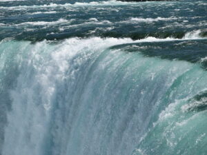
800px Closeup of Horseshoe Falls
Image – Laminar flow;
Image Credit – Wikipedia

When a viscous fluid flow is a motion through a closed system such as rod or pipe and middle of the flat plates that time flow of the laminar is appear. Laminar flow of a viscous fluid depends upon viscosity, velocity and the shape or size of the rod.

In which factors the flow of the laminar is dependent?

If we go through the law of Poiseuille then how the flow of the laminar is dependent on the physical factor easily can be understand.

The flow of laminar depends on some factors. The factors are,

Viscosity:

The flow of laminar depends on viscosity. The relationship with the flow of laminar and viscosity is indirectly proportional to each other. Means if the rate of viscosity is increases then the value of flow of laminar is decreases and if the rate of viscosity is decreases then the value of flow of laminar is increases.

Velocity:

The flow of laminar depends on velocity. The relationship with the flow of laminar and velocity is directly proportional. Means if the rate of velocity is increases then the value of flow of laminar is also increases and if the rate of velocity is decreases then the value of flow of laminar is also decreases.

Pressure:

The flow of laminar depends on pressure. The relationship with the flow of laminar and pressure is directly proportional to each other. Means if the rate of pressure is increases then the value of flow of laminar is also increases and if the rate of pressure is decreases then the value of flow of laminar is also decrease in the same way.

Size of the rod or pipe:

The flow of laminar depends on size of the rod or pipe. The relationship with the flow of laminar and size of the rod or pipe is indirectly proportional to each other. Means if the rate of size of the rod or pipe is increases then the value of flow of laminar is decreases and if the rate of size of the rod or pipe is decreases then the value of flow of laminar is increases.

The relation between Reynolds number and flow of the fluid:

Reynolds number is dimensionless physical factor. By the using Reynolds number easily can estimate the type of the flow of viscous fluid. The Reynolds number easily can understand us the flow is laminar or turbulent.

The relation between Reynolds number and flow of the fluid is given below,

gif
gif

Where,

Re = Reynolds number

ρ = Density for the viscous fluid

V = Characteristic velocity for the viscous fluid

L = Characteristic length for the viscous fluid

μ = Dynamic viscosity for the viscous fluid

v = Kinematic viscosity for the viscous fluid

The change of state middle of the dynamic viscosity and kinematic viscosity is given below,

v = μ/ρ

Reynolds number:-

Reynolds number can be deriving as the ratio between the inertia force and viscous force.

Mathematically Reynolds number can be written as,

Re = ρuL/μ

Where,

Re = Reynolds number

ρ = Density of the viscous fluid

u = Speed of flow of the viscous fluid

L = Characteristics linear dimension of the viscous fluid

μ = Dynamic viscosity of the viscous fluid

With the help of Reynolds number we can estimate several properties of the fluid such as viscosity, velocity, length, pressure and many others.

The 11+ examples of laminar flow derive briefly in below;

Aircrafts:

An aircraft is a machine or vehicle that can fly with the support of air. An aircraft can fly using the force of static lift, force of dynamic lift with the air foil. An aircraft is an example of laminar flow which we use in our practical daily life. By the help of aircraft anybody can reach to their desired place in a very short time.

Examples of laminar flow
Image – Aircraft;
Image Credit – Unsplash

Canals:

A canal is an example of laminar flow which we use in our practical daily life. Canal actually a waterway which made of artificially for transfer vehicles in the waterway or to build the management of the drainage system. Canal can carry free, in a smooth calm surface where water easily can flow under the pressure of atmospheric.

examples of laminar flow
Image – Canal;
Image Credit – Wikimedia Commons

River:

A river is an example of laminar flow which we use in our practical daily life. A river is actually a natural waterway that depth can be huge or shallow. In the river the water is falls towards the downstream due to the gravitational force. A smaller size river that also known as brook, stream or creek.

Wilkin River close to its confluence with Makarora River Otago New Zealand
Image – River;
Image Credit – Wikimedia Commons

Taps:

A tap is an example of laminar flow which we use in our practical daily life. When the water is comes through the tap the flow will straight there turbulence is not present. When the water is comes from taps that moment pressure and viscosity became same at each point of the water.

Read more about Pipe Elbow Dimensions : Exhaustive Problems Solution and Facts

Tea pouring from kettle:

Tea pouring from kettle is an example of laminar flow which we are used in our practical daily life. When tea is comes through the nozzle of the kettle the flow will straight and there turbulence is not present for this reason laminar flow is appearing. When the tea is comes from kettle that moment pressure and viscosity and other parameter of physical remain same at each point of the tea.

5b9bc62bf8fd409b53f9939d3688d0c798bb28d9
Image – Tea pouring from kettle; Image Credit – Snappygoat

Viscous fluid:

Every viscous fluid is an example of laminar flow which we use in our practical daily life. In every viscous fluid pressure, viscosity and other parameter of physical remain same at each point of the fluid for this reason laminar flow is appearing.

Read more about Volumetric flow rate : It’s All important Concept

Fountains:

A fountain is an example of laminar flow which we use in our practical daily life. A fountain is actually a reservoir which is used as decoration. In the decorative reservoir mainly water is discharge. In every fountain the pressure, viscosity and other parameter of physical remain same at each point of the water for this reason laminar flow is appearing.

Schlossplatzspringbrunnen Schlossplatz Stuttgart 2015 03
Image – Fountain;
Image Credit – Wikimedia Commons

Read more about Mass flow rate : Its Important relations and FAQs

Smoke:

A smoke is an example of laminar flow which we produce in our practical daily life. When smoke is comes there turbulence is not present for this reason laminar flow is appearing. In smoke pressure and viscosity and other parameter of physical remain same at each point.

Candle smoke structure 1
Image – Candle smoke;
Image Credit – Wikipedia Commons

Water balloon:

A water balloon is an example of laminar flow which we use in our practical daily life. When water is comes through the balloon the flow of the fluid will straight and there turbulence is not present for this reason laminar flow is appearing.

500px Balloon burst
Image – Water balloon;
Image Credit – Wikimedia Commons

Blood flow:

Blood flow an example of laminar flow which we use in our practical daily life. When blood is flow that time layer will be one directional.

Blood Anemia
Image – Blood flow;
Image Credit – Wikipedia Commons

Honey run from the container:

Honey run from the container an example of laminar flow and that time turbulence is absent and viscosity ans velocity stays same in each and every point of the honey.

11 Ionization Energy Example: Detailed Explanations

Compact fluorescent straight crop 300x145 1

In this article “Ionization energy examples” with their detailed explanations are derived. The meaning of higher ionization energy means facing the difficulty to subtract any electron from the chemical bonds.

11 + ionization energy examples are listed below,

Fluorescent lamp:

Fluorescent lamp is a very light weight vapor lamp which inside mercury is present. In the fluorescent lamp fluoresce is placed for this reason visible light is delivered.  Fluorescent lamp works in electric current. When electric current is deliver to the fluorescent lamp that time gas is energized the vapor of mercury from this ultraviolet radiation is emitted and the radiation of ultraviolet objective the coating of the phosphor in the liner wall of the lamp.

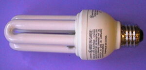
Ionization energy example
Image – Fluorescent lamp;
Image Credit – Wikipedia

Fluorescent lamp main parts:

Electrodes:-

Inside the fluorescent lights two set electrodes are situated. The electrodes in fluorescent lights are attached with the fixture through two small size metal prongs. These prongs are clearly visible to the outside of the fluorescent lights. In the CFLs electrodes are not visible from the outer side because its base is screw type.
Starter:-

Only in the older type fluorescent lights have the component name starter. These starters are small metal cylinder. The starters of the fluorescent lights cause the delay of the electricity to the gas tube.

800px Disassembled USSR starter
Image – Starter;
Image Credit – Wikipedia Commons

Tube:-

In the tube of the fluorescent light gas is placed. The usual fluorescent lights are tube shaped into the straight cylinder. In the CFLs, compact fluorescent light have a tube which is bending and look like U letter. In neon lights tubes are looks like words or graphics.

Gas:-

In the fluorescent light tube some gases are inset such as argon, xenon, neon and also vapor of mercury is placed. Gas of the fluorescent light is help to discharging the light. When a particular amount of voltage is applied the atoms of the ionized gas is charged and excited. At this moment proton of the ionized gas atoms also excited.
Phosphor coating:-

With the help of a metal named phosphor the inside tube of fluorescent light is coated. The coatings of the phosphor affect the colour emitting of the fluorescent light.
Ballast:-

In the fluorescent light the ballast can be two types one is electronic and another one is magnetic. In the new type of fluorescent light only the electronic ballast is present it is not too loud or hot like magnetic ballast.

Advantages of fluorescent lamp:-

  • Low heat radiation
  • Lower power consumption
  • Longer life
  • Not required warning up period
  • Good quality of light
  • Higher efficiency

Disadvantages of fluorescent lamp:-

  • Initial cost is high
  • Fluctuation of voltage is affected
  • Produce radio interface
  • Sometime light output is fluctuating

Electrical bulbs:

Electrical bulb is actually a simplest version of an electrical lamp. The electrical bulb is actually a very small size and simple light source which helps to brighten the dark place. The other name of the electrical bulb is incandescent bulb.

Application of Electrical bulb:-

  • In portable lighting the electrical bulb is widely used such as table lamps
  • In vehicle headlights and lights the electrical bulb is used
  • Commercial lighting
  • Household lighting
  • Advertising and decoration the electrical bulb is used.

Advantages of Electrical blub:-

  • No harassment in installation
  • Longer life period
  • Economical
  • Affordable
  • Easily available in verities shapes and sizes
  • Working period is also high
  • High output

Disadvantages of Electrical blub:-

  • Energy insufficient
  • Produce warm light
  • Need to handle very carefully because it is made of glass thus can brake easily
  • Breakable parts are very sharp can cut in the skin
  • Inside the electrical bulb mercury, argon is present for this reason the electrical bulb should be handle carefully.

Solvation:

Materials which are made of plastic they are attacked by chemical reaction and salvation. The process method of salvation only happened with polar solvents. The concept of salvation is distinct from solubility and dissolution.

ionization energy example
Image – Solvation;
Image Credit – Wikipedia

Solvation can be explain as, the method in which chemical association is present between the solvent and molecules of solute.

The factors which are affecting solubility,

  • Pressure
  • Temperature
  • Surface area
  • ph
  • Nature of Solvent/Solute

Read more about Pressure vessel : It’s important facts and 10+ applications

Calcium nitride:

The formula of the calcium nitride is Ca3N2. The molar mass of the calcium nitride is 148.25 gram per mol. The calcium nitride can present in a lots of state.

Free radicals:

A definition of free radical is any molecular house is capable to contain electron in unpaired state independently. Radicals can be present in two state one is unstable and another is highly reactive.

The radical can give an electron to other molecules or can take electron from other molecules. When the radical can give an electron to other molecules that time it behave like oxidants and when the radical can take an electron from other molecules that time it behave like reluctant.

Free radical polymerization of tetrafluoroethylene
Image – Free radicals;
Image Credit – Wikimedia Commons

Some sources name of the free radicals is listed below,

  • Exercise
  • Smoking
  • Mitochondria
  • Inflammation
  • Phagocytosis
  • Ozone
  • Radiation
  • Pesticides
  • Pollutions of the environments
  • Industrial solvents
  • Xanthine oxidase

Condensation reactions:

The condensation reactions are a part of chemical reactions. In condensation reactions smaller size molecules join together and make a larger size molecule. In the condensation reactions monomers means the smaller size molecules made a bond and name colavent bond and this bond is allow the joining the molecules and to make larger molecules.

The examples of condensation reactions are Glucose, Galactose.

The formula of condensation reactions is,

AH + BOH ­-> AB +H2O

Where,

A = The molecules in condensation reactions is condensed

B = The molecules in condensation reactions is condensed

AB = Compound product in condensation reactions

Sodium chloride:

The regular salt chemical name is sodium chloride. Sodium chloride is an electrolyte and helps to regulate the total quantity of water in our human body. But this chemical element also causes lot of problem in human body. They are listed below,

  • Diseases of liver
  • Diseases of kidney
  • Congestive heart failure
  • High blood pressure
  • Fluid retention

Sodium Chloride preparation process:

When chloride and sodium mixed together then it is response to generate sodium chloride.

The formula in below,

2 Na (s) + Cl2 -> 2NaCl (s)

Hydrogen:

The hydrogen is a family member of chemical elements. It is a tasteless, colourless, odourless, flammable gaseous matter. The atom of the hydrogen contain a nucleus which surrounding have proton bearing which have the charge of positive electrical charge and an electron bearing is present which have the charge of negative electrical charge. In the whole universe hydrogen is one of the most abundant matters.

Three isotopes are present in the hydrogen. The isotope mass 1 is called protium and it symbol is H, and written as H1,  The isotope mass 2 is called deuterium and a nucleus is present which contain one proton one neutron and it symbol is d, and written as H2, The isotope mass 3 is called tritium and it symbol is t, and written as H3 and its nucleus has one proton two neutrons.

EMclrZrXkAAbthj
Image – Isotopes of hydrogen;
Image Credit – Wikimedia Commons

Nitrogen:

In the periodic table of group 15 nitrogen is belonging. Nitrogen is lightest and non-metal of periodic table. In earth nitrogen is very important element. In the components of the nitrogen all proteins are placed. Nitrogen found in the system of living.

The atomic number of nitrogen is 7, atomic symbol is N. Most commons isotopes of nitrogen are Nitrogen – 14.

Applications of nitrogen:-

  • Food packaging
  • Manufacturing
  • Aircraft fuel system
  • Industry of light bulbs
  • Fire suppression system
  • Industry of chemical
  • Tire filling system
  • Manufacturing of electronics
  • Manufacturing of stainless steel
  • Fertilizer
1280px thumbnail
Image – Aircraft Fuel System;
Image Credit – Wikimedia Commons

Oxygen:

Pure form of oxygen is not flammable. It is a tasteless, colourless, odourless gaseous matter. In our surrounding some objects are present which are not burning in the air but can burn with the help of oxygen. Oxygen is very essential for our human life. The atomic number of oxygen is 8, atomic symbol is O.

It is reactive element and when it is added with another element oxide form. Oxygen could not make some oxide with some elements such as neon, argon, helium, and krypton.

Applications of oxygen:-

  • Mining
  • Rocket propulsion
  • Production in glass industry
  • Production in stone industry
  • Medical field
  • Biological field
  • For melting and cutting of the metals

Aluminium:

In the table of the periodic aluminium is 13th element means the atomic number of the aluminium is 13. Aluminium is higher reactive and it is always ready to combine with other elements, for this reason in environment aluminium not present itself it presence can be observe with other elements.

Aluminium has high electrical conductivity for this reason it is used in the cables of the electric. Aluminium is silver metal which have extremely high corrosion resistant compare to others metals.

Application of aluminium:-

  • Personal vehicle
  • Construction of ships
  • As a components in aircraft
  • Window frames
  • Power lines
  • Household
  • Industrial applications
  • Construction of trains
  • High rising building
800px Cessna172 CatalinaTakeOff
Image – Aircraft;
Image Credit – Wikipedia

Frequent Asked Questions:-

Question: Ionization energy examples based on which equation?

Solution: The basic ionization energy equation is,

X(g) -> X (g) + e

More ionization energy equations,

1st equation of the ionization energy is,

X(g)  -> X +  (g) + e^-

2nd equation of the ionization energy is,

X(g)  -> X2 + (g) + e^-

3rd equation of the ionization energy is,

X2(g)  -> X3 + (g) + e^-

Internal Energy of an Ideal gas: Several Facts and Detailed Explanations:

The “Internal energy of an ideal gas” is not depending upon the path of a system which is closed but the internal energy of an ideal gas depends on the initial state and final state of the system.

From the law of thermodynamics we get a crystal clear concept about the internal energy of an ideal gas. The internal energy of an ideal gas can be explain as, the total amount of energy is amalgamated with the motion that could be vibration motion, rotation motion or translation motion of the molecules or atoms of a matter in the system.

Read more about Carnot Cycle: Its Important Features along with 16 FAQ’s

What is internal energy of an ideal gas?

For an ideal gas the amount of internal energy for a system only depend upon temperature. But for the real gas the amount of internal energy for a system depend upon temperature, volume, pressure.

The internal energy of an ideal gas is a property of extensive and the amount of energy of a gaseous matter cannot determine directly. The internal energy of an ideal gas is in a system the molecules of a gaseous matter, the amount of internal energy transferring in the form of thermodynamic work and heat.

Internal energy of an ideal gas
Image – The carnot heat engine of internal energy of an ideal gas;
Image Credit – Wikipedia
Thermally Agitated Molecule
Image – Temperature;
Image Credit – Wikipedia

For an ideal gas the total amount of internal energy is directly proportional to the temperature and also the total number of the molecules of mole of a substance which is present in the gaseous state.

Read more about Thermal diffusivity : It’s all Important Facts and FAQs

So mathematically the internal energy of an ideal gas can be express as,

dU = nCvdT…… eqn (1)

Or, U = CvnT…………. eqn (2)

From the equation (1) term nCvT  is used from the kinetic energy of an ideal gas.

Where,

U = The amount of internal energy of a gas

Cv = At constant volume the amount of heat capacity of a gaseous substance

n = The total number of moles of a gaseous substance

T = Temperature of the system

Internal energy of an ideal gas formula:

In the thermodynamics the change of total amount of internal energy which is expressed as ΔU can determine but for an ideal gas the amount of absolute internal energy can estimate.

Internal energy of an ideal gas formula is,

gif

Where,

U = Internal energy of an ideal gas

cv = Heat capacity of the specific isochoric

m = Mass of an ideal gas

T = Temperature

To calculate the amount Internal energy of an ideal gas at first we need imagine a gas substance is blockaded to a cylinder that time the volume of the ideal gas should be in constant state and the ideal gas should to cool down and reaches at absolute zero temperature.

In this particular state all particles of the ideal gas at rest position and there is no internal energy is present. The total amount of heat is expressed as Q is transferred at the constant state of volume until the ideal gas temperature is reaches to T. Now in this state the total amount of heat which is necessary for the internal energy is reaches at U.

Internal energy of an ideal gas derivation:

In a system of thermodynamic the amount of internal energy can be converted into potential energy or kinetic energy. For the system of the thermodynamics three types of energy such as internal energy, potential energy and kinetic energy can contained.

Derivation internal energy for an ideal gas:-

For an ideal gas substance the internal energy depend upon the kinetic energy and potential energy.

gif
gif
gif
gif

We know that,

M/m = Na

Kavg = 1/2 3RT/Na

Kavg = 3/2 kT because  k = R/Na

How does the internal energy of an ideal gas differ from that of real gas?

The ideal gas explain as, the gaseous substance which are obeys the law of gases at any condition of temperature and pressure. The real gas explain as, the gaseous substance which are not obeys the law of gases.

The difference between the internal energy of an ideal gas and real gas is discuss below,

Parameters Ideal gas Real gas
Pressure High Low
Intermolecular attraction force Not present Present
Volume No definite volume Definite volume
Existence in environment Not present and the ideal gas is hypothetical gas Present
Elastic collision of molecules Yes No
Interaction with others gas No Yes
Law of gases Obey Does not obey
Velocity   Not present   Present  
Mass Not present   Present  
Volume Not present   Present  

Specific internal energy of an ideal gas:

The specific internal energy of an ideal gas which is expressed as u explain as, the amount of internal energy of an ideal gas matter in per unit mass of the particular ideal gas matter.

Read more about Specific Enthalpy : Its important properties & amp; 8 FAQ’s

The formula of the specific internal energy of an ideal gas is,

u = U/m

Where,

u = Specific internal energy of an ideal gas in joule per kilogram

U = Internal energy of an ideal gas in joule

m = Mass of an ideal gas in kilogram

The S.I. unit of the specific internal energy of an ideal gas is joule per kilogram. The dimension of specific internal energy of an ideal gas is L2T-2.

Change in internal energy of an ideal gas:

From the laws of kinetic energy it’s clearly shown that kinetic energy of a particle has a directly relation with temperature from that change in internal energy of an ideal gas directly connected.

Change in internal energy of an ideal gas only depends on the temperature it is not depend on the other physical parameters like volume, pressure. If initial temperature, final temperature is known for the system then change in internal energy of an ideal gas easy to determined.

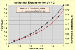
Whether the system can follow any process like isentropic, isobaric or isochoric or any other method the change in internal energy of an ideal gas is irrelevant. In one word we can say change in internal energy of an ideal gas only ruled by the state of the gaseous matter not ruled by the process of the gaseous matter. If the temperature is differ in the system only for that case internal energy can be differ for an ideal gaseous substance. The change in internal energy of an ideal gas can be zero in the process of isothermal.

Isothermal expansion of an ideal gas
Image – Isothermal Process;
Image Credit – Wikimedia Commons

Read more about Isothermal process : It’s all important facts with 13 FAQs

By the process of the thermodynamic the clear relation between change in internal energy of an ideal gas and temperature easily can investigate of gaseous matter.  In the process of isochoric on the gas no workdone is happened. In the process of isochoric on the gas heat is input for this reason change in internal energy of an ideal gas is increases.

What is the change of internal energy?

In a system of thermodynamic the change in internal energy is derive in this way the sum of the internal energy changes for the gaseous matter is equal to  the net workdone of a thermodynamic system and the total amount of heat is deposal to the system and the surrounding of the system.

800px Temperature and internal energy.svg
Image – Internal energy and Temperature;
Image Credit – Wikimedia Commons

The formula for the change in internal energy of an ideal gas is,

Δ U = Q + W

Where,

ΔU = The total amount of change in internal energy of an ideal gas in a system

 Q = The amount of heat transfer between the system and the system’s surroundings

 W = Work done by a system

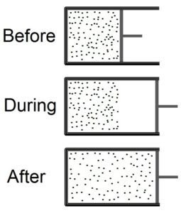
In some process there is no change in internal energy. The processes are cyclic process, isothermal and free expansion. In these processes the amount of internal energy is same because the temperature of the system remains unchanged.

Before during after sudden expansion
Image – Free expansion in gas;
Image Credit – Wikipedia

How to calculate change in internal energy of an ideal gas?

From the 1st law of the thermodynamic we can a concept about change in internal energy of an ideal gas.The amount of internal energy of an ideal gas is equal to the heat flow and PV workdone by the system.

The quantity of the internal energy that could be change for a gaseous matter that always should be equal to the workdone of the system and the amount of input heat and amount of output heat.

Formula for calculate change in internal energy of an ideal gas:-

Q =ΔU = W…….eqn (1)

Q = ΔU + PV

Because we know that, the amount of heat is added or removed is always equal to the total sum of the internal energy which is changed and the workdone of PV.

From the eqn (1) after arranging we get,

ΔU = Q – PV……. eqn (2)

Frequent Asked Questions:-

Question: – Is all-time the values of the internal energy of a substance remain positive or it can be negative?

Solution: – No, all-time the values of the internal energy of a substance cannot remain positive.

Some time the value of the internal energy can be negative. We can calculate the value of internal energy from the sum of workdone and heat. Negative value of internal energy of an ideal gas means the value of final energy is low than the value of initial energy.

Question: – Give some examples of internal energy.

Solution: – Some examples of internal energy listed below,

  1. Vapor of a liquid substance
  2. Shaking of a liquid substance
  3. Batteries
  4. Compressed gasses
  5. Increasing the temperature of a substance

15 Radioactive Decay Examples: Detailed Explanations

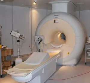
800px MRI Philips 300x274 1

In this article Radioactive decay examples are derived. Radioactive process is actually a continuous breakdown process of a matter’s atomic nucleus. In this process energy is emitted from any matter’s nucleus.

16+ radioactive decay examples are given in section of below,

  • Medical equipment
  • Glass
  • Ceramics
  • Clocks and watches
  • Smoke detector
  • Fertilizers
  • Gas Lantern Mantles
  • Food
  • Glowing items
  • Recycled metal
  • Irradiated Gemstones
  • X ray imaging
  • Security
  • Measurement
  • Space exploration
  • Human body

Medical equipment:

In various machines in the medical field radioactive element is widely used. From where radioactive decay is emitted these types of material are used in the medical field for treating health of a patient. Nuclear Regulatory Commission department regulate the use of radioactive decay in medical field.

Near about one third patients are admitted for acted a rare and fatal liver disease using radioactive or radiation materials.  The radioactive or radiation materials are called radio pharmaceuticals. To reduce the tissue of the cancerous, reduce and shrink a tumor this radioactive object is used.

800px MRI Philips
Image – Medical equipment;
Image Credit – Wikipedia Commons

Glass:

In the industry of glassware the radioactive decay is used. Thorium – 232 and potassium – 40 radioactive type objects is used inside the glassware factory. Some glass made product also contain uranium this type of glass is called Vaseline glass.

Glass is transparent amorphous solid and it is non crystalline. In the glass others chemical are also present like silica.

Radioactive decay examples
Image – Glass;
Image Credit – Wikimedia Commons

Ceramics:

Thorium, uranium, potassium radioactive type objects is used inside the ceramics. Ceramics can be divided in two categories as non metallic material and inorganic material. In the field of production engineering the examiner are tried to new type products of ceramics that general people can use in their everyday lifestyle.

In almost everywhere ceramics are present. In bricks, glass, plates even in toilet the ceramic made of products are present.  In automobile, clock and watches, snow skies, airplanes, appliances, space shuttles the ceramics products are available. Even in some superconductors ceramics presence can be observe.

In the ceramics the objects which are present they are powders, water, earthen elements, mixture of clay and mixing all together the desired object is made.

800px Boeotian Geometric pottery AM of Thebes 201170
Image – Ceramics;
Image Credit – Wikimedia Commons

Clocks and watches:

In our daily the most common and useful radioactive example is clocks and watches. Promethium – 147 radioactive type objects is used inside the clocks and watches. Another type radioactive type objects is used inside the clocks and watches is Hydrogen – 3.

For this reason luminous type dials actually a compromising. For this reason in dark area we easily can see the time without any hassle. Now a day where this modern type watches is used. In older watches and clocks Radium – 226 is used.

Radium Dial
Image – Clock and watches;
Image Credit – Wikipedia

Smoke detector:

The term for the smoke detector is smoke alarm. The radioactive example which is use in our regular life this is the smoke detector. Mainly alpha decay is used in the smoke alarm. Americium – 241 this radioactive object is used inside the smoke detector.

The Americium – 241 radioactive elements is actually particularly placed in the middle portion of the charged plates. From Americium – 241 element release alpha decay to the environments.

Two plates which are charged are used to construct the design of smoke detector. Others things which are used in the design of the smoke detector they are, a battery, a mechanism of alarming, a detector battery. The terminals are attached to the equipment of the smoke detector in a very interesting way. One terminal of the smoke detector is attached with the detector of current and another one terminal is attached with the positive side plate of the smoke detector.

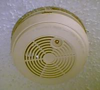
Ceiling smoke alarm
Image – Smoke detector;
Image Credit – Wikimedia Commons

Others some facts which are we to concern about is listed below,

  • At least in every 9 – 10 years the smoke detector should be definitely replaced.
  • The connection of the smoke detector always interconnected.
  • Large buildings should contain more smoke detector.
  • Monthly checking and maintenance is needed.

Fertilizers:

Fertilizer is an element which is mainly used in agriculture field for improve the productivity and growth of the plants. Fertilizer actually a element which is enhance the fertility naturally of the soil or elements which carry the chemicals alternatively use as soil by prior crops.

In the fertilizer the radioactive elements are used they are uranium and thorium. The other chemical element which are contain by the fertilizer is hydrogen, nitrogen, oxygen, phosphorus, calcium, sulfur, sodium, silicon, aluminium and many more.

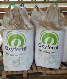
Oxyfertil fertilizer
Image – Fertilizer;
Image Credit – Wikimedia Commons

Gas Lantern Mantles:

Thorium – 232 radioactive elements is used in the gas lantern mantles. This gas lantern mantles actually incandescent lights. When fuel is burn like kerosene, propane and white gas heat is produce and as a result mantles is made from which light is comes.

The gas lantern mantles components made of ceramics other elements present in this is cerium oxide, thorium oxide and magnesium oxide. The construction of the gas lantern mantles is very simple.

800px Glowing gas mantle
Image – Gas lantern mantles;
Image Credit – Wikipedia

Food:

There is lots of food is present in nature from their radioactive decay is always emitted.  The food items are,

Brazil nut – From the Brazil nut near about 12000 picocurie per kilogram radiation decay is emitted.

Butter beans – From the butter beans near about 4600 picocurie per kilogram radiation decay is emitted.

Bananas – From the bananas near about 3500 picocurie per kilogram radiation decay is emitted.

Avocados – From the Avocado near about 2500 picocurie per kilogram radiation decay is emitted.

Water – From the water near about 100 picocurie per kilogram radiation decay is emitted.

Red meat – From the red meat near about 3000 picocurie per kilogram radiation decay is emitted.

Peanut butter – From the peanut butter near about 120 picocurie per kilogram radiation decay is emitted.

Glowing items:

In lots of glowing item which we are used in our daily life radioactive element is present. Mainly in the glowing item thorium and uranium are used. These items can glow in dark places without battery or electricity.

In the glowing items mainly very low level radiation of beta is emitted. The emission of the beta radiation easily can be stopped with help of cloth or sheet of paper.

Recycled metal:

We are known the process of the recycle is very convenient for us and also for our surrounding. But some time the process of recycle can causes some unwanted bad situation. The metals which are used again and again for recycling causes emitting of radiation decay. We always should some take some care of it,

  1. Taking a distance
  2. Time limitation
  3. Checking shielding

Irradiated Gemstones:

In lots of gemstones which we are used in our daily life radioactive element is present. Mainly in the irradiated gemstone item gamma radiation is continuously emitted. The irradiation is a term which meaning is very board. In irradiated gemstones full range of radiation of electromagnetic present and also visible light, X rays, ultraviolet rays, infrared radiation is present.

X ray imaging:

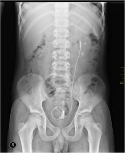
X ray imaging is a very process which is done without any pain and it is very speedy process. From this x ray imaging the radiation is emitted. Mainly by the help of x ray a picture is taken for any particular place of our body.

800px Medical X Ray imaging QGT06 nevit
Image – X ray image;
Image Credit – Wikipedia Commons

Beam of the ray is going through of our body and after that absorbed different amount of radiation which is depend upon the material density.

But excess amount of doing x ray imaging is not good for our body.

Mainly the images are taking by the help of x ray process is,

  • Arthritis
  • Bone cancer
  • Osteoporosis
  • Dental decay
  • Fracture
  • Blocked blood vessels
  • Breast cancer
  • Swallowed items

Security:

In our modern society the most and effective security process is done for security is radiation decay. When a man is pass through the radiation decay test an image is clearly comes to the examiner that what object he is carrying. Mainly this process x ray is done. Alpha radiation is emitted in this process.

Measurement:

In the special measuring instruments like gauges and devices the radiation of radioactive elements are used thus we can get appropriate measurement and accuracy. Not only in measuring devices is the radiation radioactive also used in checking instrument. For checking the fluid levels, defects present in the welds, very small measure in physical this process is followed.

Read more about Gauge pressure : It’s Important Properties with 30 FAQs

Space exploration:

In space exploration the radiation of radioactive is uses. Actually interstellar space is very dark for this reason the surrounding temperature became very low. The temperature reaches about zero degrees centigrade. For overcome this problem radioactive element are use so that the equipment of the aircraft can move and don’t freeze neither the equipment could not open up.

The radiation of the radioactive elements gives heat to the equipment of the aircraft.

Piers Sellers spacewalk
Image – Space Exploration;
Image Credit – Wikipedia Commons

Human body:

From our body very little amount of radiation of radioactive is emitted. From our body mainly carbon – 14 radioactive element is present. For this reason the archaeologists easily can determine the range of age for skeleton. The main source of the radioactive in our body is when we took breathe from environment little amount is absorbed.

Frequent Asked Question:-

Question: Write disadvantages of radioactive decay examples.

Solution: Some disadvantages of radioactive decay examples is given below,

  • Irritation in skin
  • Hair loss
  • Difficulty in swallowing
  • Bladder infection
  • Sore throat
  • Dry mouth

Plate and Frame Heat Exchanger: What, How, Types, Working, Sizing, Cleaning, Applications

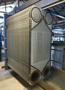
Plate heat exchanger dismantled pic02 216x300 1

In industrial field in various purposes “Plate and frame heat exchanger” is used. Inside the plate and frame heat exchanger the temperature and transferring of heat is always transfer from higher to lower.

In the industrial area the heat exchangers are used in a large quantity among them the Plate and frame heat exchanger is one of these.Plate and frame heat exchanger uses as a metal plate through which heat can be transfer between present of two fluids. It is carry a frame and clamped between a follower and head.

What is plate and frame heat exchanger?

Plate and Frame Heat Exchanger is a device which is most suitable heat exchanger for exchanging the pressure from low pressure to medium pressure by the medium of fluids of pressure. It is used in free cooling, boilers.

The plate and frame heat exchanger is a device which is uses in a sequence of metal plates where the heat is freely move one fluid to another fluid.  The plates of the plate and frame heat exchanger placed over each other thus it could create a sequence channel so the pressure fluid can move inside of it.

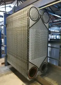
Plate and frame heat exchanger
Plate and frame heat exchanger Image Credit – Wikimedia Commons
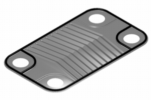
Individual plate of plate and frame heat exchanger
Image Credit – Wikipedia

How does plate and frame heat exchanger work?

The plate and frame heat exchanger is a device which is widely uses in small welded designs. The main convenience of the plate and frame heat exchanger is pressure fluid easily can distribute over metal plates.

The gaskets plates of the plate and frame heat exchanger cut down the heat through the surface of the exchanger and help in separate the medium of the hot to medium of the cold. For this reason lower temperature fluid, gas and higher temperature fluid, gas use minimal level of energy.

The working principle of the plate and frame heat exchanger is deeply derive in section of below,

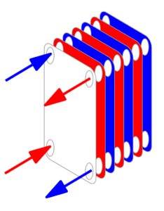
At the start of the process multiple plates are stack together.

Gaskets are used inside the plate and frame heat exchanger thus it could allow preventing fluids which are entering from the alternating plates. The gaskets can easily move left or right side for creating block. In every channel of the plates two fluids will definitely flow. The holes of the gaskets plates in the plate and frame heat exchanger align in this way from a pipe just like a channel from where fluid can flow.

If we go through the plate and frame heat exchanger’s gasket plates then we can observe that the alternates’ gasket plate side is block.

If cooler fluid can pass through the plate and frame heat exchanger then the fluid is entering from the left side top inlet.

After entering the cooler fluid it can flow through the plate 2, plate 4 and plate 6. After that the cooler fluid left a high temperature and discharge from the left side bottom outside.

In the next step the high temperature fluid enters through the right side of the lower inlet then it can flow through the plate 1, plate 3 and plate 5. After that the hot fluid discharges from the right side top outlet.

The gasket of the plate and frame heat exchanger is allowed to flow the fluid inside the particular channel.

In this process the plates which contained the channels from where fluids are flows with different temperature and it has always tendency to flow fluid from hot temperature to cold temperature.  

The higher temperature fluid transfers a little amount of thermal energy to the lower temperature fluid. The different type of two fluids never combines to each other and they never meet to each other just because of the separation is done by the wall of the metal plate. For this reason the lower temperature fluid was getting hot and lower temperature fluid getting cold. The amount of exchange the heat in the plate and frame heat exchanger is simple type.

We should always ensure that, the protective sleeves need to attach with the tightening bars over the threads. Insulated should be kept more thermal energy.

The flow of the fluid is counterflow.

The counterflow working principle is most effective only because of log mean difference of temperature. Logarithmic average of the temperature difference (LMTD) is greatest.

Types of plate and frame heat exchanger:

The plate and frame heat exchanger can be classified into four categories. They are,

  1. Brazed plate and frame heat exchanger
  2. Gasketed plate and frame heat exchanger
  3. Welded plate and frame heat exchanger
  4. Semi welded plate and frame heat exchanger

The types of plate and frame heat exchanger classifications description is given below,

Brazed plate and frame heat exchanger:

The structure of the brazed plate and frame heat exchanger is carry both equipment name gasket and frame. Brazed plate and frame heat exchanger mainly use for small applications but now a day’s brazed plate and frame heat exchanger widely for the large applications. In refrigeration and automotive sector it is use mainly.

In the brazed plate and frame heat exchanger use stainless steel and copper brazing is used to make its plates for this reason it have high corrosion resistive characteristics. This Brazed plate and frame heat exchangers are very lightweight and efficient for this reason this type of heat exchanger is economical.

Brazed plate and frame heat exchanger contain thin metal plates to isolate the pressure fluid, but the metal blades all together to make a full seal. The seal of this heat exchanger is formed with the help of positioning and brazing of the metal plates by which the fluid will be flow can be determined. It contains both high pressure and higher temperature.

The benefits of using brazed plate and frame heat exchanger is,

  1. Exchangers are used.
  2. Low maintenance cost.
  3. Design of construction is easy.
  4. Heat loss is very minimum.

Gasketed plate and frame heat exchanger:

In gasketed plate and frame heat exchanger multiple thin metal sheets are use to make the structure of channel. The heating or cooling capacity can be increases or decreases by adding or subtracting the internal thin metal sheets. The purpose for repair or washing it can also disassemble. The metals which are use to made the thin plates are stainless steel, platinum, and mild steel. In gasketed plate and frame heat exchanger gaskets are made of rubber.

In process engineering, automotive sector, heavy duty HVAC the gasketed plate and frame heat exchanger widely used.

Read more about SUPERHEAT HVAC : IT’S IMPORTANT CONCEPTS AND 3 FAQS

The benefits of using gasketed plate and frame heat exchanger is,

  1. Low maintenance cost.
  2. Leakage can easily prevent.
  3. Replacement of expansion valve is not difficult.
  4. Cleaning of the thin metal plates is not facing difficulty.

Welded plate and frame heat exchanger:

If we looked upon the structure of Welded plate and frame heat exchanger then we can observe the inside structure is so similar with gasketed plate and frame heat exchanger.

The benefits of using welded plate and frame heat exchanger is,

  1. Loss of fluid is very less.
  2. It is highly robust type.
  3. Corrosive or hot fluid can easily move in it.

Semi welded plate and frame heat exchanger:

With the help of two plate’s pair the internal metal plates are made of and they are welded. Another pairs of the gasketeds one pair is welded for making fluid path and another pair is gasketed for making fluid path.

The benefits of using semi welded plate and frame heat exchanger is,

  1. Loss of fluid is very less.
  2. Moving of heavy materials is not facing difficulty.

Plate and frame heat exchanger diagram:

The diagram of the Plate and frame heat exchanger is given below,

Plate and frame heat exchanger
Plate and frame heat exchanger diagram
Image Credit – Wikipedia

Plate and frame heat exchanger applications:

The application of plate and frame heat exchanger are given below,

  1. Heat pump isolation
  2. Water heaters
  3. Waste heat recovery
  4. Free cooling
  5. Cooling tower isolation

Heat pump isolation:

For protecting the heat pump from the contaminants in the supply of water graham plate series exchanger are used. High degree of turbulence cab be easily maintain by graham plate series exchanger, which reducing fouling and appropriate for flowing the higher temperature fluid.

Water heaters:

Stainless steel is used to make water heater. It has high rate of heat transfer and resistivity in corrosion.  In water heater mainly graham plate exchanger are used which is appropriate for flowing the higher temperature fluid.

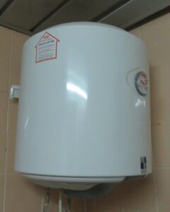
Water heater
Water heater
Image Credit – Wikipedia Commons

Waste heat recovery:

Waste heat can be generated help of chillers, steam condenser, and many others process is used to making heat of air or water. High efficiency and lower temperature it helps to reduce energy cost.

Free cooling:

For the operation of free cooling chillers of the refrigeration system is shut down and helps to reducing the cost of plant utility. In the free cooling graham plate exchanger are used. During the free cooling process the air is pre cool by the help of cooling tower water.

Cooling tower isolation:

By the help of cooling tower isolation the cooling water is circulated in the buildings. . In the cooling tower isolation graham plate exchanger are used to minimize the turbulence of the water.

Cooling tower
Cooling tower
Image Credit – Wikipedia Commons

Plate and frame heat exchanger sizing:

For the measuring process of Plate and frame heat exchanger sizing is followed some steps. They are,

  1. Get the data of design
  2. Calculating the flux of the heat
  3. Calculating the needed number of thin plates
  4. Confirmation the size of the heat exchanger

Get the data of design:

At the beginning for calculating the size of the plate and frame heat exchanger the first step need to follow is get the data of design. The data which are should to follow to run this process is listed below,

  • Properties present in the fluids.
  • Temperature for each and every fluid in the outlet and inlet.
  • Pressure for the fluid in the inlet.
  • Allowable pressure drop.

Calculating the flux of the heat:

If flowrate of the flowing fluid, specific heat, inlet temperature, outlet temperature or either know the cold side or hot side then heat flux can be easily calculated.

With the help of the formula from which heat flux can be calculated is given below,

gif

Where,

mc = Mass flow rate on the lower temperature side in kg per second

Cpc= Specific heat on the lower temperature side

T2= Outlet temperature on the lower temperature side in Kelvin

T1= Inlet temperature on the lower temperature side in Kelvin

h = Mass flow rate on the higher temperature side in kg per second

Cph= Specific heat on the higher temperature side

T4 = Outlet temperature on the higher temperature side in Kelvin

T3 = Inlet temperature on the higher temperature side in Kelvin

By the help of Heat transfer coefficient heat flux can be determined.

gif

Where,

H = Overall heat exchange coefficient in kw.m2.K-1

S = Area of the heat exchanger in square meter

Calculating the needed number of thin plates:

The needed number of thin plates can determined using this formula,

N = S/s

Where,

N = Needed number of thin plates

S = Total area of the heat exchanger area in square meter

s = Size of a particular single plate in square meter

Confirmation the size of the heat exchanger:

Usingthe Nusselt number the size of the heat exchanger can be determined.

Where,

Nu = Nusselt number

a = Coefficient depending upon the corrugation of plate

Re = Reynolds number

b = Coefficient depending upon the corrugation of plate

Pr= Prandtl number

Prw = Prandtl number at the wall of the plate

Read more about Reynolds number : It’s 10+ Important facts

Plate and frame heat exchanger cleaning and maintenance:

Plate and frame heat exchanger cleaning and maintenance done in three steps. They are listed below,

  1. Scheduled maintenance
  2. Clean in place
  3. Manual maintenance

Scheduled maintenance:

The common process of maintaining Plate and frame heat exchanger cleaning and maintenance is scheduled maintenance. In this process scheduled and regularly maintain and cleaning the apparatus of the heat exchanger. These kinds of cleaning and maintenance process at least stay for six months.

Clean in place:

In this process periodically maintain and cleaning the apparatus of the heat exchanger. This kind of cleaning and maintenance process the plate not need to open it helps to drop excessive pressure inside the heat exchanger.

Manual maintenance:

In this process annually maintain and cleaning the apparatus of the heat exchanger. This kind of cleaning and maintenance process at least stays for more than one year.

Vapor Compression Cycle: What, How, Types, Working, Applications and Various Facts:

Refrigeration 1

In this article ”Vapor compression cycle ” is discuss and vapor compression cycle related facts are also summarize briefly. The vapor compression cycle is commonly used is the system of refrigeration.

In the system of refrigeration which follows the cycle of thermodynamic, is used in a wide range. The energy of heat is transforming from a cold reservoir and after that transfer into a hot reservoir. In a closed cycle fluids is used and go through compression, condensation, and expansion, evaporation process.

What is vapor compression cycle?

The Vapor compression cycle is used in automobile and refrigeration industry. Chilling the storage food items and meat in the warehouses, oil refineries, chemical processing plants many others it is widely used.

The Vapor compression cycle explain as a liquid refrigerant is uses which rotate circularly in the system and works as a medium. The liquid refrigerant absorb the heat from any particular space where cooling is needed and also can remove heat from any particular space where heating is needed for the system.

Vapor compression cycle
Image – Vapor Compression Cycle
Image Credit – Wikipedia Commons

The vapor compression cycle is done in a closed cycle. In the system of vapor compression cycle the fluid which is work as a medium is actually a vapor. In a very speedy mode the fluid is evaporate and changes itself alternatively between the liquid phase and vapor or condenses inside of refrigerating plant.

Vapor compression cycle diagram:

The Vapor compression cycle the liquid refrigerant changes its state of phase for two times. In first step liquid refrigerant change itself liquid to vapor and in next step change itself vapor to liquid.

The Vapor compression cycle diagram can be explain as help of two diagrams which is given below,

Pressure – Volume diagram

512px Refrigeration PV diagram.svg
Image – Pressure – Volume diagram; Image Credit – Wikipedia

Temperature –Specific entropy diagram

RefrigerationTS
Image – Temperature –Specific entropy diagram;
Image Credit – Wikipedia

Vapor compression cycle process and working principle:

The Vapor compression cycle is a method which is most commonly used in various fields because its cost of charge is very low and the construction of the vapor compression cycle is quite easy to establish.

The cycle process of vapor compression in refrigeration system is working based on reverse Rankine cycle. The Vapor compression cycle process is proceeding in four steps. They are listed below,

Vapor Compression Cycle
Image – Vapor compression cycle process and working principle
Image Credit – Wikipedia Commons
  1. Compression
  2. Condensation
  3. Throttling
  4. Evaporation

In this below section the four steps are discusses,

Compression (Reversible adiabatic compression):

The refrigerant of vapor compression cycle at low temperature and pressure stretched from evaporator to compressor where the refrigerant is compressed isentropically. The pressure is rises from p1 to p2 and temperature is rises from T1 to T2. The total work done per kg of refrigerant happened during isentropic compression can be express as,

w = h2 – h1

Where,

h1 = Amount of enthalpy of vapor compression cycle in temperature T1, at the step of suction of compressor

h2 = Amount of enthalpy of vapor compression cycle in temperature T2, at the step of discharge of compressor.

Condensation (Constant pressure heat rejection):

The refrigerant of vapor compression cycle is passes through from compressor to condenser at high temperature and pressure. At constant pressure and temperature the refrigerant is completely condensed. The refrigerant changes its state from vapor to liquid.

Throttling (Reversible adiabatic expansion):

At high temperature and high pressure the refrigerant of vapor compression cycle is expanded through the process of throttling. That time the expansion valve is stays in low temperature and pressure. A little amount of liquid refrigerant is evaporating by the help of expansion valve and a huge amount of liquid refrigerant is vaporised by the help of evaporator.

Evaporation (Constant pressure heat addition):

The refrigerant mixture of vapor and liquid is completely evaporated and changed itself into vapor refrigerant. During this evaporation process the refrigerant is absorb latent heat which state is cool. The amount of latent heat absorption by the refrigerant in vapor cycle is known as Refrigerating effect.

Performance of vapour compression cycle in the refrigeration system:

The vapour compression cycle in the refrigeration system is working at evaporator in the law of Steady Flow Energy Equation,

h4 + Qe = h1 + 0

Qe = h1 – h4

The vapour compression cycle in the refrigeration system is working at condenser in the law of Steady Flow Energy Equation,

h2 + Qc = h3 + 0

Qc = h3 – h2

The vapour compression cycle in the refrigeration system is working at expansion valve in the law of Steady Flow Energy Equation,

h3 + Q = h4 + W

We know, value of Q and W is 0

So, we can write,

h3 = h4

Performance of vapour compression cycle in the refrigeration system is,

Output/Input = h1 – h4/h2 – h1

What is simple vapor compression cycle?

The simple vapor compression cycle air is used as a refrigerant and it is evaporate at very low temperature and low pressure. The mechanical energy is required to run the compressor of the system.

The simple vapor compression cycle can be explain as the heat engine which is works in reverse technically that can be known as Reverse Carnot engine. The simple vapor compression cycle transfer heat from lower temperature reservoir to higher temperature reservoir.

What is vapor compression cycle of a refrigeration system?

The vapor compression cycle of a refrigeration system is one of the most common used and popular refrigeration systems among the all refrigeration system. For both domestic and industrial purpose vapor compression cycle of a refrigeration system is used.

The vapor compression cycle of a refrigeration system is belong to the refrigeration cycle which is mainly general class type and in this system the refrigerant is undergoes phase chance , minimum during one process. The cycle is working in a closed system and refrigerant is moves in a circular motion.

In vapor compression cycle NH­3, R – 12, R- 11 refrigerant are uses. The vapor compression cycle of a refrigeration system consists of refrigerant compressor, liquid compressor, liquid receiver, evaporator and expansion valve which are known as refrigerant control valve.

Vapor absorption refrigeration cycle:

The vapor absorption refrigeration cycle can work easily where high power is not available. The main difference between vapor compression cycle and vapor absorption refrigeration cycle is compressor is replaced.

In the vapor absorption refrigeration cycle lowering the temperature of the system which is done in a closed system, refrigerant work as medium and removing unwanted heat from any particular space of the system and after removing transfer the heat where temperature is lower in the refrigeration system.

Read more about Saturated Suction Temperature : Need to know Critical Facts

In the vapor absorption refrigeration cycle generator, pressure reducing valve, expansion valve, condenser pump and absorber is used.  Ammonia is use in the system as a refrigerant and the mixture of ammonia, lithium bromide, water and water is used as an absorbent.

Ideal vapor compression cycle:

Ideal vapor compression refrigeration cycle system at first refrigerant enter into the compressor as a saturated vapor after that the refrigerant became cool to the liquid state of saturated inside the condenser. When the throttling process is happened in the evaporator vapour and pressure is absorb in the refrigerate space.

Simple vapor compression cycle:

Simple vapor compression cycle refrigeration cycle systems at first refrigerant enter into the compressor as a vapor at lower pressure. After that the refrigerant became superheated at higher pressure inside the condenser. When the throttling process is happened in the heat is release and enters to next process of the cycle.

Read more about Superheat Hvac : IT’S IMPORTANT CONCEPT AND 3 FAQs

Actual vapor compression cycle:

Actual vapor compression cycle refrigeration cycle is not same process as the theoretical vapor cycle of process. In the actual vapor compression cycle loss and unavoidable vapor is present.  The refrigerant leaves the evaporator in the state of superheat.

Read more about Superheat Refrigeration : Its All Important 4 notes

Vapor absorption cycle:

Vapor absorption cycle in the refrigeration system can be describe as refrigerant condensed in the condenser and evaporate at evaporator. In this all refrigeration system process are present such as compression, condensation and expansion evaporation. As a refrigerant lithium bromide, water or ammonia can be used.

Vapor absorption cycle applications:

Application of vapor absorption cycle in refrigeration system is given below,

Domestic refrigeration:

 In dwelling units food is storage in domestic refrigeration.

Cold storage and Food processing:

For processing, preserving and storage food items from its origin of source to the distribution point of the wholesale distributions.

Commercial refrigeration:

Displaying and holding fresh and frozen food items in retain outlet.

Medical refrigeration:

For keeping the medicine in right temperature medical refrigeration is used.

Electronic cooling:

For controlling temperature in large computers, CMOS circuit (Complementary metal–oxide–semiconductor)electronic cooling is used.

Vapor absorption cycle working principle:

The Vapor absorption cycle working principle is summarize in below,

  1. At beginning of the process vapour comes from evaporator and then go to absorber and vapour is absorbed in water.
  2. During the process of absorbing latent heat and heat of mixing is emitted.
  3. Cooling process is done by the absorber to keep the temperature lower in the system.
  4. Absorbing capacity is increases when the absorber is in lower temperature.
  5. Strong aqua mixture of ammonia and water is comes from the absorber and go to the top of the analyzer with the help of pump through aqua heat exchanger.
  6. By the generator the aqua falls mixture is sent to analyzer. In the generator higher temperature is present for this reason low boiling ammonia easily can be separate from the mixture.
  7. The heating process of the generator can be done with the help of solar energy, steam energy or electric energy. In this time ammonia vapour is raises by the analyzer.
  8. During this process wet vapour became dry vapour and sent to the condenser by rectifier.
  9. Water is separated. After separation water is again back to generator this known as Drip. Anhydrous ammonia vapour only goes to the condenser. Liquid ammonia go from condenser to evaporator through the valve of expansion for continue the cycle.
  10. When the aqua mixture is hot it became weaker and comes to evaporator of the system through the heat exchanger. The weak hot aqua again absorbs the vapour of ammonia and cycle stays in continue.
  11. Heat exchanger of the aqua heat the strong aqua mixture and pass to the generator in this process heat is reduced in the heating materials in the generator.

Vapor absorption cycle processes:

Vapor absorption cycle process is done by four steps.

Compression process:

In first of the vapor absorption cycle process compression process is done. In this process vapour stays at very low pressure and temperature.  The vapour is enters to the compressor when it is compressed subsequently and isentropically. After this both temperature and pressure are increases.

Condensation process:

After completing the process in compressor vapour enter to condenser. The vapour is condensed in the high pressure and goes to the receiver tank.

Expansion process:

After completing the process in condenser vapour enter to expansion valve from receiver tank. The throttling process is done in the low pressure and low temperature.

Vaporization process:

After completing the process in expansion valve vapour enter to evaporator. In the evaporator the vapour is extracts heat and circulating fluid in the surrounding environment and in lower pressure vapour is vaporized.

If without throttling expansion is takes place then the level of temperature will be drop in very low temperature and undergoes sensible heat, latent heat to particularly reach to stage of evaporation.

Difference between vapor compression and absorption cycle:

The vital difference between vapor compression and absorption cycle is Coefficient of performance vapor compression is high and for vapor absorption refrigeration cycle Coefficient of performance is low.

In below briefly the Difference between vapor compression and absorption cycle is given,

Particular Vapor compression cycle of a refrigeration system Vapour absorption refrigeration cycle of a refrigeration system
Coefficient of performance(COP) High, range is about 0.3 Low, range is about 0.6
Noise Very high operation Quiet operation
Wear and Tear High, because moving parts are more present in the system of the compression. Low, because moving parts are less present in the system of the absorption.
Bulkiness More less More
Presence of shelter Cannot situated in outside of the system without shelter Can be situated in outside of the system without shelter
Affected by loads Too much Reduction of load no effect
Leakage possibility More Less
Charging of refrigerant Simple Complicated
Working of high grade energy High, electrical energy is needed to precede the operation. Low, electrical energy is not needed to precede the operation, by the help of Ignition combustion engine, process heat or kerosene lamp the vapour absorption refrigeration cycle of a refrigeration system can work.
Operating cost High Less
Capacity Less, upto 1000 tons More, above 1000 tons
Suitable refrigerant NH­_3, R – 12, R- 11 Ammonia
Energy supplied as input Mechanical Heat energy
Condition of refrigerant Compressed Absorbed and heated.
Supply of energy Low High
Maintenance cost High Low
Pressure High Low
Work capacity Limited Large

Frequent Asked Question:-

Question: Write down the advantages of Vapor Compression refrigeration cycle.

Solution: The advantages of Vapor Compression refrigeration cycle is listed below,

  1. Coefficient of performance is too high.
  2. Size is not too big for this reason installation is easy.
  3. Running cost is low.
  4. Temperature can be easily handled by the help of regulating expansion valve.
  5. Evaporator size is not big.

Question: Write down the disadvantages of Vapor Compression refrigeration cycle.

Solution: The disadvantages of Vapor Compression refrigeration cycle is listed below,

  1. The refrigerants which are used they are toxic.
  2. Initial cost is high.
  3. Leakage is present.

­5 Partial Pressure Example: Detailed Explanations

In this article ”Partial pressure example” is discuss and also gave a brief description about partial pressure example. From the law of Dalton’s we can get a clear idea about partial pressure example. 

6+ partial pressure examples and their detailed explanations are mention in below,

  1. Fire extinguisher
  2. Aerosol cans
  3. Opening soda cans
  4. Flying of jet aeroplanes
  5. Pressure is calculated of a dry gas
  6. Examine patient’s blood

Fire extinguisher:

The common example of partial pressure is fire extinguisher which is device used for as an active fire protection. The fire extinguisher device mainly used for to control small or extinguish fire. When fire extinguisher is uses in the field before that we should have clear concept about how it should to use and which type suitable in the particular field.

A fire extinguisher is containing a long cylinder. At the top the long cylinder an operating lever is placed. A tube which is filled with carbon dioxide is present inside the cylinder and around it surrounding amount of water is present for this reason pressure is create around the tube of carbon dioxide.

A siphon tube is present in the cylinder of fire extinguisher. The siphon tube is going in the horizontally of the cylinder and open with the water near the section of the bottom. In other side of ending a chamber is placed which have mechanism of spring and connected with discharge valve of the carbon dioxide tube.

The mixture of carbon dioxide and water does not contain the whole cylinder. Head space is present in the cylinder for this reason the area of the cylinder fill with air. The operating lever when stooping that time the spring mechanism is working and discharge valve is open which is situated at top section of carbon dioxide tube. At the stage when discharge valve is open dioxide comes at the area of head space and water is exerted by pressure. The mixture is comes out by the help of siphon tube and fire extinguisher start to working.

Partial pressure example
Image – Fire extinguisher
Image Credit – Wikimedia Commons

Aerosol cans:

An Aerosol cans structure is most of similar to fire extinguishers. Inside the Aerosol cans a tube is present and it also contains the spring mechanism as same as fire extinguisher and comes out with help of a tube. The main difference between the aerosol cans and fire extinguisher is instead of gas liquid propellant is present.

aerosol
Image – Aerosol can
Image Credit – SnappyGoat.Com

Opening soda cans:

Inside a soda can carbon monoxide is present among them maximum are dissolved in the drink by itself.  But some carbonated soda takes a space for this particular reason difference is appear in the volume of the jar and volume of the drink of soda.

In the plant of the blotting carbon dioxide is added in the soda can which should carry high pressure to create a head space to confirm that more amount of carbon dioxide should be absorb in the soda by itself.

Flying of jet aeroplanes:

The jet aeroplanes works in the principle of partial pressure. With the help of propeller powered aircraft the maximum efficiency can achieve the jet planes. The response of the jet planes is not too higher. 

When the jet discharge gas ignites back the jet aeroplanes can move forward itself.

Pressure is calculated of a dry gas:

In a dry gas with the help of partial pressure the total amount of pressure can be calculated.

Examine patient’s blood:

For surviving oxygen is needed for human body. Humans are exposed constantly changes in Blood Pressure, that can be naturally or artificially, for this particular reason pressure inspired oxygen and it is indirectly proportional to reduction among exposed to normobaric hypoxia or hypobaric.

Frequent Asked Question:-

Question:  Explain Dalton’s law where partial pressure example works.

Solution: From the law of Dalton’s we get a clear concept about the partial pressure of a matter.

The law of Dalton of a partial pressure is explain as, the total amount of pressure is exerted by externally by a compound of gasses substance is equal to total amount of partial pressure which is exerted by each every particular gas in the compound.

Suppose in a jar two types of gas carbon monoxide and oxygen is present and makes a mixture. Then the total amount of pressure exerted in the compound gas of car monoxide and oxygen is sum is equal to their individual partial pressure which is exerted by gas car monoxide and gas oxygen.

Formula of Dalton’s law:

The formula of Dalton’s law can be written as,

Where,

Ptotal = The total amount of pressure which is exerted by the compound of gas

R = Universal gas constant

T = Temperature in Kelvin

V = Volume of the matter

Question:  Which factors are affected the partial pressure and how they are related to each other describe it?

Solution: The factors which are affected the partial pressure is listed below,

  1. Temperature
  2. Pressure
  3. Total amount of gas which is measure by mole number

Temperature:

The relation between the temperate and partial pressure is directly proportional each other. Means if the rate of temperature is increases of a matter for this case the partial pressure is also increases, and if the rate of temperature is decreases of a matter for this case the partial pressure is decreases.

TEMPERATURE 11
Image – Temperature
Image Credit – SnappyGoat.Com

Pressure:

The relation between the pressure and partial pressure is indirectly proportional to each other. Means if the rate of pressure is increases of a matter for this case the partial pressure is decreases, and if the rate of temperature is decreases of a matter for this case the partial pressure is increases.

350px Pressure force area.svg
Image – Pressure
Image Credit – Wikipedia

Read more about Pressure Vessel : It’s important facts and 10+ applications

Total amount of gas which is measure by mole number:

The relation between the total amount of gas which is measure by mole number and partial pressure is directly proportional each other. Means if the rate of total amount of gas which is measure by mole number is increases of a matter for this case the partial pressure is also increases, and if the rate of total amount of gas which is measure by mole number is decreases of a matter for this case the partial pressure is decreases.