9+ Heat Exchanger Examples: Detailed Facts

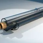
220px Tubular heat exchanger 150x150 1

This article discusses about heat exchanger examples. The name makes it easier for us to understand the meaning of heat exchanger.

The heat exchanger is nothing but an equipment that exchanges heat between two substances in order to bring down or elevate the temperature to desired levels. In this article we shall study about what a heat exchanger is, what are its different types and different examples where heat exchangers are used.

What is heat exchanger?

Heat exchanger is an equipment used to transfer heat between the working fluid and the fluid whose temperature is to be brought down or increased.

Heat exchangers uses hollow tubes through which the fluids are passed. The fluids have temperature difference between them due to which heat transfer takes place. The most important thing for heat transfer to take place is temperature difference between the two objects/fluids. In this article we shall discuss about the different types of heat exchangers and their examples.

heat exchanger examples
Image: Tubular heat exchanger

Image credits: Wikipedia

Types of heat exchangers according to the direction of flow of fluids

According to the direction of flow of fluids relative to each other, we can classify heat exchangers in to three types. These types are given in the list below-

  1. Parallel flow heat exchanger- When the fluids flow in the same direction relative to each other, the heat exchanger will be referred to as parallel flow heat exchanger. The temperature of the hot fluid decreases whereas the temperature of cold fluids increases.
  2. Counter flow heat exchanger- When the fluids flow in opposite direction relative to each other, then the heat exchanger will be referred to as counter flow heat exchanger. We can find the effectiveness of the heat exchanger using the formula discussed in the later sections of this article.
  3. Cross flow heat exchanger- As the name suggests, cross flow heat exchangers are those heat exchangers in which the fluids flow perpendicular to each other. The tubes make ninety degrees to each other.

Types of heat exchangers according to the transfer process

The classification of heat exchangers on the basis of transfer processes are given in the list below-

  1. Indirect contact type- In this type of arrangement, the fluid streams separate and the heat transfer takes place continuously through a dividing wall in and out of the wall in a transient manner. Different types of indirect contact type heat exchangers include storage type heat exchanger, fluidized bed heat exchanger etc.
  2. Direct contact type– In the direct contact type heat exchanger, two fluids exchange heat with each other by coming in direct contact with each other. They exchange heat and then get separated from each other.

Effectiveness of Heat exchanger

The effectiveness of heat exchanger is a ratio between the actual heat transfer taking place to the maximum heat transfer that can take place in the heat exchanger.

The significance of effectiveness is that it allows the designers to predict how a given heat exchanger will perform a new job. The trial and error procedure is eliminated if we know the effectiveness of the heat exchanger.

Heat exchanger examples

The places where heat exchangers are used are given in the list below-

Air pre heaters

The name suggests that the air is being heated prior to sending it to perform any other process. For examples, they can be used in boilers for increasing the thermal efficiency of the power plant. Pre heated air will improve the quality of fuel input into the power plant.

Economizers

It is an alternative to the air conditioning system. Economizers use outside air to cool the building instead of running compressors like those used in air conditioning system. This also saves a huge sum of money as it saves energy.

Evaporators

Evaporators are used to convert any liquid to its gaseous form. The temperature of the liquid remains the same. The phase change process is an isothermal process. The evaporators are used in boilers to change the liquid water to gaseous steam. In evaporators, the temperature of fuel is same as it undergoes phase transformation. On the other hand the temperature of the colder fluid increases that is used as working fluid inside the heat exchanger.

Superheaters

Superheaters are used inside boilers that convert the wet steam to dry steam. The dry steam is that steam in which there is no liquid water content. The dryness fraction of dry steam is 1 or 100%. The superheaters are used for superheating the steam. The quality and enthalpy of superheated steam is greater than the normally used wet steam or saturated steam.

Condensers

Condensers are opposite to what evaporators are. Condensers bring back the liquid from its gaseous state without changing its temperature. The condensers are simple heat exchangers that absorb heat from the steam and convert it back to liquid water. The amount of heat absorbed is equal to the latent heat of vapourisation of water. Similar to the evaporators, the fuel’s temperature remains the same and the temperature of hot fluid that is used as working fluid inside the heat exchanger decreases.

Cooling towers

A cooling tower is a tower used to reject heat from the system to the surroundings. The heat expelled out of the system is waste heat that holds no use in the further process. These towers appears as chimneys through which a cloud of gas is expelled out. This gas cloud is nothing but the gas of working fluid. Heat is being dissipated in the form of steam.

Swimming pool heat exchanger

A swimming pool heat exchanger transfers heat from a hot water stream to the cooler pool water stream without making them come in direct contact to each other.

Hydraulic oil cooler

A hydraulic oil cooler cools the hydraulic oil. These can be used in power packs, power washers and engines, almost anywhere the hydraulic oil is used. The hydraulic oil needs to be cooled because without cooling, the oil may catch fire due to higher temperatures and may be fatal for the operator as well as the machinery.

Boilers

The most common use of heat exchangers is in boilers. The boilers use heat exchangers to heat the liquid water such that it gets converted in to steam. In the entire phase change process, the temperature of the liquid/gas remains the same meaning it is an isothermal process. We have already discussed in the above sections how heat exchangers work inside a boiler.

Water jackets

In water jackets, water is used to cool or heat the exhaust running through the engine. We can see jacketing in rocket engines, the hot exhaust gases heat up the fuel and then the fuel is sent back for combustion. This increases the combustion efficiency of the rocket engine. In automobiles, water jacketing is used to cool the engine and prevent excessive heat loss. The water jacketing brings down the engine temperature.

Other types of heat exchangers

On a broader basis, there are many more types of heat exchangers. They are given in the list below-

  • Shell and Tube heat exchangers
  • Plate heat exchanger
  • Plate and shell heat exchanger
  • Adiabatic wheel heat exchanger
  • Finned tube heat exchanger
  • Pillow plate heat exchanger

The Rotational Kinetic Energy of the Earth: A Comprehensive Guide

rotational kinetic energy of earth

The rotational kinetic energy of the Earth is a fundamental concept in physics, representing the energy the Earth possesses due to its rotation around its axis. This energy can be calculated using a specific formula and is influenced by various factors, including the Earth’s mass, radius, and angular velocity. Understanding the rotational kinetic energy of the Earth is crucial for understanding the Earth’s dynamics and its interactions with other celestial bodies.

Understanding the Rotational Kinetic Energy Formula

The formula for calculating the rotational kinetic energy of the Earth is:

KE = 0.5 * I * ω^2

where:
KE is the rotational kinetic energy of the Earth (in Joules)
I is the moment of inertia of the Earth (in kg·m²)
ω is the angular velocity of the Earth (in radians per second)

The moment of inertia of a solid sphere, such as the Earth, rotating about its diameter is given by:

I = (2/5) * M * R^2

where:
M is the mass of the Earth (in kg)
R is the radius of the Earth (in meters)

Calculating the Rotational Kinetic Energy of the Earth

rotational kinetic energy of earth

To calculate the rotational kinetic energy of the Earth, we need to substitute the known values into the formulas.

The relevant values for the Earth are:
– Mass (M) = 5.97 × 10^24 kg
– Radius (R) = 6.371 × 10^6 m
– Angular velocity (ω) = 7.27 × 10^-5 rad/s

Substituting these values into the formulas, we get:

I = (2/5) * M * R^2
I = (2/5) * (5.97 × 10^24 kg) * (6.371 × 10^6 m)^2
I = 8.04 × 10^37 kg·m²

KE = 0.5 * I * ω^2
KE = 0.5 * (8.04 × 10^37 kg·m²) * (7.27 × 10^-5 rad/s)^2
KE = 2.54 × 10^29 J

Therefore, the rotational kinetic energy of the Earth is approximately 2.54 × 10^29 Joules.

Factors Affecting the Rotational Kinetic Energy of the Earth

The rotational kinetic energy of the Earth is influenced by several factors:

  1. Mass: The mass of the Earth directly affects the moment of inertia and, consequently, the rotational kinetic energy. A more massive Earth would have a higher rotational kinetic energy.

  2. Radius: The radius of the Earth also plays a crucial role in determining the moment of inertia and the rotational kinetic energy. A larger Earth radius would result in a higher rotational kinetic energy.

  3. Angular Velocity: The angular velocity of the Earth’s rotation is a key factor in the rotational kinetic energy calculation. A faster rotation would lead to a higher rotational kinetic energy.

  4. Gravitational Interactions: The gravitational forces exerted by the Moon and the Sun can cause a gradual decrease in the Earth’s rotational kinetic energy over time. This is due to the transfer of energy from the Earth’s rotation to its orbital motion.

Practical Applications of Rotational Kinetic Energy

The understanding of the Earth’s rotational kinetic energy has several practical applications:

  1. Satellite Dynamics: The rotational kinetic energy of the Earth affects the dynamics of satellites orbiting the planet, as it influences the gravitational forces acting on the satellites.

  2. Tidal Forces: The rotational kinetic energy of the Earth is related to the tidal forces experienced on the planet, which are caused by the gravitational interactions between the Earth, the Moon, and the Sun.

  3. Geophysical Measurements: Measurements of the Earth’s rotational kinetic energy can provide insights into the planet’s internal structure and composition, as well as its overall dynamics.

  4. Time Measurement: The Earth’s rotation is used as a reference for timekeeping, and changes in the rotational kinetic energy can affect the accuracy of time measurements.

Conclusion

The rotational kinetic energy of the Earth is a fundamental concept in physics that provides valuable insights into the Earth’s dynamics and its interactions with other celestial bodies. By understanding the formula, the relevant factors, and the practical applications of this energy, we can gain a deeper understanding of our planet and its place in the universe.

References

  1. “Is the rotational KE of a rigid body considered as internal energy?”. Physics Forums. https://www.physicsforums.com/threads/is-the-rotational-ke-of-a-rigid-body-considered-as-internal-energy.985436/
  2. “Rotational kinetic energy when moment of inertia is changed”. Physics Stack Exchange. https://physics.stackexchange.com/questions/331621/rotational-kinetic-energy-when-moment-of-inertia-is-changed
  3. “10.4 Moment of Inertia and Rotational Kinetic Energy”. Suny Osuniversity Physics. https://courses.lumenlearning.com/suny-osuniversityphysics/chapter/10-4-moment-of-inertia-and-rotational-kinetic-energy/
  4. “What is the rotational kinetic energy of the earth? Assume the earth is a uniform sphere. Data for the earth can be found inside the back cover of the book.”. Vaia. https://www.vaia.com/en-us/textbooks/physics/physics-for-scientists-and-engineers-a-strategic-approach-with-modern-physics-4th/rotation-of-a-rigid-body/q-10-what-is-the-rotational-kinetic-energy-of-the-earth-assu/
  5. “10.23 | (a) Calculate the rotational kinetic energy of Earth on its axis …”. OpenStax Physics. https://www.youtube.com/watch?v=5LRis7-Vqa4

What Does A Crankshaft Sensor Do: How It Works

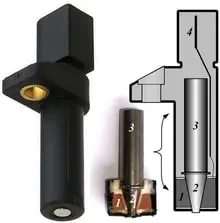
220px Crankshaft sensor

This article answers the question- what does a crankshaft sensor do? Crankshaft sensor is a device used in internal combustion engines to locate the position of crank and its velocity.

We shall discuss the working of an internal combustion engine first, then we shall continue our discussion further with crankshaft sensor and the working of crankshaft sensor. In later sections, we shall also read about different types of internal combustion engines.

What is an IC engine?

An internal combustion engine or IC engine is a heat engine inside which combustion takes place with the help of an oxidizer and working fuel.

IC engine converts this heat energy produced by the combustion of fuel-air mixture to mechanical energy. The main parts of IC engine include Piston, Cylinder, Crank, Spark plugs (In SI engine), crankshaft. We shall discuss more about internal combustion engines in the next section. 

Working of internal combustion engine

Internal Combustion engine is an assembly of various mechanical components that work in harmony to produce desired output.

During the intake stroke, the fuel is injected in the system. The piston is connected to connecting rod that connects piston and the crank. As the air fuel mixture is ignited, the piston moves at the bottom dead center and then comes back to the top dead. Due to reciprocating motion of the piston, the crank rotates and in turn helps the wheels to rotate.

How does a crankshaft sensor work?

A crankshaft sensor can be attached to an engine block facing towards the timing rotor or the ring gear attached on the crankshaft. The crankshaft has teeth whose positions are used to determine the actual position of crankshaft.

The sensor will keep a count of the number of teeth that have passed on the ring gear. This information is fed to the engine control unit or engine management system which then calculates the precise position of the crankshaft and decides when the switching on and off of different spark plugs.

what does a crankshaft sensor do
Image: Different crankshaft position sensors

Image credits: TamasflexCrankshaft sensorCC BY-SA 3.0

Crankshaft sensor use

The uses of crankshaft sensor are not many but every use is a very significant one. The uses of a crankshaft sensor are given in the section below-

  • Count the number of teeth passed and feed the information to the engine management system.
  • Locate the position of crankshaft.
  • The information about the position of crankshaft is then used to decide the switching on and off of different spark plugs.

Causes of crankshaft sensor failure

There are many causes of failure for a crankshaft sensor. The causes include the following-

  1. Damage– Due to a sudden jerk or excess pressure on the sensor, the sensor may get damaged. Some times the heat gets inside the sensor and melts few components. Such damages lead to crankshaft failure.
  2. Debris – Debris from other broken components can hinder the reading collection process and may lead to crankshaft sensor failure.
  3. Faulty circuitry– When the circuit connections are not proper, the readings from sensor will not be able to reach the engine management system. The sensor will not able to find the correction position of the crankshaft drive and hence the firing order of spark plugs will be uneven leading to more fuel consumption.

How are crankshafts made?

The crankshafts are usually made of steel. The manufacturing processes may vary but commonly they are made using die forging. If the material is cast iron then they are made by casting.4

In casting process, a mould is prepared using a pattern. Then molten cast iron is added to the mould and is left for solidification. Due to solidification, the actual size of casting reduces. To compensate for shrinkage due to solidfication, risers are provided. Risers will have extra molten metal that will be served to the mould in compensation of solidification shrinkage taking place inside the casting. 

Cam shaft position sensor

Two sensors- Camshaft position sensor and crankshaft position sensors work together to determine the exact location of the crankshaft. The readings from both of these sensors help the engine management system to find the exact time to know when the first cylinder is in the top dead centre.

The principle on which a cam shaft sensor works is the Hall principle. A rng gear is located on the crankshaft which has many teeth on its circumference. The sensor counts the number of teeth passing by while the ring gear is rotating. Number of teeth that have passed are counted (due to rotation of ring gear) and due to this rotation there is a change in voltage of Hall IC in the sensor head. The voltage change is converted to a readable reading that is the position of crankshaft, this translation is done by the engine management system. 

Sensor code P0340

The camshaft sensor simply helps us to determine the location of the crankshaft.

Without the help of this sensor, the engine will not know when to ignite fuel, this will lead to ncrease in consumption of fuel and sometimes this may lead to engine damage.

Sensor code P0340 symptoms

There are different methods by which we can identify P0340 code.

Major symptoms of code P0340 are-

  • Check engine light on dashboard
  • Poor acceleration
  • Engine stalling
  • Car jerking
  • Problems shifting gear
  • Low fuel mileage
  • Ignition problems

If you observe any of the above symptoms frequently in your vehicle then it is recommended to give the vehicle for servicing specifically targetting the sensor part.

Sensor code P0340 causes

The causes behind the setting of P0340 are given in the section below.

The following list shows the cause of P0340-

  • Defective sensor
  • Defective ring gear on the camshaft
  • Fault in crankshaft sensor
  • If the wiring inside crankshaft sensor circuit is damaged or corroded.

How serious is P0340?

An alarm alerts the user for any type of emergency situation arising in the system. There are different types of alarms depending upon the intensity of the problem occurring. If the alarm is ignored then it may lead to severe damage to the engine parts.

Initially the engine will start running erratically. The engine’s efficiency will be compromised and even mileage too. If this continue for a longer period of time and it is not treated properly then the engine can be damaged severely due to improper ignition timing.

Camshaft sensor code P0016

Another code relating to camshaft sensor is code P0016.

This is a generic OBD-II code that will indicate the camshaft position sensor about the bank 1 does not correlate to the signal from the crankshaft position sensor.

Symptoms of P0016 code

There are different methods by which we can identify P0016 code.

Some of the symptoms of P0016 code are-

  • Check engine light turns on.
  • Engine starts running erratically/abnormally.
  • The mileage of vehicle decreases due to more fuel consumption.
  • Reduction in power

Causes of P0016 code

 There are multiple ways by which this code can appear.

Major causes of P0016 are-

  • Oil control valve has restriction in Oil control valve filter
  • Camshaft timing is out of position.
  • Camshaft phaser is out of position because of fault with phaser.

How severe is P0016

As discussed for problems pertaining to code P0034, P0016 code has similar problems.

In both the cases the engine starts stalling or running erratically. This is followed by reduction in fuel mileage. And at the end it leads to severe damages to the engine. These damages depend upon the failed part.

What to do after replacing camshaft sensor?

The camshaft sensor must be installed in correct orientation. After orienting in the correct direction, one must reset the sensor before using the vehicle.

  • The procedure for resetting is very simple. The very first thing one has to do is to focus on switch ON and OFF function, these switches are connected to magnets that need to be adjusted first.
  • Then we need to check engine light, crank sensor, engine block and see if there is any damage. After doing all of this, trouble codes also need to be checked by code reader and see if there is any problem or not.
  • After completing the above step, we turn off all the parts that are connected to battery and start driving vehicle at 70 Kmph-80 Kmph for five minutes and then decelerate it to 50-60 kmph. This way the timing chain is changed or the sensor is reset.
  • If one still faces problems while resetting then he/she should definitely consult a mechanic to perform this procedure.

Friction and Angular Momentum: A Comprehensive Guide for Physics Students

friction and angular momentum

Summary

Friction and angular momentum are fundamental concepts in physics that are closely related. Friction is a force that resists the motion of two surfaces in contact, while angular momentum is the rotational equivalent of linear momentum. This comprehensive guide provides measurable and quantifiable data on friction and angular momentum, along with technical specifications, theoretical explanations, and practical examples to help physics students deepen their understanding of these crucial topics.

Understanding Angular Momentum

friction and angular momentum

Angular momentum is a measure of the rotational motion of an object and is given by the formula:

L = Iω

where:
L is the angular momentum
I is the moment of inertia
ω is the angular velocity

The moment of inertia, I, is a measure of an object’s resistance to rotational motion and is calculated as:

I = ∑mr^2

where:
m is the mass of the object
r is the distance from the axis of rotation

The angular velocity, ω, is the rate of change of the angular displacement and is given by:

ω = dθ/dt

where:
θ is the angular displacement
t is the time

Understanding Friction

Friction is a force that resists the relative motion between two surfaces in contact and is described by the formula:

F = μN

where:
F is the frictional force
μ is the coefficient of friction
N is the normal force

The coefficient of friction, μ, is a dimensionless quantity that depends on the materials in contact and the smoothness of the surfaces. The normal force, N, is the force exerted by an object perpendicular to the surface it is in contact with.

Relationship between Friction and Angular Momentum

Friction plays a crucial role in the conservation of angular momentum. When a system is rotating, friction can exert a torque on the system, which can change its angular momentum. However, if the torque due to friction is zero, then the angular momentum of the system is conserved.

To illustrate the relationship between friction and angular momentum, let’s consider the example of a solid cylinder rolling down an inclined plane without slipping, starting from rest. The free-body diagram and sketch are shown in Figure 11.5, including the normal force, components of the weight, and the static friction force.

The linear acceleration of the center of mass is given by:

a = (F - f)/m

where:
a is the linear acceleration
F is the force of gravity
f is the force of friction
m is the mass of the cylinder

The torque due to friction is given by:

τ = fr

where:
τ is the torque
f is the force of friction
r is the radius of the cylinder

Applying Newton’s second law for rotation, we have:

Iα = τ

where:
I is the moment of inertia
α is the angular acceleration

Substituting the expression for torque, we have:

Iα = fr

The linear acceleration is related to the angular acceleration by:

a = rα

Substituting this expression, we have:

a = (f/m)r

Solving for f, we have:

f = (ma)/r

Substituting this expression into the condition for no slipping, we have:

ma ≤ μN

Solving for the acceleration, we have:

a ≤ μg

where g is the acceleration due to gravity.

Numerical Problems

Problem 1: Solid Cylinder Rolling Down an Inclined Plane

A solid cylinder of mass 2 kg and radius 0.2 m rolls down an inclined plane without slipping. The coefficient of static friction between the cylinder and the plane is 0.5. What is the acceleration of the cylinder?

Solution:
Using the formula for acceleration:
a = (f/m)r

Where:
f is the force of friction, given by f = μN
N is the normal force, given by N = mgcosθ
m is the mass of the cylinder (2 kg)
r is the radius of the cylinder (0.2 m)
θ is the angle of the inclined plane (30°)
μ is the coefficient of static friction (0.5)
g is the acceleration due to gravity (9.8 m/s²)

Substituting the values, we get:
a = (μmgcosθ/m)r
a = (0.5)(9.8)(cos30°)(0.2)
a = 0.349 m/s²

Therefore, the acceleration of the cylinder is 0.349 m/s².

Problem 2: Solid Sphere Rolling on a Horizontal Surface

A solid sphere of mass 3 kg and radius 0.15 m is rolling on a horizontal surface with an initial angular velocity of 5 rad/s. The coefficient of kinetic friction between the sphere and the surface is 0.3. What is the angular velocity of the sphere after 10 seconds?

Solution:
Using the formula for angular momentum:
L = Iω

Where:
L is the angular momentum
I is the moment of inertia of the solid sphere, given by I = (2/5)mr^2
ω is the angular velocity

The torque due to friction is given by:
τ = -fr

Where:
τ is the torque
f is the force of friction, given by f = μN
N is the normal force, given by N = mg
μ is the coefficient of kinetic friction (0.3)
m is the mass of the sphere (3 kg)
g is the acceleration due to gravity (9.8 m/s²)
r is the radius of the sphere (0.15 m)

Applying Newton’s second law for rotation:
Iα = τ

Where:
α is the angular acceleration

Substituting the expressions, we have:
(2/5)mr^2(dω/dt) = -μmgr
(dω/dt) = -(5/2)μg

Integrating this expression, we get:
ω(t) = ω(0) - (5/2)μgt

Substituting the given values:
ω(10 s) = 5 rad/s - (5/2)(0.3)(9.8)(10 s)
ω(10 s) = 0.75 rad/s

Therefore, the angular velocity of the sphere after 10 seconds is 0.75 rad/s.

Conclusion

Friction and angular momentum are closely related concepts in physics that are governed by specific formulas and principles. By understanding these concepts and their relationships, physics students can analyze and predict the motion of objects in a variety of contexts. This comprehensive guide provides the necessary technical details, theoretical explanations, and practical examples to help students deepen their understanding of these fundamental topics.

References

  1. OpenStax, University Physics Volume 1. OpenStax CNX. Sep 19, 2016 http://cnx.org/contents/[email protected]
  2. Quizlet, AP Physics Help Flashcards. Quizlet. https://quizlet.com/569499012/ap-physics-help-flash-cards/
  3. ScienceDirect, Angular Momentum – an overview. ScienceDirect. https://www.sciencedirect.com/topics/earth-and-planetary-sciences/angular-momentum
  4. UCF Pressbooks, 11.2 Conservation of Angular Momentum. UCF Pressbooks. https://pressbooks.online.ucf.edu/phy2048tjb/chapter/11-2-conservation-of-angular-momentum/
  5. Quizlet, Torque & Angular Momentum FRQs Flashcards. Quizlet. https://quizlet.com/779935324/torque-angular-momentum-frqs-flash-cards/

Deep Well Jet Pump Diagram: How It Works

This article discusses about deep well jet pump diagram. The reader need not have a pre requisite about jet pumps. In this article we shall study about jet pumps as well as deep well jet pump.

The word jet refers to a stream of fluid moving with high velocity and pressure. In this article we shall study about working of a jet pump, deep well jet pump diagram, applications of jet pump and different types of jet pumps available in the industry.

What is jet pump?

A jet pump is simply an assembly of a centrifugal pump, nozzle and a venturi. The jet pump gives out water at high velocity and pressure.

Venturi is used for creating a pressure difference due to which suction increases. We use nozzle to increase the pressure of fluid. In further sections we shall discuss about different types of jet pumps and working of jet pumps in detail.

What is a deep well jet pump?

A deep well jet pump is simply a jet pump that is used to draw waters having depth ranging from 25 ft- 110 ft. This is deeper than usual situations hence the name deep well jet pump.

The working of the deep well jet pump is same as a normal jet pump with the only difference being the diameter of impeller casing, greater the diameter greater the suction and hence greater the depths the jet pump can work on.

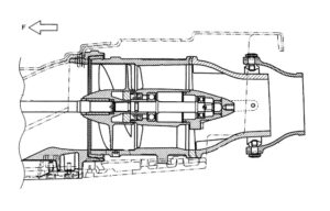
Deep well jet pump diagram

A deep water jet pump is used in deep wells. The diagram of deep well jet pump is given in the section below-

Image Credits: Diy.Stackexchange.com

How does a deep well jet pump work?

The working of a deep well jet pump is similar to a normal jet pump. In the section below we shall study about the working of a deep well jet pump.

In a deep well pump, the pipe which is connected to the impeller casing draws water inside the jet’s body that is located around 10-20 ft deep below the minimum well water level. A second pipe connects to the output of the pump. The centrifugal pump is an assembly of electric motor and impeller, when the motor starts moving the impeller connected to it also starts moving, creating a suction. Later when the fluid passes through venturi more pressure difference is created and the velocity of the fluid is increased.

Types of jet pump

There are two main types of jet pumps. The classification is done on the basis of depth of water that the pumps can draw. For shallow depths we have a different jet pump and for deep water we can use deep water jet pump.

We shall discuss about them in detail. They are given in the list below-

  1.  Shallow water jet pump- The name itself suggests that these pumps are used for shallow depths. They can work up to depth of 25 ft. The main idea behind a shallow water jet pump is that they have smaller impeller casings.
  2. Deep water jet pump– Deep water means that the depth of water is more than usual. The depths up to which deep water jet pump can work ranges from 25 ft to 110 ft.

Can you use a jet pump without using a pressure tank?

High pressure jets are used in jet pumps to displace the fluids from one place to another. While in almost every case, a jet pump uses pressure tank that provides high pressure to the stream.

The velocity of fluid is increased with the help of high pressure. The fluid is displaced using the pressure difference created inside the jet pump. However, we can use a jet pump without the help of a pressure tank. But it would cause wearing of the pump due to the pressure generated. So it is recommended to use a pressure tank in a jet pump. 

How far can a jet pump pull water?

We have studied about the different types of jet pumps and the depths at which they can be used. Theoretically, at ground levels the jet pump can pull water upto an average depth of 30 feet.

Near vacuum conditions can provide a lifting capacity upto 35 feet. The mentioned numbers are strictly for a shallow water jet pump. In real cases, due to many major losses, the number comes down to 25 feet! Mechanical losses and hydraulic losses contribute to reduction in this number.

Jet pump advantages and disadvantages

We have discussed in detail about the working of jet pump and its types. Now we shall discuss about the different advantages and disadvantages of using a jet pump.

The advantages and disadvantages of jet pump are given in the section given below-

Advantages

  • It has a great capability to provide high productivity.
  • Due to less mechanical parts in a jet pump, the chances of wear and tear are less.
  • The service life is very long.
  • The maintenance of this pump does not require much efforts and incurs less costs.
  • If we want to increase or decrease the productivity then with the help of a single injector we can achieve it.
  • The jet pump can run for longer durations without needing any assistance from us.
  • The jet pump has a very high tolerance against the abrasives present inside the fluid.

Disadvantages

  • Other artificial lifts are more efficient than jet pumps.
  • Space limitation is a major concern while using jet pumps.
  • Presence of very high pressure surface lines.
  • Very high power is consumed by jet pumps.

How does a jet pump work on a return fuel system?

Return fuel system is used in internal combustion engines, it comes with a hose that is connected with a carburettor. Sometimes excess fuel is left after a complete combustion cycle, this excess fuel is sucked in by the return fuel system.

Fuel is under high pressure inside the engine cylinder, due to the high pressure a suction is created due to the venturi action inside the pump. As a result of this, excess fuel is drawn towards the fuel tank. The fuel flows through auxilliary pipe system present inside the cylinder.

How does a two line jet pump work?

The name of this jet pump suggests that it uses two pipes. Larger pipe is used for upstream and smaller pipe for downstream.

The two line jet pumps are assisted by venturi that is situated at the bottom of pipes. Water is pumped upward using this venturi. Two line jet pumps can be used in wells, a lake or sometimes even in a water tank.

How does a convertible jet pump work?

This type of pump is versatile in nature. It is mainly used in applications like pumping water from lakes, wells or sprinkler systems.

The same principle that is used in jet engines is used in convertible jet pumps. In convertible jet pumps also, we use nozzle and venturi to pump the water. The internal components of a convertible jet pump is made up of thermo plastics and some times iron too. Since thermo plastics are weaker than iron, the iron parts are long lasting than those made up of thermo plastics.

How does a jet pump work for a jet ski?

We all can refer to jet ski as a water bike. It resembles a bike with the only difference that it runs on water. Jet ski can achieve high speeds, these speeds are achieved with the help of a jet pump.

The jet ski uses the third law of motion to move forward. When we apply the throttle, a centrifugal pump inside the jet ski starts moving as a result of which water is sucked in. The water is taken from the water body itself. The water passes through a nozzle and exits with a very high velocity. Due to high exit velocity the water pushes the jet ski in the forward direction.

The Ultimate Guide to Finding Sliding Friction: A Comprehensive Approach

how to find sliding friction

Sliding friction, also known as kinetic friction, is a crucial concept in physics that describes the force that opposes the relative motion between two surfaces in contact. Understanding how to accurately determine sliding friction is essential for various applications, from engineering design to everyday problem-solving. In this comprehensive guide, we will delve into the intricacies of calculating sliding friction, providing you with the necessary tools and techniques to master this fundamental topic.

Understanding the Basics of Sliding Friction

Sliding friction is the force that acts on an object as it slides across a surface. This force is proportional to the normal force, which is the force exerted by the surface on the object perpendicular to the surface. The relationship between sliding friction, normal force, and the coefficient of kinetic friction is expressed by the formula:

fk = μk × N

Where:
fk is the kinetic (sliding) friction force
μk is the coefficient of kinetic friction
N is the normal force

The coefficient of kinetic friction, μk, is a dimensionless quantity that depends on the materials in contact and the surface conditions. It is typically less than the coefficient of static friction, μs, which is the friction force that must be overcome to initiate motion.

Calculating the Normal Force

how to find sliding friction

The normal force, N, is the force exerted by the surface on the object perpendicular to the surface. For an object resting on a flat surface, the normal force is equal to the object’s weight, which can be calculated as:

N = m × g

Where:
m is the mass of the object
g is the acceleration due to gravity (9.8 m/s² on Earth)

For example, if an object has a mass of 10 kg and is resting on a flat surface, the normal force would be:

N = 10 kg × 9.8 m/s² = 98 N

Determining the Coefficient of Kinetic Friction

The coefficient of kinetic friction, μk, is a crucial parameter in the calculation of sliding friction. This value depends on the materials in contact and the surface conditions, and it must be determined experimentally or obtained from reference tables.

Here are some typical values of the coefficient of kinetic friction for common material combinations:

Material Combination Coefficient of Kinetic Friction (μk)
Steel on steel 0.10 – 0.15
Aluminum on steel 0.45 – 0.61
Rubber on concrete 0.50 – 0.80
Wood on wood 0.20 – 0.50
Teflon on Teflon 0.04 – 0.10

It’s important to note that the coefficient of kinetic friction can vary depending on factors such as surface roughness, temperature, and the presence of lubricants or contaminants.

Calculating Sliding Friction Force

Once you have determined the normal force and the coefficient of kinetic friction, you can calculate the sliding friction force using the formula:

fk = μk × N

For example, if an object with a mass of 10 kg is resting on a surface with a coefficient of kinetic friction of 0.2, the sliding friction force would be:

fk = 0.2 × (10 kg × 9.8 m/s²) = 19.6 N

Calculating Acceleration with Sliding Friction

When an external force, Fa, is applied to an object on a surface with sliding friction, the total force on the object is the difference between the applied force and the sliding friction force:

F = Fa - fk

Rearranging the equation, we can find the acceleration of the object:

a = (Fa - fk) / m

Where:
a is the acceleration of the object
Fa is the applied force
fk is the sliding friction force
m is the mass of the object

For example, if an object with a mass of 5 kg is subjected to an applied force of 20 N and the sliding friction force is 10 N, the acceleration of the object would be:

a = (20 N - 10 N) / 5 kg = 2 m/s²

Practical Applications and Examples

Sliding friction is a fundamental concept in physics with numerous practical applications. Here are a few examples:

  1. Braking Systems: Understanding sliding friction is crucial in the design of braking systems for vehicles. The coefficient of kinetic friction between the brake pads and the brake discs or drums determines the braking force and the vehicle’s stopping distance.

  2. Mechanical Devices: Sliding friction plays a crucial role in the design and operation of various mechanical devices, such as bearings, gears, and pulleys. Accurate calculation of sliding friction is necessary to ensure efficient and reliable performance.

  3. Inclined Planes: When an object is placed on an inclined plane, the sliding friction force acts parallel to the surface, opposing the motion of the object. Analyzing the sliding friction force is essential in determining the object’s acceleration or the minimum angle required for the object to start sliding.

  4. Robotics and Automation: In the field of robotics and automation, understanding and controlling sliding friction is crucial for the precise movement and manipulation of objects by robotic systems.

  5. Sports and Recreation: Sliding friction is an important factor in various sports and recreational activities, such as skiing, snowboarding, and ice skating. Analyzing the sliding friction can help athletes and designers optimize equipment and techniques for improved performance.

Conclusion

Mastering the concept of sliding friction is a crucial step in understanding and applying physics principles in various real-world scenarios. By following the comprehensive approach outlined in this guide, you can confidently calculate sliding friction, determine the normal force, and analyze the effects of sliding friction on the motion of objects. This knowledge will empower you to tackle a wide range of physics problems and design more efficient and reliable systems.

References

  1. Serway, R. A., & Jewett, J. W. (2018). Physics for Scientists and Engineers with Modern Physics (10th ed.). Cengage Learning.
  2. Halliday, D., Resnick, R., & Walker, J. (2013). Fundamentals of Physics (10th ed.). Wiley.
  3. Hibbeler, R. C. (2018). Engineering Mechanics: Statics (14th ed.). Pearson.
  4. Giancoli, D. C. (2014). Physics for Scientists and Engineers with Modern Physics (4th ed.). Pearson.
  5. Tipler, P. A., & Mosca, G. (2008). Physics for Scientists and Engineers (6th ed.). W. H. Freeman.

How Does A Jet Pump Work: Different Type Of Jet Pump And Facts

This article talks about how does a jet pump work. Pumps are normally used for sucking water from one place and transferring it to other place when the movement of water does not take place on its own.

There are many types of pumps which are used according to the requirements of the application. We cannot simply use any pump wherever we want to use. This article focuses only on the jet pump. We shall study what a jet pump is and how does it work and in what all applications the jet pump is used.

What is a pump?

A mechanical device that transfers the fluid from one place to another by utilising power in the form of electricity.

A pump is needed where the fluid won’t go itself, it will need an external source to take it from one place to another. This usually happens when the fluid moves from a lower potential to higher potential. Just like a ball cannot go up on its own and but it can come down on its own, the fluid also cannot go up on its own. It will need pump to get to the top.

What is a jet pump?

From many types of pumps present in the industry, we will study about the jet pump. The term jet suggests that it has a nozzle or small convergent area that will increase the velocity of the fluid.

The fluid velocity increases as a result of increasing pressure at the convergent area. The jet pump uses a centrifugal pump and injector. A high impulse stream is produced by the jet pump. In further sections we shall study about the different applications of jet pump and the simple working of jet pump.

How does a jet pump work ?

The main working prinicple of a jet pump is the venturi effect. The jet pump starts off as a conventional centrifugal pump.

The air inside the assembly is spilled out as soon as the pump starts, due to this a low pressure is created and hence the fluid is lifted up. The fluid right before entering the pump, passes through a venturi which increases the velocity of the fluid. Due to this a pressure difference is created again. This way the movement of water becomes more aggressive. This is how the jet pump works.

Jet pump working diagram

We have already discussed what a jet pump is and also discussed about its working. Now let us discuss about the working diagram of a jet pump.

In this section we will see the wroking diagram of a jet pump. The diagram below shows neat diagram of a jet pump.

How does a jet pump work
Image: Jet pump in a jet ski

Image credits: Wikipedia

How does a jet pump work for an oil well?

The jet pump is located at the bottom of an oil well. The jet pump is modified for the production of oil and gas production for making their production easier.

The main contents of a jet pump used in oil wells are- a diffuser, throat and nozzle. The main working fluid is pumped through the nozzle. This creates suction for the produced fluids. Now there are two fluids in the system- Suction fluids and produced fluids. These fluids are mixed inside the throat and the resulting mixture then passes through the diffuser.

How does a jet pump work for a jet ski?

Jet skis are used in water sports. They can be referred to as bikes running on water. They can achieve high speeds and this high speed can be achieved using a jet pump.

The jet ski moves forward using the third law of motion. As the throttle is applied, the pump starts moving and starts sucking water from the water body. The jet pump ejects the water with a high force. Due to third law of motion, an equal force is exerted on the jet ski, this opposite force is used to move forward.

How does a jet pump work on a return fuel system?

A return fuel system comes with a hose connected with a carburettor. The sole puprose of a return fuel system is that it sucks down the excess fuel sent in the system.

We all know that the fuel is at high pressure, this high pressure fuel creates a suction or venturi action inside the jet pump. This venturi action causes the excess fuel to be drawn out towards the fuel tank. The fuel is transported between the fuel tanks through the auxilliary pipe systems.

How does a two line jet pump work?

As the name suggests a two line jet pump uses two pipes, a larger pipe for upstream and a smaller pipe for downstream.

Two line jet pumps take the help of venturi that is situated at the bottom of the pipes. Through this venturi water is pumped upward. These can be used in wells, a lake or even a water tank.

How does a convertible jet pump work?

A convertible jet pump is a versatile pump mainly used for applications like pumping water from lakes, wells or sprinkler systems.

The principle used in jet engines is used in convertible jet pumps. In convertible jet pumps also, a nozzle and a venturi is used to pump the water. The convertible jet pumps have internal components made of thermo plastics and some times iron too. Since iron is stronger it is long lasting than the ones made of thermo plastics.

Types of jet pump

The jet pump is classified on the basis of depths that the pump can work in. Different types of jet pumps are designed for different types of depths. Below section tells us about the classification of jet pump in brief.

  1. Shallow water jet pump– As the name suggests, this type of jet pump is used to draw water of shallow depths. That is this jet pump can draw water out of a water column which is 25 feet deep.
  2. Deep water jet pump– The depth upto which a deep water jet pump can work on is between 25 feet to 110 feet. As the name suggests a deep water jet pump is used to draw water out of deep water columns.

Can you use a jet pump without using a pressure tank?

Jet pump works on the principle of high pressure jets that are used displace the water or any other fluid from one place to another. This high pressure is provided by pressure tanks some times. But these pumps do not necessarily need pressure tanks.

This pressure makes the flow of stream faster and displaces the targetted fluid. Although, a jet pump can work without a pressure tank also. This can be done in expense to wearing of the pump. Hence it is desirable to have a pressure tank in a jet pump.

What is a turbine pump?

A centrifugal pump that is installed underwater and is connected to an electric motor via shaft is known as a turbine pump. Its basic function is to pressurise the fluid and send it to the desired location to serve its purpose.

The efficiency of these pumps are very high and they are mainly used for large pumping applications. The pump works with various stages, analogous to a train being pulled by multiple engines because the load of train is so much that a single engine cannot drive. Turbo pumps are usually used inside rockets to pressurise the rocket fuel and oxidizer.

Gravity and Angular Momentum: A Comprehensive Guide for Physics Students

gravity and angular momentum

Gravity and angular momentum are two fundamental concepts in physics that are closely intertwined. Gravity is the force that attracts objects towards each other, while angular momentum is a measure of an object’s rotational motion in space-time. Understanding the intricate relationship between these two principles is crucial for a deep comprehension of various physical phenomena, from the dynamics of celestial bodies to the behavior of subatomic particles.

Gravity: Quantifying the Attractive Force

Gravity is a universal force that governs the motion of objects in the universe. The strength of the gravitational force between two objects is determined by their masses and the distance between them, as described by Newton’s law of universal gravitation:

F = G * (m1 * m2) / r^2

Where:
– F is the gravitational force
– G is the gravitational constant (6.674 × 10^-11 N⋅m^2/kg^2)
– m1 and m2 are the masses of the two objects
– r is the distance between the objects

This formula allows us to quantify the gravitational force between any two objects, provided we know their masses and the distance separating them. It is important to note that gravity is an inverse-square law, meaning that the gravitational force decreases rapidly as the distance between the objects increases.

Experimental Measurements of Gravity

Measuring the gravitational force between two objects, especially at the atomic or molecular scale, is a challenging task due to the extremely small magnitudes involved. However, researchers have developed sophisticated techniques to measure gravity at these scales.

One notable experiment was conducted by the Eöt-Wash group at the University of Washington, where they used a torsion balance to measure the gravitational force between two tungsten masses, each weighing approximately 10 kilograms. The experiment was able to measure the gravitational force with an accuracy of 1 part in 10^11, providing a precise determination of the gravitational constant, G.

In addition to these direct measurements, gravity has also been indirectly observed through its effects on the motion of celestial bodies, the bending of light by massive objects (gravitational lensing), and the detection of gravitational waves.

Angular Momentum: Quantifying Rotational Motion

gravity and angular momentum

Angular momentum is a vector quantity that describes the rotational motion of an object around a specific axis. It is defined as the product of the object’s moment of inertia (I) and its angular velocity (ω):

L = I * ω

Where:
– L is the angular momentum
– I is the moment of inertia, which depends on the object’s mass distribution
– ω is the angular velocity of the object

The conservation of angular momentum is a fundamental principle in physics, stating that the total angular momentum of a closed system remains constant unless an external torque is applied. This principle has important implications in various fields, from the dynamics of rotating machinery to the behavior of celestial bodies.

Measuring Angular Momentum

Measuring the angular momentum of an object can be done using a variety of techniques, depending on the specific system and the desired level of precision. Some common methods include:

  1. Rotational Dynamics Experiments: By measuring the torque applied to an object and its resulting angular acceleration, the angular momentum can be calculated using the formula L = I * α, where α is the angular acceleration.

  2. Optical Techniques: Laser interferometry and other optical methods can be used to precisely measure the angular velocity of an object, which can then be used to calculate its angular momentum.

  3. Spectroscopic Measurements: The angular momentum of atoms and molecules can be determined by analyzing their spectroscopic signatures, which are influenced by the object’s rotational state.

  4. Neutron Scattering: The angular momentum of subatomic particles, such as neutrons, can be measured by studying their scattering patterns when interacting with other particles or materials.

These experimental techniques have been instrumental in advancing our understanding of angular momentum and its role in various physical phenomena.

Gravity and Angular Momentum in Astrophysics

The interplay between gravity and angular momentum is particularly evident in the study of astrophysical objects, such as black holes, neutron stars, and binary systems.

Gravitational Waves and Angular Momentum

Gravitational waves are ripples in the fabric of space-time, produced by the acceleration of massive objects. These waves carry away energy and angular momentum from the system, causing it to lose stability and eventually merge.

The Laser Interferometer Gravitational-Wave Observatory (LIGO) and other gravitational wave detectors have been able to measure the gravitational waves produced by the merger of black holes and neutron stars. By analyzing the waveform of these signals, researchers can extract valuable information about the properties of the objects, including their masses, spins, and orbital angular momentum.

Black Holes and Angular Momentum

Black holes are some of the most extreme objects in the universe, and their behavior is heavily influenced by their angular momentum. The spin of a black hole is directly related to its angular momentum, and this property can have significant implications for the dynamics of matter and energy around the black hole.

For example, the spin of a black hole can affect the accretion of matter onto the black hole, the formation of jets, and the emission of radiation. Understanding the angular momentum of black holes is crucial for understanding their overall behavior and the processes that occur in their vicinity.

Binary Systems and Angular Momentum

Binary systems, consisting of two orbiting celestial bodies, are another example of the importance of angular momentum in astrophysics. The orbital angular momentum of a binary system plays a crucial role in its stability and evolution.

As the binary system loses energy and angular momentum, for example, through the emission of gravitational waves, the two objects can eventually merge, leading to the formation of a single, more massive object. The study of binary systems and their angular momentum has provided valuable insights into the formation and evolution of various astrophysical objects, including black holes and neutron stars.

Numerical Examples and Problems

To further illustrate the concepts of gravity and angular momentum, let’s consider some numerical examples and problems:

Example 1: Gravitational Force between Two Masses

Suppose two masses, m1 = 10 kg and m2 = 5 kg, are separated by a distance of 1 meter. Calculate the gravitational force between them.

Given:
– m1 = 10 kg
– m2 = 5 kg
– r = 1 m

Using the formula for gravitational force:
F = G * (m1 * m2) / r^2
F = (6.674 × 10^-11 N⋅m^2/kg^2) * (10 kg * 5 kg) / (1 m)^2
F = 3.337 × 10^-9 N

Problem 1: Calculating Angular Momentum

A solid sphere with a mass of 2 kg and a radius of 0.5 m is rotating at an angular velocity of 10 rad/s. Calculate the angular momentum of the sphere.

Given:
– m = 2 kg
– r = 0.5 m
– ω = 10 rad/s

To calculate the angular momentum, we need to find the moment of inertia of the sphere first:
I = (2/5) * m * r^2
I = (2/5) * 2 kg * (0.5 m)^2
I = 0.25 kg⋅m^2

Now, we can calculate the angular momentum:
L = I * ω
L = 0.25 kg⋅m^2 * 10 rad/s
L = 2.5 kg⋅m^2/s

Example 2: Gravitational Waves and Angular Momentum

Consider a binary system consisting of two black holes, each with a mass of 30 solar masses (M_sun = 1.989 × 10^30 kg). The black holes are separated by a distance of 100 km and are orbiting each other at an angular velocity of 1 rad/s.

Calculate the total angular momentum of the binary system.

Given:
– m1 = m2 = 30 M_sun = 30 * 1.989 × 10^30 kg = 5.967 × 10^31 kg
– r = 100 km = 1 × 10^5 m
– ω = 1 rad/s

To calculate the total angular momentum, we need to find the moment of inertia of the binary system first:
I = m1 * r^2 + m2 * r^2
I = (5.967 × 10^31 kg) * (1 × 10^5 m)^2 + (5.967 × 10^31 kg) * (1 × 10^5 m)^2
I = 5.967 × 10^39 kg⋅m^2

Now, we can calculate the total angular momentum:
L = I * ω
L = 5.967 × 10^39 kg⋅m^2 * 1 rad/s
L = 5.967 × 10^39 kg⋅m^2/s

This large value of angular momentum is typical for binary systems involving massive objects like black holes, and it plays a crucial role in the dynamics and evolution of these systems, including the emission of gravitational waves.

Conclusion

Gravity and angular momentum are fundamental concepts in physics that are deeply interconnected. Understanding the quantifiable aspects of these principles, including the formulas, experimental measurements, and their applications in astrophysics, is essential for a comprehensive understanding of the physical world.

By exploring the numerical examples and problems presented in this guide, physics students can develop a stronger grasp of the practical applications of gravity and angular momentum, and how these concepts shape the behavior of various physical systems, from the microscopic to the cosmic scale.

References

  1. Quizlet – Phy Flashcards: https://quizlet.com/589600152/phy-flash-cards/
  2. Physics Stack Exchange – Has gravity ever been experimentally measured between two atoms?: https://physics.stackexchange.com/questions/130594/has-gravity-ever-been-experimentally-measured-between-two-atoms
  3. Quanta Magazine – Mass and Angular Momentum, Left Ambiguous by Einstein, Get Defined: https://www.quantamagazine.org/mass-and-angular-momentum-left-ambiguous-by-einstein-get-defined-20220713/
  4. Springer – Gravitational waves with orbital angular momentum: https://link.springer.com/article/10.1140/epjc/s10052-020-7881-2

The Ratio of Rotational and Translational Kinetic Energy of a Sphere

the ratio of rotational and translational kinetic energy of a sphere

Summary

The ratio of rotational to translational kinetic energy for a sphere depends on the sphere’s moment of inertia and its velocity. For a solid sphere, the ratio is 1/5, while for a hollow sphere, the ratio is 1/3. This article provides a detailed technical specification of the ratio, including the relevant formulas, derivations, and examples.

Moment of Inertia of a Sphere

the ratio of rotational and translational kinetic energy of a sphere

The moment of inertia of a sphere is a measure of its resistance to rotational acceleration. For a solid sphere of mass m and radius r, the moment of inertia is given by:

I = (2/5)mr^2

For a hollow sphere of mass m and radius r, the moment of inertia is given by:

I = (2/3)mr^2

Kinetic Energy of a Sphere

The total kinetic energy of a sphere is the sum of its translational kinetic energy and its rotational kinetic energy.

The translational kinetic energy is given by:

KE_translational = (1/2)mv^2

where v is the velocity of the sphere’s center of mass.

The rotational kinetic energy is given by:

KE_rotational = (1/2)I*ω^2

where ω is the angular velocity of the sphere.

Relationship between Linear and Angular Velocity

For a sphere rolling without slipping, the linear velocity v of the center of mass is related to the angular velocity ω by:

v = r*ω

where r is the radius of the sphere.

Ratio of Rotational to Translational Kinetic Energy

Substituting the expressions for moment of inertia, translational kinetic energy, and rotational kinetic energy, we can derive the ratio of rotational to translational kinetic energy for a sphere.

For a solid sphere:

(KE_rotational)/(KE_translational) = [(1/2)(2/5)mr^2*ω^2]/[(1/2)mv^2] = (1/5)(r*ω/v)^2 = (1/5)

For a hollow sphere:

(KE_rotational)/(KE_translational) = [(1/2)(2/3)mr^2*ω^2]/[(1/2)mv^2] = (1/3)(r*ω/v)^2 = (1/3)

Therefore, the ratio of rotational to translational kinetic energy for a sphere depends on whether the sphere is solid or hollow:

  • For a solid sphere, the ratio is 1/5.
  • For a hollow sphere, the ratio is 1/3.

Examples and Numerical Problems

Example 1: A solid sphere of mass 2 kg and radius 0.1 m is rolling without slipping at a linear velocity of 5 m/s. Calculate the ratio of its rotational to translational kinetic energy.

Given:
– Mass, m = 2 kg
– Radius, r = 0.1 m
– Linear velocity, v = 5 m/s

Using the formula for a solid sphere:
(KE_rotational)/(KE_translational) = (1/5)(r*ω/v)^2

Since v = r*ω, we can substitute:
(KE_rotational)/(KE_translational) = (1/5)

Therefore, the ratio of rotational to translational kinetic energy for the solid sphere is 1/5.

Example 2: A hollow sphere of mass 3 kg and radius 0.2 m is rolling without slipping at a linear velocity of 8 m/s. Calculate the ratio of its rotational to translational kinetic energy.

Given:
– Mass, m = 3 kg
– Radius, r = 0.2 m
– Linear velocity, v = 8 m/s

Using the formula for a hollow sphere:
(KE_rotational)/(KE_translational) = (1/3)(r*ω/v)^2

Since v = r*ω, we can substitute:
(KE_rotational)/(KE_translational) = (1/3)

Therefore, the ratio of rotational to translational kinetic energy for the hollow sphere is 1/3.

Conclusion

In summary, the ratio of rotational to translational kinetic energy for a sphere depends on the sphere’s moment of inertia, which in turn depends on whether the sphere is solid or hollow. For a solid sphere, the ratio is 1/5, while for a hollow sphere, the ratio is 1/3. This relationship is derived from the formulas for moment of inertia, translational kinetic energy, and rotational kinetic energy, and is an important concept in the study of rotational dynamics.

References

  1. OpenStax, College Physics for AP® Courses, OpenStax, Houston, TX, 2018, pp. 282-285.
  2. HyperPhysics, “Rotational Kinetic Energy,” Georgia State University, accessed June 25, 2024, https://hyperphysics.phy-astr.gsu.edu/hbase/rotq.html.
  3. Khan Academy, “Rotational motion: work and energy,” accessed June 25, 2024, https://www.khanacademy.org/science/physics/torque-and-angular-momentum/rotational-work-and-energy/a/rotational-motion-work-and-energy.

How to Find Angular Momentum with Mass: A Comprehensive Guide

how to find angular momentum with mass

Angular momentum is a fundamental concept in classical mechanics that describes the rotational motion of an object around a fixed axis. It is a crucial quantity in understanding the dynamics of rotating systems, from the motion of planets to the spin of a basketball. In this comprehensive guide, we will delve into the details of how to calculate angular momentum with mass, providing you with a thorough understanding of the underlying principles and practical applications.

Understanding Angular Momentum

Angular momentum, denoted as L, is a vector quantity that represents the product of an object’s moment of inertia (I) and its angular velocity (ω). The formula for angular momentum is:

L = I × ω

Where:
– L is the angular momentum (in kg·m²/s)
– I is the moment of inertia (in kg·m²)
– ω is the angular velocity (in rad/s)

The moment of inertia (I) is a measure of an object’s resistance to changes in its rotational motion. It depends on the distribution of the object’s mass around the axis of rotation. For a point mass, the moment of inertia is given by:

I = m × r²

Where:
– m is the mass of the object (in kg)
– r is the distance from the axis of rotation (in m)

The angular velocity (ω) is a measure of how fast an object is rotating around a fixed axis. It is given by the formula:

ω = v / r

Where:
– v is the linear velocity of the object (in m/s)
– r is the radius of the circular path (in m)

Calculating Angular Momentum for a Point Mass

how to find angular momentum with mass

To find the angular momentum of a point mass, we can use the formula:

L = m × v × r

Where:
– L is the angular momentum (in kg·m²/s)
– m is the mass of the object (in kg)
– v is the linear velocity of the object (in m/s)
– r is the distance from the axis of rotation (in m)

Let’s consider an example:

Suppose we have a point mass with a mass of 2 kg, a linear velocity of 5 m/s, and a distance from the axis of rotation of 3 m. We can calculate the angular momentum as follows:

L = m × v × r
L = 2 kg × 5 m/s × 3 m
L = 30 kg·m²/s

This formula can be used to calculate the angular momentum of a single point mass. However, in many real-world situations, we need to consider the angular momentum of a system of particles or a rigid body.

Angular Momentum of a System of Particles

To find the angular momentum of a system of particles, we need to sum the angular momenta of all the individual particles. The formula for the total angular momentum of a system of n particles is:

L_total = Σ (m_i × v_i × r_i)

Where:
– L_total is the total angular momentum of the system (in kg·m²/s)
– m_i is the mass of the i-th particle (in kg)
– v_i is the linear velocity of the i-th particle (in m/s)
– r_i is the distance from the axis of rotation to the i-th particle (in m)

For example, consider a system of three particles with the following properties:

Particle Mass (kg) Linear Velocity (m/s) Distance from Axis (m)
1 2 5 3
2 3 4 2
3 1 6 4

To find the total angular momentum of the system, we can use the formula:

L_total = (2 kg × 5 m/s × 3 m) + (3 kg × 4 m/s × 2 m) + (1 kg × 6 m/s × 4 m)
L_total = 30 kg·m²/s + 24 kg·m²/s + 24 kg·m²/s
L_total = 78 kg·m²/s

Angular Momentum of a Rigid Body

For a rigid body, the angular momentum can be calculated using the formula:

L = I × ω

Where:
– L is the angular momentum of the rigid body (in kg·m²/s)
– I is the moment of inertia of the rigid body (in kg·m²)
– ω is the angular velocity of the rigid body (in rad/s)

The moment of inertia (I) of a rigid body depends on the distribution of its mass around the axis of rotation. For common shapes, the moment of inertia can be calculated using the following formulas:

  • Solid sphere: I = (2/5) × m × r²
  • Hollow sphere: I = (2/3) × m × r²
  • Solid cylinder: I = (1/2) × m × r²
  • Hollow cylinder: I = (1/2) × m × (r₁² + r₂²)
  • Thin rod: I = (1/12) × m × L²

Where:
– m is the mass of the rigid body (in kg)
– r is the radius of the rigid body (in m)
– L is the length of the rigid body (in m)
– r₁ and r₂ are the inner and outer radii of the hollow cylinder (in m)

Let’s consider an example of a solid sphere with a mass of 5 kg and a radius of 0.5 m, rotating at an angular velocity of 2 rad/s. We can calculate its angular momentum as follows:

I = (2/5) × 5 kg × (0.5 m)²
I = 0.25 kg·m²

L = I × ω
L = 0.25 kg·m² × 2 rad/s
L = 0.5 kg·m²/s

Advanced Techniques and Applications

In addition to the basic formulas and examples provided, there are several advanced techniques and applications of angular momentum that you may encounter in more complex physics problems:

  1. Conservation of Angular Momentum: The principle of conservation of angular momentum states that the total angular momentum of an isolated system remains constant unless an external torque acts on the system. This principle has numerous applications in fields like astronomy, robotics, and sports.

  2. Angular Momentum in Quantum Mechanics: In quantum mechanics, angular momentum is a fundamental quantity that describes the rotational motion of subatomic particles. The quantization of angular momentum is a crucial aspect of quantum theory.

  3. Angular Momentum in Rotational Dynamics: Angular momentum plays a central role in the analysis of rotational dynamics, such as the motion of gyroscopes, the precession of a spinning top, and the stability of rotating systems.

  4. Angular Momentum in Orbital Mechanics: In the study of orbital mechanics, angular momentum is used to describe the motion of planets, satellites, and other celestial bodies around a central body, such as the Sun or a planet.

  5. Angular Momentum in Biomechanics: In the field of biomechanics, the analysis of angular momentum is essential for understanding the dynamics of human movement, such as the motion of limbs during sports activities or the stability of the human body during various tasks.

These advanced topics and applications of angular momentum require a deeper understanding of the underlying principles and the ability to apply them in more complex scenarios. As you continue your studies in physics, you may encounter these concepts and be able to build upon the foundation laid in this comprehensive guide.

Conclusion

In this comprehensive guide, we have explored the fundamental concepts of angular momentum and how to calculate it with mass. We have covered the formulas for finding angular momentum of a point mass, a system of particles, and a rigid body, along with relevant examples and numerical problems. Additionally, we have touched upon some advanced techniques and applications of angular momentum in various fields of physics.

By mastering the concepts presented in this guide, you will be well-equipped to tackle a wide range of physics problems involving rotational motion and angular momentum. Remember to practice regularly, apply the principles to different scenarios, and continuously expand your knowledge to become a true expert in this fascinating area of classical mechanics.

References

  1. Physics LibreTexts: Angular Momentum In Two Dimensions
  2. Dummies: How to Calculate Angular Momentum
  3. Khan Academy: Angular Momentum (video)
  4. YouTube: How to Calculate Moment of Inertia & Angular Momentum in Human Movement
  5. Hyperphysics: Angular Momentum
  6. MIT OpenCourseWare: Rotational Dynamics and Angular Momentum
  7. University of Cambridge: Angular Momentum