VBScript String Functions – An Excellent Guide for VBScript Tutorial 5

vbscript replace 300x118 1

VBScript Tutorial – Table of Content

VBScript Tutorial #1: Overview of VBScript Variables 

VBScript Tutorial #2: VBScript Conditional Statements and Loops

VBScript Tutorial #3: VBScript Procedures

VBScript Tutorial #4: VBScript Error Handling and Execute VBScript

VBScript Tutorial #5: VBScript String Functions

VBScript Tutorial #6: VBScript Date Functions

VBScript Tutorial #7: VBScript Time Functions

VBScript Tutorial #8: VBScript Array Functions

In this VBScript Tutorial, we are going to learn about the most important and frequently used VBScript String Functions, including vbscript InStr, vbscript StrComp, vbscript Mid function, etc. All the vbscript string functions are explained with an example.

VBScript Tutorial #5: VBScript String Functions

VBScript String Functions:

While working with string in vbscript, we can use vbscript string functions to perform important string operations such as search, replace, extract, get the length, comparisons, etc. Through the “VBScript String Functions” article, we will explain the frequently used built-in VBScript string functions with examples. 

Important VBScript String Functions – Summary: 

  • vbscript SubString – This method is used to extract characters from string based on provided criteria.  
  • vbscript InStr – Find the position of a particular expression(first occurrence) within a string.         
  • vbscript Replace – Replace some part with another string.    
  • vbscript Mid – This method is used to extract characters from string based on provided criteria.
  • vbscript Concatenation – This method is used to merge two or more string expressions.
  • vbscript Left – Extract characters from the left side.
  • vbscript StrComp – Compare two strings.
  • vbscript Trim – Remove spaces from both the sides (start and end) of a string.
  • vbscript Ltrim – This method clears the spaces from the left side from a specific string.
  • vbscript Rtrim – This method clears the spaces from the right side from a specific string.
  • vbscript UCase – Covert characters to upper case.      
  • vbscript LCase – Covert characters to lower case.
  • vbscript Length – This method is use to find and the return the length for a specific string expression.     
  • vbscript Right – Extract characters from the right side.          
  • vbscript StrReverse – Reversing of a string.

Important VBScript String Functions – Explanations: 

All the important vbscript string functions are explained in this section with real live example.

vbscript InStr:

The vbscript instr function finds the position of first occurrence of a particular expression available within a string and returns the position value.

Syntax: InStr([start,]string1,string2[,compare])

Parameter Description:

Start – This parameter defines the start position of string1 from where searching or checking the first occurrence of string2 will be started. This is an optional parameter. By default, if nothing is specified, the vbscript starts with 1st position.

String 1 – This string is to be searched for the occurrence checking of another string.

String 2 – This is the string expression to search for.

Compare – This is an optional field used to define the comparison type between binary or textual. The default value is 0. The possible values are – 

  • 0 = vbBinaryCompare – Perform a binary checking
  • 1 = vbTextCompare – Perform a textual checking

Example:

In this example of the vbscript InStr function, we are going to find and print the first occurrence of a search string.

string1 = "aabbccddee"
string2 = "bb"
nPostionOfOccurance = INSTR(1,string1,string2,1)
msgbox "Position of first occurance - " & nPostionOfOccurance
vbscript instr
vbscript string functions – vbscript instr

vbscript string Replace:

The vbscript string replaces function is used to replace the specified parts of a string with another string for a predefined number of occurrences.

Syntax: Replace(mainString,findString,replacewith[,startPos[,count[,compare]]])

Parameter Description:

mainString – This is the main string that is to be updated for the replacement.

findString – This string portion will be replaced in the main string.

replaceWith – This is the replacement string.

StartPos – This parameter defines the start position of the main string from where searching will be started. This is an optional parameter. By default, if nothing is specified, the vbscript starts with 1st position. Before the start position, all the characters will be removed.

Count – This is an optional parameter that is used to define the numbers of substitutions to be done. The default value for the count parameter is -1, which defines that there is no limitation on number of substitutions to be done.

Compare – This is an optional field used to define the comparison type between binary or textual. The default value is 0. The possible values are – 

  • 0 = vbBinaryCompare – Perform a binary checking
  • 1 = vbTextCompare – Perform a textual checking

Example:

In this example of the vbscript Replace function, we are going to replace all the occurrences of a particular string with another string.

mainString  = "aa bb cc dd bb ee"
findString  = "bb"
replaceWith = "zz"
startPos = 1
updatedString = Replace(mainString,findString,replaceWith,startPos)
msgbox "String after the replacement - " & updatedString 
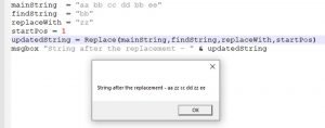
vbscript replace
vbscript string functions – vbscript replace

vbscript Mid:

The vbscript Mid function returns the specified number of characters from a string.

Syntax: Mid(string,startPos[,length])

Parameter Description:

string – The specified number of characters will be extracted from this string.

startPos – It defines the start position of the characters which is going to be extracted.

length – This is an optional field that defines the length of the extracted text. If the parameter is not provided, the vbscript mid function extract the entire string after the start position.

Example:

In this example of the vbscript Mid function, we are going to extract characters of length three from position 4.

source_string  = "aaabbbcccddd"
startPos = 4
length = 3
captured_string = Mid(source_string,startPos,length)
msgbox "Extracted string of length 3 from position 4 is  - " & captured_string
vbscript mid
vbscript string functions – vbscript mid

vbscript substring:

There is no specific method with the name substring. But just like the java substring method, we can use the vbscript Mid function. 

vbscript string concatenation:

The vbscript string concatenation operator is used to add/ concrete two or more strings. The vbscript string concatenation operator is ‘&.’

Syntax: string1 & string2 & string3 …

Example:

In this example, we will add two strings using the vbscript string concatenation operator,

string1 = “abc” & “def”

After the execution, the variable string1 is going to hold the value as “abcdef”

vbscript Left function:

The vbscript Left function extracts a specified number of characters from the left side of a string.

Syntax: Left(string,length)

Parameter Description:

string – The specified number of characters will be extracted from this string from the left side.

length – It denotes the length of the characters which will be extracted from left side.

Example:

In this example of the vbscript Left function, we are going to extract characters of length three from the left side.

source_string  = "aaabbbcccddd"
length = 3
captured_string = Left(source_string,length)
msgbox "Extracted charecters from Left side  - " & captured_string
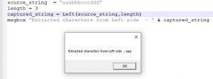
vbscript left
vbscript string functions – vbscript left

The vbscript Right function extracts a specified number of characters from the right side of a string.

Syntax: Right(string,length)

Parameter Description:

string – The specified number of characters will be extracted from this string from the right side.

length – It denotes the length of the characters which will be extracted from right side.

Example:

In this example of the vbscript Right function, we are going to extract characters of length three from the right side.

source_string  = "aaabbbcccddd"
length = 3
captured_string = Right(source_string,length)
msgbox "Extracted charecters from Right side  - " & captured_string
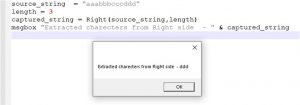
vbscript string functions - vbscript right
vbscript string functions – vbscript right

vbscript StrComp function:

The vbscript StrComp function is used to compare two strings and returns the result of the comparison. 

Syntax: StrComp(string1,string2[,compare])

Parameter Description:

string1 – One of the string expression parameter which required for the comparison. 

String2 – Another string expression parameter required for the comparison. 

Compare – This is an optional field used to define the comparison type between binary or textual. The default value is 0. The possible values are – 

  • 0 = vbBinaryCompare – Perform a binary checking
  • 1 = vbTextCompare – Perform a textual checking

The vbscript StrComp function can return one of the following values:

  • -1 (if string1 < string2)
  • 0 (if string1 = string2)
  • 1 (if string1 > string2)
  • Null (if string1 or string2 is Null)

Example:

In this example of the vbscript StrComp function, we are going to see the results for three different comparison conditions.

'Condition when string1<string2
string1 = "abcd"
string2 = "wxyz"
result1 = StrComp(string1,string2,vbTextCompare )

'Condition when string1 = string2
string1 = "abcd"
string2 = "abcd"
result2 = StrComp(string1,string2,vbTextCompare )

'Condition when string1>string2
string1 = "wxyz"
string2 = "abcd"
result3 = StrComp(string1,string2,vbTextCompare )
msgbox "Result 1: " & result1 & ", Result 2: " & result2 & " and Result 3: " & result3
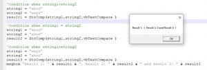
vbscript strcomp
vbscript strcomp (vbscript string functions)

vbscript Trim function:

The vbscript Trim function is used to clear all the spaces from both the side, i.e., from the beginning and end of the string.

Syntax: Trim(string)

Parameter Description:

string – It’s a string containing spaces at the left and right sides.

Example:

In this example of the vbscript Trim function, we are going to remove the spaces from both the sides of a string.

string1 = ” aaa bbb ccc ddd “

string2 = Trim(string1)

After the execution, the string2 variable will contain the value as “aaa bbb ccc ddd,” without the spaces on the left and right sides.

vbscript Ltrim function:

The vbscript LTrim function is used to remove any spaces from the left side of the string.

Syntax: Ltrim(string)

Parameter Description:

string – It’s a string containing spaces on the left side.

Example:

In this example of the vbscript LTrim function, we are going to remove the spaces from the left side of a string.

string1 = ” aaa bbb ccc ddd “

string2 = Ltrim(string1)

After the execution, the string2 variable will contain the value as “aaa bbb ccc ddd,” without the spaces from the left side.

vbscript Rtrim function:

The vbscript RTrim function is used to remove any spaces from the right side of the string.

Syntax: Rtrim(string)

Parameter Description:

string – It’s a string containing spaces on the right side.

Example:

In this example of the vbscript RTrim function, we are going to remove the spaces from the right side of a string.

string1 = ” aaa bbb ccc ddd “

string2 = Rtrim(string1)

After the execution, the string2 variable will contain the value as “ aaa bbb ccc ddd,” without the spaces from the right side.

vbscript Uppercase i.e. vbscript UCase function:

The actual function name for vbscript Uppercase is vbscript Ucase function. The vbscript UCase function is used to convert the characters of any string(irrespective of case) into upper case characters.

Syntax: UCase(string)

Parameter Description:

string – It’s a string to convert into uppercase characters.

Example:

In this example of the vbscript UCase function, we are going to convert a string containing lower and upper cases into upper case characters.

string1 = “aBcD aabb”

string2 = Trim(string1)

After the execution, the string2 variable will contain the value as “ABCD AABB.”

vbscript Lowercase i.e. vbscript LCase:

The vbscript LCase function is used to convert the characters of any string(irrespective of case) into lower case characters.

Syntax: LCase(string)

Parameter Description:

string – It’s a string to convert into lowercase characters.

Example:

In this example of the vbscript LCase function, we are going to convert a string containing lower and upper cases into lower case characters.

string1 = “aBcD aabb”

string2 = Trim(string1)

After the execution, the string2 variable will contain the value as “abcd aabb.”

vbscript length function:

The vbscript Length function is used to find the length of a particular string. It returns the length as an integer value.

Syntax: Length(string)

Parameter Description:

string – Any string expression.

Example:

In this example of the vbscript length function, we are going to find the length of any particular string expression.

string = “aBcD aabb”

strLength = Length(string)

After the execution strLength variable will contain the length of the string as 9.

vbscript StrReverse function:

The vbscript StrReverse function is used to reversing any string.

Syntax: StrReverse(string)

Parameter Description:

string – Any string expression.

Example:

In this example of the vbscript StrReverse function, we are going to reversing the characters of a particular string.

string1 = “abcde”

string2 = Length(string1)

After the execution, the string2 variable will contain the reverse string as “edcba.”

Conclusion:

Through this VBScript String Functions article, we have learned about the important VBScript String Functions, including vbscript InStr, vbscript StrComp, vbscript Mid funtions, etc. In the next vbscript tutorial, we will explain about VBScript Date and Time functions. Please click here to get more details.

Nanofluid: 17 Important Explanations

nanofluid 291x300 1

Following contents are explained in this articles:

  • Nanofluid definition | what is nanofluid?
  • What is base fluid?
  • How do you make a Nanofluid?
  • What is hybrid nanofluid?
  • Uses of nanofluid | applications of nanofluid
  • Types of nanofluid & Its Poperties

Nanofluid definition | What is nanofluid?

Nanofluid is fluid that consists of a base fluid with nanosized particles (1–100nm) suspended in it. Nano particles used in this type of studies are made of a metal or metal oxide, increase conduction and convection, allowing for more heat transfer. In the past few years, high-speed advancement in nanotechnology has made emerging of new generation coolants called nanofluid.

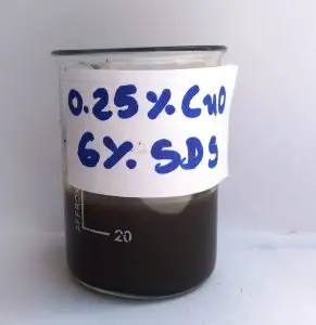
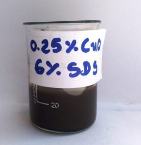
Let’s take example, check figure below. The CuO (metal oxide) nanoparticles are added to make nanofluid with a volume fraction of 0.25% CuO. The nanoparticle is dispersed in distilled water (base fluid). The surfactant sodium dodecyl sulfate (SDS) is added to the nanofluid for the stability of nanoparticles.

Figure 1. Nanofluid
CuO Nanofluid

What is base fluid?

The nanoparticles are suspended in some ordinary liquid coolant like distilled water, ethylene glycol, oil, refrigerants, etc. This widely used ordinary coolant is known as base fluid.

You might have noticed while mechanic changing or pouring coolant in your car radiator. Do you remember its color? Yes, it’s green. That green colored fluid (coolant) is ethylene glycol.

Let’s know about base fluid oil. You might have noticed mechanic changing oil from your car or bike. It is lubrication and transmission system oil. This type of oil can be base fluid for nanofluid preparation.

How do you make a Nanofluid?

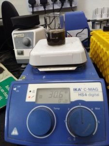
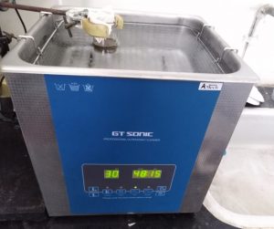
                The preparation of nanofluid can be possible by following two widely used methods. It is prepared by dispersing nanoparticles in base fluid with a magnetic stirrer and sonicator, as shown in figure “Preparation of nanofluid : Sonicator”.

                There are two types of stirrer used to disperse particles into basefluid, one is the magnetic and another is mechanical. The another lab instrument called ultrasonic sonicator is also required for proper dispersion.

preparation 1 1
Preparation of nanofluid : magnetic stirrer

preparation 2
Preparation of nanofluid : Sonicator

Two-step method

The two-step procedure is the most widely used method for preparing nanofluid. The chemical and physical peocesses are used to produce dry powder of nanoparticles.

The powder of particles is added into the base fluid. The second step could be intensive magnetic force agitation or ultrasonic agitation. The two-step procedure is the economic procedure to produce nanofluid on  bulk because the nano fluid requirements are raising with new applications.

Use of surfactant in nanofluid

The nanoparticles have large surface area and surface activity which lead to aggregate. The use of surfactant is convenient method to get good stability. However, the surfactants’ functionality under high temperatures is also a big issue, especially for high-temperature applications.

One-step method

Eastman suggested a one-step method of vapor condensation. It is used prepare Cu/ethylene glycol (EG) nanofluid to limit the agglomeration of nanoparticles.

The use of one-step preparation method avoid spreading the particles in the fluid. There are some function not needed in this method. This method eliminates drying of particles, storage of material, and spreading. Agglomeration is limited in one -step method. it also increases stability of nanofluid.

Vacuum method – SANSS

 (full form Submerged -arc -nanoparticle -synthesis- system)

It is one of the preparation method of nanofluid with good efficiency. Different dielectric fluid are used in this method

The shape of nanoparticles are like different different type. The procedure avoids the undesired particle aggregation reasonably well. There are some disadvantages of this method. There is some reactant remain present in nanofluid.

What is a hybrid nanofluid?

A hybrid material is a combination of physical and chemical properties of two or more materials. The two or more nanoparticles are dispersed in a base fluid to achieve desired properties for individual applications. The making of nanofluid with two or more similar or different nanoparticles is popular as hybrid nanofluid. The work on hybrid nanofluid is not extensively done.
There are many experimental studies on hybrid nanofluid is still left to be done. The generally used hybrid nanofluids are Al2O3/Cu, Al2O3/CNT, Cu/TiO2, CNT/Fe3O4, etc.

The hybrid nanofluid is a new research area for thermal engineering researcher to obtain enhanced cooling system.

Usage of nanofluid

                Nanofluid can be utilized for various different applications. These uses not affecting energy transfer thoroughly, they may be reduce the basic need for conventional fuel, electrical energy, or gas. Let’s read some important application of nanofluids

Electronic devices cooling

               The research going on the electronics suggests that the use of nanofluid can perform superior heat transfer. The vapour chamber is utilizing nanofluid in it for better heat transfer.

Jacket-water fluid in electricity generator

               The management of machinery space is main problem in all automobile vehicle. The size of component (cooling) can be reduced only if we improve heat transfer performance of parts. The nanofluid is the one of the option to improve performance of part and develop compactness.

Solar energy – thermal energy system

                To absorb solar radiation, the working fluid is passes through solar thermal energy system. The energy absorbed by fluid is sent to heat exchanger for other purposes.The solar energy absorbed by working fluid is generally transferred to the heat exchanger for other applications.

Cooling oil in Transformer

                The transformer is power transmission electrical equipment. The generated heat in transformer is absorbed by oil. If we add nanoparticle in cooling oil. The performance of transformer can be improved.

Other usage of nanofluid in the field of heat transfer enhancement:

Refrigeration process

                The refrigeration process is working on different thermodynamic cycles.  The working fluid in this process is refrigerant. The thermal properties of some refrigerant can be improved by use of nanoparticle.

Cooling system of nuclear energy

                The huge amount of heat is produced in the nuclear fission. It is required to arrange proper cooling to system. The nano fluid is advance fluid which can be utilized in nuclear cooling system.

Types of nanofluid

The types of nanofluid are dependent on the use of different types of nanoparticles and base fluids. There are three types of nanoparticles, like pure metal, metal oxide, and carbide-based nanoparticles. These particles are dispersed in various choices of base fluids like water, water/ethylene glycol, oil, ethylene glycol, etc.

Pure Metal Metal oxides Carbide
Al Al2O3 Diamond
Cu CuO Graphite
Fe Fe2O3, Fe3O4 Single wall nanotube
Ag Ag2O Multiwall nanotubes
Zn ZnO  
Ti TiO2  

Properties of nanofluid

Thermal conductivity is one of the vital property related to heat transfer for nanofluid. It is high thermal conductivity compared to standard cooling liquid, it is an essential characteristic for many applications. Use of copper nanoparticles with ethylene glycol results in an increase in thermal conductivity by 40% compared to the base fluid.

All processes indicates that thermal conductivity basic for proper cooling system in any devices. In the cooling system, a large surface area and high thermal conductivity are attributed to this heat transfer improvement.

The ratio of surface area and volume is main criteria for thermal conductivity improvement. This ration can be increased by using small size nanoparticles. The thermal conductivity is raised by using higher concentration of the particles.

The properties like density, viscosity, specific heat, thermal conductivity are well known for base fluid. The properties of nanofluid can be calculated theoretically by correlations suggested by various researchers. These properties also can be measured with multiple instruments experimentally in the lab.

The density of nanofluid can be calculated using correlation as  

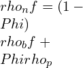
\rho_{n}f=(1-\Phi)\rho_{b}f+\Phi{\rho_{p}}

Where ρpand ρbfare the nanoparticles’ densities and base fluid, respectively, and фis the volume concentration (% w/w) of nanoparticles dispersed in the base fluid. As per the idea of the strong fluid combination, the specific heat of nanofluid is given by the accompanying:

{ C }p_{ nf }=\quad \frac { (1-\phi ){ \rho }_{ bf }\quad { Cp }_{ bf }+\phi \quad { \rho }_{ p }{ Cp }_{ p } }{ { \rho }_{ nf } }

Where cppand cpbf, are the specific heat of the nanoparticles and base fluid, respectively. The viscosity of nanofluid can be obtained from the following equation:

{\mu}_{nf}={\mu}_{bf}(1+a\phi)

Credit Einstein 1906

 a is constant in viscosity equation and its  value is 14.4150 to  calculate viscosity. This formula is basically given for Brownian motion of particle in fluid. One well-known formula for computing the thermal conductivity of nanofluid is the Kang model which is expressed in the following form :

K_{ nf }=\quad { K }_{ bf }\frac { { K }_{ p }+(n-1){ K }_{ bf }-\phi \quad (n-1)\quad ({ K }_{ bf }-{ K }_{ p }) }{ { K }_{ p }+(n-1){ K }_{ bf }+\phi\quad ({ K }_{ bf }-{ K }_{ p }) }

Credit Hamilton and Crosser (1962)

Question and Answers

What is nanofluid?

It is an advance fluid. It is prepared by dispersing nanoparticles in the base fluid.

What is base fluid?

 The base fluid is conventional coolant liquid. It is used to prepare nanofluid.

Give the examples of some commonly used nanoparticles to prepare nanofluid.

The commonly used nanoparticles are Copper (Cu), Aluminium (Al), Iron (Fe), Aluminium Oxide (Al2O3), Copper Oxide (CuO), Titanium Oxide (TiO2 ) etc.

What are widely used preparation methods of nanofluid?

There are two methods widely used mentioned as below:

  1. Two-step method
  2. One-step method

What is the stability of nanofluid?

The stability can be stated as how long the particle keep dispersed in the base fluid. Technically, The higher stable nanofluid is one who has less sedimentation.

What is the use of surfactant in preparation of nanofluid?

The surfactant is used in nanofluid to increase its stability. The commonly used surfactant is sodium dodecyl sulfate (SDS).

Why hybrid nanofluid became a new research topic?

The individual application needs the desired properties of the material. To get likely properties in nanofluid, more than one nanoparticles are added in the base fluid.

Why the use of nanofluid results enhanced heat transfer?

The nanofluid is an advanced fluid with a higher thermal conductivity as the nanosized particles provide more surface area to conduct heat transfer.

How can nanofluid reduce the size of the heat exchanger?

The convention coolant used in heat exchanger shows less heat transfer as compared to nanofluid. The use of nanofluid requires proportionally less sized heat exchanger as compared to the conventional coolant.

Conclusion

                This article is about basic introduction of nanofluid, preparation of nanofluid, application of nanofluid and properties of nanofluid. Recently, it is advance coolant in heat transfer applications. The scope of nanofluid is vast in present nanotechnology world. The nanofluid and its applications can be a good topic for students and researcher for project work.

For more details regarding it, please refer click here

More topic related to Nanofluid and heat transfer, please click here

Transmission Line: 5 Facts You Should Know

TINE

Cover Image Credit – Sajad-HasanAhmadiTV antenna connectorsCC BY-SA 4.0

Points of Discussion: Transmission Line

  • Introduction
  • Purpose of transmission line
  • Analysis of transmission line
  • Types of transmission line
  • Applications of transmission lines

Introduction to Transmission Line

A transmission line is a specially designed cable for transmission of power. It conducts only electromagnetic waves to the load at low frequencies in a guided way.

            Transmission line operates at microwave frequency domain and radio frequency domain where power is assumed as an electromagnetic wave. That is why if any cable can guide an electromagnet signal, then it will be called a Transmission line.

            The transmission line is the result of researches of James Maxwell, Lord Kelvin, and Oliver Heaviside. The fault and drawbacks of the ‘Atlantic telegraph cable’ and invention of telegrapher’s equation made the way out for the line.

Purpose of transmission line

Regular cables which transfer electrical energy are designed to conduct power at lower frequency AC. They cannot carry power in FR range or above 30 kilo hertz as the energy gets disconnected at joints and connectors, and some time does not reach the destination. This lines resolve these problems. They are constructed specially to minimize the reflections and loss of power and also uses the impedance matching to carry power.

            This lines are constructed with a uniform cross-sectional area. That is why they provide uniform impedance which is in terms known as characteristic impedance.

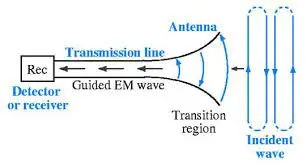
Transmission Line

Use of Transmission Line in antenna

            The wavelength of the electromagnetic waves gets shorter as the frequency gets higher of the electromagnetic waves.  Transmission lines are crucial because when the wavelength is short enough, the length of the wire contributes to the past of the wavelength.

What is a Yagi Uda Antenna? Click here for details!

Analysis of Transmission line

            We assume a four-terminal model of the transmission lines to analyze the construction and working of lines. It is equivalent to a typical two-port circuit. 

            We assume that the circuit is linear, which means that the complex voltage at any port is relational to the complex current for the reflectionless condition. Also, we assume that two of its ports are transposable.

Characteristics impedance of transmission line

Characteristic impedance or (Z0) is an essential parameter of the line. It can be defined as the ratio of the magnitude of the voltage to the magnitude of the current of a wave, travelling along a reflection less line.

Characteristics impedance controls the behaviors of the line only if the line is uniform in length. Generally, for co-axial cables, characteristic impedance has a value of fifty to seventy ohms, and for warped pair of wires, the value is 100 ohms. For untwisted pair, the value is 300 ohms.

Transmission line reflection coefficient

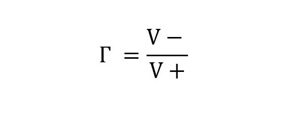
The line’s reflection coefficient is given by the ratio of the complex magnitude of the reflected signal to the incoming signal. It is represented by the Greek alphabet – Г and expressed as –

Transmission line reflection coefficient

where V+ is the complex voltage of the incoming voltage and  V- is the complex voltage of the reflected wave.

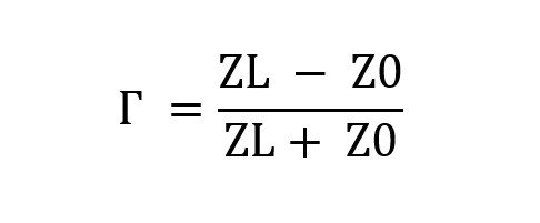
It has a relation with the load impedance and characteristic impedance. The expression is given below.

Transmission line

Here ZL is the load impedance, and Z0 is the characteristic impedance.

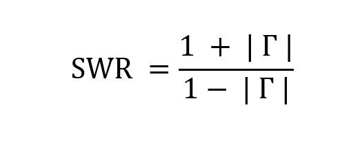
The standing wave ratio also has a relation with this line reflection coefficient. The connection is given as –

Transmission line

The relation between Standing Wave Ratio and transmission line reflection coefficient.

Matched condition of transmission line:

The aim of a transmission line is to deliver the maximum power from the source to destination load and to minimize the reflection and loss of the power. The ‘matched’ condition can fulfil this desired. If the destination’s load impedance is made same or equal to the value of the characteristic impedance of the line, then the line achieves ‘matched’ condition.

            Instead of the ‘matched’ condition, the transmission suffers some loss. Like, ohmic loss. There is also another substantial loss that occurs when this line works in high frequency ranges. The loss is known as dielectric loss. Here, the inside elements of this lines, grips the EM energy and produces heat.

            The aggregate loss of this line is measured by the unit dB/m. The losses are dependent on the frequency of the signal, as mentioned earlier. The constructor companies of this usually provide a chart of loss. It shows the loss of power at different frequencies. If any line suffers a loss of three decibel/meter, then the power received at the load will be half of the power supplied.

What is horn antenna? get an overview here!

Types of transmission lines

 These come with certain types depending upon its physical structure and according to the needs. Some of the essential and widely used types of transmission lines are listed below. Please go through it and discover them.

Co-axial cables:

It is one of the widely used forms of lines. It restricts the whole EM wave inside the cable. Thus, co-axial cables can be bent, strapped as well as twisted to an extent without affecting the operation.

Co axial cable

Cross-section of a Co-axial Cables, Image Credit: Tkgd2007Coaxial cable cutawayCC BY 3.0

EM waves promulgate in TEM or transverse electric and magnetic mode For the RF range applications. Here, both the electric and magnetic fields are perpendicular with the promulgate directions. The electric field becomes radiated, and the magnetic field becomes circumferential.

If the wavelength of the wave is shorter than the circumference of the co-axial cable, then the TEM gets divided into two. The modes are then known as TE or transverse electric and TM or transverse magnetic.

Co-axial cables have broad applications for televisions. It was primarily used for telephones in the middle of twenty century.

Microstrip transmission lines:

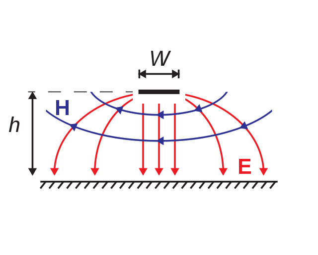
A microstrip network is basically a tiny conductive plane, placed parallelly to the ground surface. It can be designed by putting a thin and flat metallic plane on the side of a PCB. The opposite surface must be the ground plane. The characteristic impedance of the microstrip type line depends on that conductive strip. The height, width, dielectric coefficient of the conductive strip provides the characteristic impedance. A point to be remembered that the microstrip type line is an open structure while the co-axial cable is a closed one.

640px Electric and Magnetic Fields for Microstrip.svg

Electric & Magnetic field of Microstrip Transmission Line,

Image Credit: Dassault

Twisted pair transmission lines:

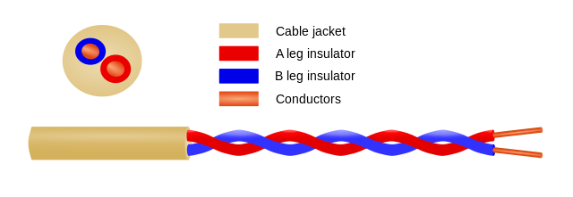
In this type of line where pairs of wire are assembled together to form a single chain or a cable is known as tangled pair transmission lines. These types of lines are used in global telephonic communications. Also, it has used in data circulation inside buildings. This type is not economical due to its properties.

640px Twisted pair.svg

Image of a Twisted Pair types. Image Credit – Spinningspark at en.wikipediaTwisted pairCC BY-SA 3.0

Star quad:

Star quad is another wire-combinational formation. It uses four cables, and all the conductors of the four cables are twisted and assembled along the axis of the cable. In this formation, each and every pairs uses a far pair to get connected.

The combinational form of twisted, balancing and quadrupole pattern of transmission lines has several benefits as it reduces noise, particularly for short signal level usage like – cables of the microphone.

Transmission line

Descriptive image of a star quad cable, Image Source – Spinningspark at en.wikipediaDM quadCC BY-SA 3.0

This type of line has applications in four-wire telephony, two-wire applications.

It also induces high capacitance which further causes distortion and losses.

Applications of transmission lines | Uses of transmission lines

Transmission lines have several benefits over regular electrical cables in specific domains. That is why it has several applications. Let us discuss some of them.

  • Electromagnetic powers are supplied in high frequency domains with minimum loss. Tv and radio cables for connecting the aerials is one of the most famous examples.
  • These are also used for the generation of pulses by charging and discharging this lines. A significant example of this type of line is – Blumlein Transmission Line. Radars have also multiple application of this kind.
  • These are also applied in stub filters. Stub filters are typically wired in a parallel connection and transfer power from the source to destinations.

Check out more on Electronics! Click Here!

Pulse Code Modulation (PCM): 7 Complete Quick Facts

PCM Sampling 300x225 1

The subject of Discussion: Pulse Code Modulation (PCM)

  • What is Pulse Code Modulation?
  • Important features of PCM
  • Sampling Method in Pulse Code Modulation (PCM)
  • Encoding in Pulse Code Modulation (PCM)
  • What is Quantization?
  • Advantages of PCM
  • Disadvantages of PCM
  • Important applications of Pulse Code Modulation (PCM)

What is Pulse Code Modulation?

Definition of PCM:

Pulse code modulation or PCM is a distinct type of A-to-D conversion method in which the data or info enclosed in the samples of an analog signal is obtainable by a digital procedures.”

In this method, each of the digital signals has n number of binary digits, there are M= 2n unique number of code is possible, and all these codes have a specific amplitude level. However, for each sample significance from the analog signal could be any one of an unlimited levels.

The digitally encrypted word characterized by the amplitude closest to the actual sampled value is used. This is named as quantizing and process entitled as quantization. As an alternative of using the similar sample value of the analog form w(kTs), the nearby allowable value substitutes the sample, where there are M allowed values, each corresponding to one of the code words. Other widespread categories of A-to-D conversions, i.e, Delta-modulation (DM) and the differential pulse code modulation (DPCM), are discussed later.

Important features of Pulse Code Modulation:

Pulse coded modulation has various features. Some of the important features of Pulse Code Modulation are the following:

  • PCM technique is comparatively cheap digital circuitry and could have used extensively for various applications.
  • Pulse Code Modulation signal is resulting from all categories of analog signal (vedio, audiovisual, etc.) combination with data signal (i.e., available from the digital computers or laptop) and communicated over a standard fast-speed digital telecommunication scheme. This multiplexing technique is called TDM and is talk over in a separate section.
  • In a distanced digital telecommunication schemes requiring a repeaters, a clean PCM signal restored at the each repeater’s o/p, where the i/p be made up of PCM pulse mixed with noise. Nevertheless, the noise in the i/p signal might create o/p bit-errors in the PCM technique.
  • The signal-noise ratio of a digital system could have improved in comparison to the analog system. The error probability in the system output could be minimized even further by using proper coding based encryption technique. This compensate the main disadvantage of PCM; a much broader bandwidth range than the analogous analog techniques is requirement.

Sampling, Quantizing and Encoding in PCM:

The Pulse Code Modulation signal is generated from the quantized Pulse Amplitude Modulated signal. Quantized values are encoded here.

Generally, a system designer is designated to state the same code word or encryption represented by a specific quantized level for a Gray code. In this resulting Pulse Code Modulation signal, this word or byte for every quantized sample is strobed out the encoder by the next immediate pulse. The Gray code is utilized because, in this, only a one-bit will alter for each step of quantization. Typically, the ‘errors’ in the received PCM signal will cause minimal errors in the received analog signal, provided that the sign bit is not in error.

PCM methods exemplify the quantized analog sample value by the binary codes. As a general rule, it is probable to define the quantized analog samples by digital words using a base other than ‘2’ or, evenly, to transform the binary to other multi-level signal.

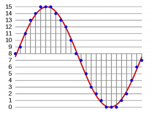
PCM Sampling
This image shows the process of sampling and quantization. Image Credit :anonymous, PcmCC BY-SA 3.0

Operations in the Transmitter:

Sampling

The message signals pass under a process of sampling where they are sampled by the pulse signals. To reform the signal back to its original form, there is a specific condition for sampling rate. The rate must be the multiple of 2 or more of the greatest frequency component present in the signal.

Nyquist’s theorem is one of the important rule in the process of sampling. It deals with the sampling rate and necessary conditions for reconstruction of a signal after being sampled. The theorem is important not only for the Pulse Coded Modulations, but also for each and every modulation techniques and for every aspects of signal theories and signal applications. Mathematically, it says:

Fs >= 2 * Fmax

Here, Fs is the frequency of sampling and Fmax is the value of the greatest frequency component present in the signal.

Antialiasing filters plays a major role here. They omits specific frequency bands which are generally higher than the W.

Three different sampling methods
Image credit : Dr.J.L Mazher Iqbal Slideplayer Presentation

Encoding

Encoding refers to the process of conversion by which datas are symbolised through some specific symbols, or characters. This process brings more security to the communication system. That is why the process is important. For long transmission there is always possibility of unwanted interferences. Encoding saves us from those attacks.

In Pulse Coded modulation technique of transmission, the analog datas are converted to the digital signal. This part of operation is one of the important stage. It can be also stated as the ‘Stage of Digitization’.

The constant communication signal gets converted to distinct values. This distinct procedures in a code is called a code element or symbol. A code element or symbol is given by the discrete events in a code. As we know, the binary codes are given by Zeros and Ones.

Quantization

 “The Quantizing is a procedure of minimizing the extra unnecessary bits and limiting the data.”

State the advantages and disadvantages of PCM:

Advantages  of PCM

  • It transmits signals uniformly.
  • PCM has an efficient SNR.
  • PCM always offers efficient regeneration.

Disadvantages of PCM

  • Attenuation occurs due to noise and cross-talks.
  • PCM needs a larger bandwidth for transmission.
  • Other errors are also observed during transmission.

For more electronics related article click here

Pulse Amplitude Modulation (PAM): 5 Important Explanations

flat top 300x287 1

Subject of Discussion: Pulse Amplitude Modulation (PAM)

  • What is pulse amplitude modulation?
  • Flat top and natural PAM
  • What is PWM and PPM
  • Advantages and disadvantages of PAM
  • Comparison of PAM vs PWM vs PPM

What is Pulse Amplitude Modulation?

Definition of Pulse Amplitude Modulation:

“The modulation technique which is utilized to state the transfiguration of the analog signal to a pulse-type signals in that the amplitude of the pulse signifies the analog info”.

The modulator performs the primary steps while the conversion of analog signal to a Pulse Code Modulated Signal. In a number of application the Pulse Amplitude Modulation signal is used directly and complex conversion such as PCM is not at all required.

Types of Pulse Analog Modulation

The Pulse Analog Modulation can be classified into three categories. They are –

  1. Pulse Amplitude Modulation (PAM)
  2. Pulse width Modulation (PWM)
  3. Pulse Position Modulation

The relation between the pulse and constant amplitude of the message signal is proportional. As explained here, PAM is to a certain extent analogous to natural sampling technique, in which the message signal is multiplied by a periodic square pulses. In regular sampling process, however, the modulated square pulse is acceptable to vary with the message signal, however in pulse-amplitude modulation it is retained as flat signal.


Types of Pulse Amplitude Modulation

Pam can be categorized into two categories. They are – Flattop Pulse Amplitude Modulation and Natural Pulse amplitude modulation.

Flat Top Pulse Amplitude modulation:

The pulses’ amplitudes are dependent on the amplitude of the message signal.

Flat Top Pulse Amplitude modulation

Natural PAM:

Natural Pulse Amplitude modulation

Write down some of the Applications of PAM?

Applications of PAM

There are several applications of Pulse Amplitude modulation such as

  • PAM is used in Ethernet Communication.
  • PAM is used in many micro-controllers to generate some control signals.
  • In Photo-biology system, PAM is also used.

What are the advantages of PAM?

Advantages of Pulse Amplitude modulation

  • Pam is a better straightforward, less complex process for the modulations as well as demodulations.
  • The design of transmitters and receivers of PAM is quite a straightforward job and less complex than other design. 
  • Pulse Amplitude Modulation be able to produce other pulse modulation signals and transport the message signal at that time.

What are the disadvantages of PAM?

Disadvantages of Pulse Amplitude modulation

  • For PAM, bandwidth should be larger for transmission.
  • PAM has a great noise problem.
  • The PAM signal will changes, so that the power requisite for transmission may increase.

What is Pulse Width Modulation?

Definition of Pulse Width Modulation (PWM):

  •  “This is an analog modulating technique in which the duration, width, and time of the pulse carrier will be changed in proportion to the amplitude of the message signals.”
  • The pulses’ widths change in this technique. Though pulse’s magnitude remains the same.
  • In PWM, amplitude limiters are utilized as to create the amplitude of the signal as constant.

This PWM is also recognized as a Pulse Duration Modulation (PDM) and the Pulse Time Modulation (PTM) technique.

PWM
Pulse Width Modulation
An example of PWM in an idealized inductor driven by a voltage source modulated as a series of pulses, resulting in a sine-like current in the inductor.
Image source – ZureksPWM, 3-levelCC BY-SA 3.0
delta PWM
Principle of the delta PWM. Output signal (blue), limits (green).

Image Credit: Delta_PWM.png: Cyril BUTTAY derivative work: Krishnavedala (talk), Delta PWMCC BY-SA 3.0
Sigma Delta PWM

Image Credit :Sigma_delta.png: Cyril BUTTAY derivative work: Krishnavedala (talk), Sigma-delta PWMCC BY-SA 3.0

What is Pulse Position Modulation?

Definition of Pulse Position Modulation (PPM):

In the pulse-amplitude modulation or pulse-width modulation or pulse-length modulation technique, the pulse amplitude is the variable parameter, so it changes. The pulse’s period is one of the important parameter. The modulating signal is changes with the time of incidence of the leading or trailing edges, or both edges of the pulse.

Comparative analysis of PAM, PWM and PPM:

            PAM            PWM             PPM
In PAM amplitude keeps varying.In case of pulse amplitude modulation, the BW is dependent on the width of the following pulse.In PPM, the BW of the pulse is dependent on the rising-time of the pulse.
In PAM, the bandwidth depends on the width of the following pulse.In Pulse Width Modulation, Bandwidth is depended on the rising time of the pulseIn PPM, Bandwidth is depended on the rise time of the pulse
In Pulse amplitude Modulation (PAM) , System or circuit design is complex.In Pulse width modulation (PWM), System or circuit design is less complex.In Pulse position modulation (PPM), System or circuit design is less complex.
  High noise interference  Low noise interference  Low noise interference

For more electronics related article click here

Read more about Amplitude Modulation and Demodulation.

The Ultimate Guide to Digital Microscopes: Unlocking the Power of High-Resolution Imaging

digital microscope

Digital microscopes have revolutionized the world of microscopy, offering a range of advanced features and capabilities that surpass traditional optical microscopes. These powerful instruments provide researchers, scientists, and hobbyists with the ability to capture and analyze high-quality digital images with unprecedented precision and detail. In this comprehensive guide, we will delve into the technical specifications and advanced features of digital microscopes, equipping you with the knowledge to make informed decisions and unlock the full potential of these remarkable tools.

Resolution: Unveiling the Intricate Details

At the heart of digital microscopy lies the concept of resolution, which refers to the microscope’s ability to distinguish between two adjacent points. This critical factor is often measured in pixels per inch (PPI) or dots per inch (DPI). A high-quality digital microscope can produce images with a resolution of up to 1000 PPI, which is equivalent to 4K ultra-high definition (UHD) video. This level of detail allows users to observe and analyze the finest structures and features with remarkable clarity.

To understand the significance of resolution in digital microscopy, let’s consider a practical example. Imagine you are studying the intricate structure of a butterfly’s wing. With a traditional optical microscope, you may be able to see the overall pattern and general features of the wing. However, with a digital microscope boasting a resolution of 1000 PPI, you can delve deeper and observe the individual scales that make up the wing’s surface, revealing the intricate patterns and textures that are otherwise invisible to the naked eye.

Magnification: Expanding the Visible Realm

digital microscope

Magnification is another crucial factor in digital microscopy, as it determines the degree to which an image is enlarged. In digital microscopes, magnification is often expressed as a ratio of the size of the image on the screen to the size of the object being viewed. For instance, a digital microscope with a magnification of 100x can produce an image that is 100 times larger than the actual object.

This level of magnification allows users to explore the microscopic world in unprecedented detail. Imagine studying the structure of a single cell or the intricate patterns of a mineral crystal. With a digital microscope capable of 100x magnification, you can observe these tiny structures with remarkable clarity, unlocking a wealth of information and insights that would be impossible to discern with the naked eye.

Image Quality: Capturing the Essence of the Unseen

In addition to resolution and magnification, image quality is a crucial factor in digital microscopy. This aspect is often measured in terms of contrast, brightness, and color accuracy. High-quality digital microscopes are equipped with advanced imaging sensors and optics that can produce images with excellent contrast, brightness, and color fidelity.

Consider the study of a biological sample, such as a plant leaf or a tissue sample. With a digital microscope that offers superior image quality, you can observe the intricate cellular structures, the delicate patterns of the cell walls, and the vibrant colors of the chloroplasts with remarkable clarity. This level of detail and accuracy is essential for researchers and scientists who rely on microscopic observations to draw meaningful conclusions and make groundbreaking discoveries.

Software Capabilities: Unlocking the Power of Digital Analysis

The software capabilities of digital microscopes are equally important as their hardware specifications. Some digital microscopes come equipped with advanced software that can perform a wide range of image analysis tasks, such as measuring distances, counting objects, and identifying patterns.

Imagine you are studying the growth patterns of a bacterial colony. With a digital microscope that offers advanced software capabilities, you can not only capture high-resolution images of the colony but also use the software to precisely measure the size and distribution of individual bacterial cells. This level of quantitative analysis can provide invaluable insights into the growth dynamics and behavior of the colony, enabling you to draw more accurate conclusions and make informed decisions.

DIY Digital Microscopes: Exploring the Possibilities

While commercial digital microscopes offer a high level of performance and functionality, there are also opportunities for DIY enthusiasts to explore the world of digital microscopy. Some options include building a microscope using a smartphone or tablet camera, using a USB microscope, or constructing a microscope using a Raspberry Pi or Arduino board.

These DIY digital microscopes can be an excellent way to learn about the principles of microscopy and image analysis, as well as to experiment with different techniques and approaches. While they may not offer the same level of performance as commercial digital microscopes, they can still provide valuable insights and learning experiences for those interested in exploring the world of microscopy.

Quantifiable Data Points: Measuring the Capabilities

To further illustrate the impressive capabilities of digital microscopes, let’s consider some quantifiable data points:

  1. Resolution: A high-quality digital microscope can produce images with a resolution of up to 1000 PPI, which is equivalent to 4K ultra-high definition (UHD) video.
  2. Magnification: A digital microscope with a magnification of 100x can produce images that are 100 times larger than the object being viewed, making it possible to see details that are not visible with the naked eye.
  3. Measurement Accuracy: A digital microscope with advanced image analysis software can measure distances with an accuracy of ±0.1 microns, which is equivalent to 1/100th the width of a human hair.
  4. Image Formats: A digital microscope can capture images and videos in a wide range of formats, including JPEG, PNG, TIFF, and AVI, making it possible to share and analyze data in a variety of ways.

These data points highlight the remarkable capabilities of digital microscopes, demonstrating their ability to provide researchers, scientists, and hobbyists with unprecedented levels of detail, precision, and flexibility in their microscopic observations and analyses.

Conclusion

Digital microscopes have revolutionized the world of microscopy, offering a range of advanced features and capabilities that surpass traditional optical microscopes. By understanding the technical specifications and advanced features of these powerful instruments, you can unlock the full potential of digital microscopy and explore the microscopic world with unprecedented clarity and detail.

Whether you are a researcher, a scientist, or a hobbyist, the insights and capabilities provided by digital microscopes can open up new avenues of discovery and unlock a wealth of information about the intricate structures and processes that govern the natural world. By embracing the power of digital microscopy, you can push the boundaries of what is possible and contribute to the advancement of scientific knowledge and understanding.

References:

  1. Quantitative Analysis of Digital Microscope Images | Request PDF. (n.d.). Retrieved from https://www.researchgate.net/publication/6313881_Quantitative_Analysis_of_Digital_Microscope_Images
  2. Quantifying microscopy images: top 10 tips for image acquisition. (n.d.). Retrieved from https://carpenter-singh-lab.broadinstitute.org/blog/quantifying-microscopy-images-top-10-tips-for-image-acquisition
  3. Quantifying microscopy images: top 10 tips for image acquisition. (n.d.). Retrieved from https://forum.image.sc/t/quantifying-microscopy-images-top-10-tips-for-image-acquisition/12343

VBScript Procedures and VBScript Error Handling – An Excellent Guide for VBScript Tutorial 3 & 4

VBScript Procedures VBScript Sub Procedure 1 300x118 1

VBScript Tutorial – Table of Content

VBScript Tutorial #1: Overview of VBScript Variables 

VBScript Tutorial #2: VBScript Conditional Statements and Loops

VBScript Tutorial #3: VBScript Procedures

VBScript Tutorial #4: VBScript Error Handling and Execute VBScript

VBScript Tutorial #5: VBScript String Functions

VBScript Tutorial #6: VBScript Date Functions

VBScript Tutorial #7: VBScript Time Functions

VBScript Tutorial #8: VBScript Array Functions

In this VBScript Tutorial, we are going to learn about VBScript Procedures, including VBScript Functions and VBScript Sub Procedures. Also, we are going to learn about VBScript Error Handling and approaches to Execute VBScript through this tutorial.

VBScript Tutorial #3: VBScript Procedures

VBScript Procedures:

VBScript procedures are the block of statements enclosed by special keywords to perform specific actions. VBScript procedures have the ability to accept input values and return the output value. Here, the input values are represented as the arguments. 

VBScript procedures are mainly used to organize the codes in a professional way for code reusability and better maintenance. Let’s assume a big program or codes have some basic arithmetic operation is performed repetitively. So, if there is a change in that operation, we need to change in every place where it’s used. Instead of doing the same, if we write one VBScript procedure for the same operation and use the reference of that in all the places, then we need to change the code in one place. In this way, we can reduce script maintenance efforts.

VBScript procedures can be referred to by using the keyword “Call”. Also, VBScript allows calling any procedure without using this keyword.

The Advantages of VBScript Procedures:

· Code reusability.

· Reduce script maintenance efforts.

· Better readability of codes.

· Better organization of codes.

Types of VBScript Procedures:

The VBScript procedures are accepting inputs, process it and perform some operation based on the types of procedure. Broadly, VBScript procedures are classified into two types which ate specified below – 

· VBScript Sub procedure

· VBScript Function procedure

VBScript Sub Procedures:

The VBScript sub procedures group multiple statements without returning any output values. It can accept the inputs as arguments. This type of procedures is to start and end with Sub and End Sub keywords, respectively. VBScript Sub procedures can accept arguments but do not return any output values. 

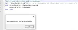
Example – Here we will write a small vbscript sub procedure which accept an argument as alert messages and display it in a popup message box.

‘Call the vbscript sub procedure
Call displayAlert(“This is an example of vbscript sub procedure”) 
Sub displayAlert(alertMessage)
\tMsgbox alertMessage
End Sub
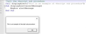
VBScript Procedures - VBScript Sub Procedure
VBScript Procedures – VBScript Sub Procedure

VBScript Function:

If we want to execute a block of statements with returning any output values, we need to use VBScript functions. At the beginning of the VBScript functions, we need to use “Function” keyword to define the function name and at the end the “End Function” keyword is used. VBScript Functions can accept arguments as well as return values. To return value from a function, the value has to be assigned to the function name before closing the function.

Example – In this example, we will calculate the circle area using a vbscript function. Here, the radius will be passed as an argument to the VBScript function and return the area as output.

Dim calcArea 
'Call the vbscript function
calcArea = calcCircleArea(7)
msgbox "The area of the circle is " & calcArea 
Function calcCircleArea(radius)
\tdim pi, a
\tpi = 22/7
\ta = pi*radius*radius
\tcalcCircleArea = a
End Function
Output(Message Box): The area of the circle is 154

ByRef and ByVal Arguments in VBScript Procedures:

ByRef Argument – To keep the changes made in the argument even after the VBScript procedure is called, then we have to send the argument by reference(ByRef). If there is nothing is specified when passing arguments into the VBScript procedures, by default it’s treated as passed by reference. The keyword ByRef is used to pass the argument by reference.

Example of ByRef – Refer below code, here argument Counter has been passed by reference into the procedure. Initially, it’s defined with value four, and in the procedure, it’s incremented by 1. As the argument has been passed by reference, the value of the argument will be five after the function call.

Function incrementCounter(ByRef Counter)
   Counter = Counter +1
   incrementCounter = Counter
End Function
Dim x
myCounter=4
call incrementCounter(myCounter)
msgbox myCounter

Output => 5

ByVal Argument – When an argument is passed by value(ByVal), any modification, done on the argument’s value in the VBScript functions, will not persist after the function call. The keyword ByVal is used to pass the argument by value.

Example of ByVal – Refer below code, here argument Counter has been passed by value into the procedure. Initially, it’s defined with value four, and in the procedure, it’s incremented by 1. As the argument has been passed by value, the value of the argument will remain four after the function call.

Function incrementCounter(ByVal Counter)
   Counter = Counter +1
   incrementCounter = Counter
End Function
Dim x
myCounter=4
call incrementCounter(myCounter)
msgbox myCounter

Output => 4

VBScript Tutorial #4: VBScript Error Handling & Execute VBScript

VBScript Errors:

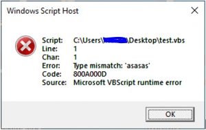
VBScript errors are nothing but unhandled events which is not handled through the code. In vb scripting, if any events are encountered which are not handled through the codes, they are treated as VBScript errors.

Types of VBScript Errors: 

The different types of VBScript errors are mentioned below – 

Syntax Errors – The primary reasons for this type of VBScript errors are the incorrect structure of the script, typographical errors, incorrect spelling of keywords, syntactical errors. If the syntax errors exist, the script will not be executed at all. It appears during the compilation time of the script. 

Logical Errors – This type of VBScript errors are appeared due to some unexpected events such as number, or date conversion failed due to inappropriate data. It appears while the test scripts are getting executed.

VBScript Errors
VBScript Errors

VBScript Error Handling:

It is not possible to handle all the unexpected VBScript errors through coding. So, it’s the first priority to handle VBScript errors. Primarily, there is one approach to handle the VBScript error in the scripts. This approach is the combination of using “On Error Resume Next” statements and Err Object’s property.

On Error Resume Next statements: 

It was using the On-Error- Resume-Next statements; the exception can be handled partially. In this approach, the test script block should be started with “On Error Resume Next” statements. It signifies that in case of any error, execution will be skipped the current step and proceed with next step. After that, by checking the Error, we can handle the exceptions. Important keywords are –

· On Error Resume Next – In case of Error, VBScript will not raise an error message; instead of that, execution will move to the next step.

· On Error Goto 0 – It will work in reverse procedure with comparison to the above keyword. So, after execution of this step, VBScript will throw errors in case of any exceptions.

· Error.Description – It stores the error description.

· Error.Number – It holds the error number. For success, the value is zero.

· Error.Clear – It reset the Error object.

 On Error Resume Next
\t'Vbscript statement 1
\t. . . . .
\tIf error.number <> 0 then 'Checking for error
\t\t'..Handle the error
\tElse 'Success condition no need to handle anything
\t\tError.Clear
\tEnd If
On Error Goto 0

Approach to Execute VBScript:

There are different ways that are available to execute VBScripts. The most used approaches are –

  • Execute VBScript through .vbs file
  • Execute VBScript as a part of HTML web development

Execute VBScript through .vbs file: The steps to execute vbscript through .vbs file are –

  1. Write VBScript codes in a simple flat file. Any editor such as, note pad, Note Pad++, Edit Plus, etc can be used to create the file.
  2. Save the file with .vbs extension.
  3. Execute the file by double-clicking on it.
  4. Same file can be executed through the command prompt using the full file path. Command to execute vbs file is WScript “<file_name_with_path>”.

Through out this vbscript tutorial, we are using this approach to run all the demo vbscripts.

Execute VBScript as a part of the web page: In this approach, we need to write the VBScript codes with in tag <script> in the web page. The syntax will be looks like below –

<script type="text/vbscript">
-\tVbscript statements …
</script>

This approach is used while developing web pages using the classic ASP. Also same can be used in other technologies like PHP, JSP etc.

Tools Uses VBScript:  The major tools which supports vbscripts are – UFT,  Excel Macro, Visual Basic, Classic ASP (client side scripting)

Conclusion:

In this VBScript article, we have learned about the learn about VBScript Procedures and VBScript Error Handling through this tutorial. We hope this tutorial has helped a lot to brush up on your basics of VB Scripting. To get more information on VBScripting, please click here.


Coordinate Geometry: 3 Things Most Beginner’s Don’t Know

image2 3 300x244 1

Coordinate Geometry

Today we are here to discuss Coordinate Geometry from the root of it. So, The whole article is about what Coordinate Geometry is, relevant problems and their solutions as much as possible.

(A) Introduction

Coordinate Geometry is the most interesting and important field of Mathematics. It is used in physics, engineering and also in aviation, rocketry, space science, spaceflight etc.

To know about Coordinate Geometry first we have to know what Geometry is.
In greek ‘Geo’ means Earth and ‘Metron’ means Measurement i.e. Earth Measurement. It is the most ancient part of mathematics, concerned with the properties of space and figures i.e positions, sizes, shapes, angles and dimensions of things.

What is Coordinate Geometry?

Coordinate geometry is the way of learning of geometry using the Co-ordinate system. It describes the relationship between geometry and algebra.
Many mathematicians also called Coordinate geometry as Analytical Geometry or Cartesian Geometry.

Why is it called Analytical Geometry?

Geometry and Algebra are two different branches in Mathematics. Geometrical shapes can be analyzed by using algebraic symbolism and methods and vice versa i.e. algebraic equations can be represented by Geometric graphs. That is why it is also called Analytical Geometry.

Why is it called Cartesian Geometry?

Coordinate Geometry was also named Cartesian Geometry after French mathematician Rene Descartes as he independently invented the cartesian coordinate in the 17th century and using this, put Algebra and Geometry together. For such a great work Rene Descartes is known as the Father of Coordinate Geometry.

(B) Coordinate system

A Coordinate system is the base of Analytical Geometry. It is used in both two dimensional and three-dimensional fields. There are four types of coordinate system in general.

Coordinate Geometry
Coordinate Geometry

(C) The whole subject of coordinate Geometry is divided into two chapters.

  1. One is ‘Coordinate Geometry in Two Dimensions’.
  2. The second one is ‘Coordinate Geometry in Three Dimensions’.

Coordinate Geometry in Two Dimensions (2D):

  1. Here we are going to discuss both the Cartesian and Polar Coordinates in two dimensions one by one. We will also solve some problems to get a clear idea of the same, and later we will find the relation between them as well.

Cartesian Coordinate in 2D:

At first, we will have to learn the following terms through graphs.
i) Coordinate Axes
ii) Origin
iii)Coordinate Plane
iv) Coordinates
v) Quadrant

Read and Follow the Figures simultaneously.

image5 1
Coordinate Geometry Graph 1

Suppose the horizontal line XXand vertical line YY are two perpendicular lines intersecting each other at right angles at the point O , XXand YY are number lines, the intersection of XXand YY forms XY-plane and P is any point on this XY-plane.

Coordinate Axes in 2D

Here XX and YY are described as the Coordinate Axes. XX is indicated by X-Axis and YY is indicated by Y-Axis. Since XX and YY are number lines, the distances measured along OX and OY are taken as positive and also the distances measured along OX and OY are taken as negative. (See above graph.1)

What is Origin in 2D?

The point O is called the Origin. O is always supposed to be the starting point. To find the position of any point on the coordinate plane we always have to begin the journey from the origin. So the origin is called the Zero Point. (Please refer the above graph.1)

What do we understand by a Coordinate Plane?

The XY plane defined by two number lines XX and YY or the X-axis and Y- axis is called the Coordinate Plane or Cartesian Plane. This Plane extends infinitely in all direction. This is also known as two-dimensional plane. (See above graph.1)

image2 3
Coordinate Plane Graph 2

*Assume the variables x>0 and y>0 in the above figure.

What is Coordinate in 2D?

Coordinate is a pair of numbers or letters by which the position of a point on the coordinate plane is located. Here P is any point on the coordinate plane XY. The coordinates of the point P is symbolized by P(x,y) where x is the distance of P from Y axis along X axis and y is the perpendicular distance of P from X axis respectively. Here x is called the abscissa or x-coordinate and y is called the ordinate or y-coordinate (See above Graph 2)

image8
Coordinate in 2D Graph 3

How to Plot a Point on the coordinate plane?

Always we will have to start from the origin and first walk towards right or left along X axis to cover the distance of x-coordinate or abscissa ,then turn the direction up or down perpendicularly to the X axis to cover the distance of ordinate using units and their signs accordingly. Then we reach the required point .

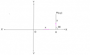
Here to represent the given point P(x,y) graphically or to plot it on the given XY plane, first start from the origin O and cover the distance x units along X axis (along OX) and then turn at 90 degree angle with X axis or parallelly to Y axis(here OY) and cover the distance y units . (See above graph 3)

How to find coordinates of a given point in 2D ?

image6
Coordinate Geometry Graph 4

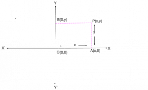
Let XY be the given plane,O be the origin and P be the given point.
First draw a perpendicular from the point P on X axis at the point A. Suppose OA=x units and AP=y units, then the Coordinates of the point P becomes (OA , AP) i.e. (x,y).

Similarly if we draw another perpendicular from the point P on Y axis at the point B, then BP=x and OB=y.
Now since A is the point on the X axis ,the distance of A from Y axis along X axis is OA=x and perpendicular distance from X axis is zero,so the coordinates of A becomes (x,0).
Similarly, the coordinates of the point B on the Y axis as (0,y) and the coordinates of Origin O is (0,0).

image4 1
Coordinate Geometry- Graph 5

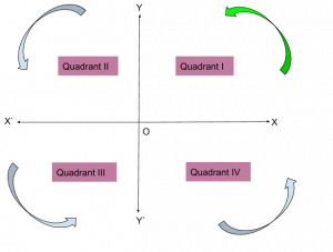
Graph 5 * colour green denotes the beginning

What is Quadrant in 2D?

Coordinate Plane is divided into four equal sections by the coordinate axes. Each section is called Quadrant. Going around counterclockwise or anticlockwise from upper right, the sections are named in the order as Quadrant I, Quadrant II, Quadrant III and Quadrant iv.

Here we can see the X and Y axes divide the XY plane into four sections XOY, YOX, XOY and YOX accordingly. Therefore, the area XOY is the Quadrant I or first quadrant, YOX is the Quadrant II or second quadrant, XOY is the Quadrant III or third quadrant and YOX is the Quadrant IV or fourth quadrant.(please refer the graph 5)

Coordinate Geometry
Graph 6

Points in Different Quadrants of coordinate plane:

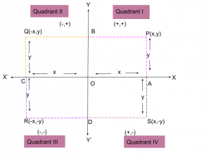
Since OX is +ve and OX is -ve side of X axis and OY is +ve and OY is -ve side of Y axis, signs of coordinates of points in different quadrants—-
Quadrant I: (+,+)
Quadrant II: (-,+)
Quadrant III: (-,-)
Quadrant IV: (+,-)

For example, if we go along OX from O and draw a perpendicular from any point P in the Quadrant I on the X axis (OX) at the point A so that OA=x and AP=y then coordinate of P is defined as (x,y) as described in the article (How to find coordinate of a given point?).


Again if we go along OX from O and draw a perpendicular from any point Q in the Quadrant II on the X axis (on OX) at the point C so that OC=x and CQ=y then the coordinates of Q is defined as (-x,y).
Similarly the coordinates of any point R in quadrant III is defined as (-x,-y) and the coordinates of any point in quadrant IV is defined as (x,-y). (see graph 6)

Conclusion

 The brief information about Coordinate Geometry with basic concepts has been provided to get a clear idea to start the subject. We will subsequently discuss details about 2D and 3D in the upcoming posts. If you want further study go through:

Reference

  1. 1. https://en.wikipedia.org/wiki/Analytic_geometry
  2. 2. https://en.wikipedia.org/wiki/Geometry

For more topics on Mathematics, please follow this Link .

15 Examples Of Permutations And Combinations

Image Permutations and Combinations

Illustration of the concept Permutations and Combinations by the examples

In this article, we have discussed some examples which will make the foundation strong of the students on Permutations and Combinations to get the insight clearance of the concept, it is well aware  that the Permutations and combinations both are the process to calculate the possibilities, the difference between them is whether order matters or not, so here by going through the number of examples we will get clear the confusion where to use which one.

The methods of arranging or selecting a small or equal number of people or items at a time from a group of people or items provided with due consideration to be arranged in order of planning or selection are called permutations.

Each different group or selection that can be created by taking some or all of the items, no matter how they are organized, is called a combination.

Basic Permutation (nPr formula) Examples

            Here We are making group of n different objects, selected r at a time equivalent to filling r places from n things.

The number of ways of arranging = The number of ways of filling r places.

nPr = n. (n-1). (n-2)…(n-r+1) = n/(n-r)!

CodeCogsEqn 3

so nPr formula we have to use is

nPr = n!/(n-r)!

Example 1): There is a train whose 7 seats are kept empty, then how many ways can three passengers sit.

solution: Here n=7, r=3

so      Required number of ways=

nPr = n!/(n-r)!

7P3 = 7!/(7-3)! = 4!.5.6.7/4! = 210

In 210 ways 3 passengers can sit.

Example 2) How many ways can 4 people out of 10 women be chosen as team leaders?

solution: Here n=10, r=4

so      Required number of ways=

nPr = n!/(n-r)!

10P4 = 10!/(10-4)! = 6!7.8.9.10/6! = 5040

In 5040 ways 4 women can be chosen as team leaders.

Example 3) How many permutations are possible from 4 different letter, selected from the twenty-six letters of the alphabet?

solution: Here n=26, r=4

so      Required number of ways=

nPr = n!/(n-r)!

26P4 = 26!/(26-4)! = 22!.23.24.25.26/22! = 358800

In 358800 ways, 4 different letter permutations are available.

Example 4) How many different three-digit permutations are available, selected from ten digits from 0 to 9 combined?(including 0 and 9).

solution: Here n=10, r=3

so      Required number of ways=

nPr = n!/(n-r)!

10P3 = 10!/(10-3)! = 7!.8.9.10/7! = 720

In 720 ways, three-digit permutations are available.

Example 5) Find out the number of ways a judge can award a first, second, and third place in a contest with 18 competitors.

solution: Here n=18, r=3

so      Required number of ways=

nPr = n!/(n-r)!

18P3 = 18!/(18-3)! = 15!.16.17.18/15! = 4896

Among the 18 contestants, in 4896 number of ways, a judge can award a 1st, 2nd and 3rd place in a contest.

Example

6) Find the number of ways, 7 people can organize themselves in a row.

solution: Here n=7, r=7

so      Required number of ways=

nPr = n!/(n-r)!

7P7 = 7!/(7-7)! = 7!/0! = 5040

In 5040 number of ways, 7 people can organize themselves in a row.

Examples based on Combination (nCr formula/ n choose k formula)

The number of combinations (selections or groups) that can be set up from n different objects taken r (0<=r<=n) at a time is

gif

This is commonly known as nCr or n choose k formula.

nCk = n!/k!(n-k)!

Examples:

1) If you have three dress with different colour in red, yellow and white then can you find a different combination you get if you have to choose any two of them?

Solution: here n=3, r=2 this is 3 CHOOSE 2 problem

nCr = n!/r!(n-r)!

3C2 = 3!/2!(3-2)! = 2!.3/2!.1 = 3

In 3 different combination you get any two of them.

2) How many different combinations can be done if you have 4 different items and you have to choose 2?

Solution: here n=4, r=2 this is 4 CHOOSE 2 problem

nCr = n!/r!(n-r)!

4C2 = 4!/2!(4-2)! = 2!.3.4/2!.2! = 6

In 6 different combination you get any two of them.

3) How many different combinations can be made if you have only 5 characters and you have to choose any 2 among them?

Solution: here n=5, r=2 this is 5 CHOOSE 2 problem

nCr = n!/r!(n-r)!

5C2 = 5!/2!(5-2)! = 3!.4.5/2!.3! = 10

In 10 different combination you get any two of them.

4) Find the number of combinations 6 choose 2.

Solution: here n=6, r=2 this is 6 CHOOSE 2 problem

nCr = n!/r!(n-r)!

6C2 = 6!/2!(6-2)! = 4!.5.6/2!.4! = 15

In 15 different combination you get any two of them.

5) Find the number of ways of choosing 3 members from 5 different partners.

Solution: here n=5, r=3 this is 5 CHOOSE 3 problem

nCr = n!/r!(n-r)!

5C3 = 5!/3!(5-3)! = 3!.4.5/3!.2! = 10

In 10 different combination you get any three of them.

6) Box of crayons having red, blue, yellow, orange, green and purple. How many unlike ways can you use to draw only three colour?

Solution: here n=6, r=3 this is 6 CHOOSE 3 problem

nCr = n!/r!(n-r)!

6C3 = 6!/3!(6-3)! = 3!.4.5.6/3!.3.2.1 =20

In 20 different combination you get any three of them.

7) Find the number of combinations for 4 choose 3.

Solution: here n=4, r=3 this is 4 CHOOSE 3 problem

nCr = n!/r!(n-r)!

4C3 = 4!/3!(4-3)! = 3!.4/ 3!.1! = 4

In 4 different combination you get any three of them.

8) How many different five-person committees can be elected from 10 people?

Solution: here n=10, r=5 this is 10 CHOOSE 5 problems

nCr = n!/r!(n-r)!

10C5 = 10!/5!(10-5)! = 10!/5!.5! = 5!.6.7.8.9.10/5!.5.4.3.2 = 7.4.9 =252

So 252 different 5 person committees can be elected from 10 people.

9) There are 12 volleyball players in total in college, which will be made up of a team of 9 players. If the captain remains consistent, the team can be formed in how many ways.

Solution: here as the captain already has been selected, so now among 11 players 8 are to be chosen n=11, r=8 this is 11 CHOOSE 8 problem

nCr = n!/r!(n-r)!

11C8 = 11!/8!(11-8)! = 11!/8!.3! = 8!.9.10.11/8!.3.2.1 = 3.5.11 = 165

So If the captain remains consistent, the team can be formed in 165 ways.

10) Find the number of combinations 10 choose 2.

Solution: here n=10, r=2 this is 10 CHOOSE 2 problem

nCr = n!/r!(n-r)!

10C2 = 10!/2!(10-2)! = 10!/2!.8! = 8!.9.10/2!.8! = 5.9 = 45

In 45 different combination you get any two of them.

We have to see the difference that nCr is the number of ways things can be selected in ways r and nPr is the number of ways things can be sorted by means of r. We have to keep in mind that for any case of permutation scenario, the way things are arranged is very very important. However, in Combination, the order means nothing.

Conclusion

A detailed description with examples of the Permutations and combinations has been provided in this article with few real-life examples, in a series of articles we will discuss in detail the various outcomes and formulas with relevant examples if you are interested in further study go through this link.

Reference

  1. SCHAUM’S OUTLINE OF Theory and Problems of DISCRETE MATHEMATICS
  2. https://en.wikipedia.org/wiki/Permutation
  3. https://en.wikipedia.org/wiki/Combination

Fluorescence Microscopy: A Comprehensive Guide for Science Students

fluorescence microscopy

Fluorescence microscopy is a powerful analytical technique that allows researchers to visualize and quantify specific molecules within biological samples. This method relies on the excitation of fluorescent molecules, known as fluorophores, and the subsequent detection of the emitted light. The accuracy and precision of quantitative fluorescence microscopy measurements are crucial for reliable data acquisition, making it an essential tool in life sciences research.

Pixel Size and Spatial Resolution

The pixel size of a digital image is a key factor in fluorescence microscopy, as it directly determines the spatial resolution of the image. Pixel size is typically measured in micrometers (µm) or nanometers (nm) and represents the smallest distance between two distinguishable points in the image.

For example, a pixel size of 0.1 µm would correspond to a spatial resolution of 100 nm, meaning that the microscope can resolve features as small as 100 nm. This level of resolution is essential for visualizing and quantifying subcellular structures, such as organelles, protein complexes, and individual molecules.

The relationship between pixel size and spatial resolution can be expressed mathematically as:

Spatial Resolution = Pixel Size × Nyquist Sampling Criterion

The Nyquist Sampling Criterion states that the sampling rate (i.e., pixel size) must be at least twice the highest spatial frequency of the image to avoid aliasing artifacts. This means that the pixel size should be no larger than half the desired spatial resolution.

Field of View (FOV)

fluorescence microscopy

The field of view (FOV) is the area of the sample that is visible in the microscope’s viewfinder. It is typically measured in square micrometers (µm²) and depends on the objective lens’s magnification and the camera’s sensor size.

For instance, a 20x objective lens with a 0.5 µm pixel size and a camera sensor size of 1/2.3″ would result in a FOV of approximately 0.5 mm². This information is crucial for determining the spatial scale of the acquired images and for planning experiments that require the visualization of specific regions within a sample.

The FOV can be calculated using the following formula:

FOV = (Sensor Width × Sensor Height) / (Objective Magnification × Pixel Size)^2

where the sensor width and height are typically given in micrometers (µm).

Dynamic Range

The dynamic range of a camera is the ratio between the maximum and minimum detectable signal levels. It is usually measured in bits and represents the camera’s ability to capture a wide range of signal intensities.

For example, a 12-bit camera has a dynamic range of 4096:1, while a 16-bit camera has a dynamic range of 65536:1. A higher dynamic range allows the camera to capture more subtle variations in fluorescence intensity, which is essential for quantitative analysis.

The dynamic range can be calculated as:

Dynamic Range = 2^Bit Depth

where the bit depth is the number of bits used to represent the pixel values.

Signal-to-Noise Ratio (SNR)

The signal-to-noise ratio (SNR) is the ratio of the signal intensity to the background noise. It is usually measured in decibels (dB) and represents the camera’s ability to distinguish between the signal and the noise.

For example, an SNR of 60 dB would correspond to a signal that is 1000 times stronger than the noise. A high SNR is crucial for accurate quantification of fluorescence signals, as it ensures that the measured intensities are primarily due to the target molecules and not to background noise.

The SNR can be calculated as:

SNR = 20 × log10(Signal Intensity / Noise Intensity)

where the signal and noise intensities are typically measured in arbitrary units (a.u.).

Excitation and Emission Wavelengths

Fluorescence microscopy relies on the excitation and emission of specific wavelengths of light. The excitation wavelength is the wavelength of light used to excite the fluorophore, while the emission wavelength is the wavelength of light emitted by the fluorophore.

For example, GFP (Green Fluorescent Protein) has an excitation peak at 488 nm and an emission peak at 509 nm. The choice of fluorophore and the corresponding excitation and emission wavelengths is crucial for the specific labeling and visualization of target molecules within a sample.

The relationship between the excitation and emission wavelengths can be described by the Stokes shift, which is the difference between the excitation and emission wavelengths. A larger Stokes shift is generally desirable, as it allows for better separation of the excitation and emission light, reducing the risk of interference and improving the signal-to-noise ratio.

Quantum Efficiency (QE)

The quantum efficiency (QE) of a camera is the ratio of the number of detected photoelectrons to the number of incident photons. It is usually measured as a percentage and represents the camera’s ability to convert incoming photons into detectable signals.

For example, a camera with a QE of 50% would detect 50 photoelectrons for every 100 incident photons. A higher QE is desirable, as it indicates that the camera is more efficient at converting the available photons into a measurable signal, leading to improved image quality and sensitivity.

The QE can be calculated as:

QE = (Number of Detected Photoelectrons) / (Number of Incident Photons) × 100%

Photon Budget

The photon budget is the total number of photons available for detection in a given imaging scenario. It depends on the excitation light intensity, the fluorophore’s brightness, and the camera’s sensitivity.

For example, a photon budget of 10^6 photons would correspond to a signal that is strong enough to be detected with high SNR. Maximizing the photon budget is crucial for improving the image quality and the reliability of quantitative measurements, as it ensures that the detected signal is well above the noise level.

The photon budget can be calculated as:

Photon Budget = (Excitation Light Intensity) × (Fluorophore Brightness) × (Camera Sensitivity)

where the excitation light intensity is typically measured in photons/s/µm², the fluorophore brightness is measured in photons/s/molecule, and the camera sensitivity is measured in photoelectrons/photon.

By understanding and applying these quantifiable details, researchers can optimize their fluorescence microscopy experiments, ensuring reliable and reproducible data acquisition. This knowledge is essential for science students and researchers working in the life sciences field, as it provides a solid foundation for the effective use of this powerful analytical technique.

References:
– Culley Siân Caballero Alicia Cuber Burden Jemima J Uhlmann Virginie, Made to measure: An introduction to quantifying microscopy data in the life sciences, 2023-06-02, https://onlinelibrary.wiley.com/doi/10.1111/jmi.13208
– Quantifying microscopy images: top 10 tips for image acquisition, 2017-06-15, https://carpenter-singh-lab.broadinstitute.org/blog/quantifying-microscopy-images-top-10-tips-for-image-acquisition
– A beginner’s guide to improving image acquisition in fluorescence microscopy, 2020-12-07, https://portlandpress.com/biochemist/article/42/6/22/227149/A-beginner-s-guide-to-improving-image-acquisition
– Principles of Fluorescence Spectroscopy, Joseph R. Lakowicz, 3rd Edition, Springer, 2006.
– Fluorescence Microscopy: From Principles to Biological Applications, Edited by Ulrich Kubitscheck, 2nd Edition, Wiley-VCH, 2017.
– Fluorescence Microscopy: Super-Resolution and other Advanced Techniques, Edited by Ewa M. Goldys, 1st Edition, CRC Press, 2016.