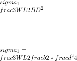
Shear Strain: 31 Facts You Should Know

Shear strain Shear velocity 300x300 1

What is shear strain?

Shear strain is the ratio of change in dimensions to the original dimension due to shear stress and deformation perpendicular rather than parallel to it. Shear strain results from the use of 2 parallel and opposite forces working at the surfaces of an object.

Shear strain formula:

Shear strain=ΔxL0/L.

Shear Modulus:

“This is the constant of proportion and is well-defined by the ratio of stress to strain.”

Shear modulus is generally represented by S.

S=shear-stress. / shear-strain.

Shear strain units:

This is dimensionless quantity, so this is Unitless.

Shear strain symbol:

Shear strain symbol=γ or ε

Shear strain unit:

1, or radian

Shear strain from axial strain

Strain:

Applied loads or displacements lead to change in dimensions. For the uniaxial displacement, the axial strain defined basically as the ratio of the variation in length to the actual length.

Shear stress strain diagram

The three-dimensional strain components may also be represented as simple axial strains and shear-strains. The displacement vectors (u,v,w) acting along the axes (x,y,z) respectively.
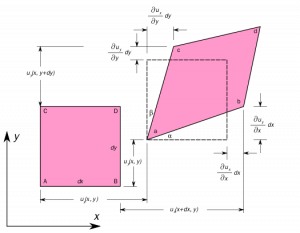
deformation 1
Image credit : Wikipedia

The uniaxial strain in x-direction due to displacement gradient,

1 3

Similarly, the shear-strain in the y-direction due to displacement gradient is given by,

2 3

The shear-strain components are represented as strain matrix as following,

4 1

Three shear-strains are the strains represented in all planes in x,y,z directions as XY, YZ, XZ.

The strains are represented in the strain matrix-induced due to the stress:

5 1

Strain Measurement:

It is difficult to measure stress directly. So, the strain measurement can be done using electric resistance circuit gauges connected to it.

Strain gauge measurement | Shear strain from a strain gauge

The strain gauge measurement is used to determine the resistance of the wire foiled together to the conducting substrate. The wire resistance is R,

\\frac{\\Delta R}{R}= K.\\varepsilon

where K recognized as strain-factor

Alternatively,

\\varepsilon= deformation = strain

so, strain can be induced by using strain measurement.

Since the strains are low, the Wheatstone bridge needs to determine the resistances. The galvanometer reading has to be zero to find out the resistances R1, R2, R3, R4. More than one configuration can be used to measure the strain. A half wiring can be used and attached to the other gauges. There are one active meter and one dummy meter. The dummy gauge reduces the temperature effects by canceling out them. Such difference can lead to an improvement in the accuracy of the circuits.

Maximum shear strain equation:

Maximum normal strain (εmax.)

(εx+εy)/2+(((εx-εy)/2)2+(γxy/2)2)0.5.

Minimum normal strain (εmin).

(εx+εy)/2-(((εx-εy)/2)2+(γxy/2)2)0.5.

Maximum shear-strain (in-plane) ( γmax (in-plane)).

((εx-εy)2+(γxy)2)0.5

Principal angle (θp)

[atan(γxy/(εx-εy))]/2

Principal shear strain:

Principal Stress:

Shear stress is zero at an alignment then principal stress happens.

Principal Angle:

This is the angle of alignment in that principal stress will occur for a definite point.

Principal Strain:

This is the highest and least normal strain possible for an material at that specific point and shear-strain is zero at the angle where principal strain occurs.

The 3 stresses normal to principal shear plane are termed principal-stress, where as in a plane where shear-strain is zero is termed as principal-strain.

Pure shear strain:

principal stress and strain are zero.

What is shear strain energy ?

Strain energy due to shear stress | Shear strain energy theory:

Maximum shear strain energy | Distortion energy (Von Mises) theory

The failure of utmost ductile material could have been determined by the shear stress theories or Von Mises theory as the failure occurs at the shearing of the materials. This theory can be represented as

(σ1−σ2)2+(σ2−σ3)2+(σ3−σ1)2=2σy2=constant

For  σ3 = 0,

The yield locus is an ellipse similar to sheer diagonal. In3D Stress system, this equation states the surface of a prism with circular cross section. More precisely a cylinder with its central axis along the line σ1 = σ2 = σ3.

The axis cut-thru the principal stress’s origin, and it is inclined at equal angle. when σ3 = 0,

The failure condition for ellipse formed by the intersection of the (σ1, σ2) plane with the inclined cylinder.

Shear strain energy per unit volume theory.

As per von Mises theory in 3D,the yield locus will be at the surface of the inclined cylinder. Points inside the cylinder show the safe points, whereas the points outside the cylinder show the failure conditions. The cylinder axis along σ1 = σ2 = σ3 line termed the hydrostatic stress line. It shows that the hydrostatic stress alone cannot give yield. It considers all the conditions altogether and shows that all cylinder points are safe.

Shear strain example problems

  • metal cutting
  • painting brush
  • Chewing gum
  • In river water case, river bed will experience the shear stress because of water flow situations.
  • During screen-sliding circumstance.
  • To Polishing a surface.
  • To write on surface, will experience shear-strain.

The following image of rectangular hut shows the deformation of rectangular into parallelogram due to shear-strain.

The reason behind shear strain:

Shear stress is the applied force that will cause deformation of a material by slippage along a plane or a plane parallel to the stress imposed on the surface of the object.

Relationship between shear stress and strain

Shear strain vs shear stress | shear strain vs shear force

The shear strain is the deformation caused due to shear stress. Shear stress is the stress occurred due to shear forces in-between the object’s parallel surfaces.

Torsional shear strain

Torsional shear-strain τ = shear stress (N/m2, Pa) T = applied torque (Nm)

The shear-strain is calculated by the angle of twist, the length, and the distance along the radius.

γ = shear strain (radians)

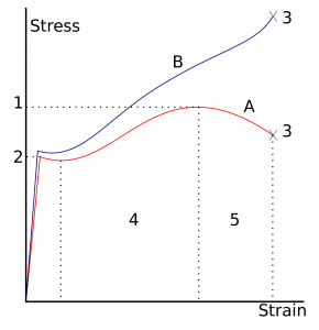
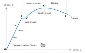
Shear stress strain curve:

Shear stress acts along the surface or parallel to the surface and may cause 1 layer to slide on others. shear stress leads to deforming the rectangular object into the parallelogram.

Shear stress acts to change the dimension and angle of the object.

Shear stress= F/A

Shear-strain: The shear-strain is the deformation amount to a given line rather than parallel.

Shear strain gamma

Shear-strain gamma= delta x/L.

The relationship between the shear stress and shear-strain for a specific material is acknowledged as that material’s shear.

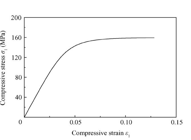
Shear stress strain curve Yield stress
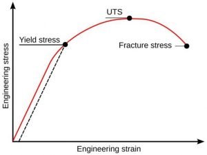
Shear strain curve
Image Credit: Wikipedia

Stress Strain curve Engineering and True
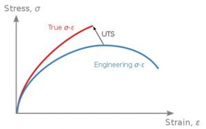
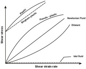
Variation of shear stress with rate of deformation
Stress strain curve 3
Image credit : nptel

Shear stress-strain curves are a significant graphical measure.

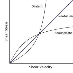
Shear Stress vs Shear velocity

Shear stress vs shear rate for dilatant and pseudoplastic non-Newtonian fluids compared to Newtonian fluid.

Shear strain Shear velocity
Image credit : DirectEON (talk) 08:46, 28 March 2008 (UTC), Dilatant-pseudoplasticCC BY-SA 3.0

Octahedral shear strain:

The octahedral shear stress/ strain gives the yield point of elastic material under a general stress state. The material displays yielding when the octahedral shear stress reach the extreme value of stress/strain. This is equivalent acknowledged as Von Mises yield criteria.

Shear strain rate :

The strain is the ratio of change in the length to its original length, so; shear-strain is a dimensionless quantity, so the strain-rate is in inversed time unit.

Shear strain formula in metal cutting:

Shear Plane Angle:

This is the angle between the horizontal plane and the shear plane, Significant for shear-strain applications in metal cutting.

The shear-strain rate at the shear plane, ϒAB is a function of cutting velocity and feed.

Difference between shear stress and Shear strain

Shear stress vs Shear strain:

Shear stress contemplates a block, which is subjected to a set of equal and opposite forces Q and this block recognized as bi-cycle-brake-block linked to wheel.There is a chance that one layer of the body slides on others, during shear stress initiation. If this failure is  not permitted, then a shear stress T will be formed.

Q – shear load shear stress (z) = area resisting shear A.

This shear stress will act on vertically to the area. The direct stresses will be at normal direction to the area of application though.

Considering bicycle brake block, the rectangular shaped blocks mightn’t be deformed after the baking force has been applied and block might change the shape in the form of strain.

The shear-strain is proportionate to the shear stress in the elastic range. The modulus of rigidity is represented as 

shear stress z shear strain y = – = constant = G

The constant G = the modulus of rigidity or shear modulus

Why do edge dislocations in crystal lattices introduce compressive tensile and shear lattice strains while screw dislocations only introduce shear strains ?

Because observational and pedagogical definition prescribes the coordinate frames in which this is true”, is probably the most accurate answer.

There are several approaches to visualizing the behavior of the strain fields around dislocations. The first approach is by direct observation; the second one borrows concepts from fracture mechanics. Both are equivalent.

  • An edge dislocation directed to the Burgers vector. Although a screw-dislocation directed perpendicularly to it.
  • The screw-dislocation ‘unzip’ the lattice as it travels thru it, creating a ‘screw’ or helical prearrangement of atom around the core.

Shear strain problems:

Problem : A rectangular block has area of 0.25m2. The height of the block is 10cm.A shearing force is applied to the top face of the block. And the displacement is 0.015mm.Find the stress, strain and shearing force. Modulus of rigidity= 2.5*10^10 N/m2

Given:

A= 0.25m2

H=10m

x=0.015mm

η =2.5*10^10N/m2.

Solution:

Shear strain = tan θ =X/H

                                   =0.015*10^-3/10*10^-2

                          tan θ =1.5*10^-3

Modulus of Rigidity = Shear stress/Shear strain

       2.5*10^10           = shear stress /0.0015

Shear stress               =2.5*10^10*1.5*10^-3

                                   =3.75*10^7 N/m2

Shear stress              =F/A

F                                = 3.75*10^7*0.25

                                  = 9.37*10^6 N.

Problem : A cube has side of 10 cm. The shearing force is applied on the upper side of the cube and the displacement is 0.75 cm by force of 0.25N. Calculate modulus of rigidity of the substance.

Given:

A= 10*10= 100 cm2

F=0.25N

H= 5cm

X=0.75cm

As we know,

Modulus of rigidity = Shear stress/Shear strain

Shear-strain is= X/H

                    =0.75/5

                    = 0.15

Shear Stress= F/A

                     = 0.25/100*10^-4

                     =25N.

Modulus of Rigidity = 25/0.15

                                   = 166.7 N/m^2

For more articles click here
Isothermal Process: 31 Things Most Beginner’s Don’t Know

piston cylinder 269x300 1

Content

Isothermal definition

An isothermal process is a thermodynamic process. In this isothermal process, the system’s temperature remains constant throughout the process. If we consider temperature is T. The temperature change is ΔT.

For the isothermal process, we can say that ΔT = 0

Isothermal expansion

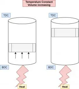
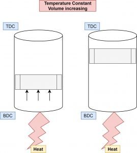
Isothermal expansion is increasing volume with a constant temperature of the system.

Isothermal – temperature constant

Expansion – Increasing volume

Isothermal Process : Expansion
Isothermal Expansion

Let’s consider the piston-cylinder arrangement for understanding if the piston moves from BDC (Bottom dead center) to TDC (Top dead center) with a constant temperature of the gas. This isothermal process is considered as Isothermal expansion.

Isothermal compression

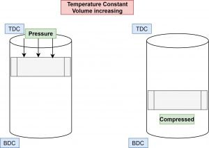
Isothermal compression is decreasing volume with a constant temperature of the system.

Isothermal – temperature constant

Compression – decreasing volume

piston cylinder 2
Isothermal Compression

Let’s consider another condition if the piston is moving from TDC to BDC (Bottom dead center) with a constant temperature of the gas. This isothermal process is considered Isothermal compression.

Isothermal vs adiabatic

Isothermal means Constant Temperature.

Adiabatic means Constant heat energy.

Some conditions for an isothermal process are :

  • The temperature should remain constant.
  • The variation must be happening at a slow rate.
  • Specific heat of the gas is infinite.

Some basic conditions for adiabatic are as below :

  • No heat transfer happens in adiabatic.
  • The variation must happen at a very speedy.
  • The specific heat of gas is 0 (Zero).

Isothermal calorimetry

It is one technique to find thermodynamic parameters’ interaction in a chemical solution. Using isothermal calorimetry, one can find binding affinity, binding stoichiometry, and enthalpy changes between two or more molecules interactions.

Isothermal amplification

It is one of the techniques used for pathogen monitoring. In this techniques, the DNA is amplified with keeping sensitivity higher than benchmark polymerase chain reaction (PCR)

Isothermal nucleic acid amplification

Isothermal amplification of nucleic acids is a technique that is efficient and faster accumulating nucleic acid at the isothermal process. It is a simple and efficient process. Since then, around 1990, many isothermal amplification processes have been developed as alternatives to a polymerase chain reaction (PCR)

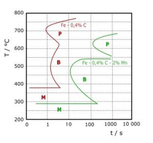
Isothermal transformation diagram

An isothermal transformation diagram is used to understand the kinetics of steel. It is also known as the time-temperature- transformation diagram.

375px T T T diagram
Time-temperature- transformation diagram Credit Wikipedia

It is associated with mechanical properties, microconstituents/microstructures, and heat treatments in carbon steels.

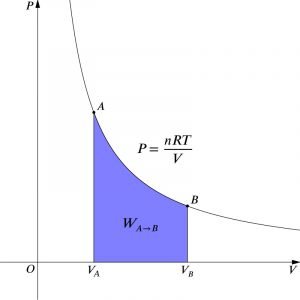
Isothermal PV diagram

800px Isothermal PV
Isothermal PV Diagram Credit Wikipedia

Isothermal process example

Isothermal is a process in which the system’s temperature remains unchanged or constant.

We can take the example of a refrigerator and heat pump. Here, in both cases, the heat energy is removed and added, but the system’s temperature remains constant.

Examples: Refrigerator, heat pump

Isothermal work

We have used the PV diagram above paragraph. If we want to write work done formula for it. We should consider the area under the curve A-B-VA-VB. The Work done for this integral can be given as,

W= nRT lnfrac{{Vb}}{Va}

Here in the equation,

n is the number of moles

R is gas constant

T is the temperature in kelvin

Isothermal layer

An isothermal layer term is used in atmospheric science. It is defined as a vertical layer of air or gas with constant temperature throughout height. This situation is happening at the troposphere’s low level in various advection situations.

Isothermal PCR

The full form of PCR is a polymerase chain reaction. This reaction is used in isothermal amplification techniques to amplify DNA.

Isothermal process equation

If we consider universal gas law, then the equation is given as below,

PV = nRT

Now, here this is in isothermal process, so T = Constant,

PV = constant

The above equation holds good for a closed system containing ideal gas.

We have discussed the work done earlier. We can consider that equation for the isothermal process. As we know from figure Vb is the final volume, and Va is the initial volume.

W= nRT lnfrac{{Vb}}{Va}

Isothermal expansion of an ideal gas

  • Isothermal – the temperature is constant.
  • Expansion – the volume is increasing.

It means that isothermal expansion increases volume with a constant temperature of the system.

In this condition, the gas is doing work, so the work will be negative because the gas applies energy to increase in volume.

The change in internal energy is also zero ΔU = 0 (Ideal gas, Constant temperature)

Wrev = -int_{Va}^{Va}P dV

Wrev = -int_{Va}^{Va}frac{nRT}{V} dV

Wrev = -nRTlnleft | frac{Vb}{Va} right |

Isothermal reversible expansion

This topic is covered in explaining the isothermal expansion of ideal gas.

Isothermal reaction

A chemical reaction occurring at one temperature, or we can say at a constant temperature, is an isothermal reaction. There no need for temperature change to continue reaction to end.

Isothermal irreversible expansion

An irreversible process is a real process we face in reality almost all the time. The system and its surrounding cannot be restored to their initial states.

Isothermal system

We have discussed the isothermal system in expansion and compression if we take piston-cylinder arrangement.

There are some assumptions for this system like,

  • There is no friction between piston and cylinder
  • There no heat or work loss from the system
  • The internal energy of the system should be constant throughout the isothermal process.

If we supply heat at the bottom of the cylinder, then the piston will move from BDC to TDC, as shown in Figure. It is an isothermal expansion. Similarly, in isothermal compression reverse, as we have explained earlier. This complete system is isothermal.

Isothermal bulk modulus

Bulk modulus is reciprocal of compressibility.

B(isothermal) = -frac{Delta P}{frac{Delta V}{V}}

Here, the term is the isothermal bulk modulus. It can be defined as the ratio of change in pressure to change in volume at a constant temperature. It is equal to P (pressure) if we solve the above equation.

Isothermal internal energy

We have discussed earlier that the constant temperature process’s internal energy remains constant.

Isothermal compressibility coefficient

The isothermal compressibility coefficient can be taken as the change of volume per unit change in pressure. It is also known as oil compressibility. It is widely used in resource estimation of oil or gas in petroleum study.

C(isothermal) = -frac{1}{V}cdot frac{Delta P}{Delta V}

Isothermal heat transfer

The expansion and compression process at constant temperature work on the principle of zero degradation energy. If the temperature is constant, then internal energy change and enthalpy change are zero. So, heat transfer is the same as work transfer.

If we heat the gas in any cylinder, then the gas’s temperature will increase. We want a system at a constant temperature, so we have to put one sink (cold source) to reject gained temperature.

Suppose we consider a cylinder with a piston. The gas will expand in the cylinder, and the piston gives displacement work due to getting heated. The temperature will stay constant in this case also.

Isothermal atmosphere

It can be defined as the there is no change in temperature with height in the atmosphere, and the pressure is decreasing exponentially with moving upward. It is also known as exponential atmosphere. We can say that the atmosphere is in hydrostatic equilibrium.

In this type of atmosphere, we can calculate the thickness between two adjacent heights with the equation given below,

Z2-Z1 =frac{RT}{g} lnfrac{P1}{P2}

Where,

Z1 & Z2 are two different heights,

P1 & P2 are Pressures at Z1 & Z2, respectively,

R is gas constant for dry air,

T is the virtual temperature in K,

g is gravitational acceleration in m/s2

Isothermal surface

Suppose we consider any surface flat, circular, or curvature, etc. If all the points on that surface are at the same temperature, then we can say that the surface is isothermal.

Isothermal conditions

As my word, we know that the system’s temperature must stay constant in this isothermal process. To keep the temperature constant, the system is free to change other parameters like pressure, volume, etc. It is also possible during this process, the work-energy and heat energy can be changed, but the temperature remains the same.

Isothermal zone

This word is generally used in atmospheric science. It is a zone in the atmosphere where the relative temperature is constant at some kilometer height. Generally, it is in the lower part of the stratosphere. This zone provides convenient aircraft conditions because of its constant temperature, general access to clouds and rains, etc.

Isothermal lines

This word is used in geography. Suppose we draw a line on a map of the earth for connecting different places whose temperature is the same or near to the same. It is known as an isothermal line in general.

Here, each point reflects the particular temperature for reading taken in a period of time.

Isothermal belt

In 1858 Silas McDowell of Franklin, given this name for western North Carolina, Rutherford, and Polk countries. This term is used for a season in these zones when one can grow fruits, vegetables, etc., easily due to temperature consistency.

Isothermal vs isobaric

Isothermal – temperature constant

Isobaric – Pressure constant

all process
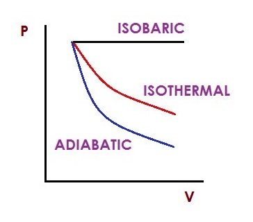
Isobaric, Isothermal and Adiabatic processes in PV Diagram

Let’s compare both processes for work done. According to the figure, you can notice both processes. As we know, that work done is an area under the integral. In the figure, we can easily see that the isobaric process area is more so obviously, work done more in isobaric. There is some condition for it. The initial pressure and volume should be the same. This is not true because we never get work during isobaric in any of the thermodynamic cycles. This topic is logical.

The correct answer depends on the type of condition that volume is increased or decreased in the process.

Isothermal vs isentropic

Isothermal – temperature constant

Isentropic – Entropy constant

Let’s consider the compression process to understand it,

In isothermal compression, the piston is compressing gas very slowly. As much slowly to maintain the constant temperature of the system.

Whereas in the case of isentropic, there should be no heat transfer possible between the system and surrounding. The isentropic compression will occur without heat transfer with constant entropy.

The isentropic process is similar to adiabatic, where there is no heat transfer. The system for the isentropic process should be well insulated for heat loss. The isentropic compression process always gives more work output due to no heat loss.

FAQs

Is there heat transfer in the Isothermal process?

Answer: Yes,    now the question is why and how?

Let’s consider a piston-cylinder example to understand it,

If heat is supplied to the bottom of the cylinder. The temperature will be maintained constant, and the piston will move. Either expansion or compression process. The heat is transferred, but the system’s temperature will stay the same as it is. This is why during the Carnot cycle, heat is added at a constant temperature.

Why Isothermal process is very slow?

It is necessary that the Isothermal process occurs slowly. Now see, the heat transfer is possible by keeping the system’s temperature constant. It means there is a thermal equilibrium of the system with the body. The process’s timing is slow to keep this thermal equilibrium and constant temperature. The time required for effective heat transfer will be higher, making the process slow.

Isothermal process example problems

There are many applications in day-to-day life with a constant temperature. Some of them are explained as below,

  • The temperature inside the refrigerator is maintained
  • It is possible to melt the ice by keeping the temperature constant at 0°C
  • The phase change process occurs at a constant temperature, evaporation, and condensation
  • Heat pump which works opposite to refrigeration

What are some real-life examples of an Isothermal process?

There is a huge number of example can be possible for this question. Kindly refer above questions.

Any phase change process occurring at constant temperature is an example of an isothermal process.

Evaporation of water from sea and river,

Freezing of water and melting of ice.

Why does Isothermal process be more efficient than the adiabatic process?

Let’s consider the reversible process. If the process is expansion, then the isothermal process’s work is more than adiabatic. You can notice by a diagram. The work done is an area under the curve.

Suppose the process is compression, then opposite to the above sentence. The work done in the adiabatic process is more.

To judge this question depends on every condition. As per the above condition, the isothermal process is more efficient than the adiabatic.

What will be the specific heat for an Isothermal process an adiabatic process, and why?

The specific heat can be defined as the amount of heat is required to raise the temperature of a substance by 1 degree.

Q = m Cp Delta T

If the process is the constant temperature, the ΔT = 0, so the specific heat is undefined or infinite.

Cp = Infinite  (if temperature is constant)

For adiabatic process, the heat transfer is not possible , Q = 0

Cp = 0 (heat transfer is 0)

In an Isothermal process, the change in internal energy is 0 Why?

Internal energy is the function of the kinetic energy of the molecules.

The temperature indicates the average kinetic energy of molecules associated with the system.

If the temperature remains constant, then there is no change in kinetic energy. Hence, the internal energy remains constant. The change in internal energy is zero.

What is more efficient Isothermal compression or isentropic compression, And why?

The isentropic process occurs at constant entropy with no heat transfer. This process is always ideal and reversible. In the isentropic compression process, the system’s internal energy is increasing as there is no possibility of heat transfer between the system and surrounding.

In isothermal compression, the process occurs very slowly as the temperature and internal energy stay constant. There is heat transfer between the system and the surrounding.

That’s why the isentropic compression process is more efficient.

Does an Isothermal process have an enthalpy change?

We can understand it clearly by the equation of enthalpy.

Enthalpy H is given as below,

Change in enthalpy = change in internal energy + change in PV

For constant temperature process,

Change in internal energy = 0,

Change in PV = 0.

That’s why to Change in enthalpy= 0

Why is an adiabatic curve steeper than an Isothermal curve?

In the adiabatic process, the system’s temperature is increasing during compression. It is decreasing during expansion.  Due to this, this curve crosses the isothermal curve at a certain point in the diagram.

In isothermal, there is no change of temperature. The curve will not become steeper like adiabatic.

What would happen if I increase the volume of a system in an Isothermal process with external energy?

 Suppose you increase the volume of the system.  You want the system to be isothermal. You have to make another arrangement for maintaining temperature. The increasing of the volume decreases the pressure.

What is so special about the word “reversible” in an Isothermal or an adiabatic process?

The first law of thermodynamics states that both of the processes sketched on the PV diagram are reversible mean. The system will come to its initial stage to stay in equilibrium.

Why Isothermal and adiabatic in Carnot engine?

The Carnot cycle is the most efficient in thermodynamics. The reason behind it is all the process in the cycle is reversible.

Carnot tried to transfer energy between two sources at constant temperature (Isothermal).

He tried to maximize the expansion work and minimize the required compression. He selected an adiabatic process for it.

For more articles, Click here

Speed Governor Complete Tutorial: 7 Important Facts

Capture 245x300 1

What is a governor in a car?  

Speed governor | Engine governor

Whenever there is a “variation of load on the engine”, there will be change in the engine’s speed. For the maintaining the speed of an engine up to definite limit, a speed governor is utilized. There is a variation in the speed of the engine over a no of rotations because of engine’s load variations. The operation of a speed governor is more or less intermittent and these are critical for all types of engine because its adjustability on the supply of fuel as per requirement. A speed governor is also known as a governor or sped limiter.

Engine governor
Engine governor
Image credit : GlobbetAshton Frost engine governorCC BY-SA 3.0

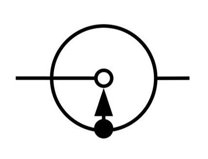
Governor symbol

Symbol of Speed governor

What are the two main components of a governor system?

Types of Governor

The Governor categorized in two types.

  • Centrifugal Governor
  • Inertia Governor

Centrifugal Governor

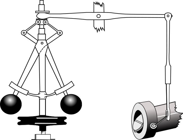
Centrifugal governor consists of a pair of governor balls attached to the arms, which are supported by the spindles as shown in the figure. This whole system is mounted on the shaft; this shaft is linked to the engine of the shaft thru a bevel gear mechanism. Under this assembly, a free to slide sleeve is attached to the shaft. A bell crank lever is connected to the sleeve. This lever connects the throttle valve and sleeve.

The activity of the governor be subject to the speed variation. The variations in the bell crank lever give the motion to the sleeve and eventually to the spindle and ball. The governor’s action is produced by the centrifugal effect of the masses of the balls.

When the speed of the engine increase, the balls intend to rotate with higher radius from the centered shaft position, this caused the sleeve to slide in the upward way on the spindle and these variations of the spindle will result in the closing action of the throttle-valve up to the mandatory limit thru the bell-crank lever mechanism. When the speed declines, the balls will rotate at a lesser radius, so the throttle valve opens accordingly.

It is a more common type of governor.

Type of Centrifugal Governors

The centrifugal governor is further classified as follows:

Capture

Inertia Governor

Inertia governor is based on the ‘Principle of Inertia of Matter’.

For Inertia Governor, more force acts with the centrifugal forces on the balls, whose position are decided by the angular acceleration and de-acceleration of the spindle in addition to the centrifugal force acts on the ball.

In the inertia type of governor, appropriate linkages and spring used for opening and closing the throttle valve according to the changes in the position of the ball.

In an inertia governor, when the acceleration or deceleration of an engine is very low, the additional inertia force practically becomes zero. In that case, the inertia governor becomes a centrifugal governor.

The inertia governor’s response is faster than that of the centrifugal governor.

Engine Governor

The throttle valve of an engine is operated by the governor called engine governor using a mechanism explained earlier.

Sensitiveness of a Governor

The movement of the sleeve essential for the minimal change in the speed of an engine is the measure of sensitiveness of a governor.

A governor’s sensitiveness is described as the ratio of the change in-between the highest and least speed to the mean equilibrium speed.

Thus,

Sensitiveness=frac{range of speed}{mean speed} =frac{N2-N1}{N} =frac{2(N2-N1)}{N}

Where,

N=mean speed

N1=minimum speed corresponding to full load conditions

N2=maximum speed corresponding to no-load conditions

Turbine Governor

A turbine governor is a component of a turbine control system that controls rotational speeds according to loading conditions.

A turbine governor provides on-line and start-up control for the generator, which drives the turbine.

Steam Turbine Governing

In a steam turbine, there is an inconsistent flow of steam. A steam turbine governing is a procedure of maintaining a constant rotation speed by controlling the steam turbine’s flow rate to the steam turbine.

Elevator Governor | Over-speed Governor

When the speed of an elevator crosses predetermined speed limits, a mechanism acts to control the system known as over speed governor.

A speed governor located in the elevator is a component of the safety system of the governor.

The position of the speed governor in the elevator is determined by the However, in many cases, it is installed in the machine room of the elevator.

Air Vane Governor

An air vane governor is a pneumatic type of governor.

In this system, airflow is used to regulate the throttle opening. This air vane of the governor is made up of plastic or metal. This governor also consists of the flywheel.

Speed Limiter for Car

A speed governor is used as a speed limiter for cars’ engines. It regulates the fuel supply of the car with varying load.

There are three types of the governor which are being used in automobiles:

·       Mechanical Governor

·       Hydraulic Governor

·       Pneumatic Governor


Woodward Governor

Wood ward governor is a well-known manufacturing company of governors.

Governor Switch | Governor Gear

Governor Switch, Governor Gear are parts of an evolved form of a speed governor.

Question and Answers related to Governor

What are the two main components of a governor system? 

The two main components of a governor are mechanical arrangement and hydraulic unit.

How does a mechanical governor work?

Centrifugal governor consists of a pair of governor balls attached to the arms, which are supported by the spindles as shown in the figure. This whole assembly is mounted on the shaft; this shaft is connected to the engine of the shaft using bevel gear. Under this assembly, a free to slide sleeve is attached to the shaft via a bell-cranks. This lever connects the throttle valve and sleeve.

As we already know, governor’s action is dependent on the speed variations. The changes in the bell crank lever give the motion to the sleeve and ultimately to the spindle and balls. The governor’s action is produced by the centrifugal effect of the masses of the balls.

During the engine’s speed increment, the ball will intend to rotate at a higher- radii from shaft’s position and caused the sleeve to sliding in the upward direction and this movement of the spindle consequences in the closing of the throttle-valves and if speed declines, these balls will rotate with less radii, so the throttle valve controlled accordingly.

What are the three types of governors?

There are three types of the governor which are being used in automobiles:

  • Mechanical Governor
  • Hydraulic Governor
  • Pneumatic Governor

What is Governor Sensitivity?     

Governor sensitivity is known as the sensitiveness of a governor.

The movement of the sleeve for the minimal change in the speed of an engine is the measure of sensitiveness of a governor.

Sensitiveness=frac{range of speed}{mean speed} =frac{N2-N1}{N} =frac{2(N2-N1)}{N}

Where,

N=mean speed

N1=minimum speed corresponding to full load conditions

N2=maximum speed corresponding to no-load condition

Which governor is more sensitive?     

Proell governor is known as the most sensitive governor in the centrifugal type of governors.

Whereas Porter governor is more sensitive than Watt governor.

What are the applications of a governor?

  1. A speed governor is used as a speed limiter for cars’ engines. It regulates the fuel supply of the car with varying load.
  2. A governor is used in elevators. When the speed of an elevator crosses predetermined speed limits, a mechanism acts to control the system known as over speed governor.
  3. A speed governor is used in different types of turbines. A turbine governor provides on-line and start-up control for the generator, which drives the turbine.

Which governor is used in cars? | What is a governor in a car?

A speed governor is used as a speed limiter for the engines of cars. It regulates the fuel supply of the car with varying load.

There are three types of the governor which are being used in automobiles:

  1. Mechanical Governor
  2. Hydraulic Governor
  3. Pneumatic Governor

What is the range of governor?

The variance between the maximum and minimum speed of a governor is known as a governor’s range.

What is the meaning of speed governor?

Whenever there is a variation in the load on the engine, there is a variation in the speed of an engine and to maintain the engine’s speed at stated limit, a speed governor is employed.

Can you remove a speed governor?

Yes. A speed governor is inbuilt for a car from the company, but it can be removed if we want.

Is speed governor compulsory?

Yes. It has been made compulsory in many countries to have a speed governor.

How does a speed governor work?

The throttle valve of an engine is operated by the governor, when the load on the engine shaft increases, it’s speed will decline except the fuel supply is increased by the throttle valve opening. Similarly, if the load on the engine shaft declines, its speed will increase unless the fuel supply is reduced by closing the throttle-valve appropriately to slowdown engine’s to actual speed.

What is a Hartnell governor?

A Hartnell governor is a centrifugal type of governor in which it is loaded with a spring.  Additional spring is used to apply an extra force to the spring.

Where is Hartnell governor used?      

A Hartnell governor is used in regulating the speed of the engine.

Which lever is used in Hartnell governor?  

The lever used in Hartnell governor is a bell crank lever.

What are the types of speed governor?

Governors are broadly classified into two types.

  1. Centrifugal Governor.
  2. Inertia Governor.

For more mechanical related articles click here

    Prandtl Number: 21 Important Facts

    image 14 300x58 1

    Content: Prandtl Number

    Prandtl Number

    “The Prandtl number (Pr) or Prandtl group is a dimensionless number, named after the German physicist Ludwig Prandtl, defined as the ratio of momentum diffusivity to thermal diffusivity.”

    Prandtl Number formula

    The Prandtl (Pr) number formula is given by

    Pr = Momentum diffusitivity/Thermal diffusitivity

    Pr = μCp/k

    Pr = ν/∝

    Where:

    μ = dynamic viscosity

    Cp = Specific Heat of the fluid taken into consideration

    k = Thermal Conductivity of the fluid

    ν = Kinematic viscosity

    α = Thermal diffusivity

    ρ = Density of the fluid

    Prandtl (Pr) number is independent of Length. It depends upon the property, Type and state of the fluid. It gives the relation between the viscosity and thermal conductivity.

    Fluids having Prandtl (Pr) number in the Lower spectrum are free-flowing fluids and generally possess high thermal conductivity. They are excellent as heat conducting liquids in heat exchanger and similar applications. Liquid metals are brilliant in heat transfer.  As viscosity increases Prandtl (Pr) number increases and thus heat conduction capacity of fluid decreases.

    Physical significance of Prandtl Number

    During heat-transfer in-between wall and a flowing-fluid, heat is transferred from a high-temperature wall to the flowing fluid thru a momentum boundary-layer that comprises the bulk-fluid substance and a transitional and a thermal boundary-layer that comprises of stationary film. In the stagnant film, heat transfer occurs by conduction in the fluid. The importance of Prandtl (Pr) number of the flowing fluid is to taken into account as it relates momentum boundary-layer to the thermal one during heat-transfer through the fluid.

    when Prandtl (Pr) number has Small values, Pr << 1, It represents that thermal diffusivity dominating over momentum diffusivity and liquid metal has lower Prandtl (Pr) number and heat diffuses significantly faster in that. Thermal boundary layer has higher thickness comparation of velocity-based boundary-layer in liquid-metal.

    Similarly, for large values of Prandtl (Pr) number, Pr >> 1, the momentum diffusivity dominates over thermal diffusivity. oils have higher Prandtl (Pr) number and heat diffuses slowly in oils. Thermal boundary layer has Lower thickness relative to velocity boundary layer in oils.

    For liquid mercury the heat conduction is more dominant in comparison to convection, Thus thermal diffusivity is dominant in Mercury. Though, for engine-oil, convection is highly effective in heat transfer from a high temperature area when compared to purely conduction case, thus, momentum diffusivity is significant parameter in Engine-oil.

    Gases lie in the middle of this spectrum. Their Prandtl (Pr) number is about 1. Thermal boundary layer has equal thickness relative to velocity boundary layer.

    The ratio of the thermal to momentum boundary layer over a flat plate is given by the following equation

    δt/δ = Pr-1/3 0.6<Pr<50

    Magnetic Prandtl Number

    Magnetic Prandtl Number is a dimensionless number which gives the relation between Momentum diffusivity and magnetic diffusivity. It is the ratio of viscous diffusion rate to the magnetic diffusion rate. It generally occurs in magnetohydrodynamics. It can also be evaluated as the ratio of magnetic Reynold’s Number to the Reynold’s Numbers.

    Prm = ν/η

    Prm = Rem/Re

    Where,

    Rem is the magnetic Reynolds number

    Re is the Reynolds number

    ν is the viscous diffusion rate

    η is the magnetic diffusion rate

    Prandtl Number Heat Transfer

    when Prandtl (Pr) number has Small values, Pr << 1, It represents that thermal diffusivity dominating over momentum diffusivity. Liquid metal has lower Prandtl (Pr) number and heat disseminates very quickly in Liquid metal and Thermal-boundary layer is much thicker in comparison to velocity-boundary layer in liquid-metal.

    Similarly, for large values of Prandtl (Pr) number, Pr >> 1, the momentum diffusivity dominates over thermal diffusivity. oils have higher Prandtl (Pr) number and heat diffuses slowly in oils. Thermal boundary layer has Lower thickness relative to velocity boundary layer in oils.

    For  liquid mercury the heat conduction is more dominant in comparison to convection, Thus thermal diffusivity is dominant in Mercury. Though, for engine’s oil, convection is highly effective in heat-transfer from a high temperature area when compared to purely conductive, thus, momentum diffusivity is significant in Engine’s oil.

    Gases lie in the middle of this spectrum. Their Prandtl (Pr) number is about 1. Thermal boundary layer has equal thickness relative to velocity boundary layer.

    The ratio of the thermal to momentum boundary layer over a flat plate is given by the equation

    δt/δ = Pr-1/3 0.6<Pr<50

    Turbulent Prandtl Number

    The turbulent Prandtl number Prt is a dimensionless term. It is the ratio of momentum eddy diffusivity to the heat transfer eddy diffusivity and utilized for the evaluation of heat transfer for turbulent boundary layer flow condition.

    Does heat transfer coefficient depend on Prandtl number?

    Heat Transfer coefficient is also calculated by means of Nusselt’s Number. This is represented by the ratio of Convective heat transfer to the conductive heat transfer.

    For forced convection,

    Nμ = hLc/K

    Where, 

    h = the convective heat transfer coefficient

    Lc = the characteristic length,

    k = the thermal conductivity of the fluid.

    Also, Nusselt Number is the function of Reynold’s Number and Prandtl (Pr) number. Thus, Change in Prandtl (Pr) number changes the Nusselt Number and thus heat transfer coefficient.

    Does Prandtl number change with pressure?

    Prandtl (Pr) number is assumed to be independent of pressure. Prandtl (Pr) number is a function of Temperature since μ,Cp are the function of Temperature but a very weak function of pressure.

    Effect of Prandtl number on boundary layer | Effect of Prandtl number on heat transfer

    when Prandtl (Pr) number has Small values, Pr << 1, It represents that thermal diffusivity dominating over momentum diffusivity. Liquid metals have lower Prandtl (Pr) number and heat diffuses very quickly in Liquid metals. Thermal boundary layer has higher thickness relative to velocity boundary layer in Liquid metals.

    Similarly, for large values of Prandtl (Pr) number, Pr >> 1, the momentum diffusivity dominates over thermal diffusivity. oils have higher Prandtl (Pr) number and heat diffuses slowly in oils. Thermal boundary layer has Lower thickness relative to velocity boundary layer in oils.

    For  liquid mercury the heat conduction is more dominant in comparison to convection, Thus thermal diffusivity is dominant in Mercury.

    Gases lie in the middle of this spectrum. Their Prandtl (Pr) number is about 1. Thermal boundary layer has equal thickness relative to velocity boundary layer.

    Prandtl number of Air

    Prandtl (Pr) number for Air is given below in the table

    Prandtl (Pr) number of Air at 1 atm pressure, temperature °C is given as:

    TemperaturePr
    [°C]Dimensionless
    -1000.734
    -500.720
    00.711
    250.707
    500.705
    1000.701
    1500.699
    2000.698
    2500.699
    3000.702
    Pr number of Air at 1 atm pressure

    Prandtl number of Water at different Temperatures

    Prandtl (Pr) number of Water in Liquid and vapor form at 1 atm Pressure is shown below:

    TemperaturePr number
    [°C]Dimensionless
    013.6
    511.2
    109.46
    206.99
    256.13
    305.43
    503.56
    752.39
    1001.76
    1001.03
    1250.996
    1500.978
    1750.965
    2000.958
    2500.947
    3000.939
    3500.932
    4000.926
    5000.916
    Pr number of Water in Liquid and vapor form

    Prandtl number of Ethylene glycol

    Prandtl (Pr) number of Ethylene glycol is Pr = 40.36.

    Prandtl number of Oil | Prandtl number of Engine Oil

    Prandtl (Pr) number for oil lies between the range of 50-100,000

    Prandtl (Pr) number of Engine Oil at 1 atm Pressure are given below:

    Prandtl number Table

    Temperature (K)Pr number
    260144500
    28027200
    3006450
    3201990
    340795
    360395
    380230
    400155
    Pr number of Engine Oil

    Prandtl number of Hydrogen

    Prandtl (Pr) number of Hydrogen at 1 atm Pressure and at 300 K is 0.701

    Prandtl number of Gases | Prandtl Number of Argon, Krypton etc.

    Prandtl Number of Gases

    Prandtl number of Liquid Metals and other Liquids

    Prandtl number of Liquid Metals

    Benzene Prandtl number

    Prandtl (Pr) number of Benzene at 300 K is 7.79.

    CO2 Prandtl number

    Prandtl (Pr) number of Hydrogen at 1 atm Pressure is 0.75

    Prandtl number of Ethane

    Prandtl (Pr) number of Ethane is 4.60 in Liquid form and 4.05 in gaseous form

    Gasoline Prandtl number

    Prandtl (Pr) number of Gasoline is 4.3

    Glycerin Prandtl number

    Prandtl (Pr) number of Glycerin lies between the range of 2000-100,000

    Some Important FAQs

    Q.1 How is Prandtl number calculated?

    Ans:  Pr Number can be calculated by using the formula

    Pr = μCp/K

    Where:

    • μ = dynamic viscosity
    • Cp = Specific Heat of the fluid taken into consideration
    • k = Thermal Conductivity of the fluid

    Q.2 What is the value of Prandtl number for liquid metals?

    Ans: The Prandtl (Pr) number for Liquid metals is extremely Low. Pr<<<1. For example In liquid mercury has Prandtl (Pr) number = 0.03 which represents that, the heat conduction is more dominant in comparison to convection, Thus thermal diffusivity is dominant in Mercury.

    Q.3 What is the Prandtl number of Water?

    Ans: Prandtl (Pr) number of Water in Liquid and vapor form at 1 atm Pressure is shown below:

    TemperaturePrandtl (Pr) number
    [°C]Dimensionless
    013.6
    511.2
    109.46
    206.99
    256.13
    305.43
    503.56
    752.39
    1001.76
    1001.03
    1250.996
    1500.978
    1750.965
    2000.958
    2500.947
    3000.939
    3500.932
    4000.926
    5000.916
    Prandtl (Pr) number of Water in Liquid and vapor form

    Q.4 What does Prandtl number represent?

    Ans: During the heat transfer amongst a wall-barrier and fluid, heat is transferred from a high-temp barrier to fluid through a momentum-boundary-layer. This includes fluids and a transitional and a thermal boundary-layer that comprises of film. In the stagnant film, heat transfer happens by fluid’s conduction on that time. The Pr number of the flowing fluid, is ratio which taken into account of momentum boundary layer to the thermal boundary layer.

    Q.5 what is the Prandtl Number for Steam?

    Ans: The Prandtl (Pr) number for steam at 500 C is 0.916.

    Q.6 what is the Prandtl Number for Helium?

    Ans: Prandtl (Pr) number of Helium is 0.71

    Q.7 what is the Prandtl Number for Oxygen?

    Ans: Prandtl (Pr) number of Oxygen is 0.70

    Q.8 What is the Prandtl Number for Sodium?

    Ans: Prandtl (Pr) number of Sodium is 0.01

    Q.9 How is the Prandtl number related with kinematic viscosity and thermal diffusivity?

    Ans: The Prandtl (Pr) number is well-defined as the ratio of momentum diffusivity to thermal diffusivity.

    Its formula is given by:

    The Pr Number formula is given by

    Pr = Momentum diffusivity/ Thermal diffusivity

    Pr = μCp/K

    Pr = μ

    Where:

    μ = dynamic viscosity

    Cp = Specific Heat of the fluid taken into consideration

    k = Thermal Conductivity of the fluid

    ν = Kinematic viscosity

    ν = μ/ρ

    α = Thermal diffusivity

    α = K/ρCp

    ρ = Density of the fluid

    From the above formula we can say that Prandtl (Pr) Number is inversely proportional to Thermal diffusivity and directly proportional to Kinematic viscosity.

    Q.10 Is there any fluid which has a Prandtl number in the range of 10 20 except water?

    Ans: There are certain number of fluids that has Prandtl (Pr) Number in the range of 10-20. They are Listed below:

    1. Acetic acid [Pr = 14.5] at 15C and [Pr = 10.5] at 100C
    2. Water [Pr = 13.6] at 0C
    3. n-Butyl Alcohol is [Pr = 11.5] at 100 C
    4. Ethanol [Pr = 15.5] at 15C and [Pr = 10.1] at 100C
    5. Nitro Benzene [Pr = 19.5] at 15C
    6. Sulfuric acid at high concentration about 98% [Pr = 15] at 100C

    To know about Simply Supported Beam (click here)and Cantilever beam (Click here)

    Hooke’s Law: 10 Important Facts

    stress strain hooks 290x300 1

    What is Hooke’s Law?

    Hooke’s law basic properties:

    The mechanical behaviour of materials depends on their response to loads, temperature, and the environment. In several practical problems, these controlling parameters’ combined effects must be assessed. However, the individual effects of loads (elastic and plastic deformation) must be studied in detail before attempting to develop an understanding of the combined effects of load and temperature or the effects of load and environment. The material response may also depend on the nature of the loading. When the applied deformation increases continuously with time (as in a tensile test), then reversible (elastic) deformation may occur at small loads before the onset of irreversible/plastic deformation at higher loads. Under reversed loading, the material may also undergo a phenomenon known as ”fatigue.”

    Hooke’s Law Definition:

    Robert Hooke law 1660. It states that the material’s deformations are directly proportional to the externally applied load on the material. 

    According to Hooke’s law, the material behavior elastic can be explained as the displacements occurring in the solid material due to some force. The displacement is directly proportional to the force applied.

    Does Hooke’s law include proportional limits or elastic limits?

    Hooke’s law tell strain of the material is proportionate to the stress applied within the elastic limit of that material.

    Stress-strain curve for Hooke’s law:

    Stress :

    The resistance offered by the body against deformation to the applied external force to the unit area is known as stress. The force is applied while stress is induced by the material. A loaded member remains in equilibrium when the externally applied load and the force due to deformation are equal.

    \\sigma =\\frac{P}{A}

    Where,

    \\sigma= Intensity of stress,

    • P= Externally applied load
    • A= cross-sectional area

    Unit of Stress:

    The unit stress depends on the unit of External force and the cross-sectional area.

    Force is expressed in Newton, and Area is expressed in m^2.

    The unit of stress is N/m^2.

    Types of stress:

    Tensile stress:

    The stress induced in the body due to the stretching of the externally applied load on the material.Results in an increase in the length of the material.

    Compressive stress:

    The stress induced in the body due to the shortening of the material.

    Shear stress:

    The stress occurred in the material due to the shearing action of external force.

    Strain:         

    When the body is subjected to external force, there is some change in the dimension of the body.

    The strain is represented as the ratio of the change in dimension of the body to that of the original dimension of the body.

    \\varepsilon =\\frac{\\Delta L}{L}

    Unit of Strain

    The strain is a dimensionless quantity.

    Types of strain:

    Tensile strain: 

    The tensile strain is the strain induced due to the change in length.

    Volumetric strain:

    The volumetric strain is the strain induced due to the change in volume.

    Shear strain:

    The shear strain is the strain induced due to change in the area of the body.

    Hooke’s law graph | Hooke’s law experiment graph

    Hooke's Law: Stress-strain curve
    Image credit:[User:Slashme] (David Richfield), Stress v strain A36 2, CC BY-SA 3.0

    Robert Hooke studied springs and the elasticity of the springs and discovered them. The stress-strain curve for various materials has a linear region. Within the proportionality limit, the force applied to pull any elastic object is directly proportional to the displacement of the spring extension.

    From the origin to proportionality limit material follows Hook’s Law. Beyond the elastic limit, the material loses its elasticity and behaves like plastic. When the material undergoes elastic limit, After removal of the applied force, the material goes back to its original position.

    According to Hookes law stress is directly proportional to strain up to elastic limit but that stress vs strain curve is linear up to proportional limit rather than elastic limit Why ?

    Which of these statements is correct All elastic materials follow Hookes law or materials that follow Hookes law are elastic ?

    • Answer:

    All elastic materials does not follow Hook’s law. There are some elastic materials that does does not obey Hook’s law. so the first statement is invalid. But it is not necessity that materials that follow Hook’s law are elastic, In stress-strain curve for Hook’s law materials follow Hook’s law till their proportional limit and do possess elasticity. Every material has some elastic nature at certain limit and it can store elastic energy at certain point.

    What is the difference between Hookes law and Youngs modulus ?

    Hooke’s law of Elasticity :

    When an external force is applied to the body, the body tends to deform. If the external force is removed and the body comes back to its original position. The tendency of the body to coming back to its original position after the removal of stress is known as elasticity. The body will regain its original position after the removal of stress within a certain limit. Thus there is a limiting value of force up to which and within which the deformation disappears completely. The stress that corresponds to this limiting force is an elastic limit of the material.

    Young’s modulus | Modulus of Elasticity:

    The proportionality constant between the stress and strain is known as young’s modulus and modulus of elasticity.

     \\sigma =E\\varepsilon

    E= Young’s Modulus

    What is an example of Hooke’s law ?

    Hooke’s law spring:

    An important component of automobile objects , the spring stores potential elastic energy when it is stretched or compacted. The spring extension is directly proportional to the applied force within the proportionality limit.

    Mathematical representation of the Hooke’s law states that the applied force is equal to the K times the displacement,

    F= -Kx

    Hook’s law material elastic properties can only be explained when applied force is directly proportional to the displacement.

    What is the name of the substance that does not obey Hooke’s law ?

    Answer : Rubber

    Does Hooke’s law fails in case of thermal expansion?

    Answer : No

    Hooke’s law stress strain | Hooke’s law for plane strain

    Hooke’s law is important to understand the behaviour of the material when it is stretched or compressed. It is important to enhance the technology by understanding the material behaviour properties.

    Hooke’s law equation stress strain

    F=ma

    σ=F/A

    ε = Δl/l0

    σ = E ε

    F= -k * Δx

    Strain is the ratio of total deformation or change in length to the initial length.

    This relationship is given by ε = Δl/l0 where strain, ε, is change in l divided by initial length , l0 .

    Why do we consider a spring massless in Hooke’s law ?

    Hooke’s law is dependent on the spring extension and spring constant and is independent on the mass of the spring.so we consider spring massless in Hook’s law.

    Hooke’s law experiment :

    The Hooke’s law experiment performed to find out the spring constant of the spring. The original length of the spring before applying load is measured. Record the applied loads (F) in N and the corresponding lengths of the spring after extension. The deformation is the new length minus the original length before loads.

    Since the force has the form

     F = -kx

    Why is Hooke’s law negative ?

    While representing hooks law for springs, the negative sign is always presented before the product of the spring constant and the deformation even though the force is not applied. The restoring force, which gives the deformation to the spring and the spring, is already in the opposite direction to that of the applied force. Thus, it is important to mention the direction of the restoring force while solving elastic material problems.

    Derivation of Hooke’s Law:

    Hooke’s Law equation:

    F=-kx

    Where,

    • F=Applied force
    • k=Constant for displacement
    • x = Length of the object
    • The use of k is dependent on the kind of elastic material, its dimensions and its shape.
    • When we apply a relatively large amount of applied force, the material deformation is larger.
    • Although, the material remains elastic as before and returns to its original size, and when we remove the force that we apply, it retains its shape. At times,

    Hooke’s law describes the force of

    F = -Kx

    Here, F represents the equal and oppositely applied to restore, causing the elastic materials to get back to their original dimensions.

    How is Hooke’s Law measured?

    Hooke’s law units

    SI units: N/m or kg/s2.

    Hooke’s law spring constant

    We can easily understand Hooke’s Law in connection with the spring constant. Moreover, this law states that the force required for compression or extension of a spring is directly proportional to the distance to which we compress or stretch it.

    In mathematical terms, we can state this as follows:

    F=-Kx

    Here,

    F represents the force that we apply in the spring. And x represents the compression or extension of the spring, which we usually expressed in metres.

    Hooke’s law example problems

    Let us understand this more clearly with the following example:

    It stretches a spring by 50 cm when it has a load of 10 Kg. Find its spring constant.

    Here, it has the following information:

    Mass (m) = 10 Kg

    Displacement (x) = 50cm = 0.5m

    Now, we know that,

    Force= mass x acceleration

    => 10 x 0.5= 5 N.

    As per the Spring Constant formula

    k = F/x

    => -5/0.5= -10 N/m.

    Applications of Hooke’s law | Hooke’s law application in real life

    1. It is used in Engineering applications and physics.
    2. Guitar string
    3. Manometer
    4. spring scale
    5. Bourdon tube
    6. Balance wheel

    Hooke’s law experiment discussion and conclusion

    Limitation of Hooke’s law:

    Hooke’s law is a first-order approximation to the response of the elastic bodies. It will eventually fail once the material undergoes compression or tension beyond its certain elastic limit without some permanent deformation or change of state. Many materials vary well before reaching the elastic limits.

    Hook’s law is not a universal principle. It does not apply to all the materials. It applies to the materials having elasticity. And till the material capacity to stretch to a certain point from where they won’t regain their original position.

    It is applicable until the elastic limit of the material. If the material is stretched beyond the elastic limit, plastic deformation takes place in the material.

    The law can give exact answers only to the material undergoing small deformations and forces.

    Hooke’s law and elastic energy:

    Elastic Energy is the elastic potential energy due to the stored deformation of the stretching and compression of an elastic object, such as stretching and release of the spring. According to Hook’s law, the force required is directly proportional to the amount of stretch of the spring.

    Hook’s Law: F= -Kx             — (Eq1)

    The force applied is directly proportional to the extension and deformation of the elastic material. Thus,

    Stress is directly proportional to strain as stress is the applied force to that of unit area and strain is deformation to that of the original dimension. The stress and strain considered are normal stress and normal strain.

    In shearing stress,Material must be homogeneous and isotropic within its certain proportionality limits.

    Shear stress represented as,

    τxy = Gγxy —(Eq2)

    Where,

    • τxy=shear stress
    • G=modulus of rigidity
    • γxy=shearing strain

    This relation represents Hook’s law for shear stress. It is considered for the small amount of force and deformation. Material leads to failure if applied load larger force.

    Considering material subjected to shearing stresses τyz and τzy, for small stress, the γxy will be the same for both the conditions and are represented in similar ways. The shear stresses within the proportional limit,

    τxy = Gγxy —(Eqn3)

    τxy = Gγxy —(Eqn4)

    Case1: plain strain  where the strains in the z-direction are considered to be negligible,

    \\varepsilon zz=\\varepsilon yz=\\varepsilon xz=0

    the stress-strain stiffness relationship for isotropic and homogeneous material represented as,

    1

    The stiffness matrix reduces to a simple 3×3 matrix, The compliance matrix for the plane strain is found by inverting the plane strain stiffness matrix and is given by,

    2

     Case2:Plane strain:

    The stress-strain stiffness matrix expressed using the shear modulus G, and the engineering shear strain

    \\gamma xy=\\varepsilon xy+\\varepsilon yx=2\\varepsilon xy is represented as,

    4

    The compliance matrix is,

    5

    Hooke’s law Problems:

    States Hookes Law What is the spring constant of a spring that needs a force of 3 N to be compressed from 40 cm to 35 cm.

    Hook’s law:

    F= -Kx ,

    3= -K (35-40)

    K=0.6

    A force of 1 N will stretch a rubber band by 2 cm Assuming that Hookes law applies how far will a 5 N force stretch the rubber band

    Force is directly proportional to the amount of the stretch, According to Hook’s law:

    F= -Kx

    \\frac{F1}{F2}=\\frac{x1}{x2}

      F2=3cm

    For more article click here

    Reynolds Number: 21 Important Facts

    Reynolds Number

    Content

    Reynolds number definition

    “The Reynolds number is the ratio of inertial forces to viscous forces.”

    The Reynolds number is a dimensionless number used to study the fluid systems in various ways like the flow pattern of a fluid, the flow’s nature, and various fluid mechanics parameters. The Reynold’s number is also important in the study of heat transfer. There are much correlation developed, including Reynold’s number in fluid mechanics, tribology and heat transfer. The preparation of various medicines in pharmacy required Reynold’s number study.

    It is actually a representation and comparison of inertia force and viscous force.

    Reynolds number equation

    The dimensionless Reynold’s number represents whether the flowing fluid would be laminar flow or turbulent flow, considering to some properties such as velocity, length, viscosity, and flow type. The Reynold’s number has been discussed as follow:

    The Reynold’s number is generally termed as the inertia force ratio to viscous force and characterize the flow nature like laminar, turbulent etc. Let’s see by the equation as below,

    Re= \\frac{Inertia force}{viscous force}

    Inertia force =\\rho A V^{2}

    Viscous force = \\frac{\\mu V A}{D}

    By putting the inertia force and viscous force expression in Reynold’s number expression, we get

    Re = \\frac{\\\\rho V D}{\\mu }

    In above equation,

    Re = Reynold’s number (Dimensionless number)

    ? = density of fluid (kg / m3)

    V = velocity of flow ( m/ s )

    D = Diameter of flow or pipe/ Characteristics length ( m )

    μ = Viscosity of fluid (N *s /m2)

    Reynolds number units

    The Reynold’s number is dimensionless. There is no unit of Reynolds number.

    Reynolds number for laminar flow

    The identification of flow can be possible by knowing the Reynold’s number. The Reynold’s number of laminar flow is less than 2000. In an experiment, if you get a value of Reynold’s number less than 2000, then you can say that the flow is laminar.

    Reynolds number of water

    The equation of Reynold’s number is given as

    Reynolds number= \\frac{Density of fluid \\cdot velocity of flow\\cdot Diameter of flow/Length}{Viscosity of fluid}

    If we analyze the above equation, the Reynolds number’s value depends on the density of fluid, velocity of flow, the diameter of flow directly and inversely with the viscosity of the fluid. If the fluid is water, then the density and viscosity of water are the parameters that directly depend on water.

    laminar to turbulent convertion
    laminar to turbulent
    Image credit : brewbooks from near Seattle, USA, Laminar to Turbulent – Flickr – brewbooksCC BY-SA 2.0

    Reynolds number for turbulent flow

    Generally, the Reynolds number experiment can predict the flow pattern. If the value of Reynold’s number is >  4000, then the flow is considered as turbulent nature.

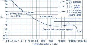
    Drag Coefficient (Cd) vs Reynolds number (Re) in various objects

    Renolds Number
    Image credit : “File:Drag Coefficient (Cd) vs Reynolds number (Re) in various objects.png” by Welty, Wicks, Wilson, Rorrer. is licensed under CC BY-SA 4.0

    Reynolds number in a pipe

    If the fluid is flowing through the pipe, we want to calculate Reynold’s number of fluid flowing through a pipe. The other all parameters depends on the type of fluid, but the diameter is taken as pipe Hydraulics diameter  DH (For this, the flow should be properly coming out from the pipe)

    Reynolds number= \\frac{Density of fluid \\cdot velocity of flow\\cdot Hydraulic Diameter of flow/Length}{Viscosity of fluid}

    Reynolds number of air

    As we have discussed in Reynold number for water, The Reynold number for air directly depends on air density and viscosity.

    Reynolds number range

    Reynold’s number is the criteria to know whether the flow is turbulent or laminar.

    If we consider the flow is internal then,

    If Re < (2000 to 2300) flow is considered laminar characteristics,

     Re > 4000 represents turbulent flow

    If Re’s value is in between (i.e. 2000 to 4000)  represents transition flow.

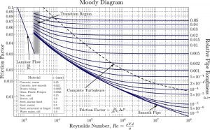
    Reynolds number chart

    The moody chart is plotted between Reynolds number and friction factor for different roughness.

    We can find the Darcy-Weisbach friction factor with Reynold number. There is an analytical correlation developed to find the friction factor.

    Reynolds number
    Reynold’s number in Moody Diagram Wikipedia
    Credit Original diagram: S Beck and R Collins, University of Sheffield (Donebythesecondlaw at English Wikipedia) Conversion to SVG: Marc.derumauxMoody ENCC BY-SA 4.0

    Reynolds number kinematic viscosity

    The kinematic viscosity is given as,

    Kinematic viscosity = \\frac{Viscosity of fluid}{Density of fluid}

    The Equation of Reynold’s number,

    Reynolds number= \\frac{Density of fluid \\cdot velocity of flow\\cdot Hydraulic Diameter of flow/Length}{Viscosity of fluid}

    The above equation is formed as below if write it in the form of kinematic viscosity,

    [Reynolds number= \\frac{velocity of flow\\cdot Hydraulic Diameter of flow/Length}{Kinematic Viscosity of fluid}

    Re =\\frac{VD}{\ u }

    Reynolds number cylinder

    If the fluid is flowing through the cylinder and we want to calculate Reynold number of fluid flowing through the cylinder. The other all parameters depends on the type of fluid, but the diameter is taken as Hydraulics diameter DH (For this, the flow should be properly coming out from the cylinder)

    Reynolds number mass flow rate

    We then analyse the Reynold’s number equation if we want to see the relationship between the Reynold’s number and mass flow rate.

    Re = \\frac{\\rho V D}{\\mu }

    As we know from the continuity equation, the mass flow rate is expressed as below,

    m =\\rho \\cdot A\\cdot V

    By putting values of mass flow rate in the Reynolds number equation,

    Re =\\frac{m\\cdot D}{A\\cdot \\mu }

    It can be clearly noted from the above expression that the Reynold’s number has a direct relation with the mass flow rate.

    Laminar vs turbulent flow Reynolds number | Reynolds number laminar vs turbulent

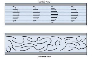
    Generally, in fluid mechanics, we are analyzing two types of flow. One is the laminar flow which occurs at low velocity, and another is the turbulent flow which generally occurs at high velocity.  Its name describes the laminar flow as the fluid particles flow in the lamina (linear) throughout the flow. In turbulent flow, the fluid travels with random movement throughout the flow.

    Let’s understand this important point in detail,

    Laminar and Turbulent
    Reynolds number for Laminar and Turbulent flow
    Image credit :JoseasorrentinoTransicion laminar a turbulentoCC BY-SA 3.0

    Laminar Flow

    In laminar flow, the adjacent layers of fluid particles do not intersect with each other and flows in parallel directions is known as laminar flow.

    In the laminar flow, all fluid layers flow in a straight line.

    • There possibility of occurrence of laminar flow when the fluid flowing with low velocity and the diameter of the pipe is small.
    • The fluid flow with a Reynold’s number less than 2000 is considered laminar flow.
    • The fluid flow is very linear. There is the intersection of adjacent layers of the fluid, and they flow parallel to each other and with the surface of the pipe.
    • In laminar flow, the shear stress only depends on the fluid’s viscosity and independent of the density of the fluid.

    Turbulent Flow

    The turbulent flow is opposite to the laminar flow. Here, In fluid flow, the adjacent layers of the flowing fluid intersect each other and do not flow parallel to each other, known as turbulent flow.

    The adjacent fluid layers or fluid particles are not flowing in a straight line in a turbulent flow. They flow randomly in zigzag directions.

    • The turbulent flow is possible if the velocity of the flowing fluid is high, and the diameter of the pipe is larger.
    • The value of the Reynold’s number can identify the turbulent flow. If the  value of Reynold’s number is more than 4000, then the flow is considered a turbulent flow.
    • The flowing fluid does not flow unidirectional. There is a mixing or intersection of different fluid layers, and they do not flow in parallel directions to each other but intersecting each other.
    • The shear stress depends on its density in a turbulent flow.

    Reynolds number for flat plate

    If we analyse the flow over a flat plate, then the Reynolds number is calculated by the flat plate’s characteristics length.

    Re = \\frac{\\rho V L}{\\mu }

    In the above equation, Diameter D is replaced by L, which is the characteristics length of flow over a flat plate.

    Reynolds number vs drag coefficient

    Suppose the Reynold’s number’s value is lesser than the inertia force. There is a higher viscous force getting dominance on inertia force.

    If the fluid viscosity is higher, then the drag force is higher.

    Reynolds number of a sphere

    If you want to calculate it for this case, the formula is

    Re = \\frac{\\rho V D}{\\mu }

    Here, Diameter  D is taken as Hydraulics diameter of a sphere in calculations like cylinder and pipe.

    What is Reynolds number?

    Reynold’s number is the ratio of inertia force to viscous force. Re indicates it. It is a dimensionless number.

    Re= \\frac{Inertia force}{viscous force}

    Significance of Reynolds number | Physical significance of Reynolds number

    Reynold number is nothing but comparing of two forces. One is the inertia force, and the second is the viscous force. If we take both force ratio, it gives a dimensionless number known as Reynold number. This number helps to know flow characteristics and know which of the two forces impacts more on flow. The Reynold number is also important for flow pattern estimation.

       Viscous force -> Higher -> Laminar flow -> Flow of oil

       Inertia Force -> Higher -> Turbulent flow > Ocean waves

    Reynolds experiment

    Osborne Reynolds first performed the Reynolds experiment in 1883 and observe the water motion is laminar or turbulent in pattern.

    This experiment is very famous in fluid mechanics. This experiment is widely used to determine and observe the three flow. In this experiment, the water flows through a glass tube or transparent pipe.

    The dye is injected with water flow in a glass tube. You can notice the flow of dye inside the glass tube. If the dye has a different colour than water, it is clearly observable. If the dye is flowing inline or linear, then the flow is laminar. If it dye shows turbulence or not flowing in line, we can consider the turbulent flow. This experiment is simple and informative for students to learn about flow and Reynolds number.

    Critical Reynolds number

    The critical Reynolds number is the transition phase of laminar and turbulent flow region. When the flow is changing from laminar to turbulent, the Reynold’s number reading is considered a critical Reynold’s number. It is indicated as ReCr.  For every geometry, this critical Reynold’s number will be different.

    Conclusion

    Reynolds number is important terms in the field of engineering and science. It is used in study of flow, heat transfer, pharma etc. We have elaborated this topic in detail because of its importance. We have included some practical questions and answers with this topic.

    For more articles on the related topics click here , Please find below

    Polytropic Process : 11 Important Concepts

    image 13

    Definition Polytropic process

    “A polytropic process is a thermodynamic process that obeys the relation: PVn = C, where where p is the pressure, V is volume, n is the polytropic index, and C is a constant. The polytropic process equation can describe multiple expansion and compression processes which include heat transfer.”

    Polytropic Equation | Polytropic equation of state

    The polytropic process can be defined by the equation

    PV^n=C

    the exponent n is called polytropic index. It depends upon the material and varies from 1.0 to 1.4. This is constant specific heat procedure, in which heat absorption of gas taken into consideration because of unit rise in temperature is fixed.

    Polytropic process index

    Polytropic index

    Some important relations between Pressure [P], Volume [V] and temperature [T] in Polytropic process for an Ideal Gas

    Polytropic equation is,

    PV^n=C

    \\\\P_1V_1^n=P_2V_2^n\\\\ \\\\\\frac{P_2}{P_1}=[\\frac{V_1}{V_2}]^n

    ………………………. Relations between Pressure [P] and Volume [V]

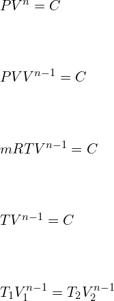
    \\\\PV^n=C\\\\ \\\\PVV^{n-1}=C\\\\ \\\\mRTV^{n-1}=C\\\\ \\\\TV^{n-1}=C\\\\ \\\\T_1 V_1^{n-1}=T_2 V_2^{n-1}

    \\frac{T_2}{T_1}=[\\frac{V_1}{V_2}]^{n-1}

    ………………………. Relations between Volume [V] and Temperature [T]

    \\frac{T_2}{T_1}=[\\frac{P_2}{P_1}]^\\frac{n-1}{n}

    ………………………. Relations between Pressure [P] and Temperature [T]

    Polytropic Work

    Ideal gas equation for polytropic process is given by

    \\\\W=\\int_{1}^{2}Pdv\\\\ \\\\W=\\int_{1}^{2}\\frac{C}{V^n}dv\\\\ \\\\W=C[\\frac{V^{-n+1}}{-n+1}]^2_1\\\\ \\\\W=\\frac{P_1V_1V_1^{-n+1}-P_2V_2V_2^{-n+1}}{n-1}\\\\ \\\\W=\\frac{P_1V_1-P_2V_2}{n-1}

    Polytropic Heat transfer

    According to 1st law of thermodynamics,

    dQ=dU+W

    \\\\dQ=mC_v [T_2-T_1 ]+\\frac{P_1 V_1-P_2 V_2}{n-1}\\\\ \\\\dQ=\\frac{mR}{\\gamma -1} [T_2-T_1 ]+\\frac{P_1 V_1-P_2 V_2}{n-1}\\\\ \\\\dQ=\\frac{P_1 V_1-P_2 V_2}{\\gamma-1}+\\frac{P_1 V_1-P_2 V_2}{n-1}\\\\ \\\\dQ=P_1 V_1 [\\frac{1}{n-1}-\\frac{1}{\\gamma-1}]-P_2 V_2 [\\frac{1}{n-1}-\\frac{1}{\\gamma-1}]\\\\ \\\\dQ=\\frac{\\gamma -n}{\\gamma -1}\\frac{P_1 V_1-P_2 V_2}{n-1}\\\\ \\\\dQ=\\frac{\\gamma -n}{\\gamma -1}W_{poly}

    Polytropic vs isentropic process

    Polytropic process is a thermodynamic process which follows the equation

    PVn = C

    This process takes into consideration the frictional losses and irreversibility factor of a process. It is a real-life actual process followed by the gas under specific conditions.

    Isentropic Process also known as reversible Adiabatic process is an ideal process in which no energy transfer or heat transfer takes place across the boundaries of the system. In this process system is assumed to have an insulated boundary. Since Heat transfer is zero. dQ = 0

    According to first law of thermodynamics,

    \\Delta U=-W=\\int Pdv

    Polytropic process vs adiabatic process

    Polytropic process is a thermodynamic process which follows the equation

    PVn = C

    This process takes into consideration the frictional losses and irreversibility factor of a process. It is a real-life actual process followed by the gas under specific conditions.

    Adiabatic process is a special and specific condition of polytropic process in which  .

    Similar to Isentropic process in this process too, no energy transfer or heat transfer takes place across the boundaries of the system. In this process system is assumed to have an insulated boundary.

    Polytropic efficiency

    “Polytropic Efficiency well-defined as the ratio of Ideal work of compression for a differential pressure change in a multi-stage Compressor, to the Actual work of compression for a differential pressure change in a multi-stage Compressor.”

    In simple terms it is an isentropic efficiency of the process for an infinitesimally small stage in a multi-stage compressor.

    \\eta_p=\\frac{\\frac{\\gamma-1}{\\gamma}ln\\frac{P_d }{P_s}}{ln\\frac{T_d }{T_s}}

    Where,  γ = Adiabatic index

    Pd = Delivery Pressure

    Ps = Suction Pressure

    Td = Delivery Temperature

    Ts = Suction temperature

    Polytropic head

    Polytropic Head can be defined as the Pressure Head developed by a centrifugal compressor as the gas or air is being polytropically compressed. The amount of pressure developed depends upon the density of the gas is compressed and that varies with variation in density of gas.

    H_p=53.3*z_{avg}*\\frac{T_s}{S}(\\frac{\\gamma \\eta _p}{\\gamma -1})[(\\frac{P_d}{P_s})^\\frac{\\gamma -1}{\\gamma \\eta _p}-1]

    Where,  

    γ= Adiabatic index

     zavg = Average compressibility factor

    η = Polytropic efficiency

    Pd = Delivery Pressure

    Ps = Suction Pressure

    S = Specific gravity of gas

    Ts = Suction temperature

    Polytropic process for air | Polytropic process for an ideal gas

    Air is assumed to be an Ideal gas and thus the laws of ideal gas is applicable to air.

    Polytropic equation is,

    PV^n=C

    \\\\P_1V_1^n=P_2V_2^n\\\\ \\\\\\frac{P_2}{P_1}=[\\frac{V_1}{V_2}]^n

    ………………………. Relations between Pressure [P] and Volume [V]

    \\\\PV^n=C\\\\ \\\\PVV^{n-1}=C\\\\ \\\\mRTV^{n-1}=C\\\\ \\\\TV^{n-1}=C\\\\ \\\\T_1 V_1^{n-1}=T_2 V_2^{n-1}

    \\frac{T_2}{T_1}=[\\frac{V_1}{V_2}]^{n-1}

    ………………………. Relations between Volume [V] and Temperature [T]

    \\frac{T_2}{T_1}=[\\frac{P_2}{P_1}]^\\frac{n-1}{n}

    ………………………. Relations between Pressure [P] and Temperature [T]

    Polytropic process examples

    1. Consider a polytropic process having polytropic index n = (1.1). Initial conditions are: P1 = 0, V1 = 0 and ends with P2= 600 kPa, V2 = 0.01 m3. Evaluate the work done and Heat Transfer.

    Answer: Work done by Polytropic process is given by

     \\\\W=\\frac{P_1V_1-P_2V_2}{n-1}

     \\\\W=\\frac{0-600*1000*0.01}{1.1-1}=60kJ

    Heat Transfer is given by

    dQ=\\frac{\\gamma -n}{\\gamma -1}W_{poly}

    \\\\dQ=\\frac{1.4 -1.1}{1.4 -1}*60=45\\;kJ

     2. A piston-cylinder contains Oxygen at 200 kPa, with volume of 0.1 m3 and at 200°C. Mass is added at such that the gas compresses with PV1.2 = constant to a final temperature of 400°C. Calculate the work done.

    Ans: Polytropic work done is given by

     \\\\W=\\frac{P_1V_1-P_2V_2}{n-1}\\\\W=\\frac{mR[T_2-T_1]}{n-1}

    \\\\\\frac{P_1V_1}{T_1} =mR \\\\mR=\\frac{200*10^3*0.1}{200}\\\\ \\\\mR=100 J/(kg. K) \\\\ \\\\W=\\frac{100*[400-200]}{1.22-1}\\\\ \\\\W=90.909 kJ

    3. Consider Argon at 600 kPa, 30°C is compressed to 90°C in a polytropic process with n = 1.33. Find the work done on the Gas.

    Ans: Polytropic work done is given by

     \\\\W=\\frac{P_1V_1-P_2V_2}{n-1}\\\\W=\\frac{mR[T_2-T_1]}{n-1}

    for Argon at 30°C is 208.1 J/kg. K

    Assuming m = 1 kg

    work done is

     W=\\frac{1*208.1[90-30]}{1.33-1}\\\\ \\\\W=37.836\\;kJ

    4. Assume mass of 10kg of Xenon is stored in a cylinder at 500 K, 2 MPa, expansion is a Polytropic process (n = 1.28) with final pressure 100 kPa. Calculate the work done. Consider the system has constant specific heat.

    Ans: Polytropic work done is given by

     \\\\W=\\frac{P_1V_1-P_2V_2}{n-1}\\\\W=\\frac{mR[T_2-T_1]}{n-1}

    We know that,

    \\frac{T_2}{T_1}=[\\frac{P_2}{P_1}]^\\frac{n-1}{n}

    \\\\\\frac{T_2}{500}=[\\frac{100}{2000}]^\\frac{1.28-1}{1.28} \\\\\\\\T_2=259.63\\;K

    for Xenon at 30°C is 63.33 J/kg. K

    Assuming m = 10 kg

    work done is

     \\\\W=\\frac{10*63.33*[259.63-500]}{1.28-1}\\\\ \\\\W=-543.66\\;kJ

    5. Take into consideration a cylinder-piston having initial volume 0.3 containing 5kg methane gas at 200 kPa. The gas is compressed polytropically (n = 1.32) to a pressure of 1 MPa and volume 0.005 . Calculate the Heat transfer during the process.

    Ans: Polytropic Heat Transfer is given by

    dQ=\\frac{\\gamma -n}{\\gamma -1}\\frac{P_1V_1-P_2V_2}{n-1}

    \\\\dQ=\\frac{1.4-1.32}{1.4 -1}\\frac{100*1000*0.3-10^6*0.005}{1.32-1} \\\\\\\\dQ=15.625\\;kJ

    6. Take into consideration a cylinder-piston containing 1kg methane gas at 500 kPa, 20°C. The gas is compressed polytropically to a pressure of 800 kPa. Calculate the Heat Transfer with exponent n = 1.15.

    Ans: Polytropic Heat Transfer is given by

    dQ=\\frac{\\gamma -n}{\\gamma -1}\\frac{P_1V_1-P_2V_2}{n-1}

    dQ=\\frac{\\gamma -n}{\\gamma -1}\\frac{mR[T_2-T_1]}{n-1}

    We know that, R for methane = 518.2 J/kg. K

    \\frac{T_2}{T_1}=[\\frac{P_2}{P_1}]^\\frac{n-1}{n}

    \\\\\\frac{T_2}{20+273}=[\\frac{800}{500}]^\\frac{1.15-1}{1.15}\\\\\\\\T_2=311.52\\;K

    \\\\dQ=\\frac{1.4 -1.15}{1.4 -1}\\frac{1*518.2*[311.52-293]}{1.15-1}\\\\\\\\dQ=39.997\\;kJ

    7. 1 kg of Helium is stored in a piston – cylinder arrangement at 303 K, 200 kPa is compressed to 400K in a reversible polytropic process with exponent n = 1.24. Helium is an ideal gas characteristics so specific heat will be fixed. Find the work and Heat Transfer.

    Ans: Polytropic work done is given by

     \\\\W=\\frac{P_1V_1-P_2V_2}{n-1}\\\\W=\\frac{mR[T_2-T_1]}{n-1}

    R for Helium is 2077.1 J/kg

     \\\\W=\\frac{2077.1*[400-303]}{1.24-1}=839.494\\;kJ

    Polytropic Heat Transfer is given by

    dQ=\\frac{\\gamma -n}{\\gamma -1}W_{poly}

    dQ=\\frac{1.4 -1.24}{1.4 -1}*839.494=335.7976\\;kJ

    8.Assume air stored in a cylinder having volume of 0.3 Liters at 3 MPa, 2000K. Air expands following a reversible polytropic process with exponent, n = 1.7, a volume ratio is observed as 8:1 in this case. Calculate the polytropic work for the process and compare it with adiabatic work if the expansion process follows reversible adiabatic expansion.

    Ans: We are given with

    \\\\V_1=0.3 \\;liters=0.3*10^{-3} m^3\\\\ \\\\V_2/V_1 =8\\\\ \\\\V_2=8*0.3*10^{-3}=2.4*10^{-3} m^3

    Relations between Pressure [P] and Volume [V]

    \\\\P_1V_1^n=P_2V_2^n\\\\ \\\\\\frac{P_2}{P_1}=[\\frac{V_1}{V_2}]^n

     \\\\\\frac{P_2}{3}=[\\frac{0.3}{2.4}]^{1.7}\\\\\\\\P_2=0.0874\\;MPa

    Polytropic work done is given by

    \\\\W=\\frac{P_1V_1-P_2V_2}{n-1}

    \\\\W=\\frac{3*10^6*0.3*10^{-3}-0.0874*10^6*2.4*10^{-3}}{1.7-1}=986.057\\;kJ

    Adiabatic work done is given by

    \\\\W=\\frac{P_1V_1-P_2V_2}{\\gamma-1}

    \\\\W=\\frac{3*10^6*0.3*10^{-3}-0.0874*10^6*2.4*10^{-3}}{1.4-1}=1725.6\\;kJ

    For expansion process the Work done through reversible adiabatic process is greater than the Work done through reversible Polytropic process.

    9. A closed container contains 200L of gas at 35°C, 120 kPa. The gas is in compressng in a polytropic process till it reaches to 200°C, 800 kPa. Find the polytropic work done by the air for n = 1.29.

    Ans: Relations between Pressure [P] and Volume [V]

    \\\\P_1V_1^n=P_2V_2^n\\\\ \\\\\\frac{P_2}{P_1}=[\\frac{V_1}{V_2}]^n

     \\\\\\frac{800}{120}=[\\frac{200}{V_2}]^{1.29} \\\\\\\\V_2=45.95\\;L

    Polytropic work done is given by

    \\\\W=\\frac{P_1V_1-P_2V_2}{n-1}

    \\\\W=\\frac{120*1000*200*10^{-3}-800*1000*45.95*10^{-3}}{1.29-1}=-44\\;kJ

    10. A mass of 12 kg methane gas at 150°C, 700 kPa, undergoes a polytropic expansion with n = 1.1, to a final temperature of 30°C. Find the Heat Transfer?

    Ans: We know that, R for methane = 518.2 J/kg. K

    Polytropic Heat Transfer is given by

    dQ=\\frac{\\gamma -n}{\\gamma -1}\\frac{P_1V_1-P_2V_2}{n-1}

    dQ=\\frac{\\gamma -n}{\\gamma -1}\\frac{mR[T_2-T_1]}{n-1}

    dQ=\\frac{1.4-1.1}{1.4 -1}\\frac{12*518.2*[30-150]}{1.1-1}=-5.596\\;MJ

    11. A cylinder-piston Assembly contains R-134a at 10°C; the volume is 5 Liters. The Coolant is compressed to 100°C, 3 MPa Following a reversible polytropic process. calculate the work done and Heat Transfer?

    Ans: We know that, R for R-134a = 81.49 J/kg. K

    Polytropic work done is given by

    W=\\frac{mR[T_2-T_1]}{n-1}

    W=\\frac{1*81.49*[100-10]}{1.33-1}=22.224\\;kJ

    Polytropic Heat Transfer is given by

    dQ=\\frac{\\gamma -n}{\\gamma -1}*W

    dQ=\\frac{1.4 -1.33}{1.4 -1}*22.224=3.8892\\;kJ

    12. Is a polytropic process isothermal in nature?

    Ans: When n becomes 1 for a polytropic process: Under the Assumption of Ideal Gas Law, The PV = C represents the Constant Temperature or Isothermal Process.

    13. Is a polytropic process reversible?

    Ans: a polytropic processes are internally reversible. Some examples are:

     n = 0: P = C:  Represents an isobaric process or constant pressure process.

    n = 1: PV = C: Under the Assumption of Ideal Gas Law, The PVγ = C represents the Constant Temperature or Isothermal Process.

    n = γ: Under the assumption of ideal gas law,  represents the Constant entropy or Isentropic Process or reversible adiabatic process.

    n = Infinity : Represents an isochoric process or constant volume process.

    14. Is adiabatic polytropic process?

    Ans:  when n = γ: Under the assumption of ideal gas law PVγ = C,  represents the Constant entropy or Isentropic Process or reversible adiabatic process.

    14. What is Polytropic efficiency?

    Ans: Polytropic Efficiency can be defined as the ratio of Ideal work of compression, to the Actual work of compression for a differential pressure change in a multi-stage Compressor. In simple terms it is an isentropic efficiency of the process for an infinitesimally small stage in a multi-stage compressor.

    In simple terms it is an isentropic efficiency of the process for an infinitesimally small stage in a multi-stage compressor.

    \\eta_p=\\frac{\\frac{\\gamma-1}{\\gamma}ln\\frac{P_d }{P_s}}{ln\\frac{T_d }{T_s}}

    Where,  γ = Adiabatic index

    Pd = Delivery Pressure

    Ps = Suction Pressure

    Td = Delivery Temperature

    Ts = Suction temperature

    15. What is Gamma in Polytropic process?

    Ans: In a Polytropic process when n = γ: Under the assumption of ideal gas law PVγ = C,  represents the Constant entropy or Isentropic Process or reversible adiabatic process.

    16. what is n in polytropic process?

    Ans: The polytropic process can be defined by the equation,

    PVn = C

    the exponent n is called polytropic index. It depends upon the material and varies from 1.0 to 1.4. It is also called as constant specific heat process, in which heat absorbed by the gas taken into consideration because of unit rise in temperature is constant.

    17. What conclusions can be made for a polytropic process with n=1?

    Ans: when n = 1: PVn = C : Under the Assumption of Ideal Gas Law becomes The PV = C represents the Constant Temperature or Isothermal Process.

    18. What is a non-polytropic process?

    Ans: The polytropic process can be defined by the equation PVn = C , the exponent n is called polytropic index. When,

    1. n < 0: Negative Polytropic index denotes a process where Work and heat transfer occurs simultaneously through the boundaries of system.  However, such spontaneous process violates the Second law of Thermodynamics. These special cases are used in thermal interaction for astrophysics and chemical energy.
    2. n = 0: P = C:  Represents an isobaric process or constant pressure process.
    3. n = 1: PV = C: Under the Assumption of Ideal Gas Law, The PV = C represents the Constant Temperature or Isothermal Process.
    4. 1 < n < γ: Under the assumption of ideal gas law, In these Process the heat and work flow move in opposite direction (K>0) Like in Vapor compression cycles, Heat lost to hot surrounding.
    5. n = γ: Under the assumption of ideal gas law, PVγ = C represents the Constant entropy or Isentropic Process or reversible adiabatic process.
    6. γ<n < Infinity : In this process it is assumed that heat and work flow move in same direction like in IC engine when some amount of generated heat is lost to the cylinder walls etc.
    7. n = Infinity : Represents an isochoric process or constant volume process

    19. Why is heat transfer negative in a polytropic process?

    Ans: Polytropic Heat Transfer is given by

    Q=\\frac{\\gamma -n}{\\gamma -1}*W_{poly}

    When γ < n < Infinity   : In this process it is assumed that heat and work flow move in same direction. The change in temperature is due to change in internal energy rather than heat supplied. Thus, even though heat is added in a polytropic expansion the temperature of the gas decreases.

    20. Why does the temperature decrease on heat addition in the polytropic process?

    Ans: Polytropic Heat Transfer is given by

    Q=\\frac{\\gamma -n}{\\gamma -1}*W_{poly}

    For the condition:  1 < n < γ: Under the assumption of ideal gas law, In these Process the heat and work flow move in opposite direction (K>0) Like in Vapor compression cycles, Heat lost to hot surrounding. The change in temperature is due to change in internal energy rather than heat supplied. The work produced exceeds the amount of heat supplied or added. Thus, even though heat is added in a polytropic expansion the temperature of the gas decreases.

    21. In a polytropic process where PVn =constant, is temperature constant as well?

    Ans: In a polytropic process where PVn =constant, the temperature remains constant only when the polytropic index n = 1. For n = 1: PV = C: Under the Assumption of Ideal Gas Law, The PV = C represents the Constant Temperature or Isothermal Process.

    To know about Simply Supported Beam (click here)and Cantilever beam (Click here)

    Volumetric Flow Rate: 7 Important Concepts

    volume flow rate

    Volume flow rate

    The volumetric flow rate (volume flow rate, rate of fluid flow) is defined as the fluid volume passed per unit time through fluid flowing body such as pipes, channel, river canal etc.); In hydrometry, it is acknowledged as discharge.

    Generally, the Volume flow rate is denoted by the symbol Q or V. The SI unit is m3/s. The cubic centimetres per minute is also used as unit of volume flow rate in small scale flow

    Volumetric flow rate is also measured in ft3/s or gallon/min.

    Volumetric flow rate is not the similar as volumetric flux, as an understanding by Darcy’s law and shown by the symbol q, the units of m3/(m2·s), that is, m·s−1(velocity). In calculation, the integration of flux over area computes the volumetric flow rate.

    Volumetric flow rate
    Volume flow rate

    In the meantime, it is scalar quantity, as it is the time derivative of volume only. The variation in volume flows thru an area would be zero for steady state flow situation.

    Volumetric flow rate equation

    Volumetric flow rate expresses the volume that those molecules in a fluid flow occupy in a given time.

    Q (V)  = A v

    The given equation is only valid for flat, plane cross-sections. Generally, in curved-surface the equation turn out to be surface integrals.

    Q (V) = volumetric flow rate (in m3/s), l/s, l/min (LPM)

    A – Cross sectional area of pipe or a channel (m2)

    v – Velocity (m/s, m/min, fps, fpm etc.

    As gases are compressible, volumetric flow rates can change substantially when subjected to pressure or temperature variations; that is why it is important to design thermal equipment or processes and chemical processes.

    Volumetric flow rate symbol

    The symbol of the volumetric flow rate is given as V or Q

    Volumetric flow rate units

    The unit of volumetric flow rate is given as (in m3/s), l/s, l/min (LPM), cfm, gpm

    Volumetric flow rate to mass flow rate

    The variation between mass flow and volumetric flow relates to the density of what you are moving. We focus on which one we focus on is determined by the concern of the problem. For example, if we are developing a system for use in a hospital, it could be moving water or moving blood. Since blood is denser than water, the same volumetric flow would result in a higher mass flow if the fluid was blood than if it was water. Conversely, if the flow resulted in a specific amount of mass being moved in a specific time, more water would be moved than blood.

    Volumetric flow rate to velocity

    If we see the volumetric flow unit, it is m3/s, and the unit of velocity is m/s. So if we want to convert volumetric flow rate into velocity. We divide the volumetric flow rate by the cross-sectional area from which fluid is flowing. Here, we have to take an area of a cross-section of pipe from which liquid is flowing.

    In short, if we want to find a velocity from volumetric flow, we have to divide the volumetric flow by cross-section area of pipe or duct from which it is flowing.

    Unit of volumetric flow m3/s

    Unit of area m2

    Unit of velocity =

    Unit  of velocity =(m^3/s)/m^2 =m/s

    Volumetric flow rate to molar flow rate

    You know Molar flow rate (n) is defined as the no. of moles in a solution/mixture that pass thru the point of measurement per unit of time

    Whereas, Volumetric flow (V) rate is the volume of fluid pass thru the measurement point per unit time.

    Both these are connected by an equation

    ? (density of the fluid) = n/V

    FAQs

    What is meant by flow rate?

    Let’s first, we need to know that there are two types of flow rates: mass and volumetric.

    Both flow rates are used to know how much fluid passes through a pipe section per unit of time. The mass flow rate measures the flowing mass, and the volumetric flow rate is measuring the volume of flowing fluid.

    If the fluid is incompressible in nature, like liquid water at normal conditions, both quantities are proportional, employing the fluid’s density.

    These flow rates are helpful in many important fluid dynamics calculations, so I am delighting one of the application: continuity equation.

    The continuity equation states in a pipe with waterproof walls where an incompressible fluid flows, the volumetric flow rate is constant in all the pipe sections.

    Flow rate calculation using pressure

    In cases like flow nozzles, venturi and orifice, the flow is depend to ΔP (P1-P2) by the equation:

    Q = CD π/4 D22 [2(P1-P2) / ρ(1 – d4) ]1/2

    Wherever:

    Q  –> flow in m3/s

    CD –> discharge coefficient = A2/A1

    P1 and P2 –> in N/m2

    ρ –>  fluid density in unit kg/m3

    D2 –> The inside diameter of nozzles (in m)

    D1 –>  The inlet and outlet pipe diameter (in m)

    and d = D2/D1 diameter ratio

    Can I add two different volumetric flow rate of the same gas that came from two different pipes and were measured at different conditions?

    If we consider several situations, the answer is yes. Let’s see what those situations are? The pressure in the pipeline should be relatively minimal. There is no change in density because of pressure variation. The flow measuring device should be installed far from the pipe’s junction to avoid beck pressure interference.

    When would the maximum volumetric flow rate occur through a pump, And why?

    If we consider a centrifugal pump, the pump’s volumetric flow rate is directly proportional to the impeller’s speed and a cube of impeller diameter. So, if we increase the speed for a given pump, we will get a high flow rate. Otherwise, if we concentrate on diameter, we can install a big pump to get a high flow rate. It is also possible to get a high flow rate by installing several pumps in parallel. Remember each pump must develop the same head at the discharge; otherwise, backflow to another pump may occur.

    But all those solutions are based on theoretical considerations. If you are supposed to do that in an actual plant, then there must be many constraints that you have to consider!

    For example, you should consider the cost of a pump, space consumptions etc.

    How do you convert a molar flow rate into a volumetric flow rate?

    Both these are connected by an equation

    ? (density of the fluid) = n/V

    Why is it that the inlet’s volumetric flow rate is not equal to that at an exit under steady-state conditions?

    If the flow is incompressible and non-reacting, then it can be possible that volumetric flow is not the same as in inlet and outlet. Other might be the law of conservation of mass has to be fulfilled.

    Is there a relationship between pressure and volumetric flow rate in the air?

    For that relation we may look for “Hagen-Poiseuille relation”, the pipe flow rate is related to pipe size, the fluid properties and ΔP has been explained.

    It is derived from Navier-Stokes’s equations, so it is a momentum balance.

    ∆P=128μLQ/(πd^4 )

    ΔP is the pressure drop [Pa]

    μ is the fluid viscosity [Pa⋅s]

    L equal to pipe length [m]

    Q will be the volume flow rate in [m3/s]

    d is the dia of pipe [m]

    Why does the head of a pump decrease with the volumetric flow rate?

    It is actually easier to visualise if you switch them around. As the head that the pump has to work against goes down, the volume that it discharges goes up (for a centrifugal pump at a given speed).

    Essentially, the pump imparts energy to the fluid at a fixed rate (ignoring efficiencies for a moment). That energy can be produced as potential energy (head) or kinetic energy (volumetric flow rate), or any combination up to the total amount of energy.

    It’s similar to pushing a heavyweight up a ramp. The steeper the ramp, the less weight you can push-ups it.      

    What is the difference between volumetric flux and velocity in porous medium flow?

    Volumetric flux is the volume of fluid flowing through a unit surface in unit time, whereas velocity is the distance travelled by the fluid from two-unit time points.

    The unit of volumetric flux and velocity is the same.

    In the case of a porous medium, the volumetric flux will be less than or equal to(less likely to be equal) than the velocity of the flow, depending on the medium’s porosity.

    Does waterfall down a vertical pipe accelerate at g? I want to calculate the volumetric flow rate of water at the bottom of an 85m tall vertical pipe?

    It depends on the friction factor of the pipe. The friction factor depends on the roughness of the pipe and Reynold number. The friction is resistance to the water flow. It means that friction is reducing the acceleration. If we consider friction is zero, then acceleration is equal to g.

    A continuous flow of water would be established along the pipe. Thus, it would not matter, as the average velocity would be the same as at the top of the pipe or midway.

    If you want to calculate the volumetric flow rate of water at the bottom of the pipe, you need to calculate the velocity and multiply by the pipe’s cross-sectional area.

    if we ignore friction, the average velocity at the bottom is given by

    v=√2gh

    The loss of energy can be found in the moody diagram.

    How does a valve affect volumetric flow rate without violating conservation of mass?

    As we know that volumetric flow rate is the multiplication of velocity and cross-sectional area from which the flow is flowing. In the case of the valve, the cross-sectional area is affected. The cross-sectional area’s change is varying the velocity of flowing fluid, but the overall volume flow rate remains the same. The conservation of mass principle is satisfied. As per Bernoulli’s principle, we know that reducing cross-sectional area kinetic energy is converted into pressure energy.

    flow
    Area, Velocity and Pressure relationship

    foe more article click here

    Compressive Stress: 5 Important Facts

    Compressive Stress 300x58 1

    What is a compressive force?

    The tensile and compressive property of the material represent the axial loads along the orthogonal axes. Loads that are stretched at the system boundaries are described as tensile loads, while those compressed at the system boundaries described as compressive loads.

    The externally applied force on the body deforms the body in such a way that the body decreases in volume, and length is called compressive stress.

    It is the restored strain of the body to deform when applied to external compressive load. An increase in Compressive stress to slender, long cylinders tend to undergo structural failure due to buckling of columns. When the material fails to withstand the compression, stress buckling occurs.

    compressive stress
    compressive stress

    Compressive stress formula:

    The normal force is applied to the unit area.

    \sigma =\frac{F}{A}

    Where,

    Compressive force (F): compression force is the load required to compress the material to put the material together.

    Compressive stress unit:

    The SI unit of it is same as unit of the force to that of the area.

    So, it is represented as N/m2 or Pa.

    Dimension of Compressive stress:

    Compressive stress dimension is [ML-1T-2].

    Is compressive stress positive or negative?

    Answer: compressive stress is negative as it is compressed since change in dimension (dL) has the opposite direction.

    Are yield strength and compressive strength the same ?

    Answer: No, yielding in tension and compression is not the same. Value will change as per applicability.

    Compressive strength:

    This is the capacity of the material to withstand the compression occur due to compressive stress. There are some materials that can withstand the only tension, some materials can withstand the only compression, and there are some materials that can withstand both tension and compression. The ultimate compressive strength is the value obtained when the material goes through its complete failure. The compression test is done the same as the tensile test. Only difference is the load used is compressive load.

    Compressive strength is higher in rock and concrete.

    Compressive stress of mild steel | low carbon steel:

    Material that undergoes large strains before failure is ductile materials such as mild steel, aluminum and its alloys. Brittle materials, when undergoes compressive stress, the occurrence of rupture due to the sudden release of the stored energy. Whereas when the ductile material undergoes compressive stress, the material will compress, and deformation takes place without any failure.

    Compressive Stress and Tensile Stress | Compressive stress vs tensile stress

      Compressive stress Tensile stress
    Results of Compressive stress consequences of squeezing in the of the material. Tensile stress outcomes of stretching of the material
    Push or Pull Whereas the compressive stress is the push given to body by external forces to change its shape and size. Tensile stress is the pull given to the body by external forces to change its shape and size.
    Compression or elongation Compressive stress is generated from external compressive force Tensile stress is generated because of elongation force intends to stretch.
    Application on Bar When bar undergoes compressive stress, strains are compressive (negative). When bar undergoes tensile stress, strains are tensile (positive).

    Compressive stress strain curve

    Stress-strain diagram: Compression stress

    Compressive stress 1
    Image credit: Wei SUN et al

    The stress-strain diagram for compression is different from tension.

    Under compression test, the stress-strain curve is a straight line till an elastic limit. Beyond that point, a distinct bend in the curve representing the onset of plasticity; the point shows the composite compressive yield stress, which is directly related to residual stress. The increase in residual stress increases compressive stress.

    In the compression test, the linear region is an elastic region following Hooke’s law. Hence the region can be represented as,

    E= Young’s modulus

    In this region, the material behaves elastically and returns to its original position by the removal of stress.

    Yield point:

    This is the point where elasticity terminates, and plasticity region initiate. So, after yield point, material will not able to return in its actual shaped after the removal of stress.

    It is found if crystalline material goes through compression, the stress-strain curve is opposite to tension applications in the elastic region. The tension and compression curves vary at larger deformations (strains) as there is compression at the compressed material, and at the tension, the material undergoes plastic deformation.

    Stress-strain in tension | tensile test:

    Line OA: Proportional limit

    Line OA represents a proportional limit. The proportional limit is the limit till when the stress is proportionate to strain following the Hooks Law. As stress increases, the deformation of the material increases.

    Point A: Elastic limit:

    In this point maximum stress within a solid material has been applied. This point is called elastic limit. The material within elastic limit, will undergo deformation, and after stress removal, material will back to its actual position.

    What is Elasto-plastic region?

    Elasto-plastic region:

    It is the region between yield point and elastic point.

    Point B: Upper yield point

    Plastic deformation initiates with dis-location from its crystalline structure. This displacement becomes higher after upper yield point, and it limits the movement of it,  this characteristics known known as strain hardening.

    Point C: Lower yield point

    This is the point after which the characteristics like strain hardening initiates. And it is observed that beyond elastic limit, the property like plastic deformation happens.

    Permanent deformation:

    Upper yield point:

    A point at which maximum load or stress is applied to initiate plastic deformation.

    The upper yield point is unstable due to crystalline dislocations movement.

    Lower yield point:

    The limit of min load or stress essential to preserve plastic behavior.

    The lower yield point is stable as there is no movement of crystalline.

    Stress is the resistance offered by the material when applied to an external load, and strain hardening is an increase in resistance slowly due to an increase of dislocations in the material.

    Point D: ultimate stress point

    It represents the ultimate stress point. The maximum stress can withstand the ultimate stress. After the increase of load, failure occurs.

    Point E: Rupture point

    It represents the breaking or rupture point. When the material undergoes rapid deformation after the ultimate stress point, it leads to failure of the material. It the maximum deformation occurred in the material.

    Compressive stress example problems| Applications

    • Aerospace and Automotive Industry: Actuation tests and spring tests
    • Construction Industry: The construction industry directly depends on the compressive strength of the materials. The pillar, the roofing is built by using compressive stress.
    • Concrete pillar: In a concrete pillar, the material is squeezed together by compressive stress.
    • The material is compressed bonded, such as to avoid failure of the building. It has a sustainable amount of strained stored energy.
    • Cosmetic Industry: compaction of compact powder, eyeliners, lip balms, lipsticks, eye shadows is made by applying the compressive stress.
    • Packaging Industry: Cardboard packaging, compressed bottles, PET bottles.
    • Pharmaceutical Industry: In the pharmaceutical Industry, compressive stress is mostly used.
    • The breaking, compacting, crumbling is done in the making of tablets. The hardness and compression strength is a major part of the pharmaceutical Industry.
    • Sports industry: cricket ball, tennis ball, basketball ball are compressed to make it tougher.

    How to measure compressive stress?

    Compression test:

    The compression test is determination of the behavior of a material under compressive load.

    The Compression test is usually used for rock and concrete. Compression test gives the stress and deformation of the material. The experimental result has to validate of the theoretical findings.

    Types of compression testing:

    • Flexure test
    • Spring test
    • Crushing test

    Compression test is to determine the integrity and safety parameter of the material by enduring compressive stress. It also provides the safety of finished products, components, manufactured tools. It determines whether the material is fit for the purpose and manufactured accordingly.

    The compression tests provide data for the following purposes:

    • To measure the batch quality
    • To understand the consistency in manufacture
    • To assist in the design procedure
    • To decrease material price
    • To guarantee international standards quality etc.

    The compressive strength testing machine:

    Compression testing machines comprises the measurements of material properties as Young’s modulus, ultimate compression strength, yield strength, etc., hence overall static compressive strength characteristics of materials.

    The compression apparatus is configured for multiple applications. Due to machine design, it can perform tensile, cyclic, shear, flexure tests.

    The compression test is operated the same as tensile testing. Only the load variation occurs in both the testing. Tensile test machines use tensile loads, whereas compression test machines use compressive loads.

    Compressive strengths of various materials:

    ·      Compressive strength of concrete: 17Mpa-27Mpa

    ·      Compressive strength of steel: 25MPa

    ·      Granite compressive strength: 70-130MPa

    ·      The compressive strength of cement: 11.5 – 17.5MPa

    ·      The compressive yield strength of aluminum: 280MPa

    What is allowable compressive stress for steel?

    Answer:  The allowable stresses are commonly measured by structure codes of that metal such as steel, and aluminum. It is represented by the fraction of its yields stress (strength)

    What is compressive strength of concrete at various ages?

    It is the minimum compressive strength were material in standard test of 28-day-old concrete cylinder.

    The concrete compressive strength measurements necessitate around 28 to 35MPa at 28 days.

    Compressive Strength of Concrete:

    13

    Compressive stress problems:

    Problem #1

    A steel bar 70 mm in diameter and 3 m long is surrounded by a shell of a cast iron 7 mm thick. Calculate the compressive load for combined bar of 0.7 mm in the length of 3m. ( Esteel = 200 GPa, and Ecast iron = 100GPa.)

    Solution:

    δ=\frac{PL}{AE}

    δ=δ cast iron=δ steel=0.7mm

    δ cast iron =\frac{Pcastiron(3000)}{\frac{\pi }{4}*{<em>100 000</em>}*{84^{2}-70^{2}}} = 0.7

    P cast iron = 50306.66 πN

    δ steel= {\frac{Psteel(3000)}{\frac{\pi }{4}*{<em>200 000</em>}*{70^{2}}}= 0.7

    P steel=57166.66πN

    ΣFV=0

    P= P cast iron +P steel

    P=50306.66π+57166.66π

    P=107473.32πN

    P=337.63kN

    Problem #2:

    A statue weights 10KN is resting on a flat surface at the top of a 6.0m high pillar. The cross-sectional area of the tower is 0.20 m2 and it is made of granite with a mass density of 2700kg/m3. Calculate compressive stress and strain at the cross-section 3m below from the top of the tower and top segment respectively.

    Solution :

    The volume of the tower segment with height

    H=3.0m and cross-sectional area A=0.2m2 is

    V= A*H= 0.3*0.2=0.6m^3

    Density ρ=2.7×10^3 kg/m3, (graphite)

    Mass of tower segment

    m= ρV =(2.7×10^3 *0.60m3)=1.60×10^3 kg.

    The weight of the tower segment is

    Wp = mg=(1.60×103*9.8)=15.68KN.

    The weight of the sculpture is

    Ws =10KN,

    normal force 3m below the sculpture,

    F⊥= wp  + ws  =(1.568+1.0)×104N=25.68KN.

    Therefore, the stress is calculated by F/A

    =2.568×104*0.20

    =1.284×10^5Pa=128.4 kPa.

    Y=4.5×10^10Pa = 4.5×10^7kPa.

    So, the compressive strain calculated at that position is

    Y=128.4/4.5×107

    =2.85×10⁻⁶.

    Problem #3:

    A steel bar of changeable cross-section is endangered to axial force. Find the value of P for equilibrium.

    E= 2.1*10^5MPa. L1=1000mm, L2=1500mm, L3=800mm.A1=500mm2,A2=1000mm2,A3=700mm2.

    p333

    From equilibrium:

    {\sum Fx}= 0

    +8000-10000+P-5000=0

    P=7000N

    Flexural Strength: 13 Interesting Facts To Know

    image 10 300x86 1

    Content

    Flexural strength

    Flexural strength (σ), also acknowledged as Modulus of rupture, or bend strength, or transverse rupture strength, is a property of material, well-defined as the material stress just before it yields in a flexure test. A sample ( circular/ rectangular cross-section) is bent until fracture or yielding using a 3 point flexural testing. The flexural strength signifies the highest stress applied at the moment of yielding.”

    Flexural strength definition

    flexural strength can be defined as the normal stress generated in the material because of the member’s bending or flexing in a flexure test. It is evaluated by employing a three-point bending method in which a specimen of a circular or rectangular cross-section is yielding till fractured. It is the Maximum stress experienced at the yield point by that materials.

    Flexural strength formula | Flexural strength unit

    Assume a rectangular specimen under a Load in 3 – point bending setup:

    \\sigma=\\frac{3WL}{2bd^2}

    Where W is the force at the point of fracture or failure

    L is the distance between the supports

    b is the width of the beam

    d is the thickness of the beam

    The unit of flexural strength is MPa, Pa etc.

    Similarly, in 4 – point bending setup where the loading span is half of the support span

    \\sigma=\\frac{3WL}{4bd^2}

    Similarly, in 4 – point bending setup where loading span is 1/3 of the support span

    \\sigma=\\frac{WL}{bd^2}

    Flexural strength test

    This test produces tensile stress on the specimen’s convex side and Compressive stress on the opposite side. The span to depth ratio is controlled to minimize the shear stress-induced. For most material L/d ratio is equal to 16 is considered.

    In comparison with the three-point bending flexural test, Four-point bending flexural test observes No shear forces in the area between the two loading pins. Thus, The four-point bending test is most appropriate for brittle materials that cannot bear shear stresses.

    Three-Point Bend test and Equations

    Equivalent Point Load wL will act at the centre of the beam. i.e., at L/2

    Flexural strength
    FBD for Bend test

    The value of the reaction at A and B can be calculated by applying Equilibrium conditions of

    \\sum F_x=0, \\sum F_y=0, \\sum M_A=0

    For vertical Equilibrium,

    \\sum F_y=0

    R_A+R_B = W.............[1]

    Taking a moment about A, Clockwise moment positive, and Counter Clockwise moment is taken as negative

    W*(L/2) - R_B*L = 0

    R_B=\\frac{W}{2}

    Putting the value of RB in [1], we get

    \\\\R_A=W-R_B\\\\ \\\\R_A=W-\\frac{W}{2}\\\\ \\\\R_A=\\frac{W}{2}

    Following the Sign convention for S.F.D. and BMD

    Shear Force at A

    V_A=R_A=\\frac{W}{2}

    Shear Force at C

    \\\\V_C=R_A-\\frac{W}{2}\\\\ \\\\V_C=\\frac{W}{2}-\\frac{W}{2}=0

    Shear Force at B

    \\\\V_B=R_B=-\\frac{W}{2}

    For Bending Moment Diagram, if we start calculating Bending Moment from the Left side or Left end of the beam, Clockwise Moment is taken as positive. Counter Clockwise Moment is taken as Negative.

    Bending Moment at A = MA = 0

    Bending Moment at C

    \\\\M_C=M_A-\\frac{W}{2}*\\frac{L}{2} \\\\ \\\\M_C= 0-\\frac{WL}{4}\\\\ \\\\M_C=\\frac{-WL}{4}

    Bending Moment at B = 0

    In 3 – point bending setup, Flexural strength is given by

    \\sigma=\\frac{3WL}{2bd^2}

    Where W is the force at the point of fracture or failure

    L is the distance between the supports

    b is the width of the beam

    d is the thickness of the beam

    The unit of flexural strength is MPa, Pa etc.

    Four-Point Bend test and Equations

    Consider a simply supported beam with two equal Loads W acting at a distance L/3 from either end.

    image 11

    The value of the reaction at A and B can be calculated by applying Equilibrium conditions of

    \\sum F_x=0, \\sum F_y=0, \\sum M_A=0

    For vertical Equilibrium,

    \\sum F_y=0

    R_A+R_B = W.............[1]

    Taking a moment about A, Clockwise moment positive, and Counter Clockwise moment is taken as negative

    W*[L/6] - R_B*L = W[L/3]

    R_B=\\frac{W}{2}

    Putting the value of RB in [1], we get

    \\\\R_A=W-R_B\\\\ \\\\R_A=W-\\frac{W}{2}\\\\ \\\\R_A=\\frac{W}{2}

    Following the Sign convention for S.F.D. and BMD

    Shear Force at A

    V_A=R_A=\\frac{W}{2}

    Shear Force at C

    \\\\V_C=R_A-\\frac{W}{2}\\\\ \\\\V_C=\\frac{W}{2}-\\frac{W}{2}=0

    Shear Force at B

    \\\\V_B=R_B=-\\frac{W}{2}

    For Bending Moment Diagram, if we start calculating Bending Moment from the Left side or Left end of the beam, Clockwise Moment is taken as positive. Counter Clockwise Moment is taken as Negative.

    Bending Moment at A = MA = 0

    Bending Moment at C = [W/2]*[L/3]………………………… [since the moment is counter-clockwise, the bending moment is coming out as negative]

    Bending Moment at C =

    \\\\M_C=\\frac{WL}{6}

    Bending Moment at D =

    M_D=\\frac{W}{2}*\\frac{2L}{3}-\\frac{W}{2}*\\frac{L}{3}

    M_D=\\frac{WL}{6}

    Bending Moment at B = 0

    For a rectangular specimen under in 4 – point bending setup:

    Similarly, when the loading span is 1/3 of the support span

    \\sigma=\\frac{WL}{bd^2}

    In 4 – point bending setup where the loading span is half of the support span

    \\sigma=\\frac{3WL}{4bd^2}

    Where W is the force at the point of fracture or failure

    L is the distance between the supports

    b is the width of the beam

    d is the thickness of the beam

    The unit of flexural strength is MPa, Pa etc.

    Flexural strength vs Flexural Modulus

    Flexural Modulus is a ratio of stress-induced during flexural bending to the strain during flexing deformation. It is the property or the ability of the material to resist bending. In comparison, flexural strength can be defined as the normal stress generated in the material because of the member’s bending or flexing in a flexure test. It is evaluated employing the Three-point bending method in which a specimen of a circular or rectangular cross-section is bent until fracture or yielding. It is the Maximum stress experienced by the material at the yield point.

    Assume a rectangular cross-section beam made of isotropic material, W is the force applied at the middle of the beam, L is the beam’s length, b is the beam’s width, d is the thickness of the beam. δ be a deflection of the beam

    For 3 – point bending setup:

    Flexural Modulus can be given by

    E_{bend}=\\frac{\\sigma }{\\epsilon }

    E_{bend}=\\frac{WL^3 }{4bd^3\\delta }

    for a simply supported beam with load at the centre, the deflection of the beam can be given by

    \\delta =\\frac{WL^3}{48EI}

    Flexural strength vs Tensile strength

    Tensile strength is the maximum tensile stress a material can withstand under tensile loading. It is the property of the material. It is independent of the shape of the specimen. It gets affected by the thickness of the material, notches, internal crystal structures etc.

    Flexural strength is not the property of the material. It is the normal stress generated in the material because of the member’s bending or flexing in a flexure test. It is dependent upon the size and shape of the specimen. The following example will explain further:

    Consider a square cross-section beam and a diamond cross-section beam with sides ‘a’ and bending moment M

    For a square cross-section beam

    By Euler-Bernoulli’s Equation

    \\\\M=\\frac{\\sigma I/y}{y}\\\\ \\\\Z=\\frac{I}{y}\\\\ \\\\M_1=\\frac{\\sigma _1 a^3}{6}

    For a Diamond cross-section beam

    \\\\I=\\frac{bd^3}{12}*2\\\\  \\\\I=\\sqrt{2}a*[\\frac{a}{\\sqrt{2}}]^3*\\frac{2}{12}\\\\\\\\  \\\\Z=\\frac{I}{y}=\\frac{a^3}{6\\sqrt{a}}\\\\\\\\  \\\\M_2=\\frac{\\sigma _2 a^3}{6\\sqrt{a}}

    But M1 = M2

    \\\\\\frac{\\sigma _1 a^3}{6}=\\frac{\\sigma _2 a^3}{6\\sqrt{a}} \\\\\\\\\\sigma _2= \\sqrt{2}\\sigma _1 \\\\\\sigma _2>\\sigma _1

    Flexural strength of Concrete

    Procedure for evaluating Flexure Strength of Concrete

    1. Consider any desired grade of Concrete and prepare an unreinforced specimen of dimensions 12in x 4 in x 4 in. Cure the prepared solution for 26-28 days.
    2. Before performing the Flexure test, Allow the specimen to rest in the water at 25 C for 48 hours.
    3. Immediately perform the bend test on the specimen while it is in wet condition. [Quickly after removing the specimen from the water]
    4. To indicate the roller support position, draw a reference line at 2 inches from both the edges of the specimen.
    5. The roller supports act as a simply supported beam. Gradual application of load is made on the axis of the beam.
    6. The load is increased continuously until the stress in the extreme fiber of the beam increases at the rate of 98 lb./sq. in/min.
    7. The load is continuously applied until the test specimen breaks, and the maximum load value is recorded.

    In 3 – point bending setup, Flexural strength is given by

    \\sigma=\\frac{3WL}{2bd^2}

    Where W is the force at the point of fracture or failure

    L is the distance between the supports

    b is the width of the beam

    d is the thickness of the beam

    The unit of flexural strength is MPa, Pa etc.

    Flexural strength is nearly = 0.7 times the compressive strength of the Concrete.

    Flexural strength of steel

    Consider a steel beam with width = 150 mm, depth = 150 mm, and length = 700 mm, applied load be 50 kN, and find the beam’s flexural stress of the beam?

    In 3 – point bending setup, Flexural stress is given by

    \\\\\\sigma=\\frac{3WL}{2bd^2} \\\\\\\\\\sigma=\\frac{3*50*10^3*0.7}{2*0.15*0.15^2} \\\\\\\\\\sigma=15.55\\;MPa

    Flexural strength of Aluminum

    The flexural strength of Aluminum grade 6061 is 299 MPa.

    Flexural strength of Wood

    The following table shows the flexural strength of the various type of woods.

    Type of WoodFlexural strength [MPa]
    Alder67.56 MPa
    Ash103.42 MPa
    Aspen57.91 MPa
    Basswood59.98 MPa
    Beech102.73 MPa
    Birch, Yellow114.45 MPa
    Butternut55.84 MPa
    Cherry84.80 MPa
    Chestnut59.29 MPa
    Elm81.35 MPa
    Hickory139.27 MPa

    Flexural strength of a Cylinder

    Consider a simply supported beam with two equal Loads W/2 acting at a distance L/3 from either end.

    image 11

    The value of the reaction at A and B can be calculated by applying Equilibrium conditions of

    \\sum F_x=0, \\sum F_y=0, \\sum M_A=0

    For vertical Equilibrium,

    \\sum F_y=0

    R_A+R_B = W.............[1]

    Taking a moment about A, Clockwise moment positive, and Counter Clockwise moment is taken as negative

    W*[L/6] - R_B*L = W[L/3]

    R_B=\\frac{W}{2}

    Putting the value of RB in [1], we get

    \\\\R_A=W-R_B\\\\ \\\\R_A=W-\\frac{W}{2}\\\\ \\\\R_A=\\frac{W}{2}

    Following the Sign convention for S.F.D. and BMD

    Shear Force at A

    V_A=R_A=\\frac{W}{2}

    Shear Force at C

    \\\\V_C=R_A-\\frac{W}{2}\\\\ \\\\V_C=\\frac{W}{2}-\\frac{W}{2}=0

    Shear Force at B

    \\\\V_B=R_B=-\\frac{W}{2}

    For Bending Moment Diagram, if we start calculating Bending Moment from the Left side or Left end of the beam, Clockwise Moment is taken as positive. Counter Clockwise Moment is taken as Negative.

    Bending Moment at A = MA = 0

    Bending Moment at C = [W/2]*[L/3]………………………… [since the moment is counter-clockwise, the bending moment is coming out as negative]

    Bending Moment at C =

    \\\\M_C=\\frac{WL}{6}

    Bending Moment at D =

    M_D=\\frac{W}{2}*\\frac{2L}{3}-\\frac{W}{2}*\\frac{L}{3}

    M_D=\\frac{WL}{6}

    Bending Moment at B = 0

    Let d = diameter of the cylindrical beam, According to Euler-Bernoulli’s Equation

    \\\\\\sigma =\\frac{My}{I}\\\\ \\\\I=\\frac{\\pi}{64}d^4, \\\\\\\\y=d/2 \\\\\\\\\\sigma =\\frac{1.697WL}{d^3}

    Find the Flexural stress in the circular cylindrical beam with span of 10 m and diameter 50 mm. The beam is made of Aluminum. Compare the result with beam of square cross section with side = 50 mm. The total load applied is 70 N.

    Consider a simply supported beam with two equal Loads W/2 = 35 N acting at a distance L/3 from either end.

    image 12

    The value of the reaction at A and B can be calculated by applying Equilibrium conditions of

    \\sum F_x=0, \\sum F_y=0, \\sum M_A=0

    For vertical Equilibrium,

    \\sum F_y=0

    R_A+R_B = 70.............[1]

    Taking a moment about A, Clockwise moment positive, and Counter Clockwise moment is taken as negative

    W*[L/6] - R_B*L = W[L/3]

    R_B=\\frac{W}{2}=35

    Putting the value of RB in [1], we get

    \\\\R_A=W-R_B\\\\ \\\\R_A=W-\\frac{W}{2}\\\\ \\\\R_A=70-35=35N

    Following the Sign convention for S.F.D. and BMD

    Shear Force at A

    V_A=R_A=\\frac{W}{2}=35 N

    Shear Force at C

    \\\\V_C=R_A-\\frac{W}{2}\\\\ \\\\V_C=\\frac{W}{2}-\\frac{W}{2}=0

    Shear Force at B

    \\\\V_B=R_B=-\\frac{W}{2}=-35N

    For Bending Moment Diagram, if we start calculating Bending Moment from the Left side or Left end of the beam, Clockwise Moment is taken as positive. Counter Clockwise Moment is taken as Negative.

    Bending Moment at A = MA = 0

    Bending Moment at C = [W/2]*[L/3]………………………… [since the moment is counter-clockwise, the bending moment is coming out as negative]

    Bending Moment at C =

    \\\\M_C=\\frac{WL}{6}=\\frac{70*10}{6}=125\\;Nm

    Bending Moment at D =

    M_D=\\frac{W}{2}*\\frac{2L}{3}-\\frac{W}{2}*\\frac{L}{3}

    M_D=\\frac{WL}{6}=\\frac{70*10}{6}=125\\;Nm

    Bending Moment at B = 0

    Let d = diameter of the cylindrical beam, According to Euler-Bernoulli’s Equation

    \\\\\\sigma =\\frac{My}{I}\\\\ \\\\I=\\frac{\\pi}{64}d^4=\\frac{\\pi}{64}*0.05^4=3.067*10^{-7}\\;m^4, \\\\\\\\y=0.05/2=0.025\\;m

    \\\\\\sigma =\\frac{125*0.025}{3.067*10^{-7}}=10.189\\;MPa

    For a square specimen: wiith side =d = 50mm

    \\\\\\sigma =\\frac{My}{I}\\\\ \\\\\\sigma = \\frac{M(d/2)}{d^4/12} \\\\ \\\\\\sigma =\\frac{6M}{d^3} \\\\ \\\\\\sigma =\\frac{6*125}{0.05^3}\\\\ \\\\\\sigma =6 \\;MPa

    Some Important FAQs.

    Q.1) What does high flexural strength mean?

    Ans: A material is considered to possess high flexural strength, if it bears high amount of stress in flexing or bending condition without failure in a flexure test.

    Q.2) Why is flexural strength higher than tensile strength?

     Ans: During flexure test, the extreme fibers of the beam are experiencing maximum stress (top fiber experiences compressive stress and bottom fiber experiences tensile stress). If the extreme fibers are free from any defects, the flexural strength will depend upon the strength of the fibers which are yet to fail. However, when tensile load is applied to a material, all the fibers experience equal amount of stress and the material will fail upon the failure of the weakest fiber reaching its ultimate tensile strength value. Thus, In most cases flexural strength is higher than tensile strength of a material.

    Q.3) What is the difference between flexure and bending?

    Ans: In case of flexural bending, according to the theory of simple bending, the cross section of the plane remains plane before and after the bending. The bending moment generated acts along the entire span of the beam. no resultant force is acting perpendicular to cross section of the beam. thus, shear force along the beam is zero and any stress induced is purely due to bending effect only. In non-uniform bending, resultant force is acting perpendicular to cross section of the beam, and bending moment also varies along the span.

    Q.4) Why is flexural strength important?

    Ans: High flexural strength is critical for stress-bearing materials or components, when high stress is applied on the component or material.  Flexural strength also assists in determining the indications for which type of material can be used for high pressure applications. High flexural strength of the material also affects the thickness of the component’s walls. A high-strength material permits low wall thickness. A material which provides high flexural strength and high fracture toughness allows very thin wall thickness to be manufactured and is therefore ideal for minimal invasive treatment options.

    Q.5) find flexural strength from stress strain curve?

    Ans: Flexural strength can be defined as the highest applied stress on the stress strain curve. The energy absorption by the material beforehand failure could be estimated by area under the stress-strain curve.

    Q.6) Provide the maximum flexural strength of the M30 grade of concrete?

    Ans: The compressive strength of M30 grade of concrete is 30 MPa. The relation between flexural strength and compressive strength can be given by:

    \\\\\\sigma_f =0.7\\sqrt{\\sigma_c}

    . Thus, the maximum flexural strength of the M30 grade of concrete is,

    \\\\\\sigma_f =0.7\\sqrt{30}=3.83\\;MPa

    Q.7) Why is the maximum compressive strain in concrete in the flexural test 0.0035, not more or less, whereas the failure strain in concrete ranges from 0.003 to 0.005?

    Ans: For theoretical calculation of maximum compressive strain in concrete in the flexural test, we consider all the assumptions of simple bending theory. During practical experimentation, various factors like defect in material, uneven cross section etc. affects the compressive strain in concrete in the flexural test. Thus, the maximum compressive strain in concrete in the flexural test 0.0035, not more or less, whereas the failure strain in concrete ranges from 0.003 to 0.005.

    Q.8) If additional reinforcing bars are sited at compression side of a reinforced concrete beam. Is that enhance to the beam’s flexural strength?

    Ans: Adding extra reinforcing bars provides additional strength to beam’s compressive strength, especially at the location at the positive moments occurs. The purpose of reinforcement bars is to prevent tensile failures like bending moment, since the concrete is weak in tensile loading. If the beam is high thickness along with reinforcement bars, the steel bars exclusively behave as tensile strength element while the concrete provides compression strength.

    Q.9) What would happen to the flexural strength of a concrete beam if its dimensions are halved?

    Ans: for a rectangular cross section beam,

    In 3 – point bending setup, Flexural strength is given by

    \\\\\\sigma =\\frac{3WL}{2bd^2} \\\\\\\\\\sigma =\\frac{1.5WL}{bd^2}

    If the dimensions are halved
    B = b/2, D = d/2

    \\\\\\sigma_1 =\\frac{3WL}{2BD^2} \\\\\\\\\\sigma_1 =\\frac{3WL}{2\\frac{b}{2}*\\frac{d^2}{4}}

    \\\\\\sigma_1 =\\frac{12WL}{bd^2}

    \\\\\\sigma_1 >\\sigma

    If the dimensions are halved, the flexural strength increased by 8 times for a rectangular cross-section material.

    Q.10) What is modulus of rupture?

    Ans: Flexural Modulus is a ratio of stress-induced during flexural bending to the strain during flexing deformation. It is the property or the ability of the material to resist bending.

    To know about Simply Supported Beam (click here)and Cantilever beam (Click here.)