Mastering Logic Gate Fanout Calculation Problems: A Comprehensive Guide

logic gate fanout calculation problems

Logic gate fanout calculation problems are critical in digital circuit design as they determine the maximum number of gates that can be connected to the output of a single gate without disrupting the circuit operations. The fanout is calculated based on the gate’s source and sink output currents and the input requirements of the connected … Read more

Electrical Socket Types And Functions

CaptureEFE 300x169 1

The electrical socket type is used for both alternative and direct current. The electrical socket types are usually made with brass and plated with nickel, tin. Electrical socket types material make interface between the mechanical and electrical main.

Electrical sockets are classified in fifteen categories but widely is used only twelve types. In various countries electrical sockets are classified in various manners. In alphabetically from electrical sockets are classified and starting from the A. They are,

Electrical socket types
Electrical socket type
Image Credit – Wikipedia

The nine types of electrical sockets functions and their several facts are briefly describe in below,

A Type:

 It is one type of electrical socket type which mainly used for the domestic purpose. The countries where this type of electrical socket is uses they are Canada, United State, Central America, Japan.This type of socket is placed in underground with the help of two parallel sponges. The sockets have two blades which thickness is around 1.6 mm; length would be around 18 mm and the space difference around 13 mm. This A type socket is also known as NEMA-15.

A type socket
A type socket

The blades is not same to each other. The socket can be inserted in the system only one way they are polarized. The widths of the blades are different to each other. The sockets have rates about 16 A. One blade of the socket is attached with the neutral.

This is not insulated. They don’t have covering like the others types of electrical sockets. Black covers are not carried by this type of socket. The outlets of the A type sockets are not attached with the wall.

B Type:

The countries where this type of electrical socket is uses they are Canada, United state of America, Mexico.This type of socket is also placed in underground just like A type with the help of two parallel sponges. The sockets have two blades which thickness is around 1.5 mm; length would be around 15 – 19 mm and the space difference around 12.5 mm. This B type socket is also known as NEMA 5-15. The width of the B type socket is about 6.5 mm.

B socket
B type socket
Image Credit – Wikimedia Commons

Earth pin is attached with this socket which shaped like U. The earth pin length is about 48 – 52 mm. The whole device is placed under the ground before the connection is attached with the power. The sockets of B type have rates about 15 A.

The distance between the two blades is about 12 mm.

This is also not insulated just like A type. They don’t have covering like the others types of electrical sockets such as C, D, E and many more. Black covers are also not carried by this type of socket.

C Type:

Almost every country where this type of electrical socket is uses. But where this type of sockets is not used they are Ireland, Cyprus, and United Kingdom.This type of socket is not placed in underground and none polarized not like A and B type. This C type socket is also known as CEE 7/16.

C type socket
C type socket
Image Credit – Wikimedia Commons

The sockets have two pins which shaped is round and length around 5 mm. length would be around 19 mm, if the length is consider from the center then length should be around 18.5 mm and from the  tip the length should be 17.5 mm. The sockets have two isolated sleeve and their length is about 9 mm long.

In this type of electrical socket less than 2.5 A power is required to generate. The sockets of C type have rates about 12 A.

These types of electric socket have very less frequency. This C type socket is uses in various developing countries all over the world. This type of socket is actually old form of E, F, G, H, type electric socket.

This C type electric socket is unearthed.

D Type:

This type of electrical socket is use in a wide range in India this is actually a British standard socket. The sockets contain earth pin which length would be around 21 mm and diameter of the socket is about 7.2 mm. The length of the line and neutral pin is 5 mm and 15 mm.The center space is around 18.9 mm. The distance length from the imaginary line of power pin and ground pin is about 22 mm. This C type socket is also known as British standard 546.

D type socket
D type socket
Image Credit – Wikipedia Commons

Sometimes M type socket is also used alongside type D for getting larger appliance. This is also used in Nepal and Pakistan.

Read more about Notch Filter Circuit

E Type:

The countries where this type of electrical socket is uses they are Slovakia, Poland, Belgium, Poland, Tunisia, Morocco, Czechia and France.This type of socket is not placed in underground. The sockets contain earth pin which length would be around 15 mm and diameter of the socket is about 4.8 mm.

The sockets have two plug length of measuring is about 19.1 mm. The center space length is around 18.9 mm. The distance length from the imaginary line of power pin and ground pin is about 10 mm. This E type socket is also known as CEE 7/4. The sockets of E type have rates about 16 A.
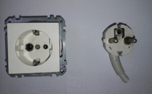
E type socket
E type socket
Image Credit – Wikimedia Commons

 To classified the difference the electric socket E and F, the standard universal Continental European system is developed which named is E/F socket and it is also known as CEE 7/7.

The earthling clip is attached with the E type socket’s top and bottom parts and female part is used to keep contact with the pin which is placed in the ground.

Read more about Current Divider Circuit

F Type:

The countries where this type of electrical socket is uses they are Sweden, Austria, Norway, Spain, Finland, Eastern Europe.This type of socket is not placed in underground. This F type sockets also known as CEE 7/4. The sockets of F type have rates about 16 A.

The sockets contain plug which width would be around 5 mm and lengthof measuring the socket is about 19.1mm.The distance length from the imaginary line of power pin and ground pin is about 16.2 mm.

G Type:

This type of electrical socket is uses in the countries of the world they are Ireland, Malta, Singapore, Arabian, United Kingdom, Peninsula and Hong Kong.This type of socket is not placed in underground. The sockets of F type have rates about 12 A.

The sockets contain three number of plug.The centre earth pin diameter is near about 2.2 mm and the socket is about 23 mm. The neutral pin diameter is about 0.8 mm and length of measuring is about 18 mm. The distance length from the imaginary line of power pin and ground pin is about 22 mm.

Read more about Is Voltage The Same In Parallel

H Type:

H type of electrical socket is uses in the countries of the world they are Israel, Palestine. This type of socket is not placed in underground. The sockets of H type have rates about 16 A.
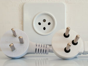
Israeli type H plugs and socket
H type socket
Image Credit – Wikipedia Commons

The sockets contain three number of plug. The center earth pin diameter is near about 4.5 mm and the measuring length is about 20 mm. The neutral pin diameter is about 0.8 mm and length of measuring is about 19 mm. The distance length from the imaginary line of power pin and ground pin is about 10 mm.

I Type:

I type of electrical socket is uses in the countries of the world they are China, New Zealand, Argentina, Asian countries, Papua New Guinea.This type of socket is not placed in underground. The sockets of F type have rates about 11 A.

J Type:

Contain off set earth pin and rate carried about 13 A.

K Type:

Three pins are used and it is grounded.

L Type:

Contain rate near about 15 A and used is Chile and Italy.
Diode Logic vs Transistor Logic: A Comprehensive Comparison

diode logic vs transistor logic

Diode Logic (DL) and Transistor Logic (TL) are two fundamental concepts in digital electronics, each with its unique characteristics, advantages, and disadvantages. This comprehensive guide will delve into the technical specifications, theoretical explanations, and hands-on details of these two logic systems, providing a valuable resource for electronics students and enthusiasts. Diode Logic (DL) Diode Logic … Read more

Vane Pump Working, Parts, Types and Applications: Detailed Facts

vane pump 279x300 1

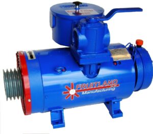
The vane pump working in automobile sectors, air conditioning system and power steering for the vehicles. The vane pump working is not suitable for high viscous liquid substance, it is suitable for moderate viscous liquid.

Vane positive displacement pump is a part of positive displacement pump. These vane pumps in various situation of the pressure deliver a fixed amount of flow rate. This vane positive displacement pump is also known as self priming pump. Inside this pump the liquid is pressurized under the impact of the vane.

This vane pump is not applicable for the liquid which is in high viscous. By the help of this pressure of the liquid is changes from high to low. For moderate and low viscous liquid this type of pump is absolutely appropriate. The liquids are such as liquid petroleum gas, ammonia, water, solvents, petrol and many more.

Read more about Liquid Refrigerant Coolant: Need to know Facts

Vane pump working
Vane pump working
Image Credit – Wikimedia Commons

Read more about What are Valves Uses: Critical Insights and Facts

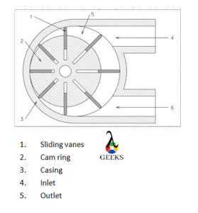
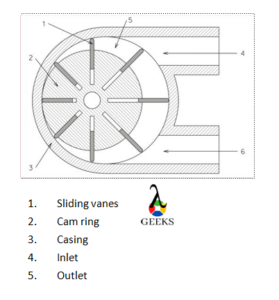
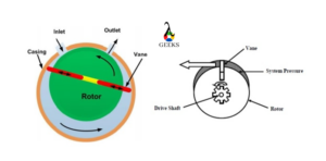
It classified as the sections of suction or vacuum pump. It is very similar to scroll compressor. The vane pump is contained some equipment such as impeller, casing, runner, vane. The multiple vanes are rotate when the rotor takes its motion. In the vanes impellers are placed.

The updated versions of the vane positive placement pump have a contact surface in the contact line between the rotor and stator.

The vane pumps are uses in a large amount in the field of automobiles, air conditioning system, steering of vehicles, fuel transport, loading of fuel in terminals.

In the vane displacement pump the vane is present and by taking of the pump liquid substance is lifted to the desired area of the fields. Inside the rotor of the pump one or more than one vane are installed and it moves under the cavity. The pressure relief valve is also placed in the pump thus it could unwanted pressure is produce inside the rotor that it could not able to failure the pump.

Vane pump parts:

In the vane positive displacement pumps a fluid substance is flow from one place to another place in low pressure to high pressure. The length can be varied for keeping contact pump’s wall as well as vane rotors.

The parts of the vane positive displacement pump and their related facts are given below,

Vane pump parts
Parts of vane pump

Shaft:

The shaft of the pump is placed in the rotor. When the rotor is moves under taking the power from the prime mover the shaft also starts to move in a rotation motion. The shaft is connected in the motor of the pump with the help of prime mover.

Casing:

Casing is equipment which is works as the protection of the system. In vane positive displacement pump the casing is use to protect the pump. All parts of the pump are protected under the casing.

Casing is classified in two sections and they are,

  • Inlet port
  • Outlet port

Inlet port:

Fluid is entering when pressure of the liquid is compressed and sucks the liquid by the inlet port.

Outlet port:

Fluid is discharge when pressure of the liquid is released and drains the liquid by the outlet port of the vane positive displacement pump.

Rotor:

Slots are carried by the rotor. The slots are placed in that manner where the distance of the each other should be same.

Cam ring:

Inside the casing cam ring is situated. Mainly the wall of the casing the cam ring is attached.

Sliding vanes:

In the rotor’s slot the sliding vanes are placed. The shape of this equipment is rectangular and spring is used to attach it with the slots. Spring is generally use for flexible movement of the sliding vanes. Sliding vanes are placed in this way that it could moves in the rotor without any problems.

Impeller:

Impellers are used to convert the energy. The impellers are placed in the vanes of the pump. When the power is generating by the impellers it convert energy mechanical to output power.

Read more about How does a Control Valve work: Critical Insights and Facts

Vane pump types:

The vane positive displacement pump is classified in three sections. They are,

Unbalanced vane positive displacement pump:

In the industry of automobiles and steering of vehicles it is used in wide range. One of the most commonly used vane type pump is unbalanced vane positive displacement pump.

The liquid substance in the vane positive displacement pumps not facing any leakage in the vane tip and housing.

Read more about What Are Valves Uses: Critical Insights and Facts

The lateral thrust which is appearing in the shaft of the rotor when the working purpose of the unbalanced vane pump is not too well. The lateral thrust can be explained as when the pressure is differentiating between the outlet valve and suction valve. This unwanted situation decreases the bearing lifetime of the shaft.

A cylindrical shaped rotor is placed in the counteracting in the housing which is also in shaped circular. The both centre for the housing and rotor not coincide to each other. The housing and rotor is placed as that manner where their distance should be same to each other.

The cylindrical rotor also contained radial grooved. The rotor is installed in the pump’s drive shaft. The grooves are carried vanes, and vanes are placed in same distance to each other and moved freely using centrifugal force in rotation method. The rotors are moved inside the cam ring. The surface contact is take place between the rotor and cam ring.

Read more about How Does A Heat Pump Work In Winter: Complete Insights, Critical FAQs

Balanced vane positive displacement pump:

In the balanced vane positive displacement pump’s inside the pressure is always stays in balanced position. The two inlets are contained by the pump. This is the main reason behind the balanced pressure. The balanced vane positive displacement pump carried one outlet and two inlets.

The inlet valves of the unbalanced pump are installed in the opposite direction to each other and outlet valve is also placed opposite to inlets valve. The offset is not present inside the balance vane positive pump.

In the casing the whole system of the balanced pump equipments are placed. The shape casing of the balance vane pump is elliptical. The centres are same for the both rotor and casing.

The purpose of the inlet valve is to suck the fluid substance from the outer side and the purpose of the outlet valve is to drainage the fluid substance to the outside of the pump.

If we go through the two vanes’ cavity then can observe that the size of the inlet valve to outlet valve is decreases.

In the balance vane positive displacement pump there is no lateral thrust is appear. The inlets and outlet valve is balancing their thrust force to each other.

Pressure amount inside the rotor in the area of the exit is too higher than the normal pressure but the position of the outlet valves are opposite to each other for this reason the force became equal and net load is not present in the bearing shaft and the lifetime of the bearing shaft is increases.

Variable displacement vane positive displacement pump:

In the variable displacement vane positive displacement pump the vanes of the rotor is not connecting directly to the housing.

The pockets sizes are different for the variable displacement vane positive displacement pump and also allow the different size. Size of the pockets can be change by the help of the adjusting screw.

Delivery rates are also different for the variable displacement vane positive displacement pump.

When the adjusting screw is moves in upward and downward direction as the same time reacting ring also moves in upward and downward in same time. Due to the he reaction ring movement changing the centre of the both rotor and ring is changes.

A ring is present in the variable displacement vane positive displacement pump’s middle portion of the casing and vane. This ring shaped equipment is known as reaction ring. This rings works as a connector between the spring and adjusting screw.

The flow rate is changes due to changes sizes of the pockets in the vane pump’s rotor.

Vane pumps working:

The vane positive displacement pump working process is briefly discuses in below,

  1. At the beginning of the process starting the power is generated by the motor which is driven by electric and power is go through by the shaft of the rotors. The rotor and shafts are connected to each other and when the rotor is start to move by using centrifugal pump the shaft is also moved.
  2. Multiple vanes are carried by the rotor.
  3. The outside liquid substance is hit the vanes of the shaft that time kinematic energy is convert into speed and goes into the casing.
  4. In the casing pressure is increases and liquid is sucks by the inlet valve.
  5. Pressure is squeezing and drain by the discharge valve.
Working of vane pump

Vane pumps application:

The applications of the vane positive displacement pump is given below,

  1. Filling up for the liquid petroleum gases’ cylinders.
  2. Bulk transferring is done by the help of this vane positive displacement pump for ammonia and liquid petroleum gas.
  3. Beverage processing done by this vane positive displacement pump.
  4. In gas application vane positive displacement pump is widely used.
  5. In automobile sector vane positive displacement pump is used.
  6. In oil application vane positive displacement pump is used.
  7. Where high pressure is used as the application there vane positive displacement pump is used. In automobile sectors for steering of the vehicles this pump is used.
  8. In air conditioning system vane positive displacement pump is used.

Mastering the Intricacies of Multi-Tap Transformers: A Comprehensive Guide

multi tap transformer

A multi-tap transformer is a versatile electrical device that features multiple taps or connections on its secondary winding, allowing for various voltage output levels. This unique design makes multi-tap transformers invaluable in applications that require multiple voltage levels or where voltage adjustments are necessary, such as in industrial, commercial, and residential power systems.

Understanding the Fundamentals of Multi-Tap Transformers

At the core of a multi-tap transformer is the principle of electromagnetic induction, where the primary and secondary windings are electrically isolated but magnetically coupled. The voltage ratio between the primary and secondary windings is determined by the turns ratio (N1/N2), where N1 is the number of turns in the primary winding and N2 is the number of turns in the secondary winding.

In a multi-tap transformer, the secondary winding is divided into multiple taps, each with a different number of turns. This allows for the generation of various voltage output levels from a single transformer, making it a versatile and efficient solution for power conversion and distribution applications.

The voltage (V) across a winding can be calculated using the formula:

V = N × I × K

Where:
– N is the number of turns in the winding
– I is the current flowing through the winding
– K is the winding factor, which accounts for the spatial distribution of the wire within the winding

Additionally, the current (I) in a winding can be calculated using Ohm’s law:

I = V/R

Where R is the resistance of the winding.

Hands-on Considerations for Multi-Tap Transformer Applications

multi tap transformer

When working with a multi-tap transformer, there are several key factors to consider to ensure optimal performance and safety:

  1. Voltage Selection: Carefully choose the appropriate voltage tap based on the specific requirements of your application. This may involve considering factors such as load, power consumption, and voltage regulation.

  2. Wiring Diagram: Follow the correct wiring diagram for the specific multi-tap transformer and application. Improper wiring can lead to safety hazards and equipment damage.

  3. Rectification: If your application requires DC voltage, ensure that the multi-tap transformer is connected to an appropriate rectifier circuit, such as a bridge rectifier, to convert the AC voltage to DC.

  4. Grounding: Properly ground the multi-tap transformer and the entire circuit to ensure safety and stability. Grounding helps to dissipate any potential electrical charges and provides a path for fault currents.

  5. Capacitance and Resistance: Select appropriate capacitors and resistors for the rectifier circuit based on the multi-tap transformer’s output voltage and current ratings. This helps to smooth the output voltage and regulate the current flow.

Practical Examples and Numerical Calculations

Let’s explore some practical examples and numerical calculations to better understand the application of multi-tap transformers.

Example 1: Calculating Voltage Outputs

Consider a multi-tap transformer with a primary winding of 1000 turns and a secondary winding with 100 turns and five taps. If the primary voltage is 220V AC, calculate the voltage at each tap.

Using the formula V = N × I × K, where N = 100, I = primary voltage / turns ratio, and K = 1 (assuming a winding factor of 1 for simplicity):

  • Tap 1 (N = 100, I = 220V / (1000/100) = 22V, K = 1): V1 = 100 × 22V × 1 = 2200V
  • Tap 2 (N = 95, I = 220V / (1000/95) = 21.7V, K = 1): V2 = 95 × 21.7V × 1 = 2066.5V
  • Tap 3 (N = 90, I = 220V / (1000/90) = 21.4V, K = 1): V3 = 90 × 21.4V × 1 = 1926V
  • Tap 4 (N = 85, I = 220V / (1000/85) = 21.1V, K = 1): V4 = 85 × 21.1V × 1 = 1798.5V
  • Tap 5 (N = 80, I = 220V / (1000/80) = 20.8V, K = 1): V5 = 80 × 20.8V × 1 = 1664V

Example 2: Selecting the Appropriate Tap and Calculating Rectifier Circuit Parameters

Suppose a circuit requires a 12V DC power supply. The multi-tap transformer has a secondary winding with 100 turns and five taps, with the following voltage ratings:
– Tap 1: 10V
– Tap 2: 12V
– Tap 3: 14V
– Tap 4: 16V
– Tap 5: 18V

In this case, we would choose Tap 2, which provides the required 12V DC output.

To design the rectifier circuit, we can use a bridge rectifier. The ripple voltage (Vr) can be calculated using the formula:

Vr = I / (2 × f × C)

Where:
– I is the load current
– f is the line frequency (50 or 60 Hz)
– C is the capacitance value

Assuming a load current of 1A, a line frequency of 50 Hz, and a desired ripple voltage of 1V:

C = I / (2 × f × Vr) = 1A / (2 × 50Hz × 1V) = 10,000μF

For the resistor, the power (P) can be calculated using the formula:

P = V^2 / R

Where V is the voltage and R is the resistance. Assuming a voltage drop of 1V across the resistor:

R = V^2 / P = 1V^2 / 1W = 1 Ohm

Conclusion

Multi-tap transformers are versatile and essential components in power conversion and distribution systems. By understanding the theoretical principles, hands-on considerations, and practical examples, you can effectively design, implement, and troubleshoot multi-tap transformer-based circuits to meet the diverse power requirements of your applications.

Reference:

  1. Multi-tap transformer newb questions | All About Circuits
  2. Question about Multi-Tap Transformer – Electronics Stack Exchange
  3. Center Tapped Delta Transformer 5% Limitation – Mike Holt’s Forum
  4. How to Wire a Multi-tap Transformer – Functional Devices, Inc.

3 Brake Fluid Types: Detailed Facts

Disc brake

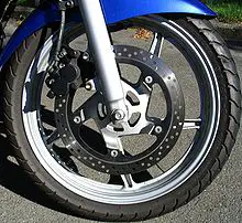
This article discusses about brake fluid types. The braking fluid is used as hydraulic fluid inside the braking system of vehicles.

Hydraulic force is applied with the help of hydraulic fluid. The fluid uses Pascal’s law for transferring the force from one end to other. We shall see more about types of braking fluid, mechanism of braking system and other related topics.

What is braking fluid?

The type of hydraulic fluid that is used in braking systems and clutches of automobiles.

Generally the braking force applied to the braking pedal is very less than the actual force needed to stop the vehicle in motion. The braking fluid converts this force into pressure and amplifies it enough that the resulting amplified force can stop the vehicle.

brake fluid types
Image: Disc brake

Image credits: anonymous, Disc brakeCC BY-SA 3.0

Define brake fluid types

Brake fluids are of four types. The designation of these brake fluids start with DOT that means Department of Transportation. The four types are-

DOT 3

DOT 3 is a glycol based braking fluid. The term is a standard term used in US. DOT 3 is equivalent to SAE J1703.

DOT 4

DOT 4 is also a glycol based braking fluid generally used as a temperature upgrade for DOT 3. Most cars after 2006 used DOT 4 brake fluid as their standard braking fluid.

DOT 5

A braking fluid that is silicone based and also it is completely different from the series of DOT (2,3,4,5.1) It does not mix with water and other brake fluids. It is recommended that this braking fluid should not be mixed with other braking fluids.The biggest advanatage of silicone over other materials is that silicone based fluid has more stable viscosity index with working conditions having a wide variety of temperature values.

DOT 5.1

Although, DOT 5 was a better version among other DOT versions. Lack of its acceptance led rise to DOT 5.1 which is again a glycol based braking fluid. It gives functioning similarities with silicone based braking fluid and can be termed as non silicone version of DOT 5. That is a version having similar properties of DOT 5 while using Glycol ether based raw materials.

Brake fluid properties

The braking fluid undergoes extreme conditions as the vehicle runs sometimes on smoother road and sometimes on rough and bumpy road. The weather may be hot sometimes, rainy sometimes and sometimes cold.

According to these conditions the braking fluid cannot be changed every now and then. So it has to have properties such that it can bear extreme situations. The ideal properties for a braking fluid are-

  • High breaking point- As the vehicle experiences immense heating during its operation, it is recommended to have a braking fluid which can operate at high temperatures.
  • Good low temperature properties– Sometimes the temperatures are below normal levels during cold, at this time the braking fluid may solidify if it does not have good low temperature properties.
  • Good viscous properties- The braking fluid should have an optimum amount of viscosity. It should not be loose and also not thick that it does not move easily.
  • Anti corrosive properties– The braking fluid should have anti corrosive properties otherwise it will corrode the material used in braking lines damaging the entire braking system.
  • Physical stability– A good braking fluid has good physical stability that means it should not get distorted or change its phase once it is subjected to huge amount of force and pressure.
  • Chemical stability- A good braking fluid does not mix with other liquids, it should have good chemical stability. It should maintain its chemical structure and should not be easily contaminated by outside impurities.
  • Compressibility- The entire functionality of braking fluid depends on its compressibility. If the compressibility is not good then it won’t be able to provide required pressure and so the braking system will fail which in turn means that the vehicle won’t be stopped.

Bike brake fluid types

Bikes usually use two types of braking fluids. These fluids are discussed in detail below-

  • DOT fluid- Above section discusses about DOT fluids in detail. They are mostly made of Glycol Ether based materials and generally each higher version has a better working temperature range. Except for DOT 5 which is a silicone based braking fluid and that has better properties than DOT 2, DOT 3 and DOT 4.
  • Mineral oils– This is the normal mineral oil that we purchase from grocery stores. This is generally meant for lighter vehicles such as two wheeler.

DOT brake fluid types

As discussed in the sections above, DOT brake fluids are classified into many types. Typical basis of classification is the working properties and the raw materials used while making the braking fluid.

The types of DOT braking fluid are-

  • DOT 2– Has a low working range of temperature.
  • DOT 3– Has a greater working temperature range than DOT 2.
  • DOT 4- Has even greater working temperature range than DOT 2 and DOT 3.
  • DOT 5- This is made up of silicone based materials and has better properties.
  • DOT 5.1– Although made of Glycol Ether based materials, it has similar properties as that of DOT 5.

Car brake fluid types

In cars usually glycol ether based brake fluids and silicone based brake fluids are used. These fluids are discussed in above sections. Most commonly used braking fluids in cars are DOT brake fluids. More specifically, following DOT brake fluids are used-

  • DOT 3- As discussed above it is a Glycol Ether based braking fluid that is used in lighter vehicles. This braking fluid can be used in hatchback cars that are light in weight. It has a smaller range of working temperature.
  • DOT 4- As discussed above, it is also a Glycol Ether based braking fluid that is used for comparatively heavier vehicles such as SUVs. This braking fluid has a greater working temperature range.

Auto brake fluid types

In autos, usually DOT 3 type of braking fluid is used. As an auto is considered in lighter weight vehicle type, it does not need higher versions of braking fluid like DOT 4 and 5. DOT 3 is sufficient for autos.

Boiling Point And Pressure: What, How, Relationship, Effects And Detailed Facts

Boiling

This article discusses about the relation between boiling point and pressure. A misconception lies among us that the boiling point is related to temperature only. But primarily it is the pressure which is responsible for the boiling to take place.

The boiling of liquid starts when the vapour pressure of the liquid starts touching the value of ambient or surroundings pressure. The pressure at which boiling takes place is called as saturation pressure. Pressure of the liquid keeps on increasing with increasing temperature. We shall study more about this relationship in this article.

What is partial pressure?

In simple words partial pressure is defined as the pressure exerted by a certain type of liquid molecules in a mixture.

This pressure is the exact same pressure that the liquid molecules must have exerted if these were the only molecules occupying the whole volume. Partial pressure term comes into play when there are more than one type of liquid molecules present in the system.

What is vapour pressure?

Vapour pressure is the pressure exerted by the liquid molecules when they are about to change into gaseous molecules.

The vapour pressure increases with temperature. The surface of the liquid starts boiling when the surface vapour pressure is equal to the ambient pressure. The atmosphere exerts some pressure on the liquid, when this value of atmospheric pressure is reached by vapour pressure, boiling starts taking place. 

How does pressure affect boiling point?

Pressure, as discussed above, is one of the most important factor that affects directly the boiling point of any liquid.

For the surroundings, if the surrounding pressure is very high, it will take more time and more heat for the liquid to reach the ambient pressure value and hence the boiling point of the liquid will be more. When the ambient pressure is low then the liquid will reach the ambient pressure value soon. In this case, the boiling point will be lower as compared to boiling point at surroundings with high pressure.

Boiling point and pressure relationship

Now we have a clear view of how pressure affects the value of boiling point. The main factor affecting the boiling point is atmospheric pressure. (Although temperature also plays an active role)

We shall focus our discussion on relation between pressure and boiling point only. Lets us assume that the heat transfer rate is constant. This way the liquid molecules will slowly get heated up resulting in increase in their vapour pressure. As the vapour touches the ambient pressure, the liquid will start boiling.

boiling point and pressure
Image: Boiling

Image credits: user:Markus SchweissKochendes wasser02CC BY-SA 3.0

Boiling point and pressure equation

The equation which draws the relationship between boiling point and pressure numerically is called as Clausius-Clapeyron equation.

The Clausius-Clapeyron equation is given below-

gif

Does boiling point increase with pressure?

As and when the pressure of the ambient increases, the boiling point also increases but only upto the critical point.

It is the point where the properties of both the phases, that is, liquid and gases, are exhibited by the substance. We shall more about critical point in later sections of this article. Also, we can note this fact that the boiling point of the liquid decreases when the pressure drops until the triple point is reached.

How does boiling point increase with pressure?

The boiling point can be defined as the value of temperature at which the vapour pressure of liquid becomes equal to the ambient pressure. This value of temperature depends on the ambient pressure.

If the ambient pressure is more, it takes more time for the liquid’s vapour pressure to reach the value ambient pressure. The heat source constantly supplies heat to the liquid to increase its pressure. When the pressure at the outside is more then the boiling time will also be more.

How does water boil at low pressure?

At low pressures, the water starts boiling in a very short time. This is because the time required for the vapour pressure to reach the value of ambient pressure is less.

A notable example is that the food is cooked very fast on mountains. This is because the ambient pressure is very less compared to the pressure at sea level. The liquid takes more time to boil when it is at sea level. 

Does water boil faster at high or low pressure?

We have discussed rigorously about the effect of pressure on boiling point. It is made to us very clear that the water will start boiling faster at lower pressures.

The reason being the same as discussed above. That is, the time required for the vapour pressure to reach the value of ambient pressure is less. The water starts boiling when the vapour pressure reaches the value of ambient pressure.

Factors affecting boiling point

We have discussed a lot of things about what affects the boiling point. Let us get a more detailed view on these factors.

The factors affecting the boiling point are given below-

  • Temperature– Temperature is responsible for increasing or decreasing the vapour pressure of the liquid. When the temperature is high, the vapour pressure increases and likewise, when the pressure is low, the vapour pressure decreases.
  • Vapour pressure– When the vapour pressure reaches the value of ambient pressure, the liquid starts boiling. The pressure exeerted by the liquid when it is about to change its phase is called as vapour phase.  
  • Atmospheric pressure– As the name suggests, the atmospheric pressure is the pressure exerted by atmosphere. Atmospheric pressure plays a very important role in determining the boiling point of the substance. If the pressureexerted by atmosphere is less then the boiling point will also be less and on the other hand the boiling point will be more if the pressure exerted by the atmosphere is more.

What is critical point?

Simply put, critical point of a substance is that point at which the properties of liquid such as density, temperature, pressure etc are equal to that of its own gaseous state.

This can be said as an equilibrium state where the substance exists in both the liquid and gaseous phase. The molecules exhibit properties of both liquids and gases at the same time.

What happens at critical point?

When the temperature of the liquid is raised, the density of the liquid falls down and simultaneously the density of gas starts increasing.

When the densities of both liquid and gas become equal, then the particular point is called as critical point. Here both gas and liquid phase properties are exhibited by the substance.

The Pivotal Role of Logic Gates in Modern Entertainment Systems

logic gates role in modern entertainment systems

In the ever-evolving world of digital technology, logic gates have become the unsung heroes of modern entertainment systems. These fundamental building blocks of digital electronics are responsible for the complex processing and manipulation of digital signals, enabling entertainment systems to perform intricate tasks with precision and efficiency. Understanding Logic Gates: The Backbone of Digital Circuits … Read more

Transformer Voltage Drop: A Comprehensive Guide for Electronics Students

transformer voltage drop

The voltage drop in a transformer is a critical factor in the design and operation of power systems. It is the decrease in voltage from the input to the output of the transformer, and it is caused by the resistance and reactance of the transformer windings. Understanding the causes, measurement techniques, and calculation methods of transformer voltage drop is essential for electronics students to design and analyze power systems effectively.

Understanding Transformer Voltage Drop

Transformer voltage drop occurs due to the resistance and reactance of the transformer windings. The resistance of the windings causes a voltage drop due to the current flowing through them, while the reactance of the windings causes a voltage drop due to the inductive and capacitive effects.

The voltage drop in a transformer can be calculated using the following formula:

Voltage Drop = I × (R + jX)

Where:
I is the current flowing through the transformer
R is the resistance of the transformer windings
X is the reactance of the transformer windings

The resistance and reactance of the transformer windings can be measured or obtained from the transformer’s datasheet.

Measuring Transformer Voltage Drop

transformer voltage drop

Transformer voltage drop can be measured using various methods, including the use of current transformers (CTs) and voltage transformers (VTs).

Current Transformers (CTs)

A CT is a device that produces a secondary current proportional to the primary current. By measuring the voltage drop across the CT, the transformer voltage drop can be calculated using the formula:

Voltage Drop = I × (R_CT + R_load)

Where:
I is the current flowing through the transformer
R_CT is the resistance of the CT
R_load is the resistance of the load connected to the transformer

Voltage Transformers (VTs)

A VT is a device that produces a secondary voltage proportional to the primary voltage. By measuring the voltage drop across the VT, the transformer voltage drop can be calculated using the formula:

Voltage Drop = V_primary - V_secondary

Where:
V_primary is the primary voltage of the transformer
V_secondary is the secondary voltage of the transformer

Artificial Neural Networks (ANNs)

The voltage drop in a transformer can also be estimated using artificial neural networks (ANNs). ANNs are computational models that can learn to recognize patterns and make predictions based on data. In a study titled “Estimation through ANN of Voltage Drop Resulting from Overloads on Power Transformers”, researchers used ANNs to estimate the voltage drop in power transformers based on the transformer’s load and other operating conditions.

Factors Affecting Transformer Voltage Drop

The voltage drop in a transformer can be affected by several factors, including:

  1. Transformer Load: The voltage drop increases as the load on the transformer increases. This is due to the increased current flowing through the transformer windings.

  2. Transformer Winding Resistance: The voltage drop is directly proportional to the resistance of the transformer windings. Transformers with higher winding resistance will have a higher voltage drop.

  3. Transformer Winding Reactance: The voltage drop is also affected by the reactance of the transformer windings. Transformers with higher winding reactance will have a higher voltage drop.

  4. Transformer Power Loss: The voltage drop in a transformer can also be affected by the transformer’s power loss. Power loss in a transformer can be divided into no-load loss and full-load loss. No-load loss is a constant loss that occurs even when no load is connected to the transformer, while full-load loss varies with the load on the transformer. The power loss can be used to calculate the voltage drop in the transformer.

Calculating Transformer Voltage Drop

To calculate the voltage drop in a transformer, you can use the formula:

Voltage Drop = I × (R + jX)

Where:
I is the current flowing through the transformer
R is the resistance of the transformer windings
X is the reactance of the transformer windings

Alternatively, you can use the formula:

Voltage Drop = I^2 × (R_winding + R_load)

Where:
I is the current flowing through the transformer
R_winding is the resistance of the transformer windings
R_load is the resistance of the load connected to the transformer

The resistance and reactance of the transformer windings can be obtained from the transformer’s datasheet or measured using appropriate equipment.

Practical Applications and Importance for Electronics Students

Understanding transformer voltage drop is essential for electronics students who are designing and operating power systems. Accurate calculation and measurement of transformer voltage drop can help in the following applications:

  1. Transformer Sizing: Knowing the voltage drop in a transformer is crucial for selecting the appropriate transformer size and rating for a given application.

  2. Voltage Regulation: Transformer voltage drop can affect the voltage regulation of a power system. Analyzing and minimizing the voltage drop can help maintain the desired voltage levels at the load.

  3. Efficiency Optimization: Reducing the voltage drop in a transformer can improve the overall efficiency of the power system, leading to energy savings and reduced operating costs.

  4. Fault Analysis: Transformer voltage drop can be used as a diagnostic tool to identify and troubleshoot issues in power systems, such as overloading, winding faults, or transformer aging.

  5. Power Quality: Excessive voltage drop in a transformer can lead to power quality issues, such as voltage fluctuations, harmonics, and power factor problems. Understanding and mitigating transformer voltage drop can help maintain the desired power quality.

By mastering the concepts and techniques related to transformer voltage drop, electronics students can develop the necessary skills to design, analyze, and optimize power systems in various applications, such as industrial, commercial, and residential power distribution.

Reference:

  1. Study of Distribution Transformer Voltage Drops in Feeder 5 Out Going Districts 4 and 6 at PT PLN Persero Tarakan City North Kalimantan
  2. Voltage Measurement on a Current Transformer (CT) – Physics Forums
  3. Estimation through ANN of Voltage Drop Resulting from Overloads on Power Transformers
  4. Calculating Voltage Drop in a Transformer | All About Circuits
  5. Voltage Drop Calculation Through Transformer – Mike Holt’s Forum