Deriving the Frequency Spectrum from Time Domain Data: A Comprehensive Guide

how is the frequency spectrum derived from time domain data a comprehensive guide

Deriving the frequency spectrum from time-domain data is a fundamental technique in signal processing, enabling the analysis of periodic behavior, identification of dominant frequencies, and extraction of valuable insights from complex waveforms. This comprehensive guide will delve into the mathematical foundations, practical implementation, and real-world applications of this powerful analytical tool. Understanding the Fourier Transform … Read more

15 Radioactive Decay Examples: Detailed Explanations

800px MRI Philips 300x274 1

In this article Radioactive decay examples are derived. Radioactive process is actually a continuous breakdown process of a matter’s atomic nucleus. In this process energy is emitted from any matter’s nucleus.

16+ radioactive decay examples are given in section of below,

  • Medical equipment
  • Glass
  • Ceramics
  • Clocks and watches
  • Smoke detector
  • Fertilizers
  • Gas Lantern Mantles
  • Food
  • Glowing items
  • Recycled metal
  • Irradiated Gemstones
  • X ray imaging
  • Security
  • Measurement
  • Space exploration
  • Human body

Medical equipment:

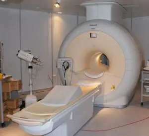
In various machines in the medical field radioactive element is widely used. From where radioactive decay is emitted these types of material are used in the medical field for treating health of a patient. Nuclear Regulatory Commission department regulate the use of radioactive decay in medical field.

Near about one third patients are admitted for acted a rare and fatal liver disease using radioactive or radiation materials.  The radioactive or radiation materials are called radio pharmaceuticals. To reduce the tissue of the cancerous, reduce and shrink a tumor this radioactive object is used.

800px MRI Philips
Image – Medical equipment;
Image Credit – Wikipedia Commons

Glass:

In the industry of glassware the radioactive decay is used. Thorium – 232 and potassium – 40 radioactive type objects is used inside the glassware factory. Some glass made product also contain uranium this type of glass is called Vaseline glass.

Glass is transparent amorphous solid and it is non crystalline. In the glass others chemical are also present like silica.

Radioactive decay examples
Image – Glass;
Image Credit – Wikimedia Commons

Ceramics:

Thorium, uranium, potassium radioactive type objects is used inside the ceramics. Ceramics can be divided in two categories as non metallic material and inorganic material. In the field of production engineering the examiner are tried to new type products of ceramics that general people can use in their everyday lifestyle.

In almost everywhere ceramics are present. In bricks, glass, plates even in toilet the ceramic made of products are present.  In automobile, clock and watches, snow skies, airplanes, appliances, space shuttles the ceramics products are available. Even in some superconductors ceramics presence can be observe.

In the ceramics the objects which are present they are powders, water, earthen elements, mixture of clay and mixing all together the desired object is made.

800px Boeotian Geometric pottery AM of Thebes 201170
Image – Ceramics;
Image Credit – Wikimedia Commons

Clocks and watches:

In our daily the most common and useful radioactive example is clocks and watches. Promethium – 147 radioactive type objects is used inside the clocks and watches. Another type radioactive type objects is used inside the clocks and watches is Hydrogen – 3.

For this reason luminous type dials actually a compromising. For this reason in dark area we easily can see the time without any hassle. Now a day where this modern type watches is used. In older watches and clocks Radium – 226 is used.

Radium Dial
Image – Clock and watches;
Image Credit – Wikipedia

Smoke detector:

The term for the smoke detector is smoke alarm. The radioactive example which is use in our regular life this is the smoke detector. Mainly alpha decay is used in the smoke alarm. Americium – 241 this radioactive object is used inside the smoke detector.

The Americium – 241 radioactive elements is actually particularly placed in the middle portion of the charged plates. From Americium – 241 element release alpha decay to the environments.

Two plates which are charged are used to construct the design of smoke detector. Others things which are used in the design of the smoke detector they are, a battery, a mechanism of alarming, a detector battery. The terminals are attached to the equipment of the smoke detector in a very interesting way. One terminal of the smoke detector is attached with the detector of current and another one terminal is attached with the positive side plate of the smoke detector.
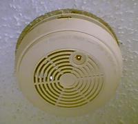
Ceiling smoke alarm
Image – Smoke detector;
Image Credit – Wikimedia Commons

Others some facts which are we to concern about is listed below,

  • At least in every 9 – 10 years the smoke detector should be definitely replaced.
  • The connection of the smoke detector always interconnected.
  • Large buildings should contain more smoke detector.
  • Monthly checking and maintenance is needed.

Fertilizers:

Fertilizer is an element which is mainly used in agriculture field for improve the productivity and growth of the plants. Fertilizer actually a element which is enhance the fertility naturally of the soil or elements which carry the chemicals alternatively use as soil by prior crops.

In the fertilizer the radioactive elements are used they are uranium and thorium. The other chemical element which are contain by the fertilizer is hydrogen, nitrogen, oxygen, phosphorus, calcium, sulfur, sodium, silicon, aluminium and many more.
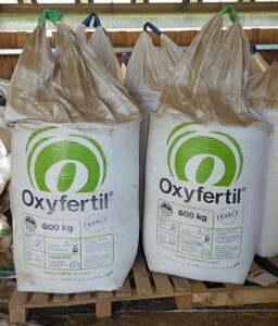
Oxyfertil fertilizer
Image – Fertilizer;
Image Credit – Wikimedia Commons

Gas Lantern Mantles:

Thorium – 232 radioactive elements is used in the gas lantern mantles. This gas lantern mantles actually incandescent lights. When fuel is burn like kerosene, propane and white gas heat is produce and as a result mantles is made from which light is comes.

The gas lantern mantles components made of ceramics other elements present in this is cerium oxide, thorium oxide and magnesium oxide. The construction of the gas lantern mantles is very simple.
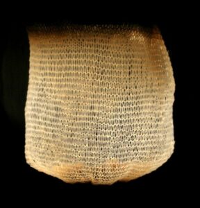
800px Glowing gas mantle
Image – Gas lantern mantles;
Image Credit – Wikipedia

Food:

There is lots of food is present in nature from their radioactive decay is always emitted.  The food items are,

Brazil nut – From the Brazil nut near about 12000 picocurie per kilogram radiation decay is emitted.

Butter beans – From the butter beans near about 4600 picocurie per kilogram radiation decay is emitted.

Bananas – From the bananas near about 3500 picocurie per kilogram radiation decay is emitted.

Avocados – From the Avocado near about 2500 picocurie per kilogram radiation decay is emitted.

Water – From the water near about 100 picocurie per kilogram radiation decay is emitted.

Red meat – From the red meat near about 3000 picocurie per kilogram radiation decay is emitted.

Peanut butter – From the peanut butter near about 120 picocurie per kilogram radiation decay is emitted.

Glowing items:

In lots of glowing item which we are used in our daily life radioactive element is present. Mainly in the glowing item thorium and uranium are used. These items can glow in dark places without battery or electricity.

In the glowing items mainly very low level radiation of beta is emitted. The emission of the beta radiation easily can be stopped with help of cloth or sheet of paper.

Recycled metal:

We are known the process of the recycle is very convenient for us and also for our surrounding. But some time the process of recycle can causes some unwanted bad situation. The metals which are used again and again for recycling causes emitting of radiation decay. We always should some take some care of it,

  1. Taking a distance
  2. Time limitation
  3. Checking shielding

Irradiated Gemstones:

In lots of gemstones which we are used in our daily life radioactive element is present. Mainly in the irradiated gemstone item gamma radiation is continuously emitted. The irradiation is a term which meaning is very board. In irradiated gemstones full range of radiation of electromagnetic present and also visible light, X rays, ultraviolet rays, infrared radiation is present.

X ray imaging:

X ray imaging is a very process which is done without any pain and it is very speedy process. From this x ray imaging the radiation is emitted. Mainly by the help of x ray a picture is taken for any particular place of our body.
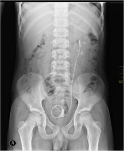
800px Medical X Ray imaging QGT06 nevit
Image – X ray image;
Image Credit – Wikipedia Commons

Beam of the ray is going through of our body and after that absorbed different amount of radiation which is depend upon the material density.

But excess amount of doing x ray imaging is not good for our body.

Mainly the images are taking by the help of x ray process is,

  • Arthritis
  • Bone cancer
  • Osteoporosis
  • Dental decay
  • Fracture
  • Blocked blood vessels
  • Breast cancer
  • Swallowed items

Security:

In our modern society the most and effective security process is done for security is radiation decay. When a man is pass through the radiation decay test an image is clearly comes to the examiner that what object he is carrying. Mainly this process x ray is done. Alpha radiation is emitted in this process.

Measurement:

In the special measuring instruments like gauges and devices the radiation of radioactive elements are used thus we can get appropriate measurement and accuracy. Not only in measuring devices is the radiation radioactive also used in checking instrument. For checking the fluid levels, defects present in the welds, very small measure in physical this process is followed.

Read more about Gauge pressure : It’s Important Properties with 30 FAQs

Space exploration:

In space exploration the radiation of radioactive is uses. Actually interstellar space is very dark for this reason the surrounding temperature became very low. The temperature reaches about zero degrees centigrade. For overcome this problem radioactive element are use so that the equipment of the aircraft can move and don’t freeze neither the equipment could not open up.

The radiation of the radioactive elements gives heat to the equipment of the aircraft.

Piers Sellers spacewalk
Image – Space Exploration;
Image Credit – Wikipedia Commons

Human body:

From our body very little amount of radiation of radioactive is emitted. From our body mainly carbon – 14 radioactive element is present. For this reason the archaeologists easily can determine the range of age for skeleton. The main source of the radioactive in our body is when we took breathe from environment little amount is absorbed.

Frequent Asked Question:-

Question: Write disadvantages of radioactive decay examples.

Solution: Some disadvantages of radioactive decay examples is given below,

  • Irritation in skin
  • Hair loss
  • Difficulty in swallowing
  • Bladder infection
  • Sore throat
  • Dry mouth

5 Radioactive Decay Types: Uses, Properties And Examples

Alpha

This article discusses about radioactive decay types. We know that atoms are held together by a force called interatomic force or nuclear force.

When an unstable atom wants to attain a stable state, it does so by emitting a large amount of energy through radiation. This extra energy being the reason behind instability of that atom is shredded by the atom itself. This phenomenon is called as radioactivity. We shall read more about radioactivity in this article.

What is radioactivity?

As discussed in above section, it is the phenomenon in which the unstable atom loses its energy to attain stability.

The energy released is termed as nuclear or atomic energy as it is derived from the nucleus of the atom. We shall study more about radioactivity and its types in further sections of this article.

Radioactive decay types

There are many ways in which the nuclear energy can be emitted. The different types of radioactive decay are listed below-

Alpha decay

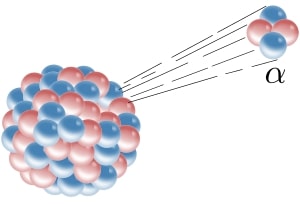
Alpha particles are those particles which consists of two protons and two neutrons (Like He atom). When the nucleus emits alpha particles in a reaction then it is called as alpha decay.

radioactive decay types
Image: Alpha Decay

Image Credits: Wikipedia

Beta decay

Just like Alpha decay, in Beta decay, the Beta particles are emitted. Beta particles are those particles which have a pair consisting of positron and neutrino or electron and anti neutrino. When positron and neutrino are emitted, it is termed as beta plus decay and similarly when electron and anti neutrino are emitted it is termed as beta minus decay.

Gamma decay

Gamma decay takes place in two steps. First nucleus emits Alpha or Beta particles and leaves the nucleus in an excited state. To achieve a stable state, nucleus emits gamma ray photons. This is called as gamma decay.

Neutron emission

In some cases, due to excessive Alpha Decay or Beta Decay, the remaining nuclei become neutron rich. These neutrons are shedded away by the process of neutron emission. This results in formation of Isotopes of different particles.

Electron capture

Sometimes, Nucleus may capture an orbiting electron. This leaves the proton alone due to which it gets converted to neutron. During this process, Neutrino and gamma rays are emitted.

Cluster Decay

In Cluster decay a nucleus heavier than Alpha particle is emitted.

Radioactive decay series example

An unstable atom undergoes a series of radioactive decays or transformations to attain a stable state. This series of transformations is termed as radioactive decay series.

A radioactive decay series is also called as radioactive cascade, the atom does not get directly converted to a stable state. Rather it undergoes many transformations to reach a stable state. Examples of radioactive decay series is given below-

  • Thorium series– In Thorium series, following elements are present- Actnium, Bismuth Lead, Polonium, Radon, Radium and Thallium. The total energy release from Thorium-232 to Lead-208 is 42.6 MeV.
  • Neptunium Series– In Neptunium series, only two isotopes are involved namely Bismuth-209 and Thallium-205. The total energy release from Californium-249 to Thallium-205 is 66.8 MeV.
  • Uranium Series– Uranium series contains the following elements- Astatine, Bismuth, Lead, Polonium, Protactinium, Radium and Radon, Thallium and Thorium. The total energy release from Uranium-238 to Lead-206 is 51.7 MeV.
  • Actinium series– The Actinium series consists of- Actinium, Astatine, Bismuth, Francium, Lead, Polonium, Protactinium, Radium, Thallium, Thorium and Radon. The total energy released from Uranium-235 and Lead-207 is 46.4 MeV.

Radioactive decay properties

We have discussed in above sections that radioactivity is the phenomenon in which an atom reduces its energy to attain a stable state. The energy released through these atoms is high enough to make an Atom bomb.

The process of radioactive decay is very random, one cannot simply tell which atom is going to disintegrate into which atom. The entire energy release process is spontaneous. The transformation theory does not tell about the particular cause inside the atom which is responsible for the emission of this extra energy.

Radioactive decay uses

Although, humans have a dangerous threat of nuclear radiation. A slight amount of exposure to radiation can cause illness, burns and severe diseases which can lead to death. Excessive amount can cause instant death.

But it can be used in a better way if the energy is harnessed in a proper manner. Let us see some uses of radioactivity-

  • Medicine– Cobalt-60 is used extensively to trap cancer cells. This is a major breakthrough in fighting cancer.
  • Electricity generation– Uranium-235 is a commonly used fuel in nuclear power plants. Even a small amount of Uranium-235 can be used to generates megawatts of electricity.
  • Treatment– Iodine-131 is used in treating hyperthyroidism. Some radioactive isotopes are used in diagnostic purposes as well as for research.
  • Measurement of thickness-The strength of penetrations if these radioactive elements can be used precise measurement of thicknesses of plastics and metals in industries.
  • X rays-X rays and CT scans employ radioactive elements which penetrate through the human skin and give a luminiscent view of human body from inside.

Radioactive hazards

If not used in a proper manner, exposure to radiation can cause irrepairable damages to human body as well as other life on Earth.

Below is a list of few of the hazards that are caused by exposure to radioactivity-

  • Skin burn– Long exposure to sun can cause burns on skin. This can be observed by tanning that is darkening of the skin. If the skin is exposed to sunlight for a very long time, then it can have permanent damage and sometimes cause skin cancer.
  • Radiation burns- When a person comes in direct contact with radioactive material, depending on the amount of exposure to this radiation, he/she can get radiation burns. The skin gets burnt due to the high penetration power of radioactive elements.
  • Acute radiation syndrome- This is an illness caused by intake of high amount of radiation in a very short amount of time.
  • Cancer– Radiation can cause cancer in our bodies.
  • Cardio Vascular diseases– Excessive radiation causes cardio vascular diseases which can be there for entire lifetime and can be passed on genetically.
  • Radiation cloud– Atomic blasts leave a huge radiation cloud in the atmosphere thus polluting the atmosphere with radioactive elements. These radioactive clouds then come down in the form of rain.
  • Loss of life on Earth– Due to radiation, the innocent plants and animals die because they are unaware of the threats caused by radiation in their bodies.
  • Lengthy half life of radioactive materials– Once there is a radioactive leak in an area, it has to be completely sealed for thousands of years as the half life of radioactive elements is far more than human lives. Thus to curb the effect of radiation, the entire population has to shifted and the area needs to be sealed.

Understanding the Polarity and Directional Installation of Zener Diodes

is a zener diode polarized understanding its direction of installation

Zener diodes are a specialized type of semiconductor device that play a crucial role in various electronic circuits, particularly in voltage regulation and stabilization applications. Understanding the polarity and proper directional installation of Zener diodes is essential for ensuring their reliable and efficient operation. This comprehensive guide will delve into the technical details and provide … Read more

Plate and Frame Heat Exchanger: What, How, Types, Working, Sizing, Cleaning, Applications

Plate heat exchanger dismantled pic02 216x300 1

In industrial field in various purposes “Plate and frame heat exchanger” is used. Inside the plate and frame heat exchanger the temperature and transferring of heat is always transfer from higher to lower.

In the industrial area the heat exchangers are used in a large quantity among them the Plate and frame heat exchanger is one of these.Plate and frame heat exchanger uses as a metal plate through which heat can be transfer between present of two fluids. It is carry a frame and clamped between a follower and head.

What is plate and frame heat exchanger?

Plate and Frame Heat Exchanger is a device which is most suitable heat exchanger for exchanging the pressure from low pressure to medium pressure by the medium of fluids of pressure. It is used in free cooling, boilers.

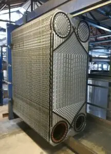
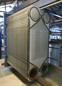
The plate and frame heat exchanger is a device which is uses in a sequence of metal plates where the heat is freely move one fluid to another fluid.  The plates of the plate and frame heat exchanger placed over each other thus it could create a sequence channel so the pressure fluid can move inside of it.

Plate and frame heat exchanger
Plate and frame heat exchanger Image Credit – Wikimedia Commons
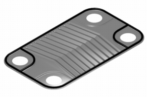
Individual plate of plate and frame heat exchanger
Image Credit – Wikipedia

How does plate and frame heat exchanger work?

The plate and frame heat exchanger is a device which is widely uses in small welded designs. The main convenience of the plate and frame heat exchanger is pressure fluid easily can distribute over metal plates.

The gaskets plates of the plate and frame heat exchanger cut down the heat through the surface of the exchanger and help in separate the medium of the hot to medium of the cold. For this reason lower temperature fluid, gas and higher temperature fluid, gas use minimal level of energy.

The working principle of the plate and frame heat exchanger is deeply derive in section of below,

At the start of the process multiple plates are stack together.

Gaskets are used inside the plate and frame heat exchanger thus it could allow preventing fluids which are entering from the alternating plates. The gaskets can easily move left or right side for creating block. In every channel of the plates two fluids will definitely flow. The holes of the gaskets plates in the plate and frame heat exchanger align in this way from a pipe just like a channel from where fluid can flow.

If we go through the plate and frame heat exchanger’s gasket plates then we can observe that the alternates’ gasket plate side is block.

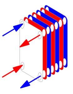
If cooler fluid can pass through the plate and frame heat exchanger then the fluid is entering from the left side top inlet.

After entering the cooler fluid it can flow through the plate 2, plate 4 and plate 6. After that the cooler fluid left a high temperature and discharge from the left side bottom outside.

In the next step the high temperature fluid enters through the right side of the lower inlet then it can flow through the plate 1, plate 3 and plate 5. After that the hot fluid discharges from the right side top outlet.

The gasket of the plate and frame heat exchanger is allowed to flow the fluid inside the particular channel.

In this process the plates which contained the channels from where fluids are flows with different temperature and it has always tendency to flow fluid from hot temperature to cold temperature.  

The higher temperature fluid transfers a little amount of thermal energy to the lower temperature fluid. The different type of two fluids never combines to each other and they never meet to each other just because of the separation is done by the wall of the metal plate. For this reason the lower temperature fluid was getting hot and lower temperature fluid getting cold. The amount of exchange the heat in the plate and frame heat exchanger is simple type.

We should always ensure that, the protective sleeves need to attach with the tightening bars over the threads. Insulated should be kept more thermal energy.

The flow of the fluid is counterflow.

The counterflow working principle is most effective only because of log mean difference of temperature. Logarithmic average of the temperature difference (LMTD) is greatest.

Types of plate and frame heat exchanger:

The plate and frame heat exchanger can be classified into four categories. They are,

  1. Brazed plate and frame heat exchanger
  2. Gasketed plate and frame heat exchanger
  3. Welded plate and frame heat exchanger
  4. Semi welded plate and frame heat exchanger

The types of plate and frame heat exchanger classifications description is given below,

Brazed plate and frame heat exchanger:

The structure of the brazed plate and frame heat exchanger is carry both equipment name gasket and frame. Brazed plate and frame heat exchanger mainly use for small applications but now a day’s brazed plate and frame heat exchanger widely for the large applications. In refrigeration and automotive sector it is use mainly.

In the brazed plate and frame heat exchanger use stainless steel and copper brazing is used to make its plates for this reason it have high corrosion resistive characteristics. This Brazed plate and frame heat exchangers are very lightweight and efficient for this reason this type of heat exchanger is economical.

Brazed plate and frame heat exchanger contain thin metal plates to isolate the pressure fluid, but the metal blades all together to make a full seal. The seal of this heat exchanger is formed with the help of positioning and brazing of the metal plates by which the fluid will be flow can be determined. It contains both high pressure and higher temperature.

The benefits of using brazed plate and frame heat exchanger is,

  1. Exchangers are used.
  2. Low maintenance cost.
  3. Design of construction is easy.
  4. Heat loss is very minimum.

Gasketed plate and frame heat exchanger:

In gasketed plate and frame heat exchanger multiple thin metal sheets are use to make the structure of channel. The heating or cooling capacity can be increases or decreases by adding or subtracting the internal thin metal sheets. The purpose for repair or washing it can also disassemble. The metals which are use to made the thin plates are stainless steel, platinum, and mild steel. In gasketed plate and frame heat exchanger gaskets are made of rubber.

In process engineering, automotive sector, heavy duty HVAC the gasketed plate and frame heat exchanger widely used.

Read more about SUPERHEAT HVAC : IT’S IMPORTANT CONCEPTS AND 3 FAQS

The benefits of using gasketed plate and frame heat exchanger is,

  1. Low maintenance cost.
  2. Leakage can easily prevent.
  3. Replacement of expansion valve is not difficult.
  4. Cleaning of the thin metal plates is not facing difficulty.

Welded plate and frame heat exchanger:

If we looked upon the structure of Welded plate and frame heat exchanger then we can observe the inside structure is so similar with gasketed plate and frame heat exchanger.

The benefits of using welded plate and frame heat exchanger is,

  1. Loss of fluid is very less.
  2. It is highly robust type.
  3. Corrosive or hot fluid can easily move in it.

Semi welded plate and frame heat exchanger:

With the help of two plate’s pair the internal metal plates are made of and they are welded. Another pairs of the gasketeds one pair is welded for making fluid path and another pair is gasketed for making fluid path.

The benefits of using semi welded plate and frame heat exchanger is,

  1. Loss of fluid is very less.
  2. Moving of heavy materials is not facing difficulty.

Plate and frame heat exchanger diagram:

The diagram of the Plate and frame heat exchanger is given below,

Plate and frame heat exchanger
Plate and frame heat exchanger diagram
Image Credit – Wikipedia

Plate and frame heat exchanger applications:

The application of plate and frame heat exchanger are given below,

  1. Heat pump isolation
  2. Water heaters
  3. Waste heat recovery
  4. Free cooling
  5. Cooling tower isolation

Heat pump isolation:

For protecting the heat pump from the contaminants in the supply of water graham plate series exchanger are used. High degree of turbulence cab be easily maintain by graham plate series exchanger, which reducing fouling and appropriate for flowing the higher temperature fluid.

Water heaters:

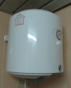
Stainless steel is used to make water heater. It has high rate of heat transfer and resistivity in corrosion.  In water heater mainly graham plate exchanger are used which is appropriate for flowing the higher temperature fluid.

Water heater
Water heater
Image Credit – Wikipedia Commons

Waste heat recovery:

Waste heat can be generated help of chillers, steam condenser, and many others process is used to making heat of air or water. High efficiency and lower temperature it helps to reduce energy cost.

Free cooling:

For the operation of free cooling chillers of the refrigeration system is shut down and helps to reducing the cost of plant utility. In the free cooling graham plate exchanger are used. During the free cooling process the air is pre cool by the help of cooling tower water.

Cooling tower isolation:

By the help of cooling tower isolation the cooling water is circulated in the buildings. . In the cooling tower isolation graham plate exchanger are used to minimize the turbulence of the water.

Cooling tower
Cooling tower
Image Credit – Wikipedia Commons

Plate and frame heat exchanger sizing:

For the measuring process of Plate and frame heat exchanger sizing is followed some steps. They are,

  1. Get the data of design
  2. Calculating the flux of the heat
  3. Calculating the needed number of thin plates
  4. Confirmation the size of the heat exchanger

Get the data of design:

At the beginning for calculating the size of the plate and frame heat exchanger the first step need to follow is get the data of design. The data which are should to follow to run this process is listed below,

  • Properties present in the fluids.
  • Temperature for each and every fluid in the outlet and inlet.
  • Pressure for the fluid in the inlet.
  • Allowable pressure drop.

Calculating the flux of the heat:

If flowrate of the flowing fluid, specific heat, inlet temperature, outlet temperature or either know the cold side or hot side then heat flux can be easily calculated.

With the help of the formula from which heat flux can be calculated is given below,

gif

Where,

mc = Mass flow rate on the lower temperature side in kg per second

Cpc= Specific heat on the lower temperature side

T2= Outlet temperature on the lower temperature side in Kelvin

T1= Inlet temperature on the lower temperature side in Kelvin

h = Mass flow rate on the higher temperature side in kg per second

Cph= Specific heat on the higher temperature side

T4 = Outlet temperature on the higher temperature side in Kelvin

T3 = Inlet temperature on the higher temperature side in Kelvin

By the help of Heat transfer coefficient heat flux can be determined.

gif

Where,

H = Overall heat exchange coefficient in kw.m2.K-1

S = Area of the heat exchanger in square meter

Calculating the needed number of thin plates:

The needed number of thin plates can determined using this formula,

N = S/s

Where,

N = Needed number of thin plates

S = Total area of the heat exchanger area in square meter

s = Size of a particular single plate in square meter

Confirmation the size of the heat exchanger:

Usingthe Nusselt number the size of the heat exchanger can be determined.

Where,

Nu = Nusselt number

a = Coefficient depending upon the corrugation of plate

Re = Reynolds number

b = Coefficient depending upon the corrugation of plate

Pr= Prandtl number

Prw = Prandtl number at the wall of the plate

Read more about Reynolds number : It’s 10+ Important facts

Plate and frame heat exchanger cleaning and maintenance:

Plate and frame heat exchanger cleaning and maintenance done in three steps. They are listed below,

  1. Scheduled maintenance
  2. Clean in place
  3. Manual maintenance

Scheduled maintenance:

The common process of maintaining Plate and frame heat exchanger cleaning and maintenance is scheduled maintenance. In this process scheduled and regularly maintain and cleaning the apparatus of the heat exchanger. These kinds of cleaning and maintenance process at least stay for six months.

Clean in place:

In this process periodically maintain and cleaning the apparatus of the heat exchanger. This kind of cleaning and maintenance process the plate not need to open it helps to drop excessive pressure inside the heat exchanger.

Manual maintenance:

In this process annually maintain and cleaning the apparatus of the heat exchanger. This kind of cleaning and maintenance process at least stays for more than one year.

Vapor Compression Cycle: What, How, Types, Working, Applications and Various Facts:

Refrigeration 1

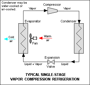
In this article ”Vapor compression cycle ” is discuss and vapor compression cycle related facts are also summarize briefly. The vapor compression cycle is commonly used is the system of refrigeration.

In the system of refrigeration which follows the cycle of thermodynamic, is used in a wide range. The energy of heat is transforming from a cold reservoir and after that transfer into a hot reservoir. In a closed cycle fluids is used and go through compression, condensation, and expansion, evaporation process.

What is vapor compression cycle?

The Vapor compression cycle is used in automobile and refrigeration industry. Chilling the storage food items and meat in the warehouses, oil refineries, chemical processing plants many others it is widely used.

The Vapor compression cycle explain as a liquid refrigerant is uses which rotate circularly in the system and works as a medium. The liquid refrigerant absorb the heat from any particular space where cooling is needed and also can remove heat from any particular space where heating is needed for the system.

Vapor compression cycle
Image – Vapor Compression Cycle
Image Credit – Wikipedia Commons

The vapor compression cycle is done in a closed cycle. In the system of vapor compression cycle the fluid which is work as a medium is actually a vapor. In a very speedy mode the fluid is evaporate and changes itself alternatively between the liquid phase and vapor or condenses inside of refrigerating plant.

Vapor compression cycle diagram:

The Vapor compression cycle the liquid refrigerant changes its state of phase for two times. In first step liquid refrigerant change itself liquid to vapor and in next step change itself vapor to liquid.

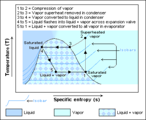
The Vapor compression cycle diagram can be explain as help of two diagrams which is given below,

Pressure – Volume diagram

512px Refrigeration PV diagram.svg
Image – Pressure – Volume diagram; Image Credit – Wikipedia

Temperature –Specific entropy diagram

RefrigerationTS
Image – Temperature –Specific entropy diagram;
Image Credit – Wikipedia

Vapor compression cycle process and working principle:

The Vapor compression cycle is a method which is most commonly used in various fields because its cost of charge is very low and the construction of the vapor compression cycle is quite easy to establish.

The cycle process of vapor compression in refrigeration system is working based on reverse Rankine cycle. The Vapor compression cycle process is proceeding in four steps. They are listed below,

Vapor Compression Cycle
Image – Vapor compression cycle process and working principle
Image Credit – Wikipedia Commons
  1. Compression
  2. Condensation
  3. Throttling
  4. Evaporation

In this below section the four steps are discusses,

Compression (Reversible adiabatic compression):

The refrigerant of vapor compression cycle at low temperature and pressure stretched from evaporator to compressor where the refrigerant is compressed isentropically. The pressure is rises from p1 to p2 and temperature is rises from T1 to T2. The total work done per kg of refrigerant happened during isentropic compression can be express as,

w = h2 – h1

Where,

h1 = Amount of enthalpy of vapor compression cycle in temperature T1, at the step of suction of compressor

h2 = Amount of enthalpy of vapor compression cycle in temperature T2, at the step of discharge of compressor.

Condensation (Constant pressure heat rejection):

The refrigerant of vapor compression cycle is passes through from compressor to condenser at high temperature and pressure. At constant pressure and temperature the refrigerant is completely condensed. The refrigerant changes its state from vapor to liquid.

Throttling (Reversible adiabatic expansion):

At high temperature and high pressure the refrigerant of vapor compression cycle is expanded through the process of throttling. That time the expansion valve is stays in low temperature and pressure. A little amount of liquid refrigerant is evaporating by the help of expansion valve and a huge amount of liquid refrigerant is vaporised by the help of evaporator.

Evaporation (Constant pressure heat addition):

The refrigerant mixture of vapor and liquid is completely evaporated and changed itself into vapor refrigerant. During this evaporation process the refrigerant is absorb latent heat which state is cool. The amount of latent heat absorption by the refrigerant in vapor cycle is known as Refrigerating effect.

Performance of vapour compression cycle in the refrigeration system:

The vapour compression cycle in the refrigeration system is working at evaporator in the law of Steady Flow Energy Equation,

h4 + Qe = h1 + 0

Qe = h1 – h4

The vapour compression cycle in the refrigeration system is working at condenser in the law of Steady Flow Energy Equation,

h2 + Qc = h3 + 0

Qc = h3 – h2

The vapour compression cycle in the refrigeration system is working at expansion valve in the law of Steady Flow Energy Equation,

h3 + Q = h4 + W

We know, value of Q and W is 0

So, we can write,

h3 = h4

Performance of vapour compression cycle in the refrigeration system is,

Output/Input = h1 – h4/h2 – h1

What is simple vapor compression cycle?

The simple vapor compression cycle air is used as a refrigerant and it is evaporate at very low temperature and low pressure. The mechanical energy is required to run the compressor of the system.

The simple vapor compression cycle can be explain as the heat engine which is works in reverse technically that can be known as Reverse Carnot engine. The simple vapor compression cycle transfer heat from lower temperature reservoir to higher temperature reservoir.

What is vapor compression cycle of a refrigeration system?

The vapor compression cycle of a refrigeration system is one of the most common used and popular refrigeration systems among the all refrigeration system. For both domestic and industrial purpose vapor compression cycle of a refrigeration system is used.

The vapor compression cycle of a refrigeration system is belong to the refrigeration cycle which is mainly general class type and in this system the refrigerant is undergoes phase chance , minimum during one process. The cycle is working in a closed system and refrigerant is moves in a circular motion.

In vapor compression cycle NH­3, R – 12, R- 11 refrigerant are uses. The vapor compression cycle of a refrigeration system consists of refrigerant compressor, liquid compressor, liquid receiver, evaporator and expansion valve which are known as refrigerant control valve.

Vapor absorption refrigeration cycle:

The vapor absorption refrigeration cycle can work easily where high power is not available. The main difference between vapor compression cycle and vapor absorption refrigeration cycle is compressor is replaced.

In the vapor absorption refrigeration cycle lowering the temperature of the system which is done in a closed system, refrigerant work as medium and removing unwanted heat from any particular space of the system and after removing transfer the heat where temperature is lower in the refrigeration system.

Read more about Saturated Suction Temperature : Need to know Critical Facts

In the vapor absorption refrigeration cycle generator, pressure reducing valve, expansion valve, condenser pump and absorber is used.  Ammonia is use in the system as a refrigerant and the mixture of ammonia, lithium bromide, water and water is used as an absorbent.

Ideal vapor compression cycle:

Ideal vapor compression refrigeration cycle system at first refrigerant enter into the compressor as a saturated vapor after that the refrigerant became cool to the liquid state of saturated inside the condenser. When the throttling process is happened in the evaporator vapour and pressure is absorb in the refrigerate space.

Simple vapor compression cycle:

Simple vapor compression cycle refrigeration cycle systems at first refrigerant enter into the compressor as a vapor at lower pressure. After that the refrigerant became superheated at higher pressure inside the condenser. When the throttling process is happened in the heat is release and enters to next process of the cycle.

Read more about Superheat Hvac : IT’S IMPORTANT CONCEPT AND 3 FAQs

Actual vapor compression cycle:

Actual vapor compression cycle refrigeration cycle is not same process as the theoretical vapor cycle of process. In the actual vapor compression cycle loss and unavoidable vapor is present.  The refrigerant leaves the evaporator in the state of superheat.

Read more about Superheat Refrigeration : Its All Important 4 notes

Vapor absorption cycle:

Vapor absorption cycle in the refrigeration system can be describe as refrigerant condensed in the condenser and evaporate at evaporator. In this all refrigeration system process are present such as compression, condensation and expansion evaporation. As a refrigerant lithium bromide, water or ammonia can be used.

Vapor absorption cycle applications:

Application of vapor absorption cycle in refrigeration system is given below,

Domestic refrigeration:

 In dwelling units food is storage in domestic refrigeration.

Cold storage and Food processing:

For processing, preserving and storage food items from its origin of source to the distribution point of the wholesale distributions.

Commercial refrigeration:

Displaying and holding fresh and frozen food items in retain outlet.

Medical refrigeration:

For keeping the medicine in right temperature medical refrigeration is used.

Electronic cooling:

For controlling temperature in large computers, CMOS circuit (Complementary metal–oxide–semiconductor)electronic cooling is used.

Vapor absorption cycle working principle:

The Vapor absorption cycle working principle is summarize in below,

  1. At beginning of the process vapour comes from evaporator and then go to absorber and vapour is absorbed in water.
  2. During the process of absorbing latent heat and heat of mixing is emitted.
  3. Cooling process is done by the absorber to keep the temperature lower in the system.
  4. Absorbing capacity is increases when the absorber is in lower temperature.
  5. Strong aqua mixture of ammonia and water is comes from the absorber and go to the top of the analyzer with the help of pump through aqua heat exchanger.
  6. By the generator the aqua falls mixture is sent to analyzer. In the generator higher temperature is present for this reason low boiling ammonia easily can be separate from the mixture.
  7. The heating process of the generator can be done with the help of solar energy, steam energy or electric energy. In this time ammonia vapour is raises by the analyzer.
  8. During this process wet vapour became dry vapour and sent to the condenser by rectifier.
  9. Water is separated. After separation water is again back to generator this known as Drip. Anhydrous ammonia vapour only goes to the condenser. Liquid ammonia go from condenser to evaporator through the valve of expansion for continue the cycle.
  10. When the aqua mixture is hot it became weaker and comes to evaporator of the system through the heat exchanger. The weak hot aqua again absorbs the vapour of ammonia and cycle stays in continue.
  11. Heat exchanger of the aqua heat the strong aqua mixture and pass to the generator in this process heat is reduced in the heating materials in the generator.

Vapor absorption cycle processes:

Vapor absorption cycle process is done by four steps.

Compression process:

In first of the vapor absorption cycle process compression process is done. In this process vapour stays at very low pressure and temperature.  The vapour is enters to the compressor when it is compressed subsequently and isentropically. After this both temperature and pressure are increases.

Condensation process:

After completing the process in compressor vapour enter to condenser. The vapour is condensed in the high pressure and goes to the receiver tank.

Expansion process:

After completing the process in condenser vapour enter to expansion valve from receiver tank. The throttling process is done in the low pressure and low temperature.

Vaporization process:

After completing the process in expansion valve vapour enter to evaporator. In the evaporator the vapour is extracts heat and circulating fluid in the surrounding environment and in lower pressure vapour is vaporized.

If without throttling expansion is takes place then the level of temperature will be drop in very low temperature and undergoes sensible heat, latent heat to particularly reach to stage of evaporation.

Difference between vapor compression and absorption cycle:

The vital difference between vapor compression and absorption cycle is Coefficient of performance vapor compression is high and for vapor absorption refrigeration cycle Coefficient of performance is low.

In below briefly the Difference between vapor compression and absorption cycle is given,

Particular Vapor compression cycle of a refrigeration system Vapour absorption refrigeration cycle of a refrigeration system
Coefficient of performance(COP) High, range is about 0.3 Low, range is about 0.6
Noise Very high operation Quiet operation
Wear and Tear High, because moving parts are more present in the system of the compression. Low, because moving parts are less present in the system of the absorption.
Bulkiness More less More
Presence of shelter Cannot situated in outside of the system without shelter Can be situated in outside of the system without shelter
Affected by loads Too much Reduction of load no effect
Leakage possibility More Less
Charging of refrigerant Simple Complicated
Working of high grade energy High, electrical energy is needed to precede the operation. Low, electrical energy is not needed to precede the operation, by the help of Ignition combustion engine, process heat or kerosene lamp the vapour absorption refrigeration cycle of a refrigeration system can work.
Operating cost High Less
Capacity Less, upto 1000 tons More, above 1000 tons
Suitable refrigerant NH­_3, R – 12, R- 11 Ammonia
Energy supplied as input Mechanical Heat energy
Condition of refrigerant Compressed Absorbed and heated.
Supply of energy Low High
Maintenance cost High Low
Pressure High Low
Work capacity Limited Large

Frequent Asked Question:-

Question: Write down the advantages of Vapor Compression refrigeration cycle.

Solution: The advantages of Vapor Compression refrigeration cycle is listed below,

  1. Coefficient of performance is too high.
  2. Size is not too big for this reason installation is easy.
  3. Running cost is low.
  4. Temperature can be easily handled by the help of regulating expansion valve.
  5. Evaporator size is not big.

Question: Write down the disadvantages of Vapor Compression refrigeration cycle.

Solution: The disadvantages of Vapor Compression refrigeration cycle is listed below,

  1. The refrigerants which are used they are toxic.
  2. Initial cost is high.
  3. Leakage is present.

Gate-Level Power Optimization Techniques: A Comprehensive Playbook

gate level power optimization techniques

In the ever-evolving world of electronics, power optimization has become a critical concern, particularly at the gate level. Power consumption is a crucial factor that impacts the performance, efficiency, and battery life of electronic devices. To address this challenge, engineers have developed a range of gate-level power optimization techniques that focus on reducing power by … Read more

Numeric Problems on Logic Gate Fan-Out: A Comprehensive Guide

numeric problems on logic gate fan out

Fan-out is a crucial parameter in digital circuitry that determines the maximum number of digital inputs that the output of a single logic gate can drive without disrupting the circuit’s operations. Understanding and calculating the fan-out of logic gates is essential for designing reliable and efficient digital systems. In this comprehensive guide, we will delve … Read more

High Limit Switch Furnace: Several Facts And FAQs

furnace limit switch

In this article we will discuss about the High Limit Switch Furnace. To operate a residential gas furnace safely and efficiently the use of a High Limit Switch is essential.

High Limit Switch, also known a “Fan Limit Switch” or simply “Limit Switch” plays an important role from safety point of view. The main function of a Limit Switch is to sense the temperature in the air plenum of the gas furnace and shuts off the burner as temperature goes to a limit which may cause a dangerous or uncomfortable condition. 

Why Does High Limit Switch Trip?

The suspected reason for High Limit Switch tripping is lack of airflow through the furnace, due to which temperature becomes high and the Limit Switch trips off.

An airflow issue through the furnace generally leads to Limit Switch tripping. Lots of reasons are there which prevent an adequate airflow throughout the system.

  • Air Filter: A dirty filter is one of the most common issue which prevents the flow of air through the furnace, resulting a very hot heat exchanger causing tripping of the Limit Switch. On the body of the air filter certain arrows are marked for the direction of air flow, these arrows must be followed properly to avoid any kind of air blockage.
  • Blocked Register: Through the registers, air flows out of a furnace, therefore the register should not be blocked to ensure proper movement of air.
  • Exhaust Vent: After the burning of gases inside the furnace, the exhaust gases should be vented out. The blockage of exhaust vent may cause overheating.
  • Blower Motor: If the blower motor is not working efficiently and air flow is not fast enough, then the heat exchanger get overheated.
  • Blocked ‘A’ Coil : ‘A’ Coil used to flow air from the system is sometimes clogged with debris.
  • Defective Limit Switch: Sometimes the Limit Switch itself going bad, this may be another reason for tripping. Then it has to be replaced or repaired for proper and safe functioning of the furnace.

Open High Limit Switch Furnace

A Furnace High Limit Switch is designed in such a manner so that it can activate and deactivate the furnace blower assembly as per the requirement.

Open High Limit Switch Furnace indicates the heating system turns off the fuel supply to prevent the overheating which may damage the furnace as well as create a dangerous situation inside the residence.

High Limit Switch Location

High Limit Switch Furnace is a small but very essential device used in air furnaces powered by natural gas, LP or heating oil.  

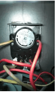
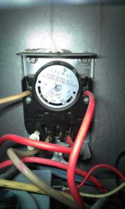
To detect the furnace Fan Limit Switch, cabinet cover should be removed. Generally it is attached to the plenum of the furnace above the combustion chamber or heat exchanger. Location of the Switch may vary as per the make and model of the Furnace.

high limit switch furnace
Components of A Gas Furnace; Image credit:flickr

How Does A Furnace High Limit Switch Work?

Furnace High Limit Switch protects the furnace as well as the home or business area by automatically bringing the temperature of the furnace down when it goes too high.

Acting as the key component of the furnace safety system, the two main functions of the High Limit Switch are:

  • Regulation of Fan Motor: It gives the blower fan an indication when to turn on and off. When the air is heated enough, it senses the supply air temperature and tells the fan to turn on in order to circulate hot air into the home. It allows the blower to keep on running until all heated air is distributed inside the residence completely.
  • Prevents from Overheating: It also identifies the supply air temperature, when the supply air temperature is too high, the components inside the furnace may get damaged. At this moment, the Limit Switch trips to shut down the system and stops furnace functions to control the temperature. In most extreme cases overheating may lead to fire hazards.
8652050394 4e6dd82218 b
Furnace High Limit Switch; Image Credit: Flickr

Bypass High Limit Switch Furnace

It is advice able that Fan Limit Switch or Limit Switch should be bypassed only for a temporary basis.

Limit Switch should be bypassed only for an essential reason like troubleshooting or testing purpose. A Furnace High Limit Switch acts as an essential part during the operation of a furnace by regulating the temperature, thereby it prevents the damages that may occur to the internal components of the furnace as well as maintain safety of the human being.

If we run a residential gas furnace without the Limit Switch for a long time, heat exchanger may damage and toxic gases may enter the living area of the residence. 

High Limit Switch Furnace reset

After detecting the problem associated with High Limit Switch and resolving it, the Limit Switch has to be reset for normal functioning of the furnace.

The steps to be followed for resetting the High Limit Switch Furnace are :

  • At the beginning we have to close the gas valve and cut off the power supply to deactivate the system. This step is done completely for safety purpose.
  • After that panel should be opened with the help of a screw driver to find the furnace’s heating duct.
  • Identify the white or silver Limit Switch, remove the cover to see the body of the switch with two metal arms.
  • These two arms are responsible for the high and low temperature range of the furnace.We have to identify the component in between these two arms which control the fan.
  • Fix the temperature of the central component at approximately 105-115 degrees Fahrenheit. Try to ensure the fan switches off and on at accurate time.
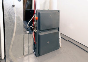
  • Now set the temperature on the left component at around 90 degree Fahrenheit, which will give indication to the left arm to stop blowing cold air when it reaches 90 degrees ,similarly set right arm at 200 degree Fahrenheit, which indicates the furnace to shut off when the burner reaches this temperature.
istockphoto 1344298893 170667a
A home high energy efficient furnace in a basement; Image Credit: Unsplash

How to Replace?

The Furnace High Limit Switch helps to ensure your safety and the comfort of your home.

The steps to be followed to replace a defective High Limit Switch Furnace are:

  1. At first we have to deactivate the furnace using service switch or circuit breaker to avoid any kind of accident.
  2. After that replace the old one and fix the new Limit Switch by wiring it exactly the old Switch. It is quite simple since it has only two wires coming off and two screws are there to hold it in place. For further issues the instruction manual provided along with the Limit Switch can be followed.
  3. After setting up the new Switch, furnace can be activated and regulate the thermostat to get accurate signs of the heating process of the furnace. Sufficient amount of hot air through the vent will justify smooth replacement of the Limit Switch.

How to Test High Limit Switch Furnace?

After checking all the possible reason of tripping up of the High Limit Switch Furnace and it is noticed that blower motor is working, filter is clean enough then the Limit Switch is need to be tested.

Testing of High Limit Switch Furnace is a DIY task which can be easily done with the help of a screwdriver and a multi-meter. Steps Followed to test High Limit Switch Furnace are:

  • First of all deactivate the system either by turning off the serviceman switch or shutting the power off at the breaker panel.
  • Opening the panel and identify the white or silver High Limit Switch.
  • Disconnect the wires attached to the switch, try to remember the connection to reconnect them.
  • Now with the help of a multi-meter, test if there is continuity between the two arms.

If the High Limit Switch Furnace is faulty, replace it with a new one.

In continuity test of a High Limit Switch Furnace, a multi-meter set is used to measure resistance in ohms, small electric current is sent between the switch terminals and measures the resistance between them.

Generally two possible rest results are: Zero (or near to zero),indicating switch is closed and current is flowing. Another possibility is Very High or Infinite, indicating the switch is open.

When Do You Use a Rectifier Diode: A Comprehensive Guide to Understanding Its Applications

when do you use a rectifier diode a guide to understanding its applications

Rectifier diodes are essential components in numerous electronic circuits, playing a crucial role in converting alternating current (AC) to direct current (DC). These specialized diodes allow current to flow in only one direction, from the anode to the cathode, enabling the rectification process that is fundamental to power supply design and various other applications. In … Read more