MOS Transistor: 3 Important Facts You Should Know

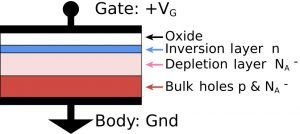
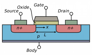
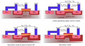
1920px MOSFET functioning.svg 300x162 1

Topic of Discussion: MOS Transistor

What is MOS Transistor?

A Metal-Oxide-Semiconductor or ‘MOS’ transistor is recognized for its operation as an ideal switch operation.  A MOS transistor chip performs as a reliable current and capacitor of the transistors and its wires.
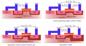
1920px MOSFET functioning.svg
a MOS structure in Inversion, Saturation and Depletion region, Image credit – Olivier Deleage and Peter Scott, MOSFET functioningCC BY-SA 3.0

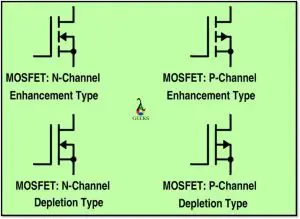
In the figure below, we can see some regular schematics of MOS transistors that are used commonly
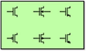
MOS transistors
regular schematics of MOS transistors

We typically use the different terminal symbols i.e., figure when the body along with the substrate or the well-connection needs to be shown.

Working Principle of MOS Transistor:

For being a majority carrier device, a MOS transistor carries the current between its source and drain. This transistor gets regulated with a regular voltage applied to the gate of the respective MOS. In an n-MOS transistor, the electrons act as a the majority carrier while in a p-MOS type, Holes is acts as majority carriers. A MOS transistor is examined with an isolated MOS structure with a gate and body included to know about its properties or behavior’s figure below gives a simple structure of MOS. The top most layer of the MOS structure is made of a conductor.

This is very good for carrying currents for any charge; which is acknowledged as the gate. The transistors which were made at the very beginning, used metal gates; with the up growing time period, the transistor gates were changed and polysilicon is being used. The intermediate mid-layer of a MOS is made of a thin insulating film of silicon oxide which is usually identified as the gate oxide. The layer at the lower level is doped with silicone.

If we apply a negative voltage in the gate, a negative charge on the gate is produced. Beyond the gate, the holes are attracted toward the region as the mobility carriers are charged with positive energy. This is called the accumulation mode.

In figure (b), a A very minimal amount of voltage is supplied to the gate, which we get from a positive charge on the gate. To form a depletion region, the holes of the body which are generated from repulsion, get accumulated under the gate.

In figure (c), Threshold Voltage Vt is supplied and few electrons gets attached to that area.

Inversion Layer:

The conductive layer of the electrons in the p-type body is considered as an the ‘inversion layer’.

Here, the threshold voltage depends on two parameters, they are –  1. MOS’s dopants 2. Oxide layer’s thickness. It is regularly positive but they also can be made into negative ones. The nMOS transistor has piles of MOS between both the n-type regions called the source and the drain.

At this point, the gate-to-source voltage Vgs < the threshold voltage (Vt). The source and drain are having no of free electron in both sides. When the source is not working i.e., in ground state, the junctions are said to be reverse-biased, so no current flows. When the transistor is said to be OFF, this mode of operation is called cut-off.

the current is 0 if we compare it with an ON-transistor. The gate voltage is higher than the threshold voltage. Now if an inversion region of electrons which are the channel, makes a bridge between the source and drain and create a conductive path and turns the transistor ON. The increase in the number of total carriers and the conductivity increases are proportionate to each other with respect to the applied gate voltage.

The drain voltage – Source voltage is given as:

 VDS = Vgs – Vgd . When, VDS = 0 (i.e., Vgs = Vgd),

there is no such electric field exists to produce current from drain to source.
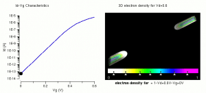
Threshold formation nowatermark 1
 Inversion channel and attainment of threshold vol­tage (IV), Image Credit – Saumitra R Mehrotra & Gerhard Klimeck, modified by ZephyrisThreshold formation nowatermark, marked as public domain, more details on Wikimedia Commons

When, The voltage (Vds ) is applied to the drain, and the current Ids carries through the channel of drain to the source. If Vds becomes larger than that Vgd < Vt, the channel doesn’t seem to have any change near the drain and hence it is in off state. Even after this, the conduction is being continued with the help of the drifted electron which is generated by the +ve voltage.

 When the electrons reached to the termination of the channel, the depletion region adjoining the drain gets accelerated in the direction of it. The injected electrons accelerate this process.

Saturation Mode:

In this mode, the current Ids is controlled by the gate voltage and gets terminated by the drain only when it reaches beyond the drain voltage.

V-I Characteristics of MOS Transistor

The V-I characteristics of MOS transistor has three regions of operation:

  • The Cut-off or sub-threshold region.
  • The Linear region.
  • The Saturation region.

The length of channel in an n-MOS transistor is lengthier and the electric field amongst the source to drain is comparatively low. The channel is generally identified as the ‘long-channel’, ideal, 1st order, or Shockley model while characterized as a figure.

The long-channel model represents a current that carries through an OFF transistor. It is very low or 0.  The gate attracts carriers to build a channel in its OFF state (Vgs> Vt). At the source to drain region, the electrons keep flowing at a uniform speed.

Charge of the capacitor plate is given by – Q = CV.

Thus, the charge in the channel Qchannel is

                                    Qchannel = Cg(Vgc – Vt)
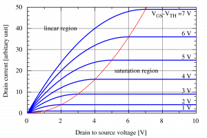
1920px IvsV mosfet.svg
Image Credit – User:CyrilBIvsV mosfetCC BY-SA 3.0

The above graph shows the I-V characteristics for the transistor.

 In the particular graph, the current which flows is ‘0’ for gate voltages underneath Vt. The current has increasing when the gate voltage increases accordingly linearly with V­ds for small Vds. As Vds approaches the saturation point Vdsat = VGT, current declines and eventually turn out to be independent.

 The pMOS transistors behave in a reverse way than the n-MOS transistor  so all voltages and currents are negative here.Here the current flows from source to drain and the fluidity of holes in a silicon is usually lower than that of the electrons.

 So, a p-MOS transistor produces less current than n-MOS transistor of same size and features. Here µn and µp = mobility of electrons and of holes in n-MOS and p-MOS transistors, respectively. The mobility ratio µnp lies between 2–3. The p-MOS transistors have the identical geometry like a nMOS.

For more about MOSFET and others electronics related article  click here
CMOS Amplifier: 5 Important Explanations

CMOS Amplifier 300x60 1

Topic of Discussion: CMOS Amplifier

  • What is CMOS ?
  • What is CMOS Amplifier ?
  • Input Offset voltage
  • Different parameters in CMOS amplifier
  • Applications of  CMOS  Amplifier

What is CMOS ?

CMOS:

CMOS is acronym of Complementary Metal Oxide Semiconductors. It is one of the types of Metal oxide Field Effect Transistor and it is a unipolar device unlike BJTs.

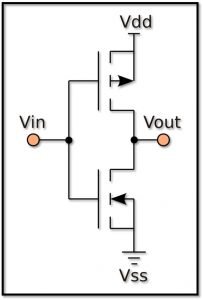
CMOS amplifier: CMOS inverter
CMOS inverter

What is a CMOS Amplifier ?

CMOS Amplifier:

CMOS amplifiers (complementary metal–oxide–semiconductor amplifiers) are universal analog circuits utilized in personal computer, laptops, audiovisual device, mobilephones, cameras, communication systems, different biomedical applications, to many more other applications. In high performing CMOS amplifier circuitry, transistors are generaly used. Transistor not only utilzed to amplify the signals but those are also utilized as active load to attain high gain and output swing in comparison to resistive loading blocks.

The above figure shows a two stage CMOS Amplifier.

Some of the critical parameters which represents the amplifiers are – 1. Range of the supplied voltage, 2. Response to frequencies, 3. Response to the Noises, etc.

Input Voltage Range:

The range designates a “permissible” I/P voltage that will generate a linear, non-distorted O/P signal.

                                          VDS>VGS – VT

VG is the input voltage, VD is VDD -VSAT for PMOS.

From the above explanation, the input voltage is able to swipe to some degree above the voltage VDD. The M15 and M16 are constructed to oppose to that current direction of M14. Nonetheless, VDM12 is not equal to VDM14.

Signal Path of CMOS Amplifier:

Signal-path represents the path through which the signal reaches to the output from the input. The signal path employed to investigate the freq-response, stability, and many more factors.

As the standard CS amplifier has high gain, the Miller effect will increase the total input capacitance. Any capacitance between output and input can be seen as capacitance at the input to the ground with the multiplication of (1 + Gain).

Load in CMOS Amplifier:

We can observe two varieties of active load in CMOS Amplifier: The diode connected MOS or current source MOS.

  1. It represents the output associated with a source of current. The current source acts as ‘Load’ for the output.
  2. By reason of Vgs of the active load is constant. Resistance value is r0 = 1/λId, where Id is drain current. The low frequency or direct current (DC) gain,

                        Av = gmn (roM16 // r0casp) gM17 (r0M18 // r0M17)

Typical load problem:

• Buffer configuration is a severe test for instability. It is found that a need of having a greater compensation capacitor for this purpose.

• It cannot drive a small load resistor.

CMOS Amplifier Parameters:

Input Offset:

The offset voltage is Vref – VI

The offset voltage of the amplifier has presented in above figure. This is measured from the disparities by taking considerations of paramter such as threshold voltage, load resistance, etc.

Common Mode Rejection Ratio (CMRR):

“CMRR is given by the ratio of the gain of the amplifier in differential mode to the gain of the amplifier in common mode.”

Power Supply Rejection Ratio(PSRR):

Power Supply Rejection Ratio or PSRR is given by the ratio of Output voltage to the input voltage. PSRR describe the noise rejection of CMOS amplifier.  Typical method to improves the power supply rejection ratio is generally by by means of a cascode current source or sink (this is because of high output resistance value).

Slew Rate and Settling Rate:

  • High slew rate
  • Small compensation capacitorIncrease the operating current

Settling time is equivalent to Tsettling parameter and

Slew Rate = Vidmax

Noise:

For 1 μA, 7.8 × 10¹² electrons passing every second will generate a noise of 7800 Giga Hertz.

1. The higher input transistor is required to reduce the noise level.

2. Increase in operating current is also required.

3. White and short noise  is mostly constant during the total operation

4. Flicker noise

Compensation in Amplifier:

Compensation is required to ensure stability in opamp. A CMOS Amplifier, loop-gain and phase are the prameter generally specify the Amplifier’s stability. The Op-Amp is generally constructed in a closed-looped for gain and phase analysis puropse. Suitable capacitance, resistance and biasing is also required for the compensation of amplifier.

Uses of CMOS Amplifier:

  • This complementary metal–oxide–semiconductor amplifiers are utilized in personal different electronics consumer products such as computer, laptops, audiovisual device, mobile phones, cameras etc.
  • These are one of the important component of telecom appliance
  • Different biomedical applications utilized these type of amplifier nowadays. There are many more other applications of CMOS amplifier and list is increasing.

For more about MOSFET basics and others electronics related article  click here

Read more about Log & Antilog Amplifier.

Introduction To MOSFET: 11 Important Explanations

MOSFET 1024x748 1 300x219 1

Topic of Discussion: MOSFET basics

What is MOSFET?

Definition of MOSFET:

The Metal-oxide-semiconductor field-effect-transistor (MOSFET), is a form of insulated gate field effect transistor that is made-up by the controllable oxidised silicon based semiconductors”.

Different types of MOS:

  • ·        P Channel MOSFET
  • ·        N Channel MOSFET

Different types of MOSFET devices:

  • ·        Enhancement Mode MOSFET
  • ·        Depletion Mode MOSFET

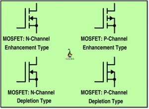
MOSFET Symbol

MOSFET 1024x748 1
MOSFET basics : MOSFET Symbol

Working Principle of MOSFET:

MOSFET Basics

A FET is worked as a conductive  semiconductor channel with 2 contacts – the ‘SOURCE ‘ and the DRAIN. The GATE juntion might be comprehended as a  2 -terminal circuitry as a MOS structure working as a rectifing reverse biasing mode. Usually, the GATE  impedance is higher in classic working situations.

The FETs as per these standards are typically MOSFET, JFET,  metal-semiconductor FET (MESFET), and heterostructure FET. Out of these FET, MOSFET is one of the significant one and commonly utilized for various applications.

In a silicon  based MOSFET, the GATE terminal is normally insulated by a specific SiO2 layer. The charge carriers of the conductive channel develop an opposite charge,  e-  in that case, p-type substrate for an n-channel and ‘holes’ for n-type substrate  for the p-channel. This will induced in the semiconductor at the silicon-insulator edge by the applied volt in GATE terminal. The e- will enter and depart the channel at n+ source and drain terminals cotacts for an n-channel metal-oxide-semiconductor field-effect-transistor.  This will be  p+ contacts during the  p-type Metal-oxide-semiconductor field-effect-transistor.

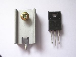
Mosfet chip
MOSFET basics : A typical MOSFET chip with heat sink
Image credit: WilltronTransistor y disipadorCC BY-SA 3.0

MOSFET layer

MOSFET layer 1
MOSFET basics : MOSFET layers in Metal–oxide–semiconductor structure on p-type silicon Image Credit :MOS_Capacitor.pngBrews ohare derivative work: Fred the Oyster (talk), MOS CapacitorCC BY-SA 3.0

Implementation of MOSFET:

Metal-oxide-semiconductor field-effect-transistors are working as discretized circuit and also as an active element. At the present time, these circuits are scaled down into the deep sub micro meter range. At the moment, the standard 0.13-µicro meter standard technology node CMOS is utilized for VLSI technology and, in future 0.1-µicro meter technology will be existing, with a certain upgradation of speed and integration range.

CMOS technology associates with the n-channel and p-channel Metal-oxide-semiconductor field-effect-transistor to consume very less power without constraining the performing speed. New SOI technology accomplish three dimentional integration with multiple layers, with a electrifying increase in integration stupidity. Novel and enriched structures and the combination of Bi-CMOS technology possibly will lead to further enhancements. One of the emerging areas of CMOS is across a variability of applications from audio device of  kHz range to modern wireless application operated at GHz range.

MOS
MOSFET basics : MOSFET Regions, Image Credit – Cyril BUTTAY, Lateral mosfetCC BY-SA 3.0

Short channel Effect in MOSFET:

Usually FET sizes are assessed by the device aspect ratio. This is the ratio of the gate length in respect of active vertical measurement of FET. The perpendicular dimension for the oxide breadth is measured as parameter di, the source and drain junction depths is considered as parameter rj.  The source and drain junction depletion depths are diefined by the parameter Ws and Wd respectively. The low aspect ratio is identical with short channel characteristics.

                 L<Lmin(µm) = 0.4[rj(µm)di(Å)(Wd + Ws)2(µm2)]1/3

When L is less than Lmin,.

The Metal-oxide-semiconductor field-effect-transistor threshold voltage is consederd as VT . This voltage will be impacted in a number of ways as a result of gate control. Generally, depletion charges near-source and drain are under the common control. The charge will develop a moderately higher portion of the GATE charge carrier. The depletion charge near drain inflates with increasing drain-source biasing voltage, causing in an additional VDS-dependent shift in threshold voltage .

The VT is a sort of barrier combined with carrier injected from the source to channel direction. This barrier is considerably adjusted by use of a drain biasing voltage. In n-channel Field effect transistors, the drain is dropping the threshold voltage and a concurrent rise in the threshold current with growing VDS.

High Field Effect of MOSFET:

In case of drain-source biasing of a Field effect transistor grow towards the drain saturation voltage which termed as ‘VSAT’ wherever a range of higher electric field  is created near by  drain. The  velocity of e-  in that region will saturates. In saturation region, the length considered as ∆L of the high-field  increases in the course of the source with growing VDS, and the performs as if the in effect channel length is decreased  by the parameter ∆L. This phenomenon is entitled as the Channel-length modulation  or  simply termed as CLM in the MOSFET basics. The subsequent simplified manifestation links of VDS to the length of the saturated region is as follows:

                                             VDS = VP + Vα [exp(l/l)-1]]

wherever Vp, Vα, and l are parameters interrelated to the e- saturation velocity. Here, Vp is the potential at the point of saturation in the channel, that is commonly estimated by the parameter VSAT.  Ths agreement is obtained amongst the potential summary which is acquired from the 2D simulation model of an N-channel MOSFET.

Hot Carrier Effects:

Hot-carrier effect is one of  the most important concerns when shrinking FET size into the deep sub micrometre.It decreases the channel length while maintaining high power supply levels. These are increased  to electric field strengths and reasons  of speed up and heating the charged carriers. A comprehensive model for the substrate current is very difficult for circuit-level modelling.

Temperature Dependence and Self-Heating:

The MOSFET basics circuitry is functional in different environs, including different temperatures ranges. Heat created from power dissipation in a circuitry is also significant and the increase in temperature for circuit design is also needed to be considered. The design turns out to be more and more difficult as the device size is becoming very small and power dissipation are increasing with different mode of operation. The thermal characteristics are extensively studied by various models.

For more about MOSFET basics and others electronics related article  click here
CMOS Image Sensor: 5 Complete Quick Facts

Picture1 300x252 1

CONTENTS

  • What is CMOS image sensor ?
  • Different types
  • Working principle
  • Designing
  • Architecture

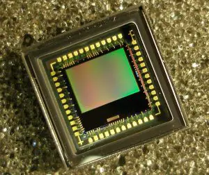
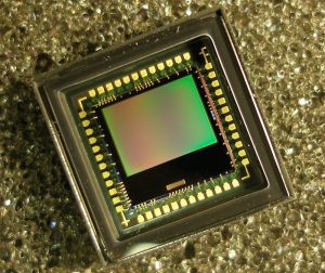
Cover Image By – Zach DischnerNerd-Tographer Desk Ornament (9698639550)CC BY 2.0

What is CMOS image sensor ?

CMOS Image and Colour Sensor:

Complementary metal-oxide semiconductor (CMOS) image sensors is comprised of photodiodes with and mixed-signal circuits  ahving capability to amplify small photocurrents into digital signals. The CMOS image sensor is one of the best cricuitry for multiple photography related  applications, i.e digital video cameras, photo scanners, Xerox machine, printing and various others. CMOS are nowadays utilized because of its multiple usage and it’s simple fabrications technique even with constain of sensivity in comparison with CCD.

Three types of the topology of CMOS colour sensors are discussed, namely the transimpedance amplifier (TIA), light to frequency converter, and light integrating.

Picture1
CMOS image sensor
Image Credit : Filya1MatrixwCC BY-SA 3.0

Working Principle of CMOS Image Sensor:

In general, four types of procedures are available

  • Standard CMOS,
  • Analog-mixed-signal CMOS,
  • Digital CMOS, and
  • CMOS image sensor processes.

The most obvious difference between this process and the other processes is the availability of photo devices, such as a pinned photodiode. The advantages of smaller dimension technology are smaller pixel, high spatial resolution, and lower power consumption. A technology lower than 100 nm requires modification to the fabrication process (not following the digital road map) and pixel architecture.

Fundamental parameters such as leakage current (will affect the sensitivity to the light) and operation voltage (will affect dynamic range, i.e., the saturation, a pinned photodiode is most likely not going to work at a low voltage are very important when a process is selected for CIS development. Because of these limitations, a new circuit technique is introduced:

1.  An old circuit, such as a standard pixel circuit cannot be used when using 0.1 micron and lower. This is due to the topology which requires high voltage; because the maximum supply voltage is now lower.

2. Calibration circuit and cancellation circuit are normally employed to reduce noises.

In order to increase the resolution into multi-megapixel and hundreds of frame rate, lower dimension technology is normally chosen. Evidently, it has been reported that 0.13 micron and 0.18 micron are good enough to achieve good imaging performance.

These modifications of the CMOS process have started at 0.25 micron and below to improve their imaging characteristics. As process scaling is going to be much lower than 0.25 micron and below, several fundamental parameters are degraded, namely, photo responsivity and dark current. Therefore, the modifications are focused on mitigating these parameter degradations. System requirements (such as supply voltage and temperature) are also one of the criteria in selecting a suitable process.

The price of tool and development costs will also determine the process selection.

Photo Detetor Devices

The typical photo detector devices are photodiode and phototransistor. Typical photodiode devices are N+/Psub, P+/N_well, N_well/Psub, and P+/N_well/Psub (back-to-back diode) [9]. Phototransistor devices are P+/n_well/Psub (vertical transistor), P+/N_well/P+ (lateral transistor), and N_well/gate (tied phototransistor).

These standard photo devices still require a micro lens and colour filter array. The quantum efficiency of photodiodes in a standard CMOS is usually below 0.3.

The devices which are normally developed for the modified CMOS process are a photogate, pinned photodiode, and amorphous silicon diode. These devices will improve the sensitivity of the CIS. A pinned photodiode, which has a low dark current, offers good imaging characteristics for the CIS.

The photodevices exhibit the parasitic capacitance, which should be considered during the design process. An example of the parasitic capacitance of N_well/Psub is:

                       Cphoto = (capacitance per area) × photodevice area.

Design Methodology of CMOS Image Sensors:

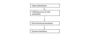
The typical design flow of the CMOS image sensor is shown below.

Typical design flow of the CMOS image sensor

A wave propagation simulation can be done for optics simulation. Commercially available technology computer-aided design tools, such as from Synopsys and Silvaco, can be used to simulate the process or technology of the photodevices. There is a work, (mixed-mode simulation) that combines the technology computer-aided design and pixel-level simulation.

There are many electronic design automation tools available for pixel electrical simulation, these electronic design automation tools are similar to any integrated circuit (IC) design tool, such as spectre, SPICE, Verilog-A, and Verilog. These tools may be time consuming  sometimes if the number of pixels is large.

Indeed, if large pixels together with the deep submicron process are required, more capital has to be provided (cost of tools are more expensive for very deep submicron, especially below 90 nm). Even though the CMOS foundry provides the models for supported design tools, sometimes designers still have to model the sub-block on their own to suit the CIS specification. This can speed up the pixel electrical simulation time, however, this will degrade the accuracy. For system simulation, VHDL-AMS, System-C, or MATLAB can be used to predict the overall function and performance.

CMOS Image Sensor Architecture:

Pixel Level ADC – A digital pixel sensor (DPS) offers a wide dynamic range. The DPS converts the analog values to a digital signa within the pixel range. The processing can also be done at the pixel level.

640px Digital Position Sensitive Device.svg
Digital positive Sensitive device, Image Credit – Georg Wiora (Dr. Schorsch), Digital Position Sensitive DeviceCC BY-SA 3.0

Chip Level ADC – Chip-level ADC or sometimes matrix-level ADC is depicted in Figure below.

chip level
Matrix-level ADC

The ADC for this topology has to be very fast, this topology would also consume a very high current. The ADC type suitable for the CIS topology is pipelined ADC. However, successive approximation register (SAR) and flash type ADC have also been reported in the CIS design. The balance of  necessary overall power intake and speed of operation is therefore essential.

Digital Pixel Sensor – The DPS concept is similar to the solution used in the CMOS neuron-stimulus chip. The DPS in number is found useful for on-chip compression. The photodiode is used to discharge the input capacitance of the comparator and photodiode itself. It will be discharged proportionally to the light intensity. When this reaches the threshold, the   comparator’s O/P will be triggered.

Low Power Technique in CMOS Image Sensor:

Biasing method: The subthreshold region or weak inversion biasing is one of the approaches to achieve low current consumption. This technique can be applied to an operational transconductance amplifier (OTA) or an amplifier for an ADC. Triode region biasing can also be used to further reduce power consumption.

Circuit technique: The regenerative latch can be used to reduce the digital power consumption. Reducing/scaling the capacitors in the pipeline stages (for ADC) can also reduce the power consumption.

Advanced power management technique: Another type of biasing or circuit technique, a “smart” approach, such as harvesting solar energy can also be employed to reduce the power consumption. We can also selectively ON only the required readout circuit. Pixels can also be periodically activated to reduce the power consumption further.

Low Noise Techniques in CMOS Image Sensor:

At pixel level: The thermal noise can be reduced by correlated double sampling and oversampling. The flicker noise is reduced by using a large device, periodically biasing the transistor, and proper PMOS substrate voltage biasing.

Column level: The off-chip calibration can be used to reduce fixed pattern noise. The calibration is done to select suitable capacitor weights in the SAR ADC.

ADC level: The kT/C noise is reduced by selecting a suitable value for Cf and Cs of the S/H circuit and buffer.

Photodiode level: The high conversion gain helps to reduce referred-to input noise.

For more electronics related article click here

Pulse Code Modulation (PCM): 7 Complete Quick Facts

PCM Sampling 300x225 1

The subject of Discussion: Pulse Code Modulation (PCM)

  • What is Pulse Code Modulation?
  • Important features of PCM
  • Sampling Method in Pulse Code Modulation (PCM)
  • Encoding in Pulse Code Modulation (PCM)
  • What is Quantization?
  • Advantages of PCM
  • Disadvantages of PCM
  • Important applications of Pulse Code Modulation (PCM)

What is Pulse Code Modulation?

Definition of PCM:

Pulse code modulation or PCM is a distinct type of A-to-D conversion method in which the data or info enclosed in the samples of an analog signal is obtainable by a digital procedures.”

In this method, each of the digital signals has n number of binary digits, there are M= 2n unique number of code is possible, and all these codes have a specific amplitude level. However, for each sample significance from the analog signal could be any one of an unlimited levels.

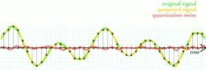
The digitally encrypted word characterized by the amplitude closest to the actual sampled value is used. This is named as quantizing and process entitled as quantization. As an alternative of using the similar sample value of the analog form w(kTs), the nearby allowable value substitutes the sample, where there are M allowed values, each corresponding to one of the code words. Other widespread categories of A-to-D conversions, i.e, Delta-modulation (DM) and the differential pulse code modulation (DPCM), are discussed later.

Important features of Pulse Code Modulation:

Pulse coded modulation has various features. Some of the important features of Pulse Code Modulation are the following:

  • PCM technique is comparatively cheap digital circuitry and could have used extensively for various applications.
  • Pulse Code Modulation signal is resulting from all categories of analog signal (vedio, audiovisual, etc.) combination with data signal (i.e., available from the digital computers or laptop) and communicated over a standard fast-speed digital telecommunication scheme. This multiplexing technique is called TDM and is talk over in a separate section.
  • In a distanced digital telecommunication schemes requiring a repeaters, a clean PCM signal restored at the each repeater’s o/p, where the i/p be made up of PCM pulse mixed with noise. Nevertheless, the noise in the i/p signal might create o/p bit-errors in the PCM technique.
  • The signal-noise ratio of a digital system could have improved in comparison to the analog system. The error probability in the system output could be minimized even further by using proper coding based encryption technique. This compensate the main disadvantage of PCM; a much broader bandwidth range than the analogous analog techniques is requirement.

Sampling, Quantizing and Encoding in PCM:

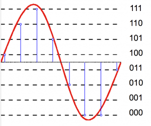
The Pulse Code Modulation signal is generated from the quantized Pulse Amplitude Modulated signal. Quantized values are encoded here.

Generally, a system designer is designated to state the same code word or encryption represented by a specific quantized level for a Gray code. In this resulting Pulse Code Modulation signal, this word or byte for every quantized sample is strobed out the encoder by the next immediate pulse. The Gray code is utilized because, in this, only a one-bit will alter for each step of quantization. Typically, the ‘errors’ in the received PCM signal will cause minimal errors in the received analog signal, provided that the sign bit is not in error.

PCM methods exemplify the quantized analog sample value by the binary codes. As a general rule, it is probable to define the quantized analog samples by digital words using a base other than ‘2’ or, evenly, to transform the binary to other multi-level signal.

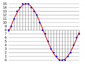
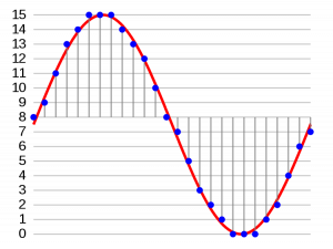
PCM Sampling
This image shows the process of sampling and quantization. Image Credit :anonymous, PcmCC BY-SA 3.0

Operations in the Transmitter:

Sampling

The message signals pass under a process of sampling where they are sampled by the pulse signals. To reform the signal back to its original form, there is a specific condition for sampling rate. The rate must be the multiple of 2 or more of the greatest frequency component present in the signal.

Nyquist’s theorem is one of the important rule in the process of sampling. It deals with the sampling rate and necessary conditions for reconstruction of a signal after being sampled. The theorem is important not only for the Pulse Coded Modulations, but also for each and every modulation techniques and for every aspects of signal theories and signal applications. Mathematically, it says:

Fs >= 2 * Fmax

Here, Fs is the frequency of sampling and Fmax is the value of the greatest frequency component present in the signal.

Antialiasing filters plays a major role here. They omits specific frequency bands which are generally higher than the W.

Three different sampling methods
Image credit : Dr.J.L Mazher Iqbal Slideplayer Presentation

Encoding

Encoding refers to the process of conversion by which datas are symbolised through some specific symbols, or characters. This process brings more security to the communication system. That is why the process is important. For long transmission there is always possibility of unwanted interferences. Encoding saves us from those attacks.

In Pulse Coded modulation technique of transmission, the analog datas are converted to the digital signal. This part of operation is one of the important stage. It can be also stated as the ‘Stage of Digitization’.

The constant communication signal gets converted to distinct values. This distinct procedures in a code is called a code element or symbol. A code element or symbol is given by the discrete events in a code. As we know, the binary codes are given by Zeros and Ones.

Quantization

 “The Quantizing is a procedure of minimizing the extra unnecessary bits and limiting the data.”

State the advantages and disadvantages of PCM:

Advantages  of PCM

  • It transmits signals uniformly.
  • PCM has an efficient SNR.
  • PCM always offers efficient regeneration.

Disadvantages of PCM

  • Attenuation occurs due to noise and cross-talks.
  • PCM needs a larger bandwidth for transmission.
  • Other errors are also observed during transmission.

For more electronics related article click here
Pulse Amplitude Modulation (PAM): 5 Important Explanations

flat top 300x287 1

Subject of Discussion: Pulse Amplitude Modulation (PAM)

  • What is pulse amplitude modulation?
  • Flat top and natural PAM
  • What is PWM and PPM
  • Advantages and disadvantages of PAM
  • Comparison of PAM vs PWM vs PPM

What is Pulse Amplitude Modulation?

Definition of Pulse Amplitude Modulation:

“The modulation technique which is utilized to state the transfiguration of the analog signal to a pulse-type signals in that the amplitude of the pulse signifies the analog info”.

The modulator performs the primary steps while the conversion of analog signal to a Pulse Code Modulated Signal. In a number of application the Pulse Amplitude Modulation signal is used directly and complex conversion such as PCM is not at all required.

Types of Pulse Analog Modulation

The Pulse Analog Modulation can be classified into three categories. They are –

  1. Pulse Amplitude Modulation (PAM)
  2. Pulse width Modulation (PWM)
  3. Pulse Position Modulation

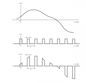
The relation between the pulse and constant amplitude of the message signal is proportional. As explained here, PAM is to a certain extent analogous to natural sampling technique, in which the message signal is multiplied by a periodic square pulses. In regular sampling process, however, the modulated square pulse is acceptable to vary with the message signal, however in pulse-amplitude modulation it is retained as flat signal.


Types of Pulse Amplitude Modulation

Pam can be categorized into two categories. They are – Flattop Pulse Amplitude Modulation and Natural Pulse amplitude modulation.

Flat Top Pulse Amplitude modulation:

The pulses’ amplitudes are dependent on the amplitude of the message signal.

Flat Top Pulse Amplitude modulation

Natural PAM:

Natural Pulse Amplitude modulation

Write down some of the Applications of PAM?

Applications of PAM

There are several applications of Pulse Amplitude modulation such as

  • PAM is used in Ethernet Communication.
  • PAM is used in many micro-controllers to generate some control signals.
  • In Photo-biology system, PAM is also used.

What are the advantages of PAM?

Advantages of Pulse Amplitude modulation

  • Pam is a better straightforward, less complex process for the modulations as well as demodulations.
  • The design of transmitters and receivers of PAM is quite a straightforward job and less complex than other design. 
  • Pulse Amplitude Modulation be able to produce other pulse modulation signals and transport the message signal at that time.

What are the disadvantages of PAM?

Disadvantages of Pulse Amplitude modulation

  • For PAM, bandwidth should be larger for transmission.
  • PAM has a great noise problem.
  • The PAM signal will changes, so that the power requisite for transmission may increase.

What is Pulse Width Modulation?

Definition of Pulse Width Modulation (PWM):

  •  “This is an analog modulating technique in which the duration, width, and time of the pulse carrier will be changed in proportion to the amplitude of the message signals.”
  • The pulses’ widths change in this technique. Though pulse’s magnitude remains the same.
  • In PWM, amplitude limiters are utilized as to create the amplitude of the signal as constant.

This PWM is also recognized as a Pulse Duration Modulation (PDM) and the Pulse Time Modulation (PTM) technique.

PWM
Pulse Width Modulation
An example of PWM in an idealized inductor driven by a voltage source modulated as a series of pulses, resulting in a sine-like current in the inductor.
Image source – ZureksPWM, 3-levelCC BY-SA 3.0
delta PWM
Principle of the delta PWM. Output signal (blue), limits (green).

Image Credit: Delta_PWM.png: Cyril BUTTAY derivative work: Krishnavedala (talk), Delta PWMCC BY-SA 3.0
Sigma Delta PWM

Image Credit :Sigma_delta.png: Cyril BUTTAY derivative work: Krishnavedala (talk), Sigma-delta PWMCC BY-SA 3.0

What is Pulse Position Modulation?

Definition of Pulse Position Modulation (PPM):

In the pulse-amplitude modulation or pulse-width modulation or pulse-length modulation technique, the pulse amplitude is the variable parameter, so it changes. The pulse’s period is one of the important parameter. The modulating signal is changes with the time of incidence of the leading or trailing edges, or both edges of the pulse.

Comparative analysis of PAM, PWM and PPM:

            PAM            PWM             PPM
In PAM amplitude keeps varying.In case of pulse amplitude modulation, the BW is dependent on the width of the following pulse.In PPM, the BW of the pulse is dependent on the rising-time of the pulse.
In PAM, the bandwidth depends on the width of the following pulse.In Pulse Width Modulation, Bandwidth is depended on the rising time of the pulseIn PPM, Bandwidth is depended on the rise time of the pulse
In Pulse amplitude Modulation (PAM) , System or circuit design is complex.In Pulse width modulation (PWM), System or circuit design is less complex.In Pulse position modulation (PPM), System or circuit design is less complex.
  High noise interference  Low noise interference  Low noise interference

For more electronics related article click here
Read more about Amplitude Modulation and Demodulation.

Multiplexing: 7 Important Facts You Should Know

multiplexing 300x198 1

CONTENTS

  • What is Multiplexing ?
  • What are the types of Multiplexing ?
  • Time Division Multiplexing (TDM)
  • Descriptions of TDM
  • Frequency Division Multiplexing (FDM)
  • Descriptions of FDM
  • TDM vs FDM

What is Multiplexing ?

Define Multiplexing:

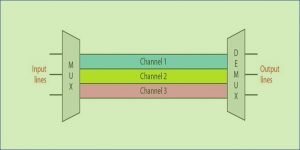
“Multiplexing is a method where many message signs are assembled into a composite signal for the purpose of transmission through a communication channel”.

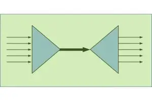
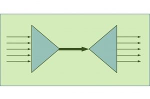
These signals are transmitted through one communication channel. The signals have to be specified so that they do not interfere with one another, and they have to be separated in the receiver end again to recreate the original signal.

Multiplexing
Multiplexing, Image Credit – The AnomeMultiplexing diagramCC BY-SA 3.0

Multiplexing Techniques

It is of two types as follows:

  1. Time Division Multiplexing (TDM)
  2. Frequency Division Multiplexing (FDM)

Time Division Multiplexing:

What is TDM?

Time Division Multiplexing (TDM) is a technique in which a number of signals are made to pass through a common channel at different time slots.

Time Division Multiplexing (TDM)
Image credit: Tony R. Kuphaldt, Telephony multiplexer systemCC BY 1.0

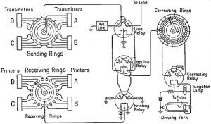
Diagram of TDM:

510px EB1922 Telegraph Simplified Terminal Circuit of Multiplex Printer System
Time Division Multiplexing in Telegraph, Image Credit – William Noble, EB1922 Telegraph – Simplified Terminal Circuit of Multiplex Printer System, marked as public domain, more details on Wikimedia Commons

Here, the TDM technique is employed to the three analog resources that are multiplexed through a PCM system. In practice, a digital switch is utilized for its sampler. This fs = 1/Ts represents the frequency of spinning to its sampler; also fs fits the Nyquist rate for its analog sources with the maximum selective bandwidth. In the certain process where the bandwidth of these is different, the bigger bandwidth resources could be linked to many switch places onto the sampler side to be usually sampled more than the shorter bandwidth input signal.

In the receiver, the sampler needs to be connected with the processed waveform, so the PAM samples corresponding to input one will show up on the channel just only output signal. This is known as ‘frame synchronization’. Lpf has been utilized to rebuild the analogue signals in the PAM samples. ISI resulting in bad channel filtering may induce PCM samples from one communication channel to look on other station, and frame synchronization condition has been maintained. The feedthrough of a one specific communication channel into the other channel is known as cross-talk.

Advantages and Disadvantages of TDM:

Advantages of TDM

  • Usually, TDM is more flexible than FDM.
  • The circuit design of TDM is not complicated.
  • In TDM, less cross-talk has occurred.
  • Channel bandwidth length is longer.

Disadvantages of TDM

  • Frequency Division Multiplexing process has no need of synchronization.
  • Implementation can be complex.

Applications of TDM

  • In ISDN (integrated service digital network), TDM is used.
  • In PSTN (public switched telephone network), TDM is used.
  • In a telephone system, TDM is widely used.
  • TDM is used in telephone wire lines.

Frequency Division Multiplexing:

What is FDM?

Frequency Division Multiplexing is a mechanism of signal transmission in which sharing the available bandwidth of a communication channel occurs among the signals to be transmitted.

In general, FDM schemes are utilized for the analog signal applications.

Diagram of Frequency division Multiplexing:

FDM
Frequency division Multiplexing

FDM is a method of transmitting many messages concurrently through a wideband by modulating the message signals on a few subcarriers and forming a composite baseband signal. This mixed signal is dependent on the quantity of those controlled subcarriers. This mixed signal could then be modulated by AM, DSB, SSB, PM, FM, as the primary types. The type of modulation used in the subcarriers may differ, and also the type used in carrier signal could also differ.

On the other hand, the mixed signal range should consist of inputs signal that should not possess overlapping spectra; otherwise, cross-talk will happen involving the receiver end’s message signals. The mix baseband signal subsequently modulates the transmitter to create the FDM signal sent across the wideband channel.

This FDM collected and demodulated to recreate the combination baseband signal filtered through filters and modulated subcarriers. The sub-carrier has to be demodulated to reproduce the message signals such as m1(t), m2(t) etc.

A speaker with a traditional monaural FM receiver may listen to that the audio sound (composed of the remaining – and the right-channel sound ). By comparison, a speaker with a stereo recipient will get the left-channel sound on the left speaker and the right-channel sound on the ideal speaker. The gap sound is used to govern a 38-kHz DSB-SC sign. Even a 19-kHz pilot tone has been mixed into the mix baseband signal mb(t) to supply a reference sign for coherent subcarrier demodulation in receiver end. As we all know, this program can be used with present FM monaural recipients.

Advantages and Disadvantages of FDM:

Advantages of FDM

· Between the transmitter and receiver, unlike TDM, FDM does not need any synchronization.

· Through FDM, a large number of signals can be transmitted simultaneously.

· Slow, narrowband fading can only affect one single channel.

· Demodulation of FDM is much easier comparatively than TDM.

Disadvantages of FDM

  • This suffers from cross-talk problem.
  • In this type Communication channel must have a large bandwidth.
  • In the technique, its channels get affected due to band fading.
  • In FDM intermodulation distortion takes place.

Applications of FDM

For more electronics related article click here
Phase Modulation And Frequency Modulation: Carson’s Rule

Define Angle or Phase Modulation:

“Angle modulation is a non-linear process and transmission bandwidth is usually much greater than twice the message bandwidth. Because of larger bandwidth, this modulation provides increased signal to noise ratio without increased transmitted power.”

Basically, angle modulation is divided into two categories namely Frequency Modulation & Phase Modulation.

One significant characteristic of  this type is that it can better classify in contrast to noise and interference signal than amplitude modulation. This adjustment in execution is accomplished in the expense of expanded transmission bandwidth; that is, this modulation gives us a method for improved signal to noise ratio.

Besides, this improvement in execution in angle modulation is achieved in the expense of complex circuitry in both the transmitter and receiver section and not possible in Amplitude one.

Mathematical Expression of Angle Modulation:

Let θi(t) signify the angle of a modulated sinusoidal carrier at time t; it is assumed to be a function of the information-bearing signal or message signal. The resultant angle-modulated signal is,

                                    s(t) = Ac cos [θi(t)]

Where Ac is the carrier amplitude, a complete oscillation happens each and every time the angle θi (t) will changed by the value of 2π radians if θi (t) increases with time, then the average freq in hertz, over a trivial intervals of t to t+∆t.

The angle-modulated signal s(t) as a rotating phasor of length Ac and angle θi (t) respectivelySuch a phasor’s angular velocity is dθi (t)/dt, measured in radians/sec. The angle θi (t) is represented for an unmodulated carrier signal,

                            θi (t) = 2πfct + kp m(t)

and the corresponding phasor rotating with a constant angular velocity measured in radians/sec. This constant specify the angle of the unmodulated carrier during that period.

There are various methods in which the angle θi (t) could be changed in a manner w.r.t to the message signal.

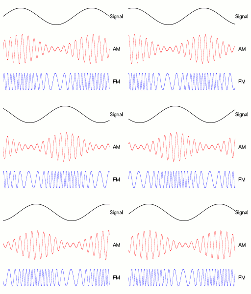
 Diagram of different waveforms of angle modulation:

Amfm3 en de
Diagram of AM, PM and FM waveform made by a single tone: a) the carrier wave   b) the amplitude modulated  c) the frequency modulated signal , Image Credit: BerserkerusAmfm3-en-deCC BY-SA 2.5

 Frequency Modulation:

Frequency Modulation is one form of angle modulation in that instantaneous freq of the carrier is changed  proportionally with the instantaneous amplitude variation of the modulating signal”.

FM is one sort of angle modulation in with  fi (t) is linearly proportional with the message signal m(t) as expressed below,

fi (t) = fc + kf m(t)

The steady value of fc presented to the frequency of the unmodulated carriers signal; the fixed kf termed as modulator’s ‘frequency-sensitivity factor’, measured in hertz per volt on the other hand m(t) is a voltage signal waveform. Integrating w.r.t time and multiply the result by a factor 2π, we can write

2 4

where the 2nd term for the increase or decrease in the instant phase θi(t) due to the message m(t) one. The frequency-modulated signal is consequently,

3 3

Phase Modulation:

Phase Modulation is such type of angle modulation in which the instantaneous angle θi(t)  is linearly proportional with the message ‘ m(t)’ signal as presented by means of,

                                 θi(t) = 2πfct + kp m(t)

The term 2πfct expresses to the un-modulated carrier angle  Øc set to ‘0’ in the phase modulation. The fixed kp value phase sensitivity factor of the modulator, communicated in radians/volt and m(t) is the voltage signal. In the phase modulation, modulated signal s(t) is correspondingly depicted in the time-space by,

                               s(t) = Ac cos [2πfct + kp m(t)]

Show that FM and PM are basically same:

Let the carrier signal is = Ac cos (2πfct)

Let the message signal is = m(t)

So, the expression of F.M. signal is =

4 3

Now if the modulation method is Phase Modulation. then the expression of Phase Modulation signal is

                              = Acos [2πfct + mp . m(t)]

Where, mp is a constant for the Phase Modulation

Also the Phase Modulation signal can be treated as a Frequency Modulation signal where message signal is dm(t)/dt.

So, basically Frequency Modulation and Phase Modulation are basically same.

Pre-Emphasis and De-Emphasis in FM:

A random undesired signal or noise constantly comes with a triangular spectral distribution in a Frequency Modulation technique, together with the impact that noise happens at the maximum frequency of baseband.

This may be offset, to some restricted selection, by raising the frequencies prior to transmitting and decreasing them with a corresponding receiver number. If we decrease the high frequencies from the receiver, then, in addition, it reduces the high-frequency noise.

These practice of increasing and decreasing of these frequencies are called pre-emphasis and de-emphasis, respectively. Most frequently 50 µs time constant is employed.

The total quantity of pre-emphasis which may be implemented is restricted by the simple fact that lots of kinds of modern sound signal comprise higher frequency energy compared to the musical styles that have predominated at the beginning of FM broadcasting.

They cannot be pre-emphasized since it might cause excess deviation. (systems more contemporary compared to FM broadcasting often utilize either programmed-dependent variable pre-emphasis.)

What is Narrow Band FM (NBFM) and Wide Band FM (WBFM ?

The expression for the FM signals is given by

5 2

and hence the instantaneous frequency ωi is given by,

6 1

where, kf = constant of proportionality and kr . em (t) represents the deviation of carrier frequency from the quiescent value ωc. Constant Kf hence controls the frequency deviation. If the Kf is small the frequency deviation is also small and the spectrum of the FM signal is having a narrow band. On the other hand, for higher value of kf, we get wide frequency spectrum corresponding to wideband FM case.

NARROW BAND FM:

The modulation index for narrow band FM is generally near unity and hence for this case, the maximum deviation δ<<fm and the bandwidth is

 B = 2fm.

This bandwidth is same as that occupied by AM signal. The narrowband FM is used wherein intelligible signals for communications are to be transmitted such as in mobile communication used by police, ambulance etc.

WIDE BAND FM:

The modulation index for wideband FM is greater than unity. The bandwidth of a wideband FM system is given by,

                                           B = 2(δ+fm)

For wideband FM δ<<fm and hence B =

Thus, the bandwidth of wideband FM is twice the maximum frequency deviation. The wideband FM is used where the purpose is to transmit high fidelity signals such as in FM broadcasting and TV sound.

For more Modulation And Demodulation related article click here

Modulation And Demodulation:Variants & Advantages

moddddddddd 1024x72 1

Definition of Modulation:

“Modulation is the process of requiring information contained a lower frequency electronic signal onto a higher frequency signal.”

The higher freq signal is named carrier signal and the lower freq signal is termed as the modulating signal.

The upside of sending the higher freq signal is multiple: Firstly if all radio broadcasts broadcast at sound frequencies, they couldn’t be recognized from each other, and just a mix or jumbled signal will be there. Second, it is discovered that specific antenna with a range of 5 miles to 5000 miles is essential for the audio transmissions.

The expression of the modulated carrier wave is,

                                            A sin 2πfct

If, for straightforwardness a particular audio signal is taken as the modulating signal, it can be characterized as,

                                      B sin 2πfat

The modulated signal may be represented by,

                                 (A + Bsin2πfat)(sin 2πfct)

                           V = Vc (1 + B/A sin2πfat) (sin2πfct)

Modulation Factor:

         m = The ratio of “peak value of the modulating signal” with ‘the peak value of the un-modulated signal”

Percent Modulation:

         M = B/A x 100

The modulation percentage may differ somewhere in the range of zero to 100 without distortion. When the per cent modulation is crossing 100 per cent,  noisy frequencies are mixed, and hence distortion is the result.

Types of Modulation:

There are mainly 2 modulation types,

  1. Analog modulation –  It’s a technique of transferring analog baseband signal like audio or TV signal over a higher frequency signal.
  2. Digital modulationthis is a digital technique of encoding digital info.

Again, Analog Modulation has different types; such as

Amplitude Modulation:

“A modulation process in that amplitude of carrier is differed in agreement by means of the instantaneous value of modulating signal is termed as Amplitude Modulation”.

Regarding correspondences, an essential thing for modulation is to encourage the transmission of the data-bearing sign over a radio channel with a recommended passband. In continuous-wave modulation, this is made operational by amplitude or changing the angle of the sinusoidal carrier.

Definitions related to Modulation and Demodulation

Modulation Index of Amplitude Modulation:

Modulation index demonstrates what amount modulated variable of the carrier signal converted around its unmodulated level. In AM , this amount otherwise called modulation depth indicate how much the modulated parameter variable differs around its unique level.Mathematically modulation index is, ma, well-defined by,

moddddddddd

                                                      where, K = proportionality constant;

              Vm = amplitude of modulating signal;

              Vc = amplitude of carrier signal;

Angle Modulation

“Angle modulation is a non-linear process and transmission bandwidth is typically much more than the message band width.

Angle modulation is of two types. They are – Frequency Modulation and Phase Modulation.

A valuable component of angle modulation is that it can give better output in noisy and interference presence than AM technique. This improvement in execution is accomplished to the detriment of expanded transmission data transfer bandwidth; that is good methods for channel bandwidth with improved noise performance. 

Also, in angle modulation, the improvement in execution is possible at the expense of system circuit complexity in both the transmitter and collector. This is not possible in case of amplitude modulation technique.

Angle Modulation can further be divided into:

  1. Frequency Modulation:
  2. Phase Modulation:

Frequency Modulation

Frequency modulation is the form of angle modulation in which instantaneous frequency of the carrier is varied linearly with the instantaneous amplitude change of the modulating signal”.(link wiki)

FM Modulations
Michel Bakni creator QS:P170,Q81411358, FM Modulation – enCC BY-SA 4.0

Frequency Modulation has two important sections:

NARROW BAND FM:

Narrow band Frequency modulation has modulation-index around one. The greatest deviation is δ<<fm. The equation of bandwidth is given by the following equation. a

 B = 2fm.

WIDE BAND FM:

Typically the Wider Band Frequency modulation has modulation index greater than the one. The equation of bandwidth is represented in the following equation.

                                           B = 2(δ+fm)

For wideband FM δ<<fm and hence B =

Phase Modulation:

“Phase Modulation technique is an example for conditioning or tuning the correspondence communication signal for transmission.”

The period of a carrier signal is modulate to follow the changing sign degree of the message signal.

PM is the part of angle modulation where the θi (t) directly proportional to message signal m(t) as appeared by,

                                 θi(t) = 2πfct + kp m(t)

Digital Modulation can further be divided into:

  1. ASK (Amplitude Shift keying)
  2. FSK (Frequency Shift Keying)
  3. PSK (Phase Shift Keying)

What is Demodulation?

Definition of Demodulation:

Demodulation is basically extracting the original information carrying signal from a carrier wave.

Where as a demodulator is an circuitry that is utilized to recover original information or data from the modulated signal.

Some important demodulators (detectors) used for demodulating are:

  • Square law demodulator
  • Envelope detector

There are different demodulation techniques available dependent on the base-band signal parameters, for example,  amplitude, freq or phase angle are transmitted in the carrier signal.  A synchronous detector could be utilized when a signal is modulated with a linear modulation technique. In contrast, a Frequency modulation demodulator or a Phase modulation demodulator can be utilized for a signal attuned with a unintended one.

Comparison between Modulation and Demodulation:

                           MODULATION                      DEMODULATION
This is the process of influencing data information on the carrier. This is the restoration of original information as collected from the carrier. 
In modulation, unique message signal is at all times mixed with carrier signal whose parameters are required modifications In the demodulation technique, the mixture of carrier and message signal is detached from each other, to produce actual signal.
Modulation prerequisites a modulator for the mixing of the two signals. Demodulation prerequisites demodulator to recuperate the original signal. 
Modulation is for transmit data to extensive distance. Demodulation is utilized to regain the original message signal.
Modulation is comparatively simple in between Modulation and Demodulation technique.. Demodulation is comparatively complex in between Modulation and Demodulation technique.
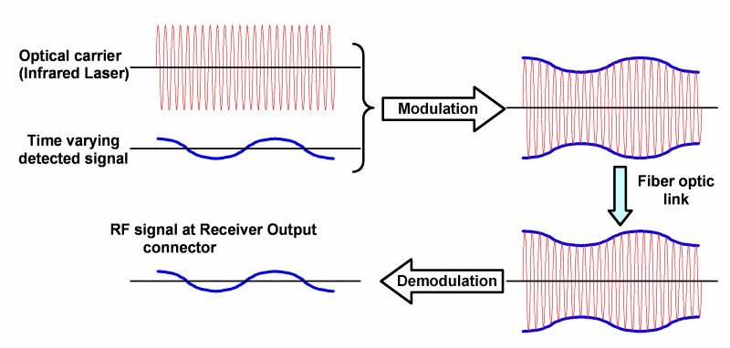
This image has an empty alt attribute; its file name is modulation-and-demodulations.jpg
Modulation And Demodulation
Image Credit : Calzavara S.p.a., Optical modulationCC BY-SA 3.0

For more Modulation And Demodulation related article click here

Amplitude Modulation and Demodulation: 7 Important Facts

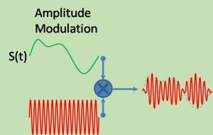
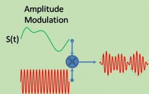
AM Signal 1 300x190 1

CONTENTS

  • What is Amplitude Modulation
  • Virtues, Limitations and Modifications of Amplitude Modulation
  • VSBSC Modulation
  • DSBSC Modulation
  • SSB Modulation
  • DSBSC vs SSBSC
  • Advantages & disadvantages

What is Amplitude Modulation?

Define Amplitude Modulation:

“A modulation procedure where amplitude of carrier is varied with respect to the instantaneous value of modulating signal is called Amplitude Modulation”.

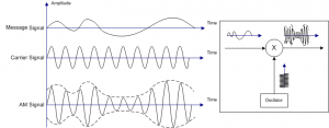
Amplitude Modulation
Amplitude Modulation, Image Credit – Almuhammedi at Arabic WikipediaAmplitude Modulation, marked as public domain, more details on Wikimedia Commons

From the context of communications, a main motivation for the modulation would be to ease transmission of this information-carrying signal over a communication channel or radio station via a prescribed pass-band. On this basis, we might classify continuous-wave modulation to two broad category: amplitude modulation and angle modulation. Both of these modulation differentiate themselves by providing absolutely distinctive spectral features and as a result distinct functional advantages. The classification is completed on the basis of if the amplitude of the sinusoidal carrier wave, or the frequency or phase the angle of the sinusoidal carrier wave, is varied in nature with the information signal.

Illustration of Amplitude Modulation 1
Illustration of AM, Image Credit – Ivan AkiraIllustration of Amplitude ModulationCC BY-SA 3.0

Concepts of Amplitude Modulation:

Consider a carrier signal is characterized by,

                                  C(t) = Ac cos (2πfct)

Here, AC is the carrier signal amplitude and fc is the carrier signal freq. The information or message signal is indicated by term m(t); An amplitude-modulated (AM) wave may thus be described as a function of time as follows:

                                          s(t) = Ac[1+Kam(t)]cos(2πf­ct)

Where Ka is a constant termed as the amplitude sensitivity. Characteristically, the carrier amplitude, message signal are stated in volts, and amplitude sensitivity is represented in volt-1

  1. The amplitude of |Kam(t)| is generally less than unity;

                       |Kam(t)|<1, for all t

  • The carrier freq. ( f­c ) is much higher than the maximum freq. element represented by W of the message signal m(t);

                                         fc >>W

  • For +ve freq., the maximum freq. of the Amplitude modulation wave is equal to (fc + W), and the lowest freq. element is equal to (fc – W). The difference between these two freq. terms as the transmission bandwidth (BT) of the amplitude modulation wave, which is precisely double the message signal bandwidth (W). So

                                     BT = 2W

Modulation Index of Amplitude Modulation:

Modulation index indicates how much modulated variable of the carrier signal fluctuates around its unmodulated level. In Amplitude modulation, this quantity also termed as modulation depth, specifies by exactly how much the modulated variable differs around its original level.

Mathematically modulation index is, ma, defined by,

2 3

     where, K = proportionality constant;

              Vm = amplitude of modulating signal;

              Vc = amplitude of carrier signal;

We know that,

               A = amplitude of modulated signal = Vc(1+masinωmt)

So,          Amax = Vc(1+ma) and Amin = Vc(1-ma)

Finally, modulation index,

3 2

What is VSB-SC Modulation?

Define Vestigial Side Band System Modulation in Amplitude Modulation:

Single sideband modulation works reasonably for an info signal with an energy gap centred around ‘0’ frequency. If more information is to be broadcasted in a given time then corresponding larger B.W. is required, for example: television

  • SSB can play important role in reducing the bandwidth
  • We can analyse the case of video transmission for television system
  • Bandwidth occupied by T.V. video signal minimum 4MHz. So, a transmitted B.W. of 9 MHz at least would be required. So SSB is used for saving the B.W.
  • While using SSB, care must be taken to see at the receiver end. No problem of demodulation arises. So the carrier passed undiminished or as it is.
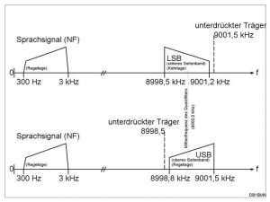
  • As the phase response of the filter at the edges of the flat pass band is loud to have bad effect on video signals received in a T.V. receiver a part of the unwanted i.e., lower sideband also transmitted. The effect of this is to produce a vestigial transmission system also known as AGC. A typical frequency spectrum of this type is shown :
640px Ssb de
SSB, Image Credit – de:User:DB1BMNSsb-de, marked as public domain, more details on Wikimedia Commons
  • 1.25 MHz of the lower side band gets transmitted along with the USB so that the lowest frequencies of the required USB will not be distorted in their phase by the vestigial sideband filter as only 1.25 MHz of the LSB is transmitted; a saving of nearly 3 MHz of V.H.F spectrum is produced with every T.V channel. This makes it promising to allow multiple number of channel is in the same bandwidth.
  • In the above figure, it was observed that the receiver video amplifier frequency response the sound occupies a frequency band near the video amplifier frequency response. The sound occupies a frequency band near the video as it is required with the picture and in practice it is not possible to have separate receiver to receive the sound operating at distant frequency i.e., away from Video Frequency.
  • In television receiver attenuation is intentionally delivered for video frequency from 0 to 1.25MHz. the reason for this is the extra power is transmitted for this part of the information of the video signal as it is transmitted in both sideband this would have produced unnecessary emphasis in the video output of the receiver if the attenuation had been absent.

What is DSB-SC Modulation?

Define Double Side Band Modulation in Amplitude Modulation:

Fundamentally, the double side band suppressed carrier (DSB-SC) modulation comprises of the product of the message signal and the carrier wave as shown in the equation

                              s(t) = c(t)m(t)

                                     = Ac cos (2πfc t) m(t)

Consequently, the device utilized to produce the DSB-SC modulated signal is the denoted to as ‘product modulator’. It is also identified fact that not like AM, DSB-SC modulation is reduced to ‘0’ at whatever time the message signal is not present.

Thus, the apparatus used to create the DSB-SC controlled wave is termed as product modulator. In addition, we understand that unlike any amplitude modulation, DSB-SC modulation is decreased to zero if the message code is switched off.

Mostly, the signal goes into a phase change if the message signal is not zero. The packet of a DSB-SC controlled signal is so dissimilar from the message one, meaning that simple demodulation with the packet detection isn’t a feasible choice for DSB-SC modulation.

DSB-SC features:

  • Only two side-band with suppressed carrier is transmitted
  • With carrier suppressed power saving for m=1 is 66%
  • It requires lesser bandwidth
  • It has balanced modulation

What is SSB-SC Modulation?

Define Single Side Band (SSB-SC) Modulation:

In suppressing the carrier, DSB-SC modulation have a significant limit of Amplitude modulation when it is to this wastage of transmitted electricity. To look after another significant restriction of Amplitude modulation when it comes to station bandwidth, we will have to suppress one of both sidebands from the DSB-SC modulated wave. This adjustment of DSB-SC modulation is exactly what implemented in SSB modulation. In significance, SSB modulation be subject to entirely on the lower-sideband and upper-sideband to transmit the message transfer through communication channels based on which side-band is in fact is communicated.

Single Side Band can be represented mathematically as;

                    sssb (t) = s(t) . cos(2πf0t) – ŝ(t) . sin(2πf0t),

Where, s(t) is the message, ŝ(t) is its Hilbert Transform, and f­0 is the radio carrier frequency.

SSBSC Features:

A SSBSC has the following features:

  • Only one side band is transmitted
  • With one side boundary for m=1 it is 83.3%
  • Its bandwidth is least
  • This is a phase shift method modulator.

Comparison between DSB-SC and SSB-SC:

                  DSB-SC                  SSB-SC
Only two side-band with suppressed carrier is transmitted.   With carrier suppressed power saving for m=1 is 66%   It requires lesser bandwidth     It has balanced modulation    Only one side band is transmitted     With one side boundary for m=1 it is 83.3%   Its bandwidth is least     This is a phase shift method modulator.  

Advantages and disadvantages of Amplitude Modulation:

ADVANTAGES of AM

  • Small antenna size.
  • Long range communication.
  • Using repeater any distance communication is possible.
  • Noise can be eliminated.

DISADVANTAGES of AM

  • Power requirement is high.

For more Electronics related article click here