Friction Factor for Turbulent Flow: What, How to Find

Turbulent flow in the Garbh Uisge geograph.org .uk 2554490 300x225 1

In this article “Friction factor for turbulent flow” and friction factor for turbulent flow related several information will be discuss. The common method is to determine friction factor for turbulent flow is Moody diagram.

The friction factor is a physical parameter which is a dimensionless. The turbulent flow for a particular given type field is constant. The friction factor for turbulent flow only depends on the geometry of the channel and Reynolds number. The flow is called turbulent when Reynolds number is more than 3500.

What is the friction factor for turbulent flow?

Maximum system of the fluid in the nuclear facilities is work with the flow type of turbulent flow. The resistance of this flow obey the equation of Darcy – Weisbach.

The friction of the turbulent flow is measurement of the shear stress which is applied in the wall of a rod or pipe during the flow of turbulent. The flow of turbulent is obeying the equation of Darcy – Weisbach which is directly proportional to square of mean velocity of the flowing fluid in a certain area.

Turbulent flow:-

  1. When the value of Reynolds number is more than 3500 this type of flow called turbulent flow.
  2. Mathematical analysis of the turbulent flow is not too easy.
  3. Velocity of the turbulent flow is too high.
  4. Irregular movement is appearing in fluids which are flow in a motion in turbulent flow.
  5. Average motion is appearing in which side fluid is flowing.
  6. Turbulent flow in general very common type of flow.
  7. The velocity profile of the flow turbulent in a certain area is quickly drops when it comes to the wall of the pipe or rod.
  8. The velocity profile of the flow turbulent in a certain area is clearly flat when it comes to the center section of the rod or pipe.
Turbulent flow in the Garbh Uisge geograph.org .uk 2554490
Image – Turbulent flow in flowing of a river;
Image Credit – Wikimedia Commons

Friction factor for turbulent flow formula:

The Colebrook–White equation is define as f for the Darcy friction factor, the function of for Reynolds number as Re, pipe relative roughness express as, ε / Dh for both smooth pipes and rough pipes.

The friction factor for turbulent flow formula is,

gif.latex?%5Cfrac%7B1%7D%7B%5Csqrt%7Bf%7D%7D%20%3D%20 %202%20log%20%28%5Cfrac%7B%5Cvarepsilon%20%7D%7B3.7%20D h%7D%20+%20%5Cfrac%7B2

or,

gif.latex?%5Cfrac%7B1%7D%7B%5Csqrt%7Bf%7D%7D%20%3D%20 %202%20log%20%28%5Cfrac%7B%5Cvarepsilon%20%7D%7B14.8%20R h%7D%20+%20%5Cfrac%7B2

Where,

Dh (m , ft) = Hydraulic diameter for filling the fluid in circular conduits

Dh = D= Inside diameter of the area from where flow of turbulent is flowing

Rh (m , ft) = Hydraulic radius for filling the fluid in circular conduits

Rh = D/4 = Inside diameter of the area from where flow of turbulent is flowing/4

The equation of Colebrook is solved by numerically for its implicit nature. Now a day Lambert W function is also use to obtain outspoken reformulation the equation of Colebrook.

gif
gif

or,

2%7D

We will get,

px = ax + b

Expanded forms:-

Additional mathematical form of the equation of Colebrook is,

Where,

1.7384…. = 2 log (2 * 3.7) = 2 log (7.4)

18.574 = 2.51 * 3.7 * 2

And,

gif.latex?%5Cfrac%7B1%7D%7B%5Csqrt%7Bf%7D%7D%20%3D%201.1364%20.....%20 %202%20log%20%28%5Cfrac%7BD h%7D%7B%5Cvarepsilon%20%7D%29%20 %202%20log%20%281+%20%5Cfrac%7B9

Or,

gif.latex?%5Cfrac%7B1%7D%7B%5Csqrt%7Bf%7D%7D%20%3D%201.1364%20.....%20 %202%20log%20%28%5Cfrac%7B%5Cvarepsilon%20%7D%7BD h%7D%20+%20%5Cfrac%7B9

Where,

1.1364…. = 1.7384… = – 2 log (2) = 2 log

(7.4) – 2 log (2) = 2 log (3.7)

9.287 = 18.574/2 = 2.51 * 3.7

How to calculate friction factor for turbulent flow?

The process of calculating friction factor for turbulent flow is given below,

  1. At first we need to determine the value of Reynolds number for the turbulent flow using this formula,
  2. ρ x V x D x μ
  3. In the next step relative roughness should be calculated using k/D formula which value to under 0.01
  4. In the final step use the Moody formula for the roughness with the help of Reynolds number,

Friction factor for turbulent flow in pipe:

The range friction factor for turbulent flow in pipe is

For smooth pipe,

0.04 At Re 4000 to 1.01 at Re 3 x 10⁶

For rough pipe,

0.045 At Re 4000 to 0.03 at Re 3 x 10⁶

Friction factor for turbulent flow in smooth pipe:

Friction factor for turbulent flow in smooth pipe can be explained by the help of Blasius correlation. Blasius correlation is the simplest form of determine the Darcy friction factor.

Blasius correlation is only applicable for turbulent flow in smooth pipes it is not applicable for turbulent flow in uneven pipes. The value of 100000 of Reynolds number Blasius correlation is valid. In some cases of turbulent flow in uneven pipes is applied only because of its simplicity.

Mathematical equation of Blasius correlation turbulent flow in uneven pipes is given below,

After that the equation is corrected and express as,

With,

gif

Where,

f is a function for the,

D = Pipe diameter express as meter, feet

R = Curve radius express as meter, feet

H = Helicoidal pitch express as meter, feet

Re = Reynolds number which is dimensionless

Reynolds number valid for,

gif
D%20%3C%20346

0 < H/D < 25.4

Friction factor for turbulent flow in rough pipe:

The Darcy friction factor for turbulent flow in rough pipe means value of Reynolds number is more than 4000 is expressed by Colebrook – White equation.

gif.latex?%5Cfrac%7B1%7D%7B%5Csqrt%7Bf%7D%7D%20%3D%20 %202%20log%20%28%5Cfrac%7B%5Cvarepsilon%20%7D%7B3.7%20D h%7D%20+%20%5Cfrac%7B2

or,

gif.latex?%5Cfrac%7B1%7D%7B%5Csqrt%7Bf%7D%7D%20%3D%20 %202%20log%20%28%5Cfrac%7B%5Cvarepsilon%20%7D%7B14.8%20R h%7D%20+%20%5Cfrac%7B2

Where,

Dh (m , ft) = Hydraulic diameter for filling the fluid in circular conduits

Dh = D = Inside diameter of the area from where flow of turbulent is flowing

Rh (m , ft)= Hydraulic radius for filling the fluid in circular conduits

Rh = D/4 = Inside diameter of the area from where flow of turbulent is flowing/4

The equation of Colebrook is solved by numerically for its implicit nature. Now a day Lambert W function is also use to obtain outspoken reformulation the equation of Colebrook.

gif
gif

or,

2%7D

We will get,

px = ax + b

Expanded forms:-

Additional mathematical form of the equation of Colebrook is,

Where,

1.7384…. = 2 log (2 * 3.7) = 2 log (7.4)

18.574 = 2.51 * 3.7 * 2

And,

gif.latex?%5Cfrac%7B1%7D%7B%5Csqrt%7Bf%7D%7D%20%3D%201.1364%20.....%20 %202%20log%20%28%5Cfrac%7BD h%7D%7B%5Cvarepsilon%20%7D%29%20 %202%20log%20%281+%20%5Cfrac%7B9

Or,

gif.latex?%5Cfrac%7B1%7D%7B%5Csqrt%7Bf%7D%7D%20%3D%201.1364%20.....%20 %202%20log%20%28%5Cfrac%7B%5Cvarepsilon%20%7D%7BD h%7D%20+%20%5Cfrac%7B9

Where,

1.1364…. = 1.7384… = – 2 log (2) = 2 log

(7.4) – 2 log (2) = 2 log (3.7)

9.287 = 18.574/2 = 2.51 * 3.7

Friction factors for turbulent flow in curved pipes:

In order to calculate the pressure drop with in a coil or pipe the friction factor should be calculated at first.

Friction factors for turbulent flow in curved pipes is discuss below,

D = Internal diameter of the coil or pipe

R = Darius of the coil or pipe helix

De = Dean Number

Rec = Transitional Reynolds number

fc = Friction factor of the coil or pipe which smooth

frough = Friction factor for a rough coil or pipe

fsmooth = Friction factor for a smooth coil or pipe

When a single phase flow is appear in a pipe or coil which shaped is curved a secondary flow pattern is introduce in the coil or pipe, in this time friction factor and fluid behaviour start to changes.

As the effect of stabilization of fluid flow the output is comes increases the Reynolds number at that point when flow is enter to the coil or pipe the transition flow form laminar flow to the flow of turbulent.

This condition mathematical form is given below,

gif

To calculate the friction factor in a pipe or coil the Dean number is needed,

gif

After this we easily can determine the friction factor for a smooth coil or pipe.

For,

De < 11.6

fc = 64/Re

For,

11.6 < De < 200

For, De > 2000

For calculation of totally turbulent flows determine the friction factor for a smooth coil or pipe using this equation,

The range is,

gif

Moody diagram friction factor for turbulent flow:

In the flow of turbulent the relation between Reynolds number represent as Re, friction factor represent as fD, and relative roughness represent as ∈/D is complicated.

The expression for Moody diagram friction factor for turbulent flow is,

D%20%7D%7B3.7%7D%20+%20%5Cfrac%7B2
Friction factor for turbulent flow
Image – Darcy Friction factor for Re between 10 and 10E8 for values of relative roughness;
Image Credit – Wikimedia Commons

Frequent Asked Questions:-

Question:- Write about the Darcy friction factor chart.

Solution:- Darcy friction factor chart is combination of four physical parameters such as, pressure loss coefficient, Reynolds number, and relative roughness of the coil or pipe and diameter ratio of the coil or pipe.

Darcy friction factor chart is dimensionless physical factor with the help of Darcy – Weisbach equation can be written as,

gif

Pressure drop can be calculate as,

gif

Or,

gif
772px Equal friction chart for air in metal duct ε 0.05mm.svg
Image – Equal-friction chart for air in metal duct (ε = 0.05 mm);
Image Credit – Wikimedia Commons

The expression for Darcy friction factor for laminar flow is,

fD = 64/Re

In the flow of turbulent the relation between Reynolds number represent as Re, friction factor represent as fD, and relative roughness represent as ∈/D is complicated.

The expression for Darcy friction factor for turbulent flow is,

D%20%7D%7B3.7%7D%20+%20%5Cfrac%7B2

13 Thermal Insulation Examples: Detailed Insights

blue 5457731 960 720 300x169 1

In this article “Thermal insulation examples” will be discuss with its related several facts. Thermal insulation examples are not suitable for transferring the heat from one circumstance to another circumstance.

13+ Thermal Insulation Examples with several facts are listed below,

Thermal insulation examples:-

In our surroundings lots of insulators are present in solid state. The examples solid state insulators are,

Glass:-

  1. The solid insulator example is glass. From the definition of thermal insulation we can get an idea that the heat cannot from one space to another space. The electrons which are present in the glass not able to carry heat just because of the electrons are participating chemical bonds for this reason the electrons are could not get free time to conducting heat and heat cannot flow from circumference to another circumference.
  2. Ordinary glass is appropriate example of solid thermal insulator just one problem with the glass is it is brittle.
  3. Dielectric constant in nature.
  4. Glass has very less temperature coefficient.
Thermal insulation examples
Image – Blue Crystal Cube made with glass;
Image Credit – pixabay

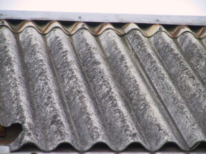
Asbestos:-

  1. The solid insulator example is Asbestos. The electrons which are present in the asbestos not able to carry heat just because of the electrons are participating chemical bonds for this reason the electrons are could not get free time to conducting heat and heat cannot flow from circumference to another circumference.
  2. Not brittle
  3. Resistance to heat
  4. Resistance to wear
  5. Flexible
  6. High strength
800px Wellasbestdach 233 3354 IMG
Image – Asbestos;
Image Credit – Wikimedia Commons

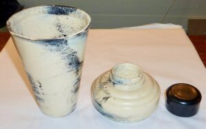
Bakelite:-

  1. Bakelite is heat proof.
  2. Bakelite material is acid proof.
  3. Bakelite is a material which is very strong in mechanically.
  4. Bakelite is a polymer which made with monomers of formaldehyde and phenol.
  5. Another solid insulator example is Bakelite. The electrons which are present in the Bakelite not able to carry heat just because of the electrons are participating chemical bonds for this reason the electrons are could not get free time to conducting heat and heat cannot flow from circumference to another circumference.
1024px Bakelite Cocktail Shaker
Image – Bakelite Cocktail Shaker; Image Credit – Wikimedia Commons

Mica:-

  1. Highly reflective.
  2. Flexible
  3. Another example of thermal insulator is Mica. The electrons which are present in the mica not able to carry heat just because of the electrons are participating chemical bonds for this reason the electrons are could not get free time to conducting heat and heat cannot flow from circumference to another circumference.
  4. Low thermal conductivity.
  5. Mica affected by oil.
  6. Mica is rigid.
  7. In high temperature mechanically the mica became week.
  8. High dielectric strength is about 30 kV/mm.

Rubber:-

  1. Rubber is the insulator of thermal example. The electrons which are present in the rubber not able to carry heat just because of the electrons are participating chemical bonds for this reason the electrons are could not get free time to conducting heat and heat cannot flow from circumference to another circumference.
  2. Rubber has tensile strength.
  3. Tear resistance
  4. Elongation
  5. Abrasion resistance
  6. Specific gravity
  7. Tensile modulus
  8. Hardness

Paper:-

  1. The electrical property of the paper is adequately good.
  2. Paper is made from wood pulp after that manila fibers are beaten and finally rolled into sheets.
  3. Another solid insulator example is Paper. The electrons which are present in the paper not able to carry heat just because of the electrons are participating chemical bonds for this reason the electrons are could not get free time to conducting heat and heat cannot flow from circumference to another circumference.
  4. Papers have dielectric strength near about 4 to 10 kV/mm.
  5. Hygroscopic
  6. The application of paper is wallpaper, filter paper, writing, toilet tissue, security paper and laminated worktops.

Silk or cotton:-

  1. Elasticity
  2. Light weight
  3. Easy to use
  4. Initial cost is low
  5. Available
  6. Silk or cottons have dielectric strength
  7. Thermal insulator another example is Silk or cotton. The electrons which are present in the silk or cottons not able to carry heat just because of the electrons are participating chemical bonds for this reason the electrons are could not get free time to conducting heat and heat cannot flow from circumference to another circumference.
  8. Silk or cottons can be used in various ways such as cooking oils, making of clothes, towels, sheets, currency paper, animal feed biofuels and many more.
Rajshahi silk fabric Sopura Silk Mills Ltd 01
Image – Rajshahi silk fabric,
Image Credit – Wikimedia Commons

Ceramics:-

  1. Ceramics materials are brittle type
  2. Hard
  3. Nonmagnetic
  4. Another solid insulator example is Ceramics. The electrons which are present in the ceramics not able to carry heat just because of the electrons are participating chemical bonds for this reason the electrons are could not get free time to conducting heat and heat cannot flow from circumference to another circumference.
  5. Oxidation resistant
  6. Prone to thermal shock
  7. Ceramics are both thermal insulator and electrical insulator
  8. Ceramics uses in cutting tools, in space industry.
  9. Ceramics works as both thermal insulator and electrical insulator.

Dry air:-

  1. Dry air is thermal insulator. The electrons which are present in the Bakelite not able to carry heat just because of the electrons are participating chemical bonds for this reason the electrons are could not get free time to conducting heat and heat cannot flow from circumference to another circumference.
  2. Dry air not easily affected by heat
  3. Exerts pressure
  4. Can be compressed
  5. Affected by altitude
  6. Economical
  7. Eco friendly
  8. Light weight
  9. Easy to use
  10. Initial cost is low
  11. Available

Wood:-

  1. Wood has good amount of strength.
  2. Wood is another example for thermal insulator. The electrons which are present in the wood not able to carry heat just because of the electrons are participating chemical bonds for this reason the electrons are could not get free time to conducting heat and heat cannot flow from circumference to another circumference.
  3. Wood has both two characteristics such as tension and compression
  4. Rigid
  5. Relatively light weight
  6. Easy to install
  7. Economical
  8. Eco friendly
  9. Any type of size and shape can be given to wood.
  10. Wood can be used in various fields such as packing, weapons, tools, paper, artwork, constructions and many more.

Diamond:-

  1. Diamond is not brittle type
  2. Another example is Diamond of thermal insulator. The electrons which are present in the diamond not able to carry heat just because of the electrons are participating chemical bonds for this reason the electrons are could not get free time to conducting heat and heat cannot flow from circumference to another circumference.
  3. Diamonds have thermal conductivity
  4. Combustibility
  5. Compressive strength
  6. Tear resistance

Plastic:-

  1. Plastic is water resistant
  2. Plastic is shock resistant
  3. Another example is plastic of thermal insulator, the electrons which are present in the plastic not able to carry heat just because of the electrons are participating chemical bonds for this reason the electrons are could not get free time to conducting heat and heat cannot flow from circumference to another circumference.
  4. Light weight
  5. Easy to install
  6. Maintenance cost in very minimal
  7. Easy to give size and shape
  8. Combustibility
  9. Compressive strength
  10. Recyclable
MUOVI Kaimu
Image – Containers made with plastics; Image Credit – Wikimedia Commons

Styrofoam:-

  1. Styrofoam is another example of thermal insulator. Thermal insulator material means from where heat cannot flow one area to another area among them Styrofoam is. The electrons of the Styrofoam could not carry electrons just because of the electrons which are present in the Styrofoam they are engage to make chemical bonds to each other for this reasons the electrons are not free to take part in the conduction of heat, for this reason heat could not flow through Styrofoam material.

Vapor Compression Refrigeration Cycle: What, Diagram, Efficiency, Working, Steps

vapor compression refrigeration cycle 0

In this article the “Vapor compression refrigeration cycle” topic and vapor compression refrigeration cycle related facts are going to summarize to briefly that a clear concept can we get from it effortlessly.

In vapor compression refrigeration cycle a refrigerant which is stays in fluid is used within a system which stays in as closed and proposed to going in four methods such as compression, then cooling with condensation, after that that expansion and lastly heating with evaporation.

What is vapor compression refrigeration cycle?

In the system of air conditioning the vapor compression refrigeration cycle is commonly used. The fluid which is works as medium in the vapor compression refrigeration cycle is states in vapor state.

Vapor compression refrigeration cycle can be explain in this way lowering the inside temperature of a closed system than the normal temperature and helps to reject the excess amount of heat from the area of the closed system and after doing this process finally transfer the excess amount of heat in environment.

Vapor compression refrigeration cycle
Image – A simple stylized diagram of a heat pumps’s Vapor compression refrigeration cycle
1. Condenser; 2. Expansion valve; 3. Evaporator; 4. Compressor ;
Image Credit – Wikipedia

The compression refrigeration cycle of vapor is used in many purposes like, for domestic purposes, commercial purposes, industrial services and automobile sectors.

In vapor compression cycle the refrigerants which are used commonly they are, NH­_3, R – 12, and R- 11. In the vapor compression cycle of a refrigeration system which components are used they are listed below,

  • Refrigerant compressor
  • Liquid compressor
  • Liquid receiver
  • Evaporator valve

Expansion valve These Evaporator valve and Expansion valve both are called as refrigerant control valve.

Vapor compression refrigeration cycle diagram:

The Vapor compression cycle contain liquid refrigerant which act as a medium of the vapor compression refrigeration cycle. The refrigerant changes state of phase during the process for two times.

A simple type of vapor compression refrigeration cycle diagram if we observe then can found main four components.

They are components are,

Compressor:-

The refrigerant when it is vapour state that time it carry lower temperature and lower pressure than the regular one and enters to the compressor of the vapor compression refrigeration cycle from the evaporator of the system. After enter to the evaporator the vapour became carry higher temperature as well as higher pressure. The refrigerant vapor of the system which carries higher temperature and higher pressure is entering to the condenser with the help of discharge valve.

Condenser:-

In the condenser when the refrigerant vapors of the system which carries higher temperature and higher pressure is enter that time the vapor of the refrigerant became condensed and cooled for the coils are present in the pipe inside the air conditioning system.

When the refrigerant is go through the condenser that time latent heat is emitted in the surrounding of the condensing medium which consider as water or air.

Read more about Hydrocyclone Separator

Receiver:-

The liquid refrigerant which is in condensed state of phase is stored in a container from the condenser. The container where liquid refrigerant is stores is known as receiver. After go through the condenser liquid refrigerant is comes to the evaporator by the evaporator valve.

Expansion valve:-

Another name for the expansion valve is throttle valve. The function of expansion valve is to give permission to liquid refrigerant go through with high temperature and high pressure where the liquid refrigerant could reduce its pressure and temperature.

Evaporator:-

In the evaporator of any cooling system contain pipes or coils where the liquid refrigerant has low temperature and low pressure. In evaporator liquid refrigerant is evaporated and transfer into vapor refrigerant where the temperature and pressure is both are stays in low.

In the beginning of the process the liquid refrigerant change its state of phase liquid to vapor and after that the liquid refrigerant change state of phase from vapor state to liquid.

Vapor compression refrigeration cycle T-S and P-V diagram:

For any cooling system the cycle process of vapor compression can be figure out with the help of Pressure – Volume diagram and Temperature –Specific entropy diagram.

Pressure – Volume diagram

512px Refrigeration PV diagram.svg
Image – Pressure – Volume diagram; Image Credit – Wikipedia

Temperature –Specific entropy diagram

RefrigerationTS
Image – Temperature –Specific entropy diagram;
Image Credit – Wikipedia

If we observe the Pressure – Volume diagram and Temperature –Specific entropy diagram then can figure out refrigerant vapor is entr to the compressor in dry saturation situation. After that the saturated and dry refrigerant vapor is enter to the compressor of the refrigeration system at the point 1 where the vapor refrigeration is compress in isentropically process. Now the vapor refrigerant is go from 1 point to 2 point at this particular time pressure is increases from pressure of evaporator to pressure of condenser.

Now at the point 2 saturated refrigerant vapor is enter to the condenser. In condenser heat is emitted at the fixed pressure. For emission of heat normally temperature of the system is decreases and at the same time change of phase is happened. Latent heat is rejected and reaches to liquid refrigerant at saturation temperature at the point of 3.

Then the liquid refrigerant is passes by the expansion valve. In this situation liquid refrigerant decreases its pressure and throttle upbringing the enthalpy constant.

How vapour compression refrigeration system works?

The Vapor compression cycle is a method which is most commonly used in various fields because its cost of charge is very low and the construction of the vapor compression cycle is quite easy to establish.

The cycle process of vapor compression in refrigeration system is working based on reverse Rankine cycle. The Vapor compression cycle process is proceeding in four steps. They are listed below,

Refrigeration
Image – The cycle process of vapor compression in refrigeration system; Image Credit – Wikipedia

In this below section the four steps are discusses,

Compression (Reversible adiabatic compression):

 The refrigerant of vapor compression cycle at low temperature and pressure stretched from evaporator to compressor where the refrigerant is compressed isentropically. The pressure is rises from p1 to p2 and temperature is rises from T1 to T 2.  The total workdone per kg of refrigerant happened during isentropic compression can be express as,

w = h2 – h1

Where,

h1 = Amount of enthalpy of vapor compression cycle in temperature T1, at the step of suction of compressor

h2  = Amount of enthalpy of vapor compression cycle in temperature T2, at the step of discharge of compressor.

Condensation (Constant pressure heat rejection):

The refrigerant of vapor compression cycle is passes through from compressor to condenser at high temperature and pressure. At constant pressure and temperature the refrigerant is completely condensed. The refrigerant changes its state from vapor to liquid.

Throttling (Reversible adiabatic expansion):

At high temperature and high pressure the refrigerant of vapor compression cycle is expanded through the process of throttling. That time the expansion valve is stays in low temperature and pressure. A little amount of liquid refrigerant is evaporating by the help of expansion valve and a huge amount of liquid refrigerant is vaporised by the help of evaporator.

Evaporation (Constant pressure heat addition):

The refrigerant mixture of vapor and liquid is completely evaporated and changed itself into vapor refrigerant. During this evaporation process the refrigerant is absorb latent heat which state is cool. The amount of latent heat absorption by the refrigerant in vapor cycle is known as Refrigerating effect.

Performance of vapour compression cycle in the refrigeration system:

The vapour compression cycle in the refrigeration system is working at evaporator in the law of Steady Flow Energy Equation,

h4 + Qe = h1 + 0

Qe = h1 – h4

The vapour compression cycle in the refrigeration system is working at condenser in the law of Steady Flow Energy Equation,

h2 + Qc = h3 + 0

Qc = h3 – h2

The vapour compression cycle in the refrigeration system is working at expansion valve in the law of Steady Flow Energy Equation,

h3 + Q = h4 + W

We know, value of Q and W is 0

So, we can write,

h3 = h4

Performance of vapour compression cycle in the refrigeration system is,

gif

Vapor compression refrigeration cycle steps:

Vapor absorption cycle process is done by four steps.

Compression process:

In first of the Vapor absorption cycle process compression process is done. In this process vapor stays at very low pressure and temperature.  The vapor is enters to the compressor when it is compressed subsequently and isentropically. After this both temperature and pressure are increases.

Condensation process:

After completing the process in compressor vapor enter to condenser. The vapor is condensed in the high pressure and goes to the receiver tank.

Expansion process:

After completing the process in condenser vapour enter to expansion valve from receiver tank. The throttling process is done in the low pressure and low temperature.

Vaporization process:

After completing the process in expansion valve vapour enter to evaporator. In the evaporator the vapour is extracts heat and circulating fluid in the surrounding environment and in lower pressure vapour is vaporized.

If without throttling expansion is takes place then the level of temperature will be drop in very low temperature and undergoes sensible heat, latent heat to particularly reach to stage of evaporation.

Increasing Vapor compression refrigeration cycle efficiency:

Increasing Vapor compression refrigeration cycle efficiency in a system is listed below,

  1. Optimize setting
  2. Size of the compressors to match loads as nearly as possible
  3. Install VFDs on screw compressor
  4. Install VFDs on motor of the compressor
  5. Use integrated automation system
  6. Use floating head pressure to maintain ideal temperature.

Actual vapor compression refrigeration cycle:

Actual vapor compression cycle refrigeration cycle is not same process as the theoretical vapor compression refrigeration cycle. In the actual vapor compression cycle loss and unavoidable vapor is present.  The refrigerant leaves the evaporator in the state of superheat.

Frequent Asked Questions:-

Question: – Mention the characteristics for good refrigerant.

Solution: – Refrigerant is actually a medium which carry heat during the process of the vapor compression refrigeration cycle. In the refrigeration system heat is absorb from a lower temperature system and after that heat is rejected so system can absorb higher temperature.

The characteristics for good refrigerant is listed below,

  1. Refrigerant should have high critical temperature
  2. Refrigerant should have low boiling point
  3. Non toxic
  4. Non flammable
  5. Non explosive
  6. High latent heat of vaporization
  7. Non corrosiveness for the metals uses in the system of vapor compression refrigeration cycle
  8. Low specific heat of liquidity refrigerant
  9. Low specific heat of vaporized refrigerant
  10. Easy to identified leaks by taking smell or suitable indicator
  11. Easy to liquefy at moderate temperature and pressure.
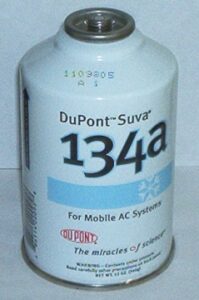
Can of DuPont R 134a refrigerant
Image – Refrigerant; Image Credit – Wikipedia

Question: – Describe the major difference between Carnot cycle and Rankine cycle.

Solution: – The major difference between Carnot cycle and Rankine cycle is discuss below,

Parameter Carnot Cycle Rankine Cycle
Definition Carnot cycle in not a practical cycle it’s a theoretical cycle. The efficiency of the carnot cycle is highest between difference of two temperature Rankine cycle in not a theoretical cycle it’s a practical cycle.
Ideal for Carnot cycle appropriate for heat engine. Rankine cycle is appropriate for vapor compression refrigeration cycle.
Efficiency Efficiency of carnot cycle is higher than the rankine cycle. Efficiency of rankine cycle is lower than the carnot cycle.
Heat rejection In Carnot cycle heat rejection is done when temperature stays at constant. In Rankine cycle heat rejection is done when pressure stays at constant.

9 Thermal Insulator Examples:Facts Explained And Insights

thermal insulator

Thermal insulators reduce heat transfer. Examples include aerogel (R-value up to 10.3 per inch), vacuum insulated panels (R-value 45), fiberglass (R-value 2.2-2.7 per inch), polystyrene (R-value 3.6-5), and mineral wool (R-value 3.0-3.3). Each material’s effectiveness varies with thickness and application.Lets discuss few of thermal insulator in detail

9+ Thermal Insulator Examples are listed below,

Thermal Insulator Examples:-

Water:-

Water is an example of thermal insulator. The electrons which are present in the water they are engage to make chemical bonds for this reasons the electrons are not free to take part in the conduction of heat, for this reason heat could not flow through it. So, water works as a thermal insulator.

Thermal insulator examples
Image – Water;
Image Credit – Wikimedia Commons

Plastic:-

Plastic is a perfect example of thermal insulator. The electrons which are present in the plastic they are engage to make chemical bonds to each other for this reasons the electrons are not free to take part in the conduction of heat, for this reason heat could not flow through plastic. So, plastic is not good heat conductor it is good insulator.

The plastics types which perfect example of thermal insulator are polyester films, Mylar, Melinex.

Plastic Masks 01
Image – Plastic masks;
Image Credit – Wikimedia Commons

Paper:-

Paper is an example of thermal insulator. Dry papers electrons could not carry electrons just because of the electrons which are present in the dry papers they are engage to make chemical bonds to each other for this reasons the electrons are not free to take part in the conduction of heat, for this reason heat could not flow through paper.

600px Making a paper collage
Image – Paper;
Image Credit – Wikimedia Commons

Glass:-

Glassis an also example of thermal insulator. Thermal insulator means from where heat cannot flow one area to another area. The electrons of the glass could not carry electrons just because of the electrons which are present in the glass they are engage to make chemical bonds to each other for this reasons the electrons are not free to take part in the conduction of heat, for this reason heat could not flow through glass material.

glass from below
Image – Glass;
Image Credit – Wikimedia Commons

Styrofoam:-

Styrofoam is another example of thermal insulator. Thermal insulator material means from where heat cannot flow one area to another area among them Styrofoam is. The electrons of the Styrofoam could not carry electrons just because of the electrons which are present in the Styrofoam they are engage to make chemical bonds to each other for this reasons the electrons are not free to take part in the conduction of heat, for this reason heat could not flow through Styrofoam material.

800px Physical weathering styrofoam cup Lake MIchigan
Image – Styrofoam cup;
Image Credit – Wikimedia Commons

Dry air:-

Dry air is an example of thermal insulator. Density of the dry air is a vital factor which is affects a matters insulation capability.  Density is a physical parameter which depends upon the spacing of the intermolecular of the particles in a matter. For because of dry air is a gaseous matter it can spread particle configure resist heat convection to some degree.

Dry air electrons could not carry electrons just because of the electrons which are present in the dry air they are engage to make chemical bonds to each other for this reasons the electrons are not free to take part in the conduction of heat.

Dry cotton:-

Dry cotton is an example of thermal insulator. From the dry cotton heat cannot flow but from wet cotton heat can flow. Means dry cotton works at insulator and wet cotton works as heat conductor.

The electrons of the dry cotton could not carry electrons just because of the electrons which are present in the dry cotton they are engage to make chemical bonds to each other for this reasons the electrons are not free to take part in the conduction of heat in a system, for this reason heat could not flow through dry cotton material.

800px CSIRO ScienceImage 10736 Manually decontaminating cotton before processing at an Indian spinning mill
Image – Dry Cotton;
Image Credit – Wikipedia

Oil:-

Oil is another example of thermal insulator. The electrons of the oil could not carry electrons just because of the electrons which are present in the oil they are engage to make chemical bonds to each other for this reasons the electrons are not free to take part in the conduction of heat, for this reason heat could not flow through oil material.

The viscosity of the oil is also reason for thermal insulation. The relation between the viscosity and thermal conductivity is when the thermal conductivity is increases

b79e5a9480a6d1b0275857634456b23763f5eafa
Image – Oil;
Image Credit – SnappyGoat.com

Rubber:-

Rubber is an example of thermal insulator. The electrons of rubbers are same like another type of thermal insulators. The electrons of the rubber not free to carry electrons just because of the electrons which are present in the rubber they are engage to make chemical bonds to each other for this reasons the electrons are not free to take part in the conduction of heat, for this reason heat could not flow through rubber made materials.

e1c24bc427c81962929186bf2fa3aa65629c6584
Image – Rubber;
Image Credit – SnappyGoat.com

Frequent Asked Questions:-

Question: – Write the major difference points between the thermal conductor and thermal insulator.

Solution: – The major difference points between the thermal conductor and thermal insulator is discuss below,

ParameterThermal conductorThermal insulator
DefinitionThermal conductor can be explain as, the material which is allow to flow the heat from one are to another area.Thermal insulator can be explain as, the material which is not allow to flow the heat from one are to another area.
Examples1.Silver
2.Iron
3.Aluminium
4.Mercury
5.Brass
6.Copper
7.Bronze
8.Gold
9.Graphite  
1.Water
2.Plastic
3.Paper
4.Glass
5.Styrofoam
6.Dry air
7.Dry cotton
8.Diamond
9.Oil
10.Rubber  
Movement of electronsElectron of the materials can flow the heat one area to another without any limits.Electron of the materials cannot flow the heat one area to another.
Electric fieldExistDoesn’t exist
Applications1.Insulation
2.Phase change materials
3.Conductive polymers
4.Textiles
5.Batteries
6.Heat transfer fluids
7.Additive manufacturing 8.Automotive and Electric vehicles
1.Keep home temperature warm in winter season
2. Keep home temperature cool in summer season
3.Keep liquids cool
4. Keep liquids hot

Question: – Give two examples of Insulation Material.

Solution: – The two examples of Insulation Material are,

Glasswool insulation material:-

Fiber glass insulation material is used almost everywhere. Fiber glass insulation material uses in residential and also in many commercial purposes, industrial applications. The fiber glass insulation material has extremely good quality glass fiber and ubiquitous insulation material. In industries many industrialist produce medium to high density fiber glass insulation material which are higher than the R values than the regular ones.

Benefit using of Fiber glass insulation material:-

  1. Eco friendly
  2. High thermal performance
  3. Light weight

Cellulose insulation materials:-

Cellulose insulation material is used in new buildings and old buildings, ceilings of the cathedral and walls for building cavities. Cellulose insulation material is made with recycled products mainly newspapers are used to make it. Near about 82 percentages to 85 percentages recycled products are used to make this process. In new type of construction cellulose insulation material is used as damp sprayed or dry sprayed.

Benefit using of Cellulose insulation material:-

  1. Eco friendly
  2. Economical
  3. Light weight
  4. Cost is not too high
  5. Non combustible
  6. Easy to install
  7. Maintenance is very less

Read more about Is Water An Insulator?

Drag Coefficient of Sphere: What, How, Examples

800px Drag coefficient of a sphere as a function of Reynolds number 300x185 1

In this article “Drag coefficient of sphere” will be discuss and drag coefficient of sphere related detailed facts will be also explain. Drag coefficient of sphere is very important factor for a matter.

Drag coefficient of sphere derive as, the ratio between the surface area of the sphere of the similar volume for the matter of the body comparative to the surface area for the matter of the body. Drag coefficient of sphere is a physical parameter which is deeply depends upon the shape and size of the matter.

What is the drag coefficient of a sphere?

800px Drag coefficient of a sphere as a function of Reynolds number
Image – Drag coefficient of a sphere as a function of Reynolds number; Image Credit – Wikimedia Commons

The drag coefficient of a sphere is depending upon the geometry of the matter and viscosity of the liquid substance through which the matter can flow.

Drag coefficient of sphere derive as, any sphere shaped matter is move in a motion through a liquid substance is facing the physical parameter of drag. The total amount of force is applied in same direction where shear stress force and pressure acted on the plane of the matter.

How to calculate drag coefficient of a sphere?

Drag pressure coefficient for a sphere shaped matter can calculated using this formula,

Where,

cd = Drag pressure coefficient for a sphere shaped matter

Fd = Drag force for a sphere shaped matter expressed in Newton

A = Plan form area for a for a sphere shaped matter expressed in square meter

ρ = Density of a sphere shaped matter express in kilogram per cubic meter

v = Viscosity a sphere shaped matter express in meter per second

Using the eqn (1) putting the values of mass density, flow speed, drag force and area we can get the value of drag coefficient of a sphere.

For sphere matter the area can be calculated as, A = π r2 ……..eqn (2)

The eqn (2) is applicable for the surface area. Because surface area formula is, A = 4 πr2

Drag coefficient of sphere formula:

The formula of the coefficient of pressure drag is given below,

gif
gif

Where,

Fd = Drag force express in Newton

cd = Drag coefficient

ρ = Density of a liquid substance express in kilogram per cubic meter

 v = Flow velocity of a liquid substance express in meter per second

A =Reference area for a particular body shape substance expressed in square meter

The pressure drag for sphere shape matter coefficient is dependent some several facts such as size and shape means geometry of the sphere body and viscosity of the liquid substance through which sphere shape matter can flow.

Drag coefficient of a sphere vs. Reynolds number:

The Drag coefficient of a sphere is decreases with the Reynolds number and drag coefficient becomes almost a constant (CD = 0.4) for a Reynolds number between 103 and 2×10⁵. As the Reynolds number increases (Re > 2×10⁵), the boundary layer becomes thinner in the front of the sphere and begins its transition to turbulent.

Drag coefficient of sphere
Image – Drag coefficient of a sphere vs. Reynolds number;
Image Credit – Wikipedia

When a system is design which is flow in a motion through a liquid substance that time drag is best for measurement for the system or calculate drag by a simulation. Drag coefficient is frequently helpful revert the data back for a particular analytical model.

The only problem is arising during this process that is one model is not appropriate to derive all type of flow of motion in liquid substance in the region of transition and for both regimes.

Instead of particular practice is use to measure and simulated data to calculate models in each and every flow type regime and after that follow where the models are intersect for calculate the region of transition.

Now we are going to discuss the examples and the Cf expression is consider for both pressure drag and skin friction drag.

Laminar Example:-

Drag coefficient of a sphere vs. Reynolds number for laminar flow can be written as,

Drag coefficient of a sphere vs. Reynolds number for laminar flow equation is perfectly goes with a wide range of Reynolds numbers in a closed system of geometries. Drag coefficient of a sphere vs. Reynolds number for laminar flow equation is not appropriate for low drag Reynolds number that could be less than 36 especially for incompressible or very near to incompressible flow.

In the incompressible or very near to incompressible flow we can observe drag coefficient is close to linear function of the velocity.

Turbulent Example:-

Drag coefficient of a sphere vs. Reynolds number for turbulent can be written as,

Drag coefficient of a sphere vs. Reynolds number for turbulent flow equation is perfectly goes with a one simple range of Reynolds numbers in a closed system of geometries.

Drag force coefficient of sphere:

The most studies case of the drag force coefficient is for sphere shaped matter of the body.

When a sphere shaped body in solid state interact with the fluid that time drag force coefficient is produced on the sphere shaped solid matter. Drag force coefficient of sphere matter is not produced by any type of force field.

Frequent Asked Questions:-

Question: –

Write about Skin Friction drag Coefficient.

Solution: –. Skin Friction drag coefficient is physical parameter which is dimensionless skin shear stress. It is mainly dimensionless because of the dynamic pressure is applied on the matter by the free stream.

Skin Friction drag coefficient formula is,

gif

Where,

Cf = Skin friction coefficient

Tw= Skin shear stress which is applied in the surface plane of the body

v = Free stream speed for velocity of the body

ρ = Free stream speed for density of the body

1/2ρ v2 ≡  q = Free stream dynamic pressure for the body of the matter

Relation with the Reynolds number and the Skin Friction drag coefficient is indirectly proportional to each other. Means if Reynolds number is increases then skin Friction drag coefficient decreases and if the Reynolds number is decreases then skin Friction drag coefficient is increases.

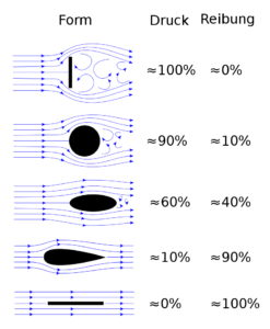
800px Form drag and skin friction ratio.svg
Image – Skin friction drag;
Image Credit – Wikimedia Commons

Laminar flow:-

Where,

Rex = ρ vx/μ Represent the Reynolds number

x = Represent the distance particularly from point of the reference at which the layers of boundary is started.

Transitional flow:-

Where,

gif
%5Crho%20%7D
gif

y = Represent the distance from the wall

u = The speed for the fluid which is flow in a motion and given as y

K1 = Karman Constant

The value of Karman Constant is lower than the 0.41 and Karman Constant is the value for transitional boundary layer and turbulent boundary layer

K2= Van Driest constant

K3= Pressure parameter

gif

p = Pressure

x = The coordinate along a surface where a boundary layers forms

Turbulent flow:-

Question: –

Riva drives her car daily Kolkata to Durgapur. When Riva drives her car that time the speed of the car is about 90 kilometres per hour and that time the drag coefficient is 0.35. The cross sectional area for the car is 6 square meter.

Now determine the amount of drag force.

Solution: – Given data are,

Velocity of the car = 90 kilometres per hour

Drag coefficient of the car = 0.35

Cross sectional area of the car = 6 square meter

Density of the fluid of the car = 1.2 kilogram per cubic meter

We all are know that the velocity of the air is, 1.2 kilogram per cubic meter

Now, applied Drag force formula,

gif

Where,

D = Pressure drag force

Cd= Pressure drag coefficient

ρ = Density

 v = Velocity

 A = Reference area

D = 0.35 * 1.2 * 8100 * 6 /2 * 3600

D = 2.8 Newton

Riva drives her car daily Kolkata to Durgapur. When Riva drives her car that time the speed of the car is about 90 kilometres per hour and that time the drag coefficient is 0.35. The cross sectional area for the car is 6 square meter.

The amount of drag force 2.8 Newton

Question: –

A plane is daily moves Mumbai to Katakana. When the plane moves that time the speed of the plane is about 750 kilometres per hour and that time the drag coefficient is 0.30. The cross sectional area for the car is 115 square meter.

Now determine the amount of drag force for the plane.

Solution: – Given data are,

Velocity of the plane = 750 kilometres per hour

Drag coefficient of the plane = 0.30

Cross sectional area of the plane = 115 square meter

Density of the fluid of the plane = 1.2 kilogram per cubic meter

We all are know that the velocity of the air is, 1.2 kilogram per cubic meter

Now, applied Drag force formula,

D = Cd * ρ * A/2

Where,

D = Pressure drag force

Cd = Pressure drag coefficient

ρ = Density

 v = Velocity

 A = Reference area

D = 3234 Newton

A plane is daily moves Mumbai to Katakana. When the plane moves that time the speed of the plane is about 750 kilometres per hour and that time the drag coefficient is 0.30. The cross sectional area for the car is 115 square meter.

The amount of drag force for the plane is 3234 Newton

Question: –

What is the relationship between drag and Reynolds number?

Solution: – The relationship between drag and Reynolds number is directly proportional to each other. Means if the drag is increases then Reynolds number is also increases and if the drag is deceases then Reynolds number is also decreases.

When Reynolds number is increases that time the viscous forces decreases relative to the internal forces so the point of separation moves in upward direction towards the equator.

7 Types of Insulation Material: Detailed Insights

800px Fs195 cp25 fibreglass pc 300x201 1

In modern generation a wide “Types of insulation material” are very easily available. In these article types of insulation material is prate and also types of insulation material relate facts are derived.

7+ Types of Insulation Material are listed below,

Example of 7+ Types of insulation material and their explanations:-

Glasswool insulation material:-

Glasswool insulation material is used almost everywhere starting from residential glasswool insulation material is used in many commercial purposes and also in industrial applications. The glasswool insulation material has extremely good quality glass fibre and ubiquitous insulation material.

Glasswool insulation material is used in many form of insulation such as loose fill, blanket and also in duct insulation and rigid board. Glasswool insulation material is made with molten glass which is blown or spun into fibres. In most manufacturing industries for made this use 40 percent to 60 percent recycled glass material.

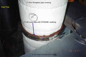
Types of insulation material
Image – Glasswool insulation material;
Image Credit – Wikipedia

Benefit using of Glasswool insulation material:-

  • Light weight
  • Flexible and resilient
  • Non combustible
  • Saves lots of energy
  • Easy to installation and also easy to handle
  • High thermal performance

Earthwool insulation material:-

Earthwool insulation material is generally made with Knauf insulation. Earthwool insulation material is made with a technology which name is ECOSE technology. This type of insulation material most use in residential, industrial and also in commercial.

Benefit using of Earth insulation material:-

  • Non combustible
  • No smell is present in it
  • Long life
  • Acoustic product available
  • High thermal performance
  • Eco friendly
  • Low irritant product material

Rockwool insulation material:-

Rockwool insulation material is an artificial man made insulation material. In rockwool insulation material natural insulation minerals are used such as basalt or diabase. Near about 75 percent recycled materials are used in it. This material can withstand temperature of higher 1000 degree centigrade.

Benefit using of Rookwool insulation material:-

  • Fire resistance
  • High in durable
  • Non combustible
  • Long life
  • High thermal performance
  • High acoustic rating
  • Not affected by water

Polyester insulation material:-

Polyester insulation material is a transparent thermoplastic and it has no colour.  Polyester insulation material is mainly used for making beadboard insulation, loose fill insulation and concrete block insulation carrying small beads of polyester. Thermal resistance of polyester insulation material depend on its density.

In this material near about 50 percentages of recycled products are uses such as bottles of drinking. This type of material is made with heat any type of chemical binder not used in it.

Benefit using of Polyester insulation material:-

  • Non flammable
  • Non toxic
  • Irritant is not appear to touch this polyester insulation material
  • Long life
  • Non allergenic particles

Spray foam insulation material:-

Spray foam insulation material is an expensive material comparative to other insulation materials. For installation and maintenance trained people are used for this reason this insulation material became more expensive.

Benefit using of Spray foam insulation material:-

  • Eco friendly
  • Long life
  • Seal of the spray foam insulation material is airtight
  • Reduce energy bill
  • Help mould growth

Reflective insulation material:-

In the reflective insulation aluminium metal is used which also a reflective type material. Reflective foils are helps to increases the value of the thermal insulation by reflecting the heat to entering into the houses and buildings. The reflective insulation materials uses in for both commercial and residential applications.

Benefit using of Reflective insulation material:-

  • Cost is not too high
  • Non combustible
  • Easy to install
  • Maintenance is very less
  • Non degradable
  • Lightweight and thin
  • Hot climate cannot affect reflective insulation material

Insulation rigid insulation material:-

In the insulation rigid insulation process insulated materials are used such as Kraft paper, aluminium foil and white vinyl sheeting. The materials are used they all are vapour barrio and air barrier. A facing protects is used in insulation rigid insulation process thus insulation can hold together.

Benefit using of Insulated rigid insulation material:-

  • Hot climate cannot affect
  • Vapor and air does not affect on it
  • High thermal performance

Types of insulation material for wall:

The Types of insulation material for wall is listed below,

  1. Nu Wool insulation material
  2. Open cell spray insulation material
  3. Foil faced insulation material
  4. Flash and batt insulation material
  5. Foam board insulation material
  6. Fiberglass insulation material
  7. Wet applied cellulose insulation material

Types of insulation material for transformer:

The Types of insulation material for transformer is listed below,

  1. Pressboard
  2. Insulating tape
  3. Insulating paper
  4. Insulating oil
  5. Wood based laminates

Types of insulation materials of cables:

The types of insulation materials of cables is listed below,

  1. Nylon
  2. Polyurethane
  3. Plastic insulation
  4. Glass
  5. Teflon
  6. Paper

Types of insulation materials in buildings:

The insulation materials which are used in buildings listed below,

Fiber glass insulation materials:-

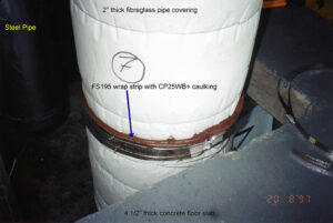
Fiber glass insulation material is used almost everywhere. Fiber glass insulation material uses in residential and also in many commercial purposes, industrial applications. The fiber glass insulation material has extremely good quality glass fibre and ubiquitous insulation material. In industries many industrialist produce medium to high density fiber glass insulation material which are higher than the R values than the regular ones.

800px Fs195 cp25 fibreglass pc
Image – Fiber glass insulation material; Image Credit – Wikipedia

Benefit using of Fiber glass insulation material:-

  • Eco friendly
  • High thermal performance
  • Light weight

Cellulose insulation materials:-

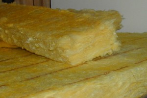
Cellulose insulation material is used in new buildings and old buildings, ceilings of the cathedral and walls for building cavities. Cellulose insulation material is made with recycled products mainly newspapers are used to make it. Near about 82 percentages to 85 percentages recycled products are used to make this process. In new type of construction cellulose insulation material is used as damp sprayed or dry sprayed.

Ecovata
Image – Cellulose insulation material; Image Credit – Wikipedia

Benefit using of Cellulose insulation material:-

  • Eco friendly
  • Economical
  • Light weight
  • Cost is not too high
  • Non combustible
  • Easy to install
  • Maintenance is very less

Mineral wool insulation materials:-

Mineral wool insulation material is made with recycled products mainly industrial products are used to make it. Near about 76 percentages recycled products are used to make this process. Rock wool and slag wool both are manmade products. Rock wool mainly made with natural product such as basalt and slag wool made with blast furnace slag.

Benefit using of Mineral wool insulation material:-

  • Eco friendly
  • Economical
  • Light weight
  • High thermal performance

Insulation facings insulation materials:-

Insulation facings insulation manufacturing process facings are fastened. The facing of the insulation a material protect the surface of the insulation and helps to hold the insulation together. Common material with are used in insulation manufacturing process are aluminium foil, kraft paper and white vinyl sheeting. Vapor barrier and air barrier does not affect on it at all.

Benefit using of Insulation of facings insulation material:-

  • Hot climate cannot affect
  • Vapor and air does not affect on it
  • High thermal performance
  • Eco friendly

Perlite insulation materials:-

The perlite insulation materials uses in very old type buildings. The material of perlite insulation is use as attic insulation. The perlite insulation carry small size and bulky pellets made with heating rock pellets.

Benefit using of Perlite insulation material:-

  • Low cost in install
  • Low maintenance
  • Light weight
  • Easy to install
  • Eco friendly

11+ Thermal Equilibrium Example: Detailed Explanations

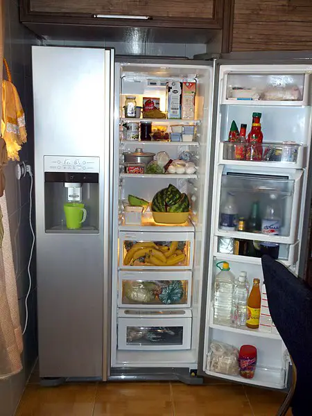
LG refrigerator interior

In this article “Thermal equilibrium example” will be discuss with detailed explanations. Thermal equilibrium example is very important concept to understand the changing of state for a substance.

11+ Thermal Equilibrium Example is encounter in below,

Refrigerator:-

Refrigerator is a device which is appropriate example of thermal expansion. When a food item is stored in the refrigerator that time the item will start to goes down its temperature and the temperature of the refrigerator and the temperature of food item will be same and the process of temperature changing for the food item will be stop.

Refrigerator is a home appliance and commercial appliance. The refrigerator carry a compartment with thermal insulator and also a heat pump through which heat easily can transfer from its midst to its external surrounding. For this process the inside temperature of the refrigerator will be lower than the temperature of the room.

Thermal equilibrium example
Image – Refrigerator;
Image Credit – Wikimedia Commons

Oven:-

Oven is a device which is also an appropriate example of thermal expansion. When a food item is placed in an oven and heat is applied on it that time the item will start to goes up its temperature. When the temperature of the oven and the temperature of food item will be same that time the process of temperature changing between the oven and the food item will be stop.

An oven is use for cooking purpose and also heats the food item to a wished temperature.

Grilled chicken in electric oven Rostov on Don Russia
Image – Grilled chicken in a oven;
Image Credit – Wikimedia Commons

Types of oven:

Types of oven is listed below,

  1. Electric oven
  2. Gas oven
  3. Earth oven
  4. Masonry oven
  5. Toaster oven
  6. Ceramic oven
  7. Wall oven
  8. Steam oven
  9. Microwave oven

Melting of a ice cube:-

Another example of thermal expansion is melting of an ice cube. When an ice cube placed on a normal temperature its try to reaching at the room temperature and melting point will be increases at this particular time ice cube start to changing its state from solid to liquid.

800px Ice cube Air entrapment
Image – Melting of a ice cube;
Image Credit – Wikimedia Commons

Freezing of water:-

Another example of thermal expansion is freezing of water. When water is placed on a lower temperature its try to reaching at the lower temperature from the normal temperature at this particular time water starts to change its state from liquid to solid.

Drying of wet hair:-

Drying of wet hair is another regular example of thermal expansion. When we dry our wet hair in normal room temperature that time our wet hair reach at the room temperature and hair will be dry.

Drying of wet clothes:-

Drying of wet clothes is another regular example of thermal expansion. When we dry our wet clothes in normal room temperature that time our wet clothes reach at the room temperature and cloth will be dry.

Cooling of a cup of tea:-

Cooling of a cup of tea is another regular example of thermal expansion. When a cup of tea is placed on a normal room temperature that time a cup of tea try to reaching at the room temperature and boiling point will be decreases. A cup of tea starts to change its temperature and became cool.

800px Red Tea
Image – Cooling of a cup of tea;
Image Credit – Wikimedia Commons

Melting of ice-cream:-

Another example of thermal expansion is melting of ice cream. When ice cream is placed on a normal room temperature that time its try to reaching at the room temperature and melting point will be increases and freezing point will be decreases. The ice cream starts to change its state from solid to liquid.

Melting ice cream
Image – Melting of ice cream;
Image Credit – Wikimedia Commons

Freezing of ice- cream:-

Another example of thermal expansion is freezing of ice cream. When ice cream is placed on a refrigerator that time ice cream try to reaching at the refrigerant temperature and melting point will be decreases and freezing point will be increases. For this particular reason the ice cream starts to change its state from liquid to solid.

Cooling of a hot rod:-

Cooling of a hot rod is another example of thermal expansion. When a rod has higher temperature after doing any operation it became hotter. When a hotter rod is placed in a normal room temperature that time the rod try to reach at the room temperature. The rod starts to decreases its temperature and became cool.

Making of tea:-

When we make tea that time with hot water milk is added at that time the temperature of milk is low and the temperature of water is cold but when hot water and cold milk is added to each the mixture comes in a normal temperature. So, making of tea is also another example of thermal expansion.

Frequent asked questions:-

Question: –

Write the formula for thermal equilibrium.

Solution: – When two different matters stay in same temperature that’s mean the two different matters maintain thermal equilibrium.

The formula for thermal equilibrium is,

gif

Where,

Q = Total energy of the specific matter of the body which is expressed in Joule

m = Mass of the specific matter of the body which is expressed in grams

Ce = Specific heat of the specific matter of the body which is expressed in joule per Kelvin per kilogram

Δ t = (Final temperature – Starting temperature) of the specific matter of the body which is expressed in Kelvin

Question: –

In a house a bowl is present which is decorated with beautiful stones. The bowl is made with aluminium. The weight of the bowl is 15 gram and temperature is about 39 degree centigrade. Now in the aluminium bowl water is placed. At this condition the temperature of the water will be 20 degree centigrade and weight of the water is about 32 gram.

Find the exact temperature where the temperature of the aluminium and the temperature of the water will be same.

Solution: –

We know that,

gif

Where,

Q = Total energy of the specific matter of the body

m = Mass of the specific matter of the body

Ce = Specific heat of the specific matter of the body

Δt= (Final temperature – Starting temperature) of the specific matter of the body

For aluminium,

Given data are,

mA =  15 gram

CeA = 0.215 calorie per gram degree centigrade

Δ tA = (Tf – TiA) degree centigrade = (Tf – 39) degree centigrade

For water,

QW = mW * CeW *ΔtW………….. eqn (1)

Given data are,

mW = 32 gram

CeW = 1 calorie per gram degree centigrade

ΔtW = (Tf – TiW) degree centigrade = (Tf – 20) degree centigrade

Now, from………….. eqn (1) and ………….. eqn (2) we can write,

gif

Putting the value from eqn (1) and eqn (2),

(Put the value for CeW = 1 calorie per gram degree centigrade)

gif.latex?3.225%20T f%20 %20125

Tf= 21.7 degree centigrade

In a house a bowl is present which is decorated with beautiful stones. The bowl is made with aluminium. The weight of the bowl is 15 gram and temperature is about 39 degree centigrade. Now in the aluminium bowl water is placed. At this condition the temperature of the water will be 20 degree centigrade and weight of the water is about 32 gram

The exact temperature where the temperature of the aluminium and the temperature of the water will be same is 21.7 degree centigrade

Question: –

Explain types of thermodynamic equilibrium.

Solution: – A system is called thermodynamic equilibrium when mechanical equilibrium, thermal equilibrium and chemical equilibrium are same.

Thermodynamic equilibrium three types, they are,

Mechanical equilibrium:-

A system is called mechanical equilibrium when pressure will be no changed in any condition and also no changes in acting of unbalanced force.

Thermal equilibrium:-

A system is called thermal equilibrium when temperature will be no changed in any condition inside the system of the matter.

Chemical equilibrium:-

A system is called chemical equilibrium when chemical reaction no present inside the system and also any type of composition changes is not present of the matter.

9 Thermal Expansion example: Detailed Explanations

Termometros mercurio e infravervelho thermometers 300x225 1

In this article “Thermal expansion example” with detailed explanations will be discuss. Thermal expansion example is use for a substance when it is expands due to high temperature or low temperature.

9+ Thermal Expansion Example is listed below,

Thermometers:-

Thermometer is the example of thermal expansion. Thermometer helps us to measure the amount of temperature or temperature gradient of a system. The thermometer used in many purpose such as science research, manufacturing field or practice of medicine, in automotive sector and many more. Thermometer is a tube which is made of glass material when thermometer is placed in a hot substance the inside liquid takes temperature and increases its volume. In the thermometer body equally divided the measurement scale. When the inside liquid rises up easily we can understand the temperature of the substance.

Thermal expansion example
Image – Thermometer;
Image Credit – Wikimedia Commons

Removing tight lids:-

Sometime a lid of a jar too tight for this difficulty can face for open the lid. We all are know that when expansion is produce in a substance that time the substance is increases its volume area and length. So, facing difficulty opening of a lid if heat up then it’s expand its area and easy to open.

d40167c0130225a42f2101b4ae406b4952425bcc
Image – Removing right lids of a jar;
Image Credit – snappygoat.com

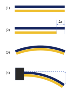
Bimetallic strip:-

Bimetallic strip is a device which is convert temperature into mechanical displacement. Bimetallic strip contain two different type of metal and work on the thermal expansion principle. In the bimetallic strip two metals are expand in different temperature difference.

Bimetallic strip
Image – Bimetallic strips;
Image Credit – Wikimedia Commons

Types:

Bimetallic strips classified in two sections,

Spiral strip type:

Spiral strip type bimetallic strips is contains a structure of spiral like in it a pointer is added thus the pointer can measure the temperature. When the structure of the spring shaped is heated the metals shown their property of thermal expansion and the structure of the spring shaped is deform when temperature is fall. In this period the scale is recorded the amount of temperature. Normally by the help of spiral strip type bimetallic strips we can record the temperature of ambient.

Helical type:

Helical type bimetallic strips is contains a structure of helical like in it a pointer is added thus the pointer can measure the temperature. When the structure of the helical shaped is heated the metals shown their property of thermal expansion and the contracts on cooling. In this period the scale is recorded the amount of temperature. Normally by the help of helical strip type bimetallic strips we can record the temperature of industrial applications.

Advantages of Bimetallic strips:

  • Less cost
  • Robust
  • Simple in use
  • External power not needed
  • Give accuracy in between ± 2 to 5

Disadvantages of Bimetallic strips:

  • Low temperature does not work properly.
  • Measure up to 4000 centigrade

Application:

  • Bimetallic strip use in a fire detector or fire alarm
  • Bimetallic strip use in mechanical clocks for minimize the errors during the changes of temperature.
  • Heaters
  • Iron box
  • Heat engine
  • Thermistor
  • Fans

Riveting:-

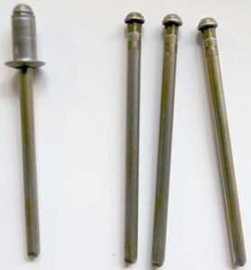
Riveting is work on the basic of thermal expansion. Riveting is a fixed mechanical fastener. Rivets made with aluminium or steel and used to joining the metal pieces.  River joints contain gun, rivet pin and operation with rivet is known as riveting.

558px Blind rivet notches
Image – Rivet;
Image Credit – Wikimedia Commons

Types:

Types of rivet joints are,

  1. Button head rivet
  2. Join our Newsletter rivet
  3. Belt rivet
  4. Hollow rivet
  5. Boiler construction rivet Explosive rivet

Thermostats:-

Thermostat is work on the basic of thermal expansion. Thermostat is a machine by which we can detect the amount of temperature changes. The thermostat uses in valves, switches, relays and many more.

Thermostat is a device which is works on two purposes one is for measurement and another one is for controlling function.

832e978152911fe543c3b66e0319bd853f8907fb
Image – Thermostat;
Image Credit – snappygoat.com

Cracks appearing in the roads:-

Cracks appearing in the roads it are another example of thermal expansion. Cracks in the road mainly happened in the hot afternoon when the temperature is rises too up. In the surrounding the temperature is rise up above the 90 degree and wrap and buckle is appearing.

Hampden Lane cracking. Update 27 April 2010
Image – Cracks appearing in the rod; Image Credit – Wikimedia Commons

Expansion joints:-

An expansion joint is an example of bellows type device. Expansion joints are mainly used for absorbing thermal expansion. In this way the expansion joints are make thus it could grip and holds the parts together when safely taking temperature induced expansion, vibration and also construction of a building material.

Expansion joints are used in railway tracks, sidewalks, buildings, ships, piping system, bridges.

Track Rail Expansion Joint
Image – Expansion joints,
Image Credit – Wikimedia Commons

Metal frame windows need rubber:-

Now in builds or other construction windows are made of metal. In these windows thermal expansion is happened for this particular reason rubber is use outside the frame of the window. Rubber is not good for heat conductor for this reason thermal expansion can be prevents and the frame will be stay at its correct position without any damage.

Tyre of the vehicle gets warm:-

When a vehicle is run for a long distance that time the tyre of the vehicles getting warm and thermal expansion is appear. Heat plays a vital role for getting warm of the vehicle tyres. When heat is increases the inside pressure is also increases for this reason the temperature is also goes up.

Frequent asked questions:-

Question: – Explain the coefficient of thermal expansion for matter.

Solution: – Thermal expansion coefficient is actually a physical condition of substance to change its area, shape, density and volume under changing of temperature. Thermal expansion is not including the phase transitions. The S.I unit of the thermal expansion is per Kelvin.

The equation for thermal expansion coefficient is,

gif

Where,

∝ = Coefficient of thermal expansion for gaseous matter

V = Volume for gaseous matter

T = Temperature for gaseous matter

P = Pressure for gaseous matter

For particularly 1 mole ideal gaseous substance PV = RT,

Where,

∝ = R/PV = 1/T

Types of thermal expansion coefficient:

The thermal expansion coefficient can be divided in three sections,

  • Linear expansion coefficient
  • Area expansion coefficient
  • Volume expansion coefficient

Linear expansion coefficient:-

Linear expansion coefficient can be explained as, changing of length due to temperature.

Linear expansion coefficient can be written as,

gif
gif

Where,

ΔL= Changing in length

L0= Original length

∝ = Length expansion coefficient

L = Expanded length

Δ T = Temperature difference

Area expansion coefficient:-

Area expansion coefficient can be explained as, changing of area due to temperature.

Area expansion coefficient can be written as,

gif
gif

Where,

ΔA= Changing in area

A0= Original area

∝= Area expansion coefficient

A = Expanded area

Δ T= Temperature difference

Volume expansion coefficient:-

Volume expansion coefficient can be explained as, changing of volume due to temperature.

Volume expansion coefficient can be written as,

gif
gif

Where,

Δ V = Changing in volume

V0 = Original volume

∝ = Volume expansion coefficient

V = Expanded volume

ΔT= Temperature difference

Question: –

Rup daily uses a rod or his gardening purpose, one day he forgets to bring the rod at his own house. The length of the rod is 10 meter at the temperature of 39 degree centigrade. After forget the rod the length of the rod became 15 meter and that time the temperature is 35 degree centigrade.

Now determine the thermal expansion coefficient for the rod.

Solution: – Given data are,

Changing in length ΔL = (15 – 10) meter = 5 meter

Original length L0 = 10 meter

 Length expansion coefficient ∝= ?

Expanded length L = 15 meter

Temperature difference Δ T = (39 – 35) degree centigrade = 4 degree centigrade

Absolute temperature = T = (273 + 4) K = 278 K

gif
gif
gif
gif

Rup daily uses a rod or his gardening purpose, one day he forgets to bring the rod at his own house. The length of the rod is 10 meter at the temperature of 39 degree centigrade. After forget the rod the length of the rod became 15 meter and that time the temperature is 35 degree centigrade.

The thermal expansion coefficient for the rod is 17 x 10 -4 K -1

7 Real Gas Examples: Under Which Circumstance

371px Soda fountain in China 01 186x300 1

In this article “Real gas examples” and real gas examples related which circumstances will be summarized. Real gas examples are does not follow the law of gases. Real gas examples works in low temperature.

8+ Ideal Gas Examples are listed below,

Soda fountains (Carbon dioxide):-

The soda fountains is a machine device by which we can get carbonated soft drinks, this types of drinks called fountain drinks. The soda fountains devices are now available in everywhere almost from start to restaurants it easily available in local markets. In the soda fountains machines syrup concentrate or flavoured syrup is mix up with purified and chilled water, carbon dioxide.

With taking the help of soda gun the drinks can easily can out from the device.  Now bag in box soft drinks are kept in the soda fountains device. The carbon dioxide one of the most soluble gas substance among the all toxic gases thus carbon dioxide is the appropriate gas for preserve the drinks.

Real gas examples
Image – Soda fountains;
Image Credit – Wikimedia Commons

Cable TV and WiFi (Helium):-

In cable TV and WiFi connection real gas is use. In telecommunications, cable internet or cable internet access helium gas is use. Now a day uses of internet by help of cable lines gives lots of development and advancement of our busy schedule.

Wireless Screencasting
Image – Cable TV and WiFi;
Image Credit – Wikimedia Commons

Benefit of Cable TV and WiFi:

  • Reliable
  • Admirable service

Light bulbs (Argon):-

Inside the light bulbs argon gas is used. The light bulb mainly depends on the working principle of incandescence. The meaning the incandescence is the light bulbs make light when heat is produced.

When in a thin metal filament of light bulb electric current is flows that time the filament getting heat and after heated it start to glow and in this way light is produce. In the light bulb filaments are made of tungsten because this metal have higher melting point compare to other metal.

Ultraviolet light bulb 2
Image – Light bulbs;
Image Credit – Wikimedia Commons

Bakery products (Carbon dioxide):-

In bakery products carbon dioxide is used.  In bakery products such as pies, rolls, breads, muffins and pastries sodium bicarbonate is uses. When the sodium bicarbonate mixes up with the products of bakery that time carbon dioxide is produce.

800px Chinese bakery eastsection
Image – Bakery products;
Image Credit – Wikimedia Commons

Hot air balloon (Hydrogen and Helium):-

Hot air balloon is lighter than the air craft. The hot air balloons have a big size balloon which is named envelope which has heated air. Inside the hot air balloons hydrogen and helium gas are present. A basket is present in it.

800px Colorado Springs Hot Air Balloon Competition
Image – Hot Air Balloons;
Image Credit – Wikimedia Commons

Opening of a soda bottle (Carbon dioxide):-

In a soda bottle compressed carbon dioxide is uses. The main reason behind using the carbon dioxide inside the bottle is this is the most non toxic gas. The fizz that bubbles up when we crack open a can of soda is carbon dioxide gas CO2. The industrial who make the soft drinks add this tingling froth by forcing carbon dioxide and water into your soda at high pressures—up to 1,200 pounds per square inch.

Fire extinguisher (Carbon dioxide):-

A fire extinguisher which is a device works as a safety device. Inside the fire extinguisher carbon dioxide is placed. It is used to control small size fire thus a big accident can be prevented.

800px Fire extinguishers in a hotel in Coxs Bazar
Image – Fire Extinguisher;
Image Credit – Wikimedia Commons

In general two types of fire extinguisher are available. They are,

  • Stored pressure fire extinguisher
  • Cartridge operated fire extinguisher

Paintball (Nitrogen and carbon dioxide):-

The paintball is a comparative and very fun game. The purpose of the game is to hit a target object with the help of paintball. The gelatine shells are used to make paintballs. Inside the paintball carbon dioxide and nitrogen is placed. Inside the paintball carbon dioxide and nitrogen took place as liquid but when the trigger is pulled that time carbon dioxide and nitrogen under high pressure change its state and became gas.

NAdo JTF3
Image – Paintball;
Image Credit – Wikipedia

Frequent asked questions:-

Question: – What are the properties for the real gas.

Solution: – Real gas isa gaseous matter which are work in higher pressure and lower temperature. In our surroundings real gas are present. Real gases not follow gas law at any particular temperature or pressure.

The properties for the real gas is given below,

  1. When the real gas is comes across the porous plug that time the real gas passes high pressure to the comparative low pressure, for this particular reason temperature is changes.
  2. Real gas substance can be liquidities. The reason behind of it the molecules of the real gas have a physical property that is intermolecular attraction by which molecules can coalesce.
  3. The thermal expansion coefficient is depending upon the character of the real gas molecules.
  4. The compressibility coefficient is depending upon the character of the real gas molecules.
  5. Intermolecular attraction is present in the real gaseous substance. When the real gaseous substance is expanding the particles of the real gaseous substance have more kinetic energy to defeated intermolecular attraction and the temperature is changed.
  6. When the temperature of the real gaseous substance is under the critical temperature that time the molecules of real gaseous substance can liquefied under particular temperature and pressure.

Question: – Explain the coefficient of thermal expansion for gas.

Solution: – Thermal expansion actually a physical condition of substance to change its area, shape, density and volume under changing of temperature. Thermal expansion is not including the phase transitions. The S.I unit of the thermal expansion is per Kelvin.

The equation for thermal expansion coefficient is,

gif

Where,

α = Coefficient of thermal expansion for gaseous matter

V = Volume for gaseous matter

T = Temperature for gaseous matter

P = Pressure for gaseous matter

For particularly 1 mole ideal gaseous substance PV = RT,

Where,

α = RP/V = 1/T

1280px Carnot heat engine 2.svg
Image – Thermal expansion;
Image Credit – Wikipedia

Types of thermal expansion:

The thermal expansion can be divided in three sections,

  • Linear expansion
  • Area expansion
  • Volume expansion

Linear expansion:-

Linear expansion can be explained as, changing of length due to temperature.

Linear expansion can be written as,

gif

Where,

ΔL = Changing in length

L0 = Original length

α= Length expansion coefficient

L = Expanded length

ΔT= Temperature difference

Area expansion:-

Area expansion can be explained as, changing of area due to temperature.

Area expansion can be written as,

gif

Where,

ΔA = Changing in area

A0 = Original area

α = Area expansion coefficient

A = Expanded area

ΔT= Temperature difference

Volume expansion:-

Volume expansion can be explained as, changing of volume due to temperature.

Volume expansion can be written as,

gif

Where,

ΔV = Changing in volume

V0 = Original volume

α = Volume expansion coefficient

V = Expanded volume

 Δ T= Temperature difference

Question: – Explain the coefficient of compressibility for gas.

Solution: – The coefficient of compressibility for gaseous matter is decreasing the amount of volume in per unit volume created by per unit change in pressure.

Read more about Thermal diffusivity : Its’s all important Facts and FAQs

Mathematically coefficient of compressibility written as,

gif

Where,

β = Coefficient of compressibility for gaseous matter

V = Volume for gaseous matter

P = Pressure for gaseous matter

T = Temperature for gaseous matter

Coefficient of compressibility (β) for ideal gases,

gif

Therefore, β should be a function of pressure only and the same for all gases. But experimentally the coefficient of compressibility has been found to be individual property

Question: – Explain the compressibility factor equation for gas.

Solution: – With the help of compressibility factor equation for gas we can understand reach of deviation of real gaseous substance from ideal gaseous substance character.

The compressibility factor equation for gas is,

Z = PV/RT

Where,

Z = Compressibility factor constant for gaseous substance

P = Pressure for gaseous substance

V = Volume for gaseous substance

R = Gas constant for gaseous substance

T = Temperature for gaseous substance

Read more about Pressure vessel design : It’s important facts and 5 parameters

Now, when the value of Compressibility factor constant for gaseous substance

Is equal to 1 (Z = 1) that time no deviation is present from the ideal gaseous substance behaviour.

Now, when the value of Compressibility factor constant for gaseous substance

Is not equal to 1 Z ≠ 1 that time the value of the unit for Z is measure for reach of non ideality.

When the value of Compressibility factor constant for gaseous substance

Is greater than 1 (Z < 1) that time the ideal gaseous substance will be more compressible.

When the value of Compressibility factor constant for gaseous substance

Is less than 1 (Z  > 1) that time the ideal gaseous substance will be not more compressible.

Read more about Specific Enthalpy : Its important properties & amp; 8 FAQ’s

Question: – The difference between real gas and ideal gas describe.

The major points are derive about the difference between real gas and ideal gas,

ParameterIdeal gasReal gas
DefinitionThe gas which are follow the law of gas at particular condition of constant pressure and temperatureThe gas which are not follow the law of gas at particular condition of constant pressure and temperature
FormulaThe formula which ideal gas is follow,
PV = nRT
Where,
P = Pressure
V = Volume
n = Amount of substance
R = Ideal gas constant
T = Temperature
The formula which real gas is follow,
V%5E2%29%28V%20 %20nb%29%7D%20%3D%20nRT
Where,
P = Pressure
a = Parameter which need to determine empirically for individual gas
V = Volume
b = Parameter which need to determine empirically for individual gas
n = Amount of substance
R = Ideal gas constant
T = Temperature  
AvailabilityNot existExist

3 Ideal Gas Examples: Under Which Circumstance:

Boyles Law animated

In this article “Ideal gas examples” and ideal gas examples related facts will be discuss. Ideal gas examples are based on law of ideal gas. But in practical life ideal gas is not present in the universe.

3+ Ideal Gas Examples are listed below,

Example 1:-

Calculate the amount of density for the Nitrogen gas at the pressure of 256 Torr and 25 degree centigrade temperature.

Solution: – Given data are,

P = 256 Torr = 256 Torr x 1 atm/760 Torr = 0.3368 atm

V =?

T = (25 + 273) K = 298 K

n =?

Now we apply the formula for ideal gas,

PV = nRT   ………. eqn (1)

So, we also can write the density is,

ρ = m/v ………. eqn (2)

Where,

ρ = Density of the ideal gas

m = Mass of the ideal gas

v = Volume of the ideal gas

Now, m = M x n ………. eqn (3)

Where,

m = Mass

M = Molar mass

n = Moles

From eqn (2) and eqn (3) we get,

ρ = m/v …… (4)

Arranging the eqn (2) and eqn (3) we get,

ρ = M x n/V ……eqn(5)

ρ/M = n/V……eqn(6)

Now applying the equation of ideal gas,

PV = nRT

n/V =ρ /M ……eqn(7)

n/V = P/RT ……eqn(8)

From eqn (6) and eqn (8) we get,

ρ/M} = P/RT ……eqn(9)

Isolate density,

ρ = PM/RT……eqn(10)

ρ = (0.3368 atm)(2 x 14.01gram/mol)/(0.08206 L*atm*mol-1*K-1 )(298 K)

ρ = 0.3859 gram / mol

The amount of density for the Nitrogen gas at the pressure of 256 Torr and 25 degree centigrade temperature is 0.3859 gram / mol.

Ideal gas examples
Image – Nitrogen : Example of ideal gas;
Image Credit – Wikimedia Commons

Example 2:-

A container which is filled with the Neon gas. The amount Neon in container is 5.00 Litre that time the temperature is 26 degree Centigrade at 750 mm Hg. A carbon dioxide vapour is now added to the container. The quantity of carbon dioxide added to the container is 0.627 gram.

Now determine these factors,

Partial pressure for Neon in atm.

Partial pressure for carbon dioxide in atm.

Total pressure present in the container.

Solution: – Given data are,

P = 750 mm Hg -> 1.01 atm

V = 5.00 Litre

T = (26 + 273) K= 299 K

nne =?

nco2 =?

For Carbon dioxide the number of mole is,

nco2 = 0.627 gram CO2 = 1 mol/44 gram = 0.01425 mol CO2

Now for Neon the number of mole is,

gif

nNe= 0.206 mol Ne

Before adding the carbon dioxide to the container we can get only pressure for neon. So the partial pressure for neon is definitely the amount of pressure is already discussed in question.

Now for the carbon dioxide,

Using the equation of ideal gas equation we can write,

gif

For the both Carbon dioxide and Neon Temperature, volume and gas constant remain same.

So,

gif

1.01 atm/0.206 mol Ne = PCO2/0.01425 mol CO2

PCO2 = 0.698 atm

Total pressure,

Ptotal = PNe + PCO2

Ptotal= 1.01 atm + 0.698 atm

Ptotal = 1.708 atm

Partial pressure for Neon is 1.01 atm.

Partial pressure for carbon dioxide 0.698 atm.

Total pressure present in the container is 1.708 atm.

Example 3:-

Determine the amount of volume.

In a glass container carbon dioxide gas is present. The temperature of the carbon dioxide gas is 29 degree centigrade, pressure is 0.85 atm and the mass of the carbon dioxide gas is 29 gram.

Solution: – Given data are,

P = 0.85 atm

m = 29 gram

T = (273 + 29) K = 302 K

The mathematical form of the ideal gas is,

PV = nRT ……..eqn (1)

Where,

P = Pressure for the ideal gas

V = Volume for the ideal gas

n = Molar number for the ideal gas

R = Universal gas constant for the ideal gas

T = Temperature for the ideal gas

If in a matter M denoted as molar mass and mass of a matter denoted as m then the total number of moles for that particular matter can be expressed s,

n = m/M ……..eqn (2)

Combine the ……..eqn (1) and ……..eqn (2) we get,

PV = mRT/M ……..eqn (3)

We know the value of molar mass for carbon dioxide is,

M = 44.01 gram/ mol

From eqn (3) we can write,

V = mRT/M = 29 gram x 0.0820574 L*atm*mol-1*K-1 x 302/44.01 gram/mol x 0.85 atm

V = 19.21 Litre

In a glass container carbon dioxide gas is present. The temperature of the carbon dioxide gas is 29 degree centigrade, pressure is 0.85 atm and the mass of the carbon dioxide gas is 29 gram. Then the amount of volume is 19.21 Litre.

Carbon dioxide 3D ball
Image – Carbon dioxide;
Image Credit – Wikipedia

Real gas vs. Ideal gas:

Ideal gases follow the law of gas in a particular constant condition but real gas does not follow the law of gas in a particular constant condition. In practical life ideal gas is not exist but real gas is exist.

The major points are derive about the difference between real gas and ideal gas,

ParameterIdeal gasReal gas
DefinitionThe gas which are follow the law of gas at particular condition of constant pressure and temperatureThe gas which are not follow the law of gas at particular condition of constant pressure and temperature
Movement of particlesThe particle present in the ideal gas is free to move and the particle does not attend in interparticle interaction.The particle present in the real gas is not free to move and compete with each other, the particle attend in interparticle interaction.
Volume occupiedNegligibleNot negligible
PressureHigh pressure is presentLower pressure than the ideal gas pressure
Force presentIntermolecular force of attraction is not presentIntermolecular force of attraction is present
FormulaThe formula which ideal gas is follow,
PV = nRT
Where,
P = Pressure
V = Volume
n = Amount of substance R = Ideal gas constant
T = Temperature
The formula which real gas is follow,
(P + an2/V2)(V – nb) = nRT
Where,
P = Pressure
a = Parameter which need to determine empirically for individual gas
V = Volume
b = Parameter which need to determine empirically for individual gas
n = Amount of substance
R = Ideal gas constant
T = Temperature  
AvailabilityNot existExist

Read more about Isothermal process : Its’s all Important facts with 13 FAQs

Frequent asked questions:-

Question: – Derive the limitations of ideal gas.

Solution: – The limitations of ideal gas is listed below,

  • Ideal gas could not work in high density, low temperature and high pressure
  • Ideal gas not applicable for heavy gases
  • Ideal gas not applicable strong intermolecular forces.
Ideal gas law relationships.svg
Image – Ideal gas;
Image Credit – Wikipedia

Read more about Gauge Pressure : It’s Important Properties with 30 FAQs

Question: – Write down the assumptions about the ideal gas.

Solution: – Actually in our surrounding ideal gas is no present. The law of ideal gas is a simple equation by which we can understand the relation between pressures, volume and temperature for gases.

The assumptions about the ideal gas is listed below,

  • The gas particles of ideal gas have negligible volume.
  • The size of the gas particles of ideal gas is equal and they don’t have intermolecular force.
  • The gas particles of ideal gas have follows the law of motion of Newton’s.
  • There is no loss of energy.
  • The gas particles of ideal gas have elastic collision.

Question: – Derive the different form equation for ideal gas.

Solution: – Ideal gas formula actually combination of Boyle’s law, Avogadro’s law, Charle’s law and Gay Lussac’s law.

The different form equation for ideal gas is briefly summarize below,

Common form of ideal gas:

PV = nRT = nkbNAT = NkBT

Where,

P = Pressure for the ideal gas measured in Pascal

V = Volume for the ideal gas measured in cubic meter

 n = The total of ideal gas which is measured in moles measured in mole

R = Gas constant for the ideal gas which value is 8.314 J/K.mol = 0.0820574 L*atm*mol-1*K-1

T = Temperature for the ideal gas measured in Kelvin

N = The total number of the ideal gas molecules

kb = Boltzmann constant for the ideal gas

NA = Avogadro constant

Molar form of ideal gas:

Pv = Rspecific T

P = Pressure for the ideal gas

v = Specific volume for the ideal gas

Rspecific = Specific gas constant for the ideal gas

T = Temperature for the ideal gas

Statistical form of ideal gas:

P = kb/μ mμρ T

Where,

P = Pressure for the ideal gas

kb = Boltzmann constant for the ideal gas

μ= Average partial mass for the ideal gas

mμ = Atomic mass constant for the ideal gas

ρ = Density for the ideal gas

T = Temperature for the ideal gas

Combined gas law:-

PV/T = k

P = Pressure

V = Volume

T = Temperature

k = Constant

When same matter in present two different condition that time we can write,

P1V1/T1 = P2V2/T2

Question: –Derive the law of Boyle.

Solution: – Boyle’s law is a gas law. The gas law of Boyle’s derive that the pressure exerted by a gaseous substance(of a given mass, kept at a constant temperature) is inversely proportional to the volume occupied by it.

Boyles Law animated
Image – Boyle’s law;
Image Credit – Wikimedia

In other words, the pressure and volume of a gas are indirectly proportional to each other to the temperature and the quantity of gas are kept constant. 

The gas law of Boyle’s can be expressed mathematically as follows:

P1V1 = P2V2

Where,

P1 = The initial pressure exerted by the gaseous substance

V1 = The initial volume occupied by the gaseous substance

P2 = The final pressure exerted by the gaseous substance

V2 = The final volume occupied by the gaseous substance

This expression can be obtained from the pressure-volume relationship suggested by Boyle’s law. For a fixed amount of gas kept at a constant temperature, PV = k. Therefore,

P1V1= k (initial pressure x initial volume)

P2V2 = k (final pressure x final volume)

∴ P1V1 = P2V2

As per Boyle’s law, any change in the volume occupied by a gas (at constant quantity and temperature) will result in a change in the pressure exerted by it.