Desuperheater: 17 Important Facts You Should Know

Superheated Steam and the Desuperheater 300x200 1

TABLE OF CONTENTS

DESUPERHEATER DEFINITION

Desuperheater is used for carrying out the desuperheating process which is to reduce the temperature of the superheat and to bring back the vapor into a saturated state. A desuperheater performs the role contrary to that of a superheater. In most of the desuperheaters, the temperature of the exit fluid is within 3degrees of the saturation temperature. There are also cases where the discharge temperature is more than 3 degrees of saturation temperature.
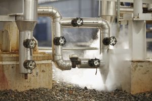
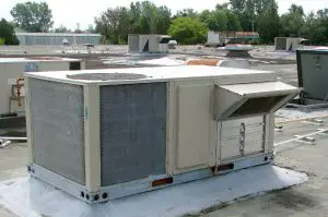
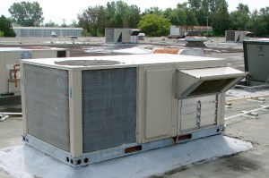
Desuperheater
Desuperheater in Industrial Settings (Image Credit: Komax Systems)

In power generation plants, the role of superheat is significant and hence superheaters are highly recommended. When the temperature of the steam is higher than the saturation temperature, then the state of the steam is referred to as superheated. In this state, the liquid and the vapor are not in equilibrium and can be analyzed from the equilibrium charts.

Superheated steam is preferred during the transfer of heat from one source to another because it acts as an insulator while saturated steam is required for heat transfer processes. In power generation processes, there is a need for both heat insulation and heat transfer, and this is respectively carried out using superheating and desuperheating procedures using superheaters and desuperheaters.

The temperature of the superheated steam is lowered using a heat exchanger that uses a coolant to lower the temperature of the superheated steam and is termed as a desuperheater. In most of the desuperheaters, the fluid that is used for lowering the temperature of the superheated steam is the same as it that of the vapor. Water is the fluid used as a coolant in the case of superheated steam.

DESUPERHEATER TYPES

Desuperheaters are mainly of two types i.e., a direct contact type superheater and an indirect contact superheater which are explained in detail below:

1. Indirect contact desuperheater: In this type of desuperheater, the coolant does not come in direct contact with the superheated vapor. Here the coolant employed will be a liquid or a gas which is allowed to flow through one side of the heat exchanger while the superheated steams pass through the other side. The heat from the superheated steam passes into the coolant through the heat exchanger.   

An example of this type of process is the heat exchange between air which is used as a coolant and hot fluid that is passing through the coils where the air does not come in direct contact with the superheated fluid, but the heat is transferred from the fluid to the air through indirect contact or convection mode of heat exchange.

In these types of desuperheaters, the coolant flowrate or the inlet pressure of the superheated steam can be used for controlling the temperature of the desuperheated steam. It is not feasible to control the flow of superheated steam in these types of processes.

2. Direct contact desuperheater: In this type of superheater, the superheated steam comes in direct contact with the coolant. Usually, the coolant that is used for lowering the temperature of the superheated steam is the liquid form of the vapor. Water is used in most cases as a liquid coolant for superheated steam.

In a direct superheater, a measured quantity of coolant is added to the superheater utilizing the mixing process wherein the coolant mixes with the steam. Once it passes through the desuperheater, the coolant leaves or evaporates from the mixture by absorbing heat from the superheated vapor. In this way, the temperature of the superheated steam is lowered.

The amount of coolant to be added to the process is calculated depending on the steam temperature flowing out of the desuperheater. The desuperheater steam temperature would be set above 3 degrees of the saturation temperature. It is essential in such cases, to keep the superheated steam pressure constant.

DESUPERHEATER PIPING DIAGRAM | DESUPERHEATER PIPING
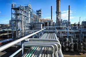
The Ins and Outs of Desuperheaters and the Industries that Benefit 1024x681 1
Desuperheater Piping (Image Credit: Komax Systems)

The desuperheater piping is complex. During the installation of a desuperheater pipeline, the following precautionary measures need to be followed

  • When the same header gives rise to two or more control valves, it should be ensured that there is no instability inflow due to pressure changes.
  • The pipe installed upstream of the control valve should be straight and should have a length 6 times that of the inlet diameter of the pipe body.
  • Downstream to the valve, it is suggested not to rise the piping alignment to avoid the collection of condensates.
  • Further, it is also recommended to protect the temperature probe with insulation where bellows or valves are present.

DESUPERHEATER COILS

Desuperheater coils especially the pack less type has a tube-to-tube design. In this type of design, water flows through the inner tube which has a double wall and the refrigerant flows through the annulus between the tube-to-tube walls. The convoluted structure of the inner tube promotes enhanced heat transfer per unit length and unit area. Further, the convolutions that are offered by the coils promote turbulence which also contributes to the increased thermal efficiency. The rate of heat transfer is enhanced with water and refrigerant in a counterflow arrangement.

DESUPERHEATER BUFFER TANK

In residential apartments or homes, a desuperheater buffer tank is a tank in which the water from the pipeline flows into it enters the water heater. The water is preheated by the desuperheater connected to the buffer tank before it is sent to the water heater. Thereby reducing the load on the water heater.

DESUPERHEATER WORKING PRINCIPLE

Desuperheater or Steam Desuperheater works on the principle of evaporative cooling whereby the liquid water that is sprayed on the superheated steams results in its cooling. On the other hand, the heat absorbed by the liquid coolant helps it in the evaporation process. The heat is obtained from the superheated steam via convection heat transfer. As a result of this process, the steam that comes out from the desuperheater is at a lower temperature.

In a powerplant with a desuperheater, the accumulation of water near the sides of the equipment can occur due to its continuous operation. A hot water spray can be used to remove the water that is accumulated. The hot water spray is maintained at a temperature close to the steam saturation temperature at the exit of the equipment.

STEAM DESUPERHEATER DESIGN

The steam superheater design and sizing are dependent on several requirements with a few being less severe while others having a greater impact on the proper functioning of the desuperheater. To ensure that the desuperheater is performing at an optimal level, the following factors need to be addressed carefully:

1. Ensure that an appropriate amount of cooling is available i.e. ΔTsteam

2. Measure the accurate flow of spray water that is required (Fspray/ Fsteam)

3. Ensure the narrow difference between the steam and saturation temperature (Tsteam – Tsaturation)

4. Fixed range of superheated steam flow rates

5. Fixed range of coolant or water spray flow rates

6. Pressure head of the coolant spray

7. Factors affecting the installation of the desuperheater

These requirements are usually met in applications such as reheat attemperator, bypass process in turbines, and while processing steam for the export. A physical model needs to be in place for the spraying, evaporation, and atomization process of desuperheating. The important rules to be followed for sizing and selection of desuperheater are as follows:

1. It should be ensured that the droplet size is within 250 microns at all operating conditions.

2. The penetration of the spray droplets should be in the range of 15 to 85 percent of the tube diameter. This is to avoid the impingement that can occur. It is a result of cold water hitting the surface of hot bodies or metals or surfaces.

DESUPERHEATER SPRAY NOZZLE DESIGN

A desuperheater spray nozzle helps in controlling the superheat by regulating the cooling water that will be sprayed through the nozzles in the design. It usually consists of a water control valve which helps in attaining a controlled desuperheated flow temperature and negligible pressure drop. The Kv / Cv value and the number of nozzles which is about 6 to 9 will be calculated according to the process conditions.

DESUPERHEATER CONTROL VALVE

Desuperheater is used for carrying out the desuperheating process which is to reduce the temperature of the superheat and to bring back the vapor into a saturated state. A desuperheater control valve helps in controlling the temperature and pressure by adjusting the valve openings depending on the saturation temperature.

DESUPERHEATER REFRIGERATION

In a refrigeration system, the energy from the condensation process of a refrigeration system is left to the ambient environment or discharged to a heat sink. This energy could be used in an effective way for water heating or room heating. To recover the waste heat, the installation of a desuperheater is highly recommended whereby the waste loss can be minimized.

The location of a desuperheater in a refrigeration system is between the compressor and condenser to make use of the energy of the superheated refrigerant. For utilizing the waste heat, a separate heat exchanger should be installed wherein water can be heated using the energy from the superheated gas.

The temperature difference between the discharge from the compressor and the refrigerant condensing temperature will give the available amount of superheat. In case, there is no need for hot water, then this system can be bypassed, and the condenser should have the required condensing power or capability.

Since water is the common fluid that is used in desuperheaters, there are high chances for scaling to take place because as the temperature increases it is difficult to dissolve limestone or calcium carbonate which is the main component of scaling. The allowable temperature of water to limit scaling would be in the range of 65-700C. Further, the use of hard water also increases the chances of scaling. In such cases, it is recommended to use co-current flow to avoid high-temperature risks.

DESUPERHEATER GEOTHERMAL | WATERFURNACE DESUPERHEATER 

A desuperheater which is also termed a water furnace desuperheater or a geothermal desuperheater helps in reducing the costs of water heating and room heating. The excess amount of heat that is absorbed during the summers is used for heating the water. During winter, the heat that is available via a desuperheater is at a much lower cost than a standard domestic water heater.

The heat that is rejected is made use of an in desuperheater hot water superheater. It is recommended to have a buffer tank or a pre-tank which would help in preheating the water.

DESUPERHEATER PUMP

In residential or domestic water heating using desuperheaters, the heat during the summers is used for heating the water. It is essential to have a desuperheater pump that would help in pumping the water to the buffer tanks before it is available for the desuperheating process. During winter, the heat that is available via a desuperheater is at a much lower cost than a standard domestic water heater.

It is essential to note if the sizing of the pump is appropriate for heating purposes. The desuperheater uses the heat energy that is being removed while its main purpose is to cool the room.

DESUPERHEATER COST

The desuperheater cost which can be installed for residential purposes is very much affordable and costs about $1350 approximately. For installing a desuperheater, it is essential to have a heat pump which is included in the total cost that is mentioned. A heat pump with a coefficient of performance of value 4 would help in saving 75% which is a great investment when it comes to the residential or domestic water heater.

DESUPERHEATER AND ATTEMPERATOR

A desuperheater is used for removing the heat that is present in the superheat thereby reducing the temperature of the superheat close to saturation temperature or below. An attemperator is used for regulating the steam temperature of the boiler. A desuperheater is usually located downstream from the boiler where saturated steam would be useful. While an attemperator is allocated close to the boiler where high temperatures could have an impact on the walls or surfaces which would, in turn, have an impact on the process operation.

VENTURI DESUPERHEATER | VENTURI TYPE DESUPERHEATER

Venturi desuperheaters or annual desuperheaters help in reducing the temperature of the superheated steam by bringing it in direct contact with water. Here evaporative cooling takes place. They can be used in different environmental conditions and can be vertically or horizontally installed. When they are vertically installed, there is a substantial increase in the turn-down ratio.

These types of superheaters prevent the accumulation of water, which is not vaporized, which is a major drawback in most of the desuperheaters. Here the droplets of water that fail to vaporize will be sent back to the high-temperature region where they will be completely vaporized.

The advantage of using Venturi desuperheater is that they can be installed either vertical or horizontal. Further, they are built of heavy materials and do not have any moving parts which could interfere with their proper functioning. They are generally used in controlling temperatures of fluid that are sent to the evaporator or used in heat exchangers especially at the entrance to reduce the dimensions and cost.

LNG DESUPERHEATER

In a propane refrigeration system, water is used for condensation of the propane after the compression stage. It is recommended to use two propane desuperheaters which work on the same principle that is to reduce the temperature of the superheated steam. Such a system should also be equipped with 6 propane condensers in parallel orientation. Shell and tube heat exchangers are usually used in this type of system.

FREQUENTLY ASKED INTERVIEW QUESTIONS AND ANSWERS

1. How does a desuperheater work in a boiler? | Function of desuperheater in a boiler

Desuperheaters are used in boilers to reduce the temperature of the superheated steam that is produced in the superheater for electricity generation. The desuperheater helps in lowering the high temperature of the steam to low temperatures that will help in safely carryout the other process operation. The temperature of the superheated steam is controlled by bringing the steam in direct or indirect contact with a coolant. The injected water is then allowed to evaporate.

The two main reasons for lower the steam temperature are as follows:

1. The downstream equipment is designed to handle lower temperatures hence it is essential to lower the temperature of the steam.

2. To ensure that a controlled temperature is maintained for processes that required a specific temperature.

2. Why is a steam desuperheater installed after a turbine and what is the function of a surface condenser installed after it?

A steam desuperheater is used for lowering the temperature of superheat by bringing the superheat in direct or indirect contact with a coolant.

The superheated steam loses some of its heat in the turbine though not all of it. The remaining superheat which when exposed to a lower pressure results in entrained droplets of water flashing into steam which causes water hammer and other conditions.

The job is completed using the surface condenser which removes all the steam from the entry point and below the saturation so that the steam is condensed can be used for other purposes which include recycling to the boiler or other load extraction processes.

3. How is desuperheating of steam in superheaters and reheaters in a steam power plant considered a loss inefficiency?

In a desuperheater, the heat from the steam is not being used and contributes as waste heat which needs to be recovered through integrated systems. Further, the steam temperature at the outlet of the desuperheater is lower than before. Hence, this results in a loss of efficiency.

For systems with reheating, the heat that is obtained from coal or any other fuel is always less than the heat that is available for the steam. A reheater can never attain 100% efficiency. As a result, the available efficiency will be multiplied by the actual efficiency and this will lower the efficiency value.

4. How much water is required to desuperheat steam?

The amount of water required in a desuperheater depends on the amount of superheat or degrees of temperature that need to be lowered and depends on the pressure of the steam header. It can be calculated using an enthalpy balance whereby the summation of the enthalpy of steam and water is equal to the heat that is present in the exit stream. For carrying out this calculation, a steam chart would be handy.

Since the heat capacity of steam and the heat of vaporization is noted to be 0.5BTU/lbf and 1000 BTU/lbf respectively, the amount of water that is required for desuperheating would be less than the amount that one would guess. The water that is used for desuperheating should be demineralized to avoid solid build-up in the desuperheater.

In short, the amount of water required for desuperheating superheated steam depends on the temperature of the steam and the degrees of temperature to be lowered.

5. How does a pressure-reducing desuperheating system work in a thermal power plant?

In a pressure-reducing desuperheating system which is also known as a PRDS system, the required steam quality of specific quantity, temperature and pressure is released. The steam that is used in this system is either fresh steam or steam that is bled. This process is carried out using attemperating water that is obtained from the condensate water. The two fluids are mixed at controlled measures to obtain the steam at specific pressure and temperature.

6. What keeps a superheater from being damaged by heat before a boiler makes steam?

The reason why the superheater is not affected by the heat is that the steam that flows through the superheater cools the metal surfaces and other parts thereby reducing damages to the superheater.

7. What is the maximum velocity of water through the spray nozzle for the desuperheater?

The maximum velocity of water through the nozzle is about 46 to 76 meters per second. The turbulence is noted to be low when the minimum velocity of water is low, such that droplets of water get suspended from the steam and fall out.

8. Desuperheater Energy Balance

It can be calculated using an enthalpy balance whereby the summation of the enthalpy of steam and water is equal to the heat that is present in the exit stream. For carrying out this calculation, a steam chart would be handy.

Hsteam + Hwater = Qexit stream

9. what is the use of a desuperheater in a superheater?

Desuperheaters are used in boilers to reduce the temperature of the superheated steam that is produced in the superheater for electricity generation. The desuperheater helps in lowering the high temperature of the steam to low temperatures that will help in safely carryout the other process operation.

10. Turn off desuperheater in winter

It is recommended to turn off the desuperheater during the winter because there are chances of absorbing heat from the pipeline carrying hot water, thereby reducing the efficiency of the system to heat the house during the winters.

To have a better understanding of Desuperheaters, it is recommended to read on Superheaters
Forming Process: 31 Important Factors Related To It

1 5

keyword

Forming is type of manufacturing process used very widely through out the world and is one of the old technique. Following are the points we are going discuss in detail in this article:

Content

What is forming? | Fundamentals of metal forming processes

Forming/ Metal forming is a process in which material deforms plastically to get the required shape by application of force in such a way that the stress generated should be greater or equal to yield stress, and simultaneously, it should be less than the ultimate stress of the material.

\\sigma y\\ \\leq \\sigma \\ \\leq \\sigma u

Types of forming process | Forming process in manufacturing | Bulk metal forming processes | Metal forming processes | Forming operations | Type of forming operations | Different types of forming | | Classification of metal forming process | Types of plastic forming

Metal forming:

1) Bulk metal forming: 

  1. Forging
  2. Rolling
  3. Extrusion 
  4. Wire forming

2) Sheet metal forming

  1. Bending
  2. Deep cup drawing
  3. Shearing
  4. Stretching
  5. Spinning

3) Advanced metal forming

  1. Super plastic forming
  2. Electroforming
  3. Fine and banking operation
  4. Hydro forming
  5. Laser forming
  6. Powder forming

Microstructure evolution in metal forming processes

When metal forming is carried out, the material goes under very high stress to change it shape. The microstructural change in the material take place. But the formation of crystals will only re arrange if it is hot work, that is worked above recrystallization temperatre. That is the material is heated above its recrystallization temperature and forming is carried out.

Temperature in forming processes | Hot metal forming processes | Cold metal forming processes | Effect of temperature on metal forming process

  • Temperature stands to be a very important factor in the manufacturing process, as the material properties are a function of the temperature.
  • The working in forming process is divided into three parts on basics of temperature:
  • 1. Cold working
  • 2. Warm working
  • 3. Hot working
  • Before defining the above points, let us know what Recrystallization temperature is.

Recrystallization temperature:

  • The temperature at which the material will reform the arrangement of its crystal is known as recrystallization temperature.
  • It is unique value for each material
  •  Lead, Tin, Zinc, and Cadmium is the material whose recrystallization temperature is equal to the room temperature and hence work perform on this materials is always hot work.
  • Recrystallization temperature ranges from 0.5 to 0.9 times of melting temperature of the material.

Cold working:

  • When work is done on the material, when material’s temperature is below the Recrystallization temperature, such work comes under the category of cold working.
  • The amount of force and energy required in cold working is very high.
  • The accuracy is quite good in cold working as compared to others.
  • Properties like Strength and Hardness increase. 
  • While the properties like malleability and ductility reduce.
  • Friction acting in cold working is low.

Warm-working:

  • When work is done on the material at a temperature above cold working but less than the recrystallization temperature, it comes under the category of warm working.
  • It is preferred over cold working when the amount of force applied is less.

Hot working:

  • When work is done on the material, material’s temperature is greater than the Recrystallization temperature, such work comes under the category of hot working.
  • The amount of force and energy required in hot working is less.
  • The accuracy maintains poor in hot working as compared to others.
  • Properties like Strength and Hardness decrease.
  • While the properties like malleability and ductility increase.
  • Friction acting in hot working is high.

Types of cold forming process

Cold forming techniques: squeezing process, bending process, drawing process, and shearing process. 

Squeezing process consist of:

  • Rolling process,
  • Extrusion process,
  • Forging process,
  • Sizing process

Bending process consist of:

  • Angle bending process,
  • Roll bending process,
  • Roll forming process,
  • Seaming process,
  • Straightening process
  • Shearing process consist of:
  • Sheet metal shear-cutting process,

Blanking.

  • Drawing process consist of:
  • Wire drawing process,
  • Tube drawing process,
  • Metal spinning process,
  • Sheet metal drawing process,
  • Ironing process

Friction and lubrication in metal forming process | Friction in metal forming process

  • friction in metal forming take place due to close contact of work piece surface and the tool (die, punch) at high pressure (Also high temperature for some operation).
  • This high pressure, high compressive stress and also friction plays a very important role in forming of the product.
  • But over 50% of energy is required to overcome tis friction.
  • Surface quality is retarded, the tool and die life is reduced.
  • To overcome such undesirable effects lubrication is introduced

To overcome the friction lubrication is carried out:

Lubrication in metal forming process | Types of lubricants used in metal forming

Metal forming uses lubrication: water-based, oil-based, synthetic and solid film

  • Water based: they good for cooling purpose but are has less lubricity. They are mostly used for high speed application.
  • Oil-based: It overcome draw backs of water based lubricant but you lack additive solubility.
  • Synthetic: with solubility it also provides good lubricity.
  • Solid film: can be used with or without oil/water, mostly used for high pressure, low speed and low temp application.

Advantages and disadvantages of metal forming process

Advantages:

  • Material wastage is negligible or zero (As no shear/ cutting action involved).
  • Grain can be oriented in required direction
  • By cold working strengthens and hardness is increasing, while by hot working the ductility and malleability increases.

Limitations:

  • Force and energy required is very high
  • Automation is required, therefore it is costly
  • Except forging all other process can produce uniform cross section.
  • Crossover and undercut are difficult to produce.

Applications of metal forming process

  • Channels of direct shape. 
  • Seamless tubes
  • Turbine-rings.
  • Hardware products like nail, hails
  • Agricultural tools used for sawing and cutting.
  • Military products
  • Automobile structure parts doors, outer body shield. 
  • Different plastic products

Rolling 

Rolling is a process when the required shape is obtained by passing the material through rollers. This rollers are places with distance between them, which is define by the required thickness of the output product. As material is forced to pass through this gap the high force is also applied by the rollers. The number of rollers depends on application of force.

FORMING PROCESS
rolling process

Rolling is carried out by the following methods:

1.) Hot rolling

2.) Cold rolling

3.) By application of front and back tension

Roll forming (hot)

  • Hot rolling is a rolling process (also known as hot working) when the material is heated above its recrystallization temperature before passing it through the rollers.
  • Malleability and ductility increase while strength and hardness decreases
  • Surface finish and dimension accuracy is poor
  • Force and energy required is less as compared to cold rolling
  • Friction is high

Roll forming (cold)

  • Cold rolling is a rolling process (also known as cold working) when the material is heated below its recrystallization temperature before passing it through the rollers.
  • Malleability and ductility decreases while strength and hardness increases
  • Surface finish and dimension accuracy is excellent
  • Force and energy required is more as compared to hot rolling
  • Friction is low

Types of roll forming machine

  • Two-high rolling-mills
  • Three-high rolling-mills
  • Four-high rolling-mills
  • Cluster rolling-mill
  • Planetary rolling-mill
  • Tandem rolling-mill

Sheet metal forming processes and applications | Sheet metal forming processes and die design | Sheet metal roll forming process | Sheet metal forming processes and applications

In forming sheet metal operation the material is deform plastically and no cutting action is carried out.

The force applied in sheet metal forming operation is more than the yield stress so as to carry the deformation but less than the ultimate stress as not cutting action in carried out in forming process.

\\sigma y\\ \\leq \\sigma \\ \\leq \\sigma u

Different types of sheet metal forming processes | Types of sheet metal forming process | Types of sheet metal forming processes

  • Bending
  • Deep cup drawing
  • Shearing
  • Stretching
  • Spinning

Bending

Bending is a sheet metal forming operation is where metal is bent in the required direction by applying force with the help of punch and die components. When bending occurs, the outside layers of the sheet go through tension while the inside layer goes through compression. If the stretching is excessive, there might be a chance of shifting the neutral plane towards the center of curvature.

2 3
bending

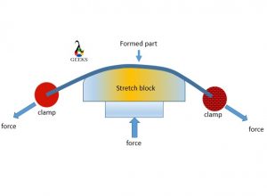
Stretch forming | Types of stretch forming

It is sheet metal forming process in which the selected sheet is stretch and bended continuously over a die to get the required shape. It acquires the shape of the die.

3 2
stretch forming

Types of the stretch forming:

  • Longitudinal stretch forming
  • Transvers stretch forming

Deep drawing metal forming process

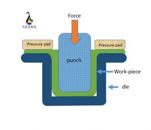
Manufacturing of cup from a raw sheet blank with the help of the punch and die is called deep drawing or cup drawing process, Here the material is deformed plastically to get the required shape. It is a sheet metal forming operation hence no cutting action. Punch is used to apply the force to create plastic deformation of the material. And it gets the shape of the die and punches while going through series of bending, stretching, straighten up to produce a vertical deformation wall of a deep-drawn component.

4 2
deep dawing

Guerin process metal forming

guerin process metal forming is a subpart sheet metal forming process. In this process the sheet metal is stamped with help punch to get desirable result. It is simple shaping of sheet metal by stamping process.

Metal press forming process

Metal press forming is very simple process in which sheet metal is hold with help of the clamps and shaped with help die and punch. It is same as the stamping process.

Spinning process in metal forming | Spinning process in sheet metal forming

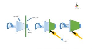
In this process the disc of the metal sheet is used as raw product. It is clamp over the spinning machine against the mandrel. The disc of sheet is pressed against the high speed rotating mandrel with help of the press tool. The symmetric objects are manufactured in this process. It can be carried out on the CNC machine.

6 1

Roll forming process in sheet metal

Roll forming in sheet metal is a process when the required shape/size is obtained by passing the sheet metal through rollers. This rollers are placed with distance between them, which is define by the required thickness of the output product. As material is forced to pass through this gap the high force is also applied by the rollers. The number of rollers depends on application of force

Types of roll forming

  • Two-high rolling-mills
  • Three-high rolling-mills
  • Four-high rolling-mills
  • Cluster rolling-mill
  • Planetary rolling-mill
  • Tandem rolling-mill

Defects in sheet metal forming process

Defects in sheet metal:

Wrinkle: the folding create at inside of the deep drawn component is called wrinkle. It can be eliminated by applying blank holding force along strip plate.

Earing defects: The folding created at the flange end of the deep drawn component is called as the earing defect. It is generated because of circumferential compressive stress or anisotropic properties of material. 

It can be eliminated by cutting the material after deep drawing operation by trimming process. The amount of material trimming comes under the trimming allowance.

Scratches: In a deep drawing process because of the friction present between component and the die scratches are generated and it reduces surface quality. It can be eliminated by proper lubrication.

Corner crack or fracture: corner crack or fracture are generated at the bottom of the deep drawn components because of thinning of material and stress concentration. 

Orange peel: When annealing of the deep drawn component is done above recrystallization temperature it is observe that the grain get expanded independently and produce coarse size of grain. Which has some structure like peel of orange. Therefore it is called as orange peel.

Advantages and disadvantages of sheet metal forming process | Advantages of sheet metal forming process

Advantage:

  • Production rate is high
  • Minimum waste
  • Uniform density
  • Simple process
  • High strength
  • Good surface finish

Disadvantage:

  • High force required
  • Heavy machineries
  • Automation required
  • Somewhat poor in maintain accuracy

Forging

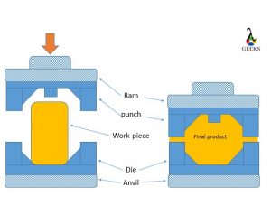
Forging is a process in which material if deforms plastically to get the required shape by applying high compressive force with the help of hammers. The compressive force is applied at a particular location several times to get the final product.

7 1
forging

Mostly forging uses a hot working process.

Extrusion | Extrusion metal forming process | Extrusion process in metal forming

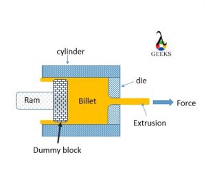
Extrusion is a process where a billet is placed inside the stationary cylinder with one end attach to opening with die (Output shape) and another end has a ram to apply the force. 

When the force is applied to a solid billet, it acts in a hydrostatic compressive manner.

At one point, this value will reach the flow stress value of the material, where the entire solid material will become extremely soft, like a gel, and will flow through the die, with the shape of the die.

8 1
Extrusion

Extrusion types:

1) Forward/direct extrusion: Hydrostatic extrusion.

2) Backward/ indirect extrusion: Impact extrusion or hollow back extrusion.

Wire drawing | Drawing metal forming process

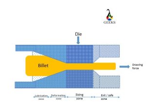
Wire drawing is a process where the billet is given the shape of required output by pulling it through a die rather than Appling force from backward as the extrusion.

A typical wired drawing can de dived in four zone.

wire drawing
wire drawing

Zone 1: Deformation Zone

The entry diameter of the zone is equal to the rod diameter of the zone, while the end diameter is the diameter of the wire needed to be. Therefore whatever deformation is required to convert the rod into wire takes place in this zone. It is known as the deformation zone. The total included angle of the stented surface of the deformation zone is called as die angle or deformation angle.

Zone 2: Lubrication Zone

This zone is used to supply lubricant to reduce friction and let the process carry out smoothly. If the lubrication is not provided, it dull, rough, and unpleasant surface finish of the wire.

Zone 3: sizing zone

This zone is just used to maintain the same load for some time to convert elastic deformation into permanent plastic deformation.

Zone 4: Exit or Safety zone

This zone is used for collecting high-pressure and high-temperature lubricants.

Punching metal forming process

Punching is process in which punch is used to apply the force on the work piece to get required output and the result may be in form of the cutting/ shear action depending upon a material. It is mostly used to create holes in a metal sheet.

Advanced metal forming processes | Advanced metal forming process

  • Super plastic forming
  • Electroforming
  • Fine and banking operation
  • Hydro forming
  • Laser forming
  • Powder metal forming process

Powder metal forming process

Power metal forming is process in which raw material is in powder form and is well mix for desired output product composition. The powder is push into the die and the punch is used to apply the force and hold it for a time. To increase the density of the product the heat application is also introduced. It is used to manufacturing of self-lubricating bearing.

Blanking metal forming process

Blanking is the specialized precision metal forming process that includes extrusion in cold manner and advanced stamping techniques. It gives clean and good dimension accuracy products, but cost is very high.

Mostly used to manufacture automobile and electronic parts

Types of plastic for vacuum forming

  • Acrylonitrile Butadiene Styrene
  • Acrylic – Perspex
  • Co-Polyester
  • Polystyrene
  • Polycarbonate
  • Polypropylene
  • Polyethelene

FAQ’S

What are the different metal forming processes | Types of metal forming process | what are the different types of forming | Metal forming process example

1) Bulk metal forming: 

  • Forging
  • Rolling
  • Extrusion 
  • Wire forming

2) Sheet metal forming

  • Bending
  • Deep cup drawing
  • Shearing
  • Stretching
  • Spinning

3) Advanced metal forming

  • Super plastic forming
  • Electroforming
  • Fine and banking operation
  • Hydro forming
  • Laser forming
  • Powder metal forming process

Sheet metal forming process

  • Bending
  • Deep cup drawing
  • Shearing
  • Stretching
  • Spinning

Hot metal forming processes

  • When work is done on the material at a temperature greater than the Recrystallization temperature, such work comes under the category of hot working.
  • The amount of force and energy required in hot working is less.
  • The accuracy maintains poor in hot working as compared to others.
  • Properties like Strength and Hardness decrease while the properties like malleability and ductility increase.
  • Friction acting in hot working is high.

Metal forming process in automobile industry

Mostly sheet metal forming is used in automobile industry.

What are the defects in metal forming process

Rolling Defects:

Spreading: In a rolling when material spread along the width such defect is called spreading. Generally when thickness of the strip is very high and width is less material spread along the width direction

Alligatoring: Because of the excessive shear along a shear plane of a raw material strip sometimes it gets fracture from the center and creates a similar structure as the mouth of the alligator. Therefore it is called as the alligatoring defect.

Waviness: Because of the anisotropic property of the engineering material a waviness I generated on the rolled components, such defect is called as waviness defect.

Extrusion defects:

Bamboo defects: soft crack along the surface of the component.

Fish Tail: It occurs when hot extrusion is carried out with impurities in the billet. It is also called as pipping defect. It create sink hole at the end of billet.

Center Burst: Center burst are the internal cracks present in the product. 

Sheet metal forming defects:

Wrinkle: the folding create at inside of the deep drawn component is called wrinkle. It can be eliminated by applying blank holding force along strip plate.

Earing defects: The folding created at the flange end of the deep drawn component is called as the earing defect. It is generated because of circumferential compressive stress or anisotropic properties of material. It can be eliminated by cutting the material after deep drawing operation by trimming process. The amount of material trimming comes under the trimming allowance.

Scratches: In a deep drawing process because of the friction present between component and the die scratches are generated and it reduces surface quality. It can be eliminated by proper lubrication.

Corner crack or fracture: corner crack or fracture are generated at the bottom of the deep drawn components because of thinning of material and stress concentration. 

Orange peel: When annealing of the deep drawn component is done above recrystallization temperature it is observe that the grain get expanded independently and produce coarse size of grain. Which has some structure like peel of orange. Therefore it is called as orange peel.

Is the panel beating metal forming process still in use nowadays

Yes, panel beating is still used now a days. Mostly in small automobile shops to recovery the damage part.

What factors influence formability in metal forming

Properties like, ductility, malleability and formability are important in metal forming.

Is there any difference between sheet metal working process and sheet metal forming process

Yes, in sheet metal work we involve cutting/ shearing apart from forming action but in sheet metal forming the sheet does not go under cutting action. Sheet metal forming is a subpart of metal working.

What is the difference between forming and shaping processes

Forming is the process where the billet is converted and form in a particular shape with the application of compressive force. The volume changes is negligible.

Shaping is the process where the material is cut and machined to get the required output product. The sharp cutting tools are used to machine the material. The volume change take place.

What are some common uses for sheet metal

In automobile, Aircrafts covering.

In domestic appliances: iron covering, washing machine body, fan blades, cooking utensils etc.

For more Article’s related mechanical engineering, visit our website

Read more about Quasi-Static Process.

Babcock And Wilcox Boiler: 11 Facts You Should Know

800px Babcock and Wilcox boiler Heat Engines 1913 1 300x233 1

Content

Keynotes

Babcock and Wilcox boiler | what is Babcock and Wilcox boiler

  • Stationary
  • Water tube
  • Externally fired

Babcock and Wilcox boiler parts

  • Drum or shell
  • Superheater
  • Water tubes
  • Upper and lower header
  • Furnace
  • Baffles
  • Grates
  • Fire door
  • Anti priming pipe
  • Mud box
  • Man hole

Babcock and Wilcox boiler accessories & Mountings

  • Water level indicator (Indicate water level)
  • Steam Stop valve
  • Safety valve (To reduce pressure)
  • Superheater (Increase temperature)
  • Pressure gauge (Pressure measurement)

Why are the tubes of water tube boilers kept inclined?

The water tubes are joined with the water steam drum. The water tubes are installed inclined with the boiler to improve heat transfer and get other benefits. The water tubes is kept 15° angle of inclination. The tube diameter of the water tubes installed in this boiler is approx. 10 cm.

The tube inclination is increasing  the convection heat transfer in the tube.

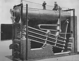
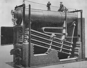
Babcock and Wilcox boiler diagram | Babcock and Wilcox boiler easy diagram | Babcock and Wilcox boiler images | Babcock and Wilcox boiler schematic diagram

Babcock and Wilcox boiler
Babcock and Wilcox Boiler Credit Wikipedia
Babcock and wilcox schematic
Babcock and Wilcox Schematic
Image Credit Research gate Dr. Ravindran S., Shanmugam

Working of Babcock and Wilcox boiler

Lets’s learn the working of the Babcock and Wilcox boiler with details and stepwise.

  • The water is stored inside the drum. Then, the fluid initiates flowing from the steam –water drum to the incline water tubes (through the lower header).
  • The solid fuel burning in the furnace generates the hot flue gases passing over the water tubes. The water tube contains water in it which is get heated because of hot flue gases. Here, the baffles are very helpful to increase heat transfer. The hot gases pass through the zigzag motion due to baffles.
  • The water inside water tubes absorbs heat from hot flue gases and changes the phase from water to steam.
  • The produced steam inside the water tube will travel to the top and collected inside the topmost portion of the drum.
  • The function of an anti priming pipe is to reduce moisture content present in the steam. There are some holes inside the anti priming pipe, which is useful to lower the moisture. After separating moisture content, this pipe transfers the high pressure steam to the superheater for next steps.
  • The function of a superheater is to raise the temperature of the steam to make it suitable for power generation. Then, the super-heated steam is supplied to the steam stop valve pipe.
  • The steam from the superheater is either taken out or stored in the drum for another process. If the steam is taken out from the boiler, it is supplied to the turbine for power generation. The steam of boiler can be used for process heating purposes also.

Advantages of Babcock and Wilcox boiler | advantage of Babcock and Wilcox water tube boiler

The advantages of Babcock and Wilcox boiler are discussed in detail :

  • The efficiency of this boiler is more compared to others. The efficiency is expected around 60 to 80%
  • The generation of steam is higher in this boiler. It is approximately 20,000 to 40,000 kg of steam in one hour (Pressure range between 10 to 20 bar).
  • This boiler is easily maintainable compared to others.
  • It is easy to change the faulty tube in Babcock and Wilcox boiler.
  • The tube expansion and tube contraction cannot create problem in this boiler. The water drum and water tubes are loosely connected in the brick wall so that it is easy to expand and contract tubes during heat transfer.
  • The loss due to drought in Babcock and Wilcox boiler is very less.
  • The boiler inspection is convenient during boiler working.
  • It is easy to clean and repair every part of the Babcock and Wilcox boiler due to its better accessibility.
  • It is possible to obtain temperature and steam quickly in this boiler. Therefore, it is suitable to meet the quick demand for steam.
  • It can deliver highly dry steam even if the water supply is not proper compared to other boilers.
  • It requires less floor area per steam generation as compared with the fire tube boiler.

Disadvantages of Babcock and Wilcox boiler

There are some disadvantages of the Babcock and Wilcox boiler as discussed below in detail,

  • The water requires for the boiler should be very pure. Even a few impurities in the water can cause scale formation in water tubes. This scale formation results in a reduction in steam generation due to bursting and overheating. Before supplying water to the boiler, water treatment should be carried out to minimize the impurities.
  • It is required to monitor the water level continuously inside the boiler. If the feedwater level falls below the limit for few seconds, it can cause the overheating of tubes.
  • The Babcock and Wilcox boiler’s size is large compared to other boilers, resulting in the boiler’s maintenance cost.
  • The brick structure is required in this type of boiler, which is not necessary for other boilers.

Application of Babcock and Wilcox boiler | uses of Babcock and Wilcox boiler | Babcock and Wilcox boiler uses

This boiler is a stationary water tube boiler, so that it is normally utilized in stationary applications.

This type of boiler is utilized to develop higher pressure steam. This steam is utilized to electric power production.

Babcock and Wilcox boiler parts | Babcock and Wilcox water tube boiler | Babcock and Wilcox boiler model

There are many big and small parts in Babcock and Wilcox boiler. Out of them, some of the main components are listed and described as below,

Shell or Drum or water shell:

It is a cylindrical portion on top of the boiler. This drum is filled with water. The water level is maintained around 2/3 rd of the drum. The steam and water both stored in the drum during the operation of the boiler.

Water tubes (water pipes):

The water tubes are connected with the drum. The water tubes are installed inclined with the boiler to improve heat transfer and get other benefits. The water tubes is kept 15° angle of inclination. The diameter of the water tubes used in this boiler is about 10 cm.

Superheater:

The function of a superheater is to raise the temperature of the steam to make it suitable for power generation. Then, the super-heated steam is supplied to the steam stop valve pipe.

Furnace:

The Babcock Wilcox boiler is externally fired. The furnace of this boiler is built outside of the boiler structure. This furnace is built below the upper header.

Baffles :

The function of the baffles is to make gases passes over the tubes properly. It is also widely called a deflector. These baffles are made of bricks. The baffles are also useful to increase the effective contact area and time of contact between the water tubes and the hot flue gases.

Grate:

The grate is the cast iron made setup that is used inside the furnace. The solid fuel is spread over the grate for proper burning.

Fire Door:

The fire door is utilized to put fuel into furnace of the boiler. The solid fuel is generally provided through the fire door.

Anti -Priming Pipe (To remove moisture):

The function of an anti priming pipe is to reduce moisture content present in the steam. There are some holes inside the anti priming pipe, which is useful to lower the moisture.

Upper Header and Lower Header:

There are two headers in the Babcock and Wilcox boiler. One is the upper header, and the second is the lower header. The upper header and more downward header are joined with the drum through the water tubes.

The function of the upper header is to transfer the steam–water mixer to the drum. This header is joined to the front of the boiler.

The use of the lower header is to transfer fluid from the back end of the steam-water drum to the water tubes.

Mud Box:

The function of the mud box is to take mud and impurities from the water. It is installed below the lower header. Thus, the collected dirt is disposed of properly.

Man Hole:

The utility hole is a very important part of a boiler because it is the entry gate of a person to enter into the boiler. One can go inside the boiler and do cleaning and maintenance. The manhole should be kept close during boiler operation.

Blow Off Pipe:

The function of the blow-off pipe is used to take out all mud from the mud box. It is also draining water if found in an excessive way.

Supports:

The drum is installed with two supports because the drum carries water. In addition, the weight of the drum is high due to water storage. Therefore, supports are needed for the drum.

Babcock and Wilcox boiler specification

This boiler is available in the range of specifications. The common specification of the Babcock and Wilcox boiler is given below.

  • The thermal capacity of the boiler: 4 to 35 tons per hour
  • Pressure range: 1 to 2.5 MPa
  • The steam temperature at the output: 184 to 350 ℃
  • Acceptable fuel: Solid fuels like coal, woods etc.
  • Applications: Power industries, Petroleum industries, chemical industries for process heat, pharma and textile industries for process heating etc.

Babcock and Wilcox boiler accessories

The safety and performance of the boiler can be maintained with mountings and accessories. Mountings and the accessories of this boiler are discussed as below,

List of the mountings and accessories

  • Water level indicator (Indicate water level)
  • Steam Stop valve
  • Safety valve (To reduce pressure)
  • Superheater (Increase temperature)
  • Pressure gauge (Pressure measurement)

Water Level Indicator (Indicate water level)

The level of water inside the boiler should be maintained properly for efficient working of the boiler. The water level indicator indicates the how much water present inside the boiler at a time. The boiler operator continuously read the water level in the water level indicator.

Pressure measuring instrument

It is utilized to read the steam pressure in the boiler. The boiler operator continuously observes the pressure gauge during boiler operation.

Safety Valve

It is the most important device according to boiler safety. The safety valve installed on the steam chest. If the pressure inside the boiler will increase at the desired level, then this valve will open and release the pressure.

Superheater:

The function of a superheater is to raise the temperature of the steam to make it suitable for power generation. Then, the super-heated steam is supplied to the steam stop valve pipe.

Steam Stop Valve

A steam stop valve in this boiler is work to maintain the flow of produced steam. It is also useful to stop the steam output whenever required. It is one of the largest valve in the Babcock and Wilcox boiler. It is installed between the boiler and the main steam outlet line.

Babcock and Wilcox boiler pressure

The pressure inside Babcock and Wilcox boiler depends on the specification of the boiler. The operating pressure inside this type of boiler is generally in the range of 11.5to 17.5 bar.

Babcock and Wilcox boiler principle | construction and working of Babcock and Wilcox boiler

The water is kept in the water-steam drum. Then, the fluid starts leaving from the water-steam drum to the incline water tubes (through the lower header).

The solid fuel burning in the furnace generates the hot flue gases passing over the water tubes. The water tube contains water in it which is get heated because of hot flue gases. Here, the baffles are very helpful to increase heat transfer. The hot gases pass through the zigzag motion due to baffles.

The water inside water tubes absorbs heat from hot flue gases and changes the phase from water to steam.

The produced steam inside the water tube will travel to the top and collected inside the topmost portion of the drum.

The function of an anti priming pipe is to reduce moisture content present in the steam. There are some holes inside the anti priming pipe, which is useful to lower the moisture. After separating moisture content, this pipe transfers the high pressure steam to the superheater for next steps.

The function of a superheater is to raise the temperature of the steam to make it suitable for power generation. Then, the super-heated steam is supplied to the steam stop valve pipe.

The steam from the superheater is either taken out or stored in the drum for another process. If the steam is taken out from the boiler, it is supplied to the turbine for power generation. The steam produced from Babcock and Wilcox can be utilized for process heating applications also.

FAQS

Where Babcock and Wilcox boiler is used ?

The Babcock and the Wilcox boiler is generally used in the following applications,

Applications: Power industries, Petroleum industries, chemical industries for process heat, pharma and textile industries for process heating etc.

Power generation is a wide application of this boiler.

Who founded Babcock ?

Hero was a mathematician and scientist in greek. He has developed equipment working on the steam. Later on, it became known as the steam engine. Hero’s science is used to build the water tube boiler. Stephen Wilcox is the person who developed this boiler.

Which types of fuel can be used in Babcock and Wilcox boiler?

There are many fuels can be used for Babcock and Wilcox boiler. However, the coal is most widely used fuel for this boiler.

What will happen if the heat exchanger tube of the Babcock and Wilcox boiler is replaced by a cube?

A heat exchanger tube provides a more effective heat transfer area as compared to a cube. If a cube is used instead of a heat exchanger tube, the performance of the boiler will be decreased

Why are the tubes of water tube boilers kept inclined? Justify

The water tubes are joined with the water steam drum. The water tubes are installed inclined with the boiler to improve heat transfer and get other benefits. The water tubes is kept 15° angle of inclination. The tube diameter of the water tubes installed in this boiler is approx. 10 cm.

The inclination of the tube is encouraging the convection heat transfer in the tube.

For More Articles on Mechanical Engineering , Click Here

Diesel Cycle: 17 Important Factors Related To It

Pv 300x182 1

Key highlights:

Content:

Diesel Cycle

The Diesel engine came into existence by Rudolph Diesel in 1892, and it was somewhat modification of the SI engine by eliminating the spark plug and introducing a fuel injector. The idea was to overcome the problem regarding air-fuel mixture compression and replace it with just air compression and suppling fuel at high-pressure, high-temperature air for the combustion process.

Diesel cycle definition

The diesel cycle or Ideal diesel cycle is the power-producing cycle that generates the power stork at constant pressure. It is used in Reciprocating internal combustion engines with fuel as Diesel.

Diesel combustion cycle

The work input required in the diesel cycle is for compression of air, and the work output is obtained by the combustion of fuel causing the power stroke. Combustion is considered to be at constant pressure (Isobaric process) resulting in increase of volume and temperature.

The process starts with sucking the atmospheric air into the cylinder, then the compression process takes place, resulting in increased pressure and temperature of the air.

At the end of this stage, the air is at a high temperature and high pressure, just a bit before the end of the compression stage, the fuel is added through the fuel injector. as the fuel comes in contact with this high-temperature, high-pressure air, it self-ignites, and the combustion stage occurs.

Combustion of enriching fuel results in the generation of power, which results in the power stroke, i.e., the piston is pushed back with high, resulting in work output than the last stage, i.e., exhaustion takes place, to let out the burnt gas in the cylinder.

And then, the process is repeated.

To get continuous output, we are required to arrange the number of cylinders rather than just one.

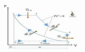
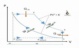
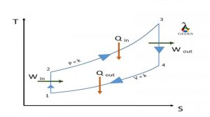
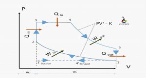
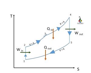
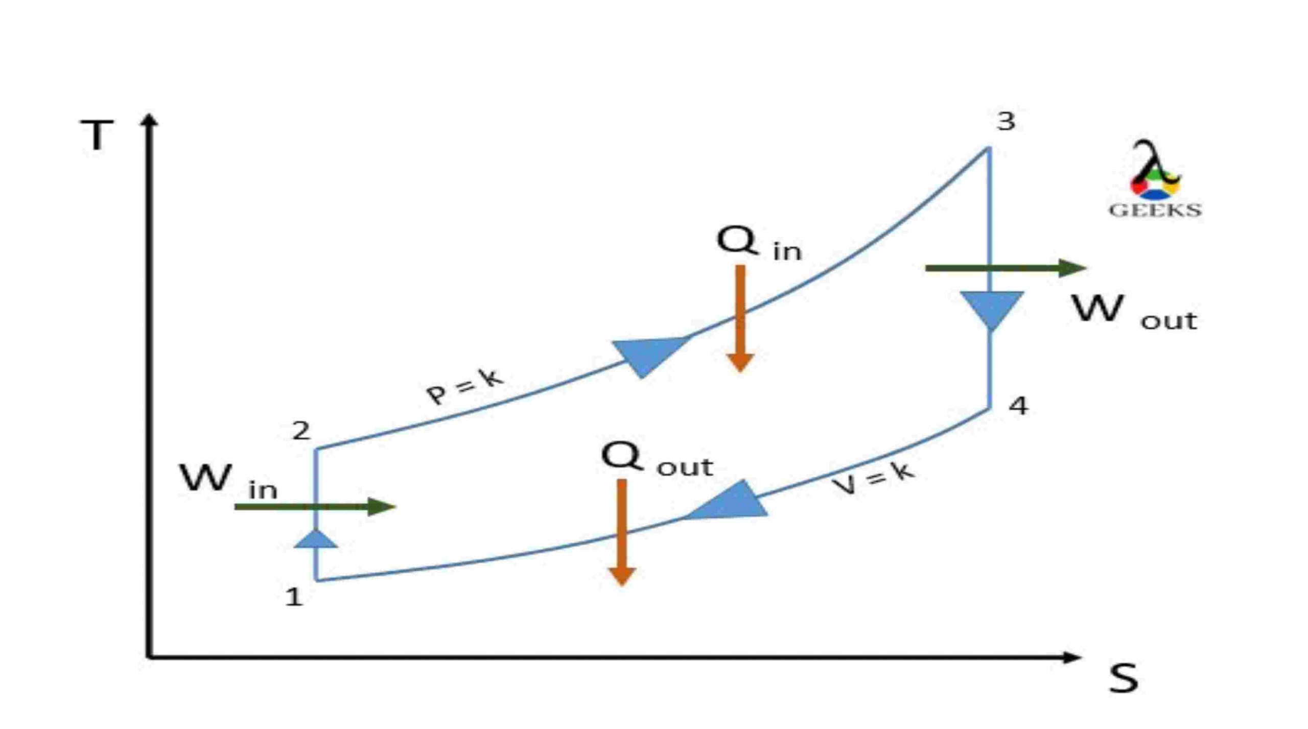
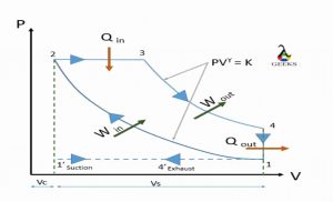
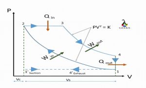
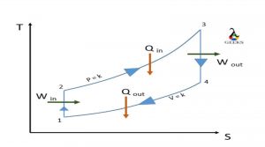
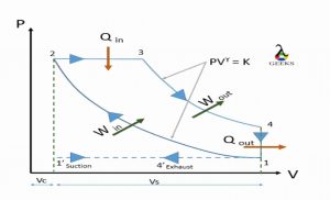
Diesel cycle pv diagram | diesel cycle ts | diesel cycle pv and ts diagram | diesel cycle pv ts diagram | diesel cycle diagram

Diesel cycle
PV daigram
TS daigram
TS daigram

Processes:

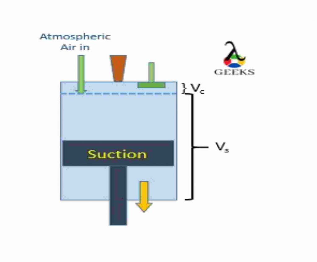
1’- 1: suction of Atmospheric air

Atmospheric air is sucked into the cylinder to carry out the compression process. when piston travel in downward direction towards Bottom Dead Center.

system acts as open system.

1-2: Isentropic Adiabatic compression

The piston travels from Bottom of the cylinder (BDC) to Top of the cylinder (TDC), compressing the air adiabatically, keeping entropy constant. No heat heat interaction is taken under consideration. System acts as a closed system.

2-3: Constant pressure heat addition

just before end of compression stroke, fuel is injected with the help of a fuel manifold, and this mixture of fuel with high temperature and high-pressure air makes the fuel to self-ignite (Unlike the petrol engine, Diesel engine doesn’t have spark plug to help combustion process, it has fuel injector is placed to insert the fuel) and releasing the heat in high amount, causing the force at the head of the piston making it move to BDC. This process is carried out under constant pressure. (Actual process is not possible under constant pressure). At a point it acts as a open system as fuel enters the system.

3-4: Isentropic Adiabatic expansion

The piston travels from Top of the cylinder (TDC) to Bottom of the cylinder (BDC) due to the force result of the combustion. And expansion takes place at constant entropy. No heat interaction is taken under consideration.

system acts as a closed system.

4-1-4’: Exhaust of burnt gases

The burnt gas is let out from the exhaust port to make a start for the next cycle. system again acts a open system. we assume the exhaustion process take place at constant volume.

Diesel cycle analysis

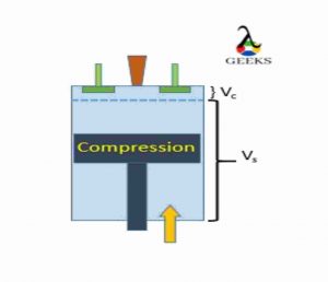
1. The piston in the reciprocating engine moves from Top Dead Center to Bottom Dead Center, causing low pressure inside the cylinder. At this point, the inlet port is let open allowing fresh atmospheric oxygen-rich air to enter into the cylinder. The reciprocating system acts as the open system while this process, allowing mass to enter the system.

this process is carried out at a constant pressure (1′-1)

At the end of the suction, the port is closed, and the the system acts as a closed system.

1 1

2. The ideal cycle process start when the piston reaches the Bottom Dead Center and starts moving towards Top dead Center.

The reciprocating engine plays as a closed-system. The air inside the cylinder is compressed by the piston. the compression is isentropic-adiabatic compression. (No entropy generation and no heat consideration). As a result of compression, the air reaches high pressure and high temperature.

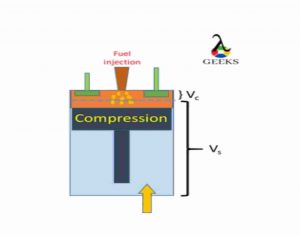
Before the piston reaches the Top of the cylinder (TDC), the fuel is through the manifold in to the cylinder.

This introduced fuel is in spray form; as the fuel comes in contact with the high pressure and high-temperature environment, it gets self-ignited (No need of spark-plug), causing energy release (Chemical energy is transformed into heat energy).

2.1 1
2.2 2

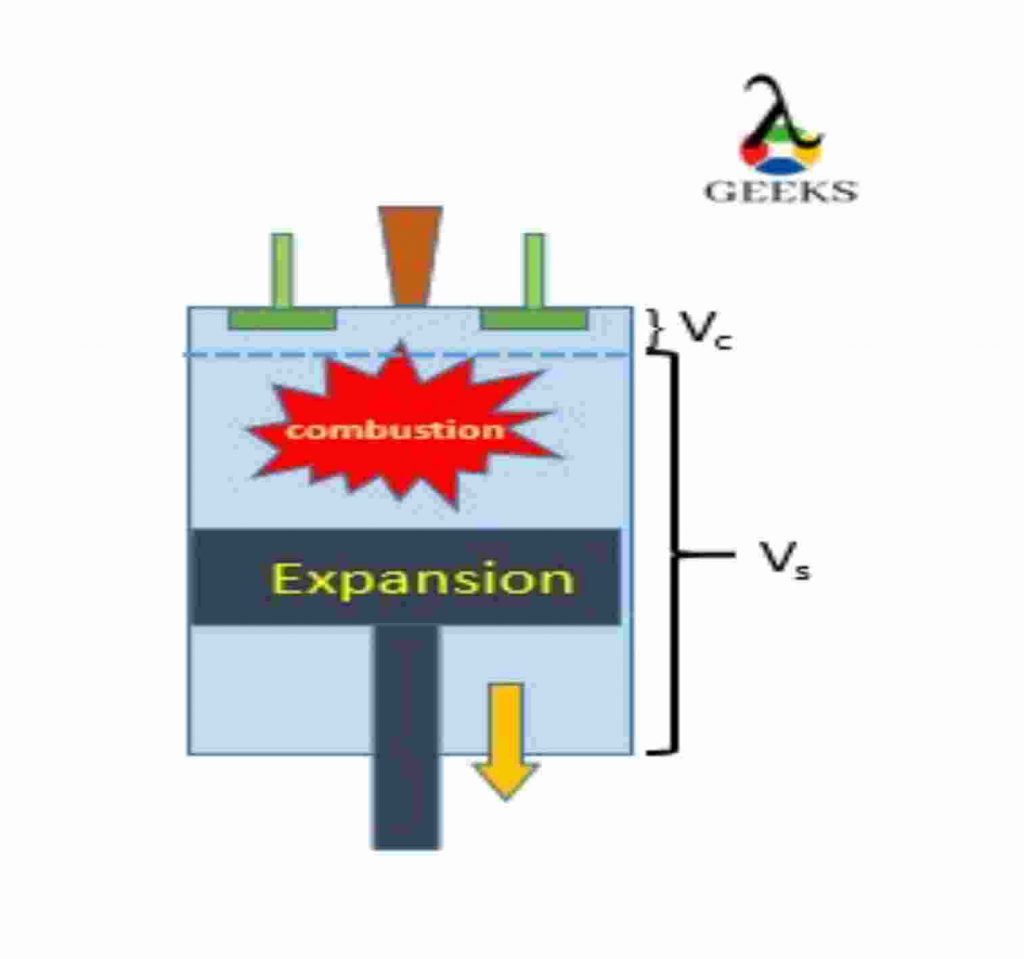
3. The actual power generation takes place at this process; the high force is generated when the combustion takes place, and it forces the piston from Top Dead Center to Bottom Dead Center. The expansion process takes place at this point.

The force is transmitted to run the crankshaft and generate the mechanical energy from the heat energy.

(This stroke is also known as power stroke, in four stroke engine we get one power stroke for every two rotation while in Two stroke we get power power stroke for each rotation.)

3

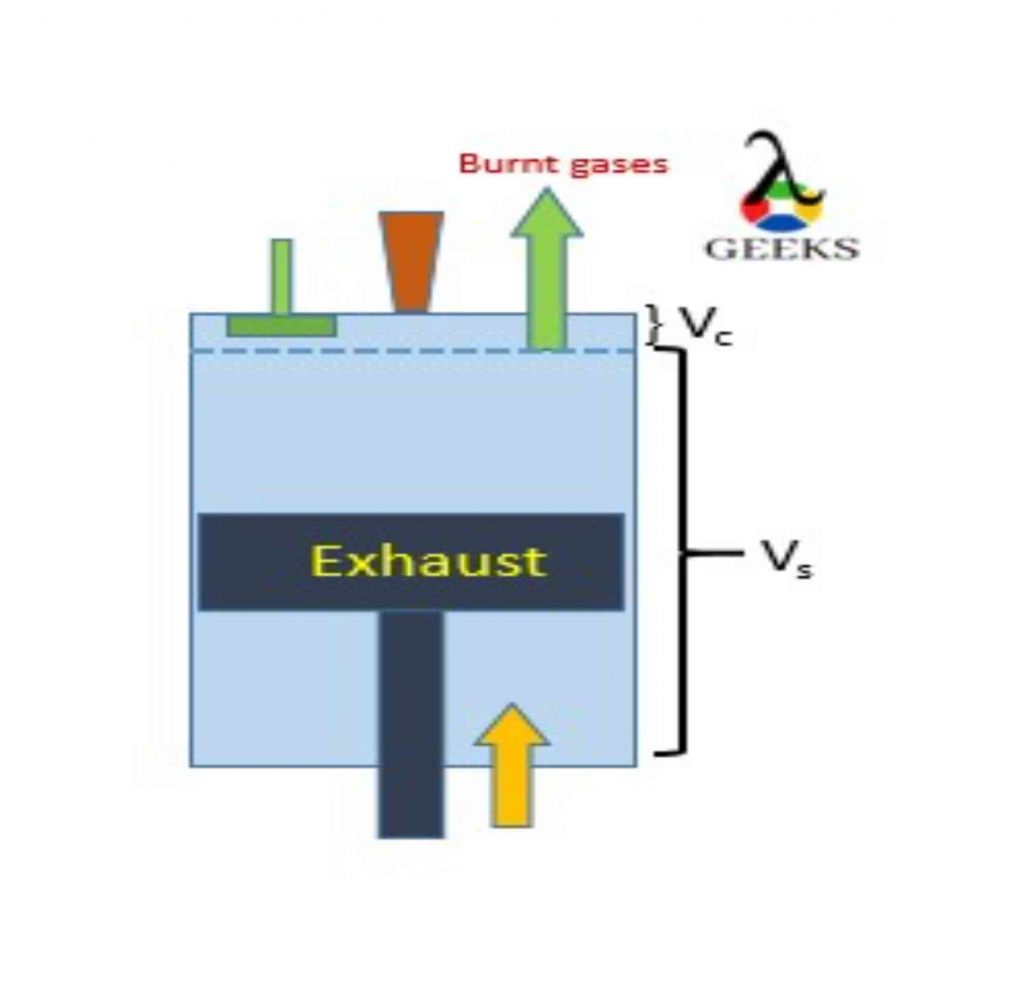
4. Burnt gas (residue) must be let out of the cylinder, hence that work is done by piston by
moving from BDC to TDC

And the one cycle of is completed.

(If reciprocating engine is four stroke each operation take place separately, while for two stoke two operations are performed simultaneously. )

4

Diesel cycle derivation| diesel cycle formula

Heat Rejected:

heat\\ rejected.\\ Q_{2}=\\ Q_{4-1} =\\ m\\ Cv\\ (T_4-T_1)

Work output:

W_{net}=Q_{net}= Q_1-Q_2

W_{net}= Q_{2-3} -Q_{4-1}

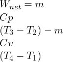
W_{net}=m\\ Cp\\ (T_3-T_2)-m\\ Cv\\ (T_4-T_1)

Compression ratio

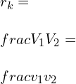
r_{k}=\\ \\frac{V_1}{V_2}=\\ \\frac{v_1}{v_2}

Expansion Ratio

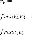
r_{e}=\\ \\frac{V_4}{V_3}=\\ \\frac{v_4}{v_3}

Cut-off ratio:

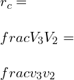
r_{c}=\\ \\frac{V_3}{V_2}=\\ \\frac{v_3}{v_2}

we can corelate the above equation in form as below:

Compression ration can be define as product of expansion ration and cut-off ratio.

r_{k}=\\ r_e\\times r_c

Let us see derivation of each individual process:

Process 3-4:

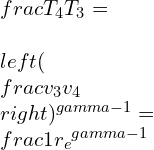
\\frac{T_4}{T_3}=\\ \\left ( \\frac{v_3}{v_4} \\right )^{\\gamma -1}=\\frac{1}{{r_e}^{\\gamma -1}}

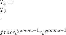
T_4=\\ T_3\\ .\\ \\frac{{r_c}^{\\gamma -1}}{{r_k}^{\\gamma -1}}

Process 2-3:

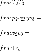
\\frac{T_2}{T_3} =\\ \\frac{p_2 v_2}{p_3v_{3}}=\\ \\frac{v_2}{v_3}=\\ \\frac{1}{r_c}

T_2=\\ T_3\\ .\\ \\frac{1}{r_c}

Process 1-2:

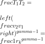
\\frac{T_1}{T_2}=\\ \\left ( \\frac{v_2}{v_1} \\right )^{\\gamma -1}=\\frac{1}{{r_k}^{\\gamma -1}}

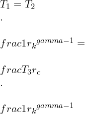
T_1=T_2\\ .\\ \\frac{1}{{r_k}^{\\gamma -1}}=\\ \\frac{T_3}{r_c}\\ .\\ \\frac{1}{{r_k}^{\\gamma -1}}

we will further use this temperature values to get efficiency equation.

The efficiency of diesel cycle derivation | diesel cycle efficiency | diesel cycle efficiency derivation | air standard efficiency of diesel cycle | diesel cycle efficiency formula | derivation of diesel cycle efficiency | thermal efficiency of diesel cycle

Efficiency

Efficiency=\\ \\frac{Work\\ output}{Work\\ input}

\\eta =\\ \\frac{W_{net}}{Q_{in}}

\\eta =\\ \\frac{Q_1-Q_2}{Q_{1}}

\\eta =\\1- \\frac{Q_2}{Q_{1}}

\\eta =\\1- \\frac{m\\ Cv\\ (T_4-T_1))}{m\\ Cp\\ (T_3-T_2)}

\\eta =\\1- \\frac{T_4-T_1}{\\gamma \\ (T_3-T_2)}

By substituting  T1,T2,T3 in eff enq

\\eta =\\ 1\\ -\\ \\frac{T_3.\\frac{{r_c}^{\\gamma -1}}{{r_k}^{\\gamma -1}}.\\frac{T_3}{r_c}\\frac{1}{{r_k}^{\\gamma -1}}}{\\gamma \\left ( T_3-T_3\\ . \\frac{1}{r_c}\\right )}

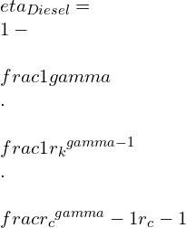
\\eta _{Diesel}=\\ 1-\\ \\frac{1}{\\gamma }\\ .\\ \\frac{1}{{r_k}^{\\gamma -1}}\\ .\\ \\frac{{r_c}^{\\gamma }-1}{{r_c}-1}

Compression ratio of diesel cycle

The compression ratio of the diesel cycle is the ratio of the maximum volume available in the cylinder when the piston is at Bottom Dead Center-(BDC) to the minimum volume available when the piston is at TDC.

Compression\\ ratio= \\frac{Total\\ volume}{clearance\\ volume}

r_{k}=\\ \\frac{V_1}{V_2}=\\ \\frac{v_1}{v_2}

Mean effective pressure formula for diesel cycle

Mean effective pressure is the ratio of network-done to the swept-volume

MEP = \\frac{net work-output}{Swept\\ volume}

MEP = \\frac{m\\ Cp\\ (T_3-T_2)-m\\ Cv\\ (T_4-T_1)}{v_1-v_2}

Cut off ratio in diesel cycle

The cut-off ratio in the diesel cycle is defined as the ratio of volume after combustion to the volume before combustion.

Cut-off\\ ratio= \\frac{Compression\\ ratio}{Expansion\\ ratio}

r_{c}=\\ \\frac{V_3}{V_2}=\\ \\frac{v_3}{v_2}

Semi diesel cycle

Semi diesel cycle, also known as the dual cycle, is the combination of otto and diesel cycles.

In this semi diesel/ dual cycle the heat is added at both constant volume and constants pressure.

( there is simple modification only, the part of heat added is under the constant volume and a remaining part of heat is added at constant pressure)

dual pv 2
P-V diagram

process:

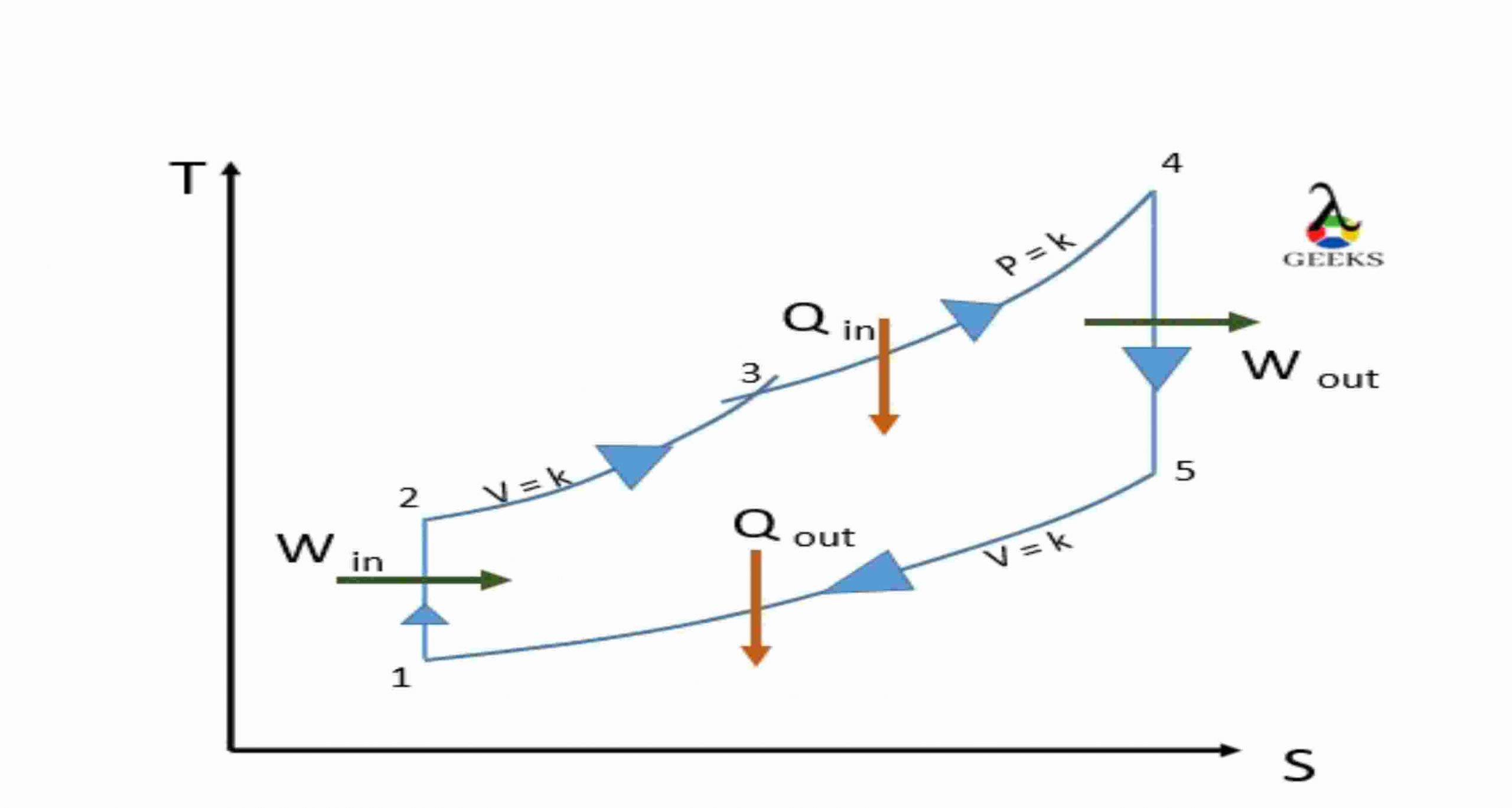
Dual Ts 2
T-S diagram

1-2: Isentropic Adiabatic compression:

Air is compressed adiabatically, keep entropy constant and no heat interaction.

2-3: Constant volume Heat addition:

just before the end of compression stroke , that is piston reaches the TDC of cylinder, the fuel is
added and combustion take place at a Isochoric condition, (constant volume).

3-4: Constant pressure Heat addition

A part of combustion is also carried at at constant pressure. and with this heat addition is completed.

4-5: Isentropic Adiabatic expansion

Now, as the high amount of force is generated it pushes piston now and causes the power stroke.

The work output is obtain at this point.

5-6: Constant volume Heat rejection

At the end the burnt gas is let out of the system to make place for fresh supply of air and carry out next cycle.

Two cycle diesel

A two-cycle diesel engine, also known as a two-stroke diesel engine, works similarly to a four-stroke diesel engine. But it gives power stroke for each revolution while a four-stroke engine gives power stroke for two revolutions.

There exists a transfer port inside the cylinder to carry two operations simultaneously.

When the compression takes place, the suction is also taking place.

And when expansion takes place, the input of oxygen-rich air takes place, letting exhaust burn gas out

Simultaneously.

Difference between diesel and otto cycle| diesel vs otto cycle

ParametersDiesel cycleOtto cycle
DefineThe diesel cycle or Ideal diesel cycle is the power-producing cycle where heat addition takes place at constant pressure.The Otto cycle is also the ideal power-generating cycle, where heat addition takes place at Isochoric condition (constant volume.)
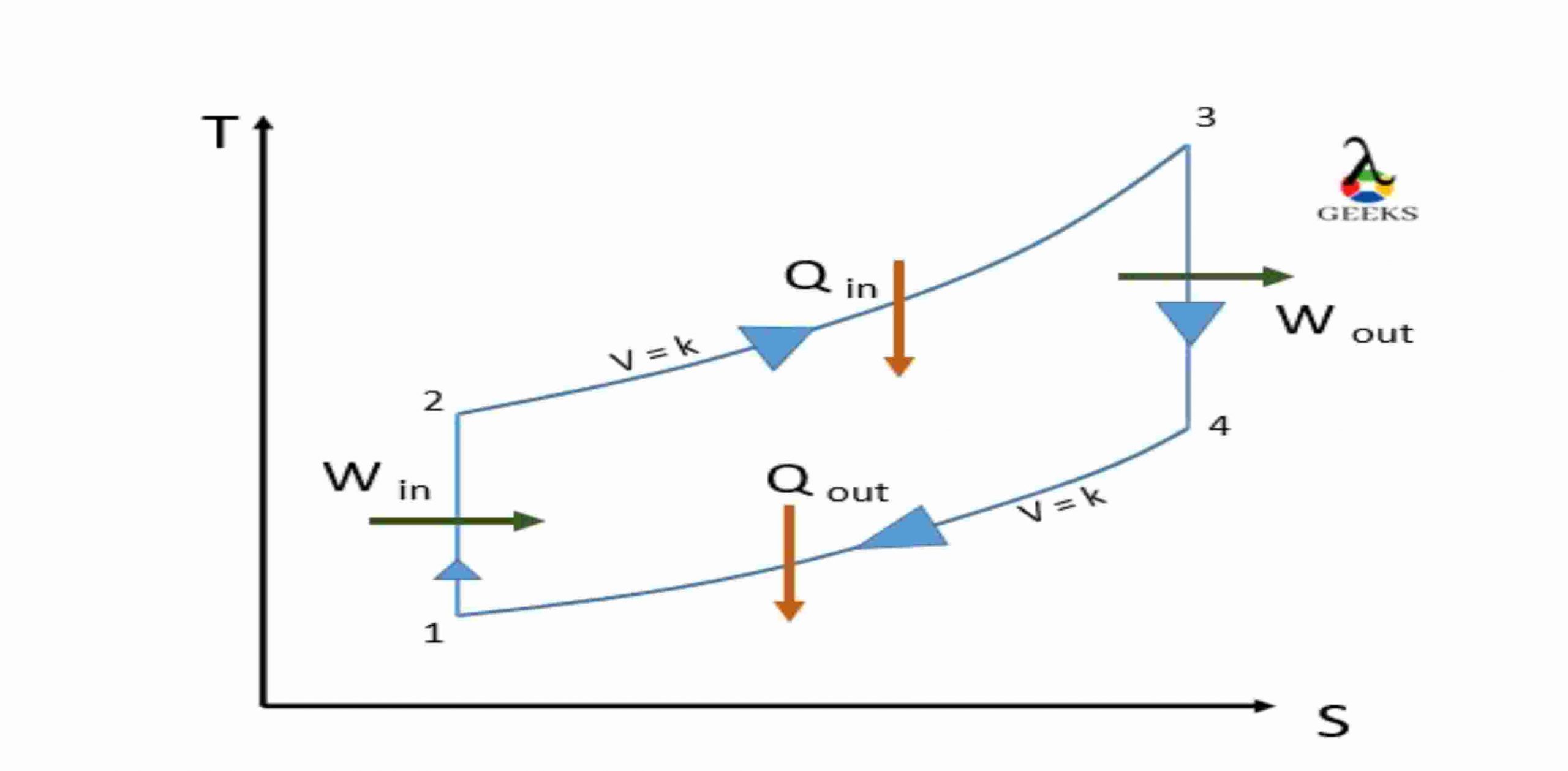
T-S diagramTS 1 scaledotto scaled
ProcessTwo isentropic ( 1-2 & 3-4 )
One isobaric heat addition (2-3)
One isochoric heat rejection (4-1)
Two isentropic ( 1-2 & 3-4 )
one isochoric heat addition (2-3)
one isochoric heat rejection (4-1)
Compression ratioThe efficiency of diesel cycle is more as compare to Otto cycle..The efficiency of diesel cycle is less as compare to Otto cycle.
Same compression ratioThe efficiency of diesel cycle is less as compare to Otto cycle.The efficiency of diesel cycle is more as compare to Otto cycle.
Same maximum pressureThe efficiency of diesel cycle is less as compare to Otto cycle.The efficiency of diesel cycle is more as compare to Otto cycle.
ApplicationDiesel cycle is used for Diesel/IC engineOtto cycle is used for Petrol/SI engine

difference between otto cycle diesel cycle and dual cycle

ParametersDiesel cycleOtto cycleDual Cycle
DefineThe diesel cycle or Ideal diesel cycle is the power-producing cycle where heat addition takes place at constant pressure.The Otto cycle is also the ideal power-generating cycle, where heat addition takes place at Isochoric condition (constant volume.)The dual cycle or semi diesel cycle is a combination of the Otto and diesel cycles. In this cycle, the heat is added at both Isochoric condition (constant volume) and isobaric condition (constants pressure.)
T-S diagramTS 1 scaledotto scaledDual Ts scaled
ProcessTwo isentropic (1-2&3-4 )
One isobaric heat addition (2-3)
One isochoric heat rejection (4-1)
Two isentropic (1-2 & 3-4 ) one isochoric heat addition (2-3)
one isochoric heat rejection ( 4-1)
Two isentropic ( 1-2 & 4-5 )
One isochoric heat addition(2-3)
One isobaric heat addition (3-4)
One isochoric heat rejection (4-1)
Compression ratioCompression ratio is 15-20Compression ratio is 8-10Compression ratio is 14
Same compression ratioThe Efficiency of diesel cycle is more as compare to The Otto cycle.The Efficiency of diesel cycle is less as compare to The Otto cycle.The efficiency is between
both the cycles (i.e Otto and
Diesel)
Same maximum pressureThe Efficiency of diesel cycle is less as compare to The Otto cycle.The Efficiency of diesel cycle is more as compare to The Otto cycle.The efficiency is between
both the cycles (i.e Otto and
Diesel)
ApplicationDiesel cycle is used for Diesel/IC engineOtto cycle is used for Petrol/SI engineDual cycle is used for IC engine.

Application of diesel cycle

Diesel-Internal Combustion engines:

  • Automobiles Engines
  • Ships and marine applications
  • Transport vehicles.
  • machinery used for agriculture
  • construction equipment and machines
  • military and defense
  • HVAC
  • Power generation

Advantages of diesel engine

New advanced have made diesel engine performance quite good, it is less noisy and has low maintenance cost.

Diesel engine are reliable and robust.

No need of spark-plug , fuel used is of self-igniting nature.

fuel cost is also low as compare to petrol.

diesel cycle sample problems | diesel cycle example | diesel cycle example problems

Q1.With compression ratio of 14, and cut-off at 6% what will be the efficiency of the diesel cycle?

Ans=

Pv 3

r_k=\\frac{v_1}{v_2}=14

v_3-v_2=0.06(v_1-v_2)

v_3-v_2=0.06(14v_2-v_2)

v_3-v_2=0.78v_2

v_3=1.78v_2

Cut-off ratio, r_c=\\frac{v_3}{v_2}=1.78

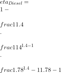
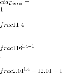
\\eta _{Diesel}=\\ 1-\\ \\frac{1}{\\gamma }\\ .\\ \\frac{1}{{r_k}^{\\gamma -1}}\\ .\\ \\frac{{r_c}^{\\gamma }-1}{{r_c}-1}

\\eta _{Diesel}=\\ 1-\\ \\frac{1}{1.4}\\ .\\ \\frac{1}{{14}^{\\1.4 -1}}\\ .\\ \\frac{{1.78}^{1.4 }-1}{{1.78}-1}

\\eta _{Diesel}=\\ 1-0.248.\\frac{1.24}{0.78}=0.605

\\eta _{Diesel}=60.5%

Q2. Standard diesel cycle with compression ratio of 16, Heat is added at constant pressure of 0.1 MPa. Compression begins at 15 deg Celsius and reaches 1480 deg Celsius at end of combustion.

Find the following:

1. Cut-off ratio

2. Heat added/kg of air

3. Efficiency

4. MEP

Ans=

r_k=\\frac{v_1}{v_2}=16

T1= 273 + 15 = 288K


p1= 0.1 MPa = 100 KN/m2


T3 = 1480 + 273 = 1735K

Pv 4
TS 2

\\frac{T_2}{T_1}= \\left ( \\frac{v_1}{v_2} \\right )^{\\gamma -1}=(16)^{0.4}=3.03

T_2= 288 \\times 3.03= 873K

\\frac{p_2v_2}{T_2}=\\frac{p_3v_3}{T_3}

(a) Cut-off ratio:
r_c=\\frac{v_3}{v_2}=\\frac{T_3}{T_2}=\\frac{1753}{273}=2.01

(b) Heat Supplied:
Q_1=Cp\\ (T_3-T_2)

Q_1=1.005\\ (1753-873)

Q_1=884.4 kJ/kg

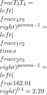
\\frac{T_3}{T_4}=\\left ( \\frac{v_4}{v_3} \\right )^{\\gamma -1}=\\left ( \\frac{v_1}{v_2}\\times \\frac{v_2}{v_3} \\right )^{\\gamma -1}=\\left ( \\frac{16}{2.01} \\right )^{0.4}=2.29

T_4=\\frac{1753}{2.29}=766\\ K

heat rjected,

Q_2=Cv\\ (T_4-T_1)

Q_2=0.718\\ (766-288)=343.2kJ/kg

(c) Cycle Efficiency = 1-\\frac{Q_2}{Q_1}

\\eta =1-\\frac{343.2}{884.4}=0.612=61.2%

Also can be determined by;

\\eta _{Diesel}=\\ 1-\\ \\frac{1}{\\gamma }\\ .\\ \\frac{1}{{r_k}^{\\gamma -1}}\\ .\\ \\frac{{r_c}^{\\gamma }-1}{{r_c}-1}

\\eta _{Diesel}=\\ 1-\\ \\frac{1}{1.4}\\ .\\ \\frac{1}{{16}^{1.4 -1}}\\ .\\ \\frac{{2.01}^{1.4 }-1}{{2.01}-1}

\\eta _{Diesel}=1-\\frac{1}{1.4}.\\frac{1}{3.03}.1.64

\\eta _{Diesel}=0.612= 61.2%

W_{net}=Q_1\\times \\eta _{cycle}

W_{net}=884.4\\times 0.612\\times = 541.3 kJ/kg

v_1=\\frac{RT_1}{p_1}=\\frac{0.287\\times 288}{100}=0.827m^{3}/kg

v_2=\\frac{0.827}{16}=0.052\\ m^3/kg

\\therefore\\ v_1-v_2=0.827-0.052=0.775\\ m^3/kg

(d) mean effective pressure (MEP):

MEP=\\frac{W_{net}}{v_1-v_2}=\\frac{541.3}{0.775}=698.45 kPa

FAQs

Otto cycle vs. diesel cycle efficiency

At the same compression ratio: efficiency of diesel cycle is more as compare to Otto cycle.
At same maximum pressure: efficiency of diesel cycle is less more as compare to Otto cycle.

Diesel cycle chart

1’- 1: suction of Atmospheric air

1-2: Adiabatic compression

2-3: Constant pressure heat addition (fuel injection & combustion)

3-4: Adiabatic expansion

4-1-4’: Exhaust of burnt gases

Pv 2

When the efficiency of diesel cycle approaches the Otto cycle efficiency

The efficiency of the diesel cycle approaches the Otto cycle efficiency when the cut-off ratio approaches zero.

Why are engines that use the Diesel cycle able to produce more torque than engines using the Otto cycle

The diesel engine has a greater compression ratio than the Otto cycle engine.

Combustion in the diesel cycle takes place at TDC at the end of the compression stroke and causes the piston to move downward. While in the Otto cycle, engine combustion takes place when the piston is slightly moving towards BDC and contributes to acquire speed.

Diesel fuel is more dense than petrol (used in the Otto cycle), which generates more energy in terms of power.

Also, the size factor does matter; the stroke length and Bore diameter of the Diesel engine is greater than the Otto cycle engine.

Why cant petrol be used in a diesel cycle.

The volatility of petrol is much higher than Diesel; even before completion of the compression stroke, the high pressure will evaporate the fuel.

Hence petrol will ignite in the uncontrolled matter, causing detonation and misfiring.

it will result in damaging of the cylinder hence one should never start the engine if such incidence take place. It is advisable to contact the concern person to remove the petrol form the engine.

Why is the diesel cycle only applicable to large low-speed engines

Diesel cycle uses fuel which is more viscous and power produce in terms of the torques is more.

when we need application of high load we cant use petrol engine as the efficiency will be less for loading condition and will use more fuel.

hence the diesel engine will be beneficial here where the power produce is more at low speed.

for more article related to Mechanical Engineering visit our website.

Overall Heat Transfer Coefficient: 11 Important Facts

Capture 300x161 1

WHAT IS THE OVERALL HEAT TRANSFER COEFFICIENT?

In industry, heat transfer problems are usually resolved for composite materials or systems with different layers which involve different modes of heat transfer such as conduction, convection, and radiation. The thermal resistance that is offered by the different layers in a system is referred to as the Overall Heat Transfer Coefficient. It is also known as the U-factor.

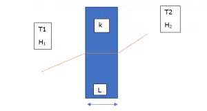
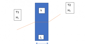
The U-factor that is used in calculating overall heat transfer is analogous to the convection heat transfer coefficient used in Newton’s law of cooling. The overall heat transfer coefficient is dependant on the geometry of the object or surface. For example, in a wall, we can observe different modes of heat transfer, the outer surface of the wall experiences convection heat transfer while the space between the walls undergoes conduction mode of heat transfer.

The overall heat transfer coefficient of the wall is taken to be a sum of the convective heat transfer coefficient and the conductive heat transfer coefficient. In short, the overall heat transfer coefficient is the summation of the individual heat transfer coefficient. Further explanation on the derivation of the overall heat transfer coefficient and using it for composite heat transfer problems are explained below.

SIGNIFICANCE OF OVERALL HEAT TRANSFER COEFFICIENT

In industrial applications, it is essential to know the overall heat transfer coefficient, especially in cases where the heat transfer rate needs to be optimized for better performance of a system. To calculate the heat transfer rate Q(dot) for any system with different fluids or different layers, it is essential to know the overall heat transfer coefficient.

From the value of the overall heat transfer coefficient and the rate of heat transfer, it is possible to calculate the individual heat transfer coefficient. This would help in modifying a particular portion of the thermal system for better performance as per the requirements.

Under steady-state conditions, the rate of heat transfer from a fluid at bulk temperature T1 to solid at bulk temperature T2 over an incremental area dA  is given by the rate of heat transfer dQ(dot) i.e.

dQ(dot) = U*(T2 – T1)*A

Here the overall heat transfer coefficient is represented by the letter U.

FORMULA FOR OVERALL HEAT TRANSFER COEFFICIENT | HOW TO FIND OVERALL HEAT TRANSFER COEFFICIENT | OVERALL HEAT TRANSFER COEFFICIENT FORMULA | HOW TO CALCULATE OVERALL HEAT TRANSFER COEFFICIENT | OVERALL HEAT TRANSFER COEFFICIENT DERIVATION

The formula for the Overall Heat Transfer coefficient is given by

Qdot = U*(T1 + T2)*A

Derivation for the Overall Heat Transfer coefficient for Wall given below

Overall Heat Transfer coeffiicient

Consider a composite wall that is exposed to the external environment at temperature T1, and the conduction coefficient is noted to be H1. The ambient temperature inside the room is T2 and the convection coefficient is H2. Here the heat transfer is using conduction and convection. Either side of the wall experiences heat transfer using convection at different magnitudes.

The temperature inside the wall varies and is a value between T1 and T2 if there is no source of heat generation from within the wall. The conduction coefficient of the wall is taken to be K in this case unless the wall is made up of different layers which is the usual case. In real life scenario, the wall is made up of different layers such as plastering, bricks, cement, etc. In such cases, it is essential to take into consideration the thermal resistance offered by each layer of the wall.

The overall heat transfer coefficient for the above system is as given below:

1

And the rate of heat transfer Q(dot) = UAΔT

It is evident that U is not a thermophysical property and depends on the flow, velocity, and also on the material through which the heat transfer takes place.

OVERALL HEAT TRANSFER COEFFICIENT WITH FOULING

Fouling is a usual problem that is encountered in heat exchangers. It is an additional layer that is formed on the inner surface of the heat exchanger. Several factors contribute to the fouling of the surfaces of heat exchangers. The rate of heat transfer is reduced because of fouling which in turn affects the heat transfer efficiency.

The decrease in heat transfer efficiency is accounted for in calculations using the fouling factor. It is often referred to as the dirt factor. The fouling factor is dependent on the fluid on either side of the heat exchanger.

The overall heat transfer coefficient with fouling is given by

he fouling

In the above equation,

U represents the overall heat transfer coefficient

h0 is the heat transfer coefficient on the shell side

hi is the heat transfer coefficient on the tube side

Rdo is the fouling factor on the shell side

Rdi is the fouling factor on the tube side

OD is the outer diameter of the tube

ID is the inner diameter of the tube

A0 is the outer area of the tube

Ai is the inner area of the tube

Kw is the value of resistance offered by the tube wall

From the equation, it is evident that the value of the overall heat transfer coefficient decreases with an increase in either or both values of fouling factor (i.e., tube side or shell side). This decrease in the overall heat transfer coefficient will in turn reduce the rate of heat transfer.

OVERALL HEAT TRANSFER COEFFICIENT UNITS | OVERALL HEAT TRANSFER COEFFICIENT UNIT CONVERSION | OVERALL HEAT TRANSFER COEFFICIENT CONVERSION

The S.I. unit of overall heat transfer coefficient is W/m2 K. Another unit that is used for representing the overall heat transfer coefficient is Btu/(hr.ft2 0F).

The unit conversion from SI unit to English units is follows:

1 W/m2 K = = 0.1761 Btu/(hr.ft2 0F).)

EFFECT OF FLOW RATE ON OVERALL HEAT TRANSFER COEFFICIENT | OVERALL HEAT TRANSFER COEFFICIENT VS FLOW RATE

The flow rate has an impact on the overall heat transfer coefficient. It is noted that there is a 10% decrease in heat transfer coefficient when the mass flow rate increases by three times. This estimation of the heat transfer coefficient is based on the Dittus-Boelter correlation.

While keeping the area constant, it is observed that the heat transfer coefficient increases by increasing the mass flow rate. A 90% increase in heat transfer coefficient is expected by doubling the mass flow rate. With this increase, there is an expected increase of pressure drop which is proportional to the mass flow rate.

For cases where the velocity is constant, the pressure drop decreases and is inversely proportional to the mass flow rate. The positive aspects that are attained from a higher heat transfer coefficient are lost due to the increased pressure drop when the area is kept constant.

OVERALL COEFFICIENT OF HEAT TRANSFER TABLE

The table below provides the overall heat transfer coefficient for a few equipment that are very often used in the industry. The range is provided because the overall heat transfer coefficient is dependent on the fluid that is used in the equipment. For gases, the value of the heat transfer coefficient is very low and that of liquids is much higher.

EquipmentU (W/m2)
Heat Exchanger5-1500
Coolers5-1200
Heaters20-4000
Condensers200-1500
Air Cooled Heat Exchangers50-600
Table 1: Overall Coefficient of Heat Transfer for different Equipment

AVERAGE OVERALL HEAT TRANSFER COEFFICIENT

In heat transfer problems which consist of two different fluids which could be water and alcohol at two different temperatures, in such cases the average of the temperatures of the two fluids is used for solving the heat transfer problem which is termed as the average overall heat transfer coefficient.

Let’s take Q to be the heat flowing through the surface at an average temperature ΔTavg, and the area across which the heat transfer takes place is taken to be A. The average overall heat transfer coefficient for this heat flow is as given below

2

OVERALL HEAT TRANSFER COEFFICIENT BASED ON INSIDE AREA

For heat exchangers, the overall heat transfer coefficient can be based on either the inside area or on the outside area

When the overall heat transfer coefficient is calculated based on the inside area, the convection coefficient at the inside is taken to be 1/hi, while the conduction coefficient at the interface is taken to be 1/ln(r0/ri)/2πkL and the convection coefficient on the outer surface of the heat exchanger is taken to be 1/h0.

Therefore, the overall heat transfer coefficient based on the inside area is given as

in 1

When the overall heat transfer coefficient is calculated based on the outside area, the convection coefficient at the inside is taken to be 1/hi, while the conduction coefficient at the interface is taken to be 1/ln(r0/ri)/2πkL and the convection coefficient on the outer surface of the heat exchanger is taken to be 1/h0.

Therefore, the overall heat transfer coefficient based on the inside area is given as

out 1

The significant difference between the two-equation is in the area, when the overall heat transfer coefficient is based on the inside area, the inner area of the heat exchanger is used in the equation. While when the overall heat transfer coefficient is based on the outside area, the outer area is taken in the equation.

DIFFERENCE BETWEEN INDIVIDUAL AND OVERALL HEAT TRANSFER COEFFICIENT

When heat is flowing through a composite material, the thermal resistance offered by different layers of the material which can be due to heat conduction or convection is referred to as the overall heat transfer coefficient. The overall heat transfer coefficient is the summation of the individual heat transfer coefficient. The thermal resistance is analogous to the electrical resistance in a circuit. Here the heat transfer coefficient is dependent on the material in series or parallel arrangement.

It is of great interest to determine the individual heat transfer coefficient from the overall heat transfer coefficient. For example, for a heat exchanger, the overall heat transfer coefficient can be measured experimentally, from this overall coefficient, extracting the thermal resistance offered by the hot and cold fluid individually is the problem to be solved.

OVERALL HEAT TRANSFER COEFFICIENT PROBLEMS

Consider a wall of thickness 5cm is made of bricks which has a thermal conductivity K=20 W/m K. The inner surface of the wall is exposed to room temperature of 250C while the external surface is exposed to the hot atmospheric temperature of 400C. What is the overall heat transfer coefficient, given the convection coefficient of air 25 W/m2K?

From the above problem, we can conclude that the system is exposed to convection on either side of the wall and conduction heat transfer within the wall. The thermal conductivity of the wall is given to be 20W/mK while the convection coefficient of air is noted to be 25 W/m2K.

calc

= 12.12 W/m2K

FREQUENTLY ASKED INTERVIEW QUESTIONS AND ANSWERS

1. overall heat transfer coefficient equation heat exchanger

he fouling 2

2. overall heat transfer coefficient double pipe | double pipe heat exchanger overall heat transfer coefficient

1/U = Do/hi.Di + Do.ln(Do/Di)/2kt + 1/ho+ Ri.Do/Di + Ro

3. overall heat transfer coefficient formula for cylinder

The overall heat transfer coefficient for a cylinder is given by the formula below which experiences both conduction and convection mode of heat transfer

cylinder

4. overall heat transfer coefficient for evaporator

TypeU (W/m2K)
Natural circulation – steam flowing outside and highly viscous fluid flowing inside300-900
Natural circulation – steam flowing outside and low viscous fluid flowing inside600-1700
Forced circulation – steam flowing outside and liquid flowing inside900-3000
Table 2: Overall Heat Transfer Coefficient for Evaporators

5. Overall heat transfer coefficient shell and tube | overall heat transfer coefficient for shell and tube heat exchanger | how to calculate overall heat transfer coefficient for heat exchanger | How do you calculate the overall heat transfer coefficient of an evaporator?

The overall heat transfer coefficient for any heat exchanger can be calculated using the below equation the method used might vary. One can choose the LMTD method as well

he fouling 1

6. Graphite heat exchanger overall heat transfer coefficient

The overall heat transfer coefficient for heat exchangers which are molded graphite to graphite is about 1000W/m2K while the overall heat transfer coefficient for graphite to air is observed to be 12 W/m2K

7. Aluminium overall heat transfer coefficient

The overall heat transfer coefficient for aluminum is noted to be 200W/m2K

8. Air to air heat exchanger overall heat transfer coefficient

The overall heat transfer coefficient of air-to-air heat transfer coefficient is noted to be between 350 to 500 W/m2K.

9. Area of the heat exchanger from overall heat transfer coefficient

The area of a heat exchanger can be calculated from the overall heat transfer coefficient using the following formula

he area

10. In which heat exchange process the value of the overall heat transfer coefficient will be highest?

The overall heat transfer coefficient is the highest for tubular heat exchangers used for evaporation with steam flowing outside the tubes and liquid flowing inside. They are noted to have an overall heat transfer coefficient in the range between 900 to 3000 W/m2K.

11. Can the overall heat transfer coefficient be negative?

In cases where the reference temperature is taken as the adiabatic wall temperature, the overall heat transfer coefficient will be negative which indicates that the heat flux is in the opposite direction with a definite temperature gradient.

12. Does the overall heat transfer coefficient change with temperature?

Overall heat transfer coefficient is dependent on the temperature gradient; therefore, temperature changes can result in changes in a temperature gradient. So, yes overall heat transfer coefficient changes with temperature.

13. What is the overall heat transfer coefficient and its application?

The thermal resistance that is offered by the different layers in a system is referred to as the Overall Heat Transfer Coefficient. It is also known as the U-factor. It is used in extracting the individual heat transfer coefficient of the different layers of a system.

The overall heat transfer coefficient of a system can be measured but the individual heat transfer coefficient of a system is difficult to obtain. In such situations, the overall heat transfer coefficient along with the rate of heat transfer will help in determining the individual heat transfer coefficient

14. What are the factors affecting the overall heat transfer coefficient?

The factors affecting the overall heat transfer coefficient are thermophysical properties such as the density, viscosity, and thermal conductivity of the fluid. Further, it is affected by the geometry and area across which the heat transfer is taking place. The velocity of fluids affects the overall heat transfer coefficient to a large extend. In heat exchanges, the type of flow also has a significant impact on the overall heat transfer coefficient.

15. What is the overall heat transfer coefficient in round tubes? | overall heat transfer coefficient pipe

A fluid flowing through a round tube experiences convective heat transfer between the fluid flowing on the outside and the outer surface of the tube, and also between the fluid flowing in the inside and the inner surface of the tube. There is conduction heat transfer between the outer surface and inner surface of the tube. Hence the overall heat transfer coefficient is given as follow:

(1/UA) overall = (L/kA) inner + (1/hA) + (L/kA) outer

Where k is the thermal conductivity of the tube and h is the convective heat transfer coefficient

Click Here, for latest reads on Thermostatic Expansion Valve.

For more post on Mechanical, please follow us.

Carnot Cycle: 21 Important Facts You Should Know

1 1 300x200 1

CARNOT CYCLE

Nicolas Léonard Sadi-Carnot, a French mechanical engineer, Scientist, and physicist, introduced a heat engine known as the Carnot Engine in the book “Reflections on the Motive Power of Fire. It leads to being the foundation of the Second law of thermodynamics and entropy. Carnot’s contribution holds a remark which gave him the title of “Father of Thermodynamics.

Table of Content

Carnot cycle in thermodynamics | working principle of Carnot cycle | ideal Carnot cycle | Carnot cycle thermodynamics | Carnot cycle definition | Carnot cycle working principle | air standard Carnot cycle| Carnot cycle reversible.

Carnot cycle is the theoretical cycle that works under two thermal reservoirs (Th & Tc) undergoing compression and expansion simultaneously.

It consists of four reversible processes, of which two are isothermal, i.e., constant temperature followed alternately by two reversible adiabatic processes.

The working medium used in the Sadi-Carnot cycle is atmospheric air. 

Heat addition and Heat rejection are carried out at a constant temperature, but no phase change is considered.

Carnot cycle
Carnot cycle

Importance of Carnot Cycle

The invention of the Carnot cycle was a very big step in the history of thermodynamics. First, it gave theoretical working of heat engine used for the design of an actual heat engine. Then, reversing the cycle, we get refrigeration effect (mentioned below). 

Carnot cycle work between two thermal reservoirs (Th & Tc), and its efficiency depends only on this temperature and doesn’t depend on the fluid type. That is Carnot’s cycle efficiency is fluid independent.

Carnot cycle pv diagram | Carnot cycle ts diagram | pv and ts diagram of Carnot cycle | Carnot cycle pv ts | Carnot cycle graph | Carnot cycle pv diagram explained | Carnot cycle ts diagram explained

2 1 2
P-V Carnot
3 3
T-S Carnot

Process 1-2: Isothermal expansion

In this process, the air is expanded with constant temperature while gaining heat. 

That is, constant temperature heat addition takes place. 

Expansion => pressure ↑ => results Temperature ↓

Heat Addition => Temperature ↑

Hence Temperature remain constant 

Process 2-3: Reversible adiabatic expansion 

In this process, the air is expanded, keeping entropy constant and with no heat interaction. 

That is no change in entropy, and the system is insulated

We get work output in this process

Process 3-4: isothermal compression

In this process, the air is compressed with a constant temperature while losing heat.

That is, constant temperature heat rejection takes place.

Compression => pressure ↓ => results: Temperature ↑

Heat Addition => Temperature ↓

Hence Temperature remain constant 

Process 4-1: Reversible Adiabatic Compression

In this process, the air is compressed, keeping entropy constant and no heat interaction. 

That is no change in entropy, and the system is insulated

We supply work in this process

Carnot cycle consists of | Carnot cycle diagram | Carnot cycle steps | 4 stages of Carnot cycle | Carnot cycle work| isothermal expansion in Carnot cycle| Carnot cycle experiment

Process 1-2:

The expansion process is carried out where temperature Th is kept constant, and heat (Qh) is added to the system. The temperature is kept constant as follows: The rise in temperature due to heat addition is compensated by the decrease in temperature due to expansion. 

Hence the process carried out results as constant temperature as the start and end temperature of the process is same.

Isothermal expansion

Process 2-3:

As we can see, the process is reversible (change in internal energy = 0) Adiabatic (only work transfer, no heat involvement), the expansion carried out just results in a change in temperature (from Th to Tc), keeping the entropy constant. 

System act as being insulated for this part of the expansion. 

Sensible cooling is taking place.

Reversible Adiabatic expansion

Process3-4:

The compression process is carried out where temperature Tc is kept constant, and heat is removed from the system. The temperature is kept constant as follows: The decrease in temperature due to heat rejection is compensated by the increase in temperature due to compression. 

Hence the process carried out results as constant temperature as the start and end temperature of the process is same.

Similar to processes 1-2 but in the exact opposite manner.

Isothermal Compression

Process 4-1:

As we can see, the process is reversible (change in internal energy = 0) Adiabatic (only work transfer, no heat involvement), the compression carried out just results in a change in temperature (from Tc to Th), keeping the entropy constant. 

System act as being insulated for this part of the compression. 

Sensible heating is taking place.

6.41
Reversible Adiabatic Compression

Carnot cycle equations| Carnot cycle derivation

Process 1-2: Isothermal expansion

as Th is kept constant. [Internal energy (du) = 0] ( PV = K)

Qh = W ,

therefore, W = int_{V_{1}}^{V_{2}}PdV

P = frac{K}{V}

W = Kint_{V_{1}}^{V_{2}}frac{dV}{V}

W = P_{1}V_{1}int_{V_{1}}^{V_{2}}frac{dV}{V}

W = P_{1}V_{1}left ( lnfrac{V_{2}}{V_{1}} right )

W = mRT_{h}left ( lnfrac{V_{2}}{V_{1}} right )

Process 2-3: Reversible adiabatic expansion

PV^{gamma } = K

W = int_{V_{2}}^{V_{3}}PdV

PV^{gamma } = K

therefore W = Kint_{V_{2}}^{V_{3}}frac{dV}{V^{gamma }}

W = P_{2}V^{gamma }_{2}int_{V_{2}}^{V_{3}}frac{dV}{V^{gamma }}

W = P_{2}V^{gamma }_{2}int_{V_{2}}^{V_{3}}{V^{-gamma }{dV}}

W = Kint_{V_{2}}^{V_{3}}{V^{-gamma }{dV}}

W = K left [ frac{V^{1-gamma }}{1-gamma } right ]_{2}^{3}

PV^{gamma } = K = P_{2}V_{2}^{gamma } = P_{_{3}}V_{3}^{gamma }

W=left [ frac{P_{3}V^{gamma }_{3}V_{3}^{1-gamma }-P_{2}V^{gamma }_{2}V_{2}^{1-gamma }}{1-gamma } right ]

W=left [ frac{P_{3}V_{3}-P_{2}V_{2}}{1-gamma } right ]

Also

P_{2}V_{2}^{gamma } = P_{_{3}}V_{3}^{gamma } = K

left [ frac{T_{2}}{T_{3}} right ] =left [ frac{V_{3}}{V_{2}} right ]^{gamma -1}

As process is Adiabatic , Q = 0
therefore W = -du

Process 3-4: isothermal compression

similar to process 1-2, we can get

as Tc is kept constant. [Internal energy (du) = 0] ( PV = K)

Qc = W ,

W = P_{3}V_{3}left ( lnfrac{V_{3}}{V_{4}} right )

W = mRT_{c}left ( lnfrac{V_{3}}{V_{4}} right )

Process 4-1: Reversible Adiabatic Compression

similar to process 2-3, we can get

W=left [ frac{P_{1}V_{1}-P_{4}V_{4}}{1-gamma } right ]

P_{4}V_{4}^{gamma } = P_{{1}}V{1}^{gamma } = K

left [ frac{T_{1}}{T_{4}} right ] =left [ frac{V_{4}}{V_{1}} right ]^{gamma -1}

Carnot cycle work done derivation

According to first law of thermodynamics

Wnet = Qtotal

Wnet = Qh-Qc

Wnet = mRT_{h}left ( lnfrac{V_{2}}{V_{1}} right ) - mRT_{c}left ( lnfrac{V_{3}}{V_{4}} right )

Derivation of entropy from carnot cycle | entropy change in carnot cycle | change in entropy carnot cycle | derivation of entropy from carnot cycle | entropy change in carnot cycle

To make cycle reversible, Change in entropy is zero (du = 0).

ds = frac{delta Q}{T}  +  S_{gen}

S_{gen}  = 0 ,  for  reversible  process

that means,

frac{delta Q}{T}= 0 ,  for  reversible  process

ds = frac{delta Q}{T}  = frac{delta Q_h}{T_h}+ frac{delta Q_c}{T_c} = 0

For process :1-2

ds_{1-2} = frac{mR T_{h} lnleft ( frac{P_{1}}{P_{2}} right )}{T_h}

ds_{1-2} = m R  lnleft ( frac{P_{1}}{P_{2}} right )

For process :1-2

ds_{3-4} =- frac{mR T_{c} lnleft ( frac{P_{3}}{P_{4}} right )}{T_c}

ds_{3-4} = frac{mR T_{c} lnleft ( frac{P_{4}}{P_{3}} right )}{T_c}

ds_{3-4} = - m R  lnleft ( frac{P_{3}}{P_{4}} right )

ds_{3-4} =  m R  lnleft ( frac{P_{4}}{P_{3}} right )

d_s = ds_{1-2} + ds_{3-4} = 0

carnot cycle efficiency| carnot cycle efficiency calculation| carnot cycle efficiency equation| carnot cycle efficiency formula | carnot cycle efficiency proof | carnot cycle maximum efficiency | carnot cycle efficiency is maximum when | maximum efficiency of carnot cycle

Carnot cycle efficiency has maximum efficiency considering the Th as the hot reservoir and Tc as a cold reservoir to eliminate any losses.

It is a ratio of Amount of work done by the Heat engine to the Amount of  heat required by the heat engine.

mathbf{eta = frac{Net work done by Heat engine }{heat absorbed by heat engine}}

eta = frac{Q_{h}- Q_{c}}{Q_{h}}

eta =1- frac{ Q_{c}}{Q_{h}}

eta =1-  frac{mRT_{c}left ( lnfrac{V_{3}}{V_{4}} right )}{ mRT_{h}left ( lnfrac{V_{2}}{V_{1}} right )}

As from above equation we know,

left [ frac{T_{1}}{T_{4}} right ] =left [ frac{V_{4}}{V_{1}} right ]^{gamma -1}

&

left [ frac{T_{2}}{T_{3}} right ] =left [ frac{V_{3}}{V_{2}} right ]^{gamma -1}

but
left T_1 = T_2 = T_h
left T_3 = T_4 = T_c

frac{V_{2}}{V_{1}} = frac{V_{3}}{V_{4}}

eta =1- frac{T_{c}}{T_{h}}

We can get an efficiency of 100% if we get to reject heat at 0 k (Tc = 0)

Carnot holds a maximum efficiency of all the engines performing under the same thermal reservoir as Carnot cycle work reversible, making assumptions of eliminating all the losses and making cycle a frictionless cycle, which is never possible in practice.

Hence all practical cycles will have efficiency less than Carnot efficiency.

Reverse carnot cycle | the reversed carnot cycle | reversed carnot refrigeration cycle

Reverse Carnot cycle:

As all the processes carried out in the Carnot cycle are reversible, We can make it work in a reverse manner, i.e., to take heat from the lower temperature body and dumped to a higher temperature body, making it a refrigeration cycle.

.

Reversed Carnot cycle
P-V Reversed Carnot cycle
T-S Reversed Carnot cycle

Process 1-2: Reversible adiabatic expansion 

In this process, the air is expanded, temperature is reduced to Tc, keeping entropy constant and with no heat interaction. 

That is no change in entropy, and the system is insulated

Process 2-3: Isothermal expansion

In this process, the air is expanded with constant temperature while gaining heat. The heat is gain from the Heat sink at low temperature. Heat addition takes place while keep temperature(Tc) is kept constant. 

Process 3-4: Reversible Adiabatic Compression

In this process, the air is compressed, rising the temperature to Th, keeping entropy constant and no heat interaction. 

That is no change in entropy, and the system is insulated

Process 4-1: isothermal compression

In this process, the air is compressed with a constant temperature while losing heat. Heat is rejected to the hot reservoir. Heat rejection takes place while keep temperature(Th) is kept constant. 

Reverse carnot cycle efficiency

The efficiency of reversed Carnot cycle is termed as Coefficient of performance.

COP is defined as the ratio of the desired output to the energy supplied.

COP = frac{Desired Output}{Energy Supplied}

Carnot refrigeration cycle| carnot refrigeration cycle efficiency | coefficient of performance carnot refrigeration cycle | carnot cycle refrigerator efficiency

The refrigeration cycle works on reversed Carnot cycle. The main objective of this cycle is to reduce the temperature of the heat source/ hot reservoir.

COP = frac{Desired Output}{Energy Supplied}=frac{Q_{c}}{W^{_{net}}}

COP =frac{Q_c}{Q_h-Q_c}=frac{Q_c}{Q_h}-1

 Application: Air- conditioning, refrigeration system

Carnot cycle heat pump

The heat pump works on reversed Carnot cycle. The main objective of the Heat pump is to transmit heat from one body to another, most from lower temperature body to higher temperature body with the help of supplied work.

COP = frac{Desired Output}{Energy Supplied}=frac{Q_{c}}{W^{_{net}}}

COP = frac{Desired Output}{Energy Supplied}=frac{Q_{h}}{W^{_{net}}}

COP =frac{Q_h}{Q_h-Q_c}=1-frac{Q_h}{Q_c}

COP_{HP}=COP_{REF}+1

Comparison of carnot and rankine cycle | difference between carnot and rankine cycle

 Comparison:

Parameter Carnot cycle Rankine cycle
definition Carnot cycle is an ideal thermodynamic cycle that works under two thermal reservoirs. Rankine cycle is a practical cycle of the steam engine and turbine
T-S diagram 11. 5
Heat addition and rejection Heat addition and rejection take place at a constant temperature.(isothermal)         Heat addition and rejection take place at constant pressure (isobaric)
Working medium The working medium in Carnot is atmospheric air. Single-phase system The working medium in Carnot is water/steam. Handles two phases
Efficiency Carnot efficiency is maximum among all cycles. Rankine efficiency is less than Carnot.
application Carnot cycle is used for designing of heat engine. Rankine cycle is used for designing of steam engine/turbine.
Comparison Carnot Vs Rankine

Difference between otto cycle and carnot cycle

Parameter Carnot cycle Otto Cycle
definition Carnot cycle is an ideal thermodynamic cycle that works under two thermal reservoirs. Otto cycle is an ideal thermodynamic combustion cycle.
T-s diagram 11. 4
Processes Two isothermal and two Isentropic Two isochoric and two isentropic.
Heat addition and rejection Heat addition and rejection take place at a constant temperature.(isothermal) Heat is produced at constant volume and rejected at the exhaust. No external heat source is required. It produces heat by chemical processes that are the combustion of a petrol air mixture with help spark plug at high pressure.
Working medium The working medium in Carnot is atmospheric air. Petrol and air mixture is used.
Efficiency Carnot efficiency is maximum among all cycles. Otto cycle has Less efficiency than Carnot cycle.
application Carnot cycle is used for designing of heat engine. Otto cycle is used for internal combustion SI engine.
Comparison Carnot Vs Otto

Carnot cycle irreversible

When the Carnot cycle runs on Adiabatic and not on reversible adiabatic, it comes under the category of irreversible Carnot cycle.

Entropy is not maintained constant in Process 2-3 and 4-1, (ds is not equal to zero)

as shown below:

Irreversible Carnot Cycle

Work produce under irreversible cycle is comparatively less than reversible Carnot cycle

Hence, the Efficiency of the irreversible Carnot cycle is less than the reversible Carnot cycle.

Why Carnot cycle is reversible

According to Carnot, the Carnot cycle is a theoretical cycle that provides maximum efficiency. To get this maximum efficiency, we must eliminate all the losses and consider the system reversible.

If we consider any losses, the cycle will fall under the irreversible category and would not provide maximum efficiency.

Carnot cycle volume ratio

left [ frac{T_{1}}{T_{4}} right ] =left [ frac{V_{4}}{V_{1}} right ]^{gamma -1}
&

left [ frac{T_{2}}{T_{3}} right ] =left [ frac{V_{3}}{V_{2}} right ]^{gamma -1}

but
left T_1 = T_2 = T_h

left T_3 = T_4 = T_c

frac{V_{2}}{V_{1}} = frac{V_{3}}{V_{4}}

Hence the volume ratio is maintain constant.

Advantages of carnot cycle

  • Carnot cycle is an ideal cycle that gives maximum efficiency among all the cycle available.
  • Carnot cycle helps in designing the actual Engine to get maximum output.
  • It helps to decide the possibility of any cycle to build. As long as the Engine maintains efficiency less than Carnot, the Engine is possible; otherwise, it is not.

Disadvantages of Carnot cycle

  • It is impossible to supply heat and reject the heat at a constant temperature without phase change in the working material.
  • It is impossible to construct a reciprocating heat engine to travel a piston at a very slow speed from the beginning of the expansion to the middle to satisfy isothermal expansion and then very rapid to help the reversible adiabatic process.

Why Carnot cycle is not used in power plant

Carnot cycle has isothermal to adiabatic transmission. Now to carry out isothermal, we have to either make the process very slow or deal with phase change. Next is reversible adiabatic, which must be carried out quickly to avoid heat interaction.

Hence making the system difficult to construct as the half-cycle run very slow and the other half run very fast.

carnot cycle application | carnot cycle example | application of carnot cycle in daily life

Thermal devices like

  • heat pump: to supply heat
  • Refrigerator: to produce cooling effect by removal of heat
  • Steam turbine: to produce power i.e. thermal energy to mechanical energy.
  • Combustion engines: to produce power i.e. thermal energy to mechanical energy.

Carnot vapor cycle | carnot vapour cycle

In Carnot vapor cycle steam is working fluid

Carnot Vapour cycle
Carnot Vapour cycle
Process 1-2: Isothermal expansion Heating of fluid by keeping temperature constant in the boiler.
Process 2-3: Reversible adiabatic expansion  Fluid is expanded isentropically i.e. entropy constant in a turbine.
Process 3-4: isothermal compression Condensation of fluid by keeping temperature constant in the condenser.
Process 4-1: Reversible Adiabatic Compression Fluid is compressed isentropically i.e. entropy constant and brought back to original state.

Its impracticalities:

1) It is not difficult to add or reject at constant temperature from two phase system, since maintaining it at constant temperature will fix up the temperature at saturation value. But limiting the heat rejection or absorption process to the mixed phase fluid will affect the thermal efficiency of the cycle.

2) The reversible adiabatic expansion process can be achieved by a well-designed turbine. But, the quality of the steam will reduce during this process. This is not be favorable as turbines cannot handle steam having more than 10% of liquid.

3) The reversible adiabatic compression process involves the compression of a liquid – vapour mixture to a saturated liquid. It is difficult to control the condensation process so precisely to achieve state 4. It is not possible to design a compressor that will handle mixed phase.

carnot cycle questions | carnot cycle problems | carnot cycle example problems

Q1.) Cyclic heat engine operators between source at 900 K and sink at 380 K. a) what will be the efficiency? b) what will be heat rejection per KW net ouput of the engine?

Ans = given: T_h = 900 k and T_c = 380 k

efficiency =1- frac{T_{c}}{T_{h}}

eta =1- frac{380}{900}

eta =0.5777=55.77 %

b) Heat reject (Qc) per KW net output

eta =frac{W_{net}}{Q_h}

Q_h=frac{W_{net}}{eta }=frac{1}{0.5777}=1.731 KW

Q_c=Q_h-W_{net}=1.731-1=0.731 KW

Heat reject per KW net output = 0.731 KW

Q2.) Carnot engine working at 40% efficiency with heat sink at 360 K. what will be temperature of heat source? If efficiency of the engine is increased to 55%, what will be the effect on temperature of heat source?

Ans = given : eta = 0.4, T_c=360 K

eta =1- frac{T_{c}}{T_{h}}

0.4 =1- frac{360}{T_{h}}

T_h=600 K

If eta = 0.55

0.55 =1- frac{360}{T_{h}}

T_h=800 K

Q3.) A Carnot engine working with 1.5 kJ of heat at 360 K, and rejecting 420 J of heat. What is the temperature at the sink?

Ans = given: Qh=1500 J, Th= 360 K , Qc= 420 J

eta =1- frac{T_{c}}{T_{h}}=1- frac{Q_{c}}{Q_{h}}

frac{T_{c}}{T_{h}}=frac{Q_{c}}{Q_{h}}

frac{T_{c}}{360}=frac{420}{1500}

T_{c}=frac{420}{1500}*360

T_{c}=100.8 K

FAQ

What is a practical application of a Carnot cycle

  • heat pump: to supply heat
  • Refrigerator: to produce cooling effect by removal of heat
  • Steam turbine: to produce power i.e. thermal energy to mechanical energy.
  • Combustion engines: to produce power i.e. thermal energy to mechanical energy.

carnot cycle vs stirling cycle

Stirling, the Carnot cycle’s isentropic compression and isentropic expansion process are substituted by a constant volume regeneration process. The other two methods are the same as the Carnot cycle it isothermal heat addition and rejection.

What is the difference between a Carnot cycle and a reversed Carnot cycle

Simple carnot cycle works as power developing while reversed carnot work as power consuming.

Carnot cycle is used to design heat engine, while reversed cycle is used to design Heat pump and refrigeration system.

Why carnot cycle is more efficient than any other ideal cycles like otto diesel brayton ideal VCR

Carnot cycle work between two thermal reservoirs (Th & Tc), and its efficiency depends only on this temperature and doesn’t depend on the fluid type. That is Carnot’s cycle efficiency is fluid independent.

Carnot holds a maximum efficiency of all the engines performing under the same thermal reservoir as Carnot cycle work reversible, making assumptions of eliminating all the losses and making cycle a frictionless cycle, which is never possible in practice.

What is the net change in entropy during a Carnot cycle

Net change in entropy during a Carnot cycle is zero.

why carnot cycle is not possible

Carnot cycle has isothermal to adiabatic transmission. Now to carry out isothermal, we have to either make the process very slow or deal with phase change.

Next is reversible adiabatic, which must be carried out quickly to avoid heat interaction.

Hence making the system difficult to construct as the half-cycle run very slow and the other half run very fast.

why is the carnot cycle the most efficient

Carnot cycle work between two thermal reservoirs (Th & Tc), and its efficiency depends only on this temperature and doesn’t depend on the fluid type. That is Carnot’s cycle efficiency is fluid independent.

Carnot holds a maximum efficiency of all the engines performing under the same thermal reservoir as Carnot cycle work reversible, making assumptions of eliminating all the losses and making cycle a frictionless cycle, which is never possible in practice.

Why does the Carnot cycle involve only the isothermal and adiabatic process and not other processes like isochoric or isobaric

The main aim of Carnot Cycle is to achieve maximum efficiency, which leads to make system reversible, so to make system reversible no heat interaction process should me maintain, i.e adiabatic process.

And to get maximum work output we use Isothermal process.

How is the Carnot cycle related to a Stirling cycle?

Stirling, the Carnot cycle’s isentropic compression and isentropic expansion process are substituted by a constant volume regeneration process. The other two methods are the same as the Carnot cycle it isothermal heat addition and rejection.

What will happen with efficiency of two Carnot engine works with same source and sink?

Efficiency will be the same, as Carnot cycle efficiency is only dependent on the temperature of the source and sink.

Combination of Carnot cycle and Carnot refrigerator

The work output of Carnot heat engine supplied as work input for Carnot refrigeration system.

Combine cycle.
Combine cycle.

Is it necessary that refrigerators should only work on Carnot cycle?

To get the maximum Coefficient of performance (COP), theoretically we net refrigeration cycle to work on Carnot.

The temperature of two reservoirs of a Carnot engine are increased by same amount How will be the efficiency be affected?

The increase in temperature of both reservoirs in same will tend to decrease in efficiency

Uses of stand in Carnot cycle?

The stand is used to carry out an adiabatic process. It is made up of non-conduction material.

Important results for Carnot engine cycle?

Any number of engines working under the Carnot principle and having the same source and sink will have the same efficiency.

Terminal of Carnot engine?

Carnot engine will consist of: Hot reservoirCold sink Insulating stand.

Definition of insulating stand which is one of the part of Carnot’s engine?

The stand is used to carry out an adiabatic process, and it is made up of non-conduction material.

For more Articles regarding Mechanical & Thermal, do visit our Home page.

Hydronic heating system: 19 Facts You Should Know

air Page 1 1 300x192 1

Content

Key notes

what is a hydronic heating system?

The hydronic system is used to warm your home. The water is used as a working fluid in most of the system. First, it will get heated by a boiler or other heating sources. Then, the water will be circulated through the combustion chamber via a heat exchanger.

Hydronic radiant floor heating system

The heated water is passed through the tubes inside the radiator on the floor. The floor is constructed such that it contains some holes like porous material. It may be wood or tiles with porous holes in them. The radiated heat is circulated inside the home. The use of carpet is avoided on the floor due to its low conductivity of heat.

hydronic heating system diagram Schematic

air Page 1 1
Schematic diagram of complete system

How to bleed air from hydronic heating system ?

  • First of all, finds and identifies the air bleed valve near to radiator. This valve is small and cylindrical with one inch in height. The head of this valve is a slotted screw with a small nozzle inside it.
  • After finding the air bleed valve, turn the air bleed valve in an anti-clockwise direction to open it. If air is present in the heating system, the air will come out with the valve opening through the nozzle. The water particles also come out with air. Keep valve open for some time till the complete water starts coming out without air. Close the valve once you notice the steady water flow.
  • Closing of the valve can be done by rotating the air valve in a clockwise direction. In some heating systems, there are multiple valves installed in the system. In present case, we have to repeat this steps for all air valve

hydronic baseboard heating system

In Hydronic baseboard heating system, the heater will heat the liquid inside the system. The liquid should possess the non-toxicity. It may be water or some special type of oil. It should also give radiant heat to warm our house inside.

This type of system is similar to working of radiator, but the difference is that it possesses less space area to compare to the radiator.

hydronic radiant floor heating system | hydronic floor heating system | hydronic radiant heating systems

The radiant floor heating system is used to heat the area by using infrared radiations. It provides warm comfort to people inside the room. Compared with another heating air method, a radiant floor heating system is more efficient and convenient. In addition, the heat flows from ground to up so that the temperature is more maintained with a little cold.

In this kind of system, the heat will get radiated from the floor. This may be more beneficial for getting more convenient heat. We can feel more similar like one feels heat from stove burner at some distance from the stove. In this system, the air is not directly heated; the heat is radiated from ground level. It makes more warming effect and comfort to one using this system.

In a radiant floor heating system, the working fluid used is water. This water will get heated from outside heating sources like a water heater, geothermal or boiler, etc. The water is circulated through the PEX tubes, which are installed inside the home. It might be considered as a dry install or wet install

what is a hydronic heating system ? | hydronic water heating system | aqua hot hydronic heating system | how does a hydronic heating system work | basic hydronic heating system

The hydronic system is used to warm your home. The water is used as a working fluid in most of the system. First, it will get heated by a boiler or other heating sources. Then, the water will be circulated through the combustion chamber via a heat exchanger. Once the water absorbs the heat from the boiler, it will pass through the baseboard or radiator to rejects its heat. Finally, the baseboard or radiator is installed inside your home. This is a cyclic process of water to get heat from the heating source and reject heat inside a house from the baseboard.

Safety is provided in the system to avoid getting damage. For example, if the water level decreases in the baseboard, it will automatically shut off the boiler’s working to prevent an accident.

There is some indirect heating system work on two in one principle. The heat is utilized for warming homes as well as stored in a tank for other purposes.

hydronic heating system diagram Schematic | residential hydronic heating system diagram schematic | hydronic heating system schematic | boiler hydronic heating system diagram

The schematic diagram of present system is shown in figure below,

hydronic heating system
Schematic diagram of Basic Hydronic heating system

types of hydronic heating systems in detail | hot water hydronic heating systems boilers | electric hydronic baseboard heating systems | boiler hydronic heating system

There are widely known three hydronic systems as expressed as below,

Hydronic radiant floor heating system :

In this heating system, the floor is covered with a huge radiator. The heated water is passed through the tubes inside the radiator on the floor. The floor is constructed such that it contains some holes like porous material. It may be wood or tiles with porous holes in them. The radiated heat is circulated inside the home. The use of carpet is avoided on the floor due to its low conductivity of heat.

Baseboard :

This system is also known as a “hot water baseboard heating system.” This system is a attractive due to its efficient working.

The hot water tubes with fins are kept inside the steel housing of the baseboard. The fins are useful to radiate heat from the pipe. The hot water is circulated through tubes.

Hydro air heating system :

Hydro air heating system includes duct and air handler unit. The hot working fluid is passed through the heat exchanger built in the air handler unit. The air will get heated with an air handler heat exchanger and distributed to the home. This system is less costly as compared to the radiant floor heating system. In addition, this system includes a duct, which can also be useful in an air conditioning system.

hydronic heating system components | hydronic heating system parts | expansion tank hydronic heating system | hydronic heating system expansion tank | components of hydronic heating system

The components used in hydronic systems are explained below. The main outside element of this system is the heating source. It may be a boiler, geothermal, water heater, etc.

Expansion tank:

The expansion tank is utilized to keep the excess working fluid passing through the system. The volume of working fluid is raised when it will get warm. To accommodate this volume, the expansion tank is used in this heating system. There is mainly two types of expansion tank are used in this system: either compression tank or standard basic tank.

Centrifugal pump :

This is also the main component of the system. It is used to circulate water throughout the system from the heating source to the home (heat exchanger). The centrifugal pump continuously runs to obtain the cyclic process of the system. The impeller is mounted on a shaft that pressurize the water to get circulate through the system. To avoid corrosion in the pump, the impellers are made of anticorrosive materials like bronze.

Air separator:

It is required to separate the air which is trapped in water. The air separator is the device that prevents air from getting trapped. The water will get pass through an air separator. The air separator is constricted with a wire screen which separates the air bubbles from the water. The trapped bubbles will get removed from the air vent. The separation of air in this system is necessary to avoid corrosion of metal and compressibility effect.

Air vent :

It is used to take out the air from the system. This device is installed with an air separator. It is preferred to use an automatic air vent device because the opening and closing of the device are very convenient. It is available in automatic as well manual mode.

hydronic forced-air heating system

Hydro air heating system :

Hydro air heating system includes duct and air handler unit. The heated working fluid is passed through the heat exchanger unit kept in the air handler. The air will get heated with an air handler heat exchanger and distributed to the home. This system is less costly as compared to the radiant floor heating system. This system includes a duct which can also be useful in an air conditioning system.

open-loop hydronic heating system | tankless hydronic heating system | open hydronic heating system

In an open-loop hydronic system, the working water in the system will get mixed with hot drinking water. The system is the unique for both working fluid

hydronic heating system operating pressure | closed loop hydronic heating system pressure

The operating pressure in a hydronic heating system is around 12 to 15 PSI (Pound per square inches). The pressure is enough to fill the water through the entire piping circuit. There are variations in operating pressure according to the various hydronic heating system and their components. This pressure range also depends on the range of centrifugal pumps used for water circulation through the system.

closed hydronic heating system

In a closed-loop heating system, the loop of the PEX tube is used as a heat exchanger with compactness. The connection of this tubing is with heat pumps and indoor units. The antifreeze solution is added to the working fluid to prevent it from freezing. This working fluid circulated through the complete system in a cyclic process. This system is reliable and economical if it is perfectly installed.

How to bleed air from hydronic heating system | purge air from the hydronic heating system with circulators | hydronic heating system air vent | hydronic heating system air eliminator

The water contains dissolved air with water molecules. In a hydronic system, the temperature of working fluid is raised at certain temperature. The heating of water separates the air from water. Therefore, it is required to take out this air from the system to avoid some losses. If these airs get trapped with hot water inside the tubes, it will damage the tube, generate noise and block the flow of hot water. In addition, the working efficiency of the total system will get decreased because of trapped air.

hydronic heating system purging
Schematic of Hydronic heating system purging

Generally, the air bleed valve is provided to take out this trapped air in the hydronic system. This air bleed valve is installed near to radiator.

The air bleeding from the heating system will follows the steps as given below,

  • First of all, finds and identifies the air bleed valve near to radiator. This valve is small and cylindrical with one inch in height. The head of this valve is a slotted screw with a small nozzle inside it.
  • After finding the air bleed valve, turn the air bleed valve in an anti-clockwise direction to open it. If air is present in the heating system, the air will come out with the valve opening through the nozzle. The water particles also come out with air. Keep valve open for some time till the complete water starts coming out without air. Close the valve once you notice the steady water flow.
  • Closing of the valve can be done by rotating the air valve in a clockwise direction. In some heating systems, there are multiple valves installed in the system. In present case, we have to repeat this steps for all air valve

how does air get into a hydronic heating system

The air will get trapped in a hydronic heating system with many causes, let’s see some of the main causes as below,

  • The air will get trapped when we are filling water into the system
  • If we backflush the water from the hydronic heating system
  • The water contains dissolved air with water molecules. In a hydronic heating system, the temperature of working fluid will get raised at a certain temperature. The heating of water separates the air from water.
  • It will get trapped if any leakage in the heating system

how to flush a hydronic heating system | hydronic heating system flush | flushing hydronic heating systems | how to drain hydronic heating system

The method of flushing or draining for the hydronic heating system is explained with steps as below,

  • Switch off the heating device first, let working fluid get cool and safe
  • Close the valve for the water supply
  • Join the one end of the hose to the drainage valve of the boiler.
  • Open the drain valve of the boiler, also open all air vent valve of the heat exchanger (radiator)
  • Now, after completion of the drain, close all air vent valves and drain valves.
  • Start filling system again to make system work again.

how to install hydronic in-floor heating systems | building a hydronic heating system | hydronic radiant floor heating systems design | how to install hydronic heating system | hydronic radiant heating system design

The installation of the hydronic in-floor heating system can be done with following probable steps,

Step 1: The system is designed properly to estimate required parts and tools for installation

Step 2: make a bed of concrete and provide insulation over it. This insulation prohibits heat get flow in the bottom of tubes.

Step 3: Make a proper arrangement of reinforcement wire and put a tube over it properly.

Step 4: Install all tubes properly as per heat exchanger standard

Step 5: make floor slab ready completely

Step 6: Before start working on the system, properly check for any leakages in the system

Step 7: Fill the slab from the top and cover it

Step 8: Now, the system is ready to start work. Make proper adjustments of valves and devices so that in between, you can operate it if needed.

Step 9: Start your system and enjoy a warm atmosphere inside your home.

Step 10: The system is working first time, so that check for any troubleshoot and solve the problem if any arising

Step 11: Enjoy Your Cozy House!

hydronic heating system problems | hydronic heating system maintenance

There are some problem occurs during the working of a hydronic heating system working and operation. It is pointed as below,

  • Hydronic Heating  basic faults
  • Flushing: periodic flushing is necessary for any hydronic heating system. The power flushing is required to be done every ten years. All the system suppliers recommend it.
  • Air trapping: Air trapping in the radiator is one of the main issues in any hydronic system which stops its works. The air is taken out from the system through air vent valves periodically.
  • The cost of sludge and scale removal is too high for any hydronic system. In addition, the sludge and scale formation depends on the quality of water used as a working fluid.
  • Failure of the circulation pump and its performance
  • Boiler noise creates a noisy atmosphere and inconvenient
  • Antifreeze agent adjustment
  • The periodic cleaning is required for complete system

hydronic heating system temperature

the  temperature order for two different hydronic systems is given as below; this data is probable

  • The temperature range in the radiant floor heating system is around 30 to 60 degrees centigrade.
  • The typical temperature range for the baseboard system is approximately 55 to 70 degrees celsius.
  • According to data, at this temperature range, the life of the boiler is expected 45 years

how to fill hydronic heating system with antifreeze

The following are the steps to be followed to fill the antifreeze agent in the hydronic heating system,

The first step is to close the feed valve, which is located near the boiler

In most hydronic heating systems, the location for forcing the antifreeze is the boiler drain valve. Identify this valve properly

Start pushing the antifreeze in the boiler by using boiler drainage

You should add the required antifreeze so that the system’s pressure reaches around 12 to 15 PSI (Pound per square inches).

hydronic heating control systems | controls in hydronic heating system

Hydronic heating system control should be capable of controlling the efficiency and the comfort inside the home.

We should have proper control of the system, either it managing single room or multi rooms.

hydronic heating system glycol | antifreeze hydronic heating system

In a cold climate, the antifreeze agent is needed so that the water will not get freeze inside the tube and blockage. Generally, glycol is used as antifreeze in the hydronic heating system. The glycol posses a lower freezing temperature, so that system working fluid stays in the liquid phase in extremely cold conditions.

purge air hydronic heating system | how to get air out of hydronic heating system | how to remove air from hydronic heating system

The Purging of air from the system can be done with the following steps,

air Page 1
Purging of air
  • First of all, finds and identifies the air bleed valve near to radiator. This valve is small and cylindrical with one inch in height. The head of this valve is a slotted screw with a small nozzle inside it.
  • After finding the air bleed valve, turn the air bleed valve in an anti-clockwise direction to open it. If air is present in the heating system, the air will come out with the valve opening through the nozzle. The water particles also come out with air. Keep valve open for some time till the complete water starts coming out without air. Close the valve once you notice the steady water flow.
  • Closing of the valve can be done by rotating the air valve in a clockwise direction.  In some heating systems, there are multiple valves installed in the system.

For related topics, please click here

Thermostatic Expansion Valve: 27 Important Facts

1024px Thermostatic expansion valve.svg 300x288 1

CONTENT

THERMOSTATIC EXPANSION VALVE DEFINITION

A thermostatic expansion valve is a component that is used in the refrigeration system or air conditioning system that helps to control the amount of refrigerant that is released into the evaporator. Hence a thermostatic expansion valve ensures that the superheat from the evaporator coils is released at a steady rate. Although it is termed a ‘thermostatic’ valve, it is not capable of controlling the temperature of the evaporator coils. The temperature in the evaporator depends on the pressure which is often controlled by adjusting the capacity of the compressor.

Image Attribution: MasterTriangle12Thermostatic expansion valveCC BY-SA 4.0

Thermostatic expansion valves are also known as metering devices though other devices might be referred to with a similar name such as a capillary tube. In abbreviated form, TX or TXV is used to refer to as the Thermostatic expansion valve.

THERMOSTATIC EXPANSION VALVE FUNCTION

The function of a TXV is to regulate the flow of refrigerant into the evaporator coils depending on the superheat required. The TXV consists ofa sensory bulb filled with gas that senses the evaporator pressure. A spring beneath the diaphragm of the valve also exerts pressure. Further, the lower section of the diaphragm exerts another pressure. If the pressure of the gas in the sensing bulb is higher than the combined pressures around the diaphragm; the valve opens.

Thermostatic expansion valve responds to changes in pressure. Though, three main forces are usually considered in the study of valve opening. Another force determines the opening and closing of the valves which the force exerted by the refrigerant.

THERMOSTATIC EXPANSION VALVE DIAGRAM

Thermostatic Expansion Valve
Thermostatic Expansion Valve Diagram

Image Attribution: NeurotronixThermostatic Expansion Valve PHTCC BY-SA 4.0

THERMOSTATIC EXPANSION VALVE COMPONENTS

There are several designs of thermostatic expansion valve that are available in the market but the main components inside a TEV are the following

  • The main structure that holds the different components together is the valve body which is composed of an inbuilt orifice that restricts the refrigerant flow.
  • A thin flexible material which is made up of metal is the diaphragm which flexes to apply pressure on the pin.
  • The size of the orifice opening is adjusted using a pin or needle which controls the flow of refrigerant.
  • It consists of a spring that has a counter effect to the action of the pin.
  • It consists of a sensing bulb and a capillary line installed at the exit section of the evaporator which causes the valve to open and close.

THERMOSTATIC EXPANSION VALVE SPECIFICATIONS

The thermostatic expansion valve specifications vary from one design to another and depending on the refrigeration or air conditioning system. For example, in the Emerson series of thermostatic expansion valves itself, there is variation in the port valve design, the sizing, and the ranges of evaporation temperature.

Specification for Emerson TX7 series of Thermostatic expansion valve is tabulated below:

Maximum Working Temperature667 PSIG
Temperature range of refrigerant-130F to 1580F
Temperature to be stored at-220F to 1580F
Connection materialODF Copper
Emerson TX7 Specifications

THERMOSTATIC EXPANSION VALVE WORKING

The valve remains open during the normal functioning of the refrigeration system. The working of a thermostatic expansion is explained below:

  • When the cooling load on the refrigeration system is high, the evaporator temperature increases which is senses by the sensory bulb of the TEV. This indicates that more refrigerant needs to be provided for the refrigeration load. The gas in the sensory bulb increases and the spring of the TEV experience an increase in pressure P1. As a result of this, the diaphragm bends downward allowing more refrigerant to flow through the valve opening into the evaporator
  • It is noted that the pressure below the diaphragm P2 also increases with the increasing superheat in the evaporator coils of the refrigeration system. This increase in pressure closes the valve opening of the TEV. Another pressure P3 is exerted by the spring below the diaphragm which opposes the closure of the valve. The valve will open if P1 is much greater than P2 and P3 thereby allowing the entry of refrigerant.
  • When the cooling load reduces in the HVAC system, the pressure P1 is less than P2 and P3 which results in the closing of the valve partially allowing an only a limited amount of refrigerant to flow into the evaporator coils of the refrigeration system. In this way, the TEV helps in maintaining the flow of refrigerant into the evaporator coils based on the superheat which is senses by the sensory bulb located on the TEV.

WHERE IS THE THERMOSTATIC EXPANSION VALVE LOCATED?

The thermostatic expansion valve is located between the evaporator and condenser region of the refrigeration cycle. The main body of the valve is often made from brass and consists of an inlet and outlet valve. The inlet opening is at the bottom of the device while the outlet valve is situated at the lateral side of the valve. A removable cap at the adjacent side helps in adjusting the superheat of the refrigerant.

HOW TO INSTALL THE THERMOSTATIC EXPANSION VALVE ?

The steps to be followed during the installation of a Thermostatic expansion valve are given bellow: –

  • It is recommended to clean any dust or soldering particles in the valve fittings or any other parts that might interfere with the normal functioning of the refrigeration system.
  • It is essential to protect the TEV by wrapping the body of the valve with a wet cloth to protect thermal agents and it is recommended to keep the soldering torch away from the valve body. Further, it should be ensured that no excess solder should be used as there are chances that it might enter the valve and interfere with the refrigeration process.
  • The senor bulb of a TEV that is attached to the suction line controls the valve and keeps check of the system temperature. Further, the TEV is usually installed close to the coils of the evaporator. In case the TEV comprises an equalizing pressure system, then the suction line and pressure line should be connected and should be located after the sensor bulb of the valve.
  • The sensing bulb is usually located on the top of the suction line, especially in a small line. For systems with sensor bulbs outside the refrigeration system, special protection against ambient conditions is required. Further, the suction line should be insulated to one foot on both sides.
  • For HVAC systems having lines with large diameters, the TEV bulb is positioned at 5 or 7’ o clock direction at the lower portion of the suction line. It is recommended to install the bulb on a horizontal platform of a suction line.
  • The TEV bulb can be attached to the vertical or horizontal region of the suction line but should never be located on the elbow which could interfere with the proper functioning of the bulb in sensing temperatures.
  • TEVs are never located on the lower side of the cooling line as the oil flowing through the line acts as an insulator thereby interfering with the normal operation of the sensor bulb.
  • In a system with multi-evaporators installed with multiple TEVs; the TEVs should not be located at the common suction line. Instead, it should be clamped onto the suction line of each evaporator to obtain a clear indication of each evaporator’s operating condition.

HOW TO ADJUST THE THERMOSTATIC EXPANSION VALVE?

While adjusting TEV, it should be ensured that there is 20 minutes gap between each adjustment. TEVs are used for adjusting the flow of refrigerant into the evaporator coils. The valve consists of a pin or a needle that allows setting the coolant flow. The needle turned to a quarter is accounted to be one degree. Moreover, the needle should be adjusted only after every 20 minutes, as it is very sensitive. The steps to be followed while adjusting a TEV are as follows: –

  • Have a clear picture of whether the temperature reading should be increased or decreased in the TEV.
  • Locate the position of the needle/pin.
  • The needle should be turned one-quarter clockwise for every degree increase in temperature and vice-versa for every degree decrease in the temperature.

HOW TO CALIBRATE THE THERMOSTATIC EXPANSION VALVE?

There are not particular means of calibrating the Thermostatic Expansion Valve, but it can be adjusted as it is a valve with modulating options. On turning the stem of the valve clockwise, the built-in pressure increases will result in a higher superheat.

 While turning the stem anti-clockwise, the pressure in the spring decreases which reduces the superheat. The TXV loses its charge in the powerhead when the refrigeration system is turned off, but there is no chance that the valve is out of adjustment. It is recommended not to re-adjust a faulty valve; instead, it should be replaced. The new valve which will be replaced should be protected from overheating due to brazing.

TYPES OF THERMOSTATIC EXPANSION VALVE

There are two different types of Thermostatic expansion which are

  • Internally Equalized Thermostatic expansion valve
  • Externally Equalized Thermostatic expansion valve

An internally equalized Thermostatic expansion valve is used when the inlet pressure of the evaporator forces the valve to close. When an internally equalized TEV is used in a system with a large pressure drop across the evaporator, the pressure below the diaphragm is greater than the pressure exerted by the gas in the sensory bulb causing the valve to close and results in a superheat which is higher than that is required. This results in a starving condition.

An externally equalized TEV functions with the outlet evaporator pressure and flows to the same location as the valve temperature sensory bulb. It compensates for the pressure drop that occurs across the evaporator or refrigerant distributor. An externally equalized TEV is usually used on an evaporator with multiple circuits of refrigerant and distributor.

INTERNALLY EQUALIZED THERMOSTATIC EXPANSION VALVES

An internally equalized Thermostatic expansion valve is used when the inlet pressure of the evaporator forces the valve to close. When an internally equalized TEV is used in a system with a large pressure drop across the evaporator, the pressure below the diaphragm is greater than the pressure exerted by the gas in the sensory bulb causing the valve to close and results in a superheat which is higher than that is required. This results in a starving condition.

The internally equalized TEVs are usually used on large systems with a capacity greater than 1 ton and on any system that uses a distributor. It should be noted that an internally equalized TEV cab be replaced with an externally equalized TEV but not vice-versa.

EXTERNALLY EQUALIZED THERMOSTATIC EXPANSION VALVE

An externally equalized TEV functions with the outlet evaporator pressure and flows to the same location as the valve temperature sensory bulb. It compensates for the pressure drop that occurs across the evaporator or refrigerant distributor. An externally equalized TEV is usually used on an evaporator with multiple circuits of refrigerant and distributor. For an evaporator without a distributor if the pressure drop across the evaporator is noted to be greater than 3 psi, then an externally equalized TEV needs to be used.

PURPOSE OF EQUALIZING LINE IN THERMOSTATIC EXPANSION VALVE

In a refrigeration system, if the evaporator coils are composed of extremely long tubes or tubes with narrow internal diameter then there are higher chances for greater pressure drop between the inlet and the outlet. In case the pressure drop is too high, then the saturation temperature of the refrigerant at the evaporator outlet will be lower than the saturation temperature of the refrigerant at the evaporator inlet.This calls for the need increased amount of superheat to create a condition of equilibrium around the diaphragm or TXV. To offset the effects of this high pressure, drop across the evaporator, and externally equalized TEV needs to be installed.

This line connects the lower portion of the diaphragm to the evaporator outlet; thereby ensuring that the measured superheat is related to the saturation conditions at the evaporator exit. The externally equalizing line is not capable of reducing the pressure drop but ensures that the evaporator coil area is effectively used for evaporation thereby increasing the efficiency and performance of the refrigeration system.

ADVANTAGES OF THERMOSTATIC EXPANSION VALVE

The advantages of a thermostatic expansion valve are as follows:

  • The TEV can change its valve opening depending on the superheat condition in the coils of the evaporator.
  • It can maintain a varying refrigerant charge to adjust varying ambient conditions.
  • Its capability to adjust the valve opening by sensing the pressure increase which benefits the refrigeration system in increasing its performance and preventing damage to the compressor due to flooding.

Unless the need of the device is to provide fixed release of refrigerant or coolant, a thermostatic expansion valve is the device that is largely preferred over the other options in an HVAC system.

DISADVANTAGES OF THERMOSTATIC EXPANSION VALVE

The major disadvantage of using a thermostatic expansion valve is that if the pressure difference between the P1 (TEV sensing bulb) and combined pressures P2 (below the diaphragm) and P3 (the spring exerts a pressure (are not significant then the opening and closing of the valve will not work properly which will interfere with the proper release of the refrigerant as per the need of the heat loading. In such cases, it is recommended to install a balanced port or electronic expansion valve to cope up with the varying needs and limitations that may come up.

APPLICATION OF THERMOSTATIC EXPANSION VALVE

Thermostatic Expansion valves are largely used in the HVAC system especially in air-conditioning and refrigeration units. They are usually installed in units with larger capacities. Few areas where the thermostatic expansion valves are used are

  • Split AC
  • Refrigeration units used in industries
  • Central AC
  • Packaged Air conditioners

There are many more applications wherein the thermostatic expansion valve can be installed in the future depending on the requirements to be met.

DIFFERENCE BETWEEN CAPILLARY TUBE AND THERMOSTATIC EXPANSION VALVE

Both the TEV and Capillary Tube work towards a common goal of controlling the flow of refrigerant into the evaporator coils but the way it functions varies. The difference between the functioning of the capillary tube and thermostatic expansion valve are tabulated below:

Thermostatic Expansion ValveCapillary Tube
The valve opening is adjusted according
to the superheat which is
sensed by the sensory bulb of the TEV
It does not respond to the heat load changes
and the valve opening is fixed.
It provides better efficiency
as the refrigerant flow is adjusted
according to the heat load
Lower efficiency as the refrigerant flow
is not controlled by the heat load.
It is capable of functioning at a
broader range of ambient temperatures.
As the temperature is higher, the TEV will release more refrigerant.
A shortcoming of this capability
is slugging which can damage the compressor coils.
When the ambient temperature increases,
the system must work harder to provide the
required cooling
This type of valve can adjust itself to
varying need of refrigerant charge
thereby contributing to increased performance
It cannot accommodate varying needs of
refrigerant charge thereby impacting the
overall performance of the refrigeration system.
Thermostatic Expansion Valve V/s Capillary Tube

LIQUID EXPANSION THERMOSTATIC VALVE

This type of expansion valve is usually used in gas cookers. This expansion valve works on the principle that liquid expands when heated. It consists of a PHIAL usually made of copper which is filled with liquid. The PHIAL is connected to a bellow using a capillary tube. This valve is connected to the bellow. When the liquid expands due to the increased temperature, the bellow pushes the valve into its position. In this way, gas flow is stopped to the burner.

The liquid expansion thermostatic valve is adjusted by using a temperature adjustment bar which moves the valve either closer or away from its position. In this way, a higher or lower temperature is obtained before achieving the bypass rate.

BALANCED PORT THERMOSTATIC EXPANSION VALVE DEFINITION

There are 4 types of forces that are exerted on thermostatic expansion valve which are

  1. Pressure in the sensory bulb which an opening force.
  2. Pressure in the evaporator or the pressure exerted by the external equalizer i.e., a closing force.
  3. The spring below the diaphragm exerts a closing force.
  4. The refrigerant that flows through the needle exerts an opening force.

When the pressure exerted by the refrigerant is higher than the usual norm, the force exerted by this force will be greater which will result in an inflow of more refrigerant through the coil.

While when the liquid pressure is lower, this will result in less flow through the coil. These fluctuations in superheat will be unacceptable especially for systems with accurate feeding requirements for the evaporator.

A balanced TXV is a solution for this pressure fluctuation that is experienced due to the pressure exerted by the refrigerant. Here the pressure of the refrigerant is used for balancing the top and bottom part of the needle. The liquid pressure in this type of TXV is used as a balancing force which neither contributes to the closing or opening of the valve.

BIDIRECTIONAL THERMOSTATIC EXPANSION VALVE

When a thermostatic expansion valve is installed on a split system with two TXVs and two check valves. This unit is referred to as Bidirectional TXV It is recommended to install the Bi-directional TXV on the condensing unit and the tubing between the valve and the heat exchanger placed indoors needs to be insulated. To reduce the pressure, drop, it is essential to increase the insulation diameter.

ELECTRONIC THERMOSTATIC EXPANSION VALVE

The function of an electronic thermostatic expansion valve is like that of an ordinary thermostatic expansion valve. But using an electronic TEV ensures that the refrigerant flows in controlled in precise ratios or levels. The overheating that is required is calculated using a temperature sensor that is clamped onto the expansion valve and another one on the evaporator outlet.

The installation and control of the electronic expansion valve are simple and highly reliable. The valve is controlled using a centralized unit to controls the refrigerant flow through the entire system. It can improve the performance of the refrigeration system even at low condensing pressures. The plus point of electronic TEV is that it can enhance compressor performance without considering the evaporator load.

This type of TEV can improve the performance of the evaporation system and increasing the refrigeration capacity by around 15%. There are several designs of TEVs that are available in the market while most of the electronic TEVs are composed of a permanent magnet and copper coil inside the motor body to create an electromagnetic field. The motor is attached to the shaft which is linked to a thread. When the system is switched on, the shaft exerts pressure on the thread and thereby on the needle which is then pushed to its position. In this way, the electronic expansion valve functions.

ELECTRONIC EXPANSION VALVE VS THERMOSTATIC EXPANSION VALVE

The major difference between an electronic expansion valve and thermostatic expansion valves is that in a thermostatic expansion valve the opening is dependent on the pressure exerted while an electronic expansion valve operates using temperature sensors that calculated the required overheating. The electronic expansion valves enhance the performance of the refrigeration system to a greater extend when compared to that of an ordinary TXV due to the precise measurements

AUTOMATIC THERMOSTATIC EXPANSION VALVE

These types of TXVs are also referred to as constant pressure expansion valves as the pressure of the refrigerant is controlled in the refrigeration unit. It sends the refrigerant into the evaporator in a controlled and metered manner so that the pressure that is required to change the refrigerant from liquid to vapor is attained.

The valve body is made up of metal with a diaphragm inside the body. On the upper portion of the diaphragm, a spring is located which is always acted upon by pressure and is controlled by an adjustable screw. There is a seat beneath the diaphragm which is controlled by a needle linked to the diaphragm. The needle moves according to the diaphragm. Hence when the diaphragm moves down, the needle also moves down resulting in the opening of the valve.

DIFFERENCE BETWEEN AUTOMATIC EXPANSION VALVE AND THERMOSTATIC EXPANSION VALVE

The major difference between an automatic expansion valve and a thermostatic expansion valve is that the thermostatic expansion valve regulates the refrigerant flow depending on the headload that is exerted on the evaporator. While an automatic expansion valve functions according to outlet pressure; it releases the refrigerant into the evaporator coils based on the constant evaporator pressure.

A TXV can be used in varying ambient conditions, unlike AEV which can be used only in controlled conditions where the pressure in the evaporator is constant which is a limitation. This results in lower performance of refrigeration system installed with AEV in comparison to a refrigeration system that has TXV as a metering device of the refrigerant flow to the evaporator coils.

FREQUENTLY ASKED INTERVIEW QUESTION AND ANSWERS

1. Why is electronic thermostatic expansion valve preferred over the ordinary TEV?

An electronic TEV is superior to that of an ordinary TEV by releasing precise and accurate amounts of refrigerant into the system by calculating the overheating. But in ordinary TXV, the refrigerant release is carried out by sensing the pressure. The electronic expansion valves enhance the performance of the refrigeration system to a greater extend when compared to that of an ordinary TXV due to the precise measurements.

2. How does a TEV maintain the refrigerant flow in an HVAC system?

The function of a TXV is to regulate the flow of refrigerant into the evaporator coils depending on the superheat required. The TXV consists of a sensory bulb filled with gas which senses the evaporator pressure. A spring beneath the diaphragm of the valve also exerts pressure.

Further, the lower section of the diaphragm exerts another pressure. If the pressure of the gas in the sensing bulb is higher than the combined pressures around the diaphragm; the valve opens.

Thermostatic expansion valve responds to changes in pressure. Though, three main forces are usually considered in the study of valve opening. Another force determines the opening and closing of the valves which the force exerted by the refrigerant.

PROBLEM STATEMENT

1. In a refrigeration system that uses Thermostatic expansion valve for regulating the release of refrigerant. The pressure exerted on the valve are as follows

  • Pressure P1 in the sensory bulb – 5 psi
  • Pressure P2 below the diaphragm – 2 psi
  • Pressure P3 by the spring below the diaphragm – 2 psi

Based on the above information, is it expected for the TEV to open or close.

From the above information we know that

P1>P1+P2

5 psi > 4 psi (i.e., 2+2 psi)

i.e., the pressure in the evaporator is much higher than combined pressure exerted by the spring and the pressure below the diaphragm which concludes that more refrigerant is required for handling the heat load. Therefore, the TEV will open allowing the refrigerant to be released into the evaporator coils.

To read about Superheat in an HVAC system. Click Here

Superheat Refrigeration: 15 Facts You Should Know

Capture 1

Content

Superheat refrigeration | Superheat definition in refrigeration | superheat refrigeration definition

We can define superheat as a temperature measurement of vapour when it is above its boiling point of saturation.

Superheat is an essential concept for any refrigeration or air conditioning system. The people associated with refrigeration and AC system must have to understand this concept and its effect.

The super heat in the refrigeration system can be measured on the evaporator and compressor. Though, it is depending on the design where you measure reading. There are two primary places to notice reading that is evaporator and compressor.

In a refrigeration system, evaporator superheat considered for detailed study when one goes through the superheating concept.

How to adjust superheat in refrigeration system? | How to set superheat on a refrigeration system

In refrigeration and air conditioning system, the superheat generally controlled with a thermal expansion valve. The setting stem of the valve is turned to fix the static superheat.

The thermal expansion valve is turned clockwise to raise static super heat. The turning clockwise also decrease the refrigerant flow passes from the thermal expansion valve.

In reverse, If we turn the thermal expansion valve in a counter-clockwise direction.

The effect is opposite to above; the static super heat is raised, and refrigerant flow through the thermal expansion valve is raised.

It is concluded that the thermal expansion valve is a widely used device to control the super heat.

What is superheat in the refrigeration system?

Super heat and subcooling are critical to the refrigeration cycle but can be challenging concepts to visualize.

In refrigeration and air conditioning system, the super heat and subcooling are very important to adjust and understand, but it isn’t easy to visualize both concepts.

Let’s understand superheat firstly,

As we know, boiling is the temperature at which the liquid phase turns into the vapour phase. If we heat that vapour above the boiling point, we can call that vapour a super heated vapour.

For example, we consider the below conditions,

Suppose in the evaporator; the refrigerant is getting boiled at a temperature around 40 degree centigrade (Pressure condition -low). Suppose that refrigerant is continuously heated above 40 degree centigrade and increasing temperature of vapour refrigerant. This condition of refrigerant is considered as super heating refrigerant. This super heat can be calculated with general formula. It can be estimated with readings of current temperature and boiling temperature, as shown below.

The super heat condition is somehow tricky in the case of air conditioning. The system should be such that the refrigerant is wholly boiled before it leaves the evaporator. If a few droplets of liquid remain in the system, it can cause hard damages to the compressor component in the air conditioning system.

Similarly, care should be taken, the processes evaporation and superheat happens in evaporator and compressor.

The processes like condensation and subcooling happen in the component condenser.

Measuring superheat refrigeration

The superheated steam can be measured with the following steps,

  • 1. First step is to identify the suction line. If we consider simple logic, then the suction line holds a larger diameter. The other two refrigerant lines are with a smaller diameter. Fix suction side refrigerant gauge to service port near to condenser coil.
  • 2. Fix the clamp on the temperature sensor on the suction line near to service port.
  • 3. Notice the reading of temperature and pressure on the suction line. The measurement can be done with a pressure gauge and temperature sensor.

Suppose 45F is saturation temperature measured in the evaporator coil. The measurement of temperature with the temperature probe is 55F.

Super heat =Measured temperature on suction line – Saturation temperature

                   = 10F

The superheat of this example is 10F.

Degree of superheat in refrigeration

The degree of super heat is a vital definition to be understood. It is helpful in refrigeration air conditioning about refrigerant.

It can be defined as the Amount with which super heating temperature overtakes the saturation temperature of the vapour. (Pressure remains same in this condition)

Compressor superheat refrigeration | Total superheat in refrigeration system

In a refrigeration system, the total super heat is complete super heat in the low side of the system. It is starting from the evaporator with 100 % saturation vapour and ending on the compressor inlet.

Total super heat = Evaporator super heat + Suction pipeline super heat

The refrigerator technician can measure it by taking readings of temperature and pressure on the inlet of the compressor. It is also termed compressor super heat.  The measurement device can be a thermocouple or temperature sensor. The pressure gauge also notices reading at the compressor inlet.

R22 refrigerant superheat table | refrigerant superheat chart | Refrigerant superheat diagram

The following are the charts that can be useful to find the information of R22 refrigerant properties at various temperatures.

superheat
superheat R22
Superheat R22
R22 Refrigerant superheat Chart Credit Engg. Toolbox

Refrigeration cycle superheat and subcooling

The value of super heating and subcooling is helpful to get know-how much refrigerant remaining in the evaporator and condenser, respectively. If it is higher, it indicates not required level, but it gives complete information of refrigerant if it is lower.

The subcooling system uses the thermal expansion valve, which operates in the range of 10F to 18F.

The higher value of subcooling shows that more refrigerant is coming back into the refrigerant.

Superheat refrigeration cycle

As we know that at the evaporator inlet, the state of refrigerant is liquid. The refrigerant state is turned from a liquid to vapour at the outlet of the evaporator coil. The evaporation of the liquid is done before the evaporator coil the low temperature so that vapour remains cold even if evaporated. This cold vapour passes through the evaporator coil, where it will absorb heat and get superheated vapour—this phenomenon of getting sensible heat from the evaporator increase the tonnage of refrigeration. The efficiency of the system will be higher due to superheating.

Adding or removing refrigerant to change superheat | Do you add refrigerant to raise superheat?

Adding and removing refrigerant to the refrigeration system affects the super heat.  The suction, super heat will be decreased if we add refrigerant. If we remove refrigerant from the system, the super heat on the suction side will increase.

If your measuring instruments are not working properly, You do not try to add or remove refrigerant. It may cause damages. The system will get overcharged.

Causes of high superheat in refrigeration

There are many causes of super heat in refrigeration and air conditioning system. Some of the primary reasons are given as below,

The measuring devices are not working correctly or the wrong indication. It is possible that the device is not correctly adjusted or partially broken.

It is possible that charging of refrigerant not appropriately done. The system is undercharged, so the super heat indication is higher.

It may be possible due to blockage of the line; the refrigerant will get restricted inside the line.

The filter or drier will get blocked because of high super heat. The system will get moisture content.

The evaporator heat load can be increased and reach maximum.

It can be said that high super heat is indicating less refrigerant inside the evaporator coil.

Because of fewer refrigerants inside the evaporator coil, it will get higher heat load condition. The pressure condition is lower than primary.

How to read superheat conditions in a refrigerant table?

Follow the steps given below to charge refrigerant with super heat method of charging,

  • Measure the atmospheric temperature outside the home
  • Measure the indoor wet-bulb temperature of the air
  • Take your instruction manual; Search the super heat chart inside the manual. Using values of the first two steps, find the super heat and other information that may be helpful for calculation.

Refrigeration superheat method | Superheat refrigeration charging

If the metering device is fixed orifice type, the super heat method is used for charging refrigerant. The metering device is chosen based on the condenser requirements. It is mentioned in the input-output manual.

Follow the steps given below to charge refrigerant with super heat method of charging,

  • Measure the atmospheric temperature outside the home
  • Measure the indoor wet-bulb temperature of the air
  • Take your instruction manual; search the super heat chart inside the manual. Using values of the first two steps, find the super heat and other information that may be helpful for calculation.
  • Take the temperature sensor and put it on the suction line for measurement
  • Measure the suction pressure by using gauge installed on the suction line
  • As we know that the super heat can be given as,  Super heat =Measured temperature on suction line – Saturation temperature

Add refrigerant to decrease the super heat or remove refrigerant to increase the super heat

The most popular method of charging in super heat refrigeration is the weigh-in method. If we know the perfect length of lines in the refrigeration system, the weigh-in method will be perfect.

Refrigeration superheat setting

In refrigeration and air conditioning system, the superheat generally controlled with a thermal expansion valve. The setting stem of the valve is turned to fix the static superheat.

The thermal expansion valve is turned clockwise to raise static super heat. The turning clockwise also decrease the refrigerant flow passes from the thermal expansion valve.

In reverse, If we turn thermal expansion valve in a counter-clockwise direction.

The effect is opposite to above; the static super heat is raised, and refrigerant flow through the thermal expansion valve is raised.

It is concluded that the thermal expansion valve is a widely used device to control the superheat.

What is subcooling in refrigeration?

The subcooling is somehow reverse of super heat. It is also known as undercooling.  We can say that subcooling is a liquid phase with a temperature less than its boiling point.

As we know, water will change its phase from liquid to vapour at a temperature of 100 degree centigrade. The condition of the water at room temperature around 20 degree centigrade is called subcooled water.

Subcooling and super heating are very important to identify and control refrigeration and air conditioning systems for efficient working.

For more articles to related topics, please click here

Superheat HVAC: 7 Complete Quick Facts

Rooftop Packaged Units 300x199 1

CONTENT

SUPERHEAT DEFINITION HVAC | HVAC SUPERHEAT DEFINITION

Superheat in HVAC system is the heat that the refrigerant in the evaporator coils can handle whereby the liquid refrigerant boils to form a vapor. It is a known fact that water will vaporize into steam when the temperature is increased after a certain point. The same principle is used in a refrigeration system where the fluid will be a refrigerant and not just water.

Superheat HVAC
HVAC System (Credits: Wikipedia)

Suppose we left the water to boil beyond a certain limit, then it is obvious that the steam would get hotter and hotter. When the temperature of the fluid increases, the pressure is also expected to increase, and the water will evaporate like steam.

Similarly, the refrigerant in the evaporator will also start to boil with the additional heat that is added to it. The heat absorption process does not stop and continues. The heat absorbed by the refrigerant as it changes from liquid to vapor over a given temperature is referred to be superheated.

Superheating in physics is also defined as heating a fluid beyond the boiling temperature where the fluid is expected to be in a metastable state wherein the internal effects can result in boiling of the fluid at any time.

Superheat for an HVAC system is calculated while starting up a refrigeration unit or while resolving an issue with the operating system. Further, the system should be operating for more than 15 minutes to achieve a steady state to take an accurate reading. The reading that is taken is compared to the industry standards.

SUPERHEAT HVAC FORMULA

The Superheat for an HVAC system is calculated as the temperature difference between the saturation temperature of the fluid and the actual temperature of the gas. The refrigerants which are used in the HVAC system often boil at temperatures lower than that of water. Suppose a refrigerant’s boiling temperature is -200C and it is heated to -100C, then the refrigerant is superheated by 10 degrees although the temperature is in negative value.

Superheat = Current Temperature – Boiling Temperature

A lower superheat suggests that the refrigerant is more than there isn’t sufficient heat load which might result in liquid refrigerant entering the compressor coils resulting in their damage. While a high superheat suggests that there is a limited amount of refrigerant for the heat load which can result in overheating and the efficiency of the refrigeration system is compromised.

By calculating the superheat, an HVAC engineer can tell how much of the liquid is entering the evaporator coils or how far the refrigerant is moving through the coils.

HOW TO MEASURE SUPERHEAT IN HVAC?

To measure superheat in HVAC, the following steps need to be followed which are

  • It is essential to measure the pressure at the lower side of the system using a pressure gauge.
  • The measured pressure should be used for determining the temperature using an HVAC chart.
  • In the next step, it is essential to measure the temperature of the suction line leaving the condenser but should be 4 to 6 inches away from the compressor.
  • These measurements can help one in determining the superheat or achieving the target superheat. Suppose the measurement of temperature at the suction line gives a value of 55 degrees and the conversion of the suction pressure to respective temperature gives 40 degrees as the value then the difference between the two values will give the superheat which is 15 degrees in this example.

It is essential for an HVAC engineer to know how to calculate, measure, or find the target superheat for an HVAC system. It also makes life easy for an HVAC engineer to troubleshoot issues with the refrigeration system.

WHAT IS SUPERHEAT AND SUBCOOLING IN HVAC?

What is Superheating?

The refrigerant that enters the coils of an evaporator vaporizes completely before approaching the exit of the evaporator. The vapor becomes cold as it evaporated entirely. As the cold vapor again enters the coils of the evaporator, it starts absorbing heat from the surroundings and then becomes superheated. As the vapor becomes superheated, it absorbs only the sensible heat in the evaporator coils. This process increases the efficiency of the system

Effect of Superheating

Superheating occurs at invariable pressure and a temperature higher than the saturation temperature. When the vapor undergoes sensible heating, that is when the process is termed superheating. The efficiency of the refrigeration process increases with superheating but the vapor density decreases as it exits the evaporator and enters the compressor. Further, the amount of vapor that enters the compressor is subsequently reduced.

From this, we can conclude that the capacity of the refrigeration process increases with an increase in superheat and decreases with a decreased density of the superheated vapor. Hence the possible outcome from these opposite trends can be established based on the amount of superheat that is available.

What is Subcooling?

Subcooling is the process whereby the refrigerant is cooled to a temperature lower than the saturation temperature of the refrigerant at corresponding condenser pressure. The refrigerant that is being cooled will be in a liquid state. The refrigerant can be subcooled in two different ways which are

  • By bringing about modifications in the condenser such that the subcooling process can be attained
  • Upgrading the system with internal and external heat exchangers would enhance the subcooling process.

Effects of Subcooling

The capacity of the refrigeration process is enhanced when a refrigerant is subcooled using some source of the coolant. It is observed that the efficiency of the refrigeration system can be improved by 1% for every 2 degrees of subcooling. There are new condenser designs in the market that can enhance the subcooling process thereby increasing the efficiency of the refrigeration process.

Flash gas production is minimal during the expansion process and higher latitude can be attained which makes it easier to manage the piping and evaporator location.

Importance of Subcool, Superheat and Temperature difference

To ensure that there is proper refrigerant charge in an HVAC system, it is essential to calculate the superheat, subcooling and to know the temperature gradient across the coil. The importance or advantages of knowing the subcool, superheat and temperature difference are given below

1. It notifies an HVAC engineer to have appropriate refrigerant levels to achieve high refrigeration efficiency and capacity.

2. Helps in proper diagnosis and repair of the respective problem. i.e., avoids diagnosing and repairing the evaporator when the issue is with the compressor. This could turn out to be an expensive mistake.

3. If the superheat is observed below, the possible issue should be that there is too much refrigerant in the evaporator.

4. If the superheat is observed to be too high, this indicates that the amount of refrigerant is too low for the available heat load. The possible reasons for the high superheat could be due to plugged evaporator coils or defective metering unit.

An HVAC system is said to be running with high superheat or low subcool when there is a limited amount of refrigerant in both the evaporator coils and in the compressor. The possible reason for the high superheat and low subcool could be due

1. Restriction in the liquid line

2. Faulty metering system

3. Excessive airflow through the evaporator coils.

4. Plugged compressor coils

5.  Limited airflow through the evaporator coils

SUCTION SUPERHEAT IN HVAC

In an HVAC system, converting a refrigerant from liquid to vapor involves adding heat to the system at boiling temperature. Heat added above boiling temperature is referred to as superheat.

To find superheat in the suction line, it is essential to know the suction pressure and boiling temperature in the evaporator at any given pressure. This method of finding the superheat from the pressure and temperature is often referred to as temperature- pressure method for finding superheat.

As the evaporator coils more and more heat, the liquid refrigerant starts boiling and at some point, only vapor can be found in the coils. There might be some vapor left behind which is still cold.

The cold vapor passes through the evaporator coils and absorbs heat, after a point; all the available vapor will be heated to a temperature above the saturation temperature. After all the liquid boils off, the additional heat that is added to the vapor is referred to as the Suction Superheat.

Example: A refrigerant is saturated state enters the evaporator coils at 45F and this temperature is obtained from the suction pressure at 120 PSIG for R-410 A. The temperature probe that is placed at the suction line reads 55F. From the temperature reading at the suction line, it is evident that the refrigerant is superheated by 10 degrees.

After the state of the refrigerant has changed and the process has stopped, the cooling of the refrigerant ceases. The temperature of the cool vapor rises rapidly. The heating of the refrigerant vapor ensures that no liquid will enter the compressor coils and thereby reducing the chances of compressor damage.

HVAC SUPERHEAT CHARGING CHART

Often the manufacturers of HVAC systems provide pressure-temperature charts that make the technicians’ life easier. This chart helps a technician to charge an HVAC system with an appropriate amount of refrigerant. These charts are often provided near the condensing unit of the HVAC unit. The charge of refrigerant is based on factors such as ambient temperature and the load capability of the system.

Most of the condensers in HVAC systems are already charged with refrigerant. The refrigerant charge in the condenser and the line set up will depend upon the manufacturer. In this way, the installation process becomes much easier for an HVAC engineer. The charge adjustments can be made as per the length of the line set up.

This method of charging units with refrigerant works well with refrigeration systems that come as a pack wherein the loop requires repair while the charge must be recovered. The refrigerant must be charged as recommended by the manufacturer in terms of an ounce. There are means of charging an HVAC system without using an appropriate superheat or subcooling method.

When an HVAC engineer is charging an HVAC unit, the technician needs to get the exact temperature difference from where the fluid changed its state. If the superheat is high, the system will be undercharged and if the superheat is low, the system will be overcharged. This method of charging the system is called superheat method and is not used while charging a heat pump or an air conditioner.

But if an air conditioner was equipped with a thermostatic expansion valve, then the system needs to be charged using the superheat method or the subcooling method.

CONCLUSION

It is of great importance for an HVAC engineer to understand superheat and subcooling as it is closely tied to the diagnosis of an HVAC unit. For an apprentice or a fresher in the HVAC department, it is essential to know how to deduct the superheat capacity of an HVAC system. Further, one should also develop skills in reading the pressure-temperature charts that are provided by the manufacturer as these days most units are provided with these charts.

It is recommended to understand the basic laws associated with HVAC systems such as Boyles Law, Sensible Heat, etc which would make lives easy for an HVAC engineer. Also important concepts on High Superheat, Low Superheat, and Superheater would be beneficial for a mechanical engineer or a technician.

INTERVIEW QUESTIONS AND ANSWERS ON SUPERHEAT IN HVAC

1. What is superheat and subcooling in an HVAC system

An HVAC system is said to be running with high superheat or low subcool when there is a limited amount of refrigerant in both the evaporator coils and in the compressor.

2. What are the possible reasons for high superheat in a refrigeration unit?

The possible reason for the high superheat could be due to the following reasons

1. Restriction in the liquid line

2. Faulty metering system

3. Excessive airflow through the evaporator coils.

4. Plugged compressor coils

5.  Limited airflow through the evaporator coils

3. How to calculate the superheat for a refrigerant at a temperature of 58.500C?

Superheat is calculated as the difference between boiling temperature and current temperature

Boiling Temperature of refrigerant = 48.500C

Superheat = Current Temperature – Boiling Temperature

Superheat = 58.50 – 48.50

= 100C

To read about more topics on Mechanical or Thermal Engineering, please Click Here