Mastering OR Gate Applications: A Comprehensive Guide for Electronics Enthusiasts

or gate applications

Summary OR gates are fundamental building blocks in digital electronics, enabling the implementation of complex logical operations. This comprehensive guide delves into the technical specifications, theorems, and hands-on applications of OR gates, providing a valuable resource for electronics students and professionals. Understanding the Basics of OR Gates Theorem 1: Boolean Algebra Theorem for OR Operation … Read more

Understanding Diode Voltage Drop: A Comprehensive Guide

diode voltage drop

The voltage drop across a diode, often ranging from 0.6 to 0.7 volts, is a crucial aspect of diode functionality in electronic circuits. This voltage drop is primarily determined by the diode’s I-V (current-voltage) characteristics, which illustrate the relationship between the voltage and current flowing through the diode. The diode voltage drop is influenced by the diode’s forward current, with a slight increase in voltage drop as the forward current increases. This small increase is often disregarded in practical applications.

Diode I-V Characteristics and Voltage Drop

The I-V characteristics of a diode are typically represented by a graph that shows the relationship between the forward voltage (VF) and the forward current (IF) of the diode. This graph can be used to determine the voltage drop across the diode for a given forward current.

The forward voltage drop of a diode is influenced by several factors, including:

  1. Diode Material: The type of semiconductor material used in the diode, such as silicon (Si) or germanium (Ge), affects the voltage drop. Silicon diodes typically have a forward voltage drop of around 0.6-0.7 V, while germanium diodes have a lower forward voltage drop of around 0.2-0.3 V.

  2. Forward Current: As the forward current through the diode increases, the forward voltage drop also increases slightly. This relationship is generally linear, with the voltage drop increasing by a small amount (typically 0.01-0.02 V) for every tenfold increase in forward current.

  3. Temperature: The forward voltage drop of a diode is also affected by temperature. As the temperature increases, the forward voltage drop typically decreases by about -2 mV/°C for silicon diodes and -4 mV/°C for germanium diodes.

To illustrate the I-V characteristics of a diode, consider the following example:

Forward Current (IF) Forward Voltage (VF)
1 mA 0.60 V
10 mA 0.65 V
100 mA 0.70 V

As shown in the table, as the forward current increases from 1 mA to 100 mA, the forward voltage drop of the diode increases from 0.60 V to 0.70 V. This demonstrates the non-linear relationship between the forward current and voltage drop of a diode.

Diode Voltage Drop in Series with a Resistor
diode voltage drop

When a diode is connected in series with a resistor, the voltage drop across the diode and the resistor will be the same, regardless of whether the resistor is placed before or after the diode. However, it’s essential to consider that the diode’s voltage drop is not a constant value but rather a function of the forward current.

To calculate the total voltage drop across the diode and resistor, you can use the following formula:

VT = VD + VR

Where:
– VT is the total voltage drop across the diode and resistor
– VD is the voltage drop across the diode
– VR is the voltage drop across the resistor

The voltage drop across the resistor (VR) can be calculated using Ohm’s law:

VR = I × R

Where:
– I is the forward current flowing through the circuit
– R is the resistance of the resistor

By substituting the formula for VR into the total voltage drop equation, you can calculate the total voltage drop as:

VT = VD + I × R

It’s important to note that the diode voltage drop (VD) is not a constant value but rather a function of the forward current (I). This means that the total voltage drop across the diode and resistor will vary depending on the forward current flowing through the circuit.

Measuring Diode Voltage Drop

There are several methods for measuring the diode voltage drop, each with its own advantages and limitations.

Using a Digital Multimeter in Diode Test Mode

One common approach is to use a digital multimeter with a “Diode Test” mode. In this mode, the multimeter applies a small voltage (typically around 1 V) between the test leads and measures the voltage drop across the diode when it is forward-biased.

To use the Diode Test mode:
1. Connect the positive (red) test lead to the anode of the diode and the negative (black) test lead to the cathode.
2. The multimeter will display the forward voltage drop of the diode, which should typically be in the range of 0.6-0.7 V for silicon diodes or 0.2-0.3 V for germanium diodes.

This method is generally the most accurate for testing diodes, as it directly measures the forward voltage drop of the diode under a known forward current.

Using the Resistance Mode (Ω)

Another method for measuring the diode voltage drop is to use the Resistance mode (Ω) on a digital multimeter. In this mode, the diode is forward-biased when the positive (red) test lead is connected to the anode, and the negative (black) test lead is connected to the cathode.

The forward-biased resistance of a good diode should range from 1000 Ω to 10 MΩ. However, this method may not always indicate whether a diode is good or bad and should be used with caution, particularly when the diode is connected in a circuit, as it can produce false readings.

It’s important to note that the Resistance mode method is less accurate than the Diode Test mode, as it does not directly measure the forward voltage drop of the diode. Instead, it measures the resistance of the diode, which can be affected by various factors, such as the forward current and temperature.

Factors Affecting Diode Voltage Drop

The diode voltage drop can be influenced by several factors, including:

  1. Diode Type: As mentioned earlier, the type of semiconductor material used in the diode (silicon or germanium) affects the voltage drop. Silicon diodes typically have a higher voltage drop than germanium diodes.

  2. Forward Current: The forward current flowing through the diode has a direct impact on the voltage drop. As the forward current increases, the voltage drop also increases slightly.

  3. Temperature: The temperature of the diode can affect its voltage drop. As the temperature increases, the voltage drop typically decreases for both silicon and germanium diodes.

  4. Diode Characteristics: The specific characteristics of the diode, such as its forward voltage, reverse breakdown voltage, and maximum forward current, can also influence the voltage drop.

  5. Diode Aging: Over time, the characteristics of a diode can change due to aging, which can affect the voltage drop. Older or damaged diodes may have a higher voltage drop than new, well-functioning diodes.

Understanding these factors is crucial when designing and troubleshooting electronic circuits that involve diodes, as the diode voltage drop can have a significant impact on the overall circuit performance.

Conclusion

The diode voltage drop is a critical aspect of diode functionality in electronic circuits. It is primarily determined by the diode’s I-V characteristics, which illustrate the relationship between the voltage and current flowing through the diode. The voltage drop can be influenced by various factors, including the diode material, forward current, temperature, and diode characteristics.

Measuring the diode voltage drop can be accomplished using a digital multimeter in Diode Test mode or Resistance mode, with the former being the most accurate method. It’s essential to consider that the diode voltage drop is not a constant value but rather a function of the forward current, which varies depending on the specific diode and circuit conditions.

By understanding the principles of diode voltage drop and the factors that affect it, electronics engineers and hobbyists can design and troubleshoot circuits more effectively, ensuring optimal performance and reliability.

References:
Calculating the Voltage Drop on a Diode in Series with a Resistor
Basic Question About Diode Voltage Drop and Resistor Position
How to Test Diodes

Can an Amplifier be Used with Any Speaker? A Comprehensive Guide

can an amplifier be used with any speaker a comprehensive guide

Can an amplifier be used with any speaker? The answer is no, and the process of matching an amplifier with a speaker is a crucial one that requires careful consideration of several technical specifications. This comprehensive guide will delve into the intricacies of impedance matching, power handling, wattage, sensitivity, and other critical factors to ensure … Read more

Is it Necessary to Match Amplifier Power with Speaker Power? Exploring the Importance of Power Compatibility

is it necessary to match amplifier power with speaker power exploring the importance of power compatibility

When it comes to setting up a high-quality audio system, one of the most critical factors to consider is the power compatibility between the amplifier and the speakers. Matching the amplifier power with the speaker power is essential for ensuring optimal sound quality, protecting your equipment, and getting the most out of your audio setup. … Read more

Does the Quality Factor Q Affect the Transition Region of a High-Pass Filter?

does the quality factor q affect the transition region of an hpf

The quality factor (Q-factor) is a crucial parameter that significantly impacts the performance and characteristics of high-pass filters (HPFs). In the context of HPFs, the Q-factor directly affects the transition region, which is the area between the passband and the stopband where the filter transitions from allowing signals to pass through to blocking them. Understanding … Read more

How to Calculate Voltage in a Parallel Circuit: A Comprehensive Guide

how to calculate voltage in parallel circuit

In a parallel circuit, the voltage across each component is the same, and the total current is the sum of the individual branch currents. To calculate the voltage in a parallel circuit, you can use Ohm’s Law, which states that voltage (V) is equal to the current (I) multiplied by the resistance (R). This article will provide a detailed, step-by-step guide on how to calculate the voltage in a parallel circuit, complete with examples and technical specifications.

Understanding Parallel Circuits

In a parallel circuit, the components are connected in such a way that the current has multiple paths to flow through. This means that the current can split and flow through different branches, while the voltage remains constant across each component. The total current in a parallel circuit is the sum of the individual branch currents, and the total resistance is calculated using the formula:

1/Rt = 1/R1 + 1/R2 + 1/R3 + … + 1/Rn

where Rt is the total resistance, and R1, R2, R3, …, Rn are the individual resistor values.

Calculating Voltage in a Parallel Circuit

how to calculate voltage in parallel circuit

To calculate the voltage in a parallel circuit, you can use the following formula:

V = I / R

where:
– V is the voltage (in volts)
– I is the total current flowing through the circuit (in amperes)
– R is the total resistance of the circuit (in ohms)

Here’s a step-by-step guide on how to calculate the voltage in a parallel circuit:

  1. Determine the total current (I): The total current in a parallel circuit is the sum of the individual branch currents. You can measure the total current using an ammeter or calculate it based on the power supply and the total resistance of the circuit.

  2. Calculate the total resistance (R): To find the total resistance of the parallel circuit, use the formula:

1/Rt = 1/R1 + 1/R2 + 1/R3 + … + 1/Rn

where Rt is the total resistance, and R1, R2, R3, …, Rn are the individual resistor values.

  1. Apply Ohm’s Law: Once you have the total current (I) and the total resistance (R), you can use the formula V = I / R to calculate the voltage in the parallel circuit.

Here’s an example to illustrate the process:

Consider a parallel circuit with three resistors: R1 = 10 Ω, R2 = 20 Ω, and R3 = 30 Ω. The total current flowing through the circuit is 0.5 A.

  1. Calculate the total resistance (Rt):
    1/Rt = 1/10 + 1/20 + 1/30
    1/Rt = 0.1 + 0.05 + 0.033
    1/Rt = 0.183
    Rt = 1/0.183 = 5.46 Ω

  2. Calculate the voltage (V) using Ohm’s Law:
    V = I / R
    V = 0.5 A / 5.46 Ω
    V = 2.73 V

Therefore, the voltage in this parallel circuit is approximately 2.73 volts.

Important Considerations

  1. Voltage Remains Constant: In a parallel circuit, the voltage across each component is the same, regardless of the resistance of the individual components. This is because the current can split and flow through multiple paths, allowing the voltage to remain constant.

  2. Current Division: The current in a parallel circuit divides among the different branches, with the amount of current flowing through each branch inversely proportional to its resistance. This means that the branch with the lower resistance will have a higher current flow.

  3. Power Dissipation: The power dissipated by each component in a parallel circuit is calculated using the formula P = I^2 * R, where P is the power, I is the current flowing through the component, and R is the resistance of the component.

  4. Parallel Resistance Calculation: When calculating the total resistance of a parallel circuit, it’s important to use the formula 1/Rt = 1/R1 + 1/R2 + 1/R3 + … + 1/Rn, as this takes into account the inverse relationship between resistance and current in a parallel circuit.

  5. Practical Applications: Parallel circuits are widely used in various electrical and electronic applications, such as power distribution, lighting systems, and electronic circuits, where the constant voltage across components is crucial for proper operation.

By understanding the principles of parallel circuits and the step-by-step process for calculating voltage, electronics students and professionals can confidently design, analyze, and troubleshoot parallel circuit configurations in their projects and applications.

References:

  1. Resistance in Parallel Circuits
  2. Simple Parallel Circuits
  3. Calculating Voltage in Parallel Circuits
  4. Ohm’s Law and Parallel Circuits
  5. Parallel Circuit Analysis

What is Voltage in a Series Circuit?

what is voltage in series circuit

Voltage in a series circuit is the total voltage drop across all components in the circuit, which is equal to the sum of the individual voltage drops across each component. This can be calculated using Ohm’s law, which states that the voltage drop (ΔV) across a resistor is equal to the current (I) flowing through it times its resistance (R). In a series circuit, the current is the same across all components, so the voltage drop across each component is proportional to its resistance.

Understanding Voltage in a Series Circuit

In a series circuit, the components are connected end-to-end, forming a single path for the current to flow. This means that the same current flows through each component in the circuit. The voltage drop across each component is determined by the resistance of that component and the current flowing through it, as described by Ohm’s law:

ΔV = I × R

Where:
– ΔV is the voltage drop across the component (in volts, V)
– I is the current flowing through the component (in amperes, A)
– R is the resistance of the component (in ohms, Ω)

The total voltage drop across the series circuit is the sum of the individual voltage drops across each component:

Total Voltage Drop = ΔV1 + ΔV2 + ΔV3 + … + ΔVn

This is because the current is the same through each component in a series circuit, and the voltage drops are additive.

Calculating Voltage Drops in a Series Circuit

what is voltage in series circuit

Let’s consider an example to illustrate the calculation of voltage drops in a series circuit.

Suppose we have a series circuit with three resistors with the following values:
– Resistor 1: 17 Ω
– Resistor 2: 12 Ω
– Resistor 3: 11 Ω

And the current flowing through the circuit is 1.5 A.

We can calculate the voltage drop across each resistor using Ohm’s law:

  1. Voltage drop across Resistor 1:
    ΔV1 = I × R1
    ΔV1 = 1.5 A × 17 Ω = 25.5 V

  2. Voltage drop across Resistor 2:
    ΔV2 = I × R2
    ΔV2 = 1.5 A × 12 Ω = 18 V

  3. Voltage drop across Resistor 3:
    ΔV3 = I × R3
    ΔV3 = 1.5 A × 11 Ω = 16.5 V

The total voltage drop across the series circuit is the sum of these individual voltage drops:

Total Voltage Drop = ΔV1 + ΔV2 + ΔV3
Total Voltage Drop = 25.5 V + 18 V + 16.5 V = 60 V

This total voltage drop is equal to the voltage rating of the battery or power source supplying the circuit.

Importance of Voltage Drop in Series Circuits

Understanding the voltage drop in a series circuit is crucial for several reasons:

  1. Circuit Analysis: Knowing the voltage drop across each component in a series circuit allows you to analyze the behavior of the circuit, such as the current, power dissipation, and the overall performance of the circuit.

  2. Troubleshooting: If a component in a series circuit is not functioning correctly, measuring the voltage drop across that component can help identify the issue and locate the problem.

  3. Design Considerations: When designing a series circuit, the voltage drop across each component must be considered to ensure that the overall voltage drop does not exceed the available voltage from the power source.

  4. Efficiency: The voltage drop in a series circuit can affect the efficiency of the circuit, as some of the input voltage is lost across the components. Minimizing the voltage drop can improve the overall efficiency of the circuit.

  5. Safety: Excessive voltage drops in a series circuit can lead to safety concerns, such as overheating or potential electrical hazards. Monitoring the voltage drop can help ensure the safe operation of the circuit.

Factors Affecting Voltage Drop in Series Circuits

Several factors can influence the voltage drop in a series circuit:

  1. Resistance: The resistance of the components in the circuit directly affects the voltage drop, as per Ohm’s law. Higher resistance components will have a larger voltage drop.

  2. Current: The amount of current flowing through the circuit also affects the voltage drop. Higher current will result in a larger voltage drop across the components.

  3. Temperature: The resistance of components can change with temperature, which can affect the voltage drop. This is particularly important for components like resistors, which can have a significant temperature coefficient.

  4. Wiring and Connections: The resistance of the wiring and connections in the circuit can also contribute to the overall voltage drop. Poor connections or long wire runs can increase the voltage drop.

  5. Power Source Characteristics: The voltage regulation and internal resistance of the power source can impact the voltage drop in the circuit. A power source with poor regulation or high internal resistance can result in a larger voltage drop.

Measuring Voltage Drop in Series Circuits

To measure the voltage drop in a series circuit, you can use a voltmeter. The voltmeter should be connected in parallel with the component or section of the circuit you want to measure. This is because a voltmeter measures the potential difference across the points it is connected to, not the current flowing through the circuit.

When measuring the voltage drop in a series circuit, it’s important to ensure that the voltmeter does not significantly affect the current in the circuit. This can be achieved by using a voltmeter with a high input impedance, which minimizes the current drawn by the voltmeter.

Practical Applications of Voltage Drop in Series Circuits

Voltage drop in series circuits has numerous practical applications, including:

  1. Power Distribution Systems: In power distribution systems, such as electrical grids and wiring in buildings, understanding voltage drop is crucial for ensuring efficient and safe power delivery.

  2. Electronic Circuits: In electronic circuits, the voltage drop across components like resistors, transistors, and diodes must be considered to ensure proper operation and prevent damage to the components.

  3. Automotive Electrical Systems: In automotive electrical systems, voltage drop analysis is essential for diagnosing and troubleshooting issues related to battery charging, wiring harnesses, and various electrical components.

  4. Industrial Control Systems: In industrial control systems, voltage drop analysis is used to ensure the proper operation of sensors, actuators, and other electrical components in a series circuit configuration.

  5. Telecommunications: In telecommunications networks, voltage drop analysis is crucial for maintaining signal quality and ensuring the reliable operation of equipment connected in series.

By understanding the principles of voltage drop in series circuits, electronics engineers, electricians, and technicians can design, analyze, and troubleshoot a wide range of electrical and electronic systems more effectively.

Conclusion

In a series circuit, the voltage drop across each component is proportional to its resistance, and the total voltage drop is the sum of the individual voltage drops. Understanding the concept of voltage drop in series circuits is essential for analyzing, designing, and troubleshooting various electrical and electronic systems. By applying Ohm’s law and considering the factors that affect voltage drop, engineers and technicians can ensure the safe and efficient operation of series circuits in a wide range of applications.

Reference:

  1. Physics Stack Exchange: Voltage and series circuit
  2. Physics Classroom: Series Circuits
  3. Applied Industrial Electricity: Circuit Topology and Laws
  4. DEWETRON: How to measure current and voltage
  5. All About Circuits: Series Circuits and the Application of Ohm’s Law

Types Of Brushless RC Motors: With their Applications

512dLCfygQL. AC SL1001

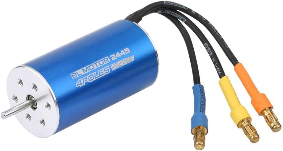
The Types Of Brushless RC Motors are discussed in this article. The brushless motors that RC cars make use of, are RC motors. RC motors are of two types- inner rotor in runners and outer rotor or out runners.

In brushless RC Motors, the electromagnets (poles) are fixed and the permanent magnets are on the spinning part of the engine. The permanent magnets of the in runner brushless motors are housed inside the electromagnets. In the out runner motor, permanent magnets and electromagnets are opposite to each other.

Types Of Brushless RC Motors- FAQs

How do I choose a brushless RC motor?

There are two types of RC motors as discussed above, the inrunners and outrunners. The factors on which a brushless RC motor’s efficiency depends are- speed, size, power etc. Here are the details-

Speed: KV number denotes RPM i.e. the speed of the motor. More the KV, the higher the speed. 

Size: For the right size, pick a motor that fits the RC car/ drone properly.

Power: The power (Watts), should be high. For power, check the Voltage of the motor pull denoted by Amps. It gives the right Electronic Speed Controller (ESC). 

Read more…Two Surge Protectors In One Outlet: Exhaustive FAQs

Types Of Brushless RC Motors
RC Car Brushless Motor; Image Credits: amazon.com

What’s the fastest brushless RC motor?

The US-based company Traxxas is probably the most famous name in the world of RC cars. They produce both electrically controlled and nitro radio cars, trucks, off-road vehicles, boats, and even drones.

The Traxxas X0-1 is a fast RTR RC electric car. It can reach 0 to 60-mph in just 2.3 seconds and in the long run, can reach 100-mph in 4.92 seconds. It is powered by a large electric brushless motor that provides high speed driving to help the car break all records. It is available as a kit car also.

Traxxas XO-1 | Fastest RC Car | 100 MPH RC Car | Traxxas
Traxxas X0-1 RC moror with car kit; Image credits: traxxas.com

What is the most powerful RC motor?

The MGM Losi 5-T brushless motor is regarded as the most powerful RC motor. The model comes with soldered battery, PC cables and motor connectors for providing very high power.

The additional features of MGM brushless RC motor are-

  • Five windings
  • PC connectivity for reading data from ESC
  • Mechanical air cooler inside the motor
The most powerful ESC + MOTOR combo for RC cars  - MGM Losi 5-T
MGM RC motor; Image Credits: mgm-controllers.com

How do you size a brushless motor?

Non-brush motors use a standard number scheme to define their body size and Kv ratio. For example: There is a 5055-3000Kv brushless outer rotor motor. We seperate the numbers as follows: [50] [55] – [3000].

[50] shows the motor’s diameter mm; (here -50mm)

[55] shows the motor’s length in mm; (here -55mm)

[3000] shows the Kv rating; (here- 3000Kv). The Kv rating is the ratio of a motor’s RPM (K) and voltage (v) with no load. E.g- a brushless motor of 3000 Kv powered by a 12V supply can produce 36,000 RPMs (3000×12).

Read more on….Types of brushless motor: with their applications

How do RC brushless motors work?

The main difference between a brushed and a brushless RC motor is the way they change currents in their coils. Brushed motors use brushes and commutators while brushless ones use electrical commutation.

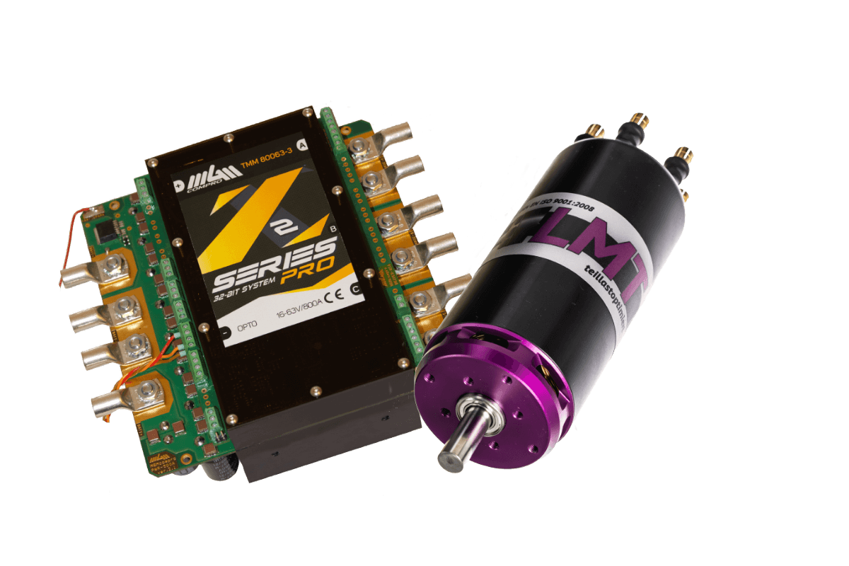
Brushless RC motors need a controller that determines when to change the current direction in the wires on the basis of the relative position of the wires and the magnets. This is sometimes called brushless control and in the RC systems, this is known as brushless ESC (electronic speed control).

Why do Brushless RC motors have 3 wires?

Brushless RC motors have 3 wires unlike the brushed RC motors that contain 2 wires. Brushless motors are 3-phase systems that require more complex circuitry which controls the AC current needed to drive them.

An RC brushless motor consists of some three-wire coils that create electromagnetic forces. At any point of time, one wire is powered, one is grounded and one works as the sensor. The ESC switches current between the wires that creates push and pull and makes the rotor spin.

Can brushless motors work without ESC?

In BLDC, the DC to AC conversion is done electronically. To do that, electrical devices need to know what angle the motor remains at, so there is a sensor that feeds that information back to the controller.

The ESC( Electronic speed control) is in control of all of this. It switches the power at the correct time and keeps the motor rotating. This is considered a vital part of the motor, as it replaces the brushed DC motor’s commutator. There is no way to make the motor do anything useful without a brushless motor controller.

71NUwpcwidL. AC SL1500
Brushless RC motor ESC (Electronic speed control) ; Image Credits: amazon.com

Can brushless motor have two wires?

Brushless motors having 3 wires last longer, rotate faster, and help batteries sustain. The ESC controller makes the rotor magnet spin. Without the ESC, it is not possible to construct a brushless RC motor.

If a brushless motor has only two wires, it will act as a one phase AC motor. Since brushless RC motors are three phase motors, they need two power controlling wires and an additional wire for controlling speed, direction and sending feedback. Some motors have up to 7-8 wires for higher phase systems.

Read more….How to test a capacitor with a multimeter: Complete insights and FAQs

How is brushless motor ESC calculated?

The ESC is an electronic circuit for changing the speed of a vehicle, its direction, and to act as a flexible brake. Brushless ESCs enable 3 phase AC power such as variable frequency drive to make motors work.

We should choose the ESC higher than the amps the motor pulls. If it pulls 20 amps, the ESC should be higher than 20 amps. RC helicopters need ESC as high as 50%. For RC cars, the ESC is 30% above the amps. For maximum performance, efficiency and safety, we must take an ESC at least 10 amps higher than the RC motor rating.

Direct Current Examples:Detailed List of Applications and Examples on DC current uses

Direct current is a current which flows in One Direction without changing its polarity with time.

This article will discuss Direct Current Examples such as DC generator, DC motor, battery, electronic circuits, electroplating, solar power supply, high-voltage direct current transmission, etc.

Some Direct Current Examples:

DC generator

We know that generators can be either AC or DC type of generator, the design of DC generators is very much simple, parallel operations are more straightforward, and the system is mostly stable.

DC generator is a type of generator that converts the mechanical form of energy into DC electricity, this kind of generator generates DC power supply.

And that DC power generated from DC generator is used for testing purposes in different laboratories, used for charging batteries, exciting the alternators, and can be used as a portable generator that supplies small power, can be used for driving motors, etc.

DC Motor

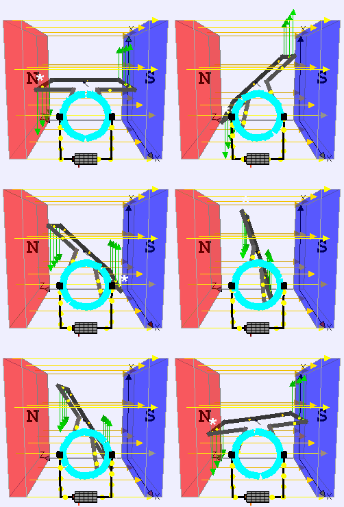
DC motor is an application of DC electric current which converts the direct electric current into mechanical energy creating a magnetic field.

The magnetic field generates the DC powers due to the attraction and repulsion in the magnetic field, and the rotor starts to rotate. DC Motors are used where high torque or accurate speed control over an extensive range is needed.

There are different types of DC Motors which have various applications, such as Elevators, conveyors, rolling mills, Trolleys, Cranes, heavy planers, steel mills, locomotives, excavators, drilling machines, etc.

Battery

Different types of batteries are available that can be recharged by using external power supply set as Nickel- metal hydride, Lithium-ion, Nickel-cadmium, lead-acid, lithium-ion polymer, and other alkaline rechargeable batteries.

While recharging any battery DC is required, DC power supply is used for recharging any battery, as with DC, the electron will flow in one constant direction back into the battery creating the potential difference needed when the battery is fully charged.

An Alternative Current (AC) cannot be used for recharging a battery because the positive half of the AC cycle will charge the battery, where the negative half of the AC cycle will discharge the battery. While recharging the battery, the specification of the battery must be taken into consideration and adjust the current to the proper levels.

Electronic Circuits

Electronic circuits are the concept of MOSFET, BJT, diodes, transistors, logic circuits, integrated circuits, etc.

As DC does not change its polarity with time, with constant and stable magnitude value, there is no power factor or the phase shift, so for proper biasing of the transistor, diode, or any other electronics element, constant DC is preferred.

As AC does not maintain any direction of current flow as it reverses direction periodically, the operation of any electronic components is not possible with an AC power supply.

For example, for proper operation of IC, any IC needs a ripple-free and pure DC power supply as input to generate the required output. Electronics are primarily digital devices that operate using either on or off or high or low signals. When AC is used as a power supply for electronic circuits as for the frequency of AC supply, every second generates lots of on or off signals, which is harmful to the electronic circuit operations.

The processor of the electronic circuit won’t be able to determine the difference in on or off signal in case of any e noise present in that AC signal. While using DC power supply to the electronic circuits, the biasing of any circuit element can be determined or controlled easily. DC is very stable, easy to manage, and accurate; using DC supply to electronic circuit makes it easy to handle or operate any electronics circuit.

Many electronics use an adaptor to convert AC to DC as generally power supply at home is AC power supply, so for proper operations, for example, flashlight charger, television adaptor, computer adaptor, electrical vehicle adaptor phone charger, etc.

Electroplating

For the electroplating procedure, a DC power supply is preferred over AC. Electroplating is a process in which a metal gets deposited over other metal plates in the presence of metal salt.

When DC supply is used in electroplating, one metal gets oxidized, and the ions from that metal get dissolved in the electrolytic solution and then get reduced at the other metal, which is known as electroplated metal while forming a cote on the electroplated metal of electroplating ions.

As for the principle of electroplating, each metal plate must be maintained at opposite polarity at constant during the continuous procedure, which is only possible by supplying a DC. If an AC supply is used, the polarity of both metal plates or electrodes will change continuously, and the ions will oscillate back and forth between electrodes or metal plates where electroplating is not possible. Even if pulsating DC can be used as the direction of the current is not changing with time.

Solar Power Supply

Photovoltaic cell converts the light into a DC using photovoltaics effect, so the power generated from a solar panel is a DC power.

Photovoltaics system uses a solar panel that receives sunlight directly and then converts that light into electric power, while the electricity generated is DC, but can fluctuate with the intensity of sunlight, so before practical use, that DC voltage is required to convert into desired DC voltage or AC, by the use of filters or inverters.

Many photovoltaic power systems are connected to the grid for use on a larger scale, such as satellites, Lighthouse, batteries, etc. By using a grid-connected photovoltaic system, the capacity of any photovoltaic system can be maximized to 10 kilowatts for different requirements of the consumers.

Installing solar panels
Image Credit: “Installing solar panels” by OregonDOT is licensed under CC BY 2.0

High Voltage Direct Current (HVDC) transmission

HVAC stands for high voltage direct current, which is used for power transmission over enormous distances.

High Voltage Direct Current (HVDC) is preferred over High Voltage Alternating Current (HVAC) for transmitting power of more than 600 km. So transmitting power using HVDC through a long transmission line is way cheaper than that of HVAC For distance over break-even distance.

undefined
Image Credit:Diagram costs over line length (distance) in comparision HVAC 3-phase systems versus HVDC systems By wdwd – Own work, CC BY 3.0,

As for transmission lines, HVDC has only required two conductors where HVAC requires three or more than three conductors, HVDC has a uniform magnetic field with constant magnitude throughout the transmission, so HVDC has relatively lower losses than HVAC transmission. The power flow in HVAC lacks compatibility relative to HVDC, and intelligence between asynchronous systems for intelligent grids while using HVDC is relatively more straightforward than HVAC. In DC, there is no frequency or phase shifts.

Telecommunication

The telecommunication network uses a DC power supply, as negative 48 volt DC is found in the landline; the AC power supply is not in the used invoice line because the AC power supply will disturb and disrupt communication.

DC power supply is not restricted to any frequency vibration or landing power factor in telecom. DC power can be easily stored for backup in telecom buses. The battery is used, which provides a DC power supply without any power conversion loss.

Types Of Brushless Motor: With their Applications

In this article, we are going to discuss the Types Of Brushless Motor. This type of electrical motor has no brushes. Brushes are sliding devices that let the electricity flow into the copper coil of the engine.

Brushless motors are of many types. In terms of design it has two types- in runner or inner rotor or out runner and outer rotor. In terms of sensors- sensored and sensorless. In terms of number of poles- single pole and multiple pole. In terms of power signal type- sinusoidal and trapezoidal Brushless motors are there.

Explain inner and outer rotor brushless motor.

Inner rotor and outer rotor are the classifications of brushless DC motors on the basis of design. The magnet used in the motor is the rotor and the winding is the stator. 

Magnets in BLDC help the motor to turn. The stator provides an attractive or repulsive charge towards the magnet and that spins the motor. For the inner rotor BLDC, the rotor is on the inside and the stator is on the outside. For an outer rotor, the design is reverse, i.e. rotor outside and stator inside. 

BFFN h4DpoP8iz8In5BEwANMISqMiZZPn5eNd6s97zKBStOtFmMOVLJ16bu9M3EfPUokUgU0I0nwl4IGupbhSRQsUEDWW3QvlLdSX g2xvynzQT 5Wm3FpWUXGD8pcESes2GS85R
Medvedev, Stator Winding of a BLDC Motor, size by no, is licensed under CC BY-SA 3.0

Explain sensored and sensor less brushless motors.

It is very clear from the name that this division of brushless DC motors comes from the existence of sensors. If a BLDC has sensors inside the motor then it is sensored, otherwise it is sensorless BLDC.

Sensored BLDC motors have positional sensors that feed positional data to the controller and ensure that the driving pattern properly syncs with the rotor position. A sensorless BLDC has magnets in the rotor and to the motor edge. As the engine speeds up it begins to produce electro-motive energy in the stator coils.

Read more on…. What is Mutual Inductance? | All important concepts and 10+ formulas you need to know

Explain single and multi pole brushless motors.

Pole in Brushless DC motors refers to the number of permanent magnet poles for the rotor. Single pole BLDC motors are a pair of single-pole brushless motors. Multi pole BLDCs have up to four pair of poles.

Multi pole BLDC motors have multiple pairs of poles, allowing for smooth rotation, improved performance at lower speeds and increased durability. A single pole motor cannot achieve this. Typical applications for such motors include pumps and process control applications where speed is essential.

Types Of Brushless Motor- FAQ

Are brushless motors DC or AC?

Brushless or BLDC motors are technically DC synchronous motors but are called DC motors. So, the obvious question arises: why do we call it DC and is it correct? Well, it is correct as the supply current is DC.

A BLDC motor has a shaft and a rotating rotor. So it has to be AC as the magnetic field should be changing to keep the rotor rotating. If we use DC supply, the rotor will stop after going to a fixed position. BLDC has an inverter that converts the DC supply into AC that is either built-in or external.

What is the fastest brushless motor?

It is quite arguable and ambiguous as to which is the fastest brushless motor. The word “Fastest” can suggest a motor with very high RPM,or a motor that can fly the FPV drones real quick. 

Size, speed and RPM constant are the factors to keep in mind while choosing a brushless motor. We should choose a BLDC with higher KV. KV is RPV or revolutions per volt. If voltage increases, the motor spins quickly. Here’s a list of some brushless motors that runs very fast and efficiently-

  • ‌Traxxas
  • ‌Iflight
  • ‌Crazepony
  • Betafpv
sE64v36q4pg04rNIlag1sISotXKx5pqweEflerd5SJQffQKZpDh dHsOiXdi5PHbgi0No1w83UG7FG7vagUgSDO 3OoqGjP p0oDwAihCJRg EQeeYR8Mqr2xqG7 84N3UWWPyC
Traxxas Brushless Motor; Image credits: Traxxas.com

BLDC motor applications:

Brushless DC motors or BLDC motors are very important components in electronic devices like Electric vehicles, HVAC, washing machines, compressors, industrial robots, hard drives, CD and DVD players etc.

Following are some applications of BLDC-

  • ‌Industrial use in linear and servo motor, robot actuator, extruder drive motor, CNC machine feed drive etc.
  • ‌Used in home appliances like fans, dryers, pumps, washing machines, blowers etc.
  • ‌Used in the aviation industry for making small drones and also in the healthcare sector.

Why are BLDC motors widely used in industry?

Industrial motors prefer BLDC as main equipment in many devices. They are highly efficient, compact in size and easy to maintain. Nowadays the cost of these motors have also decreased due to the rise in usage.

Manufacturing processes require precise control in motion and stable operation for decent performance in actuation, positioning etc. BLDC produces high torque at low speed that is good for cranes, conveyor belts. Also, some of them are highly durable and can be used for up to 30000 hours. This is why they are heavily used.

Which are the advantages of BLDC motor?

Brushless DC motors are free of commutators or brushes unlike brushed DC motors. Better Longevity, speed and acceleration, less noise and many aspects make BLDC motor a great choice for varied uses. 

Here are the main advantages of BLDC motor-

  • It does not have brushes that restrict speed, produce noise and dust.
  • It can generate more torque at high speed.
  • It has high efficiency and longer lifespan due to lack of friction loss.

Other advantages of BLDC include small size, fast response, better heat dissipation etc.

Why BLDC motors are preferred in high rpm applications?

Brushless DC motors have great speed vs. torque characteristics that makes them suitable for using in high RPM machines. The electromagnetic inference, noise and losses are also less in BLDC motors.

Mechanical power= Torque * speed. For better power we have to increase either of them. In BLDC, when we apply the brake, the torque increases and the speed of the motor goes down maintaining power. Also, the compactness of BLDC allows it to be used in many modern electronic equipment that need high RPM.