How to Remove a Crankshaft Pulley: A Comprehensive Guide

how to remove crankshaft pulley

Removing a crankshaft pulley can be a daunting task for many DIY mechanics, but with the right tools and a step-by-step approach, it can be accomplished efficiently. This comprehensive guide will provide you with the necessary information and technical details to successfully remove a crankshaft pulley from your vehicle. Understanding the Crankshaft Pulley The crankshaft … Read more

Is A Boiler Electric Or Gas? 13 Facts on Different Boilers

320px Gas boiler Junkers 1 172x300 1

In this article, the topic, “is a boiler electric or gas” with 13 facts on different boilers will be discuss in a brief manner. The entire modern boilers are operating with the electricity.

A boiler can be electric or gas both. The electric boilers are transforming the electricity into heating in spite of burning the fossil fuels. A boiler which is driven by boiler is appropriate for the properties which are not connected with the gas network or small size apartment or flat with a lower demand hot and heating water.

Is a boiler electric or gas?

After remove the access panel of the heater from the side of the boiler and look for the pilot light. If we can observe a pilot light is present in the heater, then we can say that it is a type of gas boiler. Electric heaters do not come up with such lights.

How to know the type of boiler?

In general there are three classification of any boiler. The first classification is combi boiler, second classification is heat boiler and last one is system boiler.

How we can understand which type of the boiler is belong is describe below,

Combi boiler:-

A combination or combi boiler is a type of gas boiler which is combination with the central heating system water heating system into a single part body to make hot water as requirement. A separate tank for the heating the water is not required for the combi boiler. The efficiency of the combi boiler is more effective.

Combi boiler work as a one gas boiler system for this reason the space requirement for this is very minimum in a short place easily combi boiler easily can be installed.

Recognize of a combi boiler:-

When we observe a boiler easily can be recognize the combi boiler by its size. The size of the combi boiler is small size or medium size and installed in the apartments for full filling the demands of the hot water.

Five copper tubes are comes from the bottom section of the boiler and there will be no presence of the external pump or cold water tank and hot water tank for the unit of heating system is together with a single body unit.

Heat boiler:-

Another term for the heat boiler is regular boiler. The heat boiler not providing the hot water demand in the way combi boiler does. The hot water is store into the hot water storage tank until the hot water is needed to be distributing to a shower or tap.

Heat boiler system contains both the hot storage and cold storage for this reason a large amount of space is required.

Recognize of a heat boiler:-

When we observe a boiler easily can be recognize the heat boiler by its size. The size of the heat boiler is larger and installed in the apartments for full filling the demands of the hot water.

The external pump system is needed for the heat boiler and also both cold water tank and hot water tank for the unit of heating system is present. Two copper tubes are comes from the bottom section of the boiler.

System boiler:-

System boilers heat the central heating system and also generate hot water for the water storage system. The system boiler directly takes water from the mains as converse to using an expansion and feed tank just like a regular boiler.

In generally where high amount of hot water is required in that case system boiler is needed. The system boiler at a same time in two bathrooms hot water can provide without using any cold water tank.

Recognize of a system boiler:-

When we observe a boiler easily can be recognizing the system.

Three copper tubes are comes from the bottom section of the boiler and there will be no presence of the external pump. In the system boiler hot water tank for the unit of heating system can be observe.

How to identify gas boiler?

When we observe a boiler easily can be recognize the gas boiler by its size. The size of the gas boiler is larger and installed in the apartments for full filling the demands of the hot water. The external pump system is needed for the gas boiler and also both cold water tank and hot water tank for the unit of heating system is present. Two copper tubes are comes from the bottom section of the boiler.

Advantages of gas boiler:-

The advantages of the gas boiler are listed below,

  1. The cost of the gas boiler is cheaper than the electric boiler.
  2. Gas boiler can full fill the high scale demand for hot water and heating.
  3. Installation cost for the gas boiler is low.
  4. More verities of the gas boiler mean more available options in the market.

Disadvantages of the gas boiler:-

The disadvantages of the gas boiler are listed below,

  1. For installation a large amount of space is required.
  2. Lots of moving parts are present in the gas boiler for this reason lots of problem can be arise.
  3. Leakage of the carbon monoxide can be more.
  4. Maintenance is required in a year.
320px Gas boiler Junkers 1
Image – Gas boiler;
Image Credit – Wikimedia Commons

Does a boiler use gas or electricity?

Without electricity the boiler could not runs its function. For running may be little amount of electricity is needed but without electricity the boiler could not run. For display screen, thermometer and also back lighting bulbs electricity required. The electricity also helps to keep the apartment heated and supplied hot water. For ignition of the boiler electricity play a important role.

Advantages of electric boiler:-

The advantages of the electric boiler are listed below,

  1. The parts of the electric boiler are very less moves for this reason problems are very less arise.
  2. Installation of an electric boiler is easy there is not required any flue pipe.
  3. Carbon monoxide leakage can be appear in the electric boiler is zero percentage.
  4. Operation of the electric boiler is not noisy.
  5. Emission is not appearing while heat the apartment.

Disadvantages of electric boiler:-

The disadvantages of the electric boiler are listed below,

  1. Installation cost of the electric boiler is expensive.
  2. Electricity is expensive comparative to the natural gas.
  3. While defection is appearing in the electric boiler the maintenance cost will be became expensive.
  4. Heating demand cannot match for the large size property.
  5. Most of electricity is create for the burning of fossil fuels.
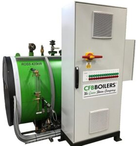
is a boiler electric or gas
Image – Electric boiler;
Image Credit – Wikimedia Commons

How to identify electric boiler?

In general there are three classification of any electric boiler. The first classification is combi boiler, second classification is heat boiler and last one is system boiler.

How we can understand the identification of a boiler is listed below,

  • Recognize of a combi boiler
  • Recognize of a heat boiler
  • Recognize of a system boiler

Recognize of a combi boiler:-

When we observe a boiler easily can be recognize the combi boiler by its size. The size of the combi boiler is small size or medium size and installed in the apartments for full filling the demands of the hot water.

Five copper tubes are comes from the bottom section of the boiler and there will be no presence of the external pump or cold water tank and hot water tank for the unit of heating system is together with a single body unit.

Recognize of a heat boiler:-

When we observe a boiler easily can be recognize the heat boiler by its size. The size of the heat boiler is larger and installed in the apartments for full filling the demands of the hot water.

The external pump system is needed for the heat boiler and also both cold water tank and hot water tank for the unit of heating system is present. Two copper tubes are comes from the bottom section of the boiler.

Recognize of a system boiler:-

When we observe a boiler easily can be recognizing the system.

Three copper tubes are comes from the bottom section of the boiler and there will be no presence of the external pump. In the system boiler hot water tank for the unit of heating system can be observe.

Is a combi boiler gas or electric?

A combi boiler can be both gas boiler and electric boiler. The electric boilers work same as the gas boiler but to generate the central heating system and to warm the water electricity is needed. Only by the electric combination boiler we can warm the water and full fill our desire.

Do all combi boilers use gas?

The simple answer is no. All combi boilers do not use gas to operate the function. A combi boiler can be both gas boiler and electric boiler. The electric boilers work same as the gas boiler but for the generating the central heating system and to warm the water electricity is needed.

Can you have a combi boiler without gas?

Electric combi boilers do not run off gas or oil so the electric boiler is not depend upon the existing heating system to generate heat in the apartments. The installation cost became very less and making fit also easier. The parts for the electric combi boiler is less for this reason maintenance cost also became cheaper.

Is a back boiler gas?

Yes, a back boiler is gas. The size of the back boiler is very less. Compact boiler is attached at the back portion of an open fireplace hearth.

The back boiler is situated behind a gas fire and helps to generate hot water and central heating system.

Is a worcester boiler gas or electric?

Worcester boiler is a type of gas boiler. High energy efficiency, comfort and reliability can be easily got through the Worcester boiler. Mainly the gas, propane and oil fuel differs so as suitability we can choose the boiler for any apartment.

What type of boiler is a Worcester?

Worcester boiler is a type of gas boiler. Greenstar is named for the all   Worcester boiler. Gas, propane and oil fuel is used in this type of gas fired boiler.

Is a vaillant boiler gas or electric?

Vaillant boiler is a type of gas boiler. The working efficiency for this type of boiler is near about 98 percentages. Installing an energy efficient vaillant boiler in your home can make a huge difference in keeping your energy costs down.

What type of boiler is a Vaillant Boiler?

Vaillant boiler is a type of combination gas boiler. The working efficiency for this type of boiler is near or more than about 98 percentages.

Is a baxi boiler gas or electric?

A baxi boiler is a gas boiler and 180 litres storage provides faster, energy efficient and reliable heat and hot water.

Is a system boiler gas or electric?

An electric boiler relies on electricity to generate heat, and they can be highly effective at warming a home or a home’s water supply. An electric boiler tends to be less expensive than gas boilers, but you must do your research on local costs to before hiring a contractor.

What type of boiler is system boiler?

System boiler is electric boiler. To boil the water required to keep us warm and comfortable, system boilers use the mains as a heat source or sometimes bottled gas or oil.Three copper tubes are comes from the bottom section of the boiler and there will be no presence of the external pump. In the system boiler hot water tank for the unit of heating system can be observe.

Conclusion:-

A boiler can be both electric and gas.
Fluidized Bed Reactor Design: Diagram, Parameters, Applications, Advantages and Disadvantages

Fluidized Bed Reactor Graphic.svg

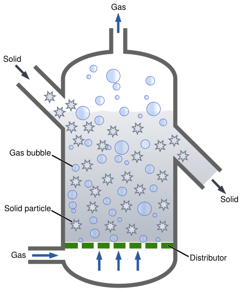
In this article, the topic named “Fluidized bed reactor design” and fluidized bed reactor design related facts such as, Design, Diagram, Parameters and Applications, will be summarize.

The fluidized bed reactor is a classification of reactor device which is mainly carry out a wide range of multiphase chemical reactions. In the fluidized bed reactor a fluid substance which can be stay at liquid or gaseous state is go through at a high speed by a solid granular material. The procedure terms as fluidization.

In various applications of industrial fields fluidized bed reactor is used.

Fluidized bed reactor diagram:

Fluidized-bed reactors are the most popular reactor configurations employed for reactions involving solid reactants. In the FBR, a fluidization medium (gas or liquid) is passed through the bed of solid reactants at high enough velocities to suspend the solid and cause it to behave like a fluid.

The diagram of the Fluidized bed reactor is given below,

  • The fluidized bed reactor is a classification of reactor device which is mainly carry out a wide range of multi phase chemical reactions.
  • In the fluidized bed reactor a fluid substance which can be stay at liquid or gaseous state is go through at a high speed by a solid granular material.
  • The procedure terms as fluidization, notify principally important favor to the fluidized bed reactor.
  •  In various applications of industrial fields Fluidized bed reactor is used.
  • Fluidized bed reactor is widely used in the commercial scale to laboratory.
  • Inside the fluidized bed reactor when the velocity of the fluid on the substance of the solid is increases the bed reactor go up to a period where the fluid force is suitable to adjust balancing the weight of the solid substance. The period of the process is identified as incipient fluidization and happened at the lowest velocity of the fluidization.
  • In the coal gasification the fluidized bed reactor is used first.
fluidized bed reactor design
Image – Basic diagram of a fluidized bed reactor;
Image Credit – Wikipedia

Fluidized bed reactor design parameters:

The parameters which are depend upon the Fluidized bed reactor are listed below,

Mechanical design of fluidized bed reactor:

With the help of Navier – Stroke equation the behaviour of the fluidization of a solid particle can be deriving. Fluidization is appear in the case of the fluid is flow in upward direction and used to mobilized and eliminate solid particle.

Three key equations used in fluidization prior of building and designing the project which is included to the terminal velocity of spherical particle as well as fluidization velocity based off of the particle’s Reynolds number.

The terminal velocity of a spherical particle can be expressed by this equation,

vmax = (πr2)* d2 x (ρsolid – ρfluid) *g / 18*μfluid

The fluidization velocity of a particle with a Reynolds number less than 20 can be expressed by this equation,

Vmin = (πr2)* d2 x (ρsolid – ρfluid) *g*∈3*φ/150*μfluid*(1-∈)

The fluidization velocity of a particle with a Reynolds number more than 1000 can be expressed by this equation,

gif.latex?%5Cdot%7BV%7D %7Bmin%7D%20%3D%20%28%5Cpi%20r%5E2%29%20*%5Csqrt%7B%5Cfrac%7Bd%20*%20%28%5Crho %7Bsolid%20%7D %20%5Crho %7Bfluid%7D%29*%20g%20*%20%5Cvarepsilon%20%5E3%20*%20%5Cphi%7D%7B1

Where,

gif

is denoted the Flow rate of the fluid

r = is denoted the radius of the particle which is flowing in the fluid and value is 10 millimetre

d = is denoted the diameter of the particle which is flowing in the fluid and value is 0.15 millimetre

ρsolid = is denoted the density of the particle which are flowing in the fluid and value is 1.5 kilogram per cubic meter

ρfluid is denoted the density of the flowing fluid and value is 1.2 kilogram per cubic meter

g is denoted the Gravity and value is 9.81 meter per square second.

μ is denoted the viscosity of the flowing fluid and value is 1.8 Pascal second.

φ is denoted the sphericity which is flowing in the fluid of the particle and value is 1.0.

Fluidized bed reactor applications:

In the waste water preparation Fluidized bed reactor widely used.

Waste water preparation:-

  • In the waste water preparation the fluidized bed reactor is used for this reason the cost can be minimize and represent as cost effective preparation for the waste water which containing recalcitrant pollutants (The mixture which is bio gradable or non biodegradable in a slow process which identified as, recalcitrant mixture and group from facile halogenated hydrocarbons to complicated polymers.)
  • The fluidized bed reactor is widely used in the waste water preparation although in the large scale industrial field the fluidized bed reactor is used for the advanced oxidation method and also in the laboratory.
  • In the fluidized catalytic cracking fluidized bed reactor is used which is introduced in the 1940s.
  • Anaerobic fluidized bed reactor in modern generation used as anaerobic platform to achieve high strength and also for the high solid waste streams like corn ethanol thin stillage and sludge of the municipalities.
What is Zero Liquid Discharge Diagram
Image – A zero liquid discharge process diagram that highlights how wastewater from an industrial process is converted via a ZLD plant to solids and behaved water for reuse;
Image Credit – Wikipedia

Fluidized bed reactor advantages:

The advantages of the fluidized bed reactor is listed below,

  • Mixing of the particles is uniformly
  • Uniform Temperature gradient
  • Ability to perform the reactor even in the continuous state

Mixing of the particles is uniformly:-

For behave like intrinsic fluid in the solid material the fluidized bed could not getting bad experience for the mixing in the packed beds. The complete and fine mixing in the fluidized bed is allow to make a uniform product that is not easy to achieve so easily in the other designs of the reactor. The deduction of the axial and radial concentration gradients even accommodate for better fluid solid contact, which is needed for the quality and reaction efficiency.

Uniform Temperature gradient:-

A lot of range of chemical reaction needed addition of heat or removal of heat. Local hot spot or cold spot beneath the reaction bed, at every turn a difficulty is packed beds, are avoided in a fluidized bed like as fluidized bed reactor.

In another classification of reactor, the difference of the local temperature mainly in the hotspot can make as a result of product degradation.

For this particular reason the fluidized bed reactor is appropriate for exothermic reaction. Observers are also observed that the bed to surface heat transfer coefficient for the fluidized bed reactor is higher.

Ability to perform the reactor even in the continuous state:-

The fluidized bed character of these reactors is to accommodate for the efficiency to continuously pick off product and establish new reactants into the reaction vessel.

Actions of a continuous method situation give away manufacturers to produce several of products more efficiently due to the elimination of startup situations in batch methods.

Fluidized bed reactor disadvantages:

The disadvantages of the fluidized bed reactor is listed below,

  • The size of the reactor vessel is increases
  • Pressure drop and pumping is needed
  • Particle entrainment
  • Pressure loss scenarios

The size of the reactor vessel is increases:-

In the fluidized bed reactor the materials are expand in the reactor for this reason a large size reactor vessel is needed than for a packed bed reactor. The size of the reactor vessel large means need to spend more initial cost. The fluidized bed reactor became very expensive.

Pressure drop and pumping is needed:-

The necessity for the fluid to break the material which stays at solid state requires that a higher fluid velocity is present in the reactor of the fluidized bed reactor.

For this particular reason, more pumping power is required and also higher energy costs needed. In addition, the pressure drop is attached with the deep beds thus also requires additional power of the pumping.

Particle entrainment:-

The high gas velocities present in this style of reactor often result in fine particles becoming entrained in the fluid. These captured particles are then carried out of the reactor with the fluid, where they must be separated.

This can be a very difficult and expensive problem to address depending on the design and function of the reactor. This may often continue to be a problem even with other entrainment reducing technologies.

Pressure loss scenarios:-

If fluidization pressure is suddenly lost, because the area of the bed surface may be suddenly start to reduced. This can either be an inconvenience like making bed restart difficult, or may have more serious implications, such as runaway reactions.

The other disadvantages of the fluidized bed reactor are,

  • Lack of current understanding
  • Erosion of internal components

Fluidized bed reactor working principle:

The purpose of the fluidization is to keep the solid particles floating in a direction of upward in a flow of liquid or gas. In freezing, the process of fluidization is occur when the same size and shape of particles are subjected to an upward stream of low temperature air.

The working principle of fluidized bed reactor is describe below,

  • The fluidized bed reactor is mainly working in the flow of co – current.
  • In general the Fluidized bed reactor three different types of particles are used,
  • a. Inert core in which the biomass is created by the help of the cell attachment.
  • b. Cell aggregates.
  • c. Porous particles, in which generally the bio catalyst is soaked.
  • The solid layers refer to the catalytic material in which the chemical reactors are reacted in the fluidized bed reactor adopted by the porous plate which term identified as distributor.
  • In the next step the fluid is forced by the distributor thus the solid catalytic material can goes up.
  • Inside the fluidized bed reactor when the velocity of the fluid on the substance of the solid is increases the bed reactor go up to a period where the fluid force is suitable to adjust balancing the weight of the solid substance. The period of the process is identified as incipient fluidization and happened at the lowest velocity of the fluidization.
  • When the lowest velocity is passed away the volume of the reactor bed is spread and twisted more than like a boiling bowl of water or an agitated tank. The reactor is now placed in the fluidized bed.
  • A bed which is filled with the immobilized enzymes is fluidized with the quick flow of the secondary fluid steam or upward direction flow of layer or mixing with a liquid.
  • Depend on the condition of the operation and the characteristics of the solid phase a wide range of flow regimes can be noticed in the fluidized bed reactor.

Conclusion:

The fluidized bed reactor is used in a wide range of the material processing industrial fields where a good amount of heat and mass transfer is needed in between the particles and mass. The energy is provided in the fluidized bed reactor from the warm gas which one also fluidizes the bed.

How Does a Gas Boiler Work: Complete Beginner’s Guide

320px Gas boiler Junkers

In this article, the topic “how does a gas boiler work” with several facts will be summarize in a brief manner. Gas boiler is a comparative simple design mechanism device.

Process of how does a gas boiler work:

The process working of a gas boiler is given below,

  • At the beginning of the process the source of the heating, which gives the power the whole mechanism of the gas boiler is actually a natural gas. With help of the pilot light the natural gas is ignited and heat up the boiler’s reservoir tank.
  • In the next of the process when thermostat is started automatically or manually the natural gas of the chamber is allowed to ignition. The mechanism of the process is a gas piping systems which have a numbers of dents to creating an effect of jet.
  • After that, the heat exchanger is heated by the heat which is mainly comes from the flame of the natural gas. The heat exchanger of the boiler included with small fins. The fins of the heat exchanger are made with metal which have higher thermal conductivity, around of it have a pipe which is filled by water.
  • The pipe around the heat exchanger is the part of system of central heating. The pipes are go through by the radiators. Home is the place where thermal energy is transferred from the fins of the heat exchanger to the radiator is.
  • Now the heat is radiate. The process accommodates the boiler in any house to heat by a simple constructed thermal exchanger.
  • A pump which is driven by electric is situated in the same line with the piping system. When the water come back to boiler repeatedly the heat is loosen more than the heat is paddled by the home and boiler gets heated again.

In a boiler fuel combustion explosion can be appear when the flame of the burner is came out. The reason behind the fuel combustion explosion in the fuel is happened for loose valve, ignition failure, fault in the gas lines can allow for the build-up of combustion gas in a higher temperature in the vessels of the boiler. The reasons are not only responsible for the fuel combustion explosion but also gasses can be leak for these facilities.

how does a gas boiler work
Image – Gas boiler;
Image Credit – Wikimedia Commons

Gas boiler diagram:

  • A standard gas boiler at the beginning of the process burns the natural gas and heat up water and supply the hot water to the needy. In the process of burning the natural gas a chemical reaction takes place and two by product is produced during this process.The first by product is carbon dioxide and another by product is water vapour.
  • After completing the process the excess amount of waste gas go through by a flue and finally release into the surrounding.
  • Now if we talk about the working principle of the condensing boiler in that case burning the fuel the latent heat of water is produced. Effectiveness of the boiler is increases in this process. For burning up the units are mainly used the vapour and also stretch out additional heat, the water in condensed from the vapour to receive the latent heat.
  • For the heating system of central domestic the units are generally used and heat is cover from the wastage of the gases.
  • The gases are passes by the heat exchanger and the temperature is decreases. After that the gases are condensed and take form of liquid which is directed as condensate. In this way very effortlessly cover some amount of heat which can be ruined. The heat which is used to heat up the cool water, which is comes from the radiator to boiler. A good unit can get a desired amount of energy efficiency which is near about 90%.
  • The gas boilers are all time perfect to use during the replacement of be present gas unit.
  • Perhaps, one of the major efficiency benefits of this unit is the fact it has a pretty large heat exchanger. Large radiators make it possible to lower return temperatures, pushing efficiency higher. An additional benefit is the fact the boiler is cost effective, as the system is considerably under-loaded for the major part of the heating season.
  • Today such boilers become more and more popular due to the great savings they ensure. However, many people state they are prone to major breakdowns. That really depends on the manufacturer, venting and maintenance. Such models are more expensive to buy, but still there are many grants available, which can help to cut down expenses.
  • Gas boiler diagrams can help to find out how the boiler works and whether it suits your needs for heating and hot water. Today they’ve become indispensable during installation of any gas unit. Before buying, make sure the manufacturer has provided you with one.

Gas boiler dimensions:

The gas boiler dimensions which are used are depending upon the size with the number of shower or bathroom. The dimensions needed for the gas boiler in the room is listed below,

  1. For 2 bedrooms house minimum 26 kilowatt to maximum 29 kilowatt gas boiler is required.
  2. For 3 bedrooms house minimum 29 kilowatt to maximum 35 kilowatt gas boiler is required.
  3. For 4 bedrooms house minimum 29 kilowatt to maximum 35 kilowatt gas boiler is required.
  4. For 5 bedrooms house minimum 35 kilowatt to maximum 35 kilowatt gas boiler is required.

How does a gas back boiler work?

The lifespan for the boiler is in between 10 years to 15 years. If the maintenance of the boiler can be done in a proper way then the function of the boiler can go more longer.

A gas back boiler use to heat a fireplace with the help of gas fire or electricity. The cold water comes from the storage tank and reaches to the primary system. After reach to main system the cold water begins to warm and after heating when the temperature of the cold water reaches to desired position, a pump is used to distribute the hot water to output.

The reasons behind the replace a gas boiler:-

The reason behind the replace of a gas back boiler is listed below,

  1. The parts of a back gas boiler maintained and repairing is very difficult for the reason of lack of spare parts.
  2. Back gas boiler are not energy efficient whereas, the modern gas boilers are energy efficient for this reason the electricity bill of the a back gas boiler is too high and electricity bill of a modern gas boiler is too low.
  3. With reports of explosions a back gas boiler is very dangerous.
  4. For government safety and regulation the back boiler are no longer to establish.
800px Energy intensity of economies OWID.svg
Image – :Energy intensity of economies Energy intensity level of primary energy is the ratio between energy supply and gross domestic product measured at purchasing power parity. Energy intensity is an indication of how much energy is used to produce one unit of economic output. Lower ratio indicates that less energy is used to produce one unit of output;
Image Credit – Wikipedia

How does a gas boiler thermocouple work?

Gas boiler such as, gas water heater for maintaining unchanged temperature maintain a periodic cycle which follow on or off system. A huge range of gas boiler contain standing pilot light. Every gas boiler who carried standing pilot light has thermocouple. The function of the thermocouple is to stay open the gas valve when pilot is tight.

Water heater and boiler not the same device but their function is almost same. When the point of maintenance comes at fixed temperature at that time the working principle of water heater and boiler is same. The major difference in between the heating system and boiler system is heating system works in a closed loop system.  

Hot steam or hot water is supplied for a under floor heat system or baseboard radiant. Improper a heating system which turns refilled by cold water whenever hot water is used, with the help of the boiler same water is circulates again and again. Reheating the temperature is important for keeping the house warm.

Will gas boiler work without electricity?

No, without electricity the boiler could not work.

For the working purpose of the boiler need very little amount of electricity but still to run the function of the boiler electricity is required. For ignition of the boiler electricity is required and also to run the function of smart thermostats, back lighting and display screen to heat the home electricity is supplied.

Conclusion:

When a gas boiler is working a valve is connected to a gas boiler opens and natural gas is enter to the combustion chamber which is stays at sealed position. After that a ignition system which is driven by electricity or permanent pilot. Then natural gas is ignited and start to burn the natural gas. Hot jet are connected to the heat exchanger within the boiler and heat is transfer from the boiler to water that flows over the heat exchanger.

23 Facts On Radial Stress: The Complete Beginner’s Guide

radial stress

In this article we will discuss different facts related to Radial Stress.

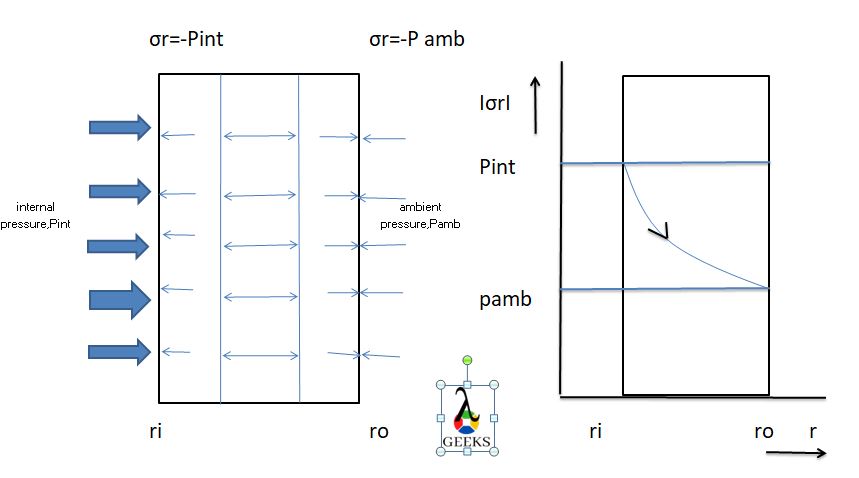
Internal pressure and external pressure compress the pressure vessel radially, resulting compression stresses called radial stress, the sign convention in common use regards compressive stresses as negative. Radial stress is represented by σr

All the three principal stresses (hoop, axial and radial) act on a pressure vessel are mutually perpendicular to each other. Among all the three stresses σr acts in the direction of radius of the cylinder or sphere.

What is Radial Stress?

Pressures act in different directions on a cylindrical or spherical object  which are named as Axial, Radial and Tangential stresses.

The Radial Stresses can be formulated as a function of internal pressure and ambient pressure and the inner and outer radii of a pressure vessel. On the inside surface of the cylinder, the σr is the same as the internal pressure.

On the outside, it is the same as the external pressure ( 14 psi or 0.1 MPa). Through the thickness of the cylinder, it varies almost linearly between those values. If we consider a cylindrical pipe carrying fluid, different types of loads like weight loads(pipe weight, fluid weight, etc.), pressures( internal and external design and operating pressures), temperature change, occasional loads(slug force, surge force) create stresses in a piping system.

These loads try to deform the pipe and due to inertia effect the pipe will create some internal resisting force in the form of stresses.

What is Radial Stress in Pressure Vessel?

The Radial Stresses act differently on a pressure vessel depending on its wall thickness and the shape of vessel.

If the inner surface of a cylinder experience pressure, then the maximum stresses will develop in the inner surface and if the outer surface undergo pressure force then maximum stresses will be acting on the outer surface.

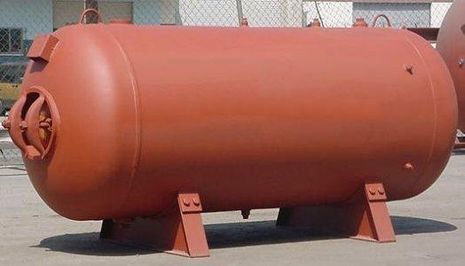
Pressure Vessels are large containers specially designed to keep liquids and gases, the inside pressure is always different from the outside pressure, the inner pressure of a pressure vessel is usually maintained at a higher side. Cellular organisms and arteries of our body are the natural example of pressure vessels.

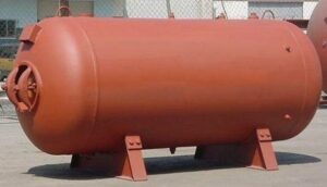
465px Modified Hanson steelwatertank 1
A Welded Steel Pressure Vessel; Image Credit: Wikipedia

Vacuum containing pressure vessels are maintained at a lower inner pressure than the atmosphere.

Generally for a pressure vessel we can assume that the material used is isotropic, the strains from the pressures are small and the wall thickness of the vessel is much smaller than outer and inner radius of the container. Aerosol cans, scuba divining tanks and large industrial containers, Boilers etc are the examples of pressure vessels.

What is Radial Stress in Pipelines?

Radial stress in pipelines is due to the internal pressure inside the pipe created by the fluid or gas.

Radial Stress is acting in pipelines in the form of a normal stress and acts parallel to the pipe radius. The value remains within the range of internal design pressure and atmospheric pressure act on inner and outer surface respectively. The σr which is developed perpendicular to the surface is given by σr=-p.

In comparison to other normal stresses acting in pipelines the value of the σr is significantly lesser, for this reason, the Longitudinal stress and circumferential stress are only considered for pipe designing purposes. σr is generally ignored.

How to calculate Radial stress in pipe?

Radial Stress is a normal stress present in pipe wall, acts in a direction parallel to pipe radius.

σr is acting in pipelines in the form of a normal stress and acts parallel to the pipe radius. The value remains within the range of internal design pressure and atmospheric pressure act on inner and outer surface respectively.

Let us consider the σr in a pressurized pipe, the cross-section of the pipe wall is characterized by its inside radius and outside radius.

σr=-Pint

σr=-Pamb

Minus sign is due to the compressive nature of the stresses.

At an arbitrary location inside the pipe wall forces cause compression which is counteract by the material of the pipe wall.

radial stress

Value of the compressive stress through out the pipe wall thickness, the expression for stress distribution inside the pipe wall is given by Lame’s theorem.

The expression for

gif

The expression contains many fixed value like ro, ri, pi, po only radius(r) is only variable.

gif

In other words 

gif

Radial Stress is decreased from inside pressure value to outside pressure value.

Maximum σr is simply the internal pressure value of the pipe

σ rmax=pint

Radial Stress Formula

The normal stress that acts towards or away from the central axis of the cylinder is known as Radial Stress.

A set of equations known as Lames equations are used to calculate the stresses acting on a pressure vessel. In case of a pipe σr varies between Internal pressure and Ambient Pressure.

σr=A-B/r2

σθ=A+B/r2

Where,A and B are the constant of integration and can be solved by applying boundary conditions.

And “r” is the radius which may inner radius or may be outer radius.

Radial Stress Formula for Thick Cylinder

A pressure vessel is considered as thick when D/t< 20 where ‘D’ is the diameter of the vessel and ‘t’ is the wall thickness.

In the case of a thick cylinder, the stresses acting are mainly Hoop’s Stress or circumferential stress and Radial Stress. Due to the internal pressure acting inside the vessel, some stresses are developed in the inner wall of the vessel along the radius of the vessel which is known as the Radial Stresses.

Lame’s equation is used to quantify the stresses acting on a thick cylinder. The σr for thick cylinder at a point r from the axis of the cylinder is given below

This image has an empty alt attribute; its file name is gif.latex

Where ri=inner radius of the cylinder

ro=outer radius of the cylinder

pi=inner absolute pressure

po=outer absolute pressure

At the inside surface of the cylinder wall the σr is maximum and is equal to pi – po i.e. gauge pressure.

Radial stress formula for conical cylinder

The effect of Radial Stress in case of a thin cylinder is not zero but does not worth to consider its effect for design and analysis.

In case of a thin cylinder the hoop stress and axial stresses are much larger than σr, therefore for a thin cylinder the Radial Stress is generally ignored. In case of a thick cylinder σr generated is equivalent to gauge pressure on the inner surface of the cylinder and zero on the outer surface.

Radial Stress Formula for Sphere

The stresses act normal to the walls of the sphere are Radial Stresses.

The σr acting on the outer wall of a sphere is zero since the outer wall is a free surface.

σr formula for a sphere is σr=-pi/2,for mid thickness t/2

σr=-p, for inner radius

σr=0, for outer radius

Is Radial Stress Tensile?

Radial Stresses are always compressive in nature.

The radial Stress in a pressure vessel is generated due to the action of internal pressure exerted by the inside fluid and the ambient pressure on the outer surface. At an arbitrary location inside the wall of the pressure vessel forces cause compression which is counteract by the material of the wall.

pi and pe compress the shell radially, generating σr, as per the convention of continuum mechanics, these stresses are negative.

The σr at the inner and outer radius are respectively

σri=-pi

σre=-pe

The stresses are uniformly distributed through the thickness of the structure, the arithmetic mean of stresses will give the radial stress σr,

σr=(σrire)/2

σr=-(pi+pe)/2      Eq(1)

Where pi=0, pe=0,

Eq(1) gives

σr=-pi/2

σr=-pe/2

Is Radial Stress Negative?

Radial Stresses act in the radial direction of a pressure vessel and just like the tangential or hoop stress it is also

responsible for diametrical deformation of a vessel.

In general Radial Stress is compressive in nature acting between the inner and outer surface of a cylindrical vessel and as per the convention of continuum mechanics, Radial stresses are negative.

Is Radial Stress a Principal Stress?

Yes, Radial Stress is a Principal Stress.

Radial Stress is the stress towards or away from the principal axis of a pressure vessel. In the case of a thick cylinder, the stress distribution is across the thickness of the cylinder. The maximum σr is obtained at the inner radius of the cylinder.

Is Radial Stress Shear Stress?

Shear Stress τ is the component of stress which is coplanar with the cross section of a material.

Due to the shear expansion of a structure Radial stresses are developed which act on the normal direction of the interface. As a result the shear stress strength of the interface is greatly enhanced which in turn greatly improve the ultimate bearing capacity of anchorage structure.

Shear stress classified as Direct shear stress and torsional shear stress. Starting from 1960s, anchorage structure in the form of temporary and permanent reinforcement has been used frequently in Civil as well as Mining Engineerings

Is Radial Stress Normal Stress?

A Radial Stress is a normal stress coplanar to symmetry axis but acting perpendicularly to the symmetry axis.

Normal Stresses are always act in a direction normal to the face of the crystal structure of a material, they exist both in compressive and tensile nature. Radial Stresses are a type of normal stress and compressive in nature.

Conclusion:

To wrap up the article we can state that Stresses acting in the radial direction of a pressure vessel σr have great importance just like the two other principal stresses( Hoop and Axial) especially in designing a thick-walled cylindrical or spherical pressure vessel.

How Do Bones Handle Stress: A Closer Look at Their Remarkable Resilience

how do bones handle stress a closer look at their remarkable resilience

Bones are remarkable structures that can handle stress through a combination of mechanical and biological adaptations. They are designed to withstand various types of loads, including compressive, torsional, transverse, and tensile forces, due to their hierarchical structure and anisotropic nature. Understanding the intricate mechanisms that enable bones to maintain their strength and integrity in the … Read more

Is Boiler A Pressure Vessel: Facts You Should Know

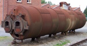
Dampfkessel fur eine Stationardampfmaschine im Textilmuseum Bocholt 300x159 1

In this article we will discuss different facts related to Boiler and Pressure Vessel to know the answer for the query “is boiler a pressure vessel?”

Boilers are a special type of Pressure Vessels.Boilers are common devices for industrial heating and humidification applications. Pressure vessels are large containers or tanks designed to operate at pressures much higher than atmospheric pressure.

Define A Boiler

According to the Indian Boiler Act, a Boiler is a closed pressure vessel with capacity exceeding 22.75 litres used for generating steam under pressure.

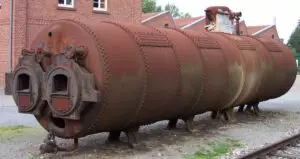
A Boiler is a device used for generating steam for power generation or heating purposes and hot water for heating purposes. Industrial Boilers are designed in such a way-that it can cope with high pressures, Boilers are fabricated by welding thick steel plates together.

Any defects in making a Boiler may result in forces that may create a dangerous situation.

is boiler a pressure vessel
An Industrial Boiler; Image Credit: Wikipedia
465px Modified Hanson steelwatertank
A welded steel Pressure Vessel; Image Credit: Wikipedia

Difference between Boiler and Pressure Vessel

A pressure vessel is a container which contains the fluids ,gases or combination at high pressures. whereas a boiler is a container that contains the liquid that is water such that it can be boiled by the heat source at higher temperatures.

The different facts to know “Is Boiler a Pressure Vessel” are listed below:

 BoilerPressure Vessel
IntroductionBoilers are special type of closed vessels in which fluid mainly water is heated. Heated fluid is then used for different purposes.Basically a closed container with a pressure difference between inside and outside the container. The inside pressure is usually higher than the outside except for some isolated situations.
UsesThe main function of a Boiler is to either produce hot water or steam.Mainly used to store gases and liquids at high pressure.
Area of useDifferent sectors like food industries, beer brewing process, domestic purposes, commercial and industrial uses, textiles, thermal power plants, power sectors, sugar plants etc.Different sectors like gas and oil industries, chemical industry and power plants, distillation towers use Pressure Vessels for various purposes.
Main ComponentsA Furnace is an essential part of a Boiler where fuel is burned to produce heat.The main components of a pressure vessel are shell casing, nozzle, support or saddle and head or end closures.
TypesDifferent types of Boilers are Fire tube boiler, Water tube boiler, High pressure and low pressure Boiler, Horizontal and Vertical Boiler, Externally and Internally Fired Boilers etc.Different types of pressure vessels are autoclaves, high pressure vessels, process vessel, expansion tank, heat exchanger, vacuum tanks, ASME pressure vessel, Boilers, thin walled pressure Vessel etc.
Materials usedSteel. Alloy steel, copper, brass, wrought iron etc are used.Steel, nonferrous materials(aluminum, copper), metals(like titanium, zirconium)plastics, composite, concrete etc.
Boiler Vs Pressure Vessel

These vessels are always designed carefully to cope with the high operating temperature and pressure. In most of the countries, vessels like Boiler and Pressure Vessels over certain size and pressure must follow certain regulating act mainly to ensure compliance with safety, security and design standards.

The use of Boiler starts much before than Pressure Vessel. Sudden rapture of a Pressure vessel or a Boiler can be resembled with hazardous explosion which leads to extensive physical injury and property damage, therefore safety and integrity are of fundamental concern in design.

Boiler and Pressure Vessel Code

American Society of Mechanical Engineers (ASME) develop standards and regulation codes to define and secure Boilers and Pressure Vessels safely, it includes a wide range of rules and directives.

Boilers and Pressure Vessels can be dangerous and may lead to fatal accidents due to this reason design, manufacture, and operation are strictly regulated by Engineering authorities followed up by legislation. In the United States the ASME Boiler and Pressure Vessel Code(BPVC), and in Europe, the Pressure Equipment Directive Code is applied.

An authorized inspector has to sign off on every new vessel constructed, each vessel must have a nameplate with all the required information about the vessel. Across over 100 countries the ASME code is accepted. The adding of the ASME certification mark to your pressure equipment encourages greater trust among your business partners, end-users, and authorities.

Conclusion:

In this article we try to know “Is Boiler a Pressure Vessel ?”. Before wrapping up the article we can say Boilers come under the Pressure Vessel category and Boilers have almost all the characteristics for which we can say Boilers are similar to Pressure Vessels

Read more about  Is Boiler Closed System Or Machine, Boiler Flow Temperature and Is Boiler Energy Efficient.

Does Boiler Pressure Drop: Reasons & 9 Facts You Should Know

Steam Boiler 3 english

In this treatise, the topic “does boiler pressure drop” with Reasons & 9 several facts will be prate in a brief manner. Boiler loosing pressure it is a very simple occurrence and overtime.

The pressure of the boiler can be lower. The process of lowering the pressure of boiler are listed below,

  • In the first step of the process the boiler should be shut off and make sure that the boiler should be fully cooled down.
  • In the next step heat should to be shut off and wait until the radiators to completely cool down.
  • After that a container and a towel need to place under the bleed valve. If we not placed a container and a towel under the bleed valve then accident can be happened due to hot air and hot water especially in case of if we don’t allow enough time to completely cool down the radiators.
  • Unfix the bleed valve. A hissing sound can be come out for the reason of realising hot air and hot water.
  • When the sound of hissing is stopped need to secure the bleed valve.

Is it normal for boiler pressure to drop?

Yes, to drop the pressure of the boiler is very normal. Most of the cases near about 99% dropping the pressure of the boiler means there should be a leak is present. In some cases fault of the pressure gauge leak also can be happened, in some cases in our naked eyes leakage could not identify clearly but certainly leakage is present in somewhere of the boiler system or heating system.

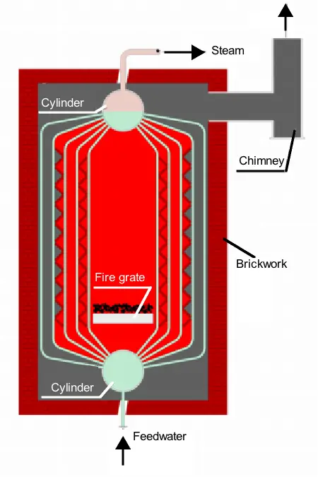
Steam Boiler 3 english
Image – Diagram of a water-tube boiler;
Image Credit – Wikipedia

Why does boiler pressure drop?

Boiler pressure drop means dropping the amount of water which is circulating in the heating system or the boiler system.

The reason behind the pressure drop in the system of the boiler is listed below,

  • Leakage is present in the boiler
  • Leakage is present in the system of the boiler
  • Broken parts of the boiler
  • Fault is present in the pressure relief valve
  • Damaged expansion vessel
  • Bled of the radiators

Leakage is present in the boiler:-

If leakage is present in the boiler then the pressure dropping appear. Leak can be appear in various parts of the boiler such as joints of the rings, automotive air vents, diverter valves and also in the washer for this reason the heat exchanger also can be defected. Bigger size leak can’t be miss, boiler will drop out from the bottom section but smaller size leak sometimes can be neglected because the dripping of water can be end up another part of the boiler.

 Leakage is present in the system of the boiler:-

If leakage is present in the pipe system of the boiler then this leakage also can be causes pressure dropping of the boiler or heating system. When leakage is appear a quick investigation is needed to find the particular place from where the water is dripping. Mainly around the bends and joints leak can be occurring.

Broken parts of the boiler:-

The reason behind the pressure drop in the system of the boiler is broken parts are present in the boiler. If excess amount of pressure is dropping then we need to understand that some parts should be broke and it can be identified by the monitor of the boiler.

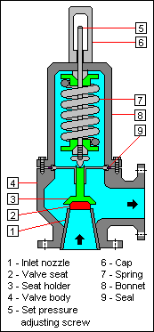
Fault is present in the pressure relief valve:-

The purpose of using pressure relief valve is when the excess amount of pressure above the 3 bar is crosses that time the pressure inside the boiler exist by the pressure relief internal valve and pressure relief external valve. But when the leakage is present in the pressure relief valve the pressure could not release in a proper way and pressure is dropping in the system.

does boiler pressure drop
Image – Schematic diagram of a conventional spring-loaded pressure relief valve;
Image Credit – Wikipedia

Damaged expansion vessel:-

If defection in present in the expansion vessel in that case the pressure will be arise up to 3 bars when boiler heat up. Expanded water could not get enough space to flow as a result from the pressure relief internal valve and pressure relief external valve the excess amount of pressure is exit and pressure drop is appear in the boiling system or heating system.

Bled of the radiators:-

Another reason behind the pressure drop in the system of the boiler is bled of the radiators. Identification and fixing the issue of bled of the radiators is not too complicated.

How often should boiler pressure drop?

When the system of the boiler or the system of heating is cold, the pressure should be stand in between 1 bar to 1.5 bars. If the amount of pressure drop is lower than the ideal one (near about 0.5 bars) in that case water shortage is appear in the system and the whole system need a replacement.

If the pressure is continuously drooping from the system of the boiler or system of the heating then we should to follow some steps they are listed below,

  1. In the first step of the process the boiler should be shut off and make sure that the boiler should be fully cooled down.
  2. In the next step the both edges of the filling loop double checking is necessary thus they should securely connect.
  3. Open the both internal valve and external valve to deliver cold substance water into the system of the boiler or system of the heating.
  4. Wait until the range of the pressure gauge comes to the read point of 1.5 bars.
  5. Close the both internal valve and external valve step by step.
  6. If boiler back required then reset button is pressed.
  7. In the final step the both edges of the filling loop unfurl and remove.

Does boiler pressure drop in summer?

Yes, during the season of summer boiler pressure drop is happened. Dropping the pressure is a very common and normal matter almost every time pressure is drop due to many reasons.

In the system of the boiler the pressure can be drop for the leakage of the boiler any others parts of the boiler if some fault is present. Mainly during the water circulation of the system water is expand that time water could not enough space to circulate and relief valve is open to normalize the inside condition of the boiler at that particular time pressure is also dropped.

Does boiler pressure drop in winter?

Yes, during the season of winter boiler pressure drop condition can be observed. Dropping the pressure is a very common thing almost every time pressure is drop due to many reasons.

The reason behind the pressure drop in the system of the boiler is broken parts are present in the boiler. If excess amount of pressure is dropping then we need to understand that some parts should be broke and it can be identified by the monitor of the boiler, we need to take help of experts.

Does boiler pressure drop when heating off?

Yes, in the system of the boiler pressure is drop when heating is off. There are two main problems that typically cause a loss of pressure – water escaping somewhere in the system or a failure of the expansion valve and resulting damage to the pressure relief valve.

Why does boiler pressure drop when heating is on?

The reason behind the pressure drop in the boiler when heating is on are listed below,

  • Leakage is present in the boiler
  • Leakage is present in the system of the boiler
  • Broken parts of the boiler
  • Fault is present in the pressure relief valve
  • Damaged expansion vessel
  • Leakage is present in the boiler

Does boiler pressure drops when running hot water?

Yes, in the system of the boiler pressure is drop when hot water is running.

Why does boiler pressure drop overnight?

The most common reason for dropping the pressure overnight is releasing the water or air from the radiator when it is bleeding. The issue of the bled of radiator is not a major problem with little bit awareness and repairing the problem easily can be fix.

The other reason of the pressure drop in the system of the boiler is listed below,

  1. Leakage is present in the boiler
  2. Leakage is present in the system of the boiler
  3. Broken parts of the boiler
  4. Fault is present in the pressure relief valve
  5. Damaged expansion vessel

Why does boiler pressure drop every day?

The most common reason for dropping the pressure everyday is releasing the water or air from the radiator when it is bleeding. The issue of the bled of radiator is not a major problem with little bit awareness and repairing the problem easily can be fix.

If leakage is present in the pipe system of the boiler then this leakage also can be causes in an everyday manner pressure dropping of the boiler or heating system. When leakage is appear a quick investigation is needed to find the particular place from where the water is dripping.

If by a small investigation the leakage of the system can be identify then it’s okay but if not then skilled person required to fix the problem. Mainly around the bends and joints leak can be occurring.

The symbol for leak present in the system are listed below,

  • Mould appearing
  • Bulging or swelling of ceilings or floor boards.
  • Peeling paint rust spot

If the pressure of the boiler is low that we can measure with the help of pressure gauge or discussion with boiler manual.

The leaks are checked in the surrounding of the radiators connection of the pipes. Water stain and discoloration of the pipe is the sign if the leakage in the pipes.

A expert hand needed if required to recover internal parts fault.

21 Facts on Plug Weld: The Complete Beginner’s Guide

plug weld

In this article, the subject “Plug Weld” with 21 Facts on Plug Weld will be discussing in a brief manner. Plug weld is also known as, Rosette weld.

The welding process of the plug is done when two metals are fused by the welds areas in younger circular holes. The plug weld method is done by the overlapping two metals. When two are overlapped in the top metal hole is created for deposition of the weld.

When spot weld cannot be performing in the metal in that case plug weld is done which can be occurring fairly at every moment.

What is plug weld?

The meaning of the plug weld is a stopper of a gap. Plug welds actually a round shaped weld. In the weld system of the plug two metals are overlapping with each other and a gap is present in one of the metal. The weld is credited in the gap to stop it. The wall of the gaps are remains straight but it is not required. The wall of the gaps can be bended too.

Plug weld symbol:

The symbol of the plug weld is a rectangle with a symbol of diameter situated to the side of the left of the weld symbol same as the number is combined with the symbol of diameter.

Plug Weld
Image – Plug Weld

Plug welds uses:

At modern engineering fields the plug weld are widely used in various sectors. A welder can easily handle the plug weld with a little exercise and learning. In the automotive sectors and aerospace plug weld is used.

Automotive sector:-

In the automotive sector where heavy machines are need to weld in that case the equipment of spot weld cannot be installed to perform for the insufficient space but as an alternative the plug weld easily can be installed there. The gaps of the machines can be easily welded by the plug weld. The strength of the plug weld is stronger than the spot weld.

Aerospace:-

To fill in the damages in the gaps on the components of the aerospace the plug weld is use. In the gaps of the exit cases and fans preciously filled without scrapping the whole system.

When to use plug weld?

In the sector of the automotive and aerospace where more precious and cleaned welding is require in that case plug weld is used instead of spot welding.

In automotive fields heavy machines are need to weld in that case the equipment of spot weld cannot be installed to perform for the insufficient space but as an alternative the plug weld easily can be installed there.

In the aerospace to filling the holes more accurate welding process is needed in that case plug weld is also used. Accuracy and strength of the plug is more than the spot weld.

Why to use plug weld?

Plug welds are circular shaped welds which are mainly used to corroborate two faces of the metal together by a small size space in one of the faces. In the field of the automotive plug welding is widely used as a substitute of spot welding when the equipment of the spot welding is gets insufficient area to operate.

The strength of the plug welding is more compare to the spot welding.

Plug weld hole size:

The minimum size of the diameter of the hole particularly for the plug should not be less than, the thickness of the part mixed with it plus 5/16(8 mm) ideally rounded to the following higher unaccompanied 1/16″. The highest width shall is same to the minimum width plus 1/8″(3 mm) or 2-1/4 times the thickness of the part, whichever is greater.

Plug weld joint:

In the industrial field with the help of the plug weld in generally five types of joints can be made, they are listed below,

  • Edge joint
  • Corner joint
  • Butt joint
  • Lap joint
  • Tee joint

Edge joint:-

Edge joint is not applicable for pressure and stress application. Edge joint can be explained as, when two edges of two different parts are joint with each other. The edge joint is appropriate for when the two sheets are adjacent and almost stays at parallel surface at the spot of the welding.

The different types of Edge joints are listed below,

  1. U groove weld
  2. V groove weld
  3. J groove weld
  4. Bevel groove weld
  5. Corner flange weld
  6. Square groove weld

Corner joint:-

Corner joint can be explained as; when two parts corners are situated to form a joint at the angle of right. With the two parts joining the shaped form like L.

The different types of Corner joints are listed below,

  1. Spot weld
  2. Bevel groove weld
  3. U groove weld
  4. V groove weld
  5. J groove weld
  6. Square groove weld
  7. Fillet weld
  8. Corner flange weld
  9. Edge weld
  10. Flare V groove weld

Butt joint:-

The easiest and simplest joint which is can make by the plug weld is butt joint. The butt joint is created by situated the two parts end section together. The two parts in the butt joint place in the same surface or one after another.

The different types of the Butt joint are listed below,

  1. Bevel groove weld
  2. U groove weld
  3. V groove weld
  4. J groove weld
  5. Square groove weld
  6. Flare bevel groove weld
  7. Flare V groove weld

Lap joint:-

With the help of lap joint mainly two different thickness metals can be joint with each other. Lap joint can be define as, when two parts are overlapping with each other. Lap joint can be double sided or single sided.

The different types of the Lap joint are listed below,

  1. Bevel groove weld
  2. J groove weld
  3. Slot weld
  4. Fillet weld
  5. Spot weld
  6. Flare bevel groove weld
  7. Plug weld

Tee joint:-

Tee joint can be explained as, when the two different parts are intersecting with each other at the angle of right and one part is lie at the other at the centre. Tee joint form like T letter.

The different types of the Tee joint are listed below,

  1. Plug weld
  2. Bevel weld
  3. Slot weld
  4. Fillet weld
  5. Melt through weld
  6. Flare bevel weld
  7. J groove weld

Plug welding thick steel:

The process done with the thick metal in plug welding is listed below,

  • Cleaning the thick steel
  • Marking on the top the thick steel
  • Holes are created on the top of the thick steel
  • Place the thick steels together
  • Placed the welding

Plug welds design and strength:

The strength of the plug weld is more than comparative to the spot weld. With the plug weld thick metals can be work. The design of the plug weld is not applicable for high force and stress.­­­­­­

How to calculate plug weld strength?

The process for calculating the strength of the plug weld is listed below,

  • The weld size and the weld strength are multiply with each other.
  • The highest permissible tensile strength is dividing with the above product.
  • The resultant should be multiply with the value of 0.77 to get the joint of the weld length.

Plug welding procedure:

The process of the plug welding is done in some steps. The steps are describe in below,

  • Step – 1: Cleaning the metal
  • Step – 2: Marking on the top metal
  • Step – 3: Holes are created on the top metal
  • Step – 4: Place the top metal and base metal together
  • Step – 5: Placed the welding

Step – 1: Cleaning the metal:-

In the beginning of the plug welding at first the pre preparation is done. In this step the base metal need to clean up thus any dirt or impurities cannot takes place during the welding process and also cleaning is important after the welding  method no defect is present. Safety is very important while welding process. Welding gloves, welding helmet, should be wear by the welder to prevent accident. At last welding burn is not desire during the plug welding process.

Step – 2: Marking on the top metal:-

In the next step of the plug welding marking is done on the top section of the base metal. If multiple plugs welding are done in the base metal in that case requires to be spaced out on a level.

Step – 3: Holes are created on the top metal:-

After marking, the holes are created in which places where the plug welding will be created. In the various ways hole can be done in the base metal among them drilling is most common process chosen by the welders to create holes.

Step – 4: Place the top metal and base metal together:-

After completingmarking the metal should be placed together thus they cannot move during the process. A plug weld clamp is use to clamp the metals at one place.

Step – 5: Placed the welding:-

At the last of the process weld is placed. When the welding is placed the most important criteria need to remember that, the process should be start on the external side along the points of the edges, the way of the working will be towards the middle. The strength of the metal will be increases and chances of the defect will be decreases by this process and also the temperature of the base metal is rise up to the temperature of the top metal.

Can plug welds be used in tension?

No, plug welds cannot be used in tension.

The dimensions which are applied for the symbol of the plug weld are listed below,

  1. Depth of filling
  2. Size
  3. Angle of counter stroke
  4. Number of the welds
  5. Spacing of the welds

How to plug weld sheet metal?

The process of the plug welding in the sheet metal is done in some steps. The steps are describe in below,

  • Cleaning the sheet metal
  • Marking on the top the sheet metal
  • Holes are created on the top of the sheet metal
  • Place the sheet metal together
  • Placed the welding

Cleaning the sheet metal:-

In the beginning of the plug welding at first the pre preparation is done. In this step the sheet metal need to clean up thus any dirt or impurities cannot takes place during the welding process and also cleaning is important before the welding  method no defect is present.

Marking on the top the sheet metal:-

In the next step of the plug welding marking is done on the top section of the sheet metal. If multiple plugs welding are done in the sheet metal in that case requires to be spaced out on a level.

Holes are created on the top of the sheet metal:-

After marking, the holes are created in which places where the plug welding will be created. In the various ways hole can be done in the base metal among them drilling is most common process chosen by the welders to create holes. Mostly 8 mm – 10 mm hole is doing. The hole diameter depend on the flange width and the distance keep between the holes are near about 25 mm.

Place the sheet metal together:-

After completingmarking the metal should be placed together thus they cannot move during the process. A plug weld clamp is use to clamp the metals at one place.

Placed the welding:-

At the last of the process weld is placed. When the welding is placed the most important criteria need to remember that, the process should be start on the external side along the points of the edges, the way of the working will be towards the middle. The strength of the metal will be increases and chances of the defect will be decreases by this process and also the temperature of the base metal is rise up to the temperature of the top metal.

Plug weld vs. slot weld:

The major differences in between the plug weld and slot weld are describe below,

Plug weldSlot weld
A weld made in a circular hole in one member of a joint fusing that member to another member. A fillet-welded hole is not to be construed as conforming to this definition.A slot weld joins the surface of a piece of material to another piece through an elongated hole. The hole can be open at one end and can be partially or completely filled with weld material.
The shape of the plug weld can be identified with the help of diameter.The shape of the slot weld can be identified with the help of the both length and diameter.
Application of the plug weld is,
1. Manufacturing the body of the automotive 2. Repairing the body of the automotive
3. Welding tubes inside a pipe
4. To join different thickness metal
Application of the slot weld is,
1. Dispatch the shear force in lap joints
2. Stopping buckling in overlapped portions.

Puddle weld vs. plug weld:

The major differences in between the plug weld and puddle weld are describe below,

Plug weldPuddle weld
The welding process of the plug is done when two metals are fused by the welds areas in younger circular holes.A type of plug welds for joining two sheets of light-gauge material; a hole, burned in the upper sheet, is filled with a puddle of weld metal to fuse the upper sheet to the lower.
Thick material can work with the plug weld.Thick material could not work with puddle weld.

Plug weld vs. spot weld:

The major differences in between the plug weld and spot weld are describe below,

Plug weldSpot weld
The welding process of the plug is done when two metals are fused by the welds areas in younger circular holes. The plug weld method is done by the overlapping two metals. When two are overlapped in the top metal hole is created for deposition of the weld.  Spot welding process can be explain as, welding together two or more than two metals with the help of heat and pressure into the area of the weld from an electric current.
The strength of the plug weld is more than the spot weld.The strength for the spot weld is comparative less than the plug weld.
Technical cost is low.Technical cost is high.
Accuracy of the plug weld is more.Accuracy of the spot weld is less comparative to the spot weld.
For the repairing of the automotive body panel plug weld is used.For the assembly of the automotive body panel spot weld is used.

Necessity of space in plug socket weld:

With the help of space between the two plates in the plug socket weld the quality of the weld can be easily determine. If gap is present in between two plates then it’s called good plug socket weld and if gap is not present in between two plates then it’s called bad plug socket weld.

The space of the plug socket weld is used to minimize the crakes while the plates are gets warmer to absorb the excess amount of temperature during the welding process.

Conclusion:

If skilled welder with a little learning can work with plug weld then it is very advanced and suitable process to weld. The strength of the plug weld is good enough to weld.

23 Facts on Hoop Stress: The Complete Beginner’s Guide

386px Circumferential stress.svg 300x242 1

In this article, the topic, “hoop stress” with 23 Facts on Hoop Stress will be discussed in a brief portion. In the outer radius or inner radius portion of a tube hoop stress is remains maximum.

The calculation of the hoop stress is estimate the stress which is acted on a thin circumference pressure vessel. For estimate the hoop stress in a sphere body in some steps. The steps are listed below,

  • The internal diameter of the yard and internal pressure should be multiply at the beginning of the process.
  • In the next step the resultant should be divided four times with the thickness of the shell.
  • In final stage divide the resultant with the joint efficiency.
hoop stress
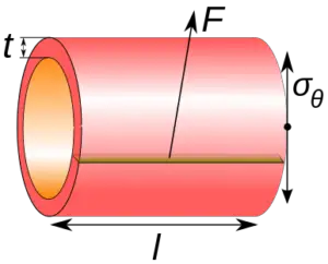
Image – Components of hoop stress; Image Credit – Wikipedia

What is hoop stress?

The hoop stress can be explain as, the stress which is produce for the pressure gradient around the bounds of a tube. The maximum amount of hoop stress is appearing in the outer radius and inner radius of the tube. The hoop stress depends upon the way of the pressure gradient.

The reason behind the hoop stress is, when a cylinder is under the internal pressure is two times of the longitudinal stress. In a tube the joints of longitudinal produced stress is two times more than the circumferential joints. If pressure is applied in a tube uniformly then the hoop stress in the length of the pipe will be uniform.

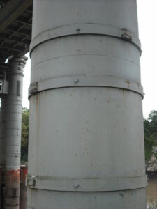
450px Wrought iron straps Chepstow Railway Bridge
Image – Cast iron pillar of Chepstow Railway Bridge, 1852. Pin-jointed wrought iron hoops (stronger in tension than cast iron) resist the hoop stresses; Image Credit – Wikipedia

What is hoop stress in pressure vessel?

The hoop stress in a pressure vessel is acted perpendicular to the direction to the axis. Hoop stresses are generally tensile. The hoop stress is appearing for resist the effect of the bursting from the application of pressure.

Mathematically can written for hoop stress in pressure vessel is,

σθ = P.Dm/2t

Where,

σθ = Hoop stress

P = Internal pressure of the pressure vessel

Dm= Mean diameter of the pressure vessel

t = Thickness of the wall of the pressure vessel

For thin walled pressure vessel the thickness will be assumed as one tenth of the radius of the vessel not more than of it.

In the system of the Inch – pound – second the unit for the internal pressure of the pressure vessel express as ponds – force per square inch, unit for Mean diameter of the pressure vessel is inches, unit for thickness of the wall of the pressure vessel inches and, In the system of the S.I. unit for the internal pressure of the pressure vessel express as Pascal, and unit for Mean diameter of the pressure vessel is meter, unit for thickness of the wall of the pressure vessel meter.

What is hoop stress in pipelines?

Hoop stress in pipelines can be explain as, the stress in a wall of a pipe operable circumferentially in a profile perpendicular to the axis of the longitudinal of the tube and rose by the tension of the fluid substance in the pipe.

The hoop stress actually is a function which is go about to tension the pipe separately in a direction of the circumferential with the tension being created on the wall of the pipe by the internal pressure of the pipe by natural gas or other fluid.

The hoop stress increases the pipe’s diameter, whereas the longitudinal stress increases with the pipe’s length. The hoop stress generated when a cylinder is under internal pressure is twice that of the longitudinal stress.

Hoop stress formula:

The formula of the Barlow’s is used for estimate the hoop stress for the wall section of the pipe.

The formula for the hoop stress can be written as,

 σθ = P.D/2t

Where,

σθ = Hoop stress

P = Internal pressure of the pipe

D = Diameter of the pipe

t = Thickness of the pipe

In S.I. unit, P (the internal pressure of pipe) expresses as Pascal, and unit for D (diameter of the pipe) is meter, unit for t (thickness of the wall of the pipe) is meter. In the system of the Inch – pound – second unit, P (the internal pressure of pipe) expresses as ponds – force per square inch, and unit for D (diameter of the pipe) is inches, unit for t (thickness of the wall of the pipe) is inches.

Hoop stress formula for thick cylinder:

Tangential stress and radial stress in a cylinder with thick walled tubes or cylinder with internal pressure, external pressure with closed ends.

Hoop stress formula in the case of thick cylinder three sections. The three sections are listed below,

  • Hoop stress in the direction of the axial
  • Hoop stress in the direction of the circumferential
  • Hoop stress in the direction of the radial

Hoop stress in the direction of the axial:-

The hoop stress in the direction of the axial at a particular point in the wall of the cylinder or tube can be written as,

gif

Where,

σa= Hoop stress in the direction of the axial and unit is MPa, psi.

pi = Internal pressure for the cylinder or tube and unit is MPa, psi.

ri = Internal radius for the cylinder or tube and unit is mm, in.

po = External pressure for the cylinder or tube and unit is MPa, psi.

ro = External radius for the cylinder or tube and unit is mm, in.

Hoop stress in the direction of the circumferential:-

The hoop stress in the direction of the circumferential at a particular point in the wall of the cylinder or tube can be written as,

gif

Where,

σc = The hoop stress in the direction of the circumferential and unit is MPa, psi.

pi = Internal pressure for the cylinder or tube and unit is MPa, psi.

ri = Internal radius for the cylinder or tube and unit is mm, in.

po = External pressure for the cylinder or tube and unit is MPa, psi.

ro = External radius for the cylinder or tube and unit is mm, in.

r = Radius for the cylinder or tube and unit is mm, in. (ri < r < ro)

Maximum hoop stress for the cylinder or tube is, ri = r

Hoop stress in the direction of the radial:-

The hoop stress in the direction of the radial at a particular point in the wall of the cylinder or tube can be written as,

gif

Where,

σr = The hoop stress in the direction of the radial circumferential and unit is MPa, psi.

pi = Internal pressure for the cylinder or tube and unit is MPa, psi.

ri= Internal radius for the cylinder or tube and unit is mm, in.

po = External pressure for the cylinder or tube and unit is MPa, psi.

ro = External radius for the cylinder or tube and unit is mm, in.

Hoop stress formula for pipe:

The formula of the Barlow’s is used for estimate the hoop stress for the wall section of the pipe.

The formula for the hoop stress can be written as,

σθ = P.D/2t}

Where,

σθ] = Hoop stress

P = Internal pressure of the pipe

D = Diameter of the pipe

t = Thickness of the pipe

In S.I. unit, P (the internal pressure of pipe) expresses as Pascal, and unit for D (diameter of the pipe) is meter, unit for t (thickness of the wall of the pipe) is meter.

In the system of the Inch – pound – second unit, P (the internal pressure of pipe) expresses as ponds – force per square inch, and unit for D (diameter of the pipe) is inches, unit for t (thickness of the wall of the pipe) is inches.

Hoop stress formula for sphere:

The hoop stress formula for the sphere is discussed in below section,

  • Hoop stress formula for sphere in thin walled section
  • Hoop stress formula for sphere in thick walled section
  • Hoop stress formula for sphere in thick walled section (Only for internal pressure)
  • Hoop stress formula for sphere in thick walled section (Only for external pressure)

Hoop stress formula for sphere in thin walled section:-

Thin walled portions of a spherical tube or cylinder where both internal pressure and external pressure acted can be express as,

Pr/2t

Hoop stress formula for sphere in thick walled section:-

Thick walled portions of a spherical tube and cylinder where both internal pressure and external pressure acted can be express as,

gif

Hoop stress formula for sphere in thick walled section (Only for internal pressure):-

Thick walled portions of a tube and cylinder where only internal pressure acted can be express as,

gif

Hoop stress formula for sphere in thick walled section (Only for external pressure):-

Thick walled portions of a tube and cylinder where only external pressure acted can be express as,

gif

Where,

σh = The hoop stress and unit is MPa, psi.

P = Pressure under consideration and unit is MPa, psi.

pi = Internal pressure for the cylinder or tube and unit is MPa, psi.

ri = Internal radius for the cylinder or tube and unit is mm, in.

po = External pressure for the cylinder or tube and unit is MPa, psi.

ro = External radius for the cylinder or tube and unit is mm, in.

r = Radius for the cylinder or tube and unit is mm, in.

t = Wall thickness for the cylinder or tube and unit is mm, in.

Hoop stress formula for conical cylinder:

Hoop stress formula for conical cylinder can be express for two conditions. The conditions are listed below,

  • When the liquid substance is stays at the surface of below y (y < d)
  • When the liquid substance is stays at the surface of above y or equal to y (y >d, y = d)

Case: 1: When the liquid substance is stays at the surface of below y (y < d):-

Meridional stress:

σ1 = δytanα/2tcosα (d-2y/3)

Hoop stress or circumferential stress:

gif

Radial Displacement of circumference :

gif

Change in the height of dimension y:

gif

Turning of a meridian out of its unloaded condition:

gif

Case: 2: When the liquid substance is stays at the surface of above y or equal to y (y >d, y = d):-

Meridional stress:

gif

Hoop stress or circumferential stress:

σ2 = 0

Radial Displacement of circumference:

gif

Change in the height of dimension y:

gif

Turning of a meridian out of its unloaded condition:

gif

Where,

σ1 = Hoop stress and unit is lbs/in2

σ2 = Hoop stress and unit is lbs/in2

E = Modulus of Elasticity and unit is lbs/in2

ψ = Turning of a meridian out of its unloaded condition.

v = Poisson’s ratio and it is unit less.

Δ= Liquid density and unit is lbs/in3

d = Liquid fill level and unit is in.

t = Wall thickness unit is in.

α = Angle and unit degree.

y = Pointing a level of a cone and unit is in.

Hoop stress formula derivation:

Another term for the cylindrical tube is pressure vessel. In various fields of engineering the pressure vessels are used such as, Boilers, LPG cylinders, Air recover tanks and many more.

Derivation of the hoop stress formula:-

Cylindrical shell bursting will take place if force due to internal fluid pressure will be more than the resisting force due to circumferential stress or hoop stress developed in the wall of the cylindrical shell.

Let consider the terms which explaining the expression for hoop stress or circumferential stress which is produce in the cylindrical tube’s wall.

P = Internal fluid pressure of the cylindrical tube

t = Thickness for the cylindrical tube

L= Length for the cylindrical tube

d = Internal diameter for the thin cylindrical tube

σH = Hoop stress or circumferential stress which is produce in the cylindrical tube’s wall

Force produce for the internal fluid pressure = Area where the fluid pressure is working * Internal fluid pressure of the cylindrical tube

Force produce for the internal fluid pressure = (d x L) x P

Force produce for the internal fluid pressure = P x d x L …….eqn (1)

Resulting force for the reason of hoop stress or circumferential stress = σH x 2Lt …….eqn (2)

From the …….eqn (1) and eqn (2) we can write,

Force produce for the internal fluid pressure = Resulting force for the reason of hoop stress or circumferential stress

P x d x L = σH x 2Lt

σH= Pd/2t

How to calculate hoop stress?

For calculating the hoop stress for a sphere body the steps are listed below,

  • The internal diameter of the yard and internal pressure should be multiply at the beginning of the process.
  • In the next step the resultant should be divided four times with the thickness of the shell.
  • In final stage divide the resultant with the joint efficiency.

How to calculate hoop stress in pipe?

For calculating the hoop stress just need to multiply the internal diameter (mm) of the pipe with internal pressure (MPa) of the pipe and then the value need to divided with the thickness (mm) of the pipe with 2.

Formula for estimate the hoop stress in a pipe is,

Hoop stress = Internal diameter x Internal pressure/2 x Thickness

Mathematically hoop stress can be written as,

σθ= P.D/2t

Where,

σθ = Hoop stress

P = Internal pressure

D = Diameter of the pipe

t = Thickness of the pipe

How to calculate hoop stress of a cylinder?

Hoop stress can be explained as; the mean volume of force is employed in per unit place. The hoop stress is the capacity is applied circumferentially in both ways on every particle in the wall of the cylinder.

Formula for estimate the hoop stress of a cylinder is,

Hoop stress = Internal diameter x Internal pressure/2 x Thickness

Mathematically hoop stress can be written as,

σθ = P.D/2t

Where,

σθ = Hoop stress in the direction of the both and unit is MPa, psi.

P = Internal pressure of the pipe and unit is MPa, psi.

D = Diameter of the pipe and unit is mm, in.

t = Thickness of the pipe and unit is mm, in.

Hoop stress vs. radial stress:

The major difference between hoop stress and radial stress are describe in below section,

Hoop stress Radial stress
Hoop stress can be explained as; the mean volume of force is employed in per unit place. The hoop stress is the capacity is applied circumferentially in both ways on every particle in the wall of the cylinder.   Radial stress can be explained as; stress is in the direction of or away from the central axis of a component.
Mathematically hoop stress can be written as,
σh= P.D/2t
Where,
P = Internal pressure of the pipe and unit is MPa, psi.
D = Diameter of the pipe and unit is mm, in.
t = Thickness of the pipe and unit is mm, in.  
Mathematically radial stress can be written as,
gif Where,
σr= The radial stress and unit is MPa, psi.
pi = Internal pressure for the cylinder or tube and unit is MPa, psi.
ri = Internal radius for the cylinder or tube and unit is mm, in.
po = External pressure for the cylinder or tube and unit is MPa, psi.
ro = External radius for the cylinder or tube and unit is mm, in.
r = Radius for the cylinder or tube and unit is mm, in.
 
The hoop stress usually much larger for pressure vessels, and so for thin-walled instances, radial stress is usually neglected. The radial stress for a thick-walled cylinder is equal and opposite of the gauge pressure on the inside surface, and zero on the outside surface.

Hoop stress vs. axial stress:

The major difference between hoop stress and axial stress are describe in below section,

Hoop stress Axial stress
The hoop stress, or tangential stress, is the stress around the circumference of the pipe due to a pressure gradient. The maximum hoop stress always occurs at the inner radius or the outer radius depending on the direction of the pressure gradient. Axial stress describes the amount of force per unit of cross-sectional area that acts in the lengthwise direction of a beam or axle. Axial stress can cause a member to compress, buckle, elongate or fail.
Mathematically hoop stress can be written as, σh= P.D/2t Mathematically axial stress can be written as,
σa = F/A= Pd2/(d + 2t)2 – d2 
Hoop stress is not a shear stress. Axial stress is a shear stress.

Hoop stress vs. tangential stress:

The major difference between hoop stress and tangential stress are describe in below section,

Hoop stressTangential stressThe hoop stress in a pressure vessel is acted perpendicular to the direction to the axis. Hoop stresses are generally tensile. The hoop stress is appearing for resist the effect of the bursting from the application of pressure.   When the direction of the deforming force or external force is parallel to the cross-sectional area, the stress experienced by the object is called tangential stress.
Hoop stress is not a shear stress. Tangential stress is a shear stress.

Hoop stress vs. yield strength:

The major difference between hoop stress and yield strength are describe in below section,

Hoop stress Yield strength
Hoop Stress define as, the pipe material stress tangential to the pipe. In a properly supported round pipe containing a fluid under pressure the largest tensile stress is the hoop stress.   Yield Stress defines as, yield strength or yield stress is the material property defined as the stress at which a material begins to deform plastically whereas yield point is the point where nonlinear (elastic + plastic) deformation begins.  

Is hoop stress shear stress?

No, hoop stress or circumference stress is not a shear stress. In the theory of pressure vessel, any given element of the wall is evaluated in a tri-axial stress system, with the three principal stresses being hoop, longitudinal, and radial. Therefore, by definition, there exist no shear stresses on the transverse, tangential, or radial planes.

Is hoop stress tensile?

Hoop stress can be explained as; the stress is developed along the circumference of the tube when pressure is acted.

Yes, hoop stress is tensile and for this reason wrought iron is added to various materials and has better tensile strength compare to cast iron. Hoop stress is works perpendicularly to the direction of the axial. Hoop stresses are tensile, and developed to defend the effect of the bursting that appears from the movement of pressure.

Is hoop stress a principal stress?

Yes, hoop stress is the principal stresses. To estimate the longitudinal stress need to create a cut across the cylinder similar to analyzing the spherical pressure vessel. The form of failure in tubes is ruled by the magnitude of stresses in the tube. 

If there is a failure is done by the fracture, that means the hoop stress is the key of principle stress, and there are no other external load is present.

Is hoop stress normal stress?

Yes, hoop stress or circumferential stress is a normal stress in the direction of the tangential. Stress is termed as Normal stress when the direction of the deforming force is perpendicular to the cross-sectional area of the body. The length of the wire or the volume of the body changes stress will be at normal.

How to reduce hoop stress?

The method is to reducing the hoop stress is control a strong wire made with steel under tension through the walls of the cylinder to shrink one cylinder over another.

The most efficient method is to apply double cold expansion with high interference along with axial compression with strain equal to 0.5%. This technique helps to reduce absolute value of hoop residual stresses by 58%, and decrease radial stresses by 75%.

Conclusion:

  • A normal stress in tangential direction horizon of the cylinder surface.
  • Hoop stress also called as, Circumferential stress.
  • Hoop stress acts along φ.