Dioptric Power: A Comprehensive Guide for Science Students

dioptric power

Dioptric power is a crucial concept in the fields of optometry and ophthalmology, representing the optical power of a lens or curved mirror. This unit of measurement is essential for characterizing the refractive state of the eye and prescribing corrective lenses. In this comprehensive guide, we will delve into the intricacies of dioptric power, providing a wealth of technical details and practical applications for science students.

Understanding Dioptric Power

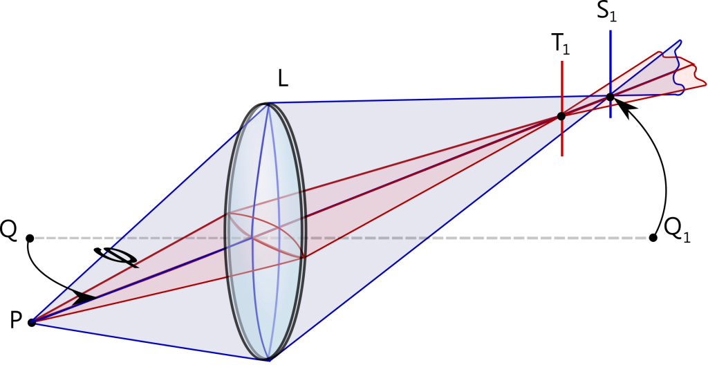
Dioptric power, also known as optical power, is defined as the reciprocal of the focal length of a lens or curved mirror, measured in meters. The formula for dioptric power (D) is:

D = 1 / f

Where:
– D is the dioptric power, measured in diopters (D)
– f is the focal length, measured in meters (m)

The dioptric power of a lens or mirror represents the ability to converge or diverge light rays, which is crucial for the proper functioning of the human eye and the design of optical devices.

Dioptric Demand of Near-Work Tasks
dioptric power

Researchers have objectively quantified the dioptric demand of various near-work tasks, such as reading print and using hand-held devices. The results of these studies provide valuable insights into the optical requirements for different visual activities.

Reading Print

In a study on near-work tasks and dioptric demand, researchers found that reading print had a dioptric demand of 2.64 D (95% CI 0.48 D to 2.81 D). This means that the eye requires an optical power of 2.64 diopters to focus light on the retina effectively while reading printed material.

Using Hand-Held Devices

The same study revealed that using hand-held devices, such as smartphones and tablets, had a dioptric demand of 3.00 D (95% CI 2.84 D to 3.17 D). This higher dioptric demand is due to the closer working distance and smaller visual targets associated with these devices.

These findings highlight the importance of understanding dioptric power in the context of visual tasks, as it can inform the design of corrective lenses and the management of visual fatigue and eye strain.

Evaluating Refractive Data and Dioptric Power

Researchers have reviewed various methods for evaluating refractive data and dioptric power. These methods are essential for accurately analyzing and comparing samples of dioptric power.

Sphero-Cylindrical Transposition

One of the key considerations in evaluating refractive data is the need for a system of analysis that allows for invariance of power under sphero-cylindrical transposition. This means that the dioptric power should be independent of the specific representation of the refractive error (e.g., sphere, cylinder, and axis).

Mathematical Operations

Researchers have described methods for calculating squares of power, performing mathematical operations, and testing samples for variance and departure from normality. These techniques are crucial for ensuring the reliability and validity of dioptric power measurements.

Statistical Analysis

Appropriate statistical analysis methods, such as testing for variance and normality, are essential for comparing dioptric power data across different samples or populations. This allows researchers and clinicians to draw meaningful conclusions from the data and make informed decisions.

Corneal Topography and Dioptric Power

Corneal topography is another area where dioptric power measurements are crucial. Corneal topography measures the curvature and shape of the cornea, which can be converted to dioptric power measurements.

Manual Keratometry

Early quantitative measurements of corneal curvature came from manual keratometry, which measured the radius of curvature and subsequently the dioptric power of the cornea along two principal meridians. However, this method was limited to a fixed chord of only 2mm or 3mm within the central optic zone of the cornea.

Placido Disc Topographers

Newer technologies, such as Placido disc topographers, can measure up to or including the limbus in a single capture, providing a much more accurate representation of corneal shape than keratometry. These topographers use sophisticated algorithms to calculate curvature and power data relative to the optical axis line of reference between the topographer camera and the cornea or relative to points not centered on the optical axis.

Limitations and Distortions

However, distortions in the projected rings can still occur due to tear film dryness, punctate keratopathy, corneal scarring, sutures, or abrupt curvature changes. These factors can affect the accuracy of the dioptric power measurements obtained through corneal topography.

Practical Applications of Dioptric Power

Dioptric power is a fundamental concept in various fields, including:

  1. Optometry and Ophthalmology: Dioptric power is used to characterize the refractive state of the eye and prescribe corrective lenses, such as eyeglasses and contact lenses.
  2. Optical Device Design: The dioptric power of lenses and mirrors is crucial in the design of optical devices, such as cameras, telescopes, and microscopes.
  3. Vision Research: Dioptric power measurements are used in vision research to study the visual system, including the effects of refractive errors, accommodation, and presbyopia.
  4. Corneal Refractive Surgery: Dioptric power measurements are essential in planning and evaluating the outcomes of corneal refractive surgeries, such as LASIK and PRK.
  5. Low Vision Rehabilitation: Dioptric power is considered in the selection and fitting of optical aids for individuals with low vision, such as magnifiers and telescopic devices.

Conclusion

Dioptric power is a critical concept in the fields of optometry and ophthalmology, with far-reaching applications in various scientific disciplines. This comprehensive guide has provided a wealth of technical details and practical applications related to dioptric power, equipping science students with a deep understanding of this fundamental topic. By mastering the concepts and methods presented here, students can enhance their knowledge and skills in the pursuit of their scientific endeavors.

References

  1. Objective Quantification and Topographic Dioptric Demand of Near Work Tasks. https://www.ncbi.nlm.nih.gov/pmc/articles/PMC9942781/
  2. Dioptric power and refractive behaviour: a review of methods. https://www.ncbi.nlm.nih.gov/pmc/articles/PMC8977790/
  3. Corneal Topography: Get to New Heights. https://www.reviewofcontactlenses.com/article/corneal-topography-get-to-new-heights
  4. Diopter (dpt) – T&M Atlantic. https://www.tmatlantic.com/encyclopedia/index.php?ELEMENT_ID=17551

The Comprehensive Guide to Autorefractor: A Detailed Exploration of its Measurements and Applications

autorefractor

Autorefractors are sophisticated devices used to precisely measure the refractive error of the eye, enabling eye care professionals to determine the optimal lens prescription for glasses or contact lenses. These instruments employ advanced optical and electronic technologies to provide a comprehensive analysis of the eye’s refractive properties, delivering a wealth of data that can be used to diagnose and treat a wide range of vision-related conditions.

Understanding the Autorefractor Printing Data

The printing data generated by an autorefractor typically includes the following key measurements:

Sphere (SPH) Measurement

The sphere measurement indicates the degree of nearsightedness (myopia) or farsightedness (hyperopia) in the eye. Negative values represent nearsightedness, while positive values indicate farsightedness. This measurement is crucial in determining the appropriate corrective lens power.

Cylinder (CYL) Measurement

The cylinder measurement quantifies the amount of astigmatism present in the eye. A cylinder value of zero indicates no astigmatism, while positive or negative values represent the degree of astigmatism. This information is essential for prescribing the correct cylindrical lens component.

Axis Measurement

The axis measurement specifies the orientation of the astigmatism, ranging from 0 to 180 degrees. This data, combined with the cylinder measurement, allows for the precise alignment of the corrective lens to address the eye’s unique astigmatic properties.

Corneal Curvature (K-Readings)

The autorefractor measures the curvature of the cornea, the clear outermost layer of the eye, which is a crucial factor in determining the proper fit of contact lenses and diagnosing conditions such as keratoconus. The printing data typically includes the following corneal curvature measurements:

  1. MM1 (K1 or Flat K): Measures the curvature of the cornea in the flattest meridian.
  2. MM2 (K2 or Steep K): Measures the curvature of the cornea in the steepest meridian.
  3. MM: The average of the flat and steep M-readings, used to determine the overall corneal curvature.
  4. A: Indicates the orientation of the corneal curvature, measured in degrees from 0 to 180.
  5. R1: The data of the cornea in the flattest meridian.
  6. R2: The data of the cornea in the steepest meridian.

Corneal Dioptric Power

This measurement is used to calculate the prescription for contact lenses or assess the refractive power of the cornea.

Corneal Astigmatism

Corneal astigmatism is the difference between the flat and steep K-readings, representing the amount of astigmatism present in the cornea.

Pupil Distance (PD) Measurement

The pupil distance measurement indicates the distance between the pupils of the eyes, measured in millimeters. This information is crucial for properly fitting eyeglasses.

Autorefractor Accuracy and Validity

autorefractor

Numerous studies have been conducted to evaluate the accuracy and validity of autorefractors in comparison to other methods of refractive error measurement.

In a study comparing three autorefractors (Topcon RM-A 6000, Nidek AR 800, and Nikon NR 5000) with a hand-held Retinomax (R) autorefractor in 276 subjects and 48 infants under cycloplegia, the hand-held autorefractor showed better accuracy, with an AUC of 0.747 at a 0.25 cut point value under cycloplegia. Precycloplegic regression analysis revealed a very weak positive correlation (R^2 = 0.064) with high statistical significance (P < 0.0001), while cycloplegic regression analysis improved (R^2 = 0.303), indicating a positive relationship between the autorefractor (AR) and dynamic refraction (DR) methods.

Another study on accommodation by autorefraction and dynamic refraction in children found that the autorefractor measured -0.17 D of accommodative effort per unit change in dynamic refraction before cycloplegia and +0.90 D after cycloplegia. The infrared autorefractor showed significantly lower mean lag of accommodation when the near accommodative response was tested by the DR and AR methods.

In a study on the validity of autorefractor-based screening for irregular astigmatism, the autorefractor demonstrated a sensitivity of 78.1% (95% CI 73.1, 83.1) and a specificity of 76.1% (95% CI 71.0, 81.3) in diagnosing irregular astigmatism compared to conventional topography. Interestingly, the study found that age group was statistically significantly positively associated with specificity (P<0.001) and negatively associated with sensitivity (P=0.006). Additionally, female gender (P=0.008) and left eyes (P=0.05) had statistically significantly higher specificities compared to males and right eyes.

Practical Applications of Autorefractor Data

The comprehensive data provided by an autorefractor can be invaluable in various applications, including:

  1. Eyeglass and Contact Lens Prescriptions: The sphere, cylinder, and axis measurements are essential for determining the appropriate corrective lens prescription for glasses or contact lenses.
  2. Corneal Health Assessment: The corneal curvature (K-readings) and corneal dioptric power measurements can help eye care professionals diagnose and monitor conditions such as keratoconus, which affects the shape and refractive properties of the cornea.
  3. Astigmatism Management: The cylinder and axis measurements are crucial for accurately prescribing and fitting corrective lenses to address astigmatism, ensuring optimal visual acuity.
  4. Screening for Irregular Astigmatism: Autorefractor-based screening can be a valuable tool for detecting irregular astigmatism, which may indicate underlying eye conditions or the need for further examination.
  5. Pediatric Vision Assessments: Autorefractors can be particularly useful in evaluating refractive errors and accommodative function in children, providing valuable insights for vision care and development.

Conclusion

The autorefractor is a sophisticated and indispensable tool in the field of vision care, providing a wealth of detailed and quantifiable data that can be used to diagnose, treat, and monitor a wide range of eye-related conditions. By understanding the various measurements and their practical applications, eye care professionals can make informed decisions, deliver personalized treatment plans, and ultimately improve the visual health and quality of life for their patients.

References

  1. Comparison of Autorefraction and Retinoscopy in Infants and Young Children
  2. Accommodation by Autorefraction and Dynamic Refraction in Children
  3. Validity of Autorefractor-Based Screening Method for Irregular Astigmatism
  4. How to Read the Printing Data of the Autorefractor

A Comprehensive Guide to Telescope Parts and Usage

steps to use a telescope parts of a telescope

Telescopes are powerful tools that allow us to explore the wonders of the universe, from distant galaxies to the intricate details of our solar system. To fully harness the capabilities of a telescope, it’s essential to understand its various components and how to use them effectively. In this comprehensive guide, we’ll delve into the key parts of a telescope and provide a step-by-step approach to using them for optimal observation.

Telescope Types: Unraveling the Differences

Telescopes come in three primary types, each with its own unique characteristics and advantages:

Refractor Telescopes

Refractor telescopes use lenses to gather and focus light. The key parameters to consider are:

Aperture: The diameter of the objective lens, typically measured in inches or millimeters. A larger aperture gathers more light, enabling the observation of fainter celestial objects.

Focal Length: The distance between the lens and the point where the light converges, usually measured in millimeters. This determines the telescope’s magnification power.

Reflector Telescopes

Reflector telescopes use mirrors to gather and focus light. The critical factors are:

Aperture: The diameter of the primary mirror, which determines the light-gathering capability.

Focal Length: The distance between the primary mirror and the point where the light converges.

Catadioptric Telescopes

Catadioptric telescopes combine lenses and mirrors to provide a compact, high-quality image. The relevant parameters are:

Aperture: The diameter of the primary mirror or lens.

Focal Length: The distance between the primary mirror or lens and the point where the light converges.

Understanding these telescope types and their key specifications will help you choose the right instrument for your observational needs.

Eyepieces: The Window to the Cosmos

steps to use a telescope parts of a telescope

Eyepieces are essential components that allow you to view the celestial objects captured by the telescope. The focal length of the eyepiece, combined with the telescope’s focal length, determines the magnification power.

Magnification = Telescope Focal Length / Eyepiece Focal Length

For example, a telescope with a 1000mm focal length and a 25mm eyepiece would have a magnification of 40x (1000mm / 25mm = 40).

Choosing the right eyepiece for your observational needs is crucial. A higher magnification may not always be better, as it can reduce the field of view and introduce image distortion. It’s generally recommended to start with a lower magnification eyepiece and gradually increase the power as needed.

Finderscope: Your Celestial Navigation Tool

The finderscope is a low-power telescope attached to the main telescope. It serves as a guide, helping you locate and center celestial objects in the main telescope’s field of view.

To align the finderscope, follow these steps:

  1. Identify a bright star, planet, or the Moon as your target.
  2. Use a 26mm eyepiece (or a similar focal length for a reflector telescope) in the main telescope.
  3. Adjust the finderscope’s adjustment screws until the target object is centered in the finderscope’s view.

This alignment process ensures that the finderscope and the main telescope are pointing at the same celestial object, making it easier to find and track your desired targets.

Telescope Mounts: Stability and Precision

Telescope mounts play a crucial role in providing stability and precision for your observations. There are two primary types of telescope mounts:

Alt-Azimuth Mounts

Alt-Azimuth mounts allow movement in two axes: altitude (up and down) and azimuth (left and right). These mounts are relatively simple to use and are well-suited for casual stargazing.

Altitude: The angle between the telescope and the horizon, typically measured in degrees.
Azimuth: The horizontal direction of the telescope, often measured in degrees from north.

Equatorial Mounts

Equatorial mounts are designed to compensate for Earth’s rotation, making it easier to track celestial objects as they appear to move across the sky. These mounts have two axes:

Right Ascension (RA): The celestial equivalent of longitude, measured in hours, minutes, and seconds.
Declination (Dec): The celestial equivalent of latitude, measured in degrees.

Equatorial mounts require more setup and adjustment, but they offer superior tracking capabilities, making them the preferred choice for astrophotography and serious observational work.

Telescope Accessories: Enhancing Your Observational Experience

In addition to the core telescope components, there are various accessories that can enhance your observational experience:

  1. Eyepiece Filters: These filters can improve contrast, reduce glare, and enhance the visibility of specific celestial features.
  2. Barlow Lenses: These accessories increase the effective focal length of the telescope, providing additional magnification without the need for a new eyepiece.
  3. Diagonal Mirrors: These mirrors redirect the light path, allowing for more comfortable viewing positions.
  4. Dew Shields and Heaters: These devices prevent dew formation on the telescope’s optics, ensuring clear and unobstructed views.
  5. Astrophotography Accessories: Items like cameras, adapters, and tracking mounts enable you to capture stunning images of the night sky.

Incorporating these accessories can significantly improve your observational capabilities and unlock new levels of exploration.

Telescope Maintenance and Care

To ensure the longevity and optimal performance of your telescope, it’s essential to properly maintain and care for it. Here are some key considerations:

  1. Cleaning Optics: Gently clean the objective lens or primary mirror using a soft, lint-free cloth and a specialized optical cleaning solution.
  2. Collimation: Reflector telescopes require periodic collimation, the process of aligning the mirrors for optimal image quality.
  3. Storage and Transportation: Store your telescope in a dry, temperature-controlled environment and use a protective case or cover when transporting it.
  4. Periodic Inspection: Regularly check for any loose or damaged components and address any issues promptly.

By following these maintenance guidelines, you can ensure your telescope remains in top condition, providing you with years of reliable and enjoyable observations.

Conclusion

Mastering the art of using a telescope requires a deep understanding of its various components and how they work together. By familiarizing yourself with the different telescope types, eyepieces, finderscopes, mounts, and accessories, you’ll be well on your way to unlocking the wonders of the cosmos. Remember to always prioritize safety, maintain your equipment, and continuously explore the ever-expanding frontiers of amateur astronomy.

References:

Catadioptric Telescope: A Comprehensive Guide for Science Students

catadioptric telescope

Catadioptric telescopes are a unique type of optical telescope that combine both refractive and reflective elements to form an image. These telescopes are widely used in astronomical observations, particularly for studying planets and other celestial bodies, due to their exceptional light-gathering capabilities and high-quality image production.

Understanding the Catadioptric Telescope Design

Catadioptric telescopes are designed to utilize both lenses and mirrors to focus light onto a detector, such as a camera sensor or the human eye. The primary mirror in a catadioptric telescope is typically a spherical mirror, while the corrector lens at the front of the telescope helps to correct for spherical aberration and other optical aberrations.

The basic design of a catadioptric telescope can be described as follows:

  1. Primary Mirror: The primary mirror is a concave, spherical mirror that reflects light and forms the primary image.
  2. Corrector Lens: The corrector lens, often a meniscus lens, is placed at the front of the telescope. It helps to correct for spherical aberration and other optical aberrations, ensuring a high-quality image.
  3. Secondary Mirror: The secondary mirror is a small, convex mirror placed at the focus of the primary mirror. It reflects the light back through a hole in the primary mirror, forming the final image.
  4. Tube: The tube holds all the optical components in place and provides a mount for the camera or eyepiece.

The combination of the primary mirror, corrector lens, and secondary mirror in a catadioptric telescope allows for a compact and lightweight design, while still providing a long focal length and high-quality images.

Technical Specifications of Catadioptric Telescopes

catadioptric telescope

Catadioptric telescopes are known for their high focal ratio, typically ranging from f/10 to f/15 or higher. This high focal ratio is achieved through the use of the corrector lens and the specific arrangement of the optical components.

Some key technical specifications of catadioptric telescopes include:

Specification Value
Focal Ratio f/10 to f/15 or higher
Focal Length Typically long, ranging from 2000 mm to 4000 mm or more
Aperture Size Commonly 8 inches (200 mm) to 14 inches (350 mm)
Magnification Depends on the eyepiece and Barlow lens used, can reach up to 666x
Optical Aberrations Corrected by the corrector lens, resulting in high-quality images

It’s important to note that the specific technical specifications can vary depending on the manufacturer and the model of the catadioptric telescope.

Advantages of Catadioptric Telescopes

Catadioptric telescopes offer several advantages that make them a popular choice among amateur and professional astronomers:

  1. High Focal Length: The long focal length of catadioptric telescopes makes them well-suited for observing and imaging planets, as they provide high magnification and detailed views of these celestial objects.
  2. Compact Design: The combination of lenses and mirrors in a catadioptric telescope allows for a more compact and lightweight design compared to traditional refractive or reflective telescopes.
  3. Reduced Aberrations: The corrector lens in a catadioptric telescope helps to minimize spherical aberration and other optical aberrations, resulting in high-quality, well-corrected images.
  4. Versatility: Catadioptric telescopes can be used for both visual observations and astrophotography, making them a versatile choice for a wide range of astronomical applications.
  5. Portability: The compact and lightweight design of catadioptric telescopes makes them relatively easy to transport and set up, making them a popular choice for amateur astronomers who need to move their equipment frequently.

Catadioptric Telescope Types

There are several types of catadioptric telescopes, each with its own unique design and characteristics:

  1. Schmidt-Cassegrain Telescope (SCT): The SCT is one of the most popular catadioptric telescope designs, featuring a spherical primary mirror and a corrector lens at the front of the telescope. It offers a good balance between light-gathering power and image quality.
  2. Maksutov-Cassegrain Telescope: The Maksutov-Cassegrain telescope is another common type of catadioptric telescope, characterized by a meniscus corrector lens and a spherical primary mirror. It is known for its compact design and excellent image quality.
  3. Ritchey-Chrétien Telescope: The Ritchey-Chrétien telescope is a specialized catadioptric design that uses a hyperbolic primary mirror and a hyperbolic secondary mirror to minimize optical aberrations, resulting in high-quality images.
  4. Dall-Kirkham Telescope: The Dall-Kirkham telescope is a less common catadioptric design that uses an elliptical primary mirror and a spherical secondary mirror. It is known for its compact size and good image quality.

Each type of catadioptric telescope has its own strengths and weaknesses, and the choice of which one to use will depend on the specific needs and requirements of the observer or astrophotographer.

Catadioptric Telescope Applications

Catadioptric telescopes are widely used in various astronomical applications, including:

  1. Planetary Observation: The high focal length and magnification of catadioptric telescopes make them well-suited for observing and imaging planets, such as Jupiter, Saturn, Mars, and Venus.
  2. Astrophotography: Catadioptric telescopes can produce high-quality images of celestial objects, such as planets, stars, and deep-sky objects, making them a popular choice for astrophotography.
  3. Lunar and Solar Observation: Catadioptric telescopes can be used to observe the Moon and the Sun, providing detailed views of these celestial bodies.
  4. Educational and Outreach: Catadioptric telescopes are often used in educational and outreach programs, as they offer a compact and portable design that can be easily transported and set up for public viewing events.

DIY Catadioptric Telescope: Building a Maksutov-Cassegrain

For science students interested in building their own catadioptric telescope, the Maksutov-Cassegrain design is a popular choice. Here’s a step-by-step guide on how to build a Maksutov-Cassegrain telescope:

  1. Obtain the Necessary Components: You’ll need a spherical primary mirror, a meniscus corrector lens, a secondary mirror, a tube, and a mount.
  2. Assemble the Optical Components: Glue the primary mirror and the corrector lens together to form a meniscus. Place the secondary mirror at the focus of the meniscus.
  3. Align the Optical Components: Carefully align the primary mirror, corrector lens, and secondary mirror to ensure that the image is properly focused.
  4. Construct the Telescope Tube: The tube should hold all the optical components in place and provide a mount for the camera or eyepiece.
  5. Mount the Telescope: Attach the telescope to a sturdy mount, which will allow you to track and observe celestial objects.
  6. Collimate the Telescope: Adjust the alignment of the optical components to ensure that the telescope is properly collimated, which is essential for producing high-quality images.

Building a Maksutov-Cassegrain telescope requires some optical and mechanical skills, but it can be a rewarding project for amateur astronomers. With patience and attention to detail, you can create a high-performance catadioptric telescope that can be used for a variety of astronomical observations and astrophotography.

Conclusion

Catadioptric telescopes are a versatile and powerful type of optical telescope that combine refractive and reflective elements to produce high-quality images of celestial objects. Their unique design, technical specifications, and various applications make them a popular choice among amateur and professional astronomers alike.

Whether you’re interested in observing planets, capturing stunning astrophotography, or building your own catadioptric telescope, this comprehensive guide has provided you with the necessary information to explore the fascinating world of catadioptric telescopes.

References

  1. Telescope Part Two: Telescopes & Astronomy
  2. Astronomical Telescope Market Booming Worldwide with Scope and Opportunities
  3. Are Catadioptric Telescopes Better for Seeing?
  4. Optical Design of a Catadioptric Telescope for Space Surveillance
  5. Optical Design of a Catadioptric Telescope

The Galilean Telescope: A Comprehensive Guide for Science Students

galilean telescope

The Galilean telescope, invented by the renowned astronomer Galileo Galilei, is a refracting telescope that uses a convex objective lens and a concave eyepiece lens to produce an upright, magnified image. This optical instrument has played a crucial role in the advancement of astronomy and has been a subject of fascination for generations of scientists and enthusiasts alike.

Understanding the Technical Specifications of the Galilean Telescope

Magnification

The magnification of a Galilean telescope is determined by the ratio of the focal length of the objective lens to the focal length of the eyepiece lens. This relationship is expressed by the formula:

Magnification = Focal Length of Objective Lens / Focal Length of Eyepiece Lens

For example, if the focal length of the objective lens is 100 cm and the focal length of the eyepiece lens is -50 cm, the magnification of the telescope would be 2x.

Focal Length

The focal length of the objective lens in a Galilean telescope is typically longer than the focal length of the eyepiece lens. In Galileo’s original telescope, the focal length of the objective lens was approximately 98 cm, while the focal length of the eyepiece lens was around -3 cm.

The relationship between the focal lengths of the lenses can be expressed using the thin lens formula:

1/f = 1/f_o + 1/f_e

Where:
– f is the effective focal length of the telescope
– f_o is the focal length of the objective lens
– f_e is the focal length of the eyepiece lens

By rearranging this formula, we can calculate the effective focal length of the Galilean telescope:

f = (f_o * f_e) / (f_o – f_e)

Field of View

The field of view of a Galilean telescope is relatively narrow compared to other telescope designs. This is because the concave eyepiece lens reduces the size of the image, resulting in a smaller field of view. However, the field of view can be increased by using a larger objective lens or a shorter focal length eyepiece lens.

The field of view (FOV) of a Galilean telescope can be calculated using the following formula:

FOV = 2 * arctan(D / (2 * f))

Where:
– D is the diameter of the objective lens
– f is the effective focal length of the telescope

Image Orientation

One of the unique features of the Galilean telescope is that it produces an upright image, which makes it particularly useful for terrestrial observations, such as bird-watching or surveying. This is in contrast to other telescope designs, such as the Keplerian telescope, which produce an inverted image.

Light Gathering Power

The light gathering power of a Galilean telescope is determined by the area of the objective lens. A larger objective lens will collect more light, resulting in a brighter image. The light gathering power can be calculated using the formula:

Light Gathering Power = π * (D/2)^2

Where:
– D is the diameter of the objective lens

Building a Galilean Telescope

galilean telescope

To build a Galilean telescope, you can follow these steps:

  1. Choose the Lenses: Select a convex objective lens and a concave eyepiece lens with the desired focal lengths. For example, you could use a 100 cm focal length objective lens and a -50 cm focal length eyepiece lens to create a 2x magnification telescope.

  2. Align the Lenses: Place the objective lens in front of the eyepiece lens, with the eyepiece lens closer to your eye. The distance between the lenses (the tube length) will depend on the focal lengths of the lenses and can be calculated using the formula:

Tube Length = f_o – f_e

Where:
– f_o is the focal length of the objective lens
– f_e is the focal length of the eyepiece lens

  1. Focus the Image: Adjust the distance between the lenses to focus the image. This can be done by moving the eyepiece lens closer or further away from the objective lens.

  2. Observe: Look through the telescope and observe the magnified image.

Practical Applications and Advancements

The Galilean telescope has had a profound impact on the field of astronomy and has been the foundation for many subsequent telescope designs. Some practical applications and advancements of the Galilean telescope include:

  1. Astronomical Observations: Galileo’s original telescope allowed him to make groundbreaking observations of the Moon, Jupiter, and other celestial bodies, leading to a better understanding of the universe.

  2. Terrestrial Observations: The upright image produced by the Galilean telescope makes it well-suited for terrestrial observations, such as surveying, wildlife watching, and military applications.

  3. Binocular Design: The Galilean telescope design has been adapted for use in binoculars, which are widely used for a variety of applications, from birdwatching to sports events.

  4. Advancements in Lens Design: The development of the Galilean telescope has led to advancements in lens design, including the use of achromatic lenses to reduce chromatic aberration and the use of multi-element lenses to improve image quality.

  5. Optical Instruments: The Galilean telescope design has been incorporated into various optical instruments, such as microscopes and telescopic sights, expanding its applications in science, technology, and everyday life.

Conclusion

The Galilean telescope, with its unique design and technical specifications, has played a pivotal role in the history of science and continues to be an important tool for scientific exploration and discovery. By understanding the principles behind this remarkable instrument, science students can gain a deeper appreciation for the advancements in optics and the ongoing contributions of pioneers like Galileo Galilei.

References

  1. Galilei, G. (1610). Sidereus Nuncius. Venice, Italy.
  2. Hecht, E. (2016). Optics (5th ed.). Pearson.
  3. Guthrie, W. K. C. (1962). A History of Greek Philosophy: The Earlier Presocratics and the Pythagoreans. Cambridge University Press.
  4. Rashed, R. (2007). The Celestial Kinematics of Ibn al-Haytham. Arabic Sciences and Philosophy, 17(1), 7-55.
  5. Galilean Telescope. (n.d.). In Encyclopedia Britannica. Retrieved from https://www.britannica.com/technology/Galilean-telescope

The Dobsonian Telescope: A Comprehensive Guide for Science Students

dobsonian telescope

The Dobsonian telescope is a type of Newtonian reflector telescope that is renowned for its simplicity, ease of use, and exceptional light-gathering capabilities. This comprehensive guide will delve into the technical details and quantifiable data points that make the Dobsonian telescope a popular choice among amateur and professional astronomers alike.

Aperture: The Key to Brightness and Detail

The aperture of a Dobsonian telescope, which is the diameter of the primary mirror, is a crucial factor in determining the amount of light the telescope can collect. Dobsonian telescopes come in a wide range of aperture sizes, typically ranging from 6 inches to 30 inches or more. The aperture size is directly proportional to the telescope’s light-gathering power, as described by the formula:

Light-gathering power = (Aperture diameter)^2

For example, a 12-inch Dobsonian telescope has a light-gathering power that is four times greater than a 6-inch Dobsonian telescope, as the aperture diameter has doubled. This increased light-gathering power allows for brighter and more detailed views of celestial objects, such as galaxies, nebulae, and even faint deep-sky objects.

Focal Length and Focal Ratio: Balancing Magnification and Field of View

dobsonian telescope

The focal length of a Dobsonian telescope is the distance between the primary mirror and the focal point, where the image is formed. The focal length, in combination with the eyepiece, determines the magnification of the telescope. Dobsonian telescopes typically have a fast focal ratio, such as f/4 or f/5, which provides a wide field of view and makes it easier to locate and track celestial objects.

The focal ratio (f/ratio) of a Dobsonian telescope is the ratio of the focal length to the aperture. A lower f/ratio (e.g., f/4 or f/5) provides a wider field of view, which is beneficial for observing larger objects like galaxies and nebulae. Conversely, a higher f/ratio (e.g., f/10) provides a narrower field of view, making it more suitable for observing smaller objects like planets and the Moon.

The relationship between focal length and aperture can be expressed as:

Focal ratio = Focal length / Aperture

For example, a Dobsonian telescope with a 48-inch focal length and a 12-inch aperture would have an f/ratio of 4 (48 inches / 12 inches = 4).

Weight and Mount: Balancing Portability and Stability

Dobsonian telescopes can be quite heavy, with some models weighing over 100 pounds. The weight of the telescope is determined by the size of the primary mirror, the materials used in the construction, and the type of mount used.

Dobsonian telescopes employ a simple alt-azimuth mount, which allows the telescope to move up and down (altitude) and left and right (azimuth). This type of mount is easy to use and does not require complex alignment or adjustment, making it a popular choice for amateur astronomers.

The alt-azimuth mount works on the principle of two perpendicular axes of rotation, allowing the telescope to be pointed in any direction in the sky. The altitude axis controls the up-and-down motion, while the azimuth axis controls the left-and-right motion. This simple design, combined with the large aperture of Dobsonian telescopes, makes them highly portable and easy to set up, even for observers with limited experience.

Eyepieces and Focuser: Customizing the Viewing Experience

Dobsonian telescopes typically come with one or more eyepieces, which determine the magnification of the telescope. The eyepiece is inserted into the focuser, a device that holds the eyepiece in place and allows it to be adjusted for focus.

The magnification of a telescope is calculated by dividing the focal length of the telescope by the focal length of the eyepiece:

Magnification = Telescope focal length / Eyepiece focal length

For example, a Dobsonian telescope with a 48-inch focal length and an eyepiece with a 20mm focal length would have a magnification of 48 inches / 20mm = 24x.

Dobsonian telescope owners can experiment with different eyepieces to achieve the desired magnification and field of view for their observing needs. A wide range of eyepiece focal lengths, from low-power (e.g., 40mm) to high-power (e.g., 5mm), allows for versatile observing experiences.

Finderscope: Aiming the Telescope with Precision

Dobsonian telescopes often come equipped with a finderscope, a small auxiliary telescope mounted on the main telescope. The finderscope serves as a sighting tool, helping the observer quickly locate and center celestial objects in the main telescope’s field of view.

Finderscopes typically have a lower magnification than the main telescope, making it easier to acquire and track targets. The finderscope’s reticle, or crosshairs, provides a reference point for aligning the telescope with the desired object.

The relationship between the finderscope’s and the main telescope’s fields of view can be expressed as:

Finderscope field of view = Main telescope field of view / Finderscope magnification

For example, if a Dobsonian telescope has a 2-degree field of view and the finderscope has a magnification of 8x, the finderscope’s field of view would be 2 degrees / 8 = 0.25 degrees.

Optical Coatings and Mirrors: Enhancing Light Transmission and Reflection

The primary mirror of a Dobsonian telescope is typically made of glass or a lightweight material like Pyrex, and it is coated with a highly reflective material, such as aluminum or silver, to maximize light reflection.

The reflectivity of the primary mirror is an important factor in the telescope’s overall light-gathering and image quality. Aluminum coatings can achieve a reflectivity of around 90-92%, while enhanced coatings like protected silver can reach up to 98% reflectivity.

Additionally, the secondary mirror, which reflects the light from the primary mirror to the eyepiece, is also coated to enhance light transmission. Anti-reflective coatings on the secondary mirror and the eyepiece lenses can further improve the telescope’s overall optical efficiency.

Collimation: Aligning the Optical Components

Proper collimation, the alignment of the primary and secondary mirrors, is crucial for achieving optimal performance in a Dobsonian telescope. Misaligned mirrors can result in distorted, blurry, or off-center images.

The collimation process involves adjusting the tilt and position of the secondary mirror to ensure that the light path from the primary mirror is correctly focused on the eyepiece. This can be done using a collimation tool, such as a Cheshire eyepiece or a laser collimator, and following a step-by-step collimation procedure.

Maintaining proper collimation is essential for obtaining the best possible image quality and resolving power from your Dobsonian telescope.

Accessories and Upgrades: Enhancing the Observing Experience

Dobsonian telescope owners can further enhance their observing experience by investing in various accessories and upgrades. Some popular options include:

  1. Eyepiece sets: A range of eyepieces with different focal lengths can provide a variety of magnification options and fields of view.
  2. Barlow lenses: These accessories can double or triple the magnification of an eyepiece, allowing for higher-power observations.
  3. Filters: Specialized filters, such as nebula filters or moon filters, can enhance the contrast and visibility of specific celestial objects.
  4. Cooling fans: These fans can help stabilize the temperature of the primary mirror, reducing air turbulence and improving image quality.
  5. Telrad finders: These zero-power reflex sights can provide a quick and easy way to locate targets in the sky.
  6. Dew shields and heaters: These accessories can prevent dew formation on the telescope’s optics, ensuring clear and unobstructed views.

By exploring these accessories and upgrades, Dobsonian telescope owners can tailor their observing setup to their specific needs and preferences, further enhancing their overall astronomical experience.

Conclusion

The Dobsonian telescope is a remarkable instrument that combines simplicity, ease of use, and exceptional light-gathering capabilities. By understanding the technical details and quantifiable data points discussed in this comprehensive guide, science students and amateur astronomers can make informed decisions when selecting and using a Dobsonian telescope.

Whether you’re a beginner or an experienced observer, the Dobsonian telescope offers a versatile and rewarding platform for exploring the wonders of the night sky. With its large aperture, wide field of view, and user-friendly design, the Dobsonian telescope continues to be a popular choice among stargazers of all levels.

Reference:

  1. The Dobsonian Telescope: A Practical Guide for Building Large Aperture Telescopes
  2. Dobsonian Telescope Designs
  3. How to Build a Dobsonian Telescope
  4. Telescope Optics: A Comprehensive Resource
  5. Astronomy Essentials: Understanding Telescope Aperture

The Cassegrain Telescope: A Comprehensive Technical Guide

cassegrain telescope

The Cassegrain telescope is a type of reflecting telescope that uses a parabolic primary mirror and a hyperbolic secondary mirror to produce a flat image. This design offers several advantages, including a compact and lightweight structure, a long effective focal length, and the ability to correct for various optical aberrations. In this comprehensive guide, we will delve into the technical specifications and advanced features of the Cassegrain telescope, providing a valuable resource for science students and enthusiasts.

Understanding the Effective Focal Length (EFL)

The effective focal length (EFL) of a Cassegrain telescope is a crucial parameter that determines the overall performance of the system. The EFL is the distance from the center of the primary mirror to the point where the image is formed. The EFL can be calculated using the following formula:

EFL = Focal Length of Primary Mirror × (1 + (Distance between Mirrors / Focal Length of Primary Mirror))

For example, in a Maksutov-Cassegrain telescope with a primary mirror focal length of 1200mm and a distance between mirrors of 150mm, the EFL would be:

EFL = 1200 × (1 + (150 / 1200)) = 1350mm

This formula demonstrates how the distance between the primary and secondary mirrors can affect the EFL, allowing for the design of Cassegrain telescopes with a wide range of focal lengths.

Focal Ratio and Image Scale

cassegrain telescope

Another important measurement for a Cassegrain telescope is the focal ratio, which is the ratio of the EFL to the diameter of the primary mirror. The focal ratio determines the field of view and the image scale of the telescope. A Cassegrain telescope with a primary mirror diameter of 200mm and an EFL of 2000mm would have a focal ratio of:

Focal Ratio = EFL / Primary Mirror Diameter = 2000 / 200 = 10

The focal ratio is a crucial factor in the design of Cassegrain telescopes, as it affects the overall size and weight of the instrument, as well as the image quality and resolution.

Misalignment Measurements at the VLT

The Very Large Telescope (VLT) provides a unique perspective on the technical specifications of Cassegrain telescopes. The VLT has both Nasmyth and Cassegrain focii, and is optimized to be a Ritchey-Chrétien telescope at the Nasmyth focus. However, the Cassegrain focus has a different configuration, with a different set of aberrations.

To correct these aberrations, the VLT uses a closed-loop active optics correction system. This system measures the misalignment of the mirrors and adjusts their positions to correct for any errors. The misalignment measurements are typically done at eight evenly distributed points at the edge of the field of view, and take at least fifteen minutes to complete.

During this time, the VLT optics can change significantly due to elastic deformations caused by changes in the zenith distance. To account for these changes, the VLT uses a least-squares fit to obtain the values for the misalignment angles, and subtracts the variation generated by the change of altitude between the correction at the center and the measurement at the edge.

Calculating the Change in Angle

The expected change in the angle between the axes of the primary and secondary mirrors due to a rotation of the primary mirror around its vertex can be calculated using the following formula:

Change in Angle = (20″ × Primary Mirror Diameter) / (Circumference of Primary Mirror)

For example, a VLT with a primary mirror diameter of 8.2 meters would have an expected change in angle of:

Change in Angle = (20″ × 8.2) / (2π × 8.2) = 0.0031″

This formula demonstrates the importance of accurately measuring and correcting for any misalignment in the Cassegrain telescope’s mirrors, as even small changes in the angle can have a significant impact on the overall performance of the instrument.

Advanced Features and Aberration Correction

Cassegrain telescopes can be further optimized through the use of advanced features and aberration correction techniques. One such example is the Ritchey-Chrétien design, which uses a hyperbolic primary mirror and a hyperbolic secondary mirror to correct for coma and other off-axis aberrations.

Another technique is the use of active optics, where the shape of the primary mirror is actively controlled to correct for deformations and other aberrations. This is particularly important in large telescopes like the VLT, where the primary mirror can be subject to significant deformations due to changes in the telescope’s orientation and environmental conditions.

Additionally, Cassegrain telescopes can be designed with specialized coatings and materials to improve their performance in specific wavelength ranges, such as infrared or ultraviolet. These advanced features and aberration correction techniques allow Cassegrain telescopes to achieve high-quality, high-resolution images for a wide range of astronomical observations.

Conclusion

The Cassegrain telescope is a versatile and technologically advanced instrument that has played a crucial role in modern astronomy. By understanding the technical specifications and advanced features of Cassegrain telescopes, science students and enthusiasts can gain a deeper appreciation for the engineering and physics behind these powerful instruments. This comprehensive guide has provided a detailed overview of the effective focal length, focal ratio, misalignment measurements, and aberration correction techniques that are essential to the design and operation of Cassegrain telescopes.

References:

  • A. Glindemann, et al., “4 Misalignment measurements at the VLT,” Astronomy & Astrophysics, vol. 354, pp. 66-74, 2000.
  • Guilherme de Almeida, “Effective focal lenght in a Maksutov-Cassegrain,” Cloudy Nights, 2016.
  • M. K. Kim, et al., “Experimental investigation of binodal astigmatism in nodal aberration theory (NAT) for a customized, high-performance astronomical instrument,” Optics Express, vol. 29, no. 13, pp. 19427-19441, 2021.
  • Y. Zhang, et al., “Quantification of Propagation Modes in an Astronomical Instrument,” arXiv preprint arXiv:2308.06156, 2024.
  • ResearchGate, “An example Cassegrain telescope system with a primary mirror at F/1.2, a Cassegrain focus of F/8, and a 90° fold mirror in the F/8 converging beam,” Optics and Photonics, 2021.

A Detailed Overview on Lensometer: Working, Uses, and Parts

a detailed overview on lensometer working uses parts

A lensometer is an essential optical instrument used to measure the dioptric vertex power, optical center, cylindrical axis, and prism of a lens. It plays a crucial role in establishing and verifying a reference refractive prescription before an eye examination. The process of measuring the prescription of a refractive lens, where the lensometer compensates with a focal length that neutralizes the lens, is known as “neutralization.”

History of Lensometry

The history of lensometry dates back to the mid-19th century, with the development of the photographometer by Antoine Francois Jean Claudet in 1848. The first focimeter was introduced in 1912 by Troppman, and modern lensometers are derived from these past advances.

Types of Lensometers

a detailed overview on lensometer working uses parts

There are two main types of lensometers: manual and automated.

Manual Lensometers

Manual lensometers use a battery-powered, LED illumination system to measure the precise powers of the sphere, cylinder, axis, add, and prism of a lens manually. The two most common types of manual lensometer are the American Cross and European Dot.

American Cross Lensometer

The American cross lensometer consists of a series of uniform lines located at right angles to one another. The triple thin lines are designated as the “sphere lines,” and the single thick line is the “cylinder line.”

European Dot Lensometer

The European dot lensometer consists of a series of uniform dots located at right angles to one another. A protractor grid is used to determine the cylinder axis.

Automated Lensometers

Automated lensometers are automatic instruments that measure repeatable, fast, and reliable lens prescriptions. They employ a white light and ray-trace system to measure the powers of the sphere, cylinder, axis, add, and prism of a lens in a single operation. The values of each measure are then displayed digitally and can be printed or recorded manually.

Lens Types Neutralized by Lensometers

A lensometer can neutralize various types of lenses, including:

  • Single-vision lenses
  • Bifocal lenses
  • Trifocal lenses
  • Progressive lenses
  • Prismatic lenses
  • Rigid gas-permeable lenses

These lenses contain four primary types of powers:

  1. Spherical power
  2. Cylindrical power
  3. Additions for near vision
  4. Prismatic power

Measurable Data from Lensometers

A lensometer can measure the following quantifiable data:

  1. Dioptric Vertex Power: The power of a lens measured at the vertex, or the point where the lens is closest to the eye.
  2. Optical Center: The point on the lens where the light rays pass through without any deviation.
  3. Cylindrical Axis: The orientation of the cylindrical power of the lens, measured in degrees.
  4. Prism: The amount of prismatic power in the lens, measured in prism diopters.

American Cross Lensometer Measurements

The American cross lensometer consists of a series of uniform lines located at right angles to one another. The triple thin lines are designated as the “sphere lines,” and the single thick line is the “cylinder line.” The intersection of these lines indicates the optical center of the lens.

European Dot Lensometer Measurements

The European dot lensometer consists of a series of uniform dots located at right angles to one another. A protractor grid is used to determine the cylinder axis, which is the orientation of the cylindrical power of the lens, measured in degrees.

Lensometer Parts and Components

A typical lensometer consists of the following parts and components:

  1. Illumination System: The illumination system is responsible for providing the light source used to measure the lens. This can be a battery-powered, LED-based system in manual lensometers or a white light source in automated lensometers.

  2. Lens Holder: The lens holder is the part of the lensometer where the lens to be measured is placed. It is designed to securely hold the lens in a specific orientation.

  3. Reticle: The reticle is the pattern of lines or dots (depending on the lensometer type) that is projected onto the lens being measured. This pattern is used to determine the various lens parameters.

  4. Focusing Mechanism: The focusing mechanism allows the user to adjust the distance between the lens and the reticle, enabling the lensometer to accurately measure the lens power.

  5. Measurement Scales: The measurement scales, typically located on the lensometer, are used to read and record the various lens parameters, such as sphere, cylinder, axis, and prism.

  6. Digital Display: Automated lensometers often feature a digital display that shows the measured lens parameters, making it easier to record the data.

  7. Printer Interface: Some lensometers may have a printer interface, allowing the measured lens data to be printed for record-keeping or patient records.

  8. Calibration Mechanism: Lensometers require periodic calibration to ensure accurate measurements. The calibration mechanism, which may include test lenses or other calibration tools, is used to verify and adjust the lensometer’s performance.

Conclusion

A lensometer is a crucial optical instrument used to measure the dioptric vertex power, optical center, cylindrical axis, and prism of a lens. It plays a vital role in establishing and verifying a reference refractive prescription before an eye examination. Understanding the history, types, lens neutralization capabilities, measurable data, and the various parts and components of a lensometer is essential for anyone working in the field of optics and vision care.

References

  1. Lensometry – StatPearls – NCBI Bookshelf
  2. Lensometry – EyeWiki
  3. Lensometers | PPT – SlideShare
  4. The focimeter— measuring the power of eyeglass lenses
  5. Lensometer – an overview | ScienceDirect Topics

Reflecting Telescope: Definition, Working, Variations

reflecting telescope

What is a reflecting telescope?

reflecting telescope is developed based on the principle of light reflection by a mirror or a combination of curved mirrors to generate an image. These telescopes come in different design variations and also includes additional optical elements at times for enhancing the image quality or mechanically improve the position of the image. Since reflecting telescopes/reflectors involve mirrors, they are termed as “catoptric” telescopes. These telescopes are commonly used for astronomical purposes. Prominent telescopes like the Hubble Space Telescope and some amateur telescopes are based on this microscopic design. Additionally, telescopes that operate with wavelengths of light other than the visible range (such as X-RAY telescopes) also use the principle of reflecting telescopes. 

Who invented the reflecting telescope?

  • The use of parabolic mirrors in such telescopes has reduced spherical aberration leading to several telescopic designs following the reflection principle. One of the most important telescopic designs was the Gregorian telescope proposed by James Gregory in 1663 and was built by experimental scientist Robert Hooke in 1673. 
  • Sir Isaac Newton is considered to be the creator of the first reflecting telescope in 1668. This design is referred to as the Newtonian telescope. The Newtonian telescope uses a spherical-ground metal primary mirror and a small diagonal-mirror.
  • In the late 20th century, the field of adaptive optics and lucky imaging has witnessed a development helping to overcome the difficulties of seeing. Now, reflecting telescopes have become omnipresent on space telescopes and several other types of spacecraft imaging devices.

How does a reflecting telescope work?

Newtoniantelescope 1
Path of light in a reflecting telescope.
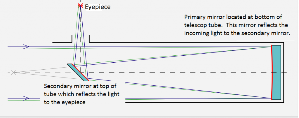
  • The reflector telescope has a curved primary mirror as its fundamental optical element. This mirror is used for creating an image at the focal plane. The distance between this mirror and the focal plane is termed the focal length. A digital sensor or film can be kept on the focal plane for recording the image produced. At times, a secondary mirror is added to redirect/forward the focused light to a film, digital sensor, or an eyepiece for visually observing the optical characteristics.
  • In a majority of modern telescopes, the primary mirror is made of a solid glass cylinder with its front surface ground to a parabolic or spherical shape. A highly reflective front surface mirror is created by vacuum to deposit a thin layer of aluminum onto the mirror.
  • Different methods make primary telescopes. One such method involves rotating molten glass in order to make it is surface a paraboloid. This is continued till the glass cools down and solidifies. The mirror developed is paraboloidal in terms of shape approximately and requires minimal polishing and grinding for achieving the accurate figure.

Why are reflecting telescopes used for astronomical research?

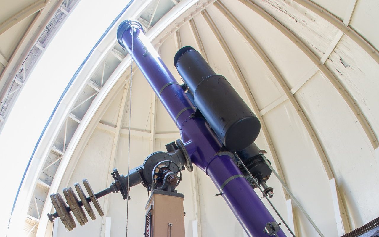
Cronyn Observatory 254mm refractor edited
Avocet7Cronyn Observatory 254mm refractorCC BY-SA 4.0

At present, almost all large astronomical telescopes used for research are reflectors/reflecting telescopes. There are a variety of reasons why the reflectors are preferred for astronomical research:

  • · The glass elements/lenses used in refracting and catadioptric telescopes absorb specific wavelengths of light or a certain amount of incoming light. Reflectors do not absorb any such wavelength, and hence, they work on a broader spectrum of light.
  • · For a lens to work correctly, it should be devoid of any form of aberration, imperfection and inhomogeneities. The entire structure should be accurate. But in the case of mirrors. Only the reflecting surface requires to be perfectly polished.
  • · Lenses are made up of different materials with different refractive indices. Different wavelengths of light travel at different speeds and angles in different mediums. This results in giving rise to chromatic aberration. In order to correct these aberrations, one needs to incorporate a combination of two or more aperture-sized lenses. This increases the monetary investment of the system and also makes it significantly bulkier. The images formed by mirrors do not suffer from chromatic aberration. Moreover, mirrors prove out to be comparatively cost-efficient and are compact in size.
  • · Manufacturing and setting up lenses with large apertures can create problems. Lenses can be attached only with their edge. The central part of the lens slumps because of gravity. This leads to the distortion of the image formed. Using mirrors eradicates the possibilities of such problems. Mirrors can be held with back support and hence, can have large apertures without affecting image formation. The largest lens aperture currently stands at 1 m, whereas the largest mirror aperture stands at 10 m. 
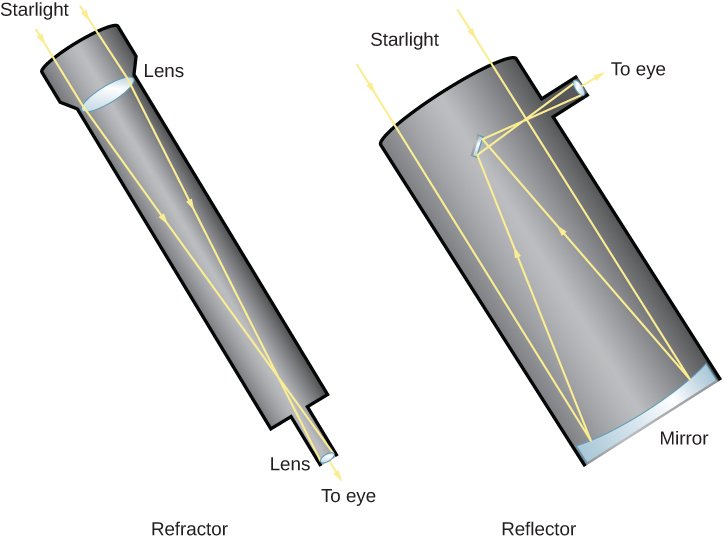
Representation of light path. Source: OpenStaxOpenStax Astronomy refracting and reflecting telescopesCC BY 4.0

What are the different designs of reflecting telescope?

  • The Gregorian telescope (proposed by James Gregory) uses a concave secondary mirror to reflect the primary mirror’s image through a narrow hole. This is done to produce an upright image that is advantageous for conducting terrestrial observations. There are a few small spotting telescopes that are constructed in this manner. Many large modern telescopes also use the Gregorian arrangement. For example, the Magellan telescopes, the Vatican Advanced Technology Telescope, the Giant Magellan Telescope, and the Large Binocular Telescope.
reflecting telescope
Path of light of a Georgian Reflecting telescope.
image source:KrishnavedalaGregorian telescopeCC BY-SA 4.0
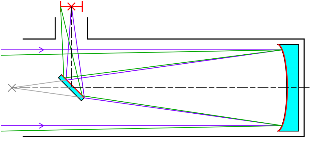
  • The Newtonian telescope is a reflecting telescopic design variation that was developed by Sir Isaac Newton in the year 1668. Such telescopes incorporate a concave primary mirror and a flat diagonal secondary mirror. The Newtonian telescope is famous due to its effective and simplistic design, which is appreciated by telescope makers. In this design, the eyepiece is located at the top end of the telescope tube. The placement of the eyepiece with short focal ratios provides a compact mounting system, ensures mobility, and brings down the expenditure. [To know more about Newtonian telescope visit https://lambdageeks.com/newtonian-telescope/]
1920px Newtonian telescope2.svg 1
Path of light of a Newtonian Reflecting telescope. Image source: Krishnavedala – Own work CC BY-SA 4.0
  • The Cassegrain telescope that was developed by Laurent Cassegrain in the year 1672 incorporates a parabolic primary mirror and a hyperbolic secondary mirror for reflecting the incident light to the primary mirror through a small hole. The secondary mirror is primarily used for diverging and folding. This results in a telescope having a short tube length with a long focal length. [To learn more about Cassegrain telescope visit https://lambdageeks.com/cassegrain-telescope/]
1920px Cassegrain Telescope.svg
Path of light of a Cassegrain Reflecting telescope. Image source; Krishnavedala – Own work CC BY-SA 4.0
  • The Ritchey–Chrétien telescope (developed by George Willis Ritchey and Henri Chrétien around 1910s) is a special Cassegrain reflector. This design has two hyperbolic mirrors instead of a parabolic primary mirror. The Ritchey–Chrétien telescope is free of coma and spherical aberration and provides a nearly flat focal plane. This telescope is apt for wide-field and photographic observations. The Ritchey–Chrétien telescope design happens to one of the most commonly used professional reflector telescopes.
  • The Dall–Kirkham telescope is another special type of Cassegrain telescope design. The Dall–Kirkham telescopic design is comparatively easier to construct than a regular Cassegrain or Ritchey–Chrétien telescope. However, this design is unable to correct the issues of off-axis coma. Its small field curvature makes it less evident or accurate at longer focal ratios; hence, Dall–Kirkham telescopes are barely seen to be faster than f/15.
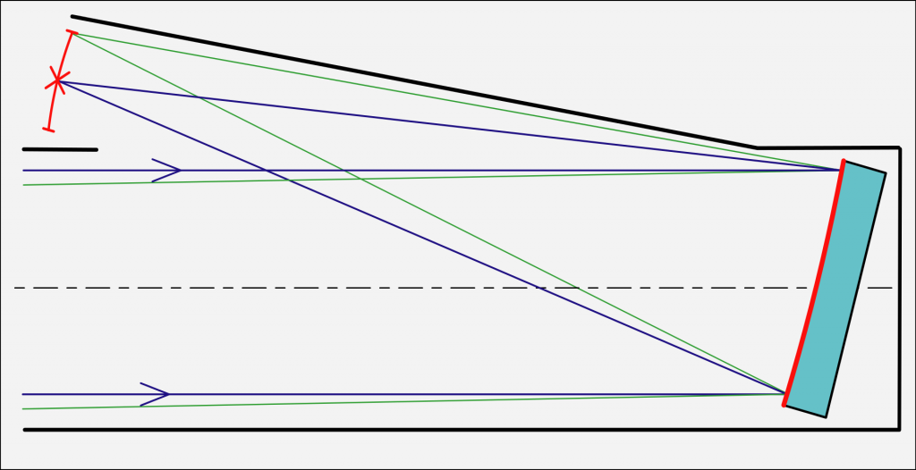
  • The Herschelian reflector (proposed by William Herschel in 1789) is incorporated for building very large telescopes. The Herschelian design uses a tilted primary mirror. This ensures that the light is not blocked by head of the observer. However, this reflector design comes with certain geometrical aberrations. Irrespective of that, it is used for avoiding the use of a Newtonian secondary mirror. The secondary mirror is generally built up of speculum metal mirrors that gets tarnished fast and provides a reflectivity of only 60%.
1920px Herschel Lomonosov reflecting telescope.svg
Path of light of a Herschelian Reflecting telescope. Image source: User:Eudjinnius – Own work
Diagram of Herschel-Lomonosov telescope system. CC BY-SA 3.0

What are the errors produced by reflecting telescope?

Reflecting telescopes are prone to producing specific errors while forming images, just like any other optical system. The images formed has object distances up to infinity, and these images are viewed at different light wavelengths. These factors cause specific errors in image formation.

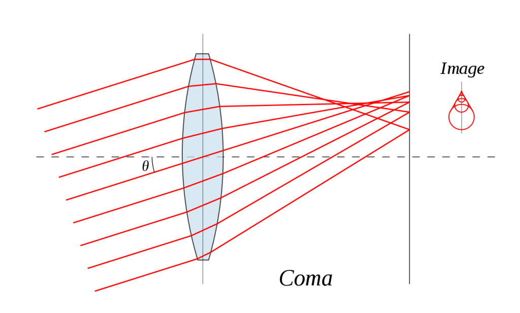
  • Coma – Coma is a type of aberration that focuses the center of the image to a point, but the edges generally appear radially smudged (comet-like) or elongated.
1280px Lens coma.svg
Diagramatic representation of comatic aberration, anonymous, Lens-comaCC BY-SA 3.0
  • Field curvature – At times, the images are not focused well all across the field. This happens due to the image plane’s curvature and is corrected by using a field flattening lens.
    • Astigmatism – Astigmatism is a type of aberration that causes an azimuthal focal variation around the aperture. As a result of this, off-axis point source images appear elliptical. Astigmatism causes more error when the field of view is large and starts varying quadratically with field angle. In the case of a smaller/narrower field of view, astigmatism is not usually a problem.
1920px Astigmatism.svg
Diagramatic representation of Astigmatism. I, Sebastian Kroch, AstigmatismCC BY-SA 3.0
  • Distortion – Distortion is an aberration effect that disturbs the shape of the image. Image sharpness is not affected by distortion. This aberration is generally corrected with the help of image processing. 
  • Spherical aberration: Spherical aberration is a defect that occurs when a spherical mirror/lens is unable to focus light from different distant objects at the same point. This defect is solved by using parabolic mirrors instead of the spherical ones. However, the parabolic mirror does not work well with image formation of light falling on the edge of its field of view and produces off-axis aberrations. 

To know more about lens measurement visit https://lambdageeks.com/a-detailed-overview-on-lensometer-working-uses-parts/

To know about parts of a telescope visit https://lambdageeks.com/steps-to-use-a-telescope-parts-of-a-telescope/

Read more about Galilean Telescope.

Also Read:

The Definitive Guide to Newtonian Telescopes: A Comprehensive Exploration

newtonian telescope

Newtonian telescopes are a type of reflecting telescope that use a primary mirror and a smaller secondary mirror to collect and focus light. They are known for their simplicity, affordability, and versatility, making them a popular choice among amateur astronomers. This comprehensive guide will delve into the technical details and specifications of Newtonian telescopes, providing a valuable resource for science students and enthusiasts alike.

Understanding the Aperture and Its Significance

The aperture of a Newtonian telescope is the diameter of the primary mirror, which is a crucial specification that determines the amount of light the telescope can collect. The aperture is directly proportional to the light-gathering power of the telescope, as described by the formula:

Light-gathering power = (Aperture diameter)^2

For example, the AWB 130 Newtonian Telescope has an aperture of 130mm, which is considered a medium-sized telescope. A larger aperture allows for more light to be collected, resulting in a brighter and clearer image, enabling the observation of fainter celestial objects.

Focal Length and Focal Ratio: Balancing Magnification and Field of View

newtonian telescope

Another important specification of a Newtonian telescope is the focal length, which is the distance between the primary mirror and the point where the light converges. The focal length determines the magnification and field of view of the telescope.

The focal ratio, denoted as f/x, is the ratio of the focal length to the aperture diameter. This ratio is a key factor in the telescope’s performance:

  • A telescope with a low focal ratio (e.g., f/4) has a wide field of view and is well-suited for observing large targets such as galaxies and nebulae.
  • A telescope with a high focal ratio (e.g., f/10) has a narrower field of view and is better for observing detailed features of planets and the moon.

The relationship between focal length and magnification is given by the formula:

Magnification = Focal length of the eyepiece / Focal length of the telescope

By carefully selecting the focal length and focal ratio, amateur astronomers can optimize their Newtonian telescopes for specific observational goals.

Mirroring Perfection: The Importance of Primary Mirror Quality

The quality of the primary mirror is crucial for the performance of a Newtonian telescope. The mirror should be figured (i.e., ground and polished) to a precise parabolic shape to minimize optical aberrations, such as coma and spherical aberration. The Standard Handbook for Telescope Making provides detailed instructions on how to figure and test a telescope mirror.

The surface quality of the mirror is also essential, as any imperfections or irregularities can degrade the image quality. The mirror’s reflectivity, determined by the coating material, also plays a role in the telescope’s light-gathering efficiency.

DIY Newtonian Telescope Building: A Hands-on Approach

For DIY enthusiasts, building a Newtonian telescope can be a rewarding and educational experience. Mel Bartels’ website, for example, provides detailed instructions on how to design and build a Newtonian telescope, including tips on choosing the right materials and tools.

When building a Newtonian telescope, key considerations include the mirror’s diameter, focal length, and the overall mechanical design to ensure stability and alignment. Proper mirror figuring and testing are also crucial steps in the construction process.

Newtonian Telescopes and Astrophotography: Balancing Focal Length and Field of View

Using a Newtonian telescope for astrophotography requires careful consideration of the trade-offs between focal length, field of view, and tracking accuracy. A longer focal length can provide higher magnification and resolution, but it may also result in a narrower field of view and increased sensitivity to tracking errors.

Conversely, a shorter focal length can provide a wider field of view and greater tolerance for tracking errors, but it may sacrifice resolution and magnification. The quality of the optics and the mount are also crucial for capturing sharp and detailed images.

Astrophotographers may need to experiment with different focal lengths and techniques to achieve their desired results, such as using focal reducers or Barlow lenses to adjust the effective focal length.

Conclusion

Newtonian telescopes are a versatile and popular choice among amateur astronomers, offering a balance of performance, affordability, and customization. By understanding the key specifications, such as aperture, focal length, and mirror quality, science students and enthusiasts can make informed decisions when selecting or building their own Newtonian telescopes.

Whether you’re interested in visual observation, astrophotography, or simply the joy of hands-on telescope building, this comprehensive guide provides the technical details and practical insights to help you explore the wonders of the night sky with a Newtonian telescope.

References:
– Dr. D on the AWB 130 Newtonian Telescope – YouTube. https://www.youtube.com/watch?v=pKM6439t0KM
– Newtonian Reflecting Telescope Designer – Mel Bartels. https://www.bbastrodesigns.com/HET.html
– The Definitive Newtonian Reflector – Articles – Cloudy Nights. https://www.cloudynights.com/articles/cat/articles/the-definitive-newtonian-reflector-r2983
– Choosing a NEWTONIAN reflector 8″ F5 (perhaps F4) FOR photometry – Cloudy Nights. https://www.cloudynights.com/topic/718078-choosing-a-newtonian-reflector-8-f5-perhaps-f4-for-photometry/
– Making and Testing a Telescope Mirror – Geocities.ws. https://www.geocities.ws/kms_goldilocks/techpaper/index.html