Cam and Follower: Definition, Types, Working Principle, Advantages, Applications

Diagram Low 2

Table of Content

Cam and follower

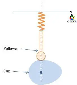
Cam and follower is a mechanism used to get the desired motion such as reciprocating or translational from an available input, usually rotational.

Cam and follower with different size and shape are available in the market.

The elements of the mechanism are;

  • Cam
  • Follower

Diagram of cam and follower

Cam and follower

What is a Cam?

Cam is the driving component in the mechanism, making sure that the follower follows the desired motion.

Hence, the profile and size of the cam are significant in a cam and follower mechanism.

While designing the mechanism, the main concern goes to getting the appropriate profile of the cam.

What is a follower?

The component which gives the desired motion in the mechanism is the follower. The motion of the follower is the output in the cam follower mechanism.

Generally, followers are having two distinct types of motions, oscillating and reciprocating. The followers are designed in such a way that, it always touches the cam during the cam operation.

As the follower moves over the cam, there is friction resistance and side thrust acting. The friction resistance leads to the wear failure of the cam follower mechanism.

Classification of cam and follower | Different types of cam and follower

There are different types of cams and followers available according to the applications.

Those are discussed below;

Types of Cams

The cams can be classified as follows;

Cam Working Low 2

Types of cams : based on the shape

  • Plate or disk cam

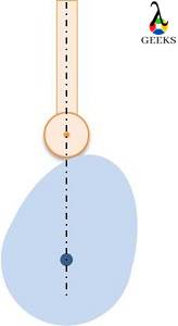
It is the most commonly used cam. It is cut from a metal disk or plate to a pre-planned shape according to the requirement.

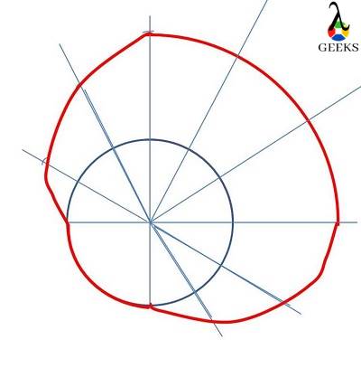
Many important cam parameters can be explained using the plate cam, like the base circle, pressure angle, pitch point, etc.

.
Cylindrical follower low 6
  • Cylindrical cam

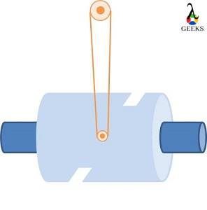
The cam is of cylindrical shape. A groove is cut on the surface of the cylinder and follower moves inside the groove. The cylinder rotates, and the follower oscillates accordingly.
Cylondrical Cam Low 3
  • Wedge cam

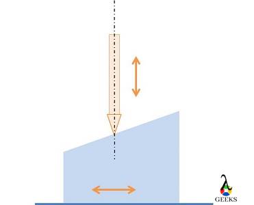
The figure shows a wedge cam. Wedge cams have a wedge of specified shape that reciprocates and leads to reciprocation or oscillation of the follower.
Wedge Cam low 3
  • Spherical cam

A spherical cam is similar to a cylindrical cam; the only difference is groove is cut on a sphere instead of a cylinder.

  • Globoid cam

Globoid cam is also similar to cylindrical cam; the only difference is grove is cut on a globoid shape.
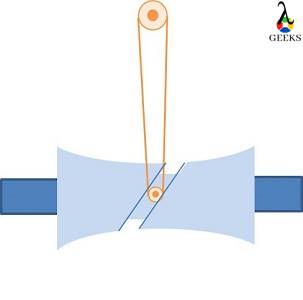
Globoidal Cam Low 3
  • Conjugate or dual cam

The conjugate cam consists of two-disc cams that are bolted together. This type is used for very quiet operations.

Types of cams : based on follower movement

The follower movement can be classified as,

  • Dwell – No movement to the follower.
  • Rise or Ascend – The follower moves upward.
  • Return or Descent – The follower moves downward.

The cam profile controls the length and amount of ascend, descend or dwell in a cam follower mechanism. Hence, according to the follower movement, cams can be classified.

By proper design of cam profile, any combination dwell, rise or return can achieve. In each cycle, the follower comebacks to the initial state. Hence, if there is a ascend, then the equal amount of descent will be there in the cam profile automatically.

Some combinations are,

  • Rise, Dwell, Return cam
  • Rise, Return, Rise cam
  • Dwell, Rise, Dwell, Return, Dwell cam

Types of cams : based on the type of constraint

  • Spring-loaded: The contact between cam and follower is enabled using a pre-loaded spring.
Spring Cam low 2
  • Positive drive: Providing groove as shown in cylindrical cam is an example of a positive drive cam. Here, the follower motion is constrained due to the presence of groove.
  • Gravity cam: The gravity force helps to keep the contact between cam and follower. The follower weight should be sufficient in order to get constant contact.
Springless Low 2

Types of Followers

The followers can be classified as follows;

Follower Types Low 3

Types of Followers : Based on the shape of the follower

  • Knife edged follower

An example of a knife-edge follower is given in the figure. It is having a sharp edge, i.e., knife edge, making contact with the cam.

We can expect a higher frictional resistance and wear for these types of cams. And the system has considerable side thrust also. Due to these limitations, it is not commonly used.

Knife edge follower Low 2
  • Roller follower

In this follower, the pointed edge is replaced with a roller that freely rotates about its axis. Here, the frictional resistance and wear are reduced. However, the side thrust is not eliminated.

Cylindrical follower low 7
  • Flat-faced follower

It is also called a Mushroom follower. The point contact in the knife-edge follower is replaced with a flat plate, as shown in the figure. Here, the frictional resistance is not reduced; however, a considerable decrease in side thrust can be achieved.

The cam profile should have a convex shape for this type of follower; otherwise, the follower and cam get stuck in the concave profile of the cam.

FlatFaced Followe Low 2
  • Spherical faced follower

This is similar to flat-faced follower; the difference is that the contacting profile has the shape of a hemisphere; hence the frictional resistance also reduces.

Spherical follower Low 2

Types of Followers : Based on the motion

  • Oscillating follower

The follower oscillates in this type of cam follower mechanism. An example is given in the figure.
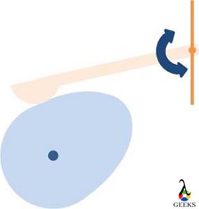
Oscilating Low 3
  • Reciprocating follower

The follower reciprocates in this type of cam follower mechanism. An example is given in the figure.

Reciprocating low 2

Types of Followers : Based on the path of the follower

  • Radial or in-line follower

In this type of followers, the cam center and line of action of the follower are in same line as shown in figure.
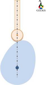
Cylindrical follower low 8
  • Offset follower or Eccintric cam follower mechanism

In this type of followers, extended line of action of follower and cam center does not lie in the same line. The side thrust is reduced if we are using an offset follower.

Offset Low 2

The Terminology of a Cam

We already discussed the importance of a cam profile.

Now we will be looking into some important terminology of the cam.

The figure shows a cam with a roller follower, indicating all the terms we are about to discuss.

Cam Terminology Low 2

The roller at the different positions over the cam is shown, assuming the cam remains stationary and the roller travel along with the cam profile.

  • Base Circle 

It is the smallest circle drawn with center on the cam center and touches the cam profile.

  • Trace points

These are the arbitrary points around the cam profile, through which the center of the follower moves.

In the case of roller follower, trace points are obtained by adding the radius of the roller from the cam profile, as shown in the figure.

For knife-edge followers, the trace points are on the cam profile itself.

  • Pitch curve

If we join all the trace point we get the pitch curve.

  • Prime circle

It is the smallest circle drawn with center on the cam center and touches the pitch curve.

  • Pressure angle

Pressure angle is defined in every point in pitch curve.

It is the angle between direction of the follower movement and the normal to the pitch curve.

Higher the steepness in the cam profile, the higher the pressure angle.

Higher pressure angle is not preferred as it increases the force required to lift the follower.

  • Pitch point

It is a point in the pitch curve where the pressure angle is maximum.

  • Pitch circle

Circle with center on cam center and passes through the pitch point.

Working mechanism of cam and follower

The figure shows the cam and follower mechanism at different positions.

Cam Working 2

In the given figure, the cam rotates in an anticlockwise direction.

Initially, for some duration, the follower moves upward. The upward movement is known as the ascend or rise period (between (a) and (b)).

After that, the follower stays in the same position for some rotation of cam (between (b) and (c)).

Hereafter, the follower moves downward (between (c) and (d)), known as descend or return. At the end of the return, the follower reaches its initial position and remains stationary until the next cycle starts (between (d) and (e)).

The cycle keeps on repeating. Here, we got the reciprocating motion for the follower from the rotational movement of the cam.

The motion of the follower can be categorized as rise-dwell-return-dwell.

We can change the motion of the follower by appropriately designing the cam profile.

Imagine the follower motion for figure given below,

Special CAM Low 2

Forces acting in a cam and follower mechanism

There are mainly two forces acting in cam follower mechanism, normal force and frictional force.

Force Low 2

The direction of normal force and frictional force is shown in the figure. The normal force acts normal to the cam profile, and the frictional force acts tangential to the cam profile.

The normal force can split into two components; horizontal and vertical.

The equation for horizontal and vertical force are given below,

F_v = F_ncostheta

F_h = F_nsintheta

The vertical force is helping to lift the follower. The horizontal force is an unnecessary force, which gives a side thrust to the follower.

The angel θ is the pressure angle.

The above analysis is carried out only for normal force. The frictional force also can be analysed similarly by splitting it into horizontal and vertical components.

It can be observed that the friction force increases the side thrust and decrease the net lift force.

Side thrust in cam and follower

As explained above, the side thrust is an unnecessary force that should be reduced for the smooth operation of the cam and follower mechanism.

One component of normal force and frictional force is contributing to the side thrust.

The side thrust can be reduced by,

  • Using a flat face follower
  • Using offset cam follower mechanism.
  • Reducing the pressure angle.
  • Reducing the friction

Significance of pressure angle in cam and follower

From the above analysis, we can see that the increase in pressure angle leads to a decrease in the lift force and an increase in the thrust force. The lift force must be sufficient to overcome the spring force or gravitational force in the cam follower mechanism. Hence, if the pressure angle is very high, high energy is required to lift the follower.

Therefore, the pressure angle is usually kept as low as possible in the cam follower mechanism.

Cam follower design

Now, we discuss how to design a cam follower mechanism.

The design of cam profile is the primary step in manufacturing of the cam follower mechanism.

The cam profile depends on the size of the follower, type of follower, and the kind of motion required.

Constant velocity, constant acceleration and simple harmonic motion are some of the motions in cam and follower mechanism.

The cam profiles are different for getting the above motions.

Before discussing the cam profile, we should know about some terms.

Angle of ascend : The angular rotation of the cam during the ascend of follower is known as angle of ascend.

Angle of dwell: It is the angular rotation of the cam during the dwell period.

Angle of descend: It is the angular rotation of the cam during the return period.

Lift or stroke: The distance travelled by the follower during the rise or return period.

Now, let’s discuss designing a cam profile.

The critical step in designing the cam profile is drawing a displacement diagram.

The displacement diagram is the graph plotted between the angular distance of the cam and the lift of the follower.

The displacement diagram varies for different motions.

After getting the displacement diagram, we have to transfer the distance to the base circle to get the cam profile.

Displacement diagram

The displacement diagram for different motions is explained in this section.

The angle of ascend, dwell, descend, and lift of stroke are predefined variables.

Now let’s assume that the angle of ascend, dwell, and descend, and lift of stroke are 90o, 90o, 90o, and 10cm, respectively.

Drawing different displacement diagrams are explained below;

Constant velocity

  • Draw x axis and y axis, mark the angles in x axis and lift in y axis.
  • Mark the ascend, descent, and dwell in x axis.
  • Join the left bottom corner and right top corner in ascend to get the displacement of follower during the rice period.
  • During the dwell period, the displacement curve will be parallel to the x-axis.
  • Join the left top corner and bottom right corner for drawing the displacement curve during the descend.
Constant Velocity Low 2

Constant acceleration

The figure shows drawing the displacement diagram for ascend.

constant accelaration Low 3
  • Divide the angle of ascend to even number of parts (n parts). And draw vertical lines.
  • Mark the center line and divide it into n parts.
  • Draw a line from the bottom left corner to each point in the centerline till n/2 parts, do the same for the remaining point from the top right corner.
  • Mark point of contact between 1st vertical line and 1st inclined line and 2nd vertical and 2nd inclined line and so on.
  • Join the points.

Simple harmonic motion

The figure shows drawing the displacement diagram for ascend.
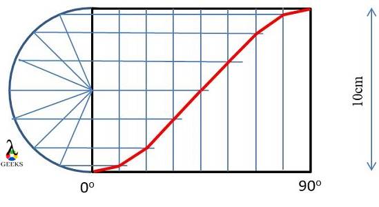
Simple Harmonic Low 2
  • Divide the angle of ascend to n number of parts. And draw vertical lines.
  • Draw a semi-circle in the y axis with diameter equals to lift, divide it into n parts.
  • Now, draw a horizontal line from each point on the semi-circle to the corresponding vertical lines.
  • Joint the point of contact between the horizontal line and vertical line.

Drawing cam profile

The figure shows the cam profile for the constant velocity profile mentioned above.

The steps involved in drawing cam profile from displacement diagram are,

  • Draw the base circle.
  • Mark ascend, descend and dwell period in the base circle.
  • Divide ascend, and descend to equal parts similar to displacement diagram.
  • Measure the distance from the x-axis to the curve in displacement diagram for each vertical level.
  • Mark the measured distance from the base circle for each vertical level, respectively.
  • Join the pints
Cam profile Low 2

Cam and follower material selection

For most applications, the cam is manufactured using metals. Steel alloys and cast irons are most commonly used material.

The thermoplastic like nylon and polypropylene are used in some cases.

How to build a cam and follower?

Here we discuss the manufacturing technique used for producing cam and follower.

Initially, we have to design the cam and follower and study the forces acting, stress-induced, the maximum load the cam follower pair can handle, etc. Generally, SolidWorks software is used to design the cam and follower mechanism.

For thermoplastic materials, impact molding is used for manufacturing.

For metal cams variety of manufacturing techniques is used. Conventional manufacturing techniques like grinding, milling, cold forging, etc., are used to produce cam. For high accuracy, CNC machining is used. Powder metallurgical techniques are also used in many situations.

Degree of freedom of cam and follower

The degree of freedom of cam and follower should always be one.

The degree of freedom indicates the number of independent variables to define the motion of the system. Degree of freedom 1 means we need one independent variable to describe the motion. That means the movement between the links is only possible in one way. If we rotate the cam, the follower will only reciprocate; it will not reciprocate and oscillate together.

The constraints are provided to make sure that the degree of freedom of the system is one.

Applications of Cam and Follower

  • IC engines
    • Opening and closing of inlet and exhaust valve.
    • Operating fuel pump
  • Automatic lathe
    • feed mechanism
  • Toys
  • Wall clocks

Cam and follower advantages and disadvantages

Advantages of cam follower mechanism

  • By proper designing of cam profile, a variety of follower motions can be obtained.
  • Able to operate accurately.
  • Easy mechanism to convert the rotational motion to reciprocating or oscillating motion.
  • The number of components reduces with the use of a cam and follower mechanism.
  • Compact

Disadvantages of cam follower mechanism

  • Subjected to wear, hence, can be used only when the transmission force is less.
  • Accurate manufacturing is required.
  • High manufacturing cost.
  • There is a limitation to the size of the mechanism. Large size is challenging to operate.

Cam and follower objective questions

  1. During the rise or ascend period, the follower is;
    1. Moving up
    2. Moving down
    3. Stationary
    4. None of the above

Ans: 1

  1. In cam and follower, friction should be
    1. High
    2. Low
    3. Medium

Ans: 2

  1. The side thrust can be reduced if we use;
    1. Roller follower
    2. Knife edge follower
    3. Flat plate follower

Ans: 3

Cam and follower problem

Try to answer the given problem yourself,

  • Draw displacement diagram and cam profile for following conditions,

Follower Type: Knife-edge follower

Lift : 6 cm

Base circle radius: 6 cm

Angle of ascend: 60

Angle of dwell: 120

Angle of descend: 60

Motion type during ascend: Simple harmonic motion.

Motion type during descend: Simple harmonic motion.

Important Questions and Answer 

What is the difference between cam and follower?

Cam is the driver in the cam and follower mechanism, which reciprocates or rotates. The follower is the driven component, which oscillates or reciprocates. The ultimate aim of the cam and follower mechanism is to get the desired motion for the follower.

Cam and follower motion?

The cam and follower can have a different combination of motions.

The cam usually rotates(cylindrical, plate cams) or reciprocate (wedge cam)

The follower oscillates or reciprocate.

Is a cam follower a lifter?

Yes

Cam and follower types

A detailed description is given in the above content.

Why are ‘offsets’ required in cam and followers?

The offset is used to reduce the wear and side thrust.

In physics mechanics, how come a cam follower is a higher pair?

The classification of higher pair and lower pair is based on the contact between the links. The nature of contact is point (knife-edge follower) or line (roller follower) in the cam follower mechanism. Hence it is higher pair.

What is the significance of pressure angle in Cam followers?

The pressure angle indicates the steepness of the cam profile.

An increase in pressure angle leads to a decrease in the lift force and an increase in the thrust force. The lift force must be sufficient to overcome the spring force or gravitational force in the cam follower mechanism. Hence, if the pressure angle is very high, high energy is required to lift the follower.

Therefore, the pressure angle is usually kept as low as possible in the cam follower mechanism.

Why is the roller follower preferred over the knife-edge follower?

The roller follower is preferred over the knife-edge follower to reduce the friction, hence the wear of the follower.

What is the pressure angle and methods to control the pressure angle of a cam?

Pressure angle is defined at every point in the pitch curve.

It is the angle between the direction of the follower movement and the normal pitch curve.

Methods to reduce pressure angle;

  • Use offset follower
  • Increase the size of cam
Forming Process: 31 Important Factors Related To It

1 5

keyword

Forming is type of manufacturing process used very widely through out the world and is one of the old technique. Following are the points we are going discuss in detail in this article:

Content

What is forming? | Fundamentals of metal forming processes

Forming/ Metal forming is a process in which material deforms plastically to get the required shape by application of force in such a way that the stress generated should be greater or equal to yield stress, and simultaneously, it should be less than the ultimate stress of the material.

\\sigma y\\ \\leq \\sigma \\ \\leq \\sigma u

Types of forming process | Forming process in manufacturing | Bulk metal forming processes | Metal forming processes | Forming operations | Type of forming operations | Different types of forming | | Classification of metal forming process | Types of plastic forming

Metal forming:

1) Bulk metal forming: 

  1. Forging
  2. Rolling
  3. Extrusion 
  4. Wire forming

2) Sheet metal forming

  1. Bending
  2. Deep cup drawing
  3. Shearing
  4. Stretching
  5. Spinning

3) Advanced metal forming

  1. Super plastic forming
  2. Electroforming
  3. Fine and banking operation
  4. Hydro forming
  5. Laser forming
  6. Powder forming

Microstructure evolution in metal forming processes

When metal forming is carried out, the material goes under very high stress to change it shape. The microstructural change in the material take place. But the formation of crystals will only re arrange if it is hot work, that is worked above recrystallization temperatre. That is the material is heated above its recrystallization temperature and forming is carried out.

Temperature in forming processes | Hot metal forming processes | Cold metal forming processes | Effect of temperature on metal forming process

  • Temperature stands to be a very important factor in the manufacturing process, as the material properties are a function of the temperature.
  • The working in forming process is divided into three parts on basics of temperature:
  • 1. Cold working
  • 2. Warm working
  • 3. Hot working
  • Before defining the above points, let us know what Recrystallization temperature is.

Recrystallization temperature:

  • The temperature at which the material will reform the arrangement of its crystal is known as recrystallization temperature.
  • It is unique value for each material
  •  Lead, Tin, Zinc, and Cadmium is the material whose recrystallization temperature is equal to the room temperature and hence work perform on this materials is always hot work.
  • Recrystallization temperature ranges from 0.5 to 0.9 times of melting temperature of the material.

Cold working:

  • When work is done on the material, when material’s temperature is below the Recrystallization temperature, such work comes under the category of cold working.
  • The amount of force and energy required in cold working is very high.
  • The accuracy is quite good in cold working as compared to others.
  • Properties like Strength and Hardness increase. 
  • While the properties like malleability and ductility reduce.
  • Friction acting in cold working is low.

Warm-working:

  • When work is done on the material at a temperature above cold working but less than the recrystallization temperature, it comes under the category of warm working.
  • It is preferred over cold working when the amount of force applied is less.

Hot working:

  • When work is done on the material, material’s temperature is greater than the Recrystallization temperature, such work comes under the category of hot working.
  • The amount of force and energy required in hot working is less.
  • The accuracy maintains poor in hot working as compared to others.
  • Properties like Strength and Hardness decrease.
  • While the properties like malleability and ductility increase.
  • Friction acting in hot working is high.

Types of cold forming process

Cold forming techniques: squeezing process, bending process, drawing process, and shearing process. 

Squeezing process consist of:

  • Rolling process,
  • Extrusion process,
  • Forging process,
  • Sizing process

Bending process consist of:

  • Angle bending process,
  • Roll bending process,
  • Roll forming process,
  • Seaming process,
  • Straightening process
  • Shearing process consist of:
  • Sheet metal shear-cutting process,

Blanking.

  • Drawing process consist of:
  • Wire drawing process,
  • Tube drawing process,
  • Metal spinning process,
  • Sheet metal drawing process,
  • Ironing process

Friction and lubrication in metal forming process | Friction in metal forming process

  • friction in metal forming take place due to close contact of work piece surface and the tool (die, punch) at high pressure (Also high temperature for some operation).
  • This high pressure, high compressive stress and also friction plays a very important role in forming of the product.
  • But over 50% of energy is required to overcome tis friction.
  • Surface quality is retarded, the tool and die life is reduced.
  • To overcome such undesirable effects lubrication is introduced

To overcome the friction lubrication is carried out:

Lubrication in metal forming process | Types of lubricants used in metal forming

Metal forming uses lubrication: water-based, oil-based, synthetic and solid film

  • Water based: they good for cooling purpose but are has less lubricity. They are mostly used for high speed application.
  • Oil-based: It overcome draw backs of water based lubricant but you lack additive solubility.
  • Synthetic: with solubility it also provides good lubricity.
  • Solid film: can be used with or without oil/water, mostly used for high pressure, low speed and low temp application.

Advantages and disadvantages of metal forming process

Advantages:

  • Material wastage is negligible or zero (As no shear/ cutting action involved).
  • Grain can be oriented in required direction
  • By cold working strengthens and hardness is increasing, while by hot working the ductility and malleability increases.

Limitations:

  • Force and energy required is very high
  • Automation is required, therefore it is costly
  • Except forging all other process can produce uniform cross section.
  • Crossover and undercut are difficult to produce.

Applications of metal forming process

  • Channels of direct shape. 
  • Seamless tubes
  • Turbine-rings.
  • Hardware products like nail, hails
  • Agricultural tools used for sawing and cutting.
  • Military products
  • Automobile structure parts doors, outer body shield. 
  • Different plastic products

Rolling 

Rolling is a process when the required shape is obtained by passing the material through rollers. This rollers are places with distance between them, which is define by the required thickness of the output product. As material is forced to pass through this gap the high force is also applied by the rollers. The number of rollers depends on application of force.

FORMING PROCESS
rolling process

Rolling is carried out by the following methods:

1.) Hot rolling

2.) Cold rolling

3.) By application of front and back tension

Roll forming (hot)

  • Hot rolling is a rolling process (also known as hot working) when the material is heated above its recrystallization temperature before passing it through the rollers.
  • Malleability and ductility increase while strength and hardness decreases
  • Surface finish and dimension accuracy is poor
  • Force and energy required is less as compared to cold rolling
  • Friction is high

Roll forming (cold)

  • Cold rolling is a rolling process (also known as cold working) when the material is heated below its recrystallization temperature before passing it through the rollers.
  • Malleability and ductility decreases while strength and hardness increases
  • Surface finish and dimension accuracy is excellent
  • Force and energy required is more as compared to hot rolling
  • Friction is low

Types of roll forming machine

  • Two-high rolling-mills
  • Three-high rolling-mills
  • Four-high rolling-mills
  • Cluster rolling-mill
  • Planetary rolling-mill
  • Tandem rolling-mill

Sheet metal forming processes and applications | Sheet metal forming processes and die design | Sheet metal roll forming process | Sheet metal forming processes and applications

In forming sheet metal operation the material is deform plastically and no cutting action is carried out.

The force applied in sheet metal forming operation is more than the yield stress so as to carry the deformation but less than the ultimate stress as not cutting action in carried out in forming process.

\\sigma y\\ \\leq \\sigma \\ \\leq \\sigma u

Different types of sheet metal forming processes | Types of sheet metal forming process | Types of sheet metal forming processes

  • Bending
  • Deep cup drawing
  • Shearing
  • Stretching
  • Spinning

Bending

Bending is a sheet metal forming operation is where metal is bent in the required direction by applying force with the help of punch and die components. When bending occurs, the outside layers of the sheet go through tension while the inside layer goes through compression. If the stretching is excessive, there might be a chance of shifting the neutral plane towards the center of curvature.

2 3
bending

Stretch forming | Types of stretch forming

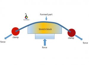
It is sheet metal forming process in which the selected sheet is stretch and bended continuously over a die to get the required shape. It acquires the shape of the die.

3 2
stretch forming

Types of the stretch forming:

  • Longitudinal stretch forming
  • Transvers stretch forming

Deep drawing metal forming process

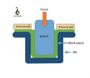
Manufacturing of cup from a raw sheet blank with the help of the punch and die is called deep drawing or cup drawing process, Here the material is deformed plastically to get the required shape. It is a sheet metal forming operation hence no cutting action. Punch is used to apply the force to create plastic deformation of the material. And it gets the shape of the die and punches while going through series of bending, stretching, straighten up to produce a vertical deformation wall of a deep-drawn component.

4 2
deep dawing

Guerin process metal forming

guerin process metal forming is a subpart sheet metal forming process. In this process the sheet metal is stamped with help punch to get desirable result. It is simple shaping of sheet metal by stamping process.

Metal press forming process

Metal press forming is very simple process in which sheet metal is hold with help of the clamps and shaped with help die and punch. It is same as the stamping process.

Spinning process in metal forming | Spinning process in sheet metal forming

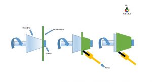
In this process the disc of the metal sheet is used as raw product. It is clamp over the spinning machine against the mandrel. The disc of sheet is pressed against the high speed rotating mandrel with help of the press tool. The symmetric objects are manufactured in this process. It can be carried out on the CNC machine.

6 1

Roll forming process in sheet metal

Roll forming in sheet metal is a process when the required shape/size is obtained by passing the sheet metal through rollers. This rollers are placed with distance between them, which is define by the required thickness of the output product. As material is forced to pass through this gap the high force is also applied by the rollers. The number of rollers depends on application of force

Types of roll forming

  • Two-high rolling-mills
  • Three-high rolling-mills
  • Four-high rolling-mills
  • Cluster rolling-mill
  • Planetary rolling-mill
  • Tandem rolling-mill

Defects in sheet metal forming process

Defects in sheet metal:

Wrinkle: the folding create at inside of the deep drawn component is called wrinkle. It can be eliminated by applying blank holding force along strip plate.

Earing defects: The folding created at the flange end of the deep drawn component is called as the earing defect. It is generated because of circumferential compressive stress or anisotropic properties of material. 

It can be eliminated by cutting the material after deep drawing operation by trimming process. The amount of material trimming comes under the trimming allowance.

Scratches: In a deep drawing process because of the friction present between component and the die scratches are generated and it reduces surface quality. It can be eliminated by proper lubrication.

Corner crack or fracture: corner crack or fracture are generated at the bottom of the deep drawn components because of thinning of material and stress concentration. 

Orange peel: When annealing of the deep drawn component is done above recrystallization temperature it is observe that the grain get expanded independently and produce coarse size of grain. Which has some structure like peel of orange. Therefore it is called as orange peel.

Advantages and disadvantages of sheet metal forming process | Advantages of sheet metal forming process

Advantage:

  • Production rate is high
  • Minimum waste
  • Uniform density
  • Simple process
  • High strength
  • Good surface finish

Disadvantage:

  • High force required
  • Heavy machineries
  • Automation required
  • Somewhat poor in maintain accuracy

Forging

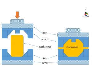
Forging is a process in which material if deforms plastically to get the required shape by applying high compressive force with the help of hammers. The compressive force is applied at a particular location several times to get the final product.

7 1
forging

Mostly forging uses a hot working process.

Extrusion | Extrusion metal forming process | Extrusion process in metal forming

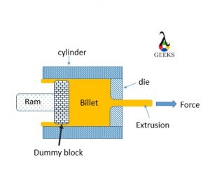
Extrusion is a process where a billet is placed inside the stationary cylinder with one end attach to opening with die (Output shape) and another end has a ram to apply the force. 

When the force is applied to a solid billet, it acts in a hydrostatic compressive manner.

At one point, this value will reach the flow stress value of the material, where the entire solid material will become extremely soft, like a gel, and will flow through the die, with the shape of the die.

8 1
Extrusion

Extrusion types:

1) Forward/direct extrusion: Hydrostatic extrusion.

2) Backward/ indirect extrusion: Impact extrusion or hollow back extrusion.

Wire drawing | Drawing metal forming process

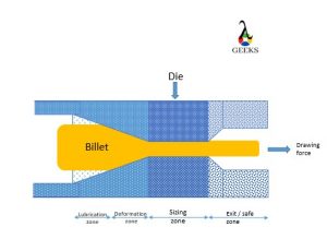
Wire drawing is a process where the billet is given the shape of required output by pulling it through a die rather than Appling force from backward as the extrusion.
A typical wired drawing can de dived in four zone.

wire drawing
wire drawing

Zone 1: Deformation Zone

The entry diameter of the zone is equal to the rod diameter of the zone, while the end diameter is the diameter of the wire needed to be. Therefore whatever deformation is required to convert the rod into wire takes place in this zone. It is known as the deformation zone. The total included angle of the stented surface of the deformation zone is called as die angle or deformation angle.

Zone 2: Lubrication Zone

This zone is used to supply lubricant to reduce friction and let the process carry out smoothly. If the lubrication is not provided, it dull, rough, and unpleasant surface finish of the wire.

Zone 3: sizing zone

This zone is just used to maintain the same load for some time to convert elastic deformation into permanent plastic deformation.

Zone 4: Exit or Safety zone

This zone is used for collecting high-pressure and high-temperature lubricants.

Punching metal forming process

Punching is process in which punch is used to apply the force on the work piece to get required output and the result may be in form of the cutting/ shear action depending upon a material. It is mostly used to create holes in a metal sheet.

Advanced metal forming processes | Advanced metal forming process

  • Super plastic forming
  • Electroforming
  • Fine and banking operation
  • Hydro forming
  • Laser forming
  • Powder metal forming process

Powder metal forming process

Power metal forming is process in which raw material is in powder form and is well mix for desired output product composition. The powder is push into the die and the punch is used to apply the force and hold it for a time. To increase the density of the product the heat application is also introduced. It is used to manufacturing of self-lubricating bearing.

Blanking metal forming process

Blanking is the specialized precision metal forming process that includes extrusion in cold manner and advanced stamping techniques. It gives clean and good dimension accuracy products, but cost is very high.

Mostly used to manufacture automobile and electronic parts

Types of plastic for vacuum forming

  • Acrylonitrile Butadiene Styrene
  • Acrylic – Perspex
  • Co-Polyester
  • Polystyrene
  • Polycarbonate
  • Polypropylene
  • Polyethelene

FAQ’S

What are the different metal forming processes | Types of metal forming process | what are the different types of forming | Metal forming process example

1) Bulk metal forming: 

  • Forging
  • Rolling
  • Extrusion 
  • Wire forming

2) Sheet metal forming

  • Bending
  • Deep cup drawing
  • Shearing
  • Stretching
  • Spinning

3) Advanced metal forming

  • Super plastic forming
  • Electroforming
  • Fine and banking operation
  • Hydro forming
  • Laser forming
  • Powder metal forming process

Sheet metal forming process

  • Bending
  • Deep cup drawing
  • Shearing
  • Stretching
  • Spinning

Hot metal forming processes

  • When work is done on the material at a temperature greater than the Recrystallization temperature, such work comes under the category of hot working.
  • The amount of force and energy required in hot working is less.
  • The accuracy maintains poor in hot working as compared to others.
  • Properties like Strength and Hardness decrease while the properties like malleability and ductility increase.
  • Friction acting in hot working is high.

Metal forming process in automobile industry

Mostly sheet metal forming is used in automobile industry.

What are the defects in metal forming process

Rolling Defects:

Spreading: In a rolling when material spread along the width such defect is called spreading. Generally when thickness of the strip is very high and width is less material spread along the width direction

Alligatoring: Because of the excessive shear along a shear plane of a raw material strip sometimes it gets fracture from the center and creates a similar structure as the mouth of the alligator. Therefore it is called as the alligatoring defect.

Waviness: Because of the anisotropic property of the engineering material a waviness I generated on the rolled components, such defect is called as waviness defect.

Extrusion defects:

Bamboo defects: soft crack along the surface of the component.

Fish Tail: It occurs when hot extrusion is carried out with impurities in the billet. It is also called as pipping defect. It create sink hole at the end of billet.

Center Burst: Center burst are the internal cracks present in the product. 

Sheet metal forming defects:

Wrinkle: the folding create at inside of the deep drawn component is called wrinkle. It can be eliminated by applying blank holding force along strip plate.

Earing defects: The folding created at the flange end of the deep drawn component is called as the earing defect. It is generated because of circumferential compressive stress or anisotropic properties of material. It can be eliminated by cutting the material after deep drawing operation by trimming process. The amount of material trimming comes under the trimming allowance.

Scratches: In a deep drawing process because of the friction present between component and the die scratches are generated and it reduces surface quality. It can be eliminated by proper lubrication.

Corner crack or fracture: corner crack or fracture are generated at the bottom of the deep drawn components because of thinning of material and stress concentration. 

Orange peel: When annealing of the deep drawn component is done above recrystallization temperature it is observe that the grain get expanded independently and produce coarse size of grain. Which has some structure like peel of orange. Therefore it is called as orange peel.

Is the panel beating metal forming process still in use nowadays

Yes, panel beating is still used now a days. Mostly in small automobile shops to recovery the damage part.

What factors influence formability in metal forming

Properties like, ductility, malleability and formability are important in metal forming.

Is there any difference between sheet metal working process and sheet metal forming process

Yes, in sheet metal work we involve cutting/ shearing apart from forming action but in sheet metal forming the sheet does not go under cutting action. Sheet metal forming is a subpart of metal working.

What is the difference between forming and shaping processes

Forming is the process where the billet is converted and form in a particular shape with the application of compressive force. The volume changes is negligible.

Shaping is the process where the material is cut and machined to get the required output product. The sharp cutting tools are used to machine the material. The volume change take place.

What are some common uses for sheet metal

In automobile, Aircrafts covering.

In domestic appliances: iron covering, washing machine body, fan blades, cooking utensils etc.

For more Article’s related mechanical engineering, visit our website

Read more about Quasi-Static Process.

Diesel Cycle: 17 Important Factors Related To It

Pv 300x182 1

Key highlights:

Content:

Diesel Cycle

The Diesel engine came into existence by Rudolph Diesel in 1892, and it was somewhat modification of the SI engine by eliminating the spark plug and introducing a fuel injector. The idea was to overcome the problem regarding air-fuel mixture compression and replace it with just air compression and suppling fuel at high-pressure, high-temperature air for the combustion process.

Diesel cycle definition

The diesel cycle or Ideal diesel cycle is the power-producing cycle that generates the power stork at constant pressure. It is used in Reciprocating internal combustion engines with fuel as Diesel.

Diesel combustion cycle

The work input required in the diesel cycle is for compression of air, and the work output is obtained by the combustion of fuel causing the power stroke. Combustion is considered to be at constant pressure (Isobaric process) resulting in increase of volume and temperature.

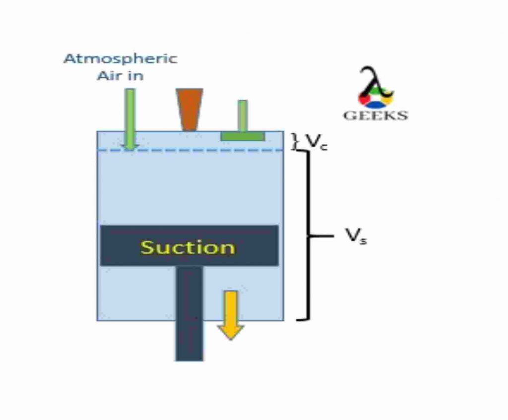
The process starts with sucking the atmospheric air into the cylinder, then the compression process takes place, resulting in increased pressure and temperature of the air.

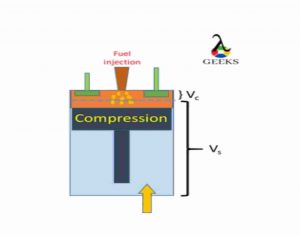
At the end of this stage, the air is at a high temperature and high pressure, just a bit before the end of the compression stage, the fuel is added through the fuel injector. as the fuel comes in contact with this high-temperature, high-pressure air, it self-ignites, and the combustion stage occurs.

Combustion of enriching fuel results in the generation of power, which results in the power stroke, i.e., the piston is pushed back with high, resulting in work output than the last stage, i.e., exhaustion takes place, to let out the burnt gas in the cylinder.

And then, the process is repeated.

To get continuous output, we are required to arrange the number of cylinders rather than just one.

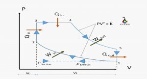
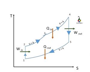
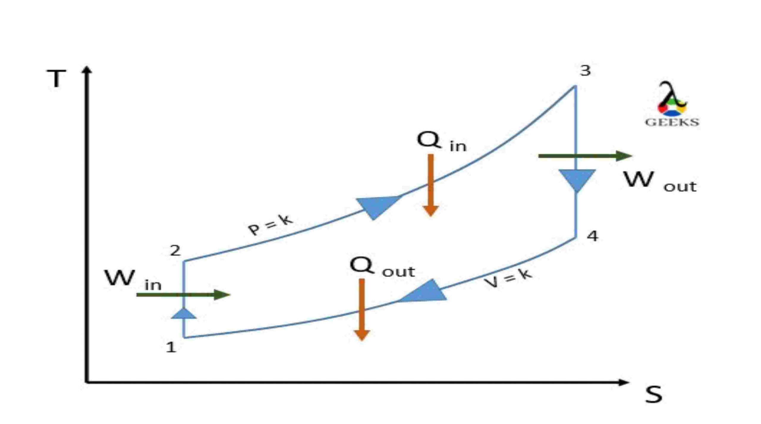
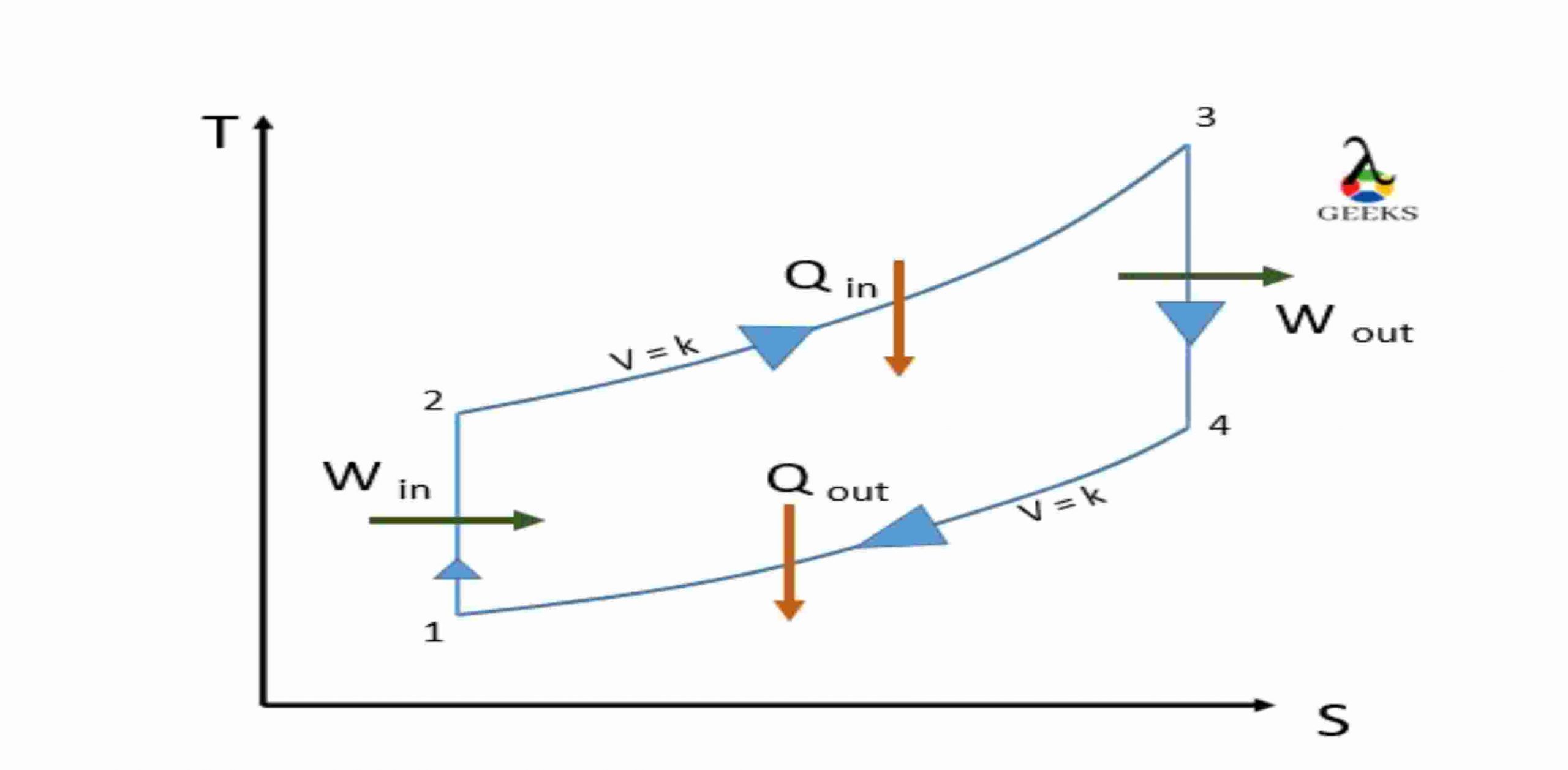
Diesel cycle pv diagram | diesel cycle ts | diesel cycle pv and ts diagram | diesel cycle pv ts diagram | diesel cycle diagram

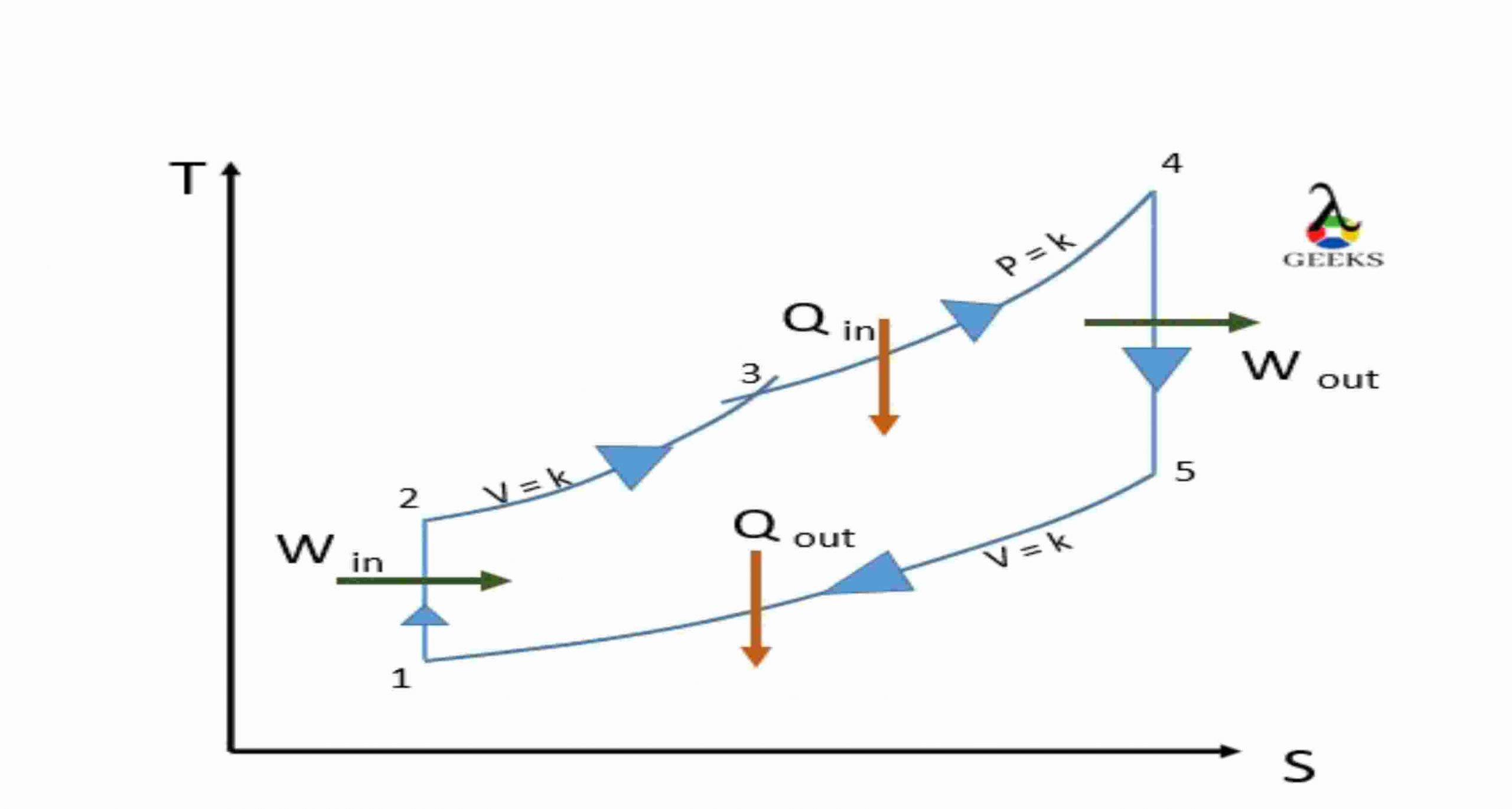
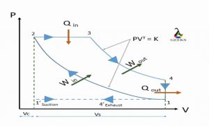
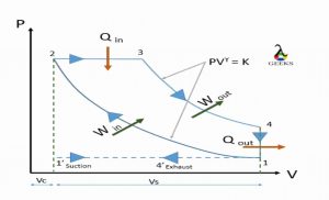
Diesel cycle
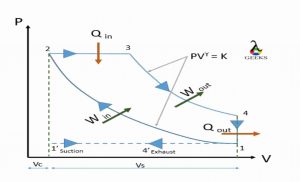
PV daigram
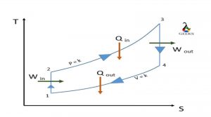
TS daigram
TS daigram

Processes:

1’- 1: suction of Atmospheric air

Atmospheric air is sucked into the cylinder to carry out the compression process. when piston travel in downward direction towards Bottom Dead Center.

system acts as open system.

1-2: Isentropic Adiabatic compression

The piston travels from Bottom of the cylinder (BDC) to Top of the cylinder (TDC), compressing the air adiabatically, keeping entropy constant. No heat heat interaction is taken under consideration. System acts as a closed system.

2-3: Constant pressure heat addition

just before end of compression stroke, fuel is injected with the help of a fuel manifold, and this mixture of fuel with high temperature and high-pressure air makes the fuel to self-ignite (Unlike the petrol engine, Diesel engine doesn’t have spark plug to help combustion process, it has fuel injector is placed to insert the fuel) and releasing the heat in high amount, causing the force at the head of the piston making it move to BDC. This process is carried out under constant pressure. (Actual process is not possible under constant pressure). At a point it acts as a open system as fuel enters the system.

3-4: Isentropic Adiabatic expansion

The piston travels from Top of the cylinder (TDC) to Bottom of the cylinder (BDC) due to the force result of the combustion. And expansion takes place at constant entropy. No heat interaction is taken under consideration.

system acts as a closed system.

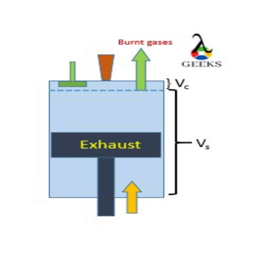
4-1-4’: Exhaust of burnt gases

The burnt gas is let out from the exhaust port to make a start for the next cycle. system again acts a open system. we assume the exhaustion process take place at constant volume.

Diesel cycle analysis

1. The piston in the reciprocating engine moves from Top Dead Center to Bottom Dead Center, causing low pressure inside the cylinder. At this point, the inlet port is let open allowing fresh atmospheric oxygen-rich air to enter into the cylinder. The reciprocating system acts as the open system while this process, allowing mass to enter the system.

this process is carried out at a constant pressure (1′-1)

At the end of the suction, the port is closed, and the the system acts as a closed system.

1 1

2. The ideal cycle process start when the piston reaches the Bottom Dead Center and starts moving towards Top dead Center.

The reciprocating engine plays as a closed-system. The air inside the cylinder is compressed by the piston. the compression is isentropic-adiabatic compression. (No entropy generation and no heat consideration). As a result of compression, the air reaches high pressure and high temperature.

Before the piston reaches the Top of the cylinder (TDC), the fuel is through the manifold in to the cylinder.

This introduced fuel is in spray form; as the fuel comes in contact with the high pressure and high-temperature environment, it gets self-ignited (No need of spark-plug), causing energy release (Chemical energy is transformed into heat energy).

2.1 1
2.2 2

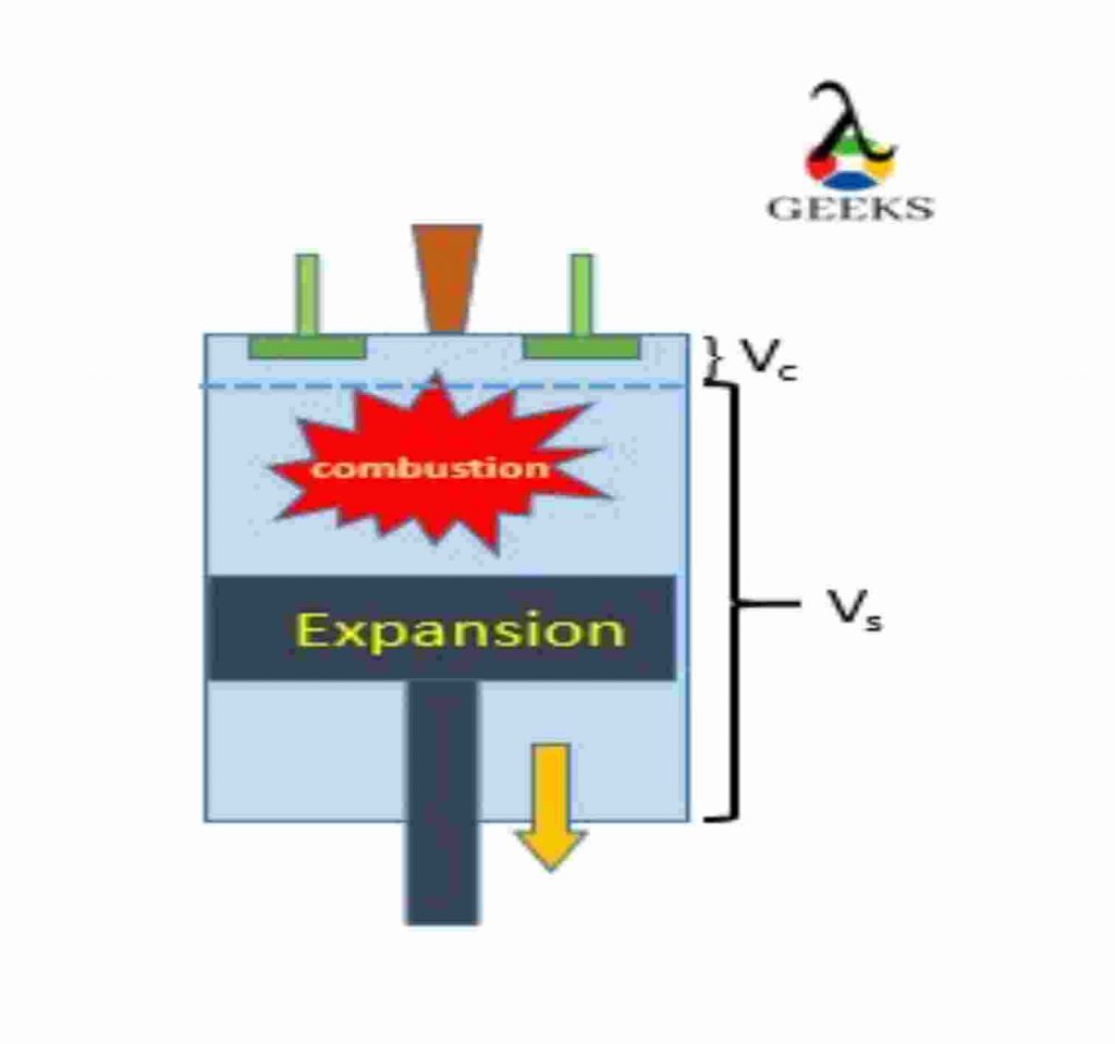
3. The actual power generation takes place at this process; the high force is generated when the combustion takes place, and it forces the piston from Top Dead Center to Bottom Dead Center. The expansion process takes place at this point.

The force is transmitted to run the crankshaft and generate the mechanical energy from the heat energy.

(This stroke is also known as power stroke, in four stroke engine we get one power stroke for every two rotation while in Two stroke we get power power stroke for each rotation.)

3

4. Burnt gas (residue) must be let out of the cylinder, hence that work is done by piston by
moving from BDC to TDC

And the one cycle of is completed.

(If reciprocating engine is four stroke each operation take place separately, while for two stoke two operations are performed simultaneously. )

4

Diesel cycle derivation| diesel cycle formula

Heat Rejected:

heat\\ rejected.\\ Q_{2}=\\ Q_{4-1} =\\ m\\ Cv\\ (T_4-T_1)

Work output:

W_{net}=Q_{net}= Q_1-Q_2

W_{net}= Q_{2-3} -Q_{4-1}

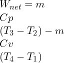
W_{net}=m\\ Cp\\ (T_3-T_2)-m\\ Cv\\ (T_4-T_1)

Compression ratio

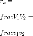
r_{k}=\\ \\frac{V_1}{V_2}=\\ \\frac{v_1}{v_2}

Expansion Ratio

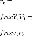
r_{e}=\\ \\frac{V_4}{V_3}=\\ \\frac{v_4}{v_3}

Cut-off ratio:

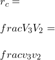
r_{c}=\\ \\frac{V_3}{V_2}=\\ \\frac{v_3}{v_2}

we can corelate the above equation in form as below:

Compression ration can be define as product of expansion ration and cut-off ratio.

r_{k}=\\ r_e\\times r_c

Let us see derivation of each individual process:

Process 3-4:

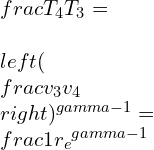
\\frac{T_4}{T_3}=\\ \\left ( \\frac{v_3}{v_4} \\right )^{\\gamma -1}=\\frac{1}{{r_e}^{\\gamma -1}}

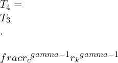
T_4=\\ T_3\\ .\\ \\frac{{r_c}^{\\gamma -1}}{{r_k}^{\\gamma -1}}

Process 2-3:

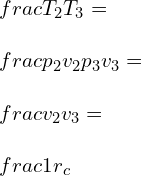
\\frac{T_2}{T_3} =\\ \\frac{p_2 v_2}{p_3v_{3}}=\\ \\frac{v_2}{v_3}=\\ \\frac{1}{r_c}

T_2=\\ T_3\\ .\\ \\frac{1}{r_c}

Process 1-2:

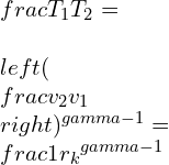
\\frac{T_1}{T_2}=\\ \\left ( \\frac{v_2}{v_1} \\right )^{\\gamma -1}=\\frac{1}{{r_k}^{\\gamma -1}}

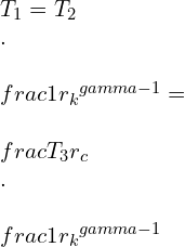
T_1=T_2\\ .\\ \\frac{1}{{r_k}^{\\gamma -1}}=\\ \\frac{T_3}{r_c}\\ .\\ \\frac{1}{{r_k}^{\\gamma -1}}

we will further use this temperature values to get efficiency equation.

The efficiency of diesel cycle derivation | diesel cycle efficiency | diesel cycle efficiency derivation | air standard efficiency of diesel cycle | diesel cycle efficiency formula | derivation of diesel cycle efficiency | thermal efficiency of diesel cycle

Efficiency

Efficiency=\\ \\frac{Work\\ output}{Work\\ input}

\\eta =\\ \\frac{W_{net}}{Q_{in}}

\\eta =\\ \\frac{Q_1-Q_2}{Q_{1}}

\\eta =\\1- \\frac{Q_2}{Q_{1}}

\\eta =\\1- \\frac{m\\ Cv\\ (T_4-T_1))}{m\\ Cp\\ (T_3-T_2)}

\\eta =\\1- \\frac{T_4-T_1}{\\gamma \\ (T_3-T_2)}

By substituting  T1,T2,T3 in eff enq

\\eta =\\ 1\\ -\\ \\frac{T_3.\\frac{{r_c}^{\\gamma -1}}{{r_k}^{\\gamma -1}}.\\frac{T_3}{r_c}\\frac{1}{{r_k}^{\\gamma -1}}}{\\gamma \\left ( T_3-T_3\\ . \\frac{1}{r_c}\\right )}

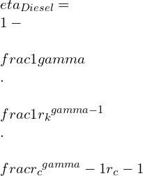
\\eta _{Diesel}=\\ 1-\\ \\frac{1}{\\gamma }\\ .\\ \\frac{1}{{r_k}^{\\gamma -1}}\\ .\\ \\frac{{r_c}^{\\gamma }-1}{{r_c}-1}

Compression ratio of diesel cycle

The compression ratio of the diesel cycle is the ratio of the maximum volume available in the cylinder when the piston is at Bottom Dead Center-(BDC) to the minimum volume available when the piston is at TDC.

Compression\\ ratio= \\frac{Total\\ volume}{clearance\\ volume}

r_{k}=\\ \\frac{V_1}{V_2}=\\ \\frac{v_1}{v_2}

Mean effective pressure formula for diesel cycle

Mean effective pressure is the ratio of network-done to the swept-volume

MEP = \\frac{net work-output}{Swept\\ volume}

MEP = \\frac{m\\ Cp\\ (T_3-T_2)-m\\ Cv\\ (T_4-T_1)}{v_1-v_2}

Cut off ratio in diesel cycle

The cut-off ratio in the diesel cycle is defined as the ratio of volume after combustion to the volume before combustion.

Cut-off\\ ratio= \\frac{Compression\\ ratio}{Expansion\\ ratio}

r_{c}=\\ \\frac{V_3}{V_2}=\\ \\frac{v_3}{v_2}

Semi diesel cycle

Semi diesel cycle, also known as the dual cycle, is the combination of otto and diesel cycles.

In this semi diesel/ dual cycle the heat is added at both constant volume and constants pressure.

( there is simple modification only, the part of heat added is under the constant volume and a remaining part of heat is added at constant pressure)

dual pv 2
P-V diagram

process:

Dual Ts 2
T-S diagram

1-2: Isentropic Adiabatic compression:

Air is compressed adiabatically, keep entropy constant and no heat interaction.

2-3: Constant volume Heat addition:

just before the end of compression stroke , that is piston reaches the TDC of cylinder, the fuel is
added and combustion take place at a Isochoric condition, (constant volume).

3-4: Constant pressure Heat addition

A part of combustion is also carried at at constant pressure. and with this heat addition is completed.

4-5: Isentropic Adiabatic expansion

Now, as the high amount of force is generated it pushes piston now and causes the power stroke.

The work output is obtain at this point.

5-6: Constant volume Heat rejection

At the end the burnt gas is let out of the system to make place for fresh supply of air and carry out next cycle.

Two cycle diesel

A two-cycle diesel engine, also known as a two-stroke diesel engine, works similarly to a four-stroke diesel engine. But it gives power stroke for each revolution while a four-stroke engine gives power stroke for two revolutions.

There exists a transfer port inside the cylinder to carry two operations simultaneously.

When the compression takes place, the suction is also taking place.

And when expansion takes place, the input of oxygen-rich air takes place, letting exhaust burn gas out

Simultaneously.

Difference between diesel and otto cycle| diesel vs otto cycle

ParametersDiesel cycleOtto cycle
DefineThe diesel cycle or Ideal diesel cycle is the power-producing cycle where heat addition takes place at constant pressure.The Otto cycle is also the ideal power-generating cycle, where heat addition takes place at Isochoric condition (constant volume.)
T-S diagramTS 1 scaledotto scaled
ProcessTwo isentropic ( 1-2 & 3-4 )
One isobaric heat addition (2-3)
One isochoric heat rejection (4-1)
Two isentropic ( 1-2 & 3-4 )
one isochoric heat addition (2-3)
one isochoric heat rejection (4-1)
Compression ratioThe efficiency of diesel cycle is more as compare to Otto cycle..The efficiency of diesel cycle is less as compare to Otto cycle.
Same compression ratioThe efficiency of diesel cycle is less as compare to Otto cycle.The efficiency of diesel cycle is more as compare to Otto cycle.
Same maximum pressureThe efficiency of diesel cycle is less as compare to Otto cycle.The efficiency of diesel cycle is more as compare to Otto cycle.
ApplicationDiesel cycle is used for Diesel/IC engineOtto cycle is used for Petrol/SI engine

difference between otto cycle diesel cycle and dual cycle

ParametersDiesel cycleOtto cycleDual Cycle
DefineThe diesel cycle or Ideal diesel cycle is the power-producing cycle where heat addition takes place at constant pressure.The Otto cycle is also the ideal power-generating cycle, where heat addition takes place at Isochoric condition (constant volume.)The dual cycle or semi diesel cycle is a combination of the Otto and diesel cycles. In this cycle, the heat is added at both Isochoric condition (constant volume) and isobaric condition (constants pressure.)
T-S diagramTS 1 scaledotto scaledDual Ts scaled
ProcessTwo isentropic (1-2&3-4 )
One isobaric heat addition (2-3)
One isochoric heat rejection (4-1)
Two isentropic (1-2 & 3-4 ) one isochoric heat addition (2-3)
one isochoric heat rejection ( 4-1)
Two isentropic ( 1-2 & 4-5 )
One isochoric heat addition(2-3)
One isobaric heat addition (3-4)
One isochoric heat rejection (4-1)
Compression ratioCompression ratio is 15-20Compression ratio is 8-10Compression ratio is 14
Same compression ratioThe Efficiency of diesel cycle is more as compare to The Otto cycle.The Efficiency of diesel cycle is less as compare to The Otto cycle.The efficiency is between
both the cycles (i.e Otto and
Diesel)
Same maximum pressureThe Efficiency of diesel cycle is less as compare to The Otto cycle.The Efficiency of diesel cycle is more as compare to The Otto cycle.The efficiency is between
both the cycles (i.e Otto and
Diesel)
ApplicationDiesel cycle is used for Diesel/IC engineOtto cycle is used for Petrol/SI engineDual cycle is used for IC engine.

Application of diesel cycle

Diesel-Internal Combustion engines:

  • Automobiles Engines
  • Ships and marine applications
  • Transport vehicles.
  • machinery used for agriculture
  • construction equipment and machines
  • military and defense
  • HVAC
  • Power generation

Advantages of diesel engine

New advanced have made diesel engine performance quite good, it is less noisy and has low maintenance cost.

Diesel engine are reliable and robust.

No need of spark-plug , fuel used is of self-igniting nature.

fuel cost is also low as compare to petrol.

diesel cycle sample problems | diesel cycle example | diesel cycle example problems

Q1.With compression ratio of 14, and cut-off at 6% what will be the efficiency of the diesel cycle?

Ans=

Pv 3

r_k=\\frac{v_1}{v_2}=14

v_3-v_2=0.06(v_1-v_2)

v_3-v_2=0.06(14v_2-v_2)

v_3-v_2=0.78v_2

v_3=1.78v_2

Cut-off ratio, r_c=\\frac{v_3}{v_2}=1.78

\\eta _{Diesel}=\\ 1-\\ \\frac{1}{\\gamma }\\ .\\ \\frac{1}{{r_k}^{\\gamma -1}}\\ .\\ \\frac{{r_c}^{\\gamma }-1}{{r_c}-1}

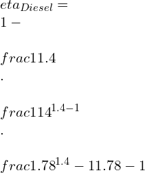
\\eta _{Diesel}=\\ 1-\\ \\frac{1}{1.4}\\ .\\ \\frac{1}{{14}^{\\1.4 -1}}\\ .\\ \\frac{{1.78}^{1.4 }-1}{{1.78}-1}

\\eta _{Diesel}=\\ 1-0.248.\\frac{1.24}{0.78}=0.605

\\eta _{Diesel}=60.5%

Q2. Standard diesel cycle with compression ratio of 16, Heat is added at constant pressure of 0.1 MPa. Compression begins at 15 deg Celsius and reaches 1480 deg Celsius at end of combustion.

Find the following:

1. Cut-off ratio

2. Heat added/kg of air

3. Efficiency

4. MEP

Ans=

r_k=\\frac{v_1}{v_2}=16

T1= 273 + 15 = 288K


p1= 0.1 MPa = 100 KN/m2


T3 = 1480 + 273 = 1735K

Pv 4
TS 2

\\frac{T_2}{T_1}= \\left ( \\frac{v_1}{v_2} \\right )^{\\gamma -1}=(16)^{0.4}=3.03

T_2= 288 \\times 3.03= 873K

\\frac{p_2v_2}{T_2}=\\frac{p_3v_3}{T_3}

(a) Cut-off ratio:
r_c=\\frac{v_3}{v_2}=\\frac{T_3}{T_2}=\\frac{1753}{273}=2.01

(b) Heat Supplied:
Q_1=Cp\\ (T_3-T_2)

Q_1=1.005\\ (1753-873)

Q_1=884.4 kJ/kg

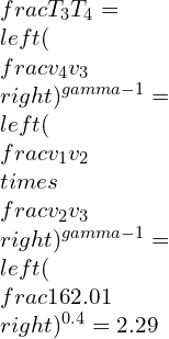
\\frac{T_3}{T_4}=\\left ( \\frac{v_4}{v_3} \\right )^{\\gamma -1}=\\left ( \\frac{v_1}{v_2}\\times \\frac{v_2}{v_3} \\right )^{\\gamma -1}=\\left ( \\frac{16}{2.01} \\right )^{0.4}=2.29

T_4=\\frac{1753}{2.29}=766\\ K

heat rjected,

Q_2=Cv\\ (T_4-T_1)

Q_2=0.718\\ (766-288)=343.2kJ/kg

(c) Cycle Efficiency = 1-\\frac{Q_2}{Q_1}

\\eta =1-\\frac{343.2}{884.4}=0.612=61.2%

Also can be determined by;

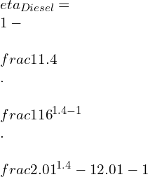
\\eta _{Diesel}=\\ 1-\\ \\frac{1}{\\gamma }\\ .\\ \\frac{1}{{r_k}^{\\gamma -1}}\\ .\\ \\frac{{r_c}^{\\gamma }-1}{{r_c}-1}

\\eta _{Diesel}=\\ 1-\\ \\frac{1}{1.4}\\ .\\ \\frac{1}{{16}^{1.4 -1}}\\ .\\ \\frac{{2.01}^{1.4 }-1}{{2.01}-1}

\\eta _{Diesel}=1-\\frac{1}{1.4}.\\frac{1}{3.03}.1.64

\\eta _{Diesel}=0.612= 61.2%

W_{net}=Q_1\\times \\eta _{cycle}

W_{net}=884.4\\times 0.612\\times = 541.3 kJ/kg

v_1=\\frac{RT_1}{p_1}=\\frac{0.287\\times 288}{100}=0.827m^{3}/kg

v_2=\\frac{0.827}{16}=0.052\\ m^3/kg

\\therefore\\ v_1-v_2=0.827-0.052=0.775\\ m^3/kg

(d) mean effective pressure (MEP):

MEP=\\frac{W_{net}}{v_1-v_2}=\\frac{541.3}{0.775}=698.45 kPa

FAQs

Otto cycle vs. diesel cycle efficiency

At the same compression ratio: efficiency of diesel cycle is more as compare to Otto cycle.
At same maximum pressure: efficiency of diesel cycle is less more as compare to Otto cycle.

Diesel cycle chart

1’- 1: suction of Atmospheric air

1-2: Adiabatic compression

2-3: Constant pressure heat addition (fuel injection & combustion)

3-4: Adiabatic expansion

4-1-4’: Exhaust of burnt gases

Pv 2

When the efficiency of diesel cycle approaches the Otto cycle efficiency

The efficiency of the diesel cycle approaches the Otto cycle efficiency when the cut-off ratio approaches zero.

Why are engines that use the Diesel cycle able to produce more torque than engines using the Otto cycle

The diesel engine has a greater compression ratio than the Otto cycle engine.

Combustion in the diesel cycle takes place at TDC at the end of the compression stroke and causes the piston to move downward. While in the Otto cycle, engine combustion takes place when the piston is slightly moving towards BDC and contributes to acquire speed.

Diesel fuel is more dense than petrol (used in the Otto cycle), which generates more energy in terms of power.

Also, the size factor does matter; the stroke length and Bore diameter of the Diesel engine is greater than the Otto cycle engine.

Why cant petrol be used in a diesel cycle.

The volatility of petrol is much higher than Diesel; even before completion of the compression stroke, the high pressure will evaporate the fuel.

Hence petrol will ignite in the uncontrolled matter, causing detonation and misfiring.

it will result in damaging of the cylinder hence one should never start the engine if such incidence take place. It is advisable to contact the concern person to remove the petrol form the engine.

Why is the diesel cycle only applicable to large low-speed engines

Diesel cycle uses fuel which is more viscous and power produce in terms of the torques is more.

when we need application of high load we cant use petrol engine as the efficiency will be less for loading condition and will use more fuel.

hence the diesel engine will be beneficial here where the power produce is more at low speed.

for more article related to Mechanical Engineering visit our website.

Carnot Cycle: 21 Important Facts You Should Know

1 1 300x200 1

CARNOT CYCLE

Nicolas Léonard Sadi-Carnot, a French mechanical engineer, Scientist, and physicist, introduced a heat engine known as the Carnot Engine in the book “Reflections on the Motive Power of Fire. It leads to being the foundation of the Second law of thermodynamics and entropy. Carnot’s contribution holds a remark which gave him the title of “Father of Thermodynamics.

Table of Content

Carnot cycle in thermodynamics | working principle of Carnot cycle | ideal Carnot cycle | Carnot cycle thermodynamics | Carnot cycle definition | Carnot cycle working principle | air standard Carnot cycle| Carnot cycle reversible.

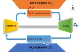
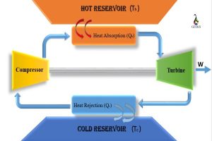
Carnot cycle is the theoretical cycle that works under two thermal reservoirs (Th & Tc) undergoing compression and expansion simultaneously.

It consists of four reversible processes, of which two are isothermal, i.e., constant temperature followed alternately by two reversible adiabatic processes.

The working medium used in the Sadi-Carnot cycle is atmospheric air. 

Heat addition and Heat rejection are carried out at a constant temperature, but no phase change is considered.

Carnot cycle
Carnot cycle

Importance of Carnot Cycle

The invention of the Carnot cycle was a very big step in the history of thermodynamics. First, it gave theoretical working of heat engine used for the design of an actual heat engine. Then, reversing the cycle, we get refrigeration effect (mentioned below). 

Carnot cycle work between two thermal reservoirs (Th & Tc), and its efficiency depends only on this temperature and doesn’t depend on the fluid type. That is Carnot’s cycle efficiency is fluid independent.

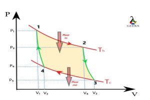
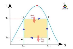
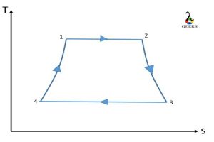
Carnot cycle pv diagram | Carnot cycle ts diagram | pv and ts diagram of Carnot cycle | Carnot cycle pv ts | Carnot cycle graph | Carnot cycle pv diagram explained | Carnot cycle ts diagram explained

2 1 2
P-V Carnot
3 3
T-S Carnot

Process 1-2: Isothermal expansion

In this process, the air is expanded with constant temperature while gaining heat. 

That is, constant temperature heat addition takes place. 

Expansion => pressure ↑ => results Temperature ↓

Heat Addition => Temperature ↑

Hence Temperature remain constant 

Process 2-3: Reversible adiabatic expansion 

In this process, the air is expanded, keeping entropy constant and with no heat interaction. 

That is no change in entropy, and the system is insulated

We get work output in this process

Process 3-4: isothermal compression

In this process, the air is compressed with a constant temperature while losing heat.

That is, constant temperature heat rejection takes place.

Compression => pressure ↓ => results: Temperature ↑

Heat Addition => Temperature ↓

Hence Temperature remain constant 

Process 4-1: Reversible Adiabatic Compression

In this process, the air is compressed, keeping entropy constant and no heat interaction. 

That is no change in entropy, and the system is insulated

We supply work in this process

Carnot cycle consists of | Carnot cycle diagram | Carnot cycle steps | 4 stages of Carnot cycle | Carnot cycle work| isothermal expansion in Carnot cycle| Carnot cycle experiment

Process 1-2:

The expansion process is carried out where temperature Th is kept constant, and heat (Qh) is added to the system. The temperature is kept constant as follows: The rise in temperature due to heat addition is compensated by the decrease in temperature due to expansion. 

Hence the process carried out results as constant temperature as the start and end temperature of the process is same.

Isothermal expansion

Process 2-3:

As we can see, the process is reversible (change in internal energy = 0) Adiabatic (only work transfer, no heat involvement), the expansion carried out just results in a change in temperature (from Th to Tc), keeping the entropy constant. 

System act as being insulated for this part of the expansion. 

Sensible cooling is taking place.

Reversible Adiabatic expansion

Process3-4:

The compression process is carried out where temperature Tc is kept constant, and heat is removed from the system. The temperature is kept constant as follows: The decrease in temperature due to heat rejection is compensated by the increase in temperature due to compression. 

Hence the process carried out results as constant temperature as the start and end temperature of the process is same.

Similar to processes 1-2 but in the exact opposite manner.

Isothermal Compression

Process 4-1:

As we can see, the process is reversible (change in internal energy = 0) Adiabatic (only work transfer, no heat involvement), the compression carried out just results in a change in temperature (from Tc to Th), keeping the entropy constant. 

System act as being insulated for this part of the compression. 

Sensible heating is taking place.

6.41
Reversible Adiabatic Compression

Carnot cycle equations| Carnot cycle derivation

Process 1-2: Isothermal expansion

as Th is kept constant. [Internal energy (du) = 0] ( PV = K)

Qh = W ,

therefore, W = int_{V_{1}}^{V_{2}}PdV

P = frac{K}{V}

W = Kint_{V_{1}}^{V_{2}}frac{dV}{V}

W = P_{1}V_{1}int_{V_{1}}^{V_{2}}frac{dV}{V}

W = P_{1}V_{1}left ( lnfrac{V_{2}}{V_{1}} right )

W = mRT_{h}left ( lnfrac{V_{2}}{V_{1}} right )

Process 2-3: Reversible adiabatic expansion

PV^{gamma } = K

W = int_{V_{2}}^{V_{3}}PdV

PV^{gamma } = K

therefore W = Kint_{V_{2}}^{V_{3}}frac{dV}{V^{gamma }}

W = P_{2}V^{gamma }_{2}int_{V_{2}}^{V_{3}}frac{dV}{V^{gamma }}

W = P_{2}V^{gamma }_{2}int_{V_{2}}^{V_{3}}{V^{-gamma }{dV}}

W = Kint_{V_{2}}^{V_{3}}{V^{-gamma }{dV}}

W = K left [ frac{V^{1-gamma }}{1-gamma } right ]_{2}^{3}

PV^{gamma } = K = P_{2}V_{2}^{gamma } = P_{_{3}}V_{3}^{gamma }

W=left [ frac{P_{3}V^{gamma }_{3}V_{3}^{1-gamma }-P_{2}V^{gamma }_{2}V_{2}^{1-gamma }}{1-gamma } right ]

W=left [ frac{P_{3}V_{3}-P_{2}V_{2}}{1-gamma } right ]

Also

P_{2}V_{2}^{gamma } = P_{_{3}}V_{3}^{gamma } = K

left [ frac{T_{2}}{T_{3}} right ] =left [ frac{V_{3}}{V_{2}} right ]^{gamma -1}

As process is Adiabatic , Q = 0
therefore W = -du

Process 3-4: isothermal compression

similar to process 1-2, we can get

as Tc is kept constant. [Internal energy (du) = 0] ( PV = K)

Qc = W ,

W = P_{3}V_{3}left ( lnfrac{V_{3}}{V_{4}} right )

W = mRT_{c}left ( lnfrac{V_{3}}{V_{4}} right )

Process 4-1: Reversible Adiabatic Compression

similar to process 2-3, we can get

W=left [ frac{P_{1}V_{1}-P_{4}V_{4}}{1-gamma } right ]

P_{4}V_{4}^{gamma } = P_{{1}}V{1}^{gamma } = K

left [ frac{T_{1}}{T_{4}} right ] =left [ frac{V_{4}}{V_{1}} right ]^{gamma -1}

Carnot cycle work done derivation

According to first law of thermodynamics

Wnet = Qtotal

Wnet = Qh-Qc

Wnet = mRT_{h}left ( lnfrac{V_{2}}{V_{1}} right ) - mRT_{c}left ( lnfrac{V_{3}}{V_{4}} right )

Derivation of entropy from carnot cycle | entropy change in carnot cycle | change in entropy carnot cycle | derivation of entropy from carnot cycle | entropy change in carnot cycle

To make cycle reversible, Change in entropy is zero (du = 0).

ds = frac{delta Q}{T}  +  S_{gen}

S_{gen}  = 0 ,  for  reversible  process

that means,

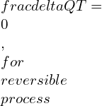
frac{delta Q}{T}= 0 ,  for  reversible  process

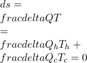
ds = frac{delta Q}{T}  = frac{delta Q_h}{T_h}+ frac{delta Q_c}{T_c} = 0

For process :1-2

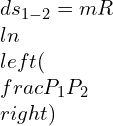
ds_{1-2} = frac{mR T_{h} lnleft ( frac{P_{1}}{P_{2}} right )}{T_h}

ds_{1-2} = m R  lnleft ( frac{P_{1}}{P_{2}} right )

For process :1-2

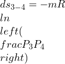
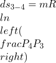
ds_{3-4} =- frac{mR T_{c} lnleft ( frac{P_{3}}{P_{4}} right )}{T_c}

ds_{3-4} = frac{mR T_{c} lnleft ( frac{P_{4}}{P_{3}} right )}{T_c}

ds_{3-4} = - m R  lnleft ( frac{P_{3}}{P_{4}} right )

ds_{3-4} =  m R  lnleft ( frac{P_{4}}{P_{3}} right )

d_s = ds_{1-2} + ds_{3-4} = 0

carnot cycle efficiency| carnot cycle efficiency calculation| carnot cycle efficiency equation| carnot cycle efficiency formula | carnot cycle efficiency proof | carnot cycle maximum efficiency | carnot cycle efficiency is maximum when | maximum efficiency of carnot cycle

Carnot cycle efficiency has maximum efficiency considering the Th as the hot reservoir and Tc as a cold reservoir to eliminate any losses.

It is a ratio of Amount of work done by the Heat engine to the Amount of  heat required by the heat engine.

mathbf{eta = frac{Net work done by Heat engine }{heat absorbed by heat engine}}

eta = frac{Q_{h}- Q_{c}}{Q_{h}}

eta =1- frac{ Q_{c}}{Q_{h}}

eta =1-  frac{mRT_{c}left ( lnfrac{V_{3}}{V_{4}} right )}{ mRT_{h}left ( lnfrac{V_{2}}{V_{1}} right )}

As from above equation we know,

left [ frac{T_{1}}{T_{4}} right ] =left [ frac{V_{4}}{V_{1}} right ]^{gamma -1}

&

left [ frac{T_{2}}{T_{3}} right ] =left [ frac{V_{3}}{V_{2}} right ]^{gamma -1}

but
left T_1 = T_2 = T_h
left T_3 = T_4 = T_c

frac{V_{2}}{V_{1}} = frac{V_{3}}{V_{4}}

eta =1- frac{T_{c}}{T_{h}}

We can get an efficiency of 100% if we get to reject heat at 0 k (Tc = 0)

Carnot holds a maximum efficiency of all the engines performing under the same thermal reservoir as Carnot cycle work reversible, making assumptions of eliminating all the losses and making cycle a frictionless cycle, which is never possible in practice.

Hence all practical cycles will have efficiency less than Carnot efficiency.

Reverse carnot cycle | the reversed carnot cycle | reversed carnot refrigeration cycle

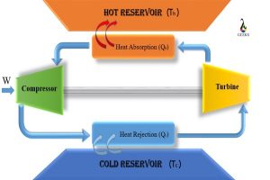
Reverse Carnot cycle:

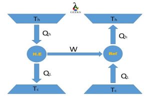
As all the processes carried out in the Carnot cycle are reversible, We can make it work in a reverse manner, i.e., to take heat from the lower temperature body and dumped to a higher temperature body, making it a refrigeration cycle.

.

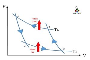
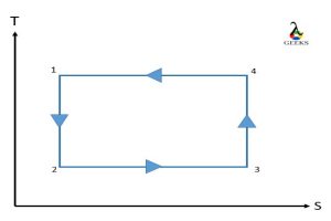
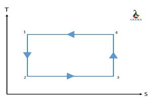
Reversed Carnot cycle
P-V Reversed Carnot cycle
T-S Reversed Carnot cycle

Process 1-2: Reversible adiabatic expansion 

In this process, the air is expanded, temperature is reduced to Tc, keeping entropy constant and with no heat interaction. 

That is no change in entropy, and the system is insulated

Process 2-3: Isothermal expansion

In this process, the air is expanded with constant temperature while gaining heat. The heat is gain from the Heat sink at low temperature. Heat addition takes place while keep temperature(Tc) is kept constant. 

Process 3-4: Reversible Adiabatic Compression

In this process, the air is compressed, rising the temperature to Th, keeping entropy constant and no heat interaction. 

That is no change in entropy, and the system is insulated

Process 4-1: isothermal compression

In this process, the air is compressed with a constant temperature while losing heat. Heat is rejected to the hot reservoir. Heat rejection takes place while keep temperature(Th) is kept constant. 

Reverse carnot cycle efficiency

The efficiency of reversed Carnot cycle is termed as Coefficient of performance.

COP is defined as the ratio of the desired output to the energy supplied.

COP = frac{Desired Output}{Energy Supplied}

Carnot refrigeration cycle| carnot refrigeration cycle efficiency | coefficient of performance carnot refrigeration cycle | carnot cycle refrigerator efficiency

The refrigeration cycle works on reversed Carnot cycle. The main objective of this cycle is to reduce the temperature of the heat source/ hot reservoir.

COP = frac{Desired Output}{Energy Supplied}=frac{Q_{c}}{W^{_{net}}}

COP =frac{Q_c}{Q_h-Q_c}=frac{Q_c}{Q_h}-1

 Application: Air- conditioning, refrigeration system

Carnot cycle heat pump

The heat pump works on reversed Carnot cycle. The main objective of the Heat pump is to transmit heat from one body to another, most from lower temperature body to higher temperature body with the help of supplied work.

COP = frac{Desired Output}{Energy Supplied}=frac{Q_{c}}{W^{_{net}}}

COP = frac{Desired Output}{Energy Supplied}=frac{Q_{h}}{W^{_{net}}}

COP =frac{Q_h}{Q_h-Q_c}=1-frac{Q_h}{Q_c}

COP_{HP}=COP_{REF}+1

Comparison of carnot and rankine cycle | difference between carnot and rankine cycle

 Comparison:

Parameter Carnot cycle Rankine cycle
definition Carnot cycle is an ideal thermodynamic cycle that works under two thermal reservoirs. Rankine cycle is a practical cycle of the steam engine and turbine
T-S diagram 11. 5
Heat addition and rejection Heat addition and rejection take place at a constant temperature.(isothermal)         Heat addition and rejection take place at constant pressure (isobaric)
Working medium The working medium in Carnot is atmospheric air. Single-phase system The working medium in Carnot is water/steam. Handles two phases
Efficiency Carnot efficiency is maximum among all cycles. Rankine efficiency is less than Carnot.
application Carnot cycle is used for designing of heat engine. Rankine cycle is used for designing of steam engine/turbine.
Comparison Carnot Vs Rankine

Difference between otto cycle and carnot cycle

Parameter Carnot cycle Otto Cycle
definition Carnot cycle is an ideal thermodynamic cycle that works under two thermal reservoirs. Otto cycle is an ideal thermodynamic combustion cycle.
T-s diagram 11. 4
Processes Two isothermal and two Isentropic Two isochoric and two isentropic.
Heat addition and rejection Heat addition and rejection take place at a constant temperature.(isothermal) Heat is produced at constant volume and rejected at the exhaust. No external heat source is required. It produces heat by chemical processes that are the combustion of a petrol air mixture with help spark plug at high pressure.
Working medium The working medium in Carnot is atmospheric air. Petrol and air mixture is used.
Efficiency Carnot efficiency is maximum among all cycles. Otto cycle has Less efficiency than Carnot cycle.
application Carnot cycle is used for designing of heat engine. Otto cycle is used for internal combustion SI engine.
Comparison Carnot Vs Otto

Carnot cycle irreversible

When the Carnot cycle runs on Adiabatic and not on reversible adiabatic, it comes under the category of irreversible Carnot cycle.

Entropy is not maintained constant in Process 2-3 and 4-1, (ds is not equal to zero)

as shown below:

Irreversible Carnot Cycle

Work produce under irreversible cycle is comparatively less than reversible Carnot cycle

Hence, the Efficiency of the irreversible Carnot cycle is less than the reversible Carnot cycle.

Why Carnot cycle is reversible

According to Carnot, the Carnot cycle is a theoretical cycle that provides maximum efficiency. To get this maximum efficiency, we must eliminate all the losses and consider the system reversible.

If we consider any losses, the cycle will fall under the irreversible category and would not provide maximum efficiency.

Carnot cycle volume ratio

left [ frac{T_{1}}{T_{4}} right ] =left [ frac{V_{4}}{V_{1}} right ]^{gamma -1}
&

left [ frac{T_{2}}{T_{3}} right ] =left [ frac{V_{3}}{V_{2}} right ]^{gamma -1}

but
left T_1 = T_2 = T_h

left T_3 = T_4 = T_c

frac{V_{2}}{V_{1}} = frac{V_{3}}{V_{4}}

Hence the volume ratio is maintain constant.

Advantages of carnot cycle

  • Carnot cycle is an ideal cycle that gives maximum efficiency among all the cycle available.
  • Carnot cycle helps in designing the actual Engine to get maximum output.
  • It helps to decide the possibility of any cycle to build. As long as the Engine maintains efficiency less than Carnot, the Engine is possible; otherwise, it is not.

Disadvantages of Carnot cycle

  • It is impossible to supply heat and reject the heat at a constant temperature without phase change in the working material.
  • It is impossible to construct a reciprocating heat engine to travel a piston at a very slow speed from the beginning of the expansion to the middle to satisfy isothermal expansion and then very rapid to help the reversible adiabatic process.

Why Carnot cycle is not used in power plant

Carnot cycle has isothermal to adiabatic transmission. Now to carry out isothermal, we have to either make the process very slow or deal with phase change. Next is reversible adiabatic, which must be carried out quickly to avoid heat interaction.

Hence making the system difficult to construct as the half-cycle run very slow and the other half run very fast.

carnot cycle application | carnot cycle example | application of carnot cycle in daily life

Thermal devices like

  • heat pump: to supply heat
  • Refrigerator: to produce cooling effect by removal of heat
  • Steam turbine: to produce power i.e. thermal energy to mechanical energy.
  • Combustion engines: to produce power i.e. thermal energy to mechanical energy.

Carnot vapor cycle | carnot vapour cycle

In Carnot vapor cycle steam is working fluid

Carnot Vapour cycle
Carnot Vapour cycle
Process 1-2: Isothermal expansion Heating of fluid by keeping temperature constant in the boiler.
Process 2-3: Reversible adiabatic expansion  Fluid is expanded isentropically i.e. entropy constant in a turbine.
Process 3-4: isothermal compression Condensation of fluid by keeping temperature constant in the condenser.
Process 4-1: Reversible Adiabatic Compression Fluid is compressed isentropically i.e. entropy constant and brought back to original state.

Its impracticalities:

1) It is not difficult to add or reject at constant temperature from two phase system, since maintaining it at constant temperature will fix up the temperature at saturation value. But limiting the heat rejection or absorption process to the mixed phase fluid will affect the thermal efficiency of the cycle.

2) The reversible adiabatic expansion process can be achieved by a well-designed turbine. But, the quality of the steam will reduce during this process. This is not be favorable as turbines cannot handle steam having more than 10% of liquid.

3) The reversible adiabatic compression process involves the compression of a liquid – vapour mixture to a saturated liquid. It is difficult to control the condensation process so precisely to achieve state 4. It is not possible to design a compressor that will handle mixed phase.

carnot cycle questions | carnot cycle problems | carnot cycle example problems

Q1.) Cyclic heat engine operators between source at 900 K and sink at 380 K. a) what will be the efficiency? b) what will be heat rejection per KW net ouput of the engine?

Ans = given: T_h = 900 k and T_c = 380 k

efficiency =1- frac{T_{c}}{T_{h}}

eta =1- frac{380}{900}

eta =0.5777=55.77 %

b) Heat reject (Qc) per KW net output

eta =frac{W_{net}}{Q_h}

Q_h=frac{W_{net}}{eta }=frac{1}{0.5777}=1.731 KW

Q_c=Q_h-W_{net}=1.731-1=0.731 KW

Heat reject per KW net output = 0.731 KW

Q2.) Carnot engine working at 40% efficiency with heat sink at 360 K. what will be temperature of heat source? If efficiency of the engine is increased to 55%, what will be the effect on temperature of heat source?

Ans = given : eta = 0.4, T_c=360 K

eta =1- frac{T_{c}}{T_{h}}

0.4 =1- frac{360}{T_{h}}

T_h=600 K

If eta = 0.55

0.55 =1- frac{360}{T_{h}}

T_h=800 K

Q3.) A Carnot engine working with 1.5 kJ of heat at 360 K, and rejecting 420 J of heat. What is the temperature at the sink?

Ans = given: Qh=1500 J, Th= 360 K , Qc= 420 J

eta =1- frac{T_{c}}{T_{h}}=1- frac{Q_{c}}{Q_{h}}

frac{T_{c}}{T_{h}}=frac{Q_{c}}{Q_{h}}

frac{T_{c}}{360}=frac{420}{1500}

T_{c}=frac{420}{1500}*360

T_{c}=100.8 K

FAQ

What is a practical application of a Carnot cycle

  • heat pump: to supply heat
  • Refrigerator: to produce cooling effect by removal of heat
  • Steam turbine: to produce power i.e. thermal energy to mechanical energy.
  • Combustion engines: to produce power i.e. thermal energy to mechanical energy.

carnot cycle vs stirling cycle

Stirling, the Carnot cycle’s isentropic compression and isentropic expansion process are substituted by a constant volume regeneration process. The other two methods are the same as the Carnot cycle it isothermal heat addition and rejection.

What is the difference between a Carnot cycle and a reversed Carnot cycle

Simple carnot cycle works as power developing while reversed carnot work as power consuming.

Carnot cycle is used to design heat engine, while reversed cycle is used to design Heat pump and refrigeration system.

Why carnot cycle is more efficient than any other ideal cycles like otto diesel brayton ideal VCR

Carnot cycle work between two thermal reservoirs (Th & Tc), and its efficiency depends only on this temperature and doesn’t depend on the fluid type. That is Carnot’s cycle efficiency is fluid independent.

Carnot holds a maximum efficiency of all the engines performing under the same thermal reservoir as Carnot cycle work reversible, making assumptions of eliminating all the losses and making cycle a frictionless cycle, which is never possible in practice.

What is the net change in entropy during a Carnot cycle

Net change in entropy during a Carnot cycle is zero.

why carnot cycle is not possible

Carnot cycle has isothermal to adiabatic transmission. Now to carry out isothermal, we have to either make the process very slow or deal with phase change.

Next is reversible adiabatic, which must be carried out quickly to avoid heat interaction.

Hence making the system difficult to construct as the half-cycle run very slow and the other half run very fast.

why is the carnot cycle the most efficient

Carnot cycle work between two thermal reservoirs (Th & Tc), and its efficiency depends only on this temperature and doesn’t depend on the fluid type. That is Carnot’s cycle efficiency is fluid independent.

Carnot holds a maximum efficiency of all the engines performing under the same thermal reservoir as Carnot cycle work reversible, making assumptions of eliminating all the losses and making cycle a frictionless cycle, which is never possible in practice.

Why does the Carnot cycle involve only the isothermal and adiabatic process and not other processes like isochoric or isobaric

The main aim of Carnot Cycle is to achieve maximum efficiency, which leads to make system reversible, so to make system reversible no heat interaction process should me maintain, i.e adiabatic process.

And to get maximum work output we use Isothermal process.

How is the Carnot cycle related to a Stirling cycle?

Stirling, the Carnot cycle’s isentropic compression and isentropic expansion process are substituted by a constant volume regeneration process. The other two methods are the same as the Carnot cycle it isothermal heat addition and rejection.

What will happen with efficiency of two Carnot engine works with same source and sink?

Efficiency will be the same, as Carnot cycle efficiency is only dependent on the temperature of the source and sink.

Combination of Carnot cycle and Carnot refrigerator

The work output of Carnot heat engine supplied as work input for Carnot refrigeration system.

Combine cycle.
Combine cycle.

Is it necessary that refrigerators should only work on Carnot cycle?

To get the maximum Coefficient of performance (COP), theoretically we net refrigeration cycle to work on Carnot.

The temperature of two reservoirs of a Carnot engine are increased by same amount How will be the efficiency be affected?

The increase in temperature of both reservoirs in same will tend to decrease in efficiency

Uses of stand in Carnot cycle?

The stand is used to carry out an adiabatic process. It is made up of non-conduction material.

Important results for Carnot engine cycle?

Any number of engines working under the Carnot principle and having the same source and sink will have the same efficiency.

Terminal of Carnot engine?

Carnot engine will consist of: Hot reservoirCold sink Insulating stand.

Definition of insulating stand which is one of the part of Carnot’s engine?

The stand is used to carry out an adiabatic process, and it is made up of non-conduction material.

For more Articles regarding Mechanical & Thermal, do visit our Home page.

Parallel Flow Heat Exchanger: 23 Important Facts

CONTENT

What is parallel flow heat exchanger?

A direct transfer type of heat exchanger in which both hot fluid and cold fluid flow in the same direction to exchange heat energy between them without transfer of any energy from the ambient. 

Parallel flow heat exchanger theory

Heat exchanger is defined as a steady flow adiabatic open system. Flow of both fluids (hot fluid and cold fluid) are in the same direction to exchange heat between. It is a categorized as direct transfer type heat exchanger in which fluids do not have any physical contact between them.  The pressure of both hot and cold fluid remains constant.
The Enthalpy loss of hot fluid is equal to the Enthalpy gain by cold liquid. The variation of temperature between hot fluid and cold fluid in the direction of the flow always decreases.
Screenshot 2021 06 02 at 7.52.59 PM 1
Fig: 1 Flow in parallel flow Heat Exchanger (Image credit: wikimedia)

Where,

Th,in: Temperature of inlet hot fluid

Th,out: Temperature of outlet cooled fluid 

Tc,in: Temperature of inlet cold fluid

Tc,out: Temperature of outlet warm fluid

Advantages of parallel flow heat exchanger

Loss of pressure is very low
It is simple in construction and cheap to build.

Parallel flow plate heat exchanger

A cluster of plates are placed in a systematic manner one above the other for the formation of a series of channels for fluid flow to exchange heat energy between them. The increase in surface area by the plates allows more heat transfer between the two fluids.
File:เครื่องแลกเปลี่ยนความร้อนแบบแผ่น.png
Fig: 2 Plate type heat exchanger (Image credit: wikimedia)

Parallel flow heat exchanger vs counter flow heat exchanger

The variation of temperature between hot fluid and cold fluid with respect to the flow direction is more pronounced in parallel flow heat exchanger. The entropy of parallel flow type heat exchanger is higher as compared to counter type heat exchanger. Counter flow heat exchanger is more efficient than parallel flow heat exchanger. Hence for the same heat transfer rate required in both cases, counter flow heat exchanger occupies lesser heat transfer area or more compact in size than parallel flow heat exchanger.

What is effectiveness of parallel flow heat exchanger?

‘The effectiveness (ϵ) of a heat exchanger is defined as the ratio of the actual heat transfer to the maximum possible heat transfer.’
Actual heat transfer (Q) = mh*Cph*(Th1 – Th2
= mc*Cpc*( Tc2 – Tc1)
Maximum possible heat transfer (Qmax) = Ch(Th1 – Tc1)
image 7

Parallel flow and counter flow heat exchanger experiment

Aim: To determine the effectiveness of the heat exchanger in parallel flow and counterflow.
The experiment setup consists of the following component,
  • Heater
  • Pump
  • Hot water inlet and outlet
  • Cold water inlet and outlet
  • Temperature sensor
  • Flow regulator

Procedure:

First, we have to switch ON the testing apparatus, Then switch ON the heater and set the temperature of the water heater. We have to Wait for the temperature of the water to raised upto the set point. Switch ON the pump for both hot and cold water. Set the mass flow rate of both hot and cold water using a flow regulator knob. All the temperature at inlet and exit are recorded. First, set the heat exchanger in a parallel configuration and note the readings.

Specific capacity of hot fluid: _________

Specific capacity of cold fluid: _________

  1. Adjusted mass flow rate of hot fluid (mh) are recorded
  2. Adjusted mass flow rate of cold fluid (mc) are recorded
  3. Set Inlet temp. of hot fluid are recorded (Th1)
  4. The Outlet temp. of hot fluid  are recorded (Th2)
  5. Inlet temp. Of cold fluid are recorded (Tc1)
  6. Outlet temp. of cold fluid are recorded (Tc2)
image 8

Application of Parallel flow heat exchanger

Used for furnace air preheat, which exchange heat between fresh cold air and furnace effluent flue gases.
Shell and tube type of heat exchanger on the ship used parallel flow heat exchanger.

A thin walled double pipe parallel flow heat exchanger

The arrangement in which one fluid flows inside a pipe and the other fluid flows between the outer surface of the first pipe and the inner surface of another pipe that surrounds the first. These pipes are concentric in nature. 

Counter and parallel flow heat exchanger

Both counter and parallel flow heat exchanger are direct transfer type heat exchanger.
The flow direction of the hot and clod fluid in case of counter typer heat exchanger is opposite to each other whereas in case of parallel flow the direction of hot and cold fluids same.
The Log Mean Temperature Difference (LMTD) of  is higher in case of counter flow as compared to the parallel flow heat exchanger and so counter flow heat exchanger are smaller in size for same energy transfer.

Parallel flow heat exchanger calculations

When both hot and cold fluid enters the heat exchanger from the same side, flow in a parallel direction and exit from the same side is known as a parallel flow heat exchanger.
image 9
Fig 3: Graph for parallel flow heat exchanger
Aim is to calculate the total heat transfer rate (Q) between hot and cold fluids in the parallel flow heat exchanger.
Where,
Thi is Inlet temperature of hot fluid
The is Exit temperature of hot fluid
Tci is Inlet temperature of cold fluid
Tce is Exit temperature of cold fluid 
ΔTi = Inlet temperature difference
     = Thi – Tci
ΔTe = Exit temperature difference
     = The – Tce
image 11
Q = U x A x ΔTm
Where,
U = Overall heat transfer coefficient
A = Total heat transfer area of heat exchanger
ΔTm= Log mean temperature difference

Double pipe parallel flow heat exchanger

It has a simple construction in which one pipe is inserted concentrically to the other. Hot fluid and cold fluid enters heat exchanger from the same side and also flow in the same direction to exchange enthalpy between them.

In case of parallel flow heat exchanger what is the value of maximum effectiveness.

‘The effectiveness of a heat exchanger is defined as the ratio between the actual heat transfer rate taking place between hot and cold fluid and the maximum possible heat transfer rate between them.’
The value of maximum effectiveness in a parallel flow can be 50%.

Parallel flow heat exchanger derivation

To derive an equation for Mean Temperature Difference(MTD) and total heat transfer rate (Q)of the parallel flow heat exchanger.
Consider differential heat transfer area ΔA of the heat exchanger of length Δx through which the differential heat transfer rate between hot and cold fluids is dq.
Then, dq = U x ΔT x dA
Where dA = B * dx, and ΔT = Th – Tc = f(x)
Boundary conditions,
At x = 0 (i.e Inlet) ΔT = ΔTi = Thi – Tci
At x = L (i.e exit) ΔT = ΔTe = The – Tce
Also,
dq = -mh*cph*dt
   = +mc*cpc*dt
ΔT = Th – Tc
d(ΔT) = dTh – dTc
d(ΔT) = -dq[(1/mh*cph) + (1/mc*cpc)]
dq = U*(dA)*ΔT 
    = U*ΔT*(BdX)
dq = -U*(dA)*ΔT*[(1/mh*cph) + (1/mc*cpc)]
Integrating both side by separating variable
image 12

Parallel flow heat exchanger diagram

File:Straight-tube heat exchanger 2-pass.PNG
Fig 4: Parallel flow heat exchanger (image credit: wikimedia)

Parallel flow heat exchanger equations

The equation for total heat exchanged
image 14
Where,
U = Overall heat transfer coefficient
A = Total heat transfer area of heat exchanger
봗m = Log mean temperature difference
The equation for Log Mean Temp Difference.
image 15
Where,
Thi is Inlet temperature of hot fluid
The is Exit temperature of hot fluid
Tci is Inlet temperature of cold fluid
Tce is Exit temperature of cold fluid 
ΔTi = Inlet temperature difference
     = Thi – Tci
ΔTe = Exit temperature difference
     = The – Tce

Parallel flow heat exchanger example

Shell and tube
Double pipe
Plate type

Parallel flow heat exchanger graph


Screenshot 2021 05 26 at 8.37.53 AM
Fig 5: Temperature distribution graph

Advantages and disadvantages of parallel flow heat exchanger

Advantage:

It is simple in construction and cheap to build.
Quick fetches
Low pressure loss

Disadvantage:

Less effectiveness
Size is bigger for same heat transfer

Identify the characteristics of parallel flow heat exchangers.

The parallel flow heat exchanger is characterized by direct flow type heat exchanger in which direction of flow is same for both hot and cold fluid during energy transfer.

LMTD equation for parallel flow heat exchanger

It is the parameter that takes into account the variation of ΔT (Temperature difference of inlet side and exit side of heat exchanger) with respect to the direction of hot fluid flow by averaging it all along the length of the heat exchanger from inlet to exit.
Log Mean Temperature Difference (LMTD) is the ratio of difference of difference of inlet temperature and difference difference in exit temperature to Log of the ratio of difference of difference of inlet temperature and difference of difference in exit temperature.
image 18
Where,
Thi is Inlet temperature of hot fluid
The is Exit temperature of hot fluid
Tci is Inlet temperature of cold fluid
Tce is Exit temperature of cold fluid 
ΔTi = Inlet temperature difference
    = Thi – Tci
ΔTe = Exit temperature difference
    = The – Tce

Optimization of parallel flow heat exchanger

Shell and tube type parallel flow heat exchanger can be optimized by a new type of anti-vibration clamping baffle. The geometric parameter like baffle distance and baffle width also influence its performance. Type of flow is an important parameter to be considered for the optimization of the heat exchanger.

Define temperature gradient in case of Parallel flow heat exchange

The difference of temperature between temperature difference in inlet side and exit side of heat exchanger is known as temperature gradient. In the case of a parallel flow heat exchanger, it is not uniform and gradually decrease in the direction of flow.
Screenshot 2021 06 02 at 7.40.40 PM
Fig 6: Temperature gradient in parallel flow (image credit: wikimedia)

In Which Condition we should use parallel flow heat exchanger?

The limit of the exit temperature of cold fluid is exit temperature of hot fluid in case of parallel flow heat exchanger. So, it is mainly used where limiting transfer of heat is recommended.

Numerical question:

Que: Hot water at 46℃ enters the heat exchanger to increase the enthalpy of water that enters at 10℃ and comes out of the heat exchager at 38℃. The mass flow rate of hot fluid is 25 l/s, and the mass flow rate of cold fluid is 19 l/s. If no heat losses take place during heat transfer, What is the temperature of the hot fluid at the exit?

Sol: Given inlet temperature of hot fluid (T1) = 46℃

     Given inlet temperature of cold fluid (T3) = 10℃ 

     Given exit temperature of cold fluid (T4) = 38℃

     To find exit temperature of hot fluid (T2) = X

     Density of water () = 1000 kg/m3

     Mass flow rate of hot fluid (mh)= 25 l/s

     Mass flow rate of cold fluid (mc) = 19 l/s

     Heat capacity of water (c) = 4186 J/kg-K

Heat lost by hot water is the same as the heat gained by the cold fluid.

mh*c*(T1-T2) = mc*c*(T3 – T4)

25 (46 – T2) = 19 (38 – 10)

T2 = 24.72℃

The exit temperature of the hot water is 24.72℃

FAQ/Short Notes

Where does parallel flow heat exchanger used

The parallel flow heat exchanger is mainly used where limited transfer of heat is recommended.The limit of the exit temperature of cold fluid is exit temperature of hot fluid in case of parallel flow heat exchanger.

Crossflow vs parallel flow heat exchanger

For the same heat transfer rate required in both cases, counter flow heat exchanger occupies lesser heat transfer area or more compact in size than parallel flow heat exchanger.


When water is heated and oil is cooled in a heat exchanger.  will it follow a counterflow path or parallel flow path?

Both type of heat exchanger can be used, but counter flow type heat exchanger will occupy less space as compared to parallel flow type heat exchanger.

Cochran Boiler: 33 Facts You Should Know

Cochran boiler was initially bought by Thompson-Cochran group as package boiler technology to South Africa and became an international leader in boiler making after joining with Rolls-Royce group.

It was mainly used in ships to produce steam for a different purpose. It can use oil/coal or heat recovery from the exhaust of diesel engine, to produce steam. These boiler’s were also known as composite boilers.

Cochran boiler definition

It is a vertical drum axis, fire tube boiler which has many horizontal tubes to increase heating surface area. It is categorized as a natural draft, natural circulation, low-pressure boiler.It has better efficiency than the simple vertical boiler. Any type of fuel such as coal or oil can be used with it. 

Cochran Thermax Boiler

It is a vertical drum axis, fire tube boiler which has many horizontal tubes to increase heating surface area. It is categorized as a natural draft, natural circulation, low-pressure boiler. It has better efficiency than the simple vertical boiler. It requires a minimum floor area.  Different kind of fuel such as coal and oil can be used inside this boiler.

Cochran boiler construction and working

A Cochran Boiler consists of the following parts:

1. Shell: 

It is the main body of boiler which in-closes both steam and water.

2. Grate of the boiler

It is part of the boiler where solid fuel is stored and designed for easy airflow through it and simple removal of ashes.

3. Combustion Chamber of the boiler

Part of the boiler where fuel is burnt to produce high – temperature flue gas. The inner surface is lined with fire bricks to avoid overheating of the boiler body.

4. Fire tubes

These are horizontal tubes connected in a bunch whose one end is attached to the furnace and the other to the chimney to increase the contact area of the heating surface.

5. Fire hole

A small hole at the bottom of the combustion chamber is used to position fuel in the boiler.

6. Firebox (Furnace)

The mediator between fire tubes and the combustion chamber is known as fire box.

7. Chimney

It is an exhaust pipe through which flue gases are released to the atmosphere.

8. Man Hole

A manhole is a small opening for maintenance and inspection of the interior part of the boiler.

9. Fire Brick Lining

It is a typical type of insulation made of clay and provided in the interior of Cochran Boiler to reduce convection heat transfer to the outer surface.

10. Ash Pit

Ashes are stored in Ash Pit, which is located below the Grate.

11. Smoke Box Door

It gives access to clean smoke deposit from Smoke Box.

12. Anti Priming Pipe

It is used to prevent water droplets from getting carried away with steam.

13. Crown

It is the place where the burning of fuel inside boiler takes place.

14. Pressure Gauge

It is used to measures steam pressure.

15. Safety Valve of the boiler

 It is a safety accessories mounted on the boiler to release extra steam when pressure inside boiler exceeds safe limit.

16. Water Level Indicator

It is a safety device and uses to inspect the level of water inside the boiler and prevent boiler operation at a low water level.

17. Water Level Gauge

To check the level of water inside the boiler, a glass tube gauge is fitted on the outer surface of the boiler is known as water level gauge.

18. Fusible Plug

A safety mounting on the boiler to prevent any damage due to overheating of boiler. When the temperature of boiler water exceeds the safe zone, the fusible plug will melt and water will flow into boiler’s furnace and extinguish the fire.

19. Stop Valve

It is a safety device mounted on the boiler body to stop the steam flow into the mainline. It is a normally closed valve.

Working of Cochran Boiler

The working principle of Cochran Boiler is similar to that of a vertical fire tube boiler. At the grate, fuel is supplied through the fire hole. Fuel is burnt, and hot gases formed are used to transfer heat to water through fire tube. Water gains thermal energy and gets converted to steam. 

Cochran vertical boiler

A vertical boiler is categorized as a natural draft, natural circulation, low-pressure boiler.

It is a multi-tubular boiler which results in increased surface area of heat transfer.

It is generally used to generate steam for small machinery. These boilers are especially used on ships as auxiliary boilers.

Cochran Boiler
Fig 1: Vertical Boiler (Pic. credit: Wikipedia)

Application of Cochran boiler

The Cochran boiler is used in:

  • Paper and pulp industry.
  • Chemical processing plant.
  • Refining units.
  • Various process application industries.

Cochran boiler diagram

Screenshot 2021 05 21 at 2.21.11 PM
Fig 2: Cochran Boiler (Pic credit: ecoursesonline)

Cochran boiler is which type of boiler

It is an upgraded form of simple vertical boiler where heating surface area is increased by the use of multi-tubular fire tubes.

Cochran boiler specification

Following are the specification of the Cochran Boiler 

  • Steam Capacity: 3500 kg/hr
  • Working Pressure: 6.5 – 7 bar (Rated pressure 15 bar)
  • Heating surface area: 120 m2  
  • Height: 5.79 m
  • Shell diameter: 2.75 m
  • Tube diameter: 6 cm
  • Efficiency: 70 to 75%

Cochran boiler working

The working principle of Cochran Boiler is similar to that of a fire tube boiler. Different types of fuel such as coal or oil are transferred at the boiler’s grate through the fire hole. Fuel is ignited through the fire hole in boiler, and the natural flow of air takes place into the combustion chamber from the atmosphere.
The high-temperature flue gases formed during the combustion of provided fuel, flow through the bunch of horizontal fire tubes. The heat is convected from the fire tube (inside high temperature flue gas is flowing) to the water. The enthalpy of water is increased steam formation takes place. The exhaust gas is released into the atmosphere.
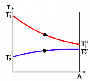
Cochran fire tube boiler

It is a type of boiler in which flue gas flows inside the fire tube, and water is surrounded to these tubes. Convection heat transfer takes place from hot gas inside the tube to the surrounding water to convert it into steam.

Cochran steam boiler

With high efficiency and reduced fuel required, Cochran economizers are cost-effective and used as waste heat recovery to generate steam.

Accessories attached to the Cochran boiler

Attachments on the Cochran Boiler

1. Water level indicator

It indicates water level inside the boiler which help us to maintain water level between high and low level. 

2. Pressure gauge

The steam pressure inside the boiler is measured with the help of an instrument known as a pressure gauge. 

3. Safety valve

 A quick-release valve, mounted on the boiler’s body to protect the boiler from bursting due to excessive pressure is known as safety valve.

When internal pressure reaches the set value of the safety valve, it automatically gets opened, and the high-pressure steam is released.

4. Stop valve

The main function of a stop valve is to stop the operation of the boiler when required and also control flow within the boiler. 

5. Blow off valve

It is used to remove sediment and scale deposits at the bottom of the boiler’s drum while it is in operation and is also used to empty the boiler for cleaning or inspection.

  • Feed check valve mounted on the boiler.

Water flow from feed pimp to boiler is controlled by feed check valve

7. Fusible Plug

It is used to cut-off the fire of boiler in furnace, when the level of water is below the safe zone to avoid damage to the boiler.

Major advantages of the Cochran boiler

Major advantage of Cochran Boiler are listed below

  • Lower cost of initial installation.
  • Floor area requirement is less.
  • Easy to handle and operate.
  • Different types of fuel can be used.
  • It is portable and handy.

Classification of Cochran boiler

Cochran boiler can be classified on the basis of different criteria as Vertical, Multi-tubes, Fire tube, Internally fired, and Natural circulated boiler.

Cochran boiler advantages and disadvantages

Advantages of Cochran boiler 

  • Initial installation cost is less.
  • Required less floor area.
  • Easy to handle and operate.
  • Different types of fuel can be used.

Disadvantages

  • Steam generation rate is low.
  • Carrying out maintenance and inspection work is difficult.
  • Limited pressure range is available.
  • Large area is required for installation because of its vertical design.

Cochran boiler capacity

Boiler capacity is defined as steam production rate at full firing condition and usually expressed on a weight basis. Cochran boiler capacity is in the range of 500 kg/s at 16 bar.

 Cochran boiler design

The main cylindrical body of boiler which in-house water and steam is known as shell of a boiler. The top the boiler have hemispherical dome shaped structure to provide space for steam generated.This shape is provided to to have higher area to volume ratio.It has a compact structure and occupies less floor area. It is mostly used for the low capacity requirement. 

Cochran boiler dimensions

  • Shell diameter: 2.75 m
  • Height of boiler: 5.79 m
  • Heat exchanger tube diameter: 6cm
  • Heating surface 120 m2

Cochran boiler Economizer

An economizer can be used to reduce fuel consumption by up to 6%. It utilizes waste heat from the main engine of the ship to generate steam.

Cochran boiler horizontal

It is mainly used in locomotives and is a multi-tubular, internally fired, fire tube boiler with natural circulation. It is designed to meet sudden fluctuation demands of steam.

Cochran boiler maintenance

Following are the list of some routine maintenance activities carried out on the boiler:

  • Water quality testing and treatment by using chemicals. 
  • Chemical cleaning of soot deposit on economizer by using high-pressure air.
  • Regular blowdown to reduce scale deposits.
  • Maintaining records of testing and inspection log.
  • Overall visual inspection.
  • Lubrication of components.
  • Daily inspection of motor condition.
  • Cleaning of filters and inspection of pilot and burner assemblies.
  • Regular inspection of gasket condition of the steam line and replacement of damaged gaskets.
  • Important to maintaining the required water level inside the boiler’s drum.

Cochran boiler manufacturing process

A numerically controlled plasma cutting machine is used to cut a flat plate. This flat plate is rolled for the required diameter with the help of hydraulic pressure. Longitudinal submerged arc welding is carried out for seamless joining.

Inspection and Quality assurance is carried out throughout the manufacturing process. X-ray technology is used to inspect critical welds. For precise tube-hole alignment, CNC milling is used.

Tubes are manually welded in alignment with tube holes. Furnace, combustion chamber, and front tube shell are fitted to the boiler body.

Pressure testing is done by using a non-destructive method.

Cochran boiler parts

  • Shell
  • Grate
  • Combustion Chamber
  • Fire Tubes
  • Fire Hole
  • Furnace
  • Chimney
  • Fire Brick Lining
  • Manhole
  • Flue Pipe

Cochran boiler principle

Convection heat transfer takes place from flue gases to the water by the fire tubes to form steam.

Cochran waste heat boiler

It is a boiler that produces steam by utilizing waste heat from the exhaust gases of the main propulsion unit of a ship or else use fuel at the port. It is also known as a waste heat recovery boiler.

Cochran water tube boiler

It is a water tube boiler in which water is present in the tube and high-temperature flue gas is present in the surroundings of the tube to produce steam.

Difference between Cochran and Babcock boiler

A Cochran boiler is a vertical fire tube boiler in which flue gas flows through the fire tube. Heat energy is transferred mainly in the form of convection from the hot fire tube to the surrounding water to generate steam.

Babcock boiler is a water tube boiler in which water flows inside the tube, surrounded by hot flue gas. Heat energy is transferred mainly in the form of convection from hot gases to the water inside the tube to generate steam. This type of boiler is used to produce high-pressure steam.

Difference between Cochran boiler and Babcock & Wilcox boiler

A Cochran boiler is a vertical fire tube boiler in which flue gas flows through the fire tube. Heat is transferred from the hot fire tube to the water surrounding the tube to generate steam.

Babcock & Wilcox boiler is a water tube boiler in which water flows inside the tube, surrounded by hot flue gas. The heat is convected from tube to water to increase enthalpy of water and convert it to steam. The high-pressure steam is produced by this boiler. It has a longitudinal drum and horizontal, inclined tube for generating high-pressure steam. The angle of inclination of tubes is about 15° or more with horizontal.

Difference between Cochran boiler and Lancashire boiler

Cochran boiler is a vertical fire tube boiler in which flue gas flow through multiple fire tube. It is used to generate low-pressure steam and has an internally located furnace.

Lancashire is defined as a horizontal fire tube type, internally fired boiler. The length of the Lancashire boiler is approximate 7 – 9 meters, and the diameter is in the range of 2 -3 meters.

The definition of Cochran boiler’s efficiency

The efficiency of the Cochran boiler is defined as the ratio of heat actually required to produce steam in certain time span to heat liberated in furnace during the give time period.

Screenshot 2021 05 21 at 2.20.38 PM

Where,

m1 = is mass of water

hf = specific enthalpy of water at the saturated liquid curve

h1 = specific enthalpy of water in sub-cool region

x = dryness fraction

hfg = difference of enthalpies between saturated vapour and saturated liquid curve at constant pressure.

C = heat capacity of water

History of Cochran boiler

Cochran boiler was initially bought by Thompson-Cochran group as package boiler technology to South Africa and became an international leader in boiler making after joining with Rolls-Royce group.

It was mainly used in ships to produce steam for a different purpose. It can use oil/coal or heat recovery from the exhaust of diesel engine, to produce steam. These boiler’s were also known as composite boilers.

Following are the Limitations of Cochran boiler

  • The steam generation rate is low.
  • Pressure handling capacity is limited.
  • Not suitable for high steam generation rate.
  • Because of its compact size, it is difficult to inspect and maintain.

Problem 1: Feed water supplied per hour 690 kg at 28℃, steam produced 0.97 dry at 8 bar, coal fired per hour 91 kg of calorific value 27,200 kJ/kg, ash and unburnt coal collected from beneath the fire bars 7.5 kg/hour of calorific value 2760 kJ/kg, mass of flue gases per kg of coal burnt 17.3 kg, temperature of flue gases 325℃, room temperature 17℃, and the specific heat of the flue gases 1.026 kJ/kg K.

Find

1. The boiler efficiency

2. The percentage heat carried away by the flue gases

3. The percentage heat loss in ashes

4. The percentage heat loss unaccounted

5. Explain what may have actually happened to the heat included under unaccounted losses.

Solution:

Heat supplied to the boiler per hour= mass of fuel per hour x calorific value of fuel

                                    = 91 x 27,200 kJ/hr

                                    = 24,75,200 kJ/hr

At 8 bar, 

Enthalpy of water at saturated liquid curve (hf) = 721.1 kJ/kg (Data from steam table)

Enthalpy of steam at saturated vapour curve (hg) = 2769.1 kJ/kg

Latent heat of vaporization (hgf) = hg – hf

                                 = 2769.1 – 721.1 kJ/kg

                                 = 2048 kJ/kg

Enthalpy of wet steam = {hf + (X*hfg)}

Where, X = dryness factor

Enthalpy of wet steam = {721.1 + (0.97*2048)}

                                  = 2707.67kJ/kg

Enthalpy of feed water at 28℃ = C x T

Where,

C = heat capacity of water

T = Temperature of water in ℃

Enthalpy of feed water at 28 ℃ = 28 x 4.187

                                  = 117.24 kJ/kg

Heat utilised in steam production per hour

  = mass of steam produced per hour(m) x difference of enthalpy of wet steam and feed water.

  = 690*(2707.67 – 117.24) = 1787396 kJ/kg

1. Boiler efficiency: Ratio of heat utilized in steam formation per hour to heat supplied to the boiler per hour.

= 1787396/2475200

= 0.7221 bar

= 72.21% efficient

2. The percentage heat carried away by the flue gases = mg x Kp (tg – tf)

  Where,

mg = is mass of flue gases = 17.3 kg/kg of coal fired,

Kp = specific heat of flue gases = 1.026 kJ/kg K

tg = temperature of flue gases = 325℃

tf = room temperature = 17℃

Total heat energy carried away by the flue gases

 = 17.3 x 1.026(325 – 17)

 = 5467 kJ/kg of coal.

Percentage heat carried away by the flue gases per kg of coal fired

 = (5467/27200) x 100

 = 20.1%

 3. Percentage heat loss in ashes is the ratio of heating value of ash in kJ/hr to heat supplied to the boiler in kJ/hr.

 = {(7.5 x2760)/2475200} x 100

 = 0.836%

 4. Unaccounted heat loss percentage is calculated by 

 = 100 – (72.21 + 20.1 + 0.836)

 = 6.854%

 5. The heat included under unaccounted losses are those due to radiation, fuel that are not fully burnt, loss of heat with hot ashes etc.

FAQ/SHORT NOTES

Ques.1: Where is Cochran boiler used?

Ans: Cochran boiler is used in following sector:

  • Paper industries
  • Refining industries
  • Chemical industries
  • Different process applications

Ques.2: What are the major three different types of boilers?

Ans:Three different type of boiler is Combi Boiler, Heat(regular) Boiler, System boiler.

  • The Combi Boiler

The boiler having single unit and used to provide hot water for domestic purpose at home.

  • Heat only (regular) boiler

 A hot water cylinder is attached in it.

  • System boiler

A system boiler is mostly similar to Combi boiler other than hot water production. A steel hot water cylinder is attached to it.

Ques.3: What is the area of the heating surface of a Cochran boiler

Ans: With the efficiency of around 70 – 75 percent, the Heating Surface area of Cochran boiler is 120 m2. Working of this boiler is 7 bar and rated for 15 bar.

Que 4: What is Units of break specific steam consumption?

       A. kg/kW-hr          B. kJ/kg-K

       C. kJ/kg              D. kg/kW

Ans: A

Que 5: Maximum thermal energy loss in a boiler is due to 

       A. Flue Gas           B. Ash content

       C. Radiation losses   D. Incomplete combustion

Ans: A

Que 6: Which instrument is used to measured temperature of the flue gases most accurately?

       A. Thermometer      B. Thermocouple

       C. Pyrometer         D. Wheat-stone bridge

Ans: C

Que 7: Cochran boiler is a type of

       A. A horizontal fire tube boiler

       B. A vertical fire tube boiler

       C. A horizontal water tube boiler

       D. A vertical water tube boiler

Ans: D

Que 8: Orientation of water tubes in a simple vertical boiler are

       A. Horizontal

       B. Inclined

       C. Vertical

       D. All of the above

Ans: B

Que 9: The ratio of diameter of internal flue tubes of a Lancashire boiler to diameter of its shell is

       A. One-fourth

       B. One-third

       C. Two-fifth

       D. One-half

Ans: C

Que 10: The process of heating dry steam at constant pressure, above saturation temperature is known as

      A. Isentropic

      B. Super heating

      C. Sub cooling

      D. Isothermal

Ans: B

Specific Enthalpy: 25 Interesting Facts To Know

sp enthalpy of liquid water 300x186 1

Content

Specific Enthalpy definition

Specific enthalpy is the measure of the total energy of a unit mass. It is defined as the sum of specific internal energy and flow work across the boundary of the system.

Units of Specific Enthalpy

The unit of specific enthalpy (h) is kJ/kg.

Specific Enthalpy equation

The equation of specific enthalpy is

h = u + Pv

Where,

h = Specific Enthalpy  

u = Specific Internal Energy

P = Pressure of the system

v = Specific volume of the system

Specific Enthalpy formula

h = u+Pv

h = cp (dT)

Where,

cp= specific heat capacity

dT = Temperature difference

Specific Enthalpy of dry air

It is defined as the product of the specific heat capacity of air at constant pressure and dry bulb temperature

h = cp (T)

Cp: Specific heat of air at constant pressure

Cp(AIR) : 1.005 kJ/kg-K

T: Dry Bulb Temperature

Specific Enthalpy of ethanol

The specific enthalpy of ethanol (C2H5OH) is 2.46 J/g℃

Specific Enthalpy of water at different temperatures

Specific enthalpy of water (hwater) is given by the product of the specific heat capacity of water Cwater and  the temperature. At ambient conditions (Pressure 1 bar), water boils at 100℃, and the specific enthalpy of water is 418 KJ/Kg.

Cwater = 4.18 kJ/kg K

Specific enthalpy of liquid water at atmospheric pressure under condition and different temperature has been illustrated below:

specific enthalpy
Fig 1: specific enthalpy of liquid water vs. Temperature

Enthalpy equation specific heat

Enthalpy is defined as the total energy content of a system. It is expressed as product of mass, specific heat and change in temperature of system.

H = m Cp (Tf – Ti)

Where,

H = enthalpy

Cp =specific heat capacity at constant pressure

m = mass of the system

Ti = Initial temperature

Tf = final temperature

Specific Enthalpy of air

It is defined as the summation of specific enthalpy of dry air and specific enthalpy of moist air.

h = 1.005*t+ω (2500+1.88 t)

h = enthalpy of moist air kJ/kg

t = Dry Bulb Temperature in ℃

ω = specific humidity or humidity ratio in kg/kg of dry air

Specific humidity is defined as the ratio of the mass of water vapour per Kg of dry air in a given volume and given temperature.

Specific enthalpy of air table

Variation of thermodynamic properties of air with respect to temperature at atmospheric pressure condition have been provided below.

Screenshot 2021 05 11 at 6.54.19 AM
Fig 2: Thermodynamic property of liquid gas (image credit :thermopedia)

Specific Enthalpy of liquid water

A Phase diagram of water plotted between temperature and specific entropy illustrate the enthalpy of water at a different state.

Saturated dry steam curve separates super-heated steam from the wet steam region, and saturated liquid curve separates sub-cooled liquid from the wet steam region.

The point where both saturated vapour and saturated liquid curve meets is known as the critical point. At this point water, directly flashed off to vapour.

Note: At critical point, The latent heat of vaporization is equal to zero.

At critical point degree of freedom is zero.

  • Critical point pressure for water is 221.2 bar
  • Critical point temperature of the water is 374℃
  • The line 1-2-3-4-5 represents a constant pressure line.
T S DIA 1
Fig 3: Phase diagram representation on T-S curve

Subcooling: It is the process of decreasing the temperature at constant pressure below the saturated liquid.

Specific enthalpy of liquid water is the difference of enthalpy of water at the saturated liquid line (2) and specific enthalpy of water in sub cool region (1). Unit of specific Enthalpy (h) is kJ/kg.

h1 = h2 – c p(liquid) (T2 – T1)

Where,

h1 = enthalpy of water in sub cool region

h2 or hf = enthalpy of water at saturated liquid curve

Cp (liquid) = 4.18 kJ/kg (specific heat capacity of water)

T2 = Temperature of liquid at saturation point

T1 = Temperature of liquid in sub cool region  

Specific enthalpy of steam

Specific enthalpy of the steam at any arbitrary point (3) in the wet region is given by sum of specific enthalpy at saturation liquid curve at constant pressure and product of dryness fraction and difference of enthalpies at saturation liquid curve and saturation vapour curve as same constant pressure.

h3 = hf + X(hfg)

h3 = specific enthalpy of steam in wet region

hg = specific enthalpy of steam at saturation vapour line

hf = specific enthalpy of steam at saturation liquid line

hfg = hg – hf

Wet Region : It is the mixture of liquid water and water vapour

Dryness Fraction (X): It is defined as the ratio of the mass of water vapour to the total mass of the mixture. The value of dryness fraction is zero for saturated liquid and 1 for saturated vapour.

X = mv/(mv+ml)

Where mv = mass of vapour

        ml = mass of liquid

Specific enthalpy of superheated steam

Super heating: It is a process of increasing the temperature at constant pressure above saturated vapour line.

h5 = h4 + cp(vapour) (T5 – T4)

Where,

h5 = specific enthalpy of steam in super heated state.

h4 = specific enthalpy at saturation vapour curve.

Cp = heat capacity at constant pressure

T4 = Temperature at point 4

T5 = Temperature at point 5

Specific Enthalpy on steam table

Steam table contains thermodynamic data about the properties of water or steam. It is mainly used by the thermal engineers for designing heat exchangers.

Some frequently used values on the steam table has been shown below.

Screenshot 2021 05 10 at 9.29.28 PM
Pressure based saturated steam table (Image credit : www.tlv.com)

Enthalpy and Specific Enthalpy

Enthalpy (H): It represents the total heat content of the system.

The mathematical expression is

H = U + PV

H = Enthalpy of system

U = Internal Energy of system

P = Pressure

V = volume

Change of enthalpy (dH) is defined as the product of mass, specific heat capacity at constant pressure and temperature difference between two state.

dH = mCp(dT)

m = mass of the system

Cp = heat capacity of fluid

dT = change in temperature

SI unit of Enthalpy is kJ

Specific Enthalpy and heat capacity

Specific enthalpy (h) is defined as the summation of specific internal energy and flow work.

The mathematical expression is given by

h = u +Pv

u = specific internal energy

Pv = flow work

SI unit of specific enthalpy kJ/kg

Specific heat capacity (Cp) of water is defined as the amount of heat required to raise the temperature of 1 kg of water by 1 K. For ex specific heat capacity of water is 4184 J/kg-K.

cp = specific heat capacity.

SI unit of specific heat capacity is kJ/kg-K.

Specific enthalpy of combustion

It is defined as the enthalpy change when a substance reacts vigorously with oxygen under standard conditions. It is also known as “heat of combustion”. The enthalpy of combustion of petrol is 47 kJ/g and diesel is 45 kJ/g.

Specific Enthalpy of evaporation

It is defined as the amount of energy that must be added to 1 kg of a liquid substance to transform it completely into gas. The enthalpy of evaporation/vaporization is also known as latent heat of vaporization.

Specific enthalpy of evaporation of steam

The heat energy required by the water at 5 bar pressure to convert it into steam is basically less than the heat needed at atmospheric conditions. With the increase of steam pressure specific enthalpy of evaporation of steam decreases.

Specific Enthalpy of moist air

Specific enthalpy of moist air is given by

h = 1.005*t+ω (2500+1.88 t)

h = enthalpy of moist air kJ/kg

t = Dry Bulb Temperature in ℃

ω = specific humidity or humidity ratio in kg/kg of dry air

Specific Humidity (ω) is defined as the ratio of the mass of water vapour per Kg of dry air in a given volume and given temperature.

Specific enthalpy of saturated steam

The specific enthalpy of a saturated steam at corresponding temperature and pressure is 2256.5 kJ/kg. It is represented by hg.

Specific enthalpy of saturated water

The specific enthalpy of saturated water at standard atmospheric conditions is 419kJ/kg. It is generally represented by hf.

Specific enthalpy of water vapour

At standard atmospheric conditions,i.e 1 bar pressure, water starts boiling at 373.15K. The specific enthalpy (hf)of water vapour at saturated condition is 419 kJ/kg.

Absolute Specific Enthalpy

The enthalpy of the system is measured of total energy in the system. It cannot be measured in absolute value as it depends on change in temperature of the system and can only be measured as the change in enthalpy. For ideal gas, Specific enthalpy is the function of temperature only.

Acrylic Acid Specific Enthalpy

Acrylic acid is used in many industrial products as raw material for Acrylic Easter. It is also used in manufacturing polyacrylates. Specific enthalpy of formation of Acrylic Acid is in the range of -321± 3 kJ/mole.

FAQ/Short Notes

1. Specific Enthalpy of Helium:

Specific heat of helium is 3.193 J/g K. Latent Heat of vapourization of Helium is 0.0845 kJ/mole.

Heat of vaporization of Helium

specific enthalpy
Fig 5: The heat of vapourization of helium (Image credit: people)

2. Can specific enthalpy be negative?

Yes, the enthalpy of formation of ethanol is negative. Enthalpy of formation is defined as the energy removed during the reaction to form compound from elements under standard conditions. The higher negative the enthalpy of formation, the more stable the compounds is formed.

3. Specific enthalpy vs specific heat capacity

Specific enthalpy is the total energy of a unit mass or defined as the sum of specific internal energy and work done across the boundary of the system.

Specific heat capacity is defined as the heat required to raise the temperature of 1 kg of water by 1 K.

4. Specific enthalpy vs specific heat

The heat interaction per unit mass at constant pressure (Isobaric process) is known as specific enthalpy.

5. Air specific enthalpy vs temperature

Specific enthalpy of air is defined as the product of heat capacity of air at constant pressure and change in temperature whereas the temperature is an intensive property of the system by virtue of which heat transfer takes place.

6.Mass enthaply vs specific enthalpy

Mass enthalpy or enthalpy is defined as the total energy content of the system . Its unit is kJ.Specific enthalpy is defined as total energy content of the system per unit mass. Its unit is kJ/kg.

7.Difference between Enthalpy and Entropy

Enthalpy is defined as the total heat content of the system where as the entropy is defined as the total randomness of the system.

8.Why does specific enthalpy of steam on steam tables begin to decrease after about 31 bar?

The liquid and vapour phases of a substance are indistinguishable from each other. If we consider the internal energy of the steam, it should decrease with enthalpy, But as the random vibration of molecules is hindered by other molecules due to increase in pressure.m which results in decrease of specific volume, thereby decreasing internal energy. As the specific enthalpy is defined as the sum of specific internal energy and flow work on boundary of the system, the specific enthalpy also decreases.

For more topics on Mechanical Engineering, please see this link.

Silicon Controlled Rectifier: 19 Facts You Should Know

SCR

What is SCR ?

SCR | Silicon Controlled Rectifier Definition

  • A SCR, sometimes also called Semiconductor Controlled Rectifier is a three-terminal solid state power device and is widely used for various power electronic applications. It is also sometimes called as a thyristor.
  • An Silicon Controlled Rectifier has three terminals namely anode, cathode and gate.
  • The SCR can be turned on by passing a small current through the gate terminal to the cathode, provided the anode terminal is at a higher potential than the cathode.

A typical Silicon Controlled Rectifier looks as follows:

Silicon Controlled Rectifier
Reference : © Raimond Spekking / CC BY-SA 4.0 (via Wikimedia Commons), Laptop Acrobat Model NBD 486C, Type DXh2 – STMicroelectronics TYN408G on Power Supply Unit-4439CC BY-SA 4.0

Silicon control rectifier symbol

An Silicon Controlled Rectifier is denoted by the following symbol for all its uses in circuit diagrams and other representation purposes.

SCR Symbol

Types of Silicon Controlled Rectifier

The thyristors are categorized as follows:

  • The Force-commutated thyristor.
  • Line-commutated thyristor.
  • The Gate-turn-off thyristor (GTO).
  • Reverse-conducting thyristor (RCT),
  • Static induction thyristor (SITH)
  • Gate-assisted turn-off thyristor (GATT)
  • Light activated silicon-controlled rectifier (LASCR).
  • MOS turn-off (MTO) thyristors emitter turn-off (ETO) thyristors,
  • Integrated gate-commutated thyristor (IGCT).
  • MOS-controlled thyristor (MCTs).

Why SCR is called silicon controlled rectifier ?

  • Generally, rectifiers can be classified as controlled rectifiers and uncontrolled rectifiers.
  • Diodes come under the category of uncontrolled rectifiers as they conduct without any control, as long as the anode voltage is greater than cathode voltage (also called forward-bias condition)
  • SCRs, on the other hand, are called controlled rectifiers as they conduct only when the gate terminal is triggered. Thus, by providing a triggering pulse to the gate, we can control the working of the thyristor, as long as it is in the forward bias condition

Thyristor vs SCR

SCRs and Thyristors are essentially the same and can be used interchangeably. In this article also, both the terms will denote the same device.

High Power Silicon Controlled Rectifier

SCRs are known for their high power-handling capability. Natural or line-commutated thyristors having rating of 6000V, 4500A are also available. On an application level, these are huge values and therein lies the importance of SCRs. SCRs can handle such huge amounts of voltages and currents without damaging itself. The characteristics of the SCRs ensures that they will always have important power electronic applications.

Operation of Silicon Controlled Rectifier

  • An SCR can be ON state by forward-biasing the anode-cathode junction and applying a pulse of positive gate current for a short duration. Once the device begins to conduct, we can remove this gate pulse and the Silicon Controlled Rectifier is latched on, though it is not possible to turn off the SCR by any gate pulse.
  • If the anode current attempts to go to -ve, on account of the circuit onto which the SCR is connected, SCR may turn-off and the current will be 0.
  • In its OFF-state, the thyristor will halts a forward polarized voltage and will not be in conducting stage.
  • The I-V characteristics of an SCR can be studied to understand these points in further detail.

It is interesting to note that an SCR can be used for both AC and DC, Once the conditions for turning on are met – forward bias voltage and positive gate pulse – it conducts all currents, regardless of whether it is AC or DC.

Silicon Controlled Rectifier Characteristics

  • Till the thyristor is triggered by a gate pulse, if a positive voltage is applied across the anode-cathode junction, the element is said to be in forward blocking state
  • Once the device starts to conduct, the SCR is ON and can be said to be in forward conducting state
  • If the voltage applied is negative, the device is said to be in reverse blocking region. In reverse blocking state, only a negligibly small leakage current flows in the thyristor.
  • Once the negative voltage increases beyond a value called reverse breakdown voltage, the thyristor will start conducting in the negative direction. This voltage is also called peak reverse voltage. This is also called Zener breakdown or avalanche region.

We may study the following graph of Silicon Controlled Rectifier (SCR) characteristics to get a better idea.

Latching Current

Once the gate pulse is removed, the current flowing from anode to cathode must be more than a minimum vale, called latching current, to keep the device in the ON state. Otherwise, the device goes back it the blocking state.

Holding Current

  • Small anode current is essential to keep the thyristor in the ON-state, That is known as holding current.
  • The holding current is less than the latching current.

Silicon Controlled Rectifier Applications

Due to the controllable nature of the Silicon Controlled Rectifier and their availability in very wide range of voltage and current ratings, SCRs find their use in a wide variety of applications.

Some of them are

  • Variable Speed Motor Drives
  • AC motors, lights, welding machines
  • Fault Current Limiters
  • Circuit Breakers
  • Light Dimmer Circuits
  • Electric Fan Speed Control
  • High Power Electrical Applications

Silicon Controlled Rectifier Dimmer

  • As, SCR is a controllable device, it can be used in dimming circuits.
  • The basic idea behind this process is that the point on the waveform where the device is turned on is changed. Essentially, it is also a form of phase control. It is also called forward phase dimming.
  • Generally, sinusoidal supply is given to the lights. So, as opposed to turning on at the point of zero crossing, we turn on at different instants, thereby controlling the power.
  • Some of the drawbacks of SCR Dimmer circuits are hum/noise, electrical noise(harmonics) and inefficiency.

SCR Heater Control

  • The general idea behind working of SCR Heater is same as that of in SCR Dimmer, i.e we control the power given to resistor loads by changing the instant of turn-on.
  • The SCR heater works by varying the time the electric heater is turned-on & therefore modulating the amount of heat supplied.
  • The SCR control can deliver electrical power in mainly 2 ways, phase angle fired and zero voltage switched modes.

Phase Angle Fired Mode

In this mode, the control is such that a percentage of power is turned on in each cycle (i.e one cycle of an alternating current). This can give smooth & variable power delivery to the heaters. Essentially, the time instant at which a gate pulse is given to the SCR is varied. This is what the term “phase angle” in the title corresponds to.

Zero Voltage Switched

Here, the switches turn and off full cycles of the sinusoidal waveforms proportionately so that   by varying the number of AC cycles, we can get the required power at the output.

SCR Power Controllers

  • The principle behind SCR power controllers are basically what we have discussed before; control the flow of electricity(and hence power) from the supply to the heater.
  • The find uses in industries and manufacturing processes for temperature regulation for different applications.
  • It basically adjusts the firing angle(phase angle from zero-point crossing of sine wave to the instant where gate pulse is applied) to maintain a constant voltage output, which is set.

SCR Motor Controller

  • SCRs can be employed to control the speed of a DC motor using the following electrical circuit.
  • Two SCRs are used to convert the input AC voltage into a pulsating dc voltage.
  • This pulsating dc voltage can be varied by controlling the output of the SCR rectifier circuit, which in turn is controlled by the timing of firing of gate pulses. Essentially, output voltage is varied.
  • In this way, SCR can operate at different levels & apply various voltages to the motor armature, thereby controlling the speed of the DC motor. If the thyristor conductors for shorter durations, its output voltage(of the rectifier circuit) becomes lower, lower voltage is applied to the DC motor and therefore the speed of the DC motor is reduced.

SCR vs TRIAC

  • The main difference between an SCR and a TRIAC is that SCR is a unidirectional device, which means it allows current flow in only one direction, whereas a TRIAC is a bidirectional device i.e it allows current flow in both the directions.
  • For triggering an SCR, a positive gate pulse is required whereas most TRIACs can be triggered by applying either a negative or a positive voltage to the gate terminal.
  • TRIACs are mainly used to control AC power

3 Phase SCR

  • Three-phase SCRs are circuits in which SCRs are used in each phase leg i.e for the 3 phases. The functioning and application of the SCRs are same as before, with only difference being that they are used for 3-phase supplies now.
  • As before, SCRs are used in two control modes, zero-crossing mode and phase angle control mode. Their working is same as that explained before

Frequently Asked Questions

Q. In an SCR silicon controlled rectifier why is the holding current less than the latching current ?

  • Latching current, as defined before, is the minimum current that must be present at the point of gate pulse removal to maintain conduction, whereas Holding Current is the minimum current that is required to be maintained to keep the device in the ON state.
  • The latching current limit is purposely kept greater than holding current so as to avoid misfiring of SCRs and provide smooth operation.

Q. How an SCR is triggered ?

Operation of Silicon Controlled Rectifier

Q. Why SCR is called a controlled rectifier ?

An SCR is called a controlled rectifier because as opposed to a diode, the turn-on time can be controlled for the device. Hence, the voltages at the out of the Silicon Controlled Rectifier are controllable depending on the instant of turn-on.

Q. What is SCR and its types?

Types of Silicon Controlled Rectifier

For more details on SCR, click here

For more articles, click here

Speed Governor Complete Tutorial: 7 Important Facts

Capture 245x300 1

What is a governor in a car?  

Speed governor | Engine governor

Whenever there is a “variation of load on the engine”, there will be change in the engine’s speed. For the maintaining the speed of an engine up to definite limit, a speed governor is utilized. There is a variation in the speed of the engine over a no of rotations because of engine’s load variations. The operation of a speed governor is more or less intermittent and these are critical for all types of engine because its adjustability on the supply of fuel as per requirement. A speed governor is also known as a governor or sped limiter.

Engine governor
Engine governor
Image credit : GlobbetAshton Frost engine governorCC BY-SA 3.0

Governor symbol

Symbol of Speed governor

What are the two main components of a governor system?

Types of Governor

The Governor categorized in two types.

  • Centrifugal Governor
  • Inertia Governor

Centrifugal Governor

Centrifugal governor consists of a pair of governor balls attached to the arms, which are supported by the spindles as shown in the figure. This whole system is mounted on the shaft; this shaft is linked to the engine of the shaft thru a bevel gear mechanism. Under this assembly, a free to slide sleeve is attached to the shaft. A bell crank lever is connected to the sleeve. This lever connects the throttle valve and sleeve.

The activity of the governor be subject to the speed variation. The variations in the bell crank lever give the motion to the sleeve and eventually to the spindle and ball. The governor’s action is produced by the centrifugal effect of the masses of the balls.

When the speed of the engine increase, the balls intend to rotate with higher radius from the centered shaft position, this caused the sleeve to slide in the upward way on the spindle and these variations of the spindle will result in the closing action of the throttle-valve up to the mandatory limit thru the bell-crank lever mechanism. When the speed declines, the balls will rotate at a lesser radius, so the throttle valve opens accordingly.

It is a more common type of governor.

Type of Centrifugal Governors

The centrifugal governor is further classified as follows:

Capture

Inertia Governor

Inertia governor is based on the ‘Principle of Inertia of Matter’.

For Inertia Governor, more force acts with the centrifugal forces on the balls, whose position are decided by the angular acceleration and de-acceleration of the spindle in addition to the centrifugal force acts on the ball.

In the inertia type of governor, appropriate linkages and spring used for opening and closing the throttle valve according to the changes in the position of the ball.

In an inertia governor, when the acceleration or deceleration of an engine is very low, the additional inertia force practically becomes zero. In that case, the inertia governor becomes a centrifugal governor.

The inertia governor’s response is faster than that of the centrifugal governor.

Engine Governor

The throttle valve of an engine is operated by the governor called engine governor using a mechanism explained earlier.

Sensitiveness of a Governor

The movement of the sleeve essential for the minimal change in the speed of an engine is the measure of sensitiveness of a governor.

A governor’s sensitiveness is described as the ratio of the change in-between the highest and least speed to the mean equilibrium speed.

Thus,

Sensitiveness=frac{range of speed}{mean speed} =frac{N2-N1}{N} =frac{2(N2-N1)}{N}

Where,

N=mean speed

N1=minimum speed corresponding to full load conditions

N2=maximum speed corresponding to no-load conditions

Turbine Governor

A turbine governor is a component of a turbine control system that controls rotational speeds according to loading conditions.

A turbine governor provides on-line and start-up control for the generator, which drives the turbine.

Steam Turbine Governing

In a steam turbine, there is an inconsistent flow of steam. A steam turbine governing is a procedure of maintaining a constant rotation speed by controlling the steam turbine’s flow rate to the steam turbine.

Elevator Governor | Over-speed Governor

When the speed of an elevator crosses predetermined speed limits, a mechanism acts to control the system known as over speed governor.

A speed governor located in the elevator is a component of the safety system of the governor.

The position of the speed governor in the elevator is determined by the However, in many cases, it is installed in the machine room of the elevator.

Air Vane Governor

An air vane governor is a pneumatic type of governor.

In this system, airflow is used to regulate the throttle opening. This air vane of the governor is made up of plastic or metal. This governor also consists of the flywheel.

Speed Limiter for Car

A speed governor is used as a speed limiter for cars’ engines. It regulates the fuel supply of the car with varying load.

There are three types of the governor which are being used in automobiles:

·       Mechanical Governor

·       Hydraulic Governor

·       Pneumatic Governor


Woodward Governor

Wood ward governor is a well-known manufacturing company of governors.

Governor Switch | Governor Gear

Governor Switch, Governor Gear are parts of an evolved form of a speed governor.

Question and Answers related to Governor

What are the two main components of a governor system? 

The two main components of a governor are mechanical arrangement and hydraulic unit.

How does a mechanical governor work?

Centrifugal governor consists of a pair of governor balls attached to the arms, which are supported by the spindles as shown in the figure. This whole assembly is mounted on the shaft; this shaft is connected to the engine of the shaft using bevel gear. Under this assembly, a free to slide sleeve is attached to the shaft via a bell-cranks. This lever connects the throttle valve and sleeve.

As we already know, governor’s action is dependent on the speed variations. The changes in the bell crank lever give the motion to the sleeve and ultimately to the spindle and balls. The governor’s action is produced by the centrifugal effect of the masses of the balls.

During the engine’s speed increment, the ball will intend to rotate at a higher- radii from shaft’s position and caused the sleeve to sliding in the upward direction and this movement of the spindle consequences in the closing of the throttle-valves and if speed declines, these balls will rotate with less radii, so the throttle valve controlled accordingly.

What are the three types of governors?

There are three types of the governor which are being used in automobiles:

  • Mechanical Governor
  • Hydraulic Governor
  • Pneumatic Governor

What is Governor Sensitivity?     

Governor sensitivity is known as the sensitiveness of a governor.

The movement of the sleeve for the minimal change in the speed of an engine is the measure of sensitiveness of a governor.

Sensitiveness=frac{range of speed}{mean speed} =frac{N2-N1}{N} =frac{2(N2-N1)}{N}

Where,

N=mean speed

N1=minimum speed corresponding to full load conditions

N2=maximum speed corresponding to no-load condition

Which governor is more sensitive?     

Proell governor is known as the most sensitive governor in the centrifugal type of governors.

Whereas Porter governor is more sensitive than Watt governor.

What are the applications of a governor?

  1. A speed governor is used as a speed limiter for cars’ engines. It regulates the fuel supply of the car with varying load.
  2. A governor is used in elevators. When the speed of an elevator crosses predetermined speed limits, a mechanism acts to control the system known as over speed governor.
  3. A speed governor is used in different types of turbines. A turbine governor provides on-line and start-up control for the generator, which drives the turbine.

Which governor is used in cars? | What is a governor in a car?

A speed governor is used as a speed limiter for the engines of cars. It regulates the fuel supply of the car with varying load.

There are three types of the governor which are being used in automobiles:

  1. Mechanical Governor
  2. Hydraulic Governor
  3. Pneumatic Governor

What is the range of governor?

The variance between the maximum and minimum speed of a governor is known as a governor’s range.

What is the meaning of speed governor?

Whenever there is a variation in the load on the engine, there is a variation in the speed of an engine and to maintain the engine’s speed at stated limit, a speed governor is employed.

Can you remove a speed governor?

Yes. A speed governor is inbuilt for a car from the company, but it can be removed if we want.

Is speed governor compulsory?

Yes. It has been made compulsory in many countries to have a speed governor.

How does a speed governor work?

The throttle valve of an engine is operated by the governor, when the load on the engine shaft increases, it’s speed will decline except the fuel supply is increased by the throttle valve opening. Similarly, if the load on the engine shaft declines, its speed will increase unless the fuel supply is reduced by closing the throttle-valve appropriately to slowdown engine’s to actual speed.

What is a Hartnell governor?

A Hartnell governor is a centrifugal type of governor in which it is loaded with a spring.  Additional spring is used to apply an extra force to the spring.

Where is Hartnell governor used?      

A Hartnell governor is used in regulating the speed of the engine.

Which lever is used in Hartnell governor?  

The lever used in Hartnell governor is a bell crank lever.

What are the types of speed governor?

Governors are broadly classified into two types.

  1. Centrifugal Governor.
  2. Inertia Governor.

For more mechanical related articles click here

    Mastering the Fundamentals of Strike and Dip in Structural Geology

    strike and dip

    Strike and dip are essential measurements used in structural geology to describe the orientation of planar features, such as bedding planes, fault surfaces, and foliation, in three-dimensional space. The strike is the horizontal angle between the planar feature and a north-south line, typically measured in degrees clockwise from north, while the dip is the vertical angle between the planar feature and a horizontal plane, also measured in degrees.

    Understanding the Basics of Strike and Dip

    The orientation of a planar feature in three-dimensional space can be fully described by two angles: the strike and the dip. The strike is the direction of the horizontal trace of the planar feature, while the dip is the angle between the planar feature and a horizontal plane.

    Measuring Strike and Dip

    Geologists typically use a compass and an inclinometer to measure the strike and dip of a planar feature in the field. The process involves the following steps:

    1. Place the compass on the planar feature and measure the azimuth of the strike, which is the horizontal angle between the planar feature and a north-south line, measured clockwise from north.
    2. Use the inclinometer to measure the dip angle, which is the vertical angle between the planar feature and a horizontal plane.
    3. Determine the dip direction, which is the direction in which the planar feature is dipping, by adding 90 degrees to the strike direction.

    Alternatively, strike and dip can be measured from geologic maps or remote sensing data using software tools, such as the one described in this publication, which can automatically digitize and calculate the strike and dip of geologic layers from satellite images.

    The Three-Point Problem

    The three-point problem is a common method used to calculate the strike and dip of a planar feature from the intercept data of three or more drill holes. This method involves determining the position of three or more points on the planar feature in three-dimensional space, and then using trigonometry or stereonet projections to calculate the strike and dip.

    The steps involved in solving the three-point problem are as follows:

    1. Identify the coordinates of three or more points on the planar feature, typically obtained from drill hole intercept data.
    2. Use the coordinates of the three points to construct a plane in three-dimensional space.
    3. Calculate the strike and dip of the planar feature using the following formulas:

    4. Strike = tan^-1 [(y2 – y1) / (x2 – x1)]

    5. Dip = tan^-1 [√((x2 – x1)^2 + (y2 – y1)^2) / (z2 – z1)]

    where (x1, y1, z1), (x2, y2, z2), and (x3, y3, z3) are the coordinates of the three points on the planar feature.

    The three-point problem can be solved using graphical methods, such as structure contours or stereonets, or by using computer programs, such as the freeware available at this website.

    Extracting Quantitative Structural Information

    strike and dip

    In addition to the strike and dip measurements, geologists often use other quantitative information to understand the structural geometry of geologic features. The GMDE program, described in this publication, is a versatile tool that enables geologists to extract a wide range of quantitative structural information from geologic maps and satellite images, including:

    • Digitizing of strikes and dips
    • Calculation of stratigraphic map thickness
    • Determination of piercing points on faults
    • Construction of down-plunge projections and vertical cross sections

    By combining strike and dip measurements with other quantitative data, geologists can gain a more comprehensive understanding of the structural geology of a region, which is essential for a wide range of applications, such as mineral exploration, hydrocarbon exploration, and geohazard assessment.

    Advanced Techniques and Applications

    Beyond the basic principles of strike and dip, there are several advanced techniques and applications that geologists can utilize to further their understanding of structural geology:

    Stereonet Projections

    Stereonet projections, also known as equal-area or Schmidt net projections, are a powerful tool for visualizing and analyzing the orientation of planar and linear features in three-dimensional space. Geologists can use stereonets to plot strike and dip measurements, identify structural patterns, and perform kinematic and dynamic analyses of deformation.

    Structural Contours

    Structural contours are lines drawn on a map that connect points of equal elevation on a planar feature, such as a bedding plane or a fault surface. By constructing structural contours, geologists can visualize the three-dimensional geometry of a planar feature and infer information about its deformation history.

    Numerical Modeling

    Advances in computational power and numerical modeling techniques have enabled geologists to develop sophisticated models of structural deformation, incorporating factors such as rock rheology, stress fields, and tectonic boundary conditions. These models can be used to predict the evolution of structural features and to test hypotheses about the tectonic history of a region.

    Remote Sensing and GIS

    The use of remote sensing data, such as satellite imagery and LiDAR, combined with geographic information systems (GIS) software, has revolutionized the way geologists collect and analyze structural data. These tools allow for the rapid and accurate digitization of strike and dip measurements, as well as the integration of structural data with other geologic and geophysical datasets.

    Structural Geology in Exploration and Resource Development

    Strike and dip measurements, along with other structural data, are essential for a wide range of applications in the exploration and development of natural resources, such as minerals, hydrocarbons, and geothermal energy. Structural geology plays a crucial role in identifying and characterizing potential exploration targets, as well as in the design and optimization of extraction and production activities.

    Conclusion

    Strike and dip are fundamental measurements in structural geology that provide crucial information about the orientation of planar features in three-dimensional space. By understanding the principles of strike and dip, as well as the various techniques and applications for their measurement and analysis, geologists can gain valuable insights into the structural geology of a region and its implications for a wide range of scientific and practical applications.

    References

    1. Measurement of Strike and Dip of Geologic Layers from Remote Sensing Data – New Software Tool for ArcGIS: https://www.researchgate.net/publication/234191038_Measurement_of_Strike_and_Dip_of_Geologic_Layers_from_Remote_Sensing_Data_-_New_Software_Tool_for_ArcGIS
    2. Three-Point Problem: Calculating Strike and Dip from Multiple DD Holes: https://rogermarjoribanks.info/three-point-problem-calculating-strike-dip-multiple-dd-holes/
    3. GMDE: Extracting Quantitative Information from Geologic Maps and Satellite Imagery: https://pubs.geoscienceworld.org/gsa/geosphere/article/16/6/1495/591697/GMDE-Extracting-quantitative-information-from
    4. Microimages Technical Guide: Measuring Strike and Dip: https://www.microimages.com/documentation/TechGuides/71StrikeDip.pdf
    5. YouTube Video: How to Measure Strike and Dip: https://www.youtube.com/watch?v=ab_o-qbQEPQ