Hydronic heating system: 19 Facts You Should Know

air Page 1 1 300x192 1

Content

Key notes

what is a hydronic heating system?

The hydronic system is used to warm your home. The water is used as a working fluid in most of the system. First, it will get heated by a boiler or other heating sources. Then, the water will be circulated through the combustion chamber via a heat exchanger.

Hydronic radiant floor heating system

The heated water is passed through the tubes inside the radiator on the floor. The floor is constructed such that it contains some holes like porous material. It may be wood or tiles with porous holes in them. The radiated heat is circulated inside the home. The use of carpet is avoided on the floor due to its low conductivity of heat.

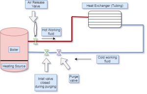
hydronic heating system diagram Schematic
air Page 1 1
Schematic diagram of complete system

How to bleed air from hydronic heating system ?

  • First of all, finds and identifies the air bleed valve near to radiator. This valve is small and cylindrical with one inch in height. The head of this valve is a slotted screw with a small nozzle inside it.
  • After finding the air bleed valve, turn the air bleed valve in an anti-clockwise direction to open it. If air is present in the heating system, the air will come out with the valve opening through the nozzle. The water particles also come out with air. Keep valve open for some time till the complete water starts coming out without air. Close the valve once you notice the steady water flow.
  • Closing of the valve can be done by rotating the air valve in a clockwise direction. In some heating systems, there are multiple valves installed in the system. In present case, we have to repeat this steps for all air valve

hydronic baseboard heating system

In Hydronic baseboard heating system, the heater will heat the liquid inside the system. The liquid should possess the non-toxicity. It may be water or some special type of oil. It should also give radiant heat to warm our house inside.

This type of system is similar to working of radiator, but the difference is that it possesses less space area to compare to the radiator.

hydronic radiant floor heating system | hydronic floor heating system | hydronic radiant heating systems

The radiant floor heating system is used to heat the area by using infrared radiations. It provides warm comfort to people inside the room. Compared with another heating air method, a radiant floor heating system is more efficient and convenient. In addition, the heat flows from ground to up so that the temperature is more maintained with a little cold.

In this kind of system, the heat will get radiated from the floor. This may be more beneficial for getting more convenient heat. We can feel more similar like one feels heat from stove burner at some distance from the stove. In this system, the air is not directly heated; the heat is radiated from ground level. It makes more warming effect and comfort to one using this system.

In a radiant floor heating system, the working fluid used is water. This water will get heated from outside heating sources like a water heater, geothermal or boiler, etc. The water is circulated through the PEX tubes, which are installed inside the home. It might be considered as a dry install or wet install

what is a hydronic heating system ? | hydronic water heating system | aqua hot hydronic heating system | how does a hydronic heating system work | basic hydronic heating system

The hydronic system is used to warm your home. The water is used as a working fluid in most of the system. First, it will get heated by a boiler or other heating sources. Then, the water will be circulated through the combustion chamber via a heat exchanger. Once the water absorbs the heat from the boiler, it will pass through the baseboard or radiator to rejects its heat. Finally, the baseboard or radiator is installed inside your home. This is a cyclic process of water to get heat from the heating source and reject heat inside a house from the baseboard.

Safety is provided in the system to avoid getting damage. For example, if the water level decreases in the baseboard, it will automatically shut off the boiler’s working to prevent an accident.

There is some indirect heating system work on two in one principle. The heat is utilized for warming homes as well as stored in a tank for other purposes.

hydronic heating system diagram Schematic | residential hydronic heating system diagram schematic | hydronic heating system schematic | boiler hydronic heating system diagram

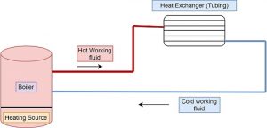
The schematic diagram of present system is shown in figure below,
hydronic heating system
Schematic diagram of Basic Hydronic heating system

types of hydronic heating systems in detail | hot water hydronic heating systems boilers | electric hydronic baseboard heating systems | boiler hydronic heating system

There are widely known three hydronic systems as expressed as below,

Hydronic radiant floor heating system :

In this heating system, the floor is covered with a huge radiator. The heated water is passed through the tubes inside the radiator on the floor. The floor is constructed such that it contains some holes like porous material. It may be wood or tiles with porous holes in them. The radiated heat is circulated inside the home. The use of carpet is avoided on the floor due to its low conductivity of heat.

Baseboard :

This system is also known as a “hot water baseboard heating system.” This system is a attractive due to its efficient working.

The hot water tubes with fins are kept inside the steel housing of the baseboard. The fins are useful to radiate heat from the pipe. The hot water is circulated through tubes.

Hydro air heating system :

Hydro air heating system includes duct and air handler unit. The hot working fluid is passed through the heat exchanger built in the air handler unit. The air will get heated with an air handler heat exchanger and distributed to the home. This system is less costly as compared to the radiant floor heating system. In addition, this system includes a duct, which can also be useful in an air conditioning system.

hydronic heating system components | hydronic heating system parts | expansion tank hydronic heating system | hydronic heating system expansion tank | components of hydronic heating system

The components used in hydronic systems are explained below. The main outside element of this system is the heating source. It may be a boiler, geothermal, water heater, etc.

Expansion tank:

The expansion tank is utilized to keep the excess working fluid passing through the system. The volume of working fluid is raised when it will get warm. To accommodate this volume, the expansion tank is used in this heating system. There is mainly two types of expansion tank are used in this system: either compression tank or standard basic tank.

Centrifugal pump :

This is also the main component of the system. It is used to circulate water throughout the system from the heating source to the home (heat exchanger). The centrifugal pump continuously runs to obtain the cyclic process of the system. The impeller is mounted on a shaft that pressurize the water to get circulate through the system. To avoid corrosion in the pump, the impellers are made of anticorrosive materials like bronze.

Air separator:

It is required to separate the air which is trapped in water. The air separator is the device that prevents air from getting trapped. The water will get pass through an air separator. The air separator is constricted with a wire screen which separates the air bubbles from the water. The trapped bubbles will get removed from the air vent. The separation of air in this system is necessary to avoid corrosion of metal and compressibility effect.

Air vent :

It is used to take out the air from the system. This device is installed with an air separator. It is preferred to use an automatic air vent device because the opening and closing of the device are very convenient. It is available in automatic as well manual mode.

hydronic forced-air heating system

Hydro air heating system :

Hydro air heating system includes duct and air handler unit. The heated working fluid is passed through the heat exchanger unit kept in the air handler. The air will get heated with an air handler heat exchanger and distributed to the home. This system is less costly as compared to the radiant floor heating system. This system includes a duct which can also be useful in an air conditioning system.

open-loop hydronic heating system | tankless hydronic heating system | open hydronic heating system

In an open-loop hydronic system, the working water in the system will get mixed with hot drinking water. The system is the unique for both working fluid

hydronic heating system operating pressure | closed loop hydronic heating system pressure

The operating pressure in a hydronic heating system is around 12 to 15 PSI (Pound per square inches). The pressure is enough to fill the water through the entire piping circuit. There are variations in operating pressure according to the various hydronic heating system and their components. This pressure range also depends on the range of centrifugal pumps used for water circulation through the system.

closed hydronic heating system

In a closed-loop heating system, the loop of the PEX tube is used as a heat exchanger with compactness. The connection of this tubing is with heat pumps and indoor units. The antifreeze solution is added to the working fluid to prevent it from freezing. This working fluid circulated through the complete system in a cyclic process. This system is reliable and economical if it is perfectly installed.

How to bleed air from hydronic heating system | purge air from the hydronic heating system with circulators | hydronic heating system air vent | hydronic heating system air eliminator

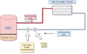
The water contains dissolved air with water molecules. In a hydronic system, the temperature of working fluid is raised at certain temperature. The heating of water separates the air from water. Therefore, it is required to take out this air from the system to avoid some losses. If these airs get trapped with hot water inside the tubes, it will damage the tube, generate noise and block the flow of hot water. In addition, the working efficiency of the total system will get decreased because of trapped air.
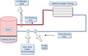
hydronic heating system purging
Schematic of Hydronic heating system purging

Generally, the air bleed valve is provided to take out this trapped air in the hydronic system. This air bleed valve is installed near to radiator.

The air bleeding from the heating system will follows the steps as given below,

  • First of all, finds and identifies the air bleed valve near to radiator. This valve is small and cylindrical with one inch in height. The head of this valve is a slotted screw with a small nozzle inside it.
  • After finding the air bleed valve, turn the air bleed valve in an anti-clockwise direction to open it. If air is present in the heating system, the air will come out with the valve opening through the nozzle. The water particles also come out with air. Keep valve open for some time till the complete water starts coming out without air. Close the valve once you notice the steady water flow.
  • Closing of the valve can be done by rotating the air valve in a clockwise direction. In some heating systems, there are multiple valves installed in the system. In present case, we have to repeat this steps for all air valve

how does air get into a hydronic heating system

The air will get trapped in a hydronic heating system with many causes, let’s see some of the main causes as below,

  • The air will get trapped when we are filling water into the system
  • If we backflush the water from the hydronic heating system
  • The water contains dissolved air with water molecules. In a hydronic heating system, the temperature of working fluid will get raised at a certain temperature. The heating of water separates the air from water.
  • It will get trapped if any leakage in the heating system

how to flush a hydronic heating system | hydronic heating system flush | flushing hydronic heating systems | how to drain hydronic heating system

The method of flushing or draining for the hydronic heating system is explained with steps as below,

  • Switch off the heating device first, let working fluid get cool and safe
  • Close the valve for the water supply
  • Join the one end of the hose to the drainage valve of the boiler.
  • Open the drain valve of the boiler, also open all air vent valve of the heat exchanger (radiator)
  • Now, after completion of the drain, close all air vent valves and drain valves.
  • Start filling system again to make system work again.

how to install hydronic in-floor heating systems | building a hydronic heating system | hydronic radiant floor heating systems design | how to install hydronic heating system | hydronic radiant heating system design

The installation of the hydronic in-floor heating system can be done with following probable steps,

Step 1: The system is designed properly to estimate required parts and tools for installation

Step 2: make a bed of concrete and provide insulation over it. This insulation prohibits heat get flow in the bottom of tubes.

Step 3: Make a proper arrangement of reinforcement wire and put a tube over it properly.

Step 4: Install all tubes properly as per heat exchanger standard

Step 5: make floor slab ready completely

Step 6: Before start working on the system, properly check for any leakages in the system

Step 7: Fill the slab from the top and cover it

Step 8: Now, the system is ready to start work. Make proper adjustments of valves and devices so that in between, you can operate it if needed.

Step 9: Start your system and enjoy a warm atmosphere inside your home.

Step 10: The system is working first time, so that check for any troubleshoot and solve the problem if any arising

Step 11: Enjoy Your Cozy House!

hydronic heating system problems | hydronic heating system maintenance

There are some problem occurs during the working of a hydronic heating system working and operation. It is pointed as below,

  • Hydronic Heating  basic faults
  • Flushing: periodic flushing is necessary for any hydronic heating system. The power flushing is required to be done every ten years. All the system suppliers recommend it.
  • Air trapping: Air trapping in the radiator is one of the main issues in any hydronic system which stops its works. The air is taken out from the system through air vent valves periodically.
  • The cost of sludge and scale removal is too high for any hydronic system. In addition, the sludge and scale formation depends on the quality of water used as a working fluid.
  • Failure of the circulation pump and its performance
  • Boiler noise creates a noisy atmosphere and inconvenient
  • Antifreeze agent adjustment
  • The periodic cleaning is required for complete system

hydronic heating system temperature

the  temperature order for two different hydronic systems is given as below; this data is probable

  • The temperature range in the radiant floor heating system is around 30 to 60 degrees centigrade.
  • The typical temperature range for the baseboard system is approximately 55 to 70 degrees celsius.
  • According to data, at this temperature range, the life of the boiler is expected 45 years

how to fill hydronic heating system with antifreeze

The following are the steps to be followed to fill the antifreeze agent in the hydronic heating system,

The first step is to close the feed valve, which is located near the boiler

In most hydronic heating systems, the location for forcing the antifreeze is the boiler drain valve. Identify this valve properly

Start pushing the antifreeze in the boiler by using boiler drainage

You should add the required antifreeze so that the system’s pressure reaches around 12 to 15 PSI (Pound per square inches).

hydronic heating control systems | controls in hydronic heating system

Hydronic heating system control should be capable of controlling the efficiency and the comfort inside the home.

We should have proper control of the system, either it managing single room or multi rooms.

hydronic heating system glycol | antifreeze hydronic heating system

In a cold climate, the antifreeze agent is needed so that the water will not get freeze inside the tube and blockage. Generally, glycol is used as antifreeze in the hydronic heating system. The glycol posses a lower freezing temperature, so that system working fluid stays in the liquid phase in extremely cold conditions.

purge air hydronic heating system | how to get air out of hydronic heating system | how to remove air from hydronic heating system

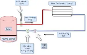
The Purging of air from the system can be done with the following steps,
air Page 1
Purging of air
  • First of all, finds and identifies the air bleed valve near to radiator. This valve is small and cylindrical with one inch in height. The head of this valve is a slotted screw with a small nozzle inside it.
  • After finding the air bleed valve, turn the air bleed valve in an anti-clockwise direction to open it. If air is present in the heating system, the air will come out with the valve opening through the nozzle. The water particles also come out with air. Keep valve open for some time till the complete water starts coming out without air. Close the valve once you notice the steady water flow.
  • Closing of the valve can be done by rotating the air valve in a clockwise direction.  In some heating systems, there are multiple valves installed in the system.

For related topics, please click here
Superheat Refrigeration: 15 Facts You Should Know

Capture 1

Content

Superheat refrigeration | Superheat definition in refrigeration | superheat refrigeration definition

We can define superheat as a temperature measurement of vapour when it is above its boiling point of saturation.

Superheat is an essential concept for any refrigeration or air conditioning system. The people associated with refrigeration and AC system must have to understand this concept and its effect.

The super heat in the refrigeration system can be measured on the evaporator and compressor. Though, it is depending on the design where you measure reading. There are two primary places to notice reading that is evaporator and compressor.

In a refrigeration system, evaporator superheat considered for detailed study when one goes through the superheating concept.

How to adjust superheat in refrigeration system? | How to set superheat on a refrigeration system

In refrigeration and air conditioning system, the superheat generally controlled with a thermal expansion valve. The setting stem of the valve is turned to fix the static superheat.

The thermal expansion valve is turned clockwise to raise static super heat. The turning clockwise also decrease the refrigerant flow passes from the thermal expansion valve.

In reverse, If we turn the thermal expansion valve in a counter-clockwise direction.

The effect is opposite to above; the static super heat is raised, and refrigerant flow through the thermal expansion valve is raised.

It is concluded that the thermal expansion valve is a widely used device to control the super heat.

What is superheat in the refrigeration system?

Super heat and subcooling are critical to the refrigeration cycle but can be challenging concepts to visualize.

In refrigeration and air conditioning system, the super heat and subcooling are very important to adjust and understand, but it isn’t easy to visualize both concepts.

Let’s understand superheat firstly,

As we know, boiling is the temperature at which the liquid phase turns into the vapour phase. If we heat that vapour above the boiling point, we can call that vapour a super heated vapour.

For example, we consider the below conditions,

Suppose in the evaporator; the refrigerant is getting boiled at a temperature around 40 degree centigrade (Pressure condition -low). Suppose that refrigerant is continuously heated above 40 degree centigrade and increasing temperature of vapour refrigerant. This condition of refrigerant is considered as super heating refrigerant. This super heat can be calculated with general formula. It can be estimated with readings of current temperature and boiling temperature, as shown below.

The super heat condition is somehow tricky in the case of air conditioning. The system should be such that the refrigerant is wholly boiled before it leaves the evaporator. If a few droplets of liquid remain in the system, it can cause hard damages to the compressor component in the air conditioning system.

Similarly, care should be taken, the processes evaporation and superheat happens in evaporator and compressor.

The processes like condensation and subcooling happen in the component condenser.

Measuring superheat refrigeration

The superheated steam can be measured with the following steps,

  • 1. First step is to identify the suction line. If we consider simple logic, then the suction line holds a larger diameter. The other two refrigerant lines are with a smaller diameter. Fix suction side refrigerant gauge to service port near to condenser coil.
  • 2. Fix the clamp on the temperature sensor on the suction line near to service port.
  • 3. Notice the reading of temperature and pressure on the suction line. The measurement can be done with a pressure gauge and temperature sensor.

Suppose 45F is saturation temperature measured in the evaporator coil. The measurement of temperature with the temperature probe is 55F.

Super heat =Measured temperature on suction line – Saturation temperature

                   = 10F

The superheat of this example is 10F.

Degree of superheat in refrigeration

The degree of super heat is a vital definition to be understood. It is helpful in refrigeration air conditioning about refrigerant.

It can be defined as the Amount with which super heating temperature overtakes the saturation temperature of the vapour. (Pressure remains same in this condition)

Compressor superheat refrigeration | Total superheat in refrigeration system

In a refrigeration system, the total super heat is complete super heat in the low side of the system. It is starting from the evaporator with 100 % saturation vapour and ending on the compressor inlet.

Total super heat = Evaporator super heat + Suction pipeline super heat

The refrigerator technician can measure it by taking readings of temperature and pressure on the inlet of the compressor. It is also termed compressor super heat.  The measurement device can be a thermocouple or temperature sensor. The pressure gauge also notices reading at the compressor inlet.

R22 refrigerant superheat table | refrigerant superheat chart | Refrigerant superheat diagram

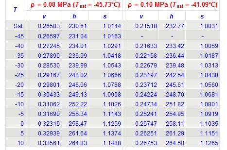
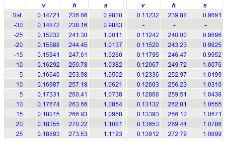
The following are the charts that can be useful to find the information of R22 refrigerant properties at various temperatures.

superheat
superheat R22
Superheat R22
R22 Refrigerant superheat Chart Credit Engg. Toolbox

Refrigeration cycle superheat and subcooling

The value of super heating and subcooling is helpful to get know-how much refrigerant remaining in the evaporator and condenser, respectively. If it is higher, it indicates not required level, but it gives complete information of refrigerant if it is lower.

The subcooling system uses the thermal expansion valve, which operates in the range of 10F to 18F.

The higher value of subcooling shows that more refrigerant is coming back into the refrigerant.

Superheat refrigeration cycle

As we know that at the evaporator inlet, the state of refrigerant is liquid. The refrigerant state is turned from a liquid to vapour at the outlet of the evaporator coil. The evaporation of the liquid is done before the evaporator coil the low temperature so that vapour remains cold even if evaporated. This cold vapour passes through the evaporator coil, where it will absorb heat and get superheated vapour—this phenomenon of getting sensible heat from the evaporator increase the tonnage of refrigeration. The efficiency of the system will be higher due to superheating.

Adding or removing refrigerant to change superheat | Do you add refrigerant to raise superheat?

Adding and removing refrigerant to the refrigeration system affects the super heat.  The suction, super heat will be decreased if we add refrigerant. If we remove refrigerant from the system, the super heat on the suction side will increase.

If your measuring instruments are not working properly, You do not try to add or remove refrigerant. It may cause damages. The system will get overcharged.

Causes of high superheat in refrigeration

There are many causes of super heat in refrigeration and air conditioning system. Some of the primary reasons are given as below,

The measuring devices are not working correctly or the wrong indication. It is possible that the device is not correctly adjusted or partially broken.

It is possible that charging of refrigerant not appropriately done. The system is undercharged, so the super heat indication is higher.

It may be possible due to blockage of the line; the refrigerant will get restricted inside the line.

The filter or drier will get blocked because of high super heat. The system will get moisture content.

The evaporator heat load can be increased and reach maximum.

It can be said that high super heat is indicating less refrigerant inside the evaporator coil.

Because of fewer refrigerants inside the evaporator coil, it will get higher heat load condition. The pressure condition is lower than primary.

How to read superheat conditions in a refrigerant table?

Follow the steps given below to charge refrigerant with super heat method of charging,

  • Measure the atmospheric temperature outside the home
  • Measure the indoor wet-bulb temperature of the air
  • Take your instruction manual; Search the super heat chart inside the manual. Using values of the first two steps, find the super heat and other information that may be helpful for calculation.

Refrigeration superheat method | Superheat refrigeration charging

If the metering device is fixed orifice type, the super heat method is used for charging refrigerant. The metering device is chosen based on the condenser requirements. It is mentioned in the input-output manual.

Follow the steps given below to charge refrigerant with super heat method of charging,

  • Measure the atmospheric temperature outside the home
  • Measure the indoor wet-bulb temperature of the air
  • Take your instruction manual; search the super heat chart inside the manual. Using values of the first two steps, find the super heat and other information that may be helpful for calculation.
  • Take the temperature sensor and put it on the suction line for measurement
  • Measure the suction pressure by using gauge installed on the suction line
  • As we know that the super heat can be given as,  Super heat =Measured temperature on suction line – Saturation temperature

Add refrigerant to decrease the super heat or remove refrigerant to increase the super heat

The most popular method of charging in super heat refrigeration is the weigh-in method. If we know the perfect length of lines in the refrigeration system, the weigh-in method will be perfect.

Refrigeration superheat setting

In refrigeration and air conditioning system, the superheat generally controlled with a thermal expansion valve. The setting stem of the valve is turned to fix the static superheat.

The thermal expansion valve is turned clockwise to raise static super heat. The turning clockwise also decrease the refrigerant flow passes from the thermal expansion valve.

In reverse, If we turn thermal expansion valve in a counter-clockwise direction.

The effect is opposite to above; the static super heat is raised, and refrigerant flow through the thermal expansion valve is raised.

It is concluded that the thermal expansion valve is a widely used device to control the superheat.

What is subcooling in refrigeration?

The subcooling is somehow reverse of super heat. It is also known as undercooling.  We can say that subcooling is a liquid phase with a temperature less than its boiling point.

As we know, water will change its phase from liquid to vapour at a temperature of 100 degree centigrade. The condition of the water at room temperature around 20 degree centigrade is called subcooled water.

Subcooling and super heating are very important to identify and control refrigeration and air conditioning systems for efficient working.

For more articles to related topics, please click here

Benson Boiler: 13 Facts You Should Know

Content

FAQ/SHORT Note

  • What are the major disadvantages of Benson boilers
  • Benson boiler is drumless
  • Maintenance of Benson boiler

Benson boiler

Mark Benson invented Benson boiler, in year 1922.

It can be known by following,

  • High-pressure boiler,
  • Supercritical,
  • Water-tube category,
  • Forced circulation boiler (Water and steam)

It is a supercritical boiler as the feed water is pressurized at supercritical pressure. The reason behind compressing water is to eliminate bubble formation inside the water tube. The appearance of the bubble can not be possible due to the same density of compressed water and steam. Here in the Benson boiler, the water is compressed at supercritical pressure. Because of this process, the latent heat  is going to be zero. There is no latent heat of vaporization, so the water is directly converted into steam. The intermediate stage of bubble formation is eliminated in this boiler.

Working of Benson boiler | Benson boiler experiment

In the this boiler, the water is compressed by feed water pump at supercritical pressure ( order of 225 bar ). There is no latent heat of vaporization, so the water is directly converted into steam. The intermediate stage of bubble formation is eliminated in this boiler. This prevention of bubble formation is the main benefit of the this boiler compared to other average boilers.

We can quickly notice from the figure given in this article,

The feedwater pump is used to compress water and circulate it through the system. The feedwater pump is used to raises the pressure nearly 225 bar. The water is passed through an economizer to absorb waste heat and feed water heating.

After getting primarily heated by the economizer, the water is getting passed through the radiant heater. In a radiant heater, The water is getting heat by radiation, and the temperature of the water increase such that it partly changes its phase into steam. Its temperature is nearly supercritical.

This two phase mixer of steam and water is passed through a convective evaporator in the next step. Here in the convective evaporator, the two phase mixer turned into steam. We can consider it as superheated steam to some degree.

In this boiler, steam from the convective superheater is passed through the superheater to raise its pressure at the required level. This superheated steam is capable of turning a turbine and valuable for electricity generation.

The turbine is rotated with this superheated steam. The turbine is coupled with an electricity generator. Ultimately, the rotation of the electricity generator produces electricity.

Benson boiler design

The different design approach is applied to the this boiler to control proper operating conditions and different high pressure conditions. The boiler should be capable of allowing perfectly stated dry out. The control of the boiler steam generator is such that which includes considering the initial start to an endpoint. It should consist of the water entering into the economizer to superheater outlet.

The two phase flow is maintained at a critical point, and with load around 55%, the flow is turned single phase from two phases.

The control and design of Benson boiler should possess the following criteria,

  • Starting of boiler in cold condition
  • A restart of boiler in warm condition
  • Sustain Cycling load
  • Shut down.

The design is carried out based on Benson point. The Benson point is the point at which the vertical steam separator should operate dry. The fluid inserted in the boiler should be converted into steam due to this vertical steam separator.

The boiler circulation pump kept off during the Benson point. The water is pressurized with the feedwater pump to meet the required operation of the furnace with the required enthalpy raise. With this method, The function of the evaporator and superheater is controlled according to load. The load on the system will get stabilized.

The steam will get reheated if it violates the requirement. The setpoint load is maintained with control of temperature at various stages.

The temperature in these conditions is maintained by the use of spray at temperature.

Advantages, disadvantages of Benson boiler

There are many benefits of high pressure boilers. Out of them, some benefits are stated below for study,

  • The weight of the Benson boiler is expected less compared to other boilers because there is no drum in the this boiler. The drum is the central part of weight increment. It can reduce about 20% weight of the boiler.
  • As we know that the supercritical pressure is provided to water. The bubble formation is eliminated in this boiler. The water is directly converted into steam because of it.
  • This boiler is considered a lightweight boiler.
  • The maintenance of this boiler can be possible in a smaller floor area. The erection requires less area.
  • The diameter of water tubes in the this boiler is smaller. The benefit of small diameter tubes reduces the chances of explosion.
  • This type of boiler is rapid as it can start in few minutes, around 15 minutes.
  • This boiler is easily transportable compared to other boilers.
  • It is noticed that the thermal efficiency of this boiler is expected about 90%. For any boiler, thermal efficiency states its performance

There are few disadvantages of the boiler.

  • If the flow of water is not proper, the water tube will get overheated. This will affect the working of the boiler.
  • Suppose the water is not pure and contains some impurities. The formation of deposits can be found on the surface of tubes.
  • The operation can face difficulties if the load is variable.

Application of Benson boiler

For any boiler, the initial use is to generate useful steam. The generated steam is utilized for different purposes. Steam is widely used to generate electricity. The steam is being used for process heating in some applications like paper mill, milk pressurization etc. The operating conditions of Benson boiler are as below,

The pressure of steam: 250 bar,

The temperature of steam: 650 degree centigrade,

Output steam rate: 135 – 150 tonnes per hour

Benson boiler drum

It is without a drum.

The weight of the this boiler is expected less compared to other boilers because there is no drum in the this boiler. The drum is the central part of weight increment. It can reduce about 20% weight of the boiler.

Benson boiler features

Because no drum is used in this boiler, the mobility of this boiler parts is not difficult.

Benson boiler function

The function of the boiler is similar to the working of the boiler. The initial use of the boiler is to generate useful steam. How is this steam generated? Here are the answers to this question,

There is no latent heat of vaporization, so the water is directly converted into steam. The intermediate stage of bubble formation is eliminated in this boiler. This prevention of bubble formation is the main benefit of this boiler compared to other average boilers.

We can quickly notice from the figure given in this article,

In the first step,

The feedwater pump  compresses water and circulate it through the system. The feedwater pump raises the pressure at 225 bars. The water is passed through an economizer to absorb waste heat and feed water heating.

Second step

After getting primarily heated by the economizer, the water is getting passed through the radiant heater. In a radiant heater, The water is getting heat by radiation, and the temperature of the water increase such that it partly changes its phase into steam. Its temperature is nearly supercritical.

Third step

This two phase mixer of steam and water is passed through a convective evaporator in the next step. Here in the convective evaporator, the two phase mixer turned into steam. We can consider it as superheated steam to some degree.

Fourth step

In the this boiler, steam from the convective superheater is passed through the superheater to raise its pressure at the required level. This superheated steam is capable of turning a turbine and valuable for electricity generation.

Final step

The turbine is rotated with this superheated steam. The turbine is coupled with an electricity generator. Ultimately, the rotation of the electricity generator produces electricity.

Benson boiler pressure

The operating conditions of Benson boiler are as below,

  • The pressure of steam : 250 bar,
  • The temperature of steam : 650 degree centigrade,
  • Output steam rate : 135 – 150 tonnes per hour

Benson boiler schematic diagram | Benson boiler diagram

The schematic diagram of the Benson boiler is shown below with every part.

Benson high pressure boiler

Yes, It is a higher pressure boiler. It is also considered a supercritical boiler.

Benson point boiler

The design is carried out based on Benson point. The Benson point is the point at which the vertical steam separator should operate dry. The fluid inserted in the boiler should be converted into steam due to this vertical steam separator.

The boiler circulation pump kept off during the Benson point. The water is pressurized with the feedwater pump to meet the required operation of the furnace with the required enthalpy raise. With this method, The function of the evaporator and superheater is controlled according to load. The load on the system will get stabilized.

Define Benson boiler

Mark Benson invented Benson boiler, in year 1922.

It can be known by following,

  • High pressure boiler,
  • Supercritical,
  • Water-tube category,
  • Forced circulation boiler (Water and steam)

This is a supercritical boiler as the feed water is pressurized at supercritical pressure. The reason behind compressing water is to eliminate bubble formation inside the water tube. The appearance of the bubble cannot be possible due to the same density of compressed water and steam.

Efficiency of Benson boiler

It can be said that the thermal efficiency of the Benson boiler is expected about 90%. For any boiler, thermal efficiency states its performance.

FAQ/SHORT Note

What are the major disadvantages of Benson boilers?

There are few disadvantages to the boiler.

If the flow of water is not proper, the water tube will get overheated. This will affect the working of the boiler.

Suppose the water is not pure and contains some impurities. The formation of deposits can be found on the surface of tubes.

The operation can face difficulties if the load is variable.

Benson boiler is drumless

Yes, the Benson boiler is without a drum.

The weight of the this boiler is expected less compared to other boilers because there is no drum in the this boiler. The drum is the central part of weight increment. It can reduce about 20% weight of the boiler.

Maintenance of Benson boiler

The maintenance of the this boiler is already discussed in the design of the Benson boiler topic. Kindly refer to it.

Quasi-Static Process: 15 Important Explanations

gif 6

Content

FAQ/Short Notes

  • What is a quasi static force ?
  • Is reversible process quasi static ?
  • Is adiabatic process quasi static ?
  • What are the examples of Quasistatic processes in our daily lives ?
  • Why a reversible process is necessarily a Quasi static process ?
  • Since the pressure is uniform in the quasi static process, how can there be any work done?

Quasi-static process definition

It can be defined in simple words process happening very slowly, and all state passed by this process is in equilibrium.

The meaning of the word “Quasi” is almost. The static means the thermal properties are constant concerning time. All the reversible processes are quasi. The slow rate of the process is the main characteristic of the this process.

Non quasi-static process

It is not realized for any finite difference of the system. Most of the processes happening around us (in nature) can be termed as non quasi-static process.

Both of the process can be well understood by diagram as shown below,

Quasi-static process
Diagram Quasi static and non Quasi static process

It helps analyze. It is primarily studied in books and references. We already know the introductory study of thermodynamic starts with quasi processes. We can readily notice work PdV in this diagram. The curve of non quasi looks half-circle type. The quasi-static method is represented by a straight line.

Difference between quasi-static and reversible process

We can define a reversible process as if the system restores its initial or starting stage and there is no effect of the process on the surrounding.

In a reversible process, the process follows the same path in the forward and reverse functions. There is no impact of the system on the surrounding. Ideally, this type of process can not be possible due to friction.

It can be defined in simple words process happening very slowly, and all state passed by this process is in equilibrium.

There is no friction present in this process. So, we can say that ideally, the processes are reversible.

There is no entropy generation in both processes. We can make any process reversible if we continue the process at a prolonged rate.

Example of quasi-static process

We can consider the static compression process as an example of the quasi-static process. In this process, the system’s volume will change very slowly, but the pressure of the system remains throughout the process.

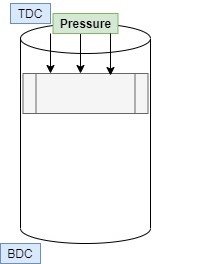
Compression process with cylinder and piston is shown in figure below,

piston cylinder 1
Compression process of quasi-static process

Characteristics of quasi-static process

It is a thermodynamic process where the process occurs at a very slow rate. We can say the process occurs at near to rest condition.

Every point or stage in the this process is considered in equilibrium conditions.

We can say that control on the quasi process is effortless. In the non quasi-static process, the control can be challenging compared to ideal quasi. The reason behind it is the speed of the process.

It is a thermodynamic process in which the time taken for the complete process will be infinite.

It is highly efficient as there is no loss in this process. There is no friction or heat generation due to friction. In the case of a non quasi process, friction is present, which is ultimately loss so less efficient than quasi.

This process is reversible in nature.

Device working on quasi-static process produce maximum work

Common quasistatic processes

Ideally, the quasi reversible process can not possible practically. There is always some loss in any system. With some assumptions, we can consider some processes as quasi processes.

  • Ideal Gas processes at a slow rate.
  • Compression process at a prolonged rate
  • Reversible Processes.
  • Growth of tree

Huge Temperature Reservoir

Condition for an ideal gas in a quasi-static adiabatic process

If we consider the quasi adiabatic process, there is some condition to be satisfied. If ideal gas is compressed from state 1 to state 2, then

P1 and V1 Is the initial condition of the system,

P2 and V2 Is the final condition of the system,

The condition for the system is,

PV^{gamma }= Constant

We can write this condition for both condition as below,

P1V1^{gamma }= P2V2^{gamma }

Conditions for quasi-static process

It is a thermodynamic process where the process occurs at a very slow rate. We can say the process occurs at near to rest condition.

Every point or stage in this process is considered in equilibrium conditions.

We can say that control on this process is very easy. In the non quasi-static process, the control can be challenging compared to quasi. The reason behind it is the speed of the process.

It is a thermodynamic process in which the time taken for the complete process will be infinite.

This process is highly efficient as there is no loss. There is no friction or heat generation due to friction. In the case of a non quasi process, friction is present, which is ultimately loss so less efficient than quasi.

This process is reversible in nature.

Device working on this process produce maximum work

Difference between quasi-static and non quasi-static process

It can be defined in simple words that it is the process happening very slowly, and all state passed by this process is in equilibrium.

This process is always reversible in nature.

There is no friction or loss present.

It is not realized for any finite difference of the system. Most of the processes around us (in nature) can be termed a non quasi-static process.

The non quasi process is always irreversible.

There is always friction and loss present in the system.

We can write relation for entropy generation,

dS = frac{dQ}{T} + I

Where dS denotes entropy change in system

The entropy change in the system can be positive, negative, or zero.

Heat transferred in an infinitesimal quasi-static process

Heat transfer equation for this ideal process can be written in following foam for calculation,

dQ = left ( frac{Cv}{nR} right )cdot left ( Vcdot dP right )+left ( frac{Cp}{nR} right )cdot left ( Pcdot dv right )

Here

dQ = Heat transfer

Cv= Constant volume heat capacity

n= no. of moles of substance

R= ideal gas constant

Cp= Constant pressure heat capacity

V = volume,

dV = Differential volume

P= Pressure,

dP = Differential pressure

Importance of quasi-static process

It is proposed in 1909 as a ” quasi-static process.” It is an essential process in the field of thermodynamic for analysis. It is providing maximum output work in the system. Though this process is ideal, this process in the various study is vast.

In this process, the system remains in equilibrium for infinitesimal time. The reasons behind its importance in the field of engineering are

1. This process is easy for analysis

2. Any device working on this process produces maximum work. There is no loss of any energy.

Non quasi-static process example

Every process in nature is a non quasi-static process,

Those processes do not occur at a prolonged rate. You can consider any processes non quasi-static process.

  • Fast Heat transfer,
  • Fast compression,
  • Expansion,

Non-quasi-static cyclic process

It is not realized for any finite difference of the system. Most of the processes around us (in nature) can be termed a non quasi-static process.

We can readily notice the curve in the diagram given below. As we know, the non quasi-static process does not return with the same path. The backward process is always with a different direction to be considered a cyclic process.

Quasi-static process diagram

The diagram for both of the process shown below for the expansion process.

Quasi 1
Quasi-static and Non Quasi-static Diagram

Quasi-static process entropy

We can write relation for entropy generation,

dS = frac{dQ}{T} + I

Where dS denotes entropy change in system

The entropy change in the system can be positive, negative, or zero.

Quasi-static process equation

It can be derived for various processes in thermodynamics. The equation for different process with the constant property is given below,

Process with Constant pressure (Isobaric process)

W_{12}= int PdV

Process with Constant volume (Isochoric process)

W_{12}= int PdV = 0

Process with Constant temperature (Isothermal processe)

W_{12}= P1 V1cdot lnfrac{V1}{V2}

Polytropic process

W_{12}= frac{P1V1 - P2V2}{n-1}

FAQs

What is quasi static force ?

It can be stated as the force applied very slowly on the system. Due to this force, the system deforms very slowly with infinite time. This type of force can be defined as a quasi-static force.

Is reversible process quasi static?

This process is always reversible.

There is no friction or loss present.

It is not realized process for any finite difference of the system. Most of the processes around us (in nature) can be termed a non quasi-static process.

Is adiabatic process quasi static ?

An adiabatic process is a process with no heat transfer. It is also considered as an isentropic process means constant entropy of the system.

There are some conditions of the process to be quasi.

If the adiabatic process occurring at a very slow rate, then it can be considered as quasistatic adiabatic process

What are the examples of Quasi static processes in our daily lives?

It is an ideal process in nature; still, the process that occurs very slowly can be considered as quasi.

Growth of tree,

Why a reversible process is necessarily a Quasi static process?

This process is always reversible in nature.

There is no friction or loss present. There is no heat loss at all in this process

It is not realized for any finite difference of the system. Most of the processes around us (in nature) can be termed a non quasi-static process.

Since the pressure is uniform in the quasi static process, how can there be any work done ?

If the pressure is constant in any system with the this process, the work done can be given by the following equation,

Process with Constant pressure (Isobaric process)

W_{12}= int PdV

Fourier’s law | It’s All Important with 6 FAQs

heat transfer conduction 300x246 1

Content

Fourier’s law of heat conduction        

Fourier’s law of conduction heat transfer can be states as below,

“The heat transfer rate passes from the material or specimen is directly proportional to the cross-sectional area (perpendicular area) from which heat is passing through, and temperature difference along the end surfaces of the material.”

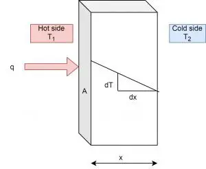
Fourier's law
Fourier’s law of heat conduction

We can write this statement mathematically as,

q \\oe A \\frac{dT}{dx}

q = - K A \\frac{dT}{dx}

Where,

q = heat transfer rate in watt (W or J/s)

K = Thermal conductivity of material or specimen (W / m K)

A = Cross-sectional area from which the heat is passing through in m2

dT = Temperature  difference between the hot side and cold side in K ( Kelvin )

dx = Thickness of material in m (thickness between hot side to cold side)

Most important: Here in the equation, the negative sign indicates that the heat always flows in the direction of decreasing temperature.

Fourier’s law equation   

The equation of heat conduction law is as derived above. It is widely used to solve problems on heat conduction and analysis. The fundamental of the equation remains the same, but the parameters will be changed upon shape and situation of object.

q = - K A \\frac{dT}{dx}

Fourier’s law spherical coordinates  

The heat conduction law applied to cylinder and equation is given as below,

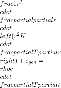
\\frac{1}{r^{2}}\\cdot \\frac{\\partial }{\\partial r}\\cdot \\left ( r^{2}K\\cdot \\frac{\\partial T}{\\partial r} \\right )+e_{gen}= \\rho c\\cdot \\frac{\\partial T}{\\partial t}

Here, at any location the area

A= 4\\Pi r^{2}

,

r is radius of considered cylindrical portion,

Cordinates
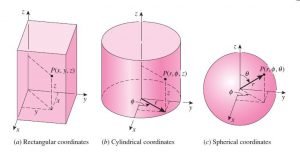
Rectangular, cylindrical and spherical coordinates Image Credit Book Cengel and Ghajar

Fourier’s law cylindrical coordinates

The heat conuction law applied to cylinder and equation is given as below,

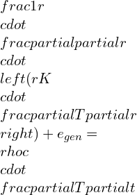
\\frac{1}{r}\\cdot \\frac{\\partial }{\\partial r}\\cdot \\left ( rK\\cdot \\frac{\\partial T}{\\partial r} \\right )+e_{gen}= \\rho c\\cdot \\frac{\\partial T}{\\partial t}

at any location the area A = 2πrL,

r is radius of considered cylindrical portion,

Fourier’s law experiment

Conduction heat transfer is occurred by microscopic diffusion and collisions of molecules or quasi-particles inside an object because of a temperature difference. If we see microscopically, then diffusing and colliding any material includes molecules, electrons, atoms.

Typically, metals have free electrons mobility inside an object. This is the reason behind its good conductivity.

Consider two-block A and B,

Block A is very hot

Block B is cold

block
Experiment for Fourier’s law of heat conduction

Suppose we join these two blocks and insulate all other outer surfaces. The insulation is provided to reduce surrounding heat loss from the block. You can quickly get the idea that the heat energy will flow from hot block to cold block. The heat transfer will continue until both of the blocks attain the same temperature (temperature equilibrium).

It is one of the method of heat transfer in both blocks. It is conduction heat transfer mode. Using the equation of heat conduction law, we can calculate the heat transfer with this experiment. It is very informative and important practical to be performed in heat transfer lab ( Mechanical engineering and Chemical engineering)

Fourier’s law history

Fourier started his work to express conduction heat transfer in 1822. He has also given the concept of Fourier series and Fourier integral. He was a mathematician. His law on conduction is well known on behalf of his name, “Fourier’s law of heat conduction.”

Fourier’s law units

Fourier’s law of heat conduction is stated for heat transfer. So, we can consider the unit of heat transfer for it. The unit of heat transfer is the watt ( J/s) W.            

Fourier’s law assumptions

There are some assumptions made for Fourier’s law of heat conduction. The law only applicable if following conditions will be followed and satisfied.

Fourier’s law of heat conduction example

There are many examples of law of heat conduction in day-to-day life. Some examples are discussed below.

There is hot coffee inside the mug. Now you know that heat will be transferred from the hot side to the cold side. Here, the heat transfer occurs from the inner wall to the outer wall of the mug. It is conduction heat transfer and based on Fourier’s law of heat conduction.

We can consider the wall of our house as for example.

If there is internal heat generation in the rod, heat will flow in the interior portion to outer surfaces.

You can touch any electrical and electronics equipment. You will get realize some heat. These all devices can be the example of Fourier’s law.                            

Fourier’s number

It is a dimensionless number derived by a non-dimensionalization heat conduction equation.

 Fourier’s number is denoted by Fo

F_{o} = \\frac{kt}{L^{2}}

Where,

L is plate length (Diameter in case of the cylinder) in m

K is the coefficient of gradient transport

T is time in s       

Fourier’s law flux

According to heat conduction law law,

The heat flux can be defined as the heat flow per unit area in unit time is directly proportional to the temperature difference between the hot and cold side (Temperature gradient.)

Heat flux

The heat flux can be defined as the heat flow per unit area in unit time is directly proportional to the temperature difference between the hot and cold side (Temperature gradient.)

Heat flux equation

The equation for heat flux is given as below,

q^{-} = - K\\frac{\\\\Delta T}{\\Delta X}

Where,

q- is heat flux in w / m2

K is thermal conductivity in w / m K

ΔT /ΔX is a temperature gradient,

Heat flux units

The unit of heat flux is   w / m2

FAQs   

What is Fourier’s law

                “The rate of heat transfer through the material or specimen is directly proportional to the cross-sectional area from which heat is passing through, and temperature difference along the end surfaces of the material.”

We can write this statement mathematically as,

q \\oe A \\frac{dT}{dx}

q = - K A \\frac{dT}{dx}

Where,

q = heat transfer rate in watt (W or J/s)

K = Thermal conductivity of material or specimen (W / m K)

A = Cross-sectional area from which the heat is passing through in m2

dT = Temperature  difference between the hot side and cold side in K ( Kelvin )

dx = Thickness of material in m (thickness between hot side to cold side)

Most important: Here in the equation, the negative sign indicates that the heat always flows in the direction of decreasing temperature.   

What are the assumptions of Fourier s law of heat conduction?

There are some assumptions made for Fourier’s law of heat conduction. The law only applicable if following conditions will be followed and satisfied. Fourier’s law of heat conduction can be compared with newton’s law of cooling and fick’s law of diffusion. The assumptions are different in every law.

  1. Conduction heat transfer will take place under steady-state conditions of an object.
  2. The flow of heat should be unidirectional.
  1. The temperature gradient will not be changed, and the temperature profile should be linear.
  2. The internal heat generation should be zero.
  3. The bounding surfaces should be adequately insulated.
  4. The material should be homogeneous and isotropic.

What is proof of the Fourier s law of heat conduction and the negative gradient?

The proof of Fourier’s law of heat conduction is already given in topic “Fourier’s law.”

The negative gradient is used because the heat always flows in decreasing temperatures. 

This question is very important for interview because interviewer always try to check your fundamental knowledge.          

How does Fourier’s law of heat conduction contradict the theory of relativity?

Fourier’s law contradicts the theory of relativity due to its instantaneous heat propagation through heat diffusion. If we consider time-dependent heat diffusion with a partial differential equation, The growth of heat flux will be with relaxation time. This time is in order of 10-11. Heat propagation takes infinite time in nature. The relaxation time is negligible.

If we eliminate relaxation time, then the equation becomes Fourier’s law of heat conduction. It is violating the popular theory of Einstein (theory of relativity). The velocity of light in a vacuum is 2.998 * 108

How is the physics behind Fourier’s law different from the one behind Newtons Law of cooling           

As we are already knowing, Fourier’s law is used for conduction heat transfer, and Newton’s law of cooling is used for convection heat transfer. Suppose you have a question that why two different laws are required for the heat transfer rate analysis. The reason behind it is modes of heat transfer are different from individual physics.

Conduction heat transfer is occurred by microscopic diffusion and collisions of molecules or quasi-particles inside an object because of a temperature difference. If we see microscopically, then diffusing and colliding any material includes molecules, electrons, atoms. They transfer kinetic and potential energy microscopically to each other. This energy is known as internal energy in the object. The law states conduction heat transfer is Fourier’s law.

Convection heat transfer in any object can be defined as heat transfer from one molecule to another by moving fluids or flow of fluid. Newton’s law of cooling defines convection heat transfer.

The physics used for the individual process is different. Hence, the governing law for an individual is different. 

What are the similarity between Newtons law of viscosity, Fourier’s law of heat conduction, and Fick’s law of diffusion?

It is the analogy between these equations.

Fourier’s law of Heat Conduction

It states the conduction heat transfer process. The equation can be written as below,

The equation for heat flux is given as below,

q^{-} = - K\\frac{\\\\Delta T}{\\Delta X}

Where,

q- is heat flux in w / m2

K is thermal conductivity in w / m K

ΔT /ΔX is a temperature gradient,

Fick’s law of Diffusion 

It is used to describe and state the mass transfer process. The equation for mass transfer can be written as below,

m^{-} = -D \\left ( \\frac{dC}{dX} \\right )

(dC/dx) is gradient of concentration

D is transport property diffusivity

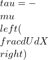
Newton’s law of Viscosity 

It is used for momentum transfer and widely used to study viscosity of any fluid.

\\tau = -\\mu \\left ( \\frac{dU}{dX} \\right )

Here, (du/dx) is the velocity gradient

μ is the viscosity of fluid

Thus, you can analyze three different laws straight away about these equation’s relativity.

To read more articles to related topic please click here

Thermal Diffusivity: 23 Interesting Facts To Know

Image5

Content

Thermal diffusivity definition

Thermal diffusivity is defined as the ratio of conducted heat to heat stored in material per unit volume.

Unit of Thermal diffusivity

The unit of thermal diffusivity is given as m2/s

Thermal diffusivity formula

The equation of thermal diffusivity is given by,

α = k/ρ

Where,

α is thermal diffusivity,

k is thermal conductivity  (w/mK)

? is the density of the material (kg / m3)

Cp is the specific heat (J/ kg k)

Thermal diffusivity of water

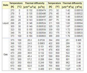
The thermal diffusivity of water changes with temperature and pressure. If we consider atmospheric pressure condition, then the thermal conductivity values with temperature are given as below table.

Thermal diffusivity
Thermal diffusivity of water and gas Credit Engineering toolbox

Thermal diffusivity of air

The thermal diffusivity of air with temperature change is shown in the above table. Generally , the thermal diffusivity of gas is more than liquid in practice. we will study is more in next topic.

Thermal diffusion

Thermal diffusion of substance is the relative motion of the molecules due to temperature gradient.

Thermal diffusivity of aluminium

Thermal diffusivity of aluminium material is given as 9.7 * 10-5 m2/s

Flash method Thermal diffusivity

The flash method is used to determine the thermal diffusivity of the material. The short duration radiant energy pulse is passed through the sample. The laser or light flash lamp source is used for radiant energy. The piece will absorb the emitted energy. The process is repeated for the sample. Due to this emitted radiation, there is a temperature increase of the material sample. The infrared temperature detector records this increase in temperature.

The duration of the measured signal is calculated. The thermal diffusivity will be found from the following equation.

α = 0.1388/l2(t2)

=

Where L is the sample thickness,

t/2 is the half time,

we can find thermal diffusivity, specific heat, and density using the flash method.

The schematic diagram of the flash method is shown in the figure below

Laser Flash Method scheme
Flash method of thermal diffusivity Credit Linseis

How to measure Thermal diffusivity

The thermal diffusivity can be measured using the flash method as discussed above. in this method, the short energy pulse is radiated one end, and temperature rise is calculated on the other end.

Thermal conductivity and thermal diffusivity

To differentiate between thermal conductivity and thermal diffusivity, consider two materials having the same thermal conductivity but with different thermal diffusivity. Both will permit the same rate of heat flow in the steady-state condition. At the start of the heat transfer process, the material with higher thermal diffusivity will reach a steady-state first compared to other material since it retains less heat energy. Heat energy penetrates fast through this material, but after getting a steady-state, the rate of heat flow will be the same. Also, remember that the material having less thermal diffusivity takes more time to reach the steady state.

Thermal diffusivity measurement techniques

There are mainly three types of thermal diffusivity measurement techniques.

  • Flash method
  • Thermal wave interferometry
  • Thermographic method

Thermal diffusivity of asphalt

The thermal diffusivity of the asphalt (Ah-70) is 0.123 mm2/s,

Asphalt (Ah-90) 0.128 mm2/s

Thermal diffusivity of rubber

The thermal diffusivity of the rubber material is in the range of 0.089-0.13 mm2/s

Thermal diffusivity values

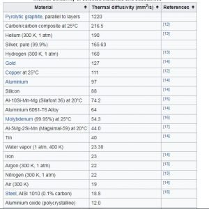
Thermal diffusivity values for various materials are given in the table below. The values are changes with properties like temperature. These values are given for standard temperature and pressure.

Capture
Thermal Diffusivity of various material Credit Wikipedia

Thermal diffusivity symbol

The symbol of thermal diffusivity is α

The highest Thermal diffusivity is of

The highest thermal diffusivity is of pure silver 165.63 mm2 / s

Thermal diffusivity of sand

Thermal diffusivity of dry sand varied from 0.6 * 10-7 to 7.0 * 10-7 m2/s.

Thermal diffusivity heat transfer

There are three modes of heat transfer conduction, convection and radiation. Heat conduction is dependent on main two properties. One is thermal conductivity and thermal diffusivity. Thermal conductivity is well-known property, but thermal diffusivity is not well known. It defines the rate of heat transfer through a given medium.

The rate of heat transfer is faster is the thermal diffusivity is higher. Thermal diffusivity is balancing between the medium of heat transfer and heat storage.

The Thermal diffusivities for gases are generally

The thermal diffusivities of gases substance are found more than liquid substance

Thermal diffusion coefficient

It is one of physical parameter which describes the dependency of mass diffusion flow of the mixture. In other words, the thermal diffusion coefficient is the ratio of a temperature gradient to the absolute temperature.

Thermal diffusion meaning

Thermal diffusion of substance is the relative motion of the molecules due to temperature gradient.

Glass Thermal diffusivity

The thermal diffusivity of glass is 0.34 * 10-6 m2/s  at normal atmospheric condition.

Stainless steel Thermal diffusivity

The thermal diffusivity of stainless steel at 100 °C is 4.55 *10-6 m2/s

Thermal diffusion ratio

The thermal diffusion ratio is the ratio of the thermal diffusion coefficient to the concentration coefficient.

FAQs

Thermal diffusivity of gas vs liquid

The thermal diffusivities of gases substance are found more than liquid substance

Which material has the highest Thermal diffusivity

The most increased thermal diffusivity is of pure silver 165.63 mm2 / s

Application of Thermal diffusivity

The conduction heat transfer in any apparatus requires the study of thermal diffusivity. The industries are using the analysis of thermal diffusivity to optimize the heat transfer rate.

If we take a particular example, then insulation is one example. In insulation, the thermal diffusivity of the material is minimum so that it can resist maximum heat flow.

We are using computers, laptops and other electronic gadgets. Do you know what the method to extract heat from devices is? Yes, it’s Heat sinks.

Heat sink requires higher thermal diffusivity to transfer faster heat from any gadgets.

An increase in heat transfer in any electronics degrades its performance. The higher thermal diffusivity material should be used to improve its performance in that case.

Thermal diffusivity of concrete

The thermal diffusivity of the concrete is 0.75 *10 -6 m2/s

What is the physical significance of thermal diffusivity?

Thermal diffusivity can be defined as the ratio of the thermal conductivity of the substance to the heat storage capacity of the substance.

The ratio defines the generated heat gets diffused out at a specific rate. The higher value of thermal diffusivity indicates that the time required for heat diffusion is less. The study of the equation of thermal diffusivity can be possible by the higher value of thermal conductivity or the lower value of heat capacity.

Image5

Thermal diffusivity is helpful for more intransient heat transfers. In steady-state heat transfer, the thermal conductivity is enough to study.

Why is the thermal diffusivity of gas greater than liquid even though the thermal conductivity of the liquid is greater than gases?

Thermal diffusivity means the ability of a material to transfer heat and store the heat at an unsteady state. A faster heat transfer can be possible if the thermal diffusivity is higher. The lower thermal diffusivity of material means the storage of heat in it.

Gas possesses low volumetric heat capacity because of low density. Due to low volumetric heat capacity, the value of thermal diffusivity is high.

Liquid possesses a high heat capacity compare to gas; hence thermal diffusivity is lower in the liquid.

What is the order of thermal diffusivity for solid, liquid, and gas?

The order of thermal diffusivity in solid, liquid and gas as shown below,

Gas > Liquid > Solid

What is the difference between momentum diffusion and thermal diffusion?

Momentum diffusion

It can be considered the kinematic viscosity of the fluid, i.e. the ability of the fluid to flow the momentum. Momentum diffusion is occurred by shear stress in a fluid. Shear stress causes a random and any direction movement of molecules.

Thermal diffusion

It can be defined as thermal conductivity divided by the multiplication of density and specific heat capacity (when the pressure is constant). It measures the heat transfer rate for a given material from the hot side to the cool side. It is predictive analogous to whether a given material is “cool to the touch.”

How is the Prandtl number related to kinematic viscosity and thermal diffusivity?

The Prandtl Number is dimensionless. It can be given as the ratio of momentum diffusivity (it is kinematic viscosity as explained above) to thermal diffusivity.

It can be formulated in equation as,

Pr = v/α

Pr = Prandtl number

V= momentum diffusivity ( m2/s )

α = Thermal diffusivity ( m2/ s )

MCQs

Thermal diffusivity is the _________

(a) Dimensionless parameter     (b) Function of heat       (c) Physical property of the material

(d) All of the above

Thermal diffusivity of a material is __________________?

(a) directly proportional with thermal conductivity (k)

(b) inversely proportional with the density of a material

(c) inversely proportional with specific heat

(d) all of the above

(e) none of the above

Find the wrong statement: Specific heat of a material ______________.

(a) Constant for a material           (b) Heat capacity per unit mass

(c) Extrinsic property                      (d) Has units as J/kg-K.

What is a unit of thermal diffusivity?

(a) m/h

(b) m²/h

(c) m/hk

(d) m²/hk

Thermal diffusivity of solid is less than liquid.

(a) True

(b) False

Thermal diffusivity is higher in…….

(a) Rubber

(b) Lead

(c) Iron

(d) Concrete

Thermal diffusivity is lower in……

(a) Rubber

(b) Lead

(c) Aluminum

(d) Iron

Find more articles to related topic click here

Isothermal Process: 31 Things Most Beginner’s Don’t Know

piston cylinder 269x300 1

Content

Isothermal definition

An isothermal process is a thermodynamic process. In this isothermal process, the system’s temperature remains constant throughout the process. If we consider temperature is T. The temperature change is ΔT.

For the isothermal process, we can say that ΔT = 0

Isothermal expansion

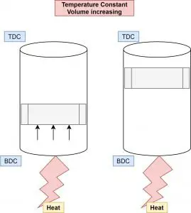
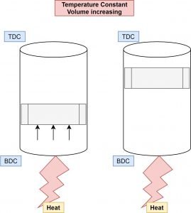
Isothermal expansion is increasing volume with a constant temperature of the system.

Isothermal – temperature constant

Expansion – Increasing volume

Isothermal Process : Expansion
Isothermal Expansion

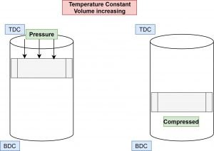
Let’s consider the piston-cylinder arrangement for understanding if the piston moves from BDC (Bottom dead center) to TDC (Top dead center) with a constant temperature of the gas. This isothermal process is considered as Isothermal expansion.

Isothermal compression

Isothermal compression is decreasing volume with a constant temperature of the system.

Isothermal – temperature constant

Compression – decreasing volume

piston cylinder 2
Isothermal Compression

Let’s consider another condition if the piston is moving from TDC to BDC (Bottom dead center) with a constant temperature of the gas. This isothermal process is considered Isothermal compression.

Isothermal vs adiabatic

Isothermal means Constant Temperature.

Adiabatic means Constant heat energy.

Some conditions for an isothermal process are :

  • The temperature should remain constant.
  • The variation must be happening at a slow rate.
  • Specific heat of the gas is infinite.

Some basic conditions for adiabatic are as below :

  • No heat transfer happens in adiabatic.
  • The variation must happen at a very speedy.
  • The specific heat of gas is 0 (Zero).

Isothermal calorimetry

It is one technique to find thermodynamic parameters’ interaction in a chemical solution. Using isothermal calorimetry, one can find binding affinity, binding stoichiometry, and enthalpy changes between two or more molecules interactions.

Isothermal amplification

It is one of the techniques used for pathogen monitoring. In this techniques, the DNA is amplified with keeping sensitivity higher than benchmark polymerase chain reaction (PCR)

Isothermal nucleic acid amplification

Isothermal amplification of nucleic acids is a technique that is efficient and faster accumulating nucleic acid at the isothermal process. It is a simple and efficient process. Since then, around 1990, many isothermal amplification processes have been developed as alternatives to a polymerase chain reaction (PCR)

Isothermal transformation diagram

An isothermal transformation diagram is used to understand the kinetics of steel. It is also known as the time-temperature- transformation diagram.

375px T T T diagram
Time-temperature- transformation diagram Credit Wikipedia

It is associated with mechanical properties, microconstituents/microstructures, and heat treatments in carbon steels.

Isothermal PV diagram

800px Isothermal PV
Isothermal PV Diagram Credit Wikipedia

Isothermal process example

Isothermal is a process in which the system’s temperature remains unchanged or constant.

We can take the example of a refrigerator and heat pump. Here, in both cases, the heat energy is removed and added, but the system’s temperature remains constant.

Examples: Refrigerator, heat pump

Isothermal work

We have used the PV diagram above paragraph. If we want to write work done formula for it. We should consider the area under the curve A-B-VA-VB. The Work done for this integral can be given as,

W= nRT lnfrac{{Vb}}{Va}

Here in the equation,

n is the number of moles

R is gas constant

T is the temperature in kelvin

Isothermal layer

An isothermal layer term is used in atmospheric science. It is defined as a vertical layer of air or gas with constant temperature throughout height. This situation is happening at the troposphere’s low level in various advection situations.

Isothermal PCR

The full form of PCR is a polymerase chain reaction. This reaction is used in isothermal amplification techniques to amplify DNA.

Isothermal process equation

If we consider universal gas law, then the equation is given as below,

PV = nRT

Now, here this is in isothermal process, so T = Constant,

PV = constant

The above equation holds good for a closed system containing ideal gas.

We have discussed the work done earlier. We can consider that equation for the isothermal process. As we know from figure Vb is the final volume, and Va is the initial volume.

W= nRT lnfrac{{Vb}}{Va}

Isothermal expansion of an ideal gas

  • Isothermal – the temperature is constant.
  • Expansion – the volume is increasing.

It means that isothermal expansion increases volume with a constant temperature of the system.

In this condition, the gas is doing work, so the work will be negative because the gas applies energy to increase in volume.

The change in internal energy is also zero ΔU = 0 (Ideal gas, Constant temperature)

Wrev = -int_{Va}^{Va}P dV

Wrev = -int_{Va}^{Va}frac{nRT}{V} dV

Wrev = -nRTlnleft | frac{Vb}{Va} right |

Isothermal reversible expansion

This topic is covered in explaining the isothermal expansion of ideal gas.

Isothermal reaction

A chemical reaction occurring at one temperature, or we can say at a constant temperature, is an isothermal reaction. There no need for temperature change to continue reaction to end.

Isothermal irreversible expansion

An irreversible process is a real process we face in reality almost all the time. The system and its surrounding cannot be restored to their initial states.

Isothermal system

We have discussed the isothermal system in expansion and compression if we take piston-cylinder arrangement.

There are some assumptions for this system like,

  • There is no friction between piston and cylinder
  • There no heat or work loss from the system
  • The internal energy of the system should be constant throughout the isothermal process.

If we supply heat at the bottom of the cylinder, then the piston will move from BDC to TDC, as shown in Figure. It is an isothermal expansion. Similarly, in isothermal compression reverse, as we have explained earlier. This complete system is isothermal.

Isothermal bulk modulus

Bulk modulus is reciprocal of compressibility.

B(isothermal) = -frac{Delta P}{frac{Delta V}{V}}

Here, the term is the isothermal bulk modulus. It can be defined as the ratio of change in pressure to change in volume at a constant temperature. It is equal to P (pressure) if we solve the above equation.

Isothermal internal energy

We have discussed earlier that the constant temperature process’s internal energy remains constant.

Isothermal compressibility coefficient

The isothermal compressibility coefficient can be taken as the change of volume per unit change in pressure. It is also known as oil compressibility. It is widely used in resource estimation of oil or gas in petroleum study.

C(isothermal) = -frac{1}{V}cdot frac{Delta P}{Delta V}

Isothermal heat transfer

The expansion and compression process at constant temperature work on the principle of zero degradation energy. If the temperature is constant, then internal energy change and enthalpy change are zero. So, heat transfer is the same as work transfer.

If we heat the gas in any cylinder, then the gas’s temperature will increase. We want a system at a constant temperature, so we have to put one sink (cold source) to reject gained temperature.

Suppose we consider a cylinder with a piston. The gas will expand in the cylinder, and the piston gives displacement work due to getting heated. The temperature will stay constant in this case also.

Isothermal atmosphere

It can be defined as the there is no change in temperature with height in the atmosphere, and the pressure is decreasing exponentially with moving upward. It is also known as exponential atmosphere. We can say that the atmosphere is in hydrostatic equilibrium.

In this type of atmosphere, we can calculate the thickness between two adjacent heights with the equation given below,

Z2-Z1 =frac{RT}{g} lnfrac{P1}{P2}

Where,

Z1 & Z2 are two different heights,

P1 & P2 are Pressures at Z1 & Z2, respectively,

R is gas constant for dry air,

T is the virtual temperature in K,

g is gravitational acceleration in m/s2

Isothermal surface

Suppose we consider any surface flat, circular, or curvature, etc. If all the points on that surface are at the same temperature, then we can say that the surface is isothermal.

Isothermal conditions

As my word, we know that the system’s temperature must stay constant in this isothermal process. To keep the temperature constant, the system is free to change other parameters like pressure, volume, etc. It is also possible during this process, the work-energy and heat energy can be changed, but the temperature remains the same.

Isothermal zone

This word is generally used in atmospheric science. It is a zone in the atmosphere where the relative temperature is constant at some kilometer height. Generally, it is in the lower part of the stratosphere. This zone provides convenient aircraft conditions because of its constant temperature, general access to clouds and rains, etc.

Isothermal lines

This word is used in geography. Suppose we draw a line on a map of the earth for connecting different places whose temperature is the same or near to the same. It is known as an isothermal line in general.

Here, each point reflects the particular temperature for reading taken in a period of time.

Isothermal belt

In 1858 Silas McDowell of Franklin, given this name for western North Carolina, Rutherford, and Polk countries. This term is used for a season in these zones when one can grow fruits, vegetables, etc., easily due to temperature consistency.

Isothermal vs isobaric

Isothermal – temperature constant

Isobaric – Pressure constant

all process
Isobaric, Isothermal and Adiabatic processes in PV Diagram

Let’s compare both processes for work done. According to the figure, you can notice both processes. As we know, that work done is an area under the integral. In the figure, we can easily see that the isobaric process area is more so obviously, work done more in isobaric. There is some condition for it. The initial pressure and volume should be the same. This is not true because we never get work during isobaric in any of the thermodynamic cycles. This topic is logical.

The correct answer depends on the type of condition that volume is increased or decreased in the process.

Isothermal vs isentropic

Isothermal – temperature constant

Isentropic – Entropy constant

Let’s consider the compression process to understand it,

In isothermal compression, the piston is compressing gas very slowly. As much slowly to maintain the constant temperature of the system.

Whereas in the case of isentropic, there should be no heat transfer possible between the system and surrounding. The isentropic compression will occur without heat transfer with constant entropy.

The isentropic process is similar to adiabatic, where there is no heat transfer. The system for the isentropic process should be well insulated for heat loss. The isentropic compression process always gives more work output due to no heat loss.

FAQs

Is there heat transfer in the Isothermal process?

Answer: Yes,    now the question is why and how?

Let’s consider a piston-cylinder example to understand it,

If heat is supplied to the bottom of the cylinder. The temperature will be maintained constant, and the piston will move. Either expansion or compression process. The heat is transferred, but the system’s temperature will stay the same as it is. This is why during the Carnot cycle, heat is added at a constant temperature.

Why Isothermal process is very slow?

It is necessary that the Isothermal process occurs slowly. Now see, the heat transfer is possible by keeping the system’s temperature constant. It means there is a thermal equilibrium of the system with the body. The process’s timing is slow to keep this thermal equilibrium and constant temperature. The time required for effective heat transfer will be higher, making the process slow.

Isothermal process example problems

There are many applications in day-to-day life with a constant temperature. Some of them are explained as below,

  • The temperature inside the refrigerator is maintained
  • It is possible to melt the ice by keeping the temperature constant at 0°C
  • The phase change process occurs at a constant temperature, evaporation, and condensation
  • Heat pump which works opposite to refrigeration

What are some real-life examples of an Isothermal process?

There is a huge number of example can be possible for this question. Kindly refer above questions.

Any phase change process occurring at constant temperature is an example of an isothermal process.

Evaporation of water from sea and river,

Freezing of water and melting of ice.

Why does Isothermal process be more efficient than the adiabatic process?

Let’s consider the reversible process. If the process is expansion, then the isothermal process’s work is more than adiabatic. You can notice by a diagram. The work done is an area under the curve.

Suppose the process is compression, then opposite to the above sentence. The work done in the adiabatic process is more.

To judge this question depends on every condition. As per the above condition, the isothermal process is more efficient than the adiabatic.

What will be the specific heat for an Isothermal process an adiabatic process, and why?

The specific heat can be defined as the amount of heat is required to raise the temperature of a substance by 1 degree.

Q = m Cp Delta T

If the process is the constant temperature, the ΔT = 0, so the specific heat is undefined or infinite.

Cp = Infinite  (if temperature is constant)

For adiabatic process, the heat transfer is not possible , Q = 0

Cp = 0 (heat transfer is 0)

In an Isothermal process, the change in internal energy is 0 Why?

Internal energy is the function of the kinetic energy of the molecules.

The temperature indicates the average kinetic energy of molecules associated with the system.

If the temperature remains constant, then there is no change in kinetic energy. Hence, the internal energy remains constant. The change in internal energy is zero.

What is more efficient Isothermal compression or isentropic compression, And why?

The isentropic process occurs at constant entropy with no heat transfer. This process is always ideal and reversible. In the isentropic compression process, the system’s internal energy is increasing as there is no possibility of heat transfer between the system and surrounding.

In isothermal compression, the process occurs very slowly as the temperature and internal energy stay constant. There is heat transfer between the system and the surrounding.

That’s why the isentropic compression process is more efficient.

Does an Isothermal process have an enthalpy change?

We can understand it clearly by the equation of enthalpy.

Enthalpy H is given as below,

Change in enthalpy = change in internal energy + change in PV

For constant temperature process,

Change in internal energy = 0,

Change in PV = 0.

That’s why to Change in enthalpy= 0

Why is an adiabatic curve steeper than an Isothermal curve?

In the adiabatic process, the system’s temperature is increasing during compression. It is decreasing during expansion.  Due to this, this curve crosses the isothermal curve at a certain point in the diagram.

In isothermal, there is no change of temperature. The curve will not become steeper like adiabatic.

What would happen if I increase the volume of a system in an Isothermal process with external energy?

 Suppose you increase the volume of the system.  You want the system to be isothermal. You have to make another arrangement for maintaining temperature. The increasing of the volume decreases the pressure.

What is so special about the word “reversible” in an Isothermal or an adiabatic process?

The first law of thermodynamics states that both of the processes sketched on the PV diagram are reversible mean. The system will come to its initial stage to stay in equilibrium.

Why Isothermal and adiabatic in Carnot engine?

The Carnot cycle is the most efficient in thermodynamics. The reason behind it is all the process in the cycle is reversible.

Carnot tried to transfer energy between two sources at constant temperature (Isothermal).

He tried to maximize the expansion work and minimize the required compression. He selected an adiabatic process for it.

For more articles, Click here

Reynolds Number: 21 Important Facts

Reynolds Number

Content

Reynolds number definition

“The Reynolds number is the ratio of inertial forces to viscous forces.”

The Reynolds number is a dimensionless number used to study the fluid systems in various ways like the flow pattern of a fluid, the flow’s nature, and various fluid mechanics parameters. The Reynold’s number is also important in the study of heat transfer. There are much correlation developed, including Reynold’s number in fluid mechanics, tribology and heat transfer. The preparation of various medicines in pharmacy required Reynold’s number study.

It is actually a representation and comparison of inertia force and viscous force.

Reynolds number equation

The dimensionless Reynold’s number represents whether the flowing fluid would be laminar flow or turbulent flow, considering to some properties such as velocity, length, viscosity, and flow type. The Reynold’s number has been discussed as follow:

The Reynold’s number is generally termed as the inertia force ratio to viscous force and characterize the flow nature like laminar, turbulent etc. Let’s see by the equation as below,

Re= \\frac{Inertia force}{viscous force}

Inertia force =\\rho A V^{2}

Viscous force = \\frac{\\mu V A}{D}

By putting the inertia force and viscous force expression in Reynold’s number expression, we get

Re = \\frac{\\\\rho V D}{\\mu }

In above equation,

Re = Reynold’s number (Dimensionless number)

? = density of fluid (kg / m3)

V = velocity of flow ( m/ s )

D = Diameter of flow or pipe/ Characteristics length ( m )

μ = Viscosity of fluid (N *s /m2)

Reynolds number units

The Reynold’s number is dimensionless. There is no unit of Reynolds number.

Reynolds number for laminar flow

The identification of flow can be possible by knowing the Reynold’s number. The Reynold’s number of laminar flow is less than 2000. In an experiment, if you get a value of Reynold’s number less than 2000, then you can say that the flow is laminar.

Reynolds number of water

The equation of Reynold’s number is given as

Reynolds number= \\frac{Density of fluid \\cdot velocity of flow\\cdot Diameter of flow/Length}{Viscosity of fluid}

If we analyze the above equation, the Reynolds number’s value depends on the density of fluid, velocity of flow, the diameter of flow directly and inversely with the viscosity of the fluid. If the fluid is water, then the density and viscosity of water are the parameters that directly depend on water.

laminar to turbulent convertion
laminar to turbulent
Image credit : brewbooks from near Seattle, USA, Laminar to Turbulent – Flickr – brewbooksCC BY-SA 2.0

Reynolds number for turbulent flow

Generally, the Reynolds number experiment can predict the flow pattern. If the value of Reynold’s number is >  4000, then the flow is considered as turbulent nature.

Drag Coefficient (Cd) vs Reynolds number (Re) in various objects

Renolds Number
Image credit : “File:Drag Coefficient (Cd) vs Reynolds number (Re) in various objects.png” by Welty, Wicks, Wilson, Rorrer. is licensed under CC BY-SA 4.0

Reynolds number in a pipe

If the fluid is flowing through the pipe, we want to calculate Reynold’s number of fluid flowing through a pipe. The other all parameters depends on the type of fluid, but the diameter is taken as pipe Hydraulics diameter  DH (For this, the flow should be properly coming out from the pipe)

Reynolds number= \\frac{Density of fluid \\cdot velocity of flow\\cdot Hydraulic Diameter of flow/Length}{Viscosity of fluid}

Reynolds number of air

As we have discussed in Reynold number for water, The Reynold number for air directly depends on air density and viscosity.

Reynolds number range

Reynold’s number is the criteria to know whether the flow is turbulent or laminar.

If we consider the flow is internal then,

If Re < (2000 to 2300) flow is considered laminar characteristics,

 Re > 4000 represents turbulent flow

If Re’s value is in between (i.e. 2000 to 4000)  represents transition flow.

Reynolds number chart

The moody chart is plotted between Reynolds number and friction factor for different roughness.

We can find the Darcy-Weisbach friction factor with Reynold number. There is an analytical correlation developed to find the friction factor.

Reynolds number
Reynold’s number in Moody Diagram Wikipedia
Credit Original diagram: S Beck and R Collins, University of Sheffield (Donebythesecondlaw at English Wikipedia) Conversion to SVG: Marc.derumauxMoody ENCC BY-SA 4.0

Reynolds number kinematic viscosity

The kinematic viscosity is given as,

Kinematic viscosity = \\frac{Viscosity of fluid}{Density of fluid}

The Equation of Reynold’s number,

Reynolds number= \\frac{Density of fluid \\cdot velocity of flow\\cdot Hydraulic Diameter of flow/Length}{Viscosity of fluid}

The above equation is formed as below if write it in the form of kinematic viscosity,

[Reynolds number= \\frac{velocity of flow\\cdot Hydraulic Diameter of flow/Length}{Kinematic Viscosity of fluid}

Re =\\frac{VD}{\ u }

Reynolds number cylinder

If the fluid is flowing through the cylinder and we want to calculate Reynold number of fluid flowing through the cylinder. The other all parameters depends on the type of fluid, but the diameter is taken as Hydraulics diameter DH (For this, the flow should be properly coming out from the cylinder)

Reynolds number mass flow rate

We then analyse the Reynold’s number equation if we want to see the relationship between the Reynold’s number and mass flow rate.

Re = \\frac{\\rho V D}{\\mu }

As we know from the continuity equation, the mass flow rate is expressed as below,

m =\\rho \\cdot A\\cdot V

By putting values of mass flow rate in the Reynolds number equation,

Re =\\frac{m\\cdot D}{A\\cdot \\mu }

It can be clearly noted from the above expression that the Reynold’s number has a direct relation with the mass flow rate.

Laminar vs turbulent flow Reynolds number | Reynolds number laminar vs turbulent

Generally, in fluid mechanics, we are analyzing two types of flow. One is the laminar flow which occurs at low velocity, and another is the turbulent flow which generally occurs at high velocity.  Its name describes the laminar flow as the fluid particles flow in the lamina (linear) throughout the flow. In turbulent flow, the fluid travels with random movement throughout the flow.

Let’s understand this important point in detail,

Laminar and Turbulent
Reynolds number for Laminar and Turbulent flow
Image credit :JoseasorrentinoTransicion laminar a turbulentoCC BY-SA 3.0

Laminar Flow

In laminar flow, the adjacent layers of fluid particles do not intersect with each other and flows in parallel directions is known as laminar flow.

In the laminar flow, all fluid layers flow in a straight line.

  • There possibility of occurrence of laminar flow when the fluid flowing with low velocity and the diameter of the pipe is small.
  • The fluid flow with a Reynold’s number less than 2000 is considered laminar flow.
  • The fluid flow is very linear. There is the intersection of adjacent layers of the fluid, and they flow parallel to each other and with the surface of the pipe.
  • In laminar flow, the shear stress only depends on the fluid’s viscosity and independent of the density of the fluid.

Turbulent Flow

The turbulent flow is opposite to the laminar flow. Here, In fluid flow, the adjacent layers of the flowing fluid intersect each other and do not flow parallel to each other, known as turbulent flow.

The adjacent fluid layers or fluid particles are not flowing in a straight line in a turbulent flow. They flow randomly in zigzag directions.

  • The turbulent flow is possible if the velocity of the flowing fluid is high, and the diameter of the pipe is larger.
  • The value of the Reynold’s number can identify the turbulent flow. If the  value of Reynold’s number is more than 4000, then the flow is considered a turbulent flow.
  • The flowing fluid does not flow unidirectional. There is a mixing or intersection of different fluid layers, and they do not flow in parallel directions to each other but intersecting each other.
  • The shear stress depends on its density in a turbulent flow.

Reynolds number for flat plate

If we analyse the flow over a flat plate, then the Reynolds number is calculated by the flat plate’s characteristics length.

Re = \\frac{\\rho V L}{\\mu }

In the above equation, Diameter D is replaced by L, which is the characteristics length of flow over a flat plate.

Reynolds number vs drag coefficient

Suppose the Reynold’s number’s value is lesser than the inertia force. There is a higher viscous force getting dominance on inertia force.

If the fluid viscosity is higher, then the drag force is higher.

Reynolds number of a sphere

If you want to calculate it for this case, the formula is

Re = \\frac{\\rho V D}{\\mu }

Here, Diameter  D is taken as Hydraulics diameter of a sphere in calculations like cylinder and pipe.

What is Reynolds number?

Reynold’s number is the ratio of inertia force to viscous force. Re indicates it. It is a dimensionless number.

Re= \\frac{Inertia force}{viscous force}

Significance of Reynolds number | Physical significance of Reynolds number

Reynold number is nothing but comparing of two forces. One is the inertia force, and the second is the viscous force. If we take both force ratio, it gives a dimensionless number known as Reynold number. This number helps to know flow characteristics and know which of the two forces impacts more on flow. The Reynold number is also important for flow pattern estimation.

   Viscous force -> Higher -> Laminar flow -> Flow of oil

   Inertia Force -> Higher -> Turbulent flow > Ocean waves

Reynolds experiment

Osborne Reynolds first performed the Reynolds experiment in 1883 and observe the water motion is laminar or turbulent in pattern.

This experiment is very famous in fluid mechanics. This experiment is widely used to determine and observe the three flow. In this experiment, the water flows through a glass tube or transparent pipe.

The dye is injected with water flow in a glass tube. You can notice the flow of dye inside the glass tube. If the dye has a different colour than water, it is clearly observable. If the dye is flowing inline or linear, then the flow is laminar. If it dye shows turbulence or not flowing in line, we can consider the turbulent flow. This experiment is simple and informative for students to learn about flow and Reynolds number.

Critical Reynolds number

The critical Reynolds number is the transition phase of laminar and turbulent flow region. When the flow is changing from laminar to turbulent, the Reynold’s number reading is considered a critical Reynold’s number. It is indicated as ReCr.  For every geometry, this critical Reynold’s number will be different.

Conclusion

Reynolds number is important terms in the field of engineering and science. It is used in study of flow, heat transfer, pharma etc. We have elaborated this topic in detail because of its importance. We have included some practical questions and answers with this topic.

For more articles on the related topics click here , Please find below

Volumetric Flow Rate: 7 Important Concepts

volume flow rate

Volume flow rate

The volumetric flow rate (volume flow rate, rate of fluid flow) is defined as the fluid volume passed per unit time through fluid flowing body such as pipes, channel, river canal etc.); In hydrometry, it is acknowledged as discharge.

Generally, the Volume flow rate is denoted by the symbol Q or V. The SI unit is m3/s. The cubic centimetres per minute is also used as unit of volume flow rate in small scale flow

Volumetric flow rate is also measured in ft3/s or gallon/min.

Volumetric flow rate is not the similar as volumetric flux, as an understanding by Darcy’s law and shown by the symbol q, the units of m3/(m2·s), that is, m·s−1(velocity). In calculation, the integration of flux over area computes the volumetric flow rate.

Volumetric flow rate
Volume flow rate

In the meantime, it is scalar quantity, as it is the time derivative of volume only. The variation in volume flows thru an area would be zero for steady state flow situation.

Volumetric flow rate equation

Volumetric flow rate expresses the volume that those molecules in a fluid flow occupy in a given time.

Q (V)  = A v

The given equation is only valid for flat, plane cross-sections. Generally, in curved-surface the equation turn out to be surface integrals.

Q (V) = volumetric flow rate (in m3/s), l/s, l/min (LPM)

A – Cross sectional area of pipe or a channel (m2)

v – Velocity (m/s, m/min, fps, fpm etc.

As gases are compressible, volumetric flow rates can change substantially when subjected to pressure or temperature variations; that is why it is important to design thermal equipment or processes and chemical processes.

Volumetric flow rate symbol

The symbol of the volumetric flow rate is given as V or Q

Volumetric flow rate units

The unit of volumetric flow rate is given as (in m3/s), l/s, l/min (LPM), cfm, gpm

Volumetric flow rate to mass flow rate

The variation between mass flow and volumetric flow relates to the density of what you are moving. We focus on which one we focus on is determined by the concern of the problem. For example, if we are developing a system for use in a hospital, it could be moving water or moving blood. Since blood is denser than water, the same volumetric flow would result in a higher mass flow if the fluid was blood than if it was water. Conversely, if the flow resulted in a specific amount of mass being moved in a specific time, more water would be moved than blood.

Volumetric flow rate to velocity

If we see the volumetric flow unit, it is m3/s, and the unit of velocity is m/s. So if we want to convert volumetric flow rate into velocity. We divide the volumetric flow rate by the cross-sectional area from which fluid is flowing. Here, we have to take an area of a cross-section of pipe from which liquid is flowing.

In short, if we want to find a velocity from volumetric flow, we have to divide the volumetric flow by cross-section area of pipe or duct from which it is flowing.

Unit of volumetric flow m3/s

Unit of area m2

Unit of velocity =

Unit  of velocity =(m^3/s)/m^2 =m/s

Volumetric flow rate to molar flow rate

You know Molar flow rate (n) is defined as the no. of moles in a solution/mixture that pass thru the point of measurement per unit of time

Whereas, Volumetric flow (V) rate is the volume of fluid pass thru the measurement point per unit time.

Both these are connected by an equation

? (density of the fluid) = n/V

FAQs

What is meant by flow rate?

Let’s first, we need to know that there are two types of flow rates: mass and volumetric.

Both flow rates are used to know how much fluid passes through a pipe section per unit of time. The mass flow rate measures the flowing mass, and the volumetric flow rate is measuring the volume of flowing fluid.

If the fluid is incompressible in nature, like liquid water at normal conditions, both quantities are proportional, employing the fluid’s density.

These flow rates are helpful in many important fluid dynamics calculations, so I am delighting one of the application: continuity equation.

The continuity equation states in a pipe with waterproof walls where an incompressible fluid flows, the volumetric flow rate is constant in all the pipe sections.

Flow rate calculation using pressure

In cases like flow nozzles, venturi and orifice, the flow is depend to ΔP (P1-P2) by the equation:

Q = CD π/4 D22 [2(P1-P2) / ρ(1 – d4) ]1/2

Wherever:

Q  –> flow in m3/s

CD –> discharge coefficient = A2/A1

P1 and P2 –> in N/m2

ρ –>  fluid density in unit kg/m3

D2 –> The inside diameter of nozzles (in m)

D1 –>  The inlet and outlet pipe diameter (in m)

and d = D2/D1 diameter ratio

Can I add two different volumetric flow rate of the same gas that came from two different pipes and were measured at different conditions?

If we consider several situations, the answer is yes. Let’s see what those situations are? The pressure in the pipeline should be relatively minimal. There is no change in density because of pressure variation. The flow measuring device should be installed far from the pipe’s junction to avoid beck pressure interference.

When would the maximum volumetric flow rate occur through a pump, And why?

If we consider a centrifugal pump, the pump’s volumetric flow rate is directly proportional to the impeller’s speed and a cube of impeller diameter. So, if we increase the speed for a given pump, we will get a high flow rate. Otherwise, if we concentrate on diameter, we can install a big pump to get a high flow rate. It is also possible to get a high flow rate by installing several pumps in parallel. Remember each pump must develop the same head at the discharge; otherwise, backflow to another pump may occur.

But all those solutions are based on theoretical considerations. If you are supposed to do that in an actual plant, then there must be many constraints that you have to consider!

For example, you should consider the cost of a pump, space consumptions etc.

How do you convert a molar flow rate into a volumetric flow rate?

Both these are connected by an equation

? (density of the fluid) = n/V

Why is it that the inlet’s volumetric flow rate is not equal to that at an exit under steady-state conditions?

If the flow is incompressible and non-reacting, then it can be possible that volumetric flow is not the same as in inlet and outlet. Other might be the law of conservation of mass has to be fulfilled.

Is there a relationship between pressure and volumetric flow rate in the air?

For that relation we may look for “Hagen-Poiseuille relation”, the pipe flow rate is related to pipe size, the fluid properties and ΔP has been explained.

It is derived from Navier-Stokes’s equations, so it is a momentum balance.

∆P=128μLQ/(πd^4 )

ΔP is the pressure drop [Pa]

μ is the fluid viscosity [Pa⋅s]

L equal to pipe length [m]

Q will be the volume flow rate in [m3/s]

d is the dia of pipe [m]

Why does the head of a pump decrease with the volumetric flow rate?

It is actually easier to visualise if you switch them around. As the head that the pump has to work against goes down, the volume that it discharges goes up (for a centrifugal pump at a given speed).

Essentially, the pump imparts energy to the fluid at a fixed rate (ignoring efficiencies for a moment). That energy can be produced as potential energy (head) or kinetic energy (volumetric flow rate), or any combination up to the total amount of energy.

It’s similar to pushing a heavyweight up a ramp. The steeper the ramp, the less weight you can push-ups it.      

What is the difference between volumetric flux and velocity in porous medium flow?

Volumetric flux is the volume of fluid flowing through a unit surface in unit time, whereas velocity is the distance travelled by the fluid from two-unit time points.

The unit of volumetric flux and velocity is the same.

In the case of a porous medium, the volumetric flux will be less than or equal to(less likely to be equal) than the velocity of the flow, depending on the medium’s porosity.

Does waterfall down a vertical pipe accelerate at g? I want to calculate the volumetric flow rate of water at the bottom of an 85m tall vertical pipe?

It depends on the friction factor of the pipe. The friction factor depends on the roughness of the pipe and Reynold number. The friction is resistance to the water flow. It means that friction is reducing the acceleration. If we consider friction is zero, then acceleration is equal to g.

A continuous flow of water would be established along the pipe. Thus, it would not matter, as the average velocity would be the same as at the top of the pipe or midway.

If you want to calculate the volumetric flow rate of water at the bottom of the pipe, you need to calculate the velocity and multiply by the pipe’s cross-sectional area.

if we ignore friction, the average velocity at the bottom is given by

v=√2gh

The loss of energy can be found in the moody diagram.

How does a valve affect volumetric flow rate without violating conservation of mass?

As we know that volumetric flow rate is the multiplication of velocity and cross-sectional area from which the flow is flowing. In the case of the valve, the cross-sectional area is affected. The cross-sectional area’s change is varying the velocity of flowing fluid, but the overall volume flow rate remains the same. The conservation of mass principle is satisfied. As per Bernoulli’s principle, we know that reducing cross-sectional area kinetic energy is converted into pressure energy.

flow
Area, Velocity and Pressure relationship

foe more article click here
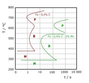
Continuity Equation: 7 Important Concepts

stream tube 300x269 1

List of Content

  • Continuity equation
  • Continuity equation differential form
  • Continuity equation for incompressible flow
  • Continuity equation for two-dimensional coplanar flow
  • Continuity equation example
  • Question & Answers
  • MCQ
  • Conclusion

Continuity equation

The fluid flowing through the stream tube is assumed to the ideal fluid. There is no flow occurs across the streamline. It means that fluid enters at one end and leave at the other end there is no in-between outlet. Consider flow condition at inlet cross-section 1-1 as below,

stream tube
Stream tube
Parameters Inlet section 1-1 Outlet section 2-2
Cross-sectional area A A+dA
Average fluid density ? ?+d?
Mean flow velocity V V+dV

The fluid mass which flows between this two considered sections is given by following formula,

dm = (A V ? dt ) – ( A +  dA ) ( V+ dV ) ( ? + d? ) dt            Eq … 1

by simplifying above equation we get ,

dm/dt = – (A V d? + V ? dA + A ? dV)                                      Eq … 2

As we know that steady flow means constant mass flow rate, it means here dm/dt = 0.  Now Eq. 2 turned as below,

(A V d? + V ? dA + A ? dV) = 0                                                   Eq … 3

Now, divide Eq. 3 with ? A V, equation will be like,

( d?/? ) + ( dA/A ) + ( dV/V ) = 0                                          Eq … 4

d ( ? A V ) = 0                                                                                   Eq … 5

? A V = Constant                                                                             Eq … 6

Here, the Eq. 6 makes us know that the mass of fluid passing through stream tube is constant at every section.

Suppose the fluid is incompressible (liquid) then the density of fluid will not change at any point. It means that fluid density is constant.

A V = Constant

A1 V1 = A2 V2                                                                                                                           Eq … 7

Eq. 7 represents the continuity equation for steady incompressible flow inside the stream tube. The continuity equation gives a basic understanding of area and velocity. The cross-sectional area’s change affects the velocity of flow inside the stream tube, pipe, hollow channel, etc. Here, the exciting thing is a product of velocity and cross-sectional area. This product is constant at any point in the stream tube. The velocity is inversely proportionate to the cross-section area of the stream tube or pipe.

Continuity equation differential form

To derive the differential form of the continuity equation, consider an object as shown in the figure. The dimensions are dx, dy, and dz. There are some assumptions for this formation. The mass of fluid is not created or destroyed, no cavity or bubbles in fluid ( continuous flow). We consider dx in the x-direction, dy in y, and dz in z directions for easiness in derivation.

If u is the velocity of fluid flow as per shown face in the figure. It is assumed that velocity is uniform throughout the face cross-sectional area. The fluid velocity at surface 1-2-3-4 is u. now; the surface 5-6-7-8 is a dx distance far from 1-2-3-4. So, the velocity at 5-6-7-8 is given as

u+∂u/∂x  dx
Differential form of the continuity equation

As we know that there change in density by using compressible fluid. If the compressible fluid passes through an object, the density will change.

The mass flow entering the object is given as

Mass flow = ? A V

Mass flow rate = ? A V dt

The fluid entering on 1-2-3-4

Inlet fluid = density ( area * velocity) dt

Inlet fluid= ρ u dy dz dt

Eq … 1

The fluid leaving from 5-6-7-8

Outlet fluid

outlet fluid= [ρu+ ∂/∂x  (ρu)dx]  dy dz dtt

Eq … 2

Now, the difference between inlet fluid and outlet fluid is mass stayed in x direction flow.

= ρ u dy dz dt- [ρu+ ∂/∂x  (ρu)dx]  dy dz dt
=  - ∂/∂x  (ρu)dx  dy dz dt

Eq … 3

Similarly, we consider mass of fluid in y and z direction is given as below,

= - ∂/∂y  (ρv)dx  dy dz dt

Eq … 4

=  - ∂/∂z  (ρw)dx  dy dz dt

Eq … 5

Here, the v and w are the velocities of fluid in y and z directions, respectively.

For the mass flow of fluid in all three directions, axes are given by the addition of Eq. 3, 4, and 5. It is given as below total fluid mass,

= -[∂/∂x  (ρu)+ ∂/∂y  (ρv)+ ∂/∂z  (ρw)]  dx  dy dz dt

Eq … 6

The rate of change of mass within the object is given by,

∂m/∂t  dt=  ∂/∂t  ( ρ ×volume )  dt=   ∂ρ/∂t  dx dy dz dt

Eq … 7

As per understanding of mass conservation Eq. 6 equal to Eq. 7

-[∂/∂x  (ρu)+ ∂/∂y  (ρv)+ ∂/∂z  (ρw)]   dx  dy dz dt=  ∂ρ/∂t  dx dy dz dt

Solving the above equation and simplifying it, we get,

∂ρ/∂t+∂/∂x (ρu)+ ∂/∂y  (ρv)+ ∂/∂z  (ρw)=0

Eq … 8

Eq. 8 is. Continuity equation for general flow. It may be steady or unsteady, compressible or incompressible.

Continuity equation for incompressible flow

If we consider flow is steady and incompressible. We know that in the case of steady flow ??/?t = 0. If the flow is incompressible, then density ? remains constant. So, by considering this condition, Eq. 8 can be written as,

∂u/∂x+ ∂v/∂y  + ∂w/∂z  =0

Continuity equation for two-dimensional coplanar flow

In two-dimensional flow, there are two directions x and y. So, u velocity in x-direction and v velocity in the y-direction. There is no z-direction, so velocity in the z-direction is zero. By considering these conditions, the Eq. 8 turned as below,

∂/∂x (ρu)+ ∂/∂y  (ρv)=0

Compressible flow

∂u/∂x+ ∂v/∂y  =0 

Incompressible flow, Density is zero

Continuity equation example

There is flow air through the pipe at the rate of 0.25 kg/s at an absolute pressure of 2.25 bar and temperature of 300 K. If the flow velocity is 7.5 m/s, then what will be the pipe’s minimum diameter?

Data,

m = 0.25 kg/s,

P = 2.25 bar,

T = 300 K,

V = 7.5 m/s,

Calculate the density of air,

P = ? R T

? = P / RT

? = ( 2.25 * 105 )/ ( 287 * 300 ) = 2.61 kg/m3

Mass flow rate of air,

m = ? A V

A = m / ? V

A = 0.25 / ( 2.61* 7.5 ) = 0.012 m2

As we know that area,

A = π D2 / 4

D= √((A*4)/π)
D= √((0.012*4)/3.14)

D = 0.127 m = 12.7 cm

A jet of water in upward direction is leave nozzle  tip at the velocity of 15 m/s. The diameter of nozzle is 20 mm. suppose there is no energy loss during operation. What will be the diameter of water jet at 5 m above from the nozzle tip.

Ans.

First of all, imagine the system; the flow is in a vertical direction.

Data,

V1 = velocity of jet at the nozzle tip

V2 = velocity of jet at 5 m above from nozzle tip

Similarly, areas A1 and A2.

We have general equation of motion as below,

〖V2〗^2-〖V1〗^2=2 g s
〖V2〗^2-〖15〗^2=2*(-9.8)*5

V2 = 11.26 m/s

Now , apply continuity equation,

A1 V1 = A2 V2

A2 = (A1 V1)/ V2

A2=  ((π/4)* (0.02)^2* 15)/11.26=4.18* 10^-4  m^2
π/4*〖d2〗^2  =4.18* 10^-4 m^2

Diameter = 0.023 m = 23 mm

Questions & Answers

What is the difference between the continuity equation and the Navier Stokes equation?

Fluids, by definition, can flow but it is fundamentally incompressible in nature. The continuity equation is a consequence of fact that what goes into a pipe/ hose must also release out. So, in the end, the area times the velocity at the end of a pipe/hose must remain constant.

In a necessary consequence if the area of the pipe/hose decreases, the fluid’s velocity must also increase to keep the flowrate constant.

While the Navier-Stokes equation describes the relations in between velocity, pressure, temperatures, and density of a moving fluid. This equation usually coupled with various differential equation forms. Usually, it’s pretty complex to solve analytically.

What is the continuity equation based on?

The equation of continuity says that the volume of fluid entering into the pipe of any cross-section should be equal to the volume of fluid leaving the other side of the cross-sectional area, which means the rate of flow rate should be constant and should follow the relation-

Suppose the fluid is incompressible (liquid), then the fluid density will not change at any point. It means that fluid density is constant.

A V = Constant

Flow rate = A1 V1 = A2 V2

What is the continuity equation used for?

Continuity equation has many applications in the field of Hydrodynamics, Aerodynamics, Electromagnetism, Quantum Mechanics. It is an important concept for the fundamental rule of Bernoulli’s Principle, it is indirectly involved in the Aerodynamics principle and applications.

The equation of continuity expresses a local conservation law depending on the context. It is merely a mathematical statement that is subtle yet very powerful concerning the local conservation of specific quantities.

Does the equation of continuity hold for supersonic flow?

Yes, It can be used for supersonic flow. It can be used for other flows like hypersonic, supersonic, and subsonic. The difference is that you have to use the conservative form of the equation.

What is the three-dimensional form of the continuity equation for steady incompressible flow?

If we consider flow is steady and incompressible. We know that in the case of steady flow ??/?t = 0. If the flow is incompressible, then density ? remains constant. So, by considering this condition, Eq. 8 can be written as,

 ∂u/∂x+ ∂v/∂y  + ∂w/∂z  =0

What is the 3D form of the continuity equation for steady compressible and incompressible flow?

In two-dimensional flow, there are two directions x and y. So, u velocity in x-direction and v velocity in the y-direction. There is no z-direction, so velocity in the z-direction is zero. By considering these conditions, the Eq. 8 turned as below,

∂/∂x (ρu)+ ∂/∂y  (ρv)=0
 ∂u/∂x+ ∂v/∂y  =0

Multiple Choice Questions

Which one of the following is a form of continuity equation?

  1. v1 A1 = v2 A2
  2. v1 t1 = v2 t2
  3. ΔV / t
  4. v1 / A1 = v2 / A2

What does the continuity equation give the concept about the movement of an ideal fluid?

  1. As the cross-sectional area increases, the speed increases.
  2. As the cross-sectional area decreases, the speed increases.
  3. As the cross-sectional area decreases, the speed decreases.
  4. As the cross-sectional area increases, the volume decreases.
  5. As the volume increases, the speed decreases.

The equation of continuity is based on the principle of

a) conservation of mass

b) conservation of momentum

c) conservation of energy

d) conservation of force

Two similar pipe diameters of d converge to obtain a pipe of diameter D. What can be the observation between d and D?. The velocity of flow in the new pipe will be double that in each of the two pipes?

a) D = d

b) D = 2d

c) D = 3d

d) D = 4d

The pipes of different diameters d1 and d2 converge to obtain a pipe of diameter 2d. If the liquid velocity in both pipes is v1 and v2, what will be the flow velocity in the new pipe?

a) v1 + v2

b) v1 + v2/2

c) v1 + v2/4

d) 2(v1 + v2)

Conclusion

This article includes continuity equation derivations with their different form and conditions. Basic examples and questions are given for a better understanding of the concept of the continuity equation.

For more articles with related topics, click here
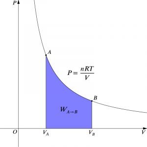
Read more Scientific Principles.