9+ Hydroelectric Energy Examples: Uses And Detailed Facts

450px ThreeGorgesDam China2009 300x186 1

This article discusses about hydroelectric energy examples. If we split the word hydroelectric into parts e get hydro and electric which means electricity produced with the help of water.

Humans have made huge advancements in tapping the energy from renewable sources like sunlight, water, geothermal energy and even wind. Burning fossil fuels was becoming a problem as they are limited resources and we cannot keep depending on it without having an alternate resource. In this article we shall discuss about hydroelectricity or hydroelectric energy.

What is hydroelectric energy?

The name itself suggests that it is the electric energy generated or produced with the help of movement of water.

To produce electricity, electrons flow is necessary. Electron flow between two points takes place when there is a potential difference between those two points. A generator is a device that can produce alternating currents. The alternating current can be converted to DC if needed. We shall discuss in the below section about how electricity can be produced from water movements.

How is electricity generated?

We can generate power/electricity by a device called as generator. It can produce alternating currents. Although generator needs mechanical assistance to do so.

Turbines give the generators the mechanical assistance needed. The turbine shaft rotates which is connected to the generator. This rotary movement is the prime requirement for a generator to be able to produce electricity. Let us discuss about how electricity can be generated from water bodies.
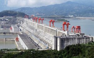
hydroelectric energy examples
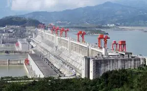
Image: Dam

Image credits: Source fileLe Grand Portage Derivative work: RehmanThreeGorgesDam-China2009CC BY 2.0

How is electricity generated from water bodies?

We know the fact that we cannot produce energy rather we can only convert it from one form to another. The question is how to convert the energy from one to another? In this section we shall read about how tidal energy is converted to electric energy.

The water bodies have immense amount of energy (both potential and kinetic). The dams accumulate a large amount of water in a reservoir and lets the water rush out to other sides through gates situated at a height. This way the potential energy of water is converted to kinetic energy, this kinetic energy of water is used to rotate the turbine blades and indeed the turbine shaft. This way the electricity is generated using tidal energy. There are other ways to tap tidal energy but dams are the most common and highest energy converting structures man has made.

Hydroelectric energy examples

Dams are used to generate a large amount of electricity. There are other ways through which we can generate electricity.

The different examples of hydroelectric energy are given in the section below-

Dams

The most common method of tapping water energy and converting it to electricity. We have already discussed in the above section about how electricity is generated.

Pumped storage

Two reservoirs are used in this method. These reservoirs are located at different heights.

Run of the river

This method does not employ any reservoir, it uses the readily available energy from the river which is flowing downstream.

Tide

The high tides and low tides also contain a large amount of water energy. This energy can also be tapped to produce electricity. The movement of water from one place to another during tides is used to run turbines.

Underground facilities

Underground facilities use water bodies such as water falls to produces electricity.

Tidal stream generators

They look like conventional wind turbines with the only difference being that the stream generators are used in water bodies. The two main designs are also similar to a wind turbine that are horizontal and vertical axis turbines. The blades can adjust their pitch with the movement of tides so as to produce as much power as possible.

Archimedes screws

The name itself suggests that these are screw like structures having helical sections through which the water is drawn upside rotating the turbines.

Floating structures

Floating structures move up and down as the water keeps moving, this up and down motion can be converted into rotary motion of turbine blades.

Tidal kites

Tidal kites belong to a very uncommon method of producing electricity.  The kites are tethered to the water body, they carry a turbine just below the wing. When the kite makes a figure of eight inside the water body the volume of water passing through the turbine becomes maximum.

Offshore hydropower

It is a growing technology which uses tidal or power of waves to generate electricity.

Hydroelectric energy uses

The uses of hydroelectric energy are many. The uses of hydroelectric energy are discusses in the section below-

  • As it is a renewable source of energy, we can produce as much amount of energy as possible.
  • The source of energy is infinite hence no fear of it being exhausted by excessive use.
  • The energy production is a lot cleaner than conventional powerplants which burn coal for producing electricity.
  • It can be used a trustworthy source of electricity during electricity break outs or disruptions
  • Can be used to control floods
  • Can be used for irrigation purposes
  • Can be used for clean drinking water systems
  • Hydroelectric energy is affordable
  • It makes artificial lakes
  • The emissions are next to zero

What are disadvantages of setting up a dam?

There are many advantages of dams but with all the advantages in hand there are several disadvantages too.

Let us discuss about those disadvantages in the section given below-

  • Local people are moved from one place to another because their land will be used to make reservoir and dam.
  • The local vegetation gets submerged in water
  • If not regulated properly, it may lead to man made floods for Example the great flood of Surat in 2006.
  • It affects the groundwater table
  • It displaces a huge amount of water affecting the marine life
  • Reservoirs emit a huge amount of green house gases.
  • It often blocks water to other countries as the rivers flow in several countries at once. But building a dam at one place will block the water coming to another country.

Also Read:

Mig Vs Arc Welding: When To Use What, Comparative Analysis On Different Factors

RK WL GMAW 1

This article discusses about the topic mig vs arc welding. Welding is a fabrication technique in which two or more metals are joined together with the help of heat and pressure.

Different sources of heat provide different amount of heat at the joint. Different amount of heat and pressure will result in welds of different properties. In this article we shall focus on two kinds of welding namely mig welding and arc welding. Let us start our discussion with the definition of welding.

What is welding?

Welding is a fabrication technique used to join two or more metals. This is done with the help of heat and pressure. An optimum amount of both these parameters are needed to provide the weld of desired properties.

If any one of the parameters is not properly regulated then the weld formation will not take place properly and the weld may break due to weakness. Different applications require different types of weld properties, so the sources of heat may be changes in order to make the welding process economical and energy saving.

What is mig welding ?

Mig welding stands for Metal inert gas welding. As the name suggests, this type of welding includes the participation of inert gas like Helium.

Helium protects the weld pool and the bare wire electrode. The welding takes place as a result of arc striking the surface of the work piece. The tip of the electrode is the place where arc takes place. The arc generates enough heat to create a weld pool in the surrounding area. A weld bead is formed which is allowed to cool at room temperature. This weld bead is the desired joint.

mig vs arc welding
Image: Mig welding

Image credits : WeldscientistRK WL GMAWCC BY-SA 4.0

What is Arc welding?

Arc welding as the name suggests uses an arc to fulfil the purpose of welding. The arc is generated by an AC or DC supply. A consumable or non consumable electrode can be used in this process.

There are four types of arc welding which are been discussed in the later section of this article. The heat generated from the arc is used to join the two metals. An arc is formed when there is high voltage passing through the electrode and the electrode is lifted by a very small distance from the work piece disconnecting the circuit. The arc flows through this short distance.

Mig vs arc welding strength

The strength of welds are different for different welding processes. The table below shows the difference between mig welding and arc welding strength.

Mig weldingArc welding
The welding is stronger on thinner materialsThe welding is weaker for thinner materials
The welding is weaker on thick materialsThe welding is stronger for thick materials
Table: MIg VS Arc welding strength

Gasless mig vs arc welding

The comparison between gasless mig vs arc welding is given in the table below

Gasless mig weldingArc welding
No gas is required for shieldingNo shielding is required
Better for both thin and thick sheets of metalsBetter for thick sheets for metals
The set up is expensiveThe set up is cheaper than gasless mig
Table: Gasless mig vs arc welding

Submerged arc welding vs mig welding

The comparison between submerged arc welding and metal inert gas welding is shown in the table below

Submerged Arc weldingMig welding
 Uses continuous feed wireUses continuous feed wire
Uses powdered flux for shieldingUses inert gases like Helium for shielding
Fully automaticSemi automatic
Used for only down handing weldingIt can be used in various positions
Used for very thick metalsUsed for thin plates.
Table: Submerged arc welding vs mig welding

Spray arc welding vs mig

Spray arc weldingMig welding
Molten metal droplets are transferred through the arcOnly electric spark is passed through the gap between electrode and the surface of workpiece
Used for thicker metals or butt jointsUsed for thin metal sheets
Table: Spray arc welding vs Mig welding

Shielded metal arc welding vs mig

Shielded metal arc weldingMig welding
Conventional arc welding process which uses a flux to shield the weld.A continuous wire is fed to the work piece. A spark between the tip of the wire and workpiece melts the wire and makes a weld pool
Manually operatedSemi automatic
The coating of the electrodes evaporates that acts as shielding gasInert gases like Helium is used for shielding
Table: Shielded Metal Arc Welding vs Mig Welding

Mig welding vs electric arc welding

Mig weldingElectric arc welding
Continuous wire is fed to the work pieceA stick electrode is used for welding process
Works on thinner materialsWorks on thicker materials
Uses inert gases for shielding Uses the evaporated electrode coating for shielding purposes.
Mig welding vs Electric arc welding

Is arc welding better than mig?

The answer to this question depends upon the type of application required. Both of these welding techniques are good for their respective application requirements.

If we want to weld thinner metals than mig welding is suitable as it gives a good finish for thin sheets of metals. When the metal is thick than a good weld will be formed when we use arc welding. Mig is not as effective on thicker metals as arc welding.

Sources of heat in welding

The following list shows the sources of heat in welding processes

  • Arc– Arc is formed when a high amount of voltage is passed through the electrode when it is in contact with the work piece. The electrode is lifted by a very small amount such that a small gap is created. Due to high voltage the electrons jump from the electrode to the surface of the work piece. This is called as an electric arc.
  • Plasma– Plasma is nothing but an electrically charged gas. This electrically charged gas particles produce enough heat on the surface of work piece that it can be used for welding
  • Torch– A torch is simply a flame throwing device with a nozzle through which flame comes out. The high temperature flame is directed towards the area where welding needs to be done.
  • Laser– The energy from lasers heat up the surface of work piece. The lasers produce a very high temperature at the surface of the work piece.
  • Electron beam– Electron beams can be directed to the work piece to provide heat energy at the surface. The electron beam is converged to a single point using deflecting apparatus.

6+ Geothermal Energy Examples: Uses And Detailed Facts

NesjavellirPowerPlant edit2

This article discusses about geothermal energy examples. The geothermal energy is that energy which comes from the heat trapped inside the Earth’s surface.

Water is fed to the places where we know geothermal energy can be extracted. When the water touches the hot spots it becomes steam and hence the pressure starts increasing, due to high pressure the steam comes out with a very high velocity. In this article we will be discussing about the different applications of geothermal energy.

What is geothermal energy?

Geo is a Greek word which means Earth and thermal means energy related to heat.  Hence geothermal is the energy due to the heat trapped inside the surface of Earth. The heat may be trapped inside the rocks and may come out from the cracks and vents on the surface.

The heat comes from the time when Earth was forming and from the radioactive decay of materials over time. The heat is trapped inside the rocks and fluids present in the centre of Earth. The core of Earth is still hot which is the major source of all geothermal energy. Fumarole is a vent or small opening through which the trapped heat comes out of the Earth’s surface.

geothermal energy examples
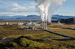
Image: Geothermal power plant

Image credits : Wikipedia

How is electricity produced using geothermal energy?

Geothermal energy is used in power production. The working fluid simply should be able to rotate the blades of turbine. The turbine then transmits the motion to a generator which will produce the electricity.

When the steam with high velocity comes out from the surface of Earth, it rotates the turbine blades. When the turbine blades rotate, the turbine shaft also starts rotating. This shaft is connected to a generator, generator produces electricity there after.

Advantages of geothermal energy

There are numerous advantages of geothermal energy. The list below shows the advantages of geothermal energy-

  • No burning of fossil fuels is required.
  • Abundant in nature so no fear of it being exhausted by excessive use.
  • Very less harmful gases are produced. Only 1/6th of total carbon dioxide is produced in geothermal plants than in conventional gas fueled power plants.
  • The water can be injected back to the Earth making it renewable source of energy.
  • It uses less water than other conventional power plants.

Geothermal energy uses

There are many uses of geothermal energy other than electricity production. The uses are given in the list below-

  • Space heating– We can use geothermal energy to heat up the rooms in our homes. We shall discuss about how to extract the geothermal energy and put it to use in below sections.
  • Hot springs– Hot springs are naturally heated ponds that we can use to bathe and relax. Many health and wellness experts use hot springs as relaxing centers.
  • Electricity generation– Electricity generation is the most common use of geothermal energy. The geothermal energy can be tapped by pumping water on the hot spots present inside the surface of Earth.
  • Cooking– We can use the heat generated by geothermal energy to heat up a space that can be used for cooking.

Geothermal energy sources

The geothermal energy can come out of the surface of Earth in many ways. The different sources of geothermal energy are given in the section below-

  • Volcano– We must have heard about volcano eruptions. Volcanoes have an opening on the top from where the heat is expelled out. The rocks melt when they come in contact with heat, so a thick liquid called as lava is formed which comes out of the volcano.
  • Geysers– Geysers are naturally heated water systems or fountains which occur as a result of groundwater striking the hot spots. The water comes out from the vents called as fumarole.
  • Lava– Lava does not necessarily come out of volcano, it can come out of fumarole as well. The lava are the rocks that were melted when they came in contact with the heat.
  • Hot springs– Hot springs are naturally heated water ponds which can be used for relaxing purposes and bathing. Many fitness experts suggest people to bathe in naturally occurring hot springs.

Geothermal energy examples

The different examples of geothermal energy is given in the list below-

Geothermal heated homes

The geothermal energy finds its application in heating rooms in our homes. In a common geothermal heating systems the coils are places under the surface of earth that extract heat from the ground.

Geothermal power plants

This is the most common application of geothermal energy. Electricity is generated with the help of high pressure steam, turbine and generator. Water is fed in side the surface of Earth which has hot spots. The water after hitting these spots gets heated up and comes out from the surface of Earth as high energy steam.

Hot springs

Hot springs are naturally heated water ponds. The heat comes from naturally from the hot spots present underneath the surface of Earth.

Geothermal geysers

Geothermal geysers are the result of water from water table coming in contact with the hot spots. The water gets converted into steam rapidly and comes out of the surface of Earth due to high pressure formation.

Green houses

To maintain the temperature inside a green house, a network of coils is used. The coils are places under a lake. The water is added with anti freeze materials. The heat extracted from the water is then used to heat the green house. 

Fumarole

When the water from the groundwater table gets heated it comes out from tiny vents. It can be said that the heat leaks out of the surface via these vents. These vents are called as fumarole. Hence a volcano opening or a hot spring opening are examples of fumarole.  

Spas

The hot springs and fumarole as discussed above are used by health and wellness experts for their customers to relax in the warm water. Our muscles can feel relaxed in naturally heated water. Many families make a trip to such places. This has become a tourist attraction at many places.

Also Read:

11+ Osmotic Pressure Example: Detailed Facts

0307 Osmosis 300x170 1

In this article we shall discuss about osmotic pressure example. Osmosis refers to the movement of molecules from an area of higher concentration to lower concentration.

The movement takes place through a semi permeable membrane. This membrane divides the areas of higher concentration and lower concentration. In this article we shall discuss about notable features of osmosis and then discuss about osmotic pressure and its examples.

What is osmosis?

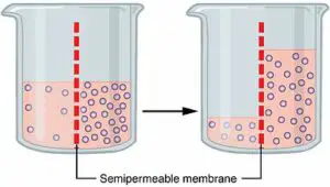
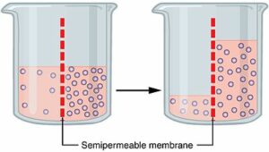
Osmosis refers to transfer of molecules through a semi permeable membrane from an area of higher concentration to an area of lower concentration.

Osmosis can take place in many areas including the cells of our body. The transfer of molecules take place until concentrations at both places become equal. There are many types of osmosis and osmosis solutions, we will discuss about those types in the next section.

osmotic pressure example
Image: Osmosis

Image credits: OpenStax, 0307 OsmosisCC BY 4.0

Types of osmosis solutions

Osmosis solutions are of three types. They are given in the list below-

  1. Isotonic solution- Isotonic solution is that solution in which the concentration of solutes is same both outside and inside the cell.
  2. Hypertonic solution– A hypertonic solution is that solution in which the solute concentration is higher outside than inside.
  3. Hypotonic solution – A hypotonic solution has higher concentration of solute on the inside than outside.

Types of Osmosis

Osmosis is divided into two types. The two types are discussed In the section below-

  1. Endosmosis– When we place a substance in hypotonic solution, the molecules of solvent will move inside the cell making the cell turgid. We can say that it undergoes deplasmolysis. This type of molecule transfer is called as endosmosis.
  2. Exosmosis– When a substance is placed in hypertonic solution, the molecules of solvent will move outside the cell making it flaccid and inflexible. We can say that it undergoes plasmolysis. This type of molecule transfer is called as exosmosis.

What is osmotic pressure?

The molecule transfer through the membrane is spontaneous. That is the molecules will transfer on their own by the virtue of concentration difference between the two areas.

To stop this molecule transfer, a certain of pressure is needed. This pressure is called as osmotic pressure. The osmotic pressure can be determined by concentration of solute. The only way to stop diffusion other than applying osmotic pressure is by making the concentrations at both places equal.

Osmotic pressure formula

In above section, we discussed that to find osmotic pressure, we use the value of solute concentration. The formula to calculate osmotic pressure is given below-

gif

Where,

Pi is the osmotic pressure,

M is the molar concentration of solute

R is the gas constant

T is the temperature at which the molecule transfer is taking place

Osmotic pressure examples

The examples of osmotic pressure are given in the list below-

Transport of nutrients in trees

The transport of nutrients from roots to other branches of tree takes place through osmosis. The concentration of nutrients or water is higher at the bottom or roots. The water is transported to other branches where the concentration is lower.

Perspiration

Perspiration in human beings takes place to keep the body cool when it is exercising or getting exposed to heat. The salty water comes out from the body through tiny pores present in our skin.

Absorption of nutrients from soil

The nutrients are absorbed by the roots through osmosis. The concentration of nutrients is high in the soil. This is why it is recommended to add fertilizers to soil so that the soil remains nutrients rich which will eventually promote growth of plant.

Absorption of water in resin

When we dip resins in water, the resin swells up after a certain period of time. This happens due to the fact that higher amount of sugar is present inside resins. So the water rushes inside the resin.

Oxygen transfer to blood

Oxygen transfer to blood is done by the process of diffusion or osmosis. The cells have a semi permeable membrane through which the transfer of oxygen takes place.

Potato in sugar solution

When we put potato in sugar solution, the size of potato reduces because the concentration of water in potato is higher than in the sugar solution. So the water rushes out of potato making it smaller in size.

Fish absorb water through skin and gills

Fishes absorb water or oxygen from water through their skin and gills. They are semi permeable membranes through which the transfer of water molecules take place.

Red blood cells placed in freshwater

The red blood cells have a semi permeable membrane through which molecule transfer can take place. Red blood cells are rich ions and when places in water these cells get swollen due to the fact that water molecules start entering the red blood cells.

Sugar on strawberries

When we sprinkle sugar on strawberries, the outer membrane of strawberry will act as a semi permeable membrane so the water moves to the outer surface of the strawberry. This happens because of the fact that interior has natural sugar and water in it.

Food preservation

Food preservation is direct application of osmosis. The food becomes rich in sugar, vinegar, preservative oils when the food (for example pickle) is placed inside a jar containing these preservatives.

Absorption of digestive food in large and small intestines

The food when reaches to intestines, it is turned into a thick semi fluid called as chyme. When this thick semi fluid or chyme moves in to small intestine, osmosis takes place.

Contact lens-induced dry eye

When we keep lenses in water they are soft and have moisture in it and when we put it on our eye, it absorbs moisture from the eye via osmosis.

Water purification

The water purifiers use the process of reverse osmosis to filter the water from impurities and unwanted minerals. In the process of reverse osmosis, a pressure greater than the osmotic pressure is applied because of which the separation of solute on one side and solvent on the other side takes place. Here the impurities are the solute and solvent is the water.

Also Read:

9+ Earth Pressure Example: Detailed Facts

220px Earth Pressure In Action

This article discusses about the topic – Earth pressure example. This is a very uncommon fact that Earth exerts a lateral pressure on retaining structures.

We shall see what these retaining structures mean, how does the Earth exert pressure and from where does this pressure originate. We shall also see how to overcome the effect of this pressure and then read more about Earth pressure using its examples. Let us start with the basic definition of Earth pressure.

What is Earth pressure?

The pressure exerted by soil on the surface of retaining structures such as pillars or walls is called as Earth pressure.

The pressure is exerted laterally or horizontally. The magnitude of force exerted depends on the soil stucture and the movement of the retaining system. If the movement is more then the force will simply bring the entire structure down resulting into a massive collapse. Let us see how can we avoid such collapses.

earth pressure example
Image: Retaining wall structure

Image credits : Wikipedia

How to reduce the effect of Lateral Earth pressure?

It is very important to reduce the effect of lateral earth pressure. This can be done by various methods. Some of the methods are discussed in the section given below-

  • By reducing the co efficient of lateral earth pressure
  • Reducing the density of the material to be retained
  • Light weight fills such as egg shells can be used to reduce the density of fill.

Types of Lateral Earth pressure?

There are three types of Lateral Earth Pressure. While building a retaining wall we must keep all of these types in mind.

The three types of lateral earth pressure are given below-

  • Active earth pressure– When soil is allowed to yield sufficiently such that its internal shearing resistance causes its internal shearing resistance  completely mobilized, then the pressure exerted by soil in such condition is called as active earth pressure.
  • Passive earth pressure– When the soil is compressed laterally and causes its internal shearing resistance along a potential failure surface to be mobilized then the pressure exerted by soil under this condition is called as passive Earth pressure.
  • Earth pressure at rest– When there is no lateral strain within the ground mass then the value of pressure exerted by soil in this condition is called as Earth pressure at rest.

Passive earth pressure example

The meaning of passive earth pressure is explained in the above section. Now we shall discuss some examples of passive earth pressure.

The examples are listed below-

Electric pole

When we see electric poles, their length is not that we see, some part of it is fixed underground. This is done so that the pole can have a better grip and does not fall when a slight force is applied on the pole. The part which is underground experiences passive earth pressure on it. The design of poles are made in such a way that they can hold the pressure and do not fail under severe circumstances.

Bridge pillars

Similar to the electric poles, the pillars also have some part fixed inside the ground. This is done to make sure that the pillars get a rigid support. The passive earth pressure is experienced by the portion of the pillar that is underground.

Transmission lines

We all must have seen transmission lines. They appear as human like tall structures that stand upright carrying transmission wires. These structures are fixed underground which provides support to the structure. The passive earth pressure will be acting on the portion lying nside the ground.

Post box

A post box also has some portion of it fixed underground. This is why it stands rigid without getting disturbed. The passive earth pressure acts on that portion of the post box which lies underground. The soil exerts pressure on the retaining portion of the post box.

Dam

Dams are built on a strong foundation. These dams will have its foundation laid underground on which the passive earth pressure acts. To overcome this pressure, several design factors are kept in mind.

Building foundation

Just like dams, foundation of any building is laid underground. The foundation is so rigid that it can support the entire building on it. The passive earth pressure acts on this foundation. The design is made in such a way that it reduces the effect of passive earth pressure.

Flag pole

On various occasions we must have seen flag being hoisted. The flag pole is mounted on a support structure. This support structure has some of its portion underground. This is done so that the support structure will be rigid and not move with the force of winds.

Electric meter

Electric meter is located in almost every street. Ths meter is installed inside a box. This box is a fixed structure that stands upright rigidly. These structure has four legs which are pierced deep in to the soil for gaining rigidity. The passive earth pressure acts on that portion of pillars which lie underground.

Water pump

We must have seen water pumps on street. They are painted mostly in red colour. They are rigid structures which are partially placed underground. The underground portion provides the strength and rigidity to the entire structure. The passive earth pressure acts on the portion which is underground.

Tree

Trees have a complex system of roots that go deep inside the soil to absorb minerals from the it. Some of the trunk portion of the tree gets submersed inside soil on which the passive earth pressure acts. The pressure acts from all directions which in turn ends up providing support to the tree.  

Goal post

Like every other object that we have discussed in this section, goal posts are also fixed in such a way that some of its length is dipped inside the soil. This is done to make the goal post rigid and immobile. The passive earth pressure in all directions which ends up giving strength to the goal post. Goal posts are commonly seen in football, handball etc.

Also, please click to know about 14+ Ocean Pressure Example or read more on 20+ passive Range of motion examples.

Also Read:

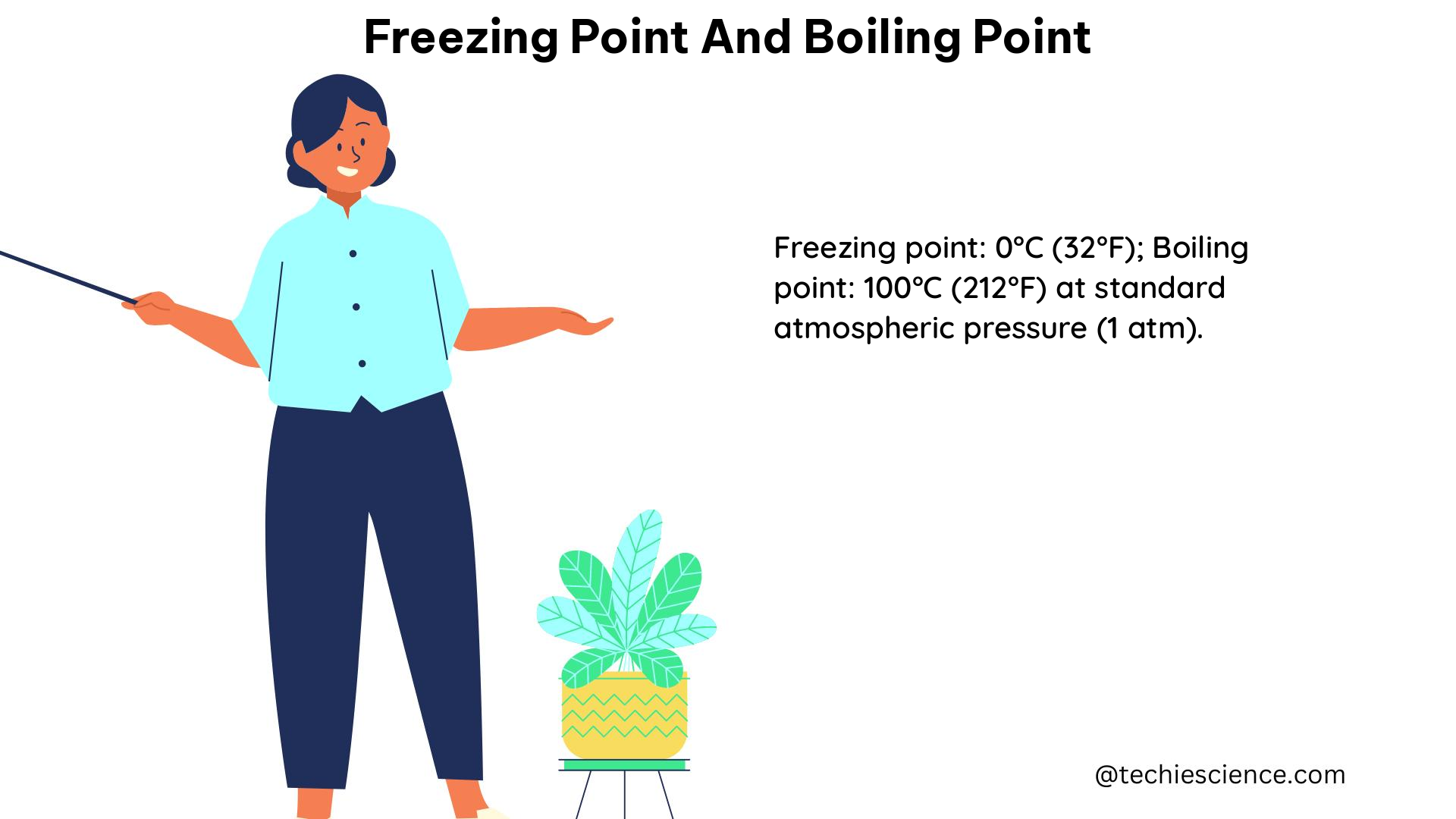
Freezing Point and Boiling Point: A Comprehensive Guide for Physics Students

freezing point and boiling point

The freezing and boiling points of a substance are crucial physical properties that determine the phase transitions between liquid, solid, and gaseous states. These points are essential in various fields, including chemistry, physics, and engineering, as they provide valuable insights into the behavior and characteristics of materials. In this comprehensive guide, we will delve into the technical details, formulas, and practical applications of freezing point and boiling point.

Understanding Freezing Point

The freezing point of a substance is the temperature at which it transitions from a liquid to a solid state. This temperature is typically lower than the melting point, which is the temperature at which a solid transitions to a liquid. The freezing point of a substance is influenced by several factors, including pressure, impurities, and the presence of solutes.

Factors Affecting Freezing Point

  1. Pressure: The freezing point of a substance is affected by changes in pressure. Generally, an increase in pressure leads to a slight decrease in the freezing point, while a decrease in pressure results in a slight increase in the freezing point.

  2. Impurities: The introduction of impurities or solutes into a substance can lower its freezing point. This phenomenon is known as freezing point depression and is a colligative property of solutions.

  3. Solute Concentration: The freezing point depression of a solution is directly proportional to the molality of the solute, which is the number of moles of solute per kilogram of solvent.

Freezing Point Depression Formula

The relationship between the freezing point depression and the molality of the solution is described by the following formula:

[\Delta T_f = k_f \cdot m \cdot i]

Where:
– $\Delta T_f$ is the change in freezing point (in °C)
– $k_f$ is the freezing point depression constant (in °C/m)
– $m$ is the molality of the solution (in mol/kg)
– $i$ is the van’t Hoff factor, which represents the number of particles formed when a solute dissolves in a solvent

Example Calculation

Consider a 0.5 m solution of sodium chloride (NaCl) in water. When NaCl dissolves in water, it dissociates into two ions (Na+ and Cl-), which means that one mole of NaCl produces two moles of ions in solution. Therefore, the van’t Hoff factor for NaCl is 2.

The freezing point depression can be calculated as follows:

[\Delta T_f = k_f \cdot m \cdot i = 1.86^\text{o} \text{C/m} \cdot 0.5 \text{ m} \cdot 2 = 1.86^\text{o} \text{C} \cdot 1 \text{ m} \cdot 2 = 3.72^\text{o} \text{C}]

This means that the freezing point of the NaCl solution is 3.72°C lower than that of pure water.

Understanding Boiling Point

freezing point and boiling point

The boiling point of a substance is the temperature at which it transitions from a liquid to a gaseous state. This temperature is influenced by several factors, including pressure, impurities, and the presence of solutes.

Factors Affecting Boiling Point

  1. Pressure: The boiling point of a substance is directly proportional to the surrounding pressure. An increase in pressure leads to an increase in the boiling point, while a decrease in pressure results in a decrease in the boiling point.

  2. Impurities: The introduction of impurities or solutes into a substance can increase its boiling point. This phenomenon is known as boiling point elevation and is also a colligative property of solutions.

  3. Solute Concentration: The boiling point elevation of a solution is directly proportional to the molality of the solute, which is the number of moles of solute per kilogram of solvent.

Boiling Point Elevation Formula

The relationship between the boiling point elevation and the molality of the solution is described by the following formula:

[\Delta T_b = k_b \cdot m \cdot i]

Where:
– $\Delta T_b$ is the change in boiling point (in °C)
– $k_b$ is the boiling point elevation constant (in °C/m)
– $m$ is the molality of the solution (in mol/kg)
– $i$ is the van’t Hoff factor, which represents the number of particles formed when a solute dissolves in a solvent

Example Calculation

Consider the same 0.5 m solution of sodium chloride (NaCl) in water. Since NaCl dissociates into two ions (Na+ and Cl-) in water, the van’t Hoff factor for NaCl is 2.

The boiling point elevation can be calculated as follows:

[\Delta T_b = k_b \cdot m \cdot i = 0.515^\text{o} \text{C/m} \cdot 0.5 \text{ m} \cdot 2 = 0.515^\text{o} \text{C/m} \cdot 1 \text{ m} \cdot 2 = 1.03^\text{o} \text{C}]

This means that the boiling point of the NaCl solution is 1.03°C higher than that of pure water.

Practical Applications

The understanding of freezing point and boiling point is crucial in various fields, including:

  1. Chemistry: Freezing point depression and boiling point elevation are used to determine the molar mass of unknown substances and to study the properties of solutions.

  2. Physics: These concepts are essential in understanding phase changes, thermodynamics, and the behavior of materials under different temperature and pressure conditions.

  3. Engineering: Freezing point and boiling point data are used in the design and operation of various systems, such as refrigeration, heating, and distillation processes.

  4. Cryogenics: The study of extremely low temperatures, including the freezing point of substances, is crucial in the field of cryogenics, which has applications in areas like superconductivity and space exploration.

  5. Meteorology: The freezing point of water is essential in understanding and predicting weather patterns, such as the formation of ice, snow, and frost.

Conclusion

Freezing point and boiling point are fundamental physical properties that play a crucial role in various scientific and engineering disciplines. By understanding the factors that influence these points, as well as the associated formulas and calculations, physics students can gain a deeper understanding of the behavior of materials and their phase transitions. This knowledge can be applied to solve complex problems, design efficient systems, and advance scientific research.

Reference:

  1. Colligative Properties of Solutions – Introductory Chemistry: https://opentextbc.ca/introductorychemistry/chapter/colligative-properties-of-solutions/
  2. Colligative Properties: Freezing-Point Depression and Molar Mass: http://muhws.freeservers.com/chem/lab19.htm
  3. Colligative Properties- Freezing Point Depression, Boiling Point Elevation, and Osmosis: https://chem.libretexts.org/Bookshelves/General_Chemistry/Map:_A_Molecular_Approach_%28Tro%29/13:_Solutions/13.06:_Colligative_Properties-_Freezing_Point_Depression_Boiling_Point_Elevation_and_Osmosis
  4. Freezing Point Depression and Boiling Point Elevation: https://chem.libretexts.org/Courses/College_of_Marin/CHEM_114:_Introductory_Chemistry/13:_Solutions/13.09:_Freezing_Point_Depression_and_Boiling_Point_Elevation-_Making_Water_Freeze_Colder_and_Boil_Hotter

3+ Lathe Machine Parts: Types And Detailed Explanations About Each Parts

Lathe

This article discusses about lathe machine parts. Before discussing about different moving components used in lathe we shall discuss what is a lathe machine.

Lathe machine is known as the mother of all machines as it can produce a large variety of other machine components and its the basic industrial machine. In this article we shall discuss about different types of lathe machines, applications of lathe machine and related topics.

What is lathe machine?

Lathe can be defined as a machine tool that will rotate a workpiece around its axis rotation to perform various machining operations like cutting, sanding, drilling etc.

Through various machining operations, we can manufacture many products. The lathe machine has many working components which work in harmony to provide the desired results. The lathe has movements possible in x axis and y axis. Let us discuss more about lathe in further sections.

Lathe machine parts and functions

Lathe is an assembly of many components. These components are arranged in such a way that the user can use them simultaneously or one by one as and when needed.

The main parts of lathe are given in the section given below-

Bed

The entire lathe machine rests on the bed. The lathe machine does not have any legs or pillars on which it stands. The bed is made up of cast iron. The bed is bolted to the shop floor such that it holds all the vibrations coming out from the machining process.

Headstock is found at the end of bed. Headstock will provide the power used for rotating the spindle used in lathe machine. The headstock itself is stationary but holds the moving or rotating part of the lathe.

Spindle

Spindle collects the workpiece and provides it motion for machining process. It is simply a rotating shaft which holds the work piece while it rotates.

Leadscrew

Leadscrew is also called as power screw or translation screw. It translates motion form one form to another, it converts the rotary motion to linear motion.

Lathe machine parts diagram

We have discussed about the main parts used in lathe. But addition to these parts there are other small parts too which participate in the working of lathe machine.

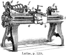
The diagram of lathe machine parts is given below-

Image credits: Wikipedia

  • a- bed
  • b- carriage
  • c- headstock
  • d-back gear
  • e- cone pulley
  • f- faceplate mounted on spindle
  • g- tailstock
  • h- leadscrew

Types of lathe machines

According to the application requirements and the mode of working (automated or manual) the lathe machine is divided into following parts-

  • Automatic lathe machines – Automatic lathe machines as the name suggests are controlled using automatic cutting process. These machines are Numerically controlled or computer numeric control.
  • CNC lathes – CNC is one of the types of automatic lathe machine. It is a machine tool that performs cutting operations automatically by the computer. The operator feeds a code to the machine and the machine will keep performing its operation as per the code.
  • Ornamental– Ornamental lathe is used for ornamental turning. This type of turning involves cutting of work piece that is mounted on lathe.
  • Combination lathe – Combination lathe as the name suggests performs various machining processes such as turning, milling, cutting and drilling. These processes are performed on different lathes in conventional machines.
  • Oil field lathes– These type of lathes have very large spindle bores as well as chucks on headstock. The name oil field lathe comes from the fact that these lathes can be used in oil fields because it can handle long workpieces.
  • Turret lathe – These types of lathe are generally used for repititive production of same designs.

Uses of lathe machine

The uses of lathe machine are given in the section given below-

  • Woodworking – As the name suggests, woodworking refers to the machining of wood work pieces. Wood work pieces are mounted on the lathe and special type of tools are used for woodworking. Many kinds of furniture items are produced using the help of woodworking lathe.
  • Duplicating – We can copy or duplicate a shape using a special type of lathe known as copy lathe. This type of lathe is used for replicating objects.
  • Pattern making– Pattern making is also a type of duplicating process. Patterns are made for making moulds that are used in casting process.
  • Metal working – Metal working is simple metal machining process in which the metal surfaces are chipped off to make the desired shapes.
  • Metal spinning– In metal spinning a disc of metal is rotated around a center and a tool that is kept stationary cuts the metal. This is also called as metal turning.
  • Glass working– Glass working as the name suggests is the technique in which various methods are used to cut and make designs from glass.
  • Ornamental turning– In ornamental turning, there is facility to cut the workpiece mounted on the lathe.
  • Reducing– In reducing process, the radius of the workpiece is reduced from the original dimension to the desired dimension. In the operation the workpiece and the cutting tool are kept perpendicular to each other.
  • Watchmaking– Watchmaking is a process of making watches. In watchmaking lathes, the tools are designed in such a way that we can manufacture watch parts on it.

Accessories used on lathes

Accessories used in lathes improve the performance of lathe. These accessories make it easy and convenient for the althe operator to operate the machine.

The accessories used in lathe machine are given in the section below-

  • Faceplate– Faceplate is a holding accessory in a lathe. The faceplate can be used to hold both wood and metal workpieces.
  • Four jaw/three jaw chuck- The chucks are used for clamping the work pieces. Three jaw chucks are commonly used for circular workpiece whereas uneven workpieces can be worked upon four jaw chucks. In four jaw chucks, each jaw needs to be fit manually whereas in three jaw chuck all the three jaws move together.
  • Collet– Collet is also used for holding circular objects by making a collar around it. This collar exerts a strong clamping force on the object.
  • Dead center- A dead center is used to support the workpiece at either the fixed part or rotating part in the machine.

Efficiency Of Internal Combustion Engine: What, How, Different Types and Facts

Carnot cycle pV diagram.svg

In this article we shall discuss about the topic- Efficiency of internal combustion engine. Internal combustion engines are commonly used in locomotives to run them.

The internal combustion engines or IC engines use the thermal energy from burnt fuel and gets it converted to mechanical energy. The speed of locomotives depend on how fast the combustion cycle is repeating itself inside the engine. In this article we shall study about internal combustion engines in detail.

What is internal combustion engine?

Internal combustion engines are heat engines inside which the fuel is combusted with the help of an oxidizer. The resulting thermal energy is converted to mechanical energy by pushing the piston to the bottom most part of the cylinder

The piston moves back and forth performing a reciprocating motion. The reciprocating motion of piston is directed to the crankshaft. The crankshaft starts rotating as a result of which the wheels also rotating. We shall study more about internal combustion engines in detail in further sections of this article.

How does an internal combustion engine work?

Internal engines work by converting the thermal energy, produced after combusting fuel in the presence of an oxidizer, to mechanical energy. When the piston is at top dead center, fuel is burnt as a result of which some amount of thermal energy is released.

This energy pushes the piston to the bottom dead center. The piston moves to the top dead center again due to inertia, this time the exhaust gases are expelled out from the exit valve. The piston is connected to a crank through connecting rod which converts the reciprocating motion of piston to rotary motion.

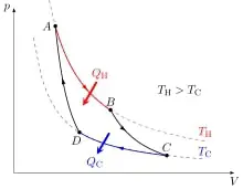
Carnot cycle pV diagram.svg
Image: Carnot Cycle

Image credits: Cristian QuinzacaraCarnot cycle pV diagramCC BY-SA 4.0

What is the efficiency of internal combustion engine?

We now know the working of intrernal combustion engine works. We know that internal engine can produce its own work.

Now we shall discuss about the efficiency of an internal efficiency. It is defined as the amount of work that the engine has produced to the heat input to the engine.  

Mathematically, efficiency is given as-

Input

Heat efficiency of internal combustion engine

Heat efficiency of internal combustion engine is the ratio of useful heat to the total heat input given to the system.

The heat source provides the heat to the heat engine and a heat sink absorb all the waste heat from the engine. The useful heat is used as the work output from the engine. The heat efficiency of an internal combustion engine is given in the section given below-

Input

Volumetric efficiency of an internal combustion engine

The volume of the cylinder is called as the swept volume which is the maximum volume of air fuel mixture that can be taken in.

Volumetric efficiency is the ratio of total air fuel mixture taken inside the cylinder to the total volume of the cylinder or the swept volume. Mathematically, the volumetric efficiency of an internal combustion engine is given in the section below-

V %7Bswept%7D

Overall efficiency of internal combustion engine

Overall efficiency of any heat engine takes into account all types of efficiencies namely, thermal efficiency, mechanical efficiency, volumetric efficiency etc.

Mathematically, the overall efficiency of internal combustion engine is –

Input

What is mechanical efficiency of an internal combustion engine?

Mechanical efficiency is the efficiency with which the mechanical components inside the internal combustion engine work.

The mechanical components include piston, valves, piston pin cylinder etc. The engine works when these mechanical components work in harmony with each other. Mechanical efficiency is a ratio between two things, they are work output and work input.

What is the maximum efficiency of internal combustion engine?

Different internal combustion engines have different efficiencies. The efficiencies depend on the mechanical efficiency, type of fuel used, type of engine etc.

The most efficient internal combustion engines have an efficiency of 50% but the engines that are allowed on road have efficiencies between 20 to 30 percent. Combustion engines are not as efficient as we though them to be as the energy conversion rate is very low.

How to calculate the efficiency of internal combustion engine?

In above sections we saw the formula of calculating efficiency of internal combustion engine. In those sections we did not discuss about how to find the quantities used in that formula.

The work done is defined as the net useful heat taken from the heat input. So the net work can be found simply by subtracting Heat input and heat output. The difference between the two will give us the net work output. When we divide the work output by heat input swe get the value of efficiency. We have already discussed the formula in above sections.

Efficiency of internal combustion engine vs electric motor

We have already discussed about the maximum efficiencies of internal combustion engines. The electric motor vehicles do not burn fuel to run.

Electric motors on the other hand have higher efficiency than combustion engines. The energy conversion rate of electric motor is 85 % . So we can say that the electric motors have an efficiency of around 80%-85% whereas the maximum efficiency of an internal combustion engine can go nearly up to 50%.

Efficiency of internal combustion engine vs gas turbine

Gas turbines are mechanical devices that convert heat energy from steam to mechanical energy. The mechanical energy will be converted then to electrical energy which is done with the help of a generator.

Gas turbines have an efficiency of around 35-40%. That is more than most of the internal combustion engines. But we do not use gas turbines in locomotives because of the size. Internal combustion engines are compact in size whereas the gas turbines are huge and are used in applications with high speeds.

How to increase efficiency of internal combustion engine?

To increase the efficiency of internal combustion engines we use the following methods-

  • Lower heat rejection
  • High compression ratio
  • Using a lean fuel mixture
  • Running the engine at optimum conditions

Why are gas turbines not used in vehicles if they have higher efficiency?

The efficiency of gas turbines may be higher. We have discussed the numbers in the above sections already. But the reason why they are not used in vehicles is the size of a turbine.

The size of a gas turbine is very large. This is why turbines are used in aeroplanes and not in vehicles. The gas turbines are used where the application deals with high speed. Internal combustion engines are compact in size hence they are used in vehicles and gas turbines are not.

Boiling Point and Dipole Moment: A Comprehensive Guide for Physics Students

boiling point and dipole moment

Boiling point and dipole moment are two fundamental properties in physics and chemistry that play a crucial role in understanding the behavior of substances and their interactions. This comprehensive guide will delve into the intricacies of these properties, providing you with a deep understanding of their measurement, factors affecting them, and their practical applications.

Boiling Point: Mastering the Phase Transition

Boiling point is the temperature at which the vapor pressure of a liquid equals the pressure surrounding the liquid, and bubbles of vapor form inside the liquid. This phase transition from liquid to gas is a crucial concept in thermodynamics and has numerous applications in various fields.

Factors Affecting Boiling Point

The boiling point of a substance can be influenced by several factors, including:

  1. Intermolecular Forces: The strength of intermolecular forces, such as van der Waals forces, hydrogen bonding, and dipole-dipole interactions, can significantly affect the boiling point. Substances with stronger intermolecular forces generally have higher boiling points.

  2. Molecular Mass: Larger molecules typically have higher boiling points due to their increased surface area and stronger intermolecular interactions.

  3. Atmospheric Pressure: The boiling point of a substance is inversely proportional to the surrounding atmospheric pressure. As the pressure decreases, the boiling point also decreases, as demonstrated by the Clausius-Clapeyron equation.

  4. Solute Concentration: The presence of solutes in a solution can increase the boiling point of the solvent, a phenomenon known as boiling point elevation. This property is used in various applications, such as determining the molar mass of unknown compounds.

Measuring Boiling Point

The boiling point of a substance can be measured using a simple apparatus consisting of a thermometer and a heat source. The sample is heated, and the temperature at which the first bubble of vapor forms is recorded as the boiling point. More advanced techniques, such as using a Cottrell boiling point apparatus or a Siwoloboff boiling point apparatus, can provide more accurate and precise measurements.

Boiling Point Examples and Numerical Problems

  1. Example: The normal boiling point of water is 100°C at 1 atm pressure. Calculate the boiling point of water at 2 atm pressure.

Solution: Using the Clausius-Clapeyron equation, we can calculate the new boiling point:

ln(P2/P1) = (ΔHvap/R) * (1/T1 – 1/T2)
where:
P1 = 1 atm
P2 = 2 atm
T1 = 373.15 K (100°C)
ΔHvap = 40.66 kJ/mol (latent heat of vaporization of water)
R = 8.314 J/mol·K

Solving for T2, we get:
T2 = 383.94 K (110.79°C)

  1. Numerical Problem: A solution containing 5.0 g of a non-volatile solute in 100 g of water has a boiling point of 100.52°C. Calculate the molar mass of the solute.

Given:
– Mass of solute = 5.0 g
– Mass of solvent (water) = 100 g
– Boiling point of the solution = 100.52°C
– Boiling point of pure water = 100°C
– Boiling point elevation constant for water = 0.512°C/m

Solution:
Using the formula for boiling point elevation:
ΔTb = Kb * m
where:
ΔTb = Boiling point elevation
Kb = Boiling point elevation constant
m = Molality of the solution

Rearranging the formula, we can find the molality:
m = ΔTb / Kb
m = (100.52°C – 100°C) / 0.512°C/m
m = 1.0 m

Now, we can calculate the molar mass of the solute using the definition of molality:
m = (mass of solute) / (mass of solvent * molar mass of solute)
1.0 m = (5.0 g) / (100 g * molar mass of solute)
Molar mass of solute = 100 g / 5.0 g = 20 g/mol

Dipole Moment: Quantifying Molecular Polarity

boiling point and dipole moment

Dipole moment is a measure of the separation of positive and negative charges within a molecule, which determines the polarity of the molecule. Understanding dipole moments is crucial in various fields, including chemistry, materials science, and biology.

Measuring Dipole Moment

Dipole moments can be measured using several experimental techniques, including:

  1. Balance Method: In this method, a polar molecule is suspended between two electrodes, and its deflection in an electric field is observed. The degree of deflection is proportional to the dipole moment of the molecule.

  2. Dielectric Constant Measurement: By measuring the dielectric constant of a substance, the dipole moment can be inferred. Substances with higher dielectric constants generally have stronger dipole moments.

  3. Spectroscopic Techniques: Techniques such as NMR and IR spectroscopy can provide information about the orientation and strength of dipole moments in a molecule.

Factors Affecting Dipole Moment

The dipole moment of a molecule can be influenced by several factors, including:

  1. Electronegativity Difference: The difference in electronegativity between the atoms in a molecule determines the degree of charge separation and, consequently, the dipole moment.

  2. Molecular Geometry: The spatial arrangement of atoms in a molecule, as described by the VSEPR theory, can affect the distribution of charges and the resulting dipole moment.

  3. Hybridization: The type of hybridization (sp, sp², sp³) can influence the dipole moment by affecting the bond angles and the distribution of electrons.

  4. Resonance: The presence of resonance structures in a molecule can alter the charge distribution and, therefore, the dipole moment.

Dipole Moment Examples and Numerical Problems

  1. Example: Calculate the dipole moment of the water molecule (H₂O) given that the bond angle is 104.5° and the bond length is 0.957 Å. The electronegativity difference between oxygen and hydrogen is 1.4.

Solution:
Using the formula for dipole moment:
μ = q * r * cos(θ/2)
where:
q = Charge separation (electronegativity difference)
r = Bond length
θ = Bond angle

Substituting the values:
q = 1.4 (electronegativity difference between O and H)
r = 0.957 Å
θ = 104.5°

μ = 1.4 * 0.957 Å * cos(104.5°/2)
μ = 1.85 D (Debye)

  1. Numerical Problem: The dipole moment of a certain molecule is measured to be 2.1 D. Calculate the charge separation within the molecule if the bond length is 1.2 Å.

Given:
– Dipole moment (μ) = 2.1 D
– Bond length (r) = 1.2 Å

Solution:
Using the formula for dipole moment:
μ = q * r * cos(θ/2)
Rearranging the formula to solve for the charge separation (q):
q = μ / (r * cos(θ/2))

Assuming the bond angle (θ) is 180° (a linear molecule),
cos(θ/2) = cos(90°) = 0

Substituting the values:
q = 2.1 D / (1.2 Å * 0)
q = ∞ (Infinite)

This result indicates that the formula is not applicable for a linear molecule, as the cos(θ/2) term becomes zero, leading to an infinite charge separation. For linear molecules, the dipole moment is directly proportional to the charge separation.

These examples and numerical problems demonstrate the application of the concepts of boiling point and dipole moment in various scenarios, helping you develop a deeper understanding of these important properties.

Computational Methods for Boiling Point and Dipole Moment

In addition to experimental techniques, computational methods can also be used to estimate boiling points and dipole moments. These methods, based on quantum mechanical calculations, can provide valuable insights into the behavior of molecules and their interactions.

Quantum Mechanical Calculations

Quantum mechanical calculations, such as those based on the Schrödinger equation, can be used to determine the electronic structure of molecules and, consequently, their dipole moments. These calculations take into account the distribution of electrons within the molecule and the resulting charge separation.

For boiling point estimation, computational methods can be used to predict the vapor pressure of a substance, which is directly related to the boiling point through the Clausius-Clapeyron equation.

Molecular Dynamics Simulations

Molecular dynamics simulations can be employed to study the behavior of molecules, including their boiling point and dipole moment. These simulations model the interactions between atoms and molecules, allowing researchers to predict the properties of substances under various conditions.

Applications in Drug Discovery and Material Science

The ability to accurately predict boiling points and dipole moments using computational methods is particularly valuable in fields such as drug discovery and material science. In drug discovery, understanding the intermolecular interactions between drug candidates and their targets is crucial for designing effective and selective drugs. Similarly, in material science, the design of new materials with desired properties often relies on the accurate prediction of boiling points and dipole moments.

Conclusion

Boiling point and dipole moment are fundamental properties in physics and chemistry that play a crucial role in understanding the behavior of substances and their interactions. This comprehensive guide has provided you with a deep understanding of these properties, including the factors that affect them, the experimental techniques used to measure them, and the computational methods employed to estimate them.

By mastering the concepts of boiling point and dipole moment, you will be better equipped to tackle a wide range of problems in various fields, from thermodynamics and materials science to drug discovery and beyond. Remember to continue exploring and applying these principles to deepen your understanding and unlock new insights in the world of physics and chemistry.

Reference:

  1. Atkins, P., & de Paula, J. (2014). Atkins’ Physical Chemistry (10th ed.). Oxford University Press.
  2. Levine, I. N. (2009). Physical Chemistry (6th ed.). McGraw-Hill.
  3. Silbey, R. J., Alberty, R. A., & Bawendi, M. G. (2005). Physical Chemistry (4th ed.). Wiley.
  4. Engel, T., & Reid, P. (2013). Physical Chemistry (3rd ed.). Pearson.
  5. Reger, D. L., Goode, S. R., & Ball, D. W. (2010). Chemistry: Principles and Practice (3rd ed.). Cengage Learning.

Comprehensive Guide: How to Find the Boiling Point of a Compound

how to find boiling point of a compound

Summary

Determining the boiling point of a compound is a crucial step in understanding its physical properties and behavior. This comprehensive guide will provide you with a detailed, hands-on approach to finding the boiling point of a compound using the Thiele tube method. We will delve into the theoretical explanation, advanced practical details, and numerical examples to help you master this essential technique.

Understanding the Boiling Point

how to find boiling point of a compound

The boiling point of a compound is the temperature at which its vapor pressure equals the surrounding atmospheric pressure. At this point, the compound undergoes a phase transition from a liquid to a gas. The boiling point is a fundamental property that influences various chemical and physical processes, such as distillation, evaporation, and phase equilibria.

Theoretical Explanation

The relationship between the boiling point, vapor pressure, and other thermodynamic variables can be described by the Clausius-Clapeyron equation:

ln(P2/P1) = -ΔHvap/R * (1/T2 - 1/T1)

Where:
P1 and P2 are the vapor pressures at temperatures T1 and T2, respectively.
ΔHvap is the molar enthalpy of vaporization (heat of vaporization) of the compound.
R is the universal gas constant.

By rearranging this equation, we can calculate the boiling point of a compound given the necessary thermodynamic data.

The Thiele Tube Method

The Thiele tube method is a widely used technique for determining the boiling point of a compound due to its simplicity and accuracy. Here’s a step-by-step guide on how to use this method:

  1. Prepare the Sample: Fill a small, narrow-necked glass tube (Thiele tube) about half-full with the compound you want to measure the boiling point for.

  2. Insert the Capillary Tube: Carefully insert a closed-end capillary tube into the sample-filled Thiele tube, with the closed end facing upwards.

  3. Attach the Thermometer: Secure the Thiele tube to a thermometer using a small rubber band or clamp.

  4. Heat the Tube: Gently and continuously heat the arm of the Thiele tube using a burner or hot plate.

  5. Observe the Bubbles: Continue heating until a vigorous stream of bubbles emerges from the capillary tube.

  6. Cool the Tube: Remove the heat source and allow the compound to cool.

  7. Determine the Boiling Point: The boiling point is the temperature at which the compound just begins to enter the capillary tube.

This method typically requires less than 0.5 mL of the sample and provides accurate results.

Example: Determining the Boiling Point of Ethanol

Let’s say we want to find the boiling point of ethanol using the Thiele tube method. We follow the steps outlined above and observe that the boiling point of ethanol is 76°C (765 mm Hg).

Numerical Problem

Given the following data, calculate the boiling point of a compound:

  • P1 = 1 atm
  • T1 = 25°C
  • P2 = 2 atm
  • ΔHvap = 40.67 kJ/mol

Using the Clausius-Clapeyron equation, we can solve for the boiling point (T2):

ln(2) = -40670/8.314 * (1/T2 - 1/298.15)

Solving for T2, we get:
T2 = 351.45 K or 78.3°C

Additional Considerations

  • The Thiele tube method is suitable for compounds with boiling points ranging from 50°C to 300°C.
  • For compounds with very low or high boiling points, other methods, such as distillation or reflux, may be more appropriate.
  • Ensure that the Thiele tube is clean and dry before use to avoid contamination.
  • Carefully control the heating rate to prevent superheating or bumping, which can affect the accuracy of the boiling point measurement.
  • Consider the purity of the compound, as impurities can influence the boiling point.
  • Repeat the measurement several times to ensure consistency and accuracy.

Conclusion

Determining the boiling point of a compound is a fundamental task in chemistry and physics. The Thiele tube method provides a simple, efficient, and accurate way to measure this important property. By understanding the theoretical principles, following the step-by-step practical guidelines, and applying numerical examples, you can become proficient in finding the boiling point of a wide range of compounds.

References

  1. Chem LibreTexts, “Boiling Point Determination,” [Online]. Available: https://chem.libretexts.org/Bookshelves/Organic_Chemistry/Organic_Chemistry_Lab_Techniques_(Nichols)/06%3A_Miscellaneous_Techniques/6.02%3A_Boiling_Point/6.2B%3A_Step-by-Step_Procedures_for_Boiling_Point_Determination.
  2. Socratic, “How do you calculate boiling point?,” [Online]. Available: https://socratic.org/questions/how-do-you-calculate-boiling-point.
  3. SlideShare, “Determination of Boiling Point,” [Online]. Available: https://www.slideshare.net/slideshow/determination-of-boiling-point/253872205.