13 Thermal Insulation Examples: Detailed Insights

blue 5457731 960 720 300x169 1

In this article “Thermal insulation examples” will be discuss with its related several facts. Thermal insulation examples are not suitable for transferring the heat from one circumstance to another circumstance.

13+ Thermal Insulation Examples with several facts are listed below,

Thermal insulation examples:-

In our surroundings lots of insulators are present in solid state. The examples solid state insulators are,

Glass:-

  1. The solid insulator example is glass. From the definition of thermal insulation we can get an idea that the heat cannot from one space to another space. The electrons which are present in the glass not able to carry heat just because of the electrons are participating chemical bonds for this reason the electrons are could not get free time to conducting heat and heat cannot flow from circumference to another circumference.
  2. Ordinary glass is appropriate example of solid thermal insulator just one problem with the glass is it is brittle.
  3. Dielectric constant in nature.
  4. Glass has very less temperature coefficient.
Thermal insulation examples
Image – Blue Crystal Cube made with glass;
Image Credit – pixabay

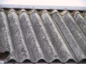
Asbestos:-

  1. The solid insulator example is Asbestos. The electrons which are present in the asbestos not able to carry heat just because of the electrons are participating chemical bonds for this reason the electrons are could not get free time to conducting heat and heat cannot flow from circumference to another circumference.
  2. Not brittle
  3. Resistance to heat
  4. Resistance to wear
  5. Flexible
  6. High strength
800px Wellasbestdach 233 3354 IMG
Image – Asbestos;
Image Credit – Wikimedia Commons

Bakelite:-

  1. Bakelite is heat proof.
  2. Bakelite material is acid proof.
  3. Bakelite is a material which is very strong in mechanically.
  4. Bakelite is a polymer which made with monomers of formaldehyde and phenol.
  5. Another solid insulator example is Bakelite. The electrons which are present in the Bakelite not able to carry heat just because of the electrons are participating chemical bonds for this reason the electrons are could not get free time to conducting heat and heat cannot flow from circumference to another circumference.
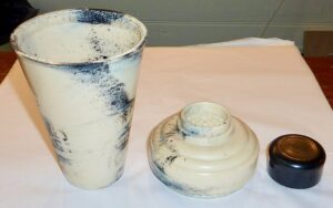
1024px Bakelite Cocktail Shaker
Image – Bakelite Cocktail Shaker; Image Credit – Wikimedia Commons

Mica:-

  1. Highly reflective.
  2. Flexible
  3. Another example of thermal insulator is Mica. The electrons which are present in the mica not able to carry heat just because of the electrons are participating chemical bonds for this reason the electrons are could not get free time to conducting heat and heat cannot flow from circumference to another circumference.
  4. Low thermal conductivity.
  5. Mica affected by oil.
  6. Mica is rigid.
  7. In high temperature mechanically the mica became week.
  8. High dielectric strength is about 30 kV/mm.

Rubber:-

  1. Rubber is the insulator of thermal example. The electrons which are present in the rubber not able to carry heat just because of the electrons are participating chemical bonds for this reason the electrons are could not get free time to conducting heat and heat cannot flow from circumference to another circumference.
  2. Rubber has tensile strength.
  3. Tear resistance
  4. Elongation
  5. Abrasion resistance
  6. Specific gravity
  7. Tensile modulus
  8. Hardness

Paper:-

  1. The electrical property of the paper is adequately good.
  2. Paper is made from wood pulp after that manila fibers are beaten and finally rolled into sheets.
  3. Another solid insulator example is Paper. The electrons which are present in the paper not able to carry heat just because of the electrons are participating chemical bonds for this reason the electrons are could not get free time to conducting heat and heat cannot flow from circumference to another circumference.
  4. Papers have dielectric strength near about 4 to 10 kV/mm.
  5. Hygroscopic
  6. The application of paper is wallpaper, filter paper, writing, toilet tissue, security paper and laminated worktops.

Silk or cotton:-

  1. Elasticity
  2. Light weight
  3. Easy to use
  4. Initial cost is low
  5. Available
  6. Silk or cottons have dielectric strength
  7. Thermal insulator another example is Silk or cotton. The electrons which are present in the silk or cottons not able to carry heat just because of the electrons are participating chemical bonds for this reason the electrons are could not get free time to conducting heat and heat cannot flow from circumference to another circumference.
  8. Silk or cottons can be used in various ways such as cooking oils, making of clothes, towels, sheets, currency paper, animal feed biofuels and many more.
Rajshahi silk fabric Sopura Silk Mills Ltd 01
Image – Rajshahi silk fabric,
Image Credit – Wikimedia Commons

Ceramics:-

  1. Ceramics materials are brittle type
  2. Hard
  3. Nonmagnetic
  4. Another solid insulator example is Ceramics. The electrons which are present in the ceramics not able to carry heat just because of the electrons are participating chemical bonds for this reason the electrons are could not get free time to conducting heat and heat cannot flow from circumference to another circumference.
  5. Oxidation resistant
  6. Prone to thermal shock
  7. Ceramics are both thermal insulator and electrical insulator
  8. Ceramics uses in cutting tools, in space industry.
  9. Ceramics works as both thermal insulator and electrical insulator.

Dry air:-

  1. Dry air is thermal insulator. The electrons which are present in the Bakelite not able to carry heat just because of the electrons are participating chemical bonds for this reason the electrons are could not get free time to conducting heat and heat cannot flow from circumference to another circumference.
  2. Dry air not easily affected by heat
  3. Exerts pressure
  4. Can be compressed
  5. Affected by altitude
  6. Economical
  7. Eco friendly
  8. Light weight
  9. Easy to use
  10. Initial cost is low
  11. Available

Wood:-

  1. Wood has good amount of strength.
  2. Wood is another example for thermal insulator. The electrons which are present in the wood not able to carry heat just because of the electrons are participating chemical bonds for this reason the electrons are could not get free time to conducting heat and heat cannot flow from circumference to another circumference.
  3. Wood has both two characteristics such as tension and compression
  4. Rigid
  5. Relatively light weight
  6. Easy to install
  7. Economical
  8. Eco friendly
  9. Any type of size and shape can be given to wood.
  10. Wood can be used in various fields such as packing, weapons, tools, paper, artwork, constructions and many more.

Diamond:-

  1. Diamond is not brittle type
  2. Another example is Diamond of thermal insulator. The electrons which are present in the diamond not able to carry heat just because of the electrons are participating chemical bonds for this reason the electrons are could not get free time to conducting heat and heat cannot flow from circumference to another circumference.
  3. Diamonds have thermal conductivity
  4. Combustibility
  5. Compressive strength
  6. Tear resistance

Plastic:-

  1. Plastic is water resistant
  2. Plastic is shock resistant
  3. Another example is plastic of thermal insulator, the electrons which are present in the plastic not able to carry heat just because of the electrons are participating chemical bonds for this reason the electrons are could not get free time to conducting heat and heat cannot flow from circumference to another circumference.
  4. Light weight
  5. Easy to install
  6. Maintenance cost in very minimal
  7. Easy to give size and shape
  8. Combustibility
  9. Compressive strength
  10. Recyclable
MUOVI Kaimu
Image – Containers made with plastics; Image Credit – Wikimedia Commons

Styrofoam:-

  1. Styrofoam is another example of thermal insulator. Thermal insulator material means from where heat cannot flow one area to another area among them Styrofoam is. The electrons of the Styrofoam could not carry electrons just because of the electrons which are present in the Styrofoam they are engage to make chemical bonds to each other for this reasons the electrons are not free to take part in the conduction of heat, for this reason heat could not flow through Styrofoam material.

Vapor Compression Refrigeration Cycle: What, Diagram, Efficiency, Working, Steps

vapor compression refrigeration cycle 0

In this article the “Vapor compression refrigeration cycle” topic and vapor compression refrigeration cycle related facts are going to summarize to briefly that a clear concept can we get from it effortlessly.

In vapor compression refrigeration cycle a refrigerant which is stays in fluid is used within a system which stays in as closed and proposed to going in four methods such as compression, then cooling with condensation, after that that expansion and lastly heating with evaporation.

What is vapor compression refrigeration cycle?

In the system of air conditioning the vapor compression refrigeration cycle is commonly used. The fluid which is works as medium in the vapor compression refrigeration cycle is states in vapor state.

Vapor compression refrigeration cycle can be explain in this way lowering the inside temperature of a closed system than the normal temperature and helps to reject the excess amount of heat from the area of the closed system and after doing this process finally transfer the excess amount of heat in environment.

Vapor compression refrigeration cycle
Image – A simple stylized diagram of a heat pumps’s Vapor compression refrigeration cycle
1. Condenser; 2. Expansion valve; 3. Evaporator; 4. Compressor ;
Image Credit – Wikipedia

The compression refrigeration cycle of vapor is used in many purposes like, for domestic purposes, commercial purposes, industrial services and automobile sectors.

In vapor compression cycle the refrigerants which are used commonly they are, NH­_3, R – 12, and R- 11. In the vapor compression cycle of a refrigeration system which components are used they are listed below,

  • Refrigerant compressor
  • Liquid compressor
  • Liquid receiver
  • Evaporator valve

Expansion valve These Evaporator valve and Expansion valve both are called as refrigerant control valve.

Vapor compression refrigeration cycle diagram:

The Vapor compression cycle contain liquid refrigerant which act as a medium of the vapor compression refrigeration cycle. The refrigerant changes state of phase during the process for two times.

A simple type of vapor compression refrigeration cycle diagram if we observe then can found main four components.

They are components are,

Compressor:-

The refrigerant when it is vapour state that time it carry lower temperature and lower pressure than the regular one and enters to the compressor of the vapor compression refrigeration cycle from the evaporator of the system. After enter to the evaporator the vapour became carry higher temperature as well as higher pressure. The refrigerant vapor of the system which carries higher temperature and higher pressure is entering to the condenser with the help of discharge valve.

Condenser:-

In the condenser when the refrigerant vapors of the system which carries higher temperature and higher pressure is enter that time the vapor of the refrigerant became condensed and cooled for the coils are present in the pipe inside the air conditioning system.

When the refrigerant is go through the condenser that time latent heat is emitted in the surrounding of the condensing medium which consider as water or air.

Read more about Hydrocyclone Separator

Receiver:-

The liquid refrigerant which is in condensed state of phase is stored in a container from the condenser. The container where liquid refrigerant is stores is known as receiver. After go through the condenser liquid refrigerant is comes to the evaporator by the evaporator valve.

Expansion valve:-

Another name for the expansion valve is throttle valve. The function of expansion valve is to give permission to liquid refrigerant go through with high temperature and high pressure where the liquid refrigerant could reduce its pressure and temperature.

Evaporator:-

In the evaporator of any cooling system contain pipes or coils where the liquid refrigerant has low temperature and low pressure. In evaporator liquid refrigerant is evaporated and transfer into vapor refrigerant where the temperature and pressure is both are stays in low.

In the beginning of the process the liquid refrigerant change its state of phase liquid to vapor and after that the liquid refrigerant change state of phase from vapor state to liquid.

Vapor compression refrigeration cycle T-S and P-V diagram:

For any cooling system the cycle process of vapor compression can be figure out with the help of Pressure – Volume diagram and Temperature –Specific entropy diagram.

Pressure – Volume diagram

512px Refrigeration PV diagram.svg
Image – Pressure – Volume diagram; Image Credit – Wikipedia

Temperature –Specific entropy diagram

RefrigerationTS
Image – Temperature –Specific entropy diagram;
Image Credit – Wikipedia

If we observe the Pressure – Volume diagram and Temperature –Specific entropy diagram then can figure out refrigerant vapor is entr to the compressor in dry saturation situation. After that the saturated and dry refrigerant vapor is enter to the compressor of the refrigeration system at the point 1 where the vapor refrigeration is compress in isentropically process. Now the vapor refrigerant is go from 1 point to 2 point at this particular time pressure is increases from pressure of evaporator to pressure of condenser.

Now at the point 2 saturated refrigerant vapor is enter to the condenser. In condenser heat is emitted at the fixed pressure. For emission of heat normally temperature of the system is decreases and at the same time change of phase is happened. Latent heat is rejected and reaches to liquid refrigerant at saturation temperature at the point of 3.

Then the liquid refrigerant is passes by the expansion valve. In this situation liquid refrigerant decreases its pressure and throttle upbringing the enthalpy constant.

How vapour compression refrigeration system works?

The Vapor compression cycle is a method which is most commonly used in various fields because its cost of charge is very low and the construction of the vapor compression cycle is quite easy to establish.

The cycle process of vapor compression in refrigeration system is working based on reverse Rankine cycle. The Vapor compression cycle process is proceeding in four steps. They are listed below,

Refrigeration
Image – The cycle process of vapor compression in refrigeration system; Image Credit – Wikipedia

In this below section the four steps are discusses,

Compression (Reversible adiabatic compression):

 The refrigerant of vapor compression cycle at low temperature and pressure stretched from evaporator to compressor where the refrigerant is compressed isentropically. The pressure is rises from p1 to p2 and temperature is rises from T1 to T 2.  The total workdone per kg of refrigerant happened during isentropic compression can be express as,

w = h2 – h1

Where,

h1 = Amount of enthalpy of vapor compression cycle in temperature T1, at the step of suction of compressor

h2  = Amount of enthalpy of vapor compression cycle in temperature T2, at the step of discharge of compressor.

Condensation (Constant pressure heat rejection):

The refrigerant of vapor compression cycle is passes through from compressor to condenser at high temperature and pressure. At constant pressure and temperature the refrigerant is completely condensed. The refrigerant changes its state from vapor to liquid.

Throttling (Reversible adiabatic expansion):

At high temperature and high pressure the refrigerant of vapor compression cycle is expanded through the process of throttling. That time the expansion valve is stays in low temperature and pressure. A little amount of liquid refrigerant is evaporating by the help of expansion valve and a huge amount of liquid refrigerant is vaporised by the help of evaporator.

Evaporation (Constant pressure heat addition):

The refrigerant mixture of vapor and liquid is completely evaporated and changed itself into vapor refrigerant. During this evaporation process the refrigerant is absorb latent heat which state is cool. The amount of latent heat absorption by the refrigerant in vapor cycle is known as Refrigerating effect.

Performance of vapour compression cycle in the refrigeration system:

The vapour compression cycle in the refrigeration system is working at evaporator in the law of Steady Flow Energy Equation,

h4 + Qe = h1 + 0

Qe = h1 – h4

The vapour compression cycle in the refrigeration system is working at condenser in the law of Steady Flow Energy Equation,

h2 + Qc = h3 + 0

Qc = h3 – h2

The vapour compression cycle in the refrigeration system is working at expansion valve in the law of Steady Flow Energy Equation,

h3 + Q = h4 + W

We know, value of Q and W is 0

So, we can write,

h3 = h4

Performance of vapour compression cycle in the refrigeration system is,

gif

Vapor compression refrigeration cycle steps:

Vapor absorption cycle process is done by four steps.

Compression process:

In first of the Vapor absorption cycle process compression process is done. In this process vapor stays at very low pressure and temperature.  The vapor is enters to the compressor when it is compressed subsequently and isentropically. After this both temperature and pressure are increases.

Condensation process:

After completing the process in compressor vapor enter to condenser. The vapor is condensed in the high pressure and goes to the receiver tank.

Expansion process:

After completing the process in condenser vapour enter to expansion valve from receiver tank. The throttling process is done in the low pressure and low temperature.

Vaporization process:

After completing the process in expansion valve vapour enter to evaporator. In the evaporator the vapour is extracts heat and circulating fluid in the surrounding environment and in lower pressure vapour is vaporized.

If without throttling expansion is takes place then the level of temperature will be drop in very low temperature and undergoes sensible heat, latent heat to particularly reach to stage of evaporation.

Increasing Vapor compression refrigeration cycle efficiency:

Increasing Vapor compression refrigeration cycle efficiency in a system is listed below,

  1. Optimize setting
  2. Size of the compressors to match loads as nearly as possible
  3. Install VFDs on screw compressor
  4. Install VFDs on motor of the compressor
  5. Use integrated automation system
  6. Use floating head pressure to maintain ideal temperature.

Actual vapor compression refrigeration cycle:

Actual vapor compression cycle refrigeration cycle is not same process as the theoretical vapor compression refrigeration cycle. In the actual vapor compression cycle loss and unavoidable vapor is present.  The refrigerant leaves the evaporator in the state of superheat.

Frequent Asked Questions:-

Question: – Mention the characteristics for good refrigerant.

Solution: – Refrigerant is actually a medium which carry heat during the process of the vapor compression refrigeration cycle. In the refrigeration system heat is absorb from a lower temperature system and after that heat is rejected so system can absorb higher temperature.

The characteristics for good refrigerant is listed below,

  1. Refrigerant should have high critical temperature
  2. Refrigerant should have low boiling point
  3. Non toxic
  4. Non flammable
  5. Non explosive
  6. High latent heat of vaporization
  7. Non corrosiveness for the metals uses in the system of vapor compression refrigeration cycle
  8. Low specific heat of liquidity refrigerant
  9. Low specific heat of vaporized refrigerant
  10. Easy to identified leaks by taking smell or suitable indicator
  11. Easy to liquefy at moderate temperature and pressure.
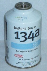
Can of DuPont R 134a refrigerant
Image – Refrigerant; Image Credit – Wikipedia

Question: – Describe the major difference between Carnot cycle and Rankine cycle.

Solution: – The major difference between Carnot cycle and Rankine cycle is discuss below,

Parameter Carnot Cycle Rankine Cycle
Definition Carnot cycle in not a practical cycle it’s a theoretical cycle. The efficiency of the carnot cycle is highest between difference of two temperature Rankine cycle in not a theoretical cycle it’s a practical cycle.
Ideal for Carnot cycle appropriate for heat engine. Rankine cycle is appropriate for vapor compression refrigeration cycle.
Efficiency Efficiency of carnot cycle is higher than the rankine cycle. Efficiency of rankine cycle is lower than the carnot cycle.
Heat rejection In Carnot cycle heat rejection is done when temperature stays at constant. In Rankine cycle heat rejection is done when pressure stays at constant.

Isentropic Efficiency Of Nozzle: What, How, Several Types, Examples

N2

The main purpose of using a nozzle is to accelerate the velocity of a flowing fluid using pressure. In this article we will discuss about Isentropic Efficiency of Nozzle.

Isentropic efficiency of nozzle is the ratio actual kinetic energy at nozzle exit and isentropic kinetic energy at nozzle exit for the same inlet and exit pressures.

A fluid accelerates in a nozzle as it is moving from high pressure to low pressure with an increase in kinetic energy. Frictional losses inside the nozzle decreases fluid KE and raise the temperature of the fluid, increasing its entropy.

isentropic efficiency of nozzle
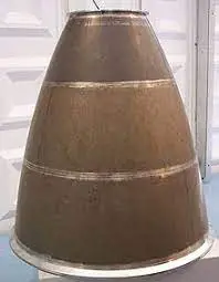
A nozzle from the Ariane 5 rocket; Image Credit: wikipedia

Nozzles are operated under adiabatic condition but the ideal process for a nozzle is the isentropic process. To have a comparison between actual work done and work under isentropic conditions of a device, a parameter called Isentropic Efficiency is used.

download 1
A water nozzle; Image credit: wikipedia

What Is Isentropic Efficiency of Nozzle?

The isentropic process involves no irreversibilities and serves as the ideal process for adiabatic devices.

Turbines, compressors and nozzles works under adiabatic conditions. Since they are not truly isentropic, they are considered as isentropic for calculation point of view. Isentropic efficiency is the parameter for a nozzle, turbine or compressor which defines how efficiently these devices approximate a corresponding isentropic device.

Nearer to an idealized isentropic process, improved will be the performance of the nozzle.

IsentropicEfficiency of nozzle is generally greater than 95%. So losses due to irreversibilities are very small in case of a well designed nozzle.

What is a Nozzle?

Nozzles are most widely used steady flow device in steam turbines, gas turbines and rockets.

Nozzle is a device often a pipe or a tube of varying cross sectional area used to control the direction of flow as well as exit velocity, mass, shape and pressure of the flow. Inside a nozzle pressure energy is converted into kinetic energy or we can say the fluid velocity increases with an expense of pressure energy.

Depending on required velocity and mach number of the fluid, Nozzles can be categorised like Convergent type, Divergent type and Convergent-Divergent type. Nozzle can be used for both subsonic and supersonic flows.

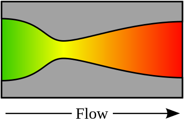
375px De laval nozzle.svg
A De Laval Nozzle; Image credit: Wikipedia

In the above figure, a de Laval nozzle, showing approximate flow velocity increasing from green to red in the direction of flow

Isentropic Efficiency of Nozzle Formula

Isentropic Efficiency represents the performance index of a nozzle. A comparison of nozzle’s performance relative to an isentropic process.

Isentropic Efficiency of Nozzle can be defined as the ratio of actual enthalpy drop to isentropic enthalpy drop between the same pressures.

Isentropic Efficiency of Nozzle=Actual enthalpy drop/Isentropic enthalpy drop

gif

Isentropic Efficiency formula is the measure of the deviation of actual processes from the corresponding idealized ones. The ratio of actual work done by a nozzle to work done by the nozzle under isentropic condition is called Isentropic Nozzle Efficiency.

Isentropic Efficiency of a nozzle ηN= Actual Kinetic Energy at Nozzle Exit/ Isentropic Kinetic Energy at Nozzle Exit.

gif

Theoretically the process inside the nozzle is considered as isentropic but due to frictional losses the process is irreversible.

Untitled
Enthalpy Entropy diagram for a flow inside a nozzle

Process 1-2:Isentropic Process

Process1- 2{}’:Actual Process

Efficiency of nozzle,

gif.latex?%5Ceta%20 %7Bnozzle%7D%3D%5Cfrac%7Bh %7B1%7D %7Bh %7B2%7D%7D%27%7D%7Bh %7B1%7D h %7B2%7D%7D.......

For Process 1-2, applying SFEE,

gif

 Or,

gif.latex?h %7B1%7D h %7B2%7D%3D%5Cfrac%7BV %7B2%7D%5E%7B2%7D V %7B1%7D%5E%7B2%7D%7D%7B2%7D..........

For Process 1- 2′, applying SFEE,

gif

Or,

gif.latex?h %7B1%7D %7Bh %7B2%7D%7D%27%3D%5Cfrac%7B%7BV %7B2%7D%7D%27%5E%7B2%7D V %7B1%7D%5E%7B2%7D%7D%7B2%7D.........

Now from Eq(1) substituting the values of h1 – h2 and h1 – h2` ,we get

gif.latex?%5Ceta%20 %7Bnozzle%7D%3D%5Cfrac%7B%7BV %7B2%7D%7D%27%5E%7B2%7D V %7B1%7D%5E%7B2%7D%7D%7BV %7B2%7D%5E%7B2%7D V %7B1%7D%5E%7B2%7D%7D......

Equation(1) and (4) are the formulas to calculate the Isentropic Efficiency of Nozzle.

How to Find Isentropic Efficiency of Nozzle?

A Nozzle reduces the pressure of the flow and at the same time speed up the flow to create a thrust.

Some amount of heat loss takes place from the steam due to the friction with the surface of the nozzle. Frictional effect also increases the dryness fraction of steam, because energy lost in friction is transferred into heat which tends to dry or super heat the steam.

In case of fluid dynamics, stagnation point denotes a point where local velocity of a fluid remains zero and isentropic stagnation state represents a state when a flow of fluid goes through reversible adiabatic deceleration to zero velocity.

Both actual and isentropic states are used for gases.

Enthalpy–entropy diagram illustrating the definition of stagnation state
Enthalpy Entropy Diagram for Stagnation State; Image credit: wikipedia

The actual stagnation state is obtained for actual deceleration to zero velocity, irreversibility may be also associated. For this reason stagnation property is sometimes reversed for actual state properties, and the term total property is applied for isentropic stagnation states.

Both isentropic and actual stagnation states have same enthalpy, same temperature(for ideal gas) but may be pressure is more in case of isentropic stagnation state in comparison to actual stagnation state.

In case of a nozzle the inlet velocity is negligible in comparison to exit velocity of  a flow.

From the energy balance,

gif

Isentropic Efficiency of Nozzle=Actual enthalpy drop/Isentropic enthalpy drop

gif

Where h1 =specific enthalpy of the gas at the entrance

h2a =specific enthalpy of gas at the exit for the actual process

h2s = specific enthalpy of gas at the exit for the isentropic  process

Isentropic Efficiency Nozzle Example

Example: Steam enters a nozzle at 1.4 MPa  2500 C and negligible velocity and expands to 115 KPa and a quality of 97% dry. Determine the exit velocity of the steam.

Solution: Given data , Initial Pressure, P1=1.4MPa

 =14 bar

Initial Temperature, T1=2500 C

Final Pressure,P2=115 KPa= 1.15 x 10⁵ Pa=1.15 bar

Quality of steam at exit, x2=0.97

Exit Velocity, V2=?

Neglecting initial velocity, Exit Velocity,

s

Considering initial velocity,

gif

h1=Enthalpy at initial condition i.e. at 1.14 MPa i.e at 14 bar 2500C, from steam tables,

h1=2927.6 KJ/Kg

h2=Enthalpy at exit condition i.e. at 115 KPa i.e at 1.15 bar x2=0.97, from steam tables

hf2=434.2 KJ/kg

hfg2=2247.4 KJ/kg

Kg

Hence the exit velocity of steam,

s

What Does A Crankshaft Sensor Do: How It Works

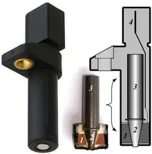
220px Crankshaft sensor

This article answers the question- what does a crankshaft sensor do? Crankshaft sensor is a device used in internal combustion engines to locate the position of crank and its velocity.

We shall discuss the working of an internal combustion engine first, then we shall continue our discussion further with crankshaft sensor and the working of crankshaft sensor. In later sections, we shall also read about different types of internal combustion engines.

What is an IC engine?

An internal combustion engine or IC engine is a heat engine inside which combustion takes place with the help of an oxidizer and working fuel.

IC engine converts this heat energy produced by the combustion of fuel-air mixture to mechanical energy. The main parts of IC engine include Piston, Cylinder, Crank, Spark plugs (In SI engine), crankshaft. We shall discuss more about internal combustion engines in the next section. 

Working of internal combustion engine

Internal Combustion engine is an assembly of various mechanical components that work in harmony to produce desired output.

During the intake stroke, the fuel is injected in the system. The piston is connected to connecting rod that connects piston and the crank. As the air fuel mixture is ignited, the piston moves at the bottom dead center and then comes back to the top dead. Due to reciprocating motion of the piston, the crank rotates and in turn helps the wheels to rotate.

How does a crankshaft sensor work?

A crankshaft sensor can be attached to an engine block facing towards the timing rotor or the ring gear attached on the crankshaft. The crankshaft has teeth whose positions are used to determine the actual position of crankshaft.

The sensor will keep a count of the number of teeth that have passed on the ring gear. This information is fed to the engine control unit or engine management system which then calculates the precise position of the crankshaft and decides when the switching on and off of different spark plugs.

what does a crankshaft sensor do
Image: Different crankshaft position sensors

Image credits: TamasflexCrankshaft sensorCC BY-SA 3.0

Crankshaft sensor use

The uses of crankshaft sensor are not many but every use is a very significant one. The uses of a crankshaft sensor are given in the section below-

  • Count the number of teeth passed and feed the information to the engine management system.
  • Locate the position of crankshaft.
  • The information about the position of crankshaft is then used to decide the switching on and off of different spark plugs.

Causes of crankshaft sensor failure

There are many causes of failure for a crankshaft sensor. The causes include the following-

  1. Damage– Due to a sudden jerk or excess pressure on the sensor, the sensor may get damaged. Some times the heat gets inside the sensor and melts few components. Such damages lead to crankshaft failure.
  2. Debris – Debris from other broken components can hinder the reading collection process and may lead to crankshaft sensor failure.
  3. Faulty circuitry– When the circuit connections are not proper, the readings from sensor will not be able to reach the engine management system. The sensor will not able to find the correction position of the crankshaft drive and hence the firing order of spark plugs will be uneven leading to more fuel consumption.

How are crankshafts made?

The crankshafts are usually made of steel. The manufacturing processes may vary but commonly they are made using die forging. If the material is cast iron then they are made by casting.4

In casting process, a mould is prepared using a pattern. Then molten cast iron is added to the mould and is left for solidification. Due to solidification, the actual size of casting reduces. To compensate for shrinkage due to solidfication, risers are provided. Risers will have extra molten metal that will be served to the mould in compensation of solidification shrinkage taking place inside the casting. 

Cam shaft position sensor

Two sensors- Camshaft position sensor and crankshaft position sensors work together to determine the exact location of the crankshaft. The readings from both of these sensors help the engine management system to find the exact time to know when the first cylinder is in the top dead centre.

The principle on which a cam shaft sensor works is the Hall principle. A rng gear is located on the crankshaft which has many teeth on its circumference. The sensor counts the number of teeth passing by while the ring gear is rotating. Number of teeth that have passed are counted (due to rotation of ring gear) and due to this rotation there is a change in voltage of Hall IC in the sensor head. The voltage change is converted to a readable reading that is the position of crankshaft, this translation is done by the engine management system. 

Sensor code P0340

The camshaft sensor simply helps us to determine the location of the crankshaft.

Without the help of this sensor, the engine will not know when to ignite fuel, this will lead to ncrease in consumption of fuel and sometimes this may lead to engine damage.

Sensor code P0340 symptoms

There are different methods by which we can identify P0340 code.

Major symptoms of code P0340 are-

  • Check engine light on dashboard
  • Poor acceleration
  • Engine stalling
  • Car jerking
  • Problems shifting gear
  • Low fuel mileage
  • Ignition problems

If you observe any of the above symptoms frequently in your vehicle then it is recommended to give the vehicle for servicing specifically targetting the sensor part.

Sensor code P0340 causes

The causes behind the setting of P0340 are given in the section below.

The following list shows the cause of P0340-

  • Defective sensor
  • Defective ring gear on the camshaft
  • Fault in crankshaft sensor
  • If the wiring inside crankshaft sensor circuit is damaged or corroded.

How serious is P0340?

An alarm alerts the user for any type of emergency situation arising in the system. There are different types of alarms depending upon the intensity of the problem occurring. If the alarm is ignored then it may lead to severe damage to the engine parts.

Initially the engine will start running erratically. The engine’s efficiency will be compromised and even mileage too. If this continue for a longer period of time and it is not treated properly then the engine can be damaged severely due to improper ignition timing.

Camshaft sensor code P0016

Another code relating to camshaft sensor is code P0016.

This is a generic OBD-II code that will indicate the camshaft position sensor about the bank 1 does not correlate to the signal from the crankshaft position sensor.

Symptoms of P0016 code

There are different methods by which we can identify P0016 code.

Some of the symptoms of P0016 code are-

  • Check engine light turns on.
  • Engine starts running erratically/abnormally.
  • The mileage of vehicle decreases due to more fuel consumption.
  • Reduction in power

Causes of P0016 code

 There are multiple ways by which this code can appear.

Major causes of P0016 are-

  • Oil control valve has restriction in Oil control valve filter
  • Camshaft timing is out of position.
  • Camshaft phaser is out of position because of fault with phaser.

How severe is P0016

As discussed for problems pertaining to code P0034, P0016 code has similar problems.

In both the cases the engine starts stalling or running erratically. This is followed by reduction in fuel mileage. And at the end it leads to severe damages to the engine. These damages depend upon the failed part.

What to do after replacing camshaft sensor?

The camshaft sensor must be installed in correct orientation. After orienting in the correct direction, one must reset the sensor before using the vehicle.

  • The procedure for resetting is very simple. The very first thing one has to do is to focus on switch ON and OFF function, these switches are connected to magnets that need to be adjusted first.
  • Then we need to check engine light, crank sensor, engine block and see if there is any damage. After doing all of this, trouble codes also need to be checked by code reader and see if there is any problem or not.
  • After completing the above step, we turn off all the parts that are connected to battery and start driving vehicle at 70 Kmph-80 Kmph for five minutes and then decelerate it to 50-60 kmph. This way the timing chain is changed or the sensor is reset.
  • If one still faces problems while resetting then he/she should definitely consult a mechanic to perform this procedure.

Deep Well Jet Pump Diagram: How It Works

This article discusses about deep well jet pump diagram. The reader need not have a pre requisite about jet pumps. In this article we shall study about jet pumps as well as deep well jet pump.

The word jet refers to a stream of fluid moving with high velocity and pressure. In this article we shall study about working of a jet pump, deep well jet pump diagram, applications of jet pump and different types of jet pumps available in the industry.

What is jet pump?

A jet pump is simply an assembly of a centrifugal pump, nozzle and a venturi. The jet pump gives out water at high velocity and pressure.

Venturi is used for creating a pressure difference due to which suction increases. We use nozzle to increase the pressure of fluid. In further sections we shall discuss about different types of jet pumps and working of jet pumps in detail.

What is a deep well jet pump?

A deep well jet pump is simply a jet pump that is used to draw waters having depth ranging from 25 ft- 110 ft. This is deeper than usual situations hence the name deep well jet pump.

The working of the deep well jet pump is same as a normal jet pump with the only difference being the diameter of impeller casing, greater the diameter greater the suction and hence greater the depths the jet pump can work on.

Deep well jet pump diagram

A deep water jet pump is used in deep wells. The diagram of deep well jet pump is given in the section below-

Image Credits: Diy.Stackexchange.com

How does a deep well jet pump work?

The working of a deep well jet pump is similar to a normal jet pump. In the section below we shall study about the working of a deep well jet pump.

In a deep well pump, the pipe which is connected to the impeller casing draws water inside the jet’s body that is located around 10-20 ft deep below the minimum well water level. A second pipe connects to the output of the pump. The centrifugal pump is an assembly of electric motor and impeller, when the motor starts moving the impeller connected to it also starts moving, creating a suction. Later when the fluid passes through venturi more pressure difference is created and the velocity of the fluid is increased.

Types of jet pump

There are two main types of jet pumps. The classification is done on the basis of depth of water that the pumps can draw. For shallow depths we have a different jet pump and for deep water we can use deep water jet pump.

We shall discuss about them in detail. They are given in the list below-

  1.  Shallow water jet pump- The name itself suggests that these pumps are used for shallow depths. They can work up to depth of 25 ft. The main idea behind a shallow water jet pump is that they have smaller impeller casings.
  2. Deep water jet pump– Deep water means that the depth of water is more than usual. The depths up to which deep water jet pump can work ranges from 25 ft to 110 ft.

Can you use a jet pump without using a pressure tank?

High pressure jets are used in jet pumps to displace the fluids from one place to another. While in almost every case, a jet pump uses pressure tank that provides high pressure to the stream.

The velocity of fluid is increased with the help of high pressure. The fluid is displaced using the pressure difference created inside the jet pump. However, we can use a jet pump without the help of a pressure tank. But it would cause wearing of the pump due to the pressure generated. So it is recommended to use a pressure tank in a jet pump. 

How far can a jet pump pull water?

We have studied about the different types of jet pumps and the depths at which they can be used. Theoretically, at ground levels the jet pump can pull water upto an average depth of 30 feet.

Near vacuum conditions can provide a lifting capacity upto 35 feet. The mentioned numbers are strictly for a shallow water jet pump. In real cases, due to many major losses, the number comes down to 25 feet! Mechanical losses and hydraulic losses contribute to reduction in this number.

Jet pump advantages and disadvantages

We have discussed in detail about the working of jet pump and its types. Now we shall discuss about the different advantages and disadvantages of using a jet pump.

The advantages and disadvantages of jet pump are given in the section given below-

Advantages

  • It has a great capability to provide high productivity.
  • Due to less mechanical parts in a jet pump, the chances of wear and tear are less.
  • The service life is very long.
  • The maintenance of this pump does not require much efforts and incurs less costs.
  • If we want to increase or decrease the productivity then with the help of a single injector we can achieve it.
  • The jet pump can run for longer durations without needing any assistance from us.
  • The jet pump has a very high tolerance against the abrasives present inside the fluid.

Disadvantages

  • Other artificial lifts are more efficient than jet pumps.
  • Space limitation is a major concern while using jet pumps.
  • Presence of very high pressure surface lines.
  • Very high power is consumed by jet pumps.

How does a jet pump work on a return fuel system?

Return fuel system is used in internal combustion engines, it comes with a hose that is connected with a carburettor. Sometimes excess fuel is left after a complete combustion cycle, this excess fuel is sucked in by the return fuel system.

Fuel is under high pressure inside the engine cylinder, due to the high pressure a suction is created due to the venturi action inside the pump. As a result of this, excess fuel is drawn towards the fuel tank. The fuel flows through auxilliary pipe system present inside the cylinder.

How does a two line jet pump work?

The name of this jet pump suggests that it uses two pipes. Larger pipe is used for upstream and smaller pipe for downstream.

The two line jet pumps are assisted by venturi that is situated at the bottom of pipes. Water is pumped upward using this venturi. Two line jet pumps can be used in wells, a lake or sometimes even in a water tank.

How does a convertible jet pump work?

This type of pump is versatile in nature. It is mainly used in applications like pumping water from lakes, wells or sprinkler systems.

The same principle that is used in jet engines is used in convertible jet pumps. In convertible jet pumps also, we use nozzle and venturi to pump the water. The internal components of a convertible jet pump is made up of thermo plastics and some times iron too. Since thermo plastics are weaker than iron, the iron parts are long lasting than those made up of thermo plastics.

How does a jet pump work for a jet ski?

We all can refer to jet ski as a water bike. It resembles a bike with the only difference that it runs on water. Jet ski can achieve high speeds, these speeds are achieved with the help of a jet pump.

The jet ski uses the third law of motion to move forward. When we apply the throttle, a centrifugal pump inside the jet ski starts moving as a result of which water is sucked in. The water is taken from the water body itself. The water passes through a nozzle and exits with a very high velocity. Due to high exit velocity the water pushes the jet ski in the forward direction.

How to Calculate Diffusion Coefficient: Guide for Beginners

diffusion coefficient is a crucial parameter used to quantify the rate of diffusion of a substance in a given medium. It is commonly used in various scientific fields, including physics, chemistry, and biology, to understand the movement and spread of particles or molecules. In this blog post, we will explore how to calculate diffusion coefficient, including different formulas, mathematical expressions, and experimental techniques.

How to Calculate Diffusion Coefficient

how to calculate diffusion coefficient
Image by Bhaveshkumar1995 – Wikimedia Commons, Wikimedia Commons, Licensed under CC BY-SA 4.0.
how to calculate diffusion coefficient
Image by Edudas – Wikimedia Commons, Wikimedia Commons, Licensed under CC BY-SA 4.0.

A. Overview of the Calculation Process

Calculating the diffusion coefficient involves determining the rate at which particles or molecules disperse in a medium over time. It provides insights into the behavior of substances in different conditions and helps analyze their transport properties. To calculate the diffusion coefficient, we need to consider factors such as time, displacement, and the properties of the medium.

B. Diffusion Coefficient Formula and its Components

The diffusion coefficient is obtained by dividing the mean square displacement MSD of the particles by the time elapsed. The formula for calculating the diffusion coefficient is as follows:


D = \frac{{\text{MSD}}}{6 \times t}

Where:
D represents the diffusion coefficient
text{MSD} is the mean square displacement
t is the time interval

The mean square displacement is calculated by measuring the average squared distance traveled by the particles over a given time period.

C. Step-by-step Guide to Calculate Diffusion Coefficient

To calculate the diffusion coefficient, follow these steps:

  1. Collect data: Record the positions of the particles at different time intervals.
  2. Calculate displacement: Determine the displacement of each particle from its initial position. The displacement is the difference between the final and initial positions.
  3. Square the displacement: Square the displacement of each particle.
  4. Find the average: Calculate the average of the squared displacements.
  5. Calculate the diffusion coefficient: Divide the average squared displacement by 6 times the time interval.

Let’s move on to exploring experimental methods of calculating the diffusion coefficient.

Calculating Diffusion Coefficient Experimentally

how to calculate diffusion coefficient
Image by Rosentod – Wikimedia Commons, Wikimedia Commons, Licensed under CC BY 3.0.

A. Preparation for the Experiment

Before conducting an experiment to calculate the diffusion coefficient, it is essential to set up the necessary apparatus and prepare the sample. The following steps can be followed:

  1. Select the medium: Choose an appropriate medium for the experiment, such as air, water, or a specific solution.
  2. Prepare the sample: Introduce the substance or particles into the medium in a controlled manner. This can be achieved through various methods, such as adding a drop of the substance into the medium or injecting it using a syringe.
  3. Set up the observation system: Arrange a suitable observation system to track the movement of the particles. This can be done using microscopy techniques or other tracking methods.

B. Conducting the Experiment

Once the preparation is complete, the actual experiment can be conducted. Here are the steps involved:

  1. Observe the particles: Start recording the positions of the particles at regular time intervals using the chosen observation system.
  2. Track the displacement: Determine the displacement of each particle from its initial position at each time interval.
  3. Calculate the mean square displacement: Square the displacement of each particle and calculate the average of the squared displacements.
  4. Measure the time interval: Note the time interval between each position measurement.

C. Analyzing the Results

After collecting the necessary data, it’s time to analyze the results and calculate the diffusion coefficient. Follow these steps:

  1. Find the average squared displacement: Calculate the average of the squared displacements obtained from the experiment.
  2. Determine the time interval: Note the time interval used in the experiment.
  3. Apply the diffusion coefficient formula: Use the formula (D = \frac{{\text{MSD}}}{6 \times t}) to calculate the diffusion coefficient, where (\text{MSD}) is the average squared displacement and (t) is the time interval.

By following these steps, you can experimentally calculate the diffusion coefficient of a substance in a given medium.

Calculating Specific Types of Diffusion Coefficients

A. How to Calculate Apparent Diffusion Coefficient

The apparent diffusion coefficient ADC is a measure of how molecules or particles diffuse in a heterogeneous medium. It accounts for variations in the diffusion process due to differences in the medium’s properties. To calculate the ADC, follow a similar approach as for the diffusion coefficient, but consider the specific characteristics of the heterogeneous medium.

B. How to Calculate Effective Diffusion Coefficient

The effective diffusion coefficient takes into account the influence of external factors, such as temperature, pressure, and concentration, on the diffusion process. It represents the overall diffusion behavior under specific conditions. To calculate the effective diffusion coefficient, incorporate the relevant parameters into the diffusion coefficient formula.

C. How to Calculate Chloride Diffusion Coefficient

The chloride diffusion coefficient measures the rate at which chloride ions move through a substance, typically concrete. It is essential for understanding the durability of concrete structures. The calculation involves conducting experiments specifically designed to measure the movement of chloride ions and applying the diffusion coefficient formula.

D. How to Calculate Diffusion Coefficient of Protein

To calculate the diffusion coefficient of a protein, specialized techniques such as fluorescence correlation spectroscopy or dynamic light scattering are often employed. These methods allow for the measurement of protein dynamics and enable the determination of the diffusion coefficient based on the obtained data.

Calculating Diffusion Coefficient Using Different Software

Various software packages provide tools for calculating the diffusion coefficient based on simulation or experimental data. Let’s explore how to calculate the diffusion coefficient using some commonly used software:

A. How to Calculate Diffusion Coefficient in VMD

VMD Visual Molecular Dynamics is a powerful software used for visualizing and analyzing molecular dynamics simulations. It provides tools to calculate the diffusion coefficient of molecules in a simulated system. By analyzing the trajectory data and applying suitable algorithms, VMD can accurately determine the diffusion coefficient.

B. How to Calculate Diffusion Coefficient in Matlab

Matlab, a popular programming language, is widely used for scientific computing and data analysis. It offers various functions and algorithms to calculate the diffusion coefficient from experimental data. By implementing the necessary calculations and analysis, Matlab can provide accurate results for different types of diffusion coefficients.

C. How to Calculate Diffusion Coefficient in Gromacs

Gromacs is a versatile molecular dynamics simulation software used for studying the behavior of molecules. It includes built-in tools for calculating the diffusion coefficient based on simulated trajectories. By utilizing Gromacs’ analysis capabilities, researchers can obtain reliable diffusion coefficient values for different systems.

Worked Out Examples

Let’s go through some worked-out examples to solidify our understanding of calculating diffusion coefficient:

A. Diffusion Coefficient Calculation Example

Suppose we have measured the mean square displacement of particles as 4.5 square units and the time interval as 2 seconds. To calculate the diffusion coefficient, we can use the formula D = \frac{{\text{MSD}}}{6 \times t}. Substituting the values, we get:


D = \frac{4.5}{6 \times 2} = 0.375 \, \text{units per second}

Therefore, the diffusion coefficient in this example is 0.375 units per second.

B. How to Calculate Diffusion Coefficient from MSD

If we are given the mean square displacement MSD of particles as 9 square units and the time interval as 3 seconds, we can calculate the diffusion coefficient by applying the formula D = \frac{{\text{MSD}}}{6 \times t}. Substituting the values, we get:

D = \frac{9}{6 \times 3} = 0.5 \, \text{units per second}

Hence, the diffusion coefficient in this case is 0.5 units per second.

C. Diffusion Coefficient from Velocity Autocorrelation Function

In some cases, the diffusion coefficient can also be obtained from the velocity autocorrelation function VACF. By analyzing the temporal correlation of particle velocities, it is possible to calculate the diffusion coefficient using specific mathematical methods. However, the detailed explanation of this technique goes beyond the scope of this blog post.

Common Mistakes and Misconceptions in Calculating Diffusion Coefficient

While calculating the diffusion coefficient, there are some common mistakes and misconceptions to be aware of. Some of them include:

  • Neglecting the time interval: It is crucial to accurately measure and consider the time interval between position measurements to obtain reliable diffusion coefficient values.
  • Incorrectly interpreting experimental data: Analyzing the results of experiments to calculate the diffusion coefficient requires attention to detail and proper understanding of the underlying principles.
  • Overlooking temperature and pressure effects: External factors such as temperature and pressure can significantly impact the diffusion process. Neglecting their influence may lead to inaccurate diffusion coefficient calculations.

By avoiding these mistakes and misconceptions, researchers can ensure more accurate and meaningful diffusion coefficient calculations.

Through this comprehensive exploration, we have gained a solid understanding of how to calculate diffusion coefficient. We have covered the calculation process, experimental techniques, specific types of diffusion coefficients, software-based calculations, and examples. Remember, the diffusion coefficient serves as a valuable parameter for studying the behavior of particles and molecules in different systems, contributing to the advancement of numerous scientific fields.

9 Thermal Insulator Examples:Facts Explained And Insights

thermal insulator

Thermal insulators reduce heat transfer. Examples include aerogel (R-value up to 10.3 per inch), vacuum insulated panels (R-value 45), fiberglass (R-value 2.2-2.7 per inch), polystyrene (R-value 3.6-5), and mineral wool (R-value 3.0-3.3). Each material’s effectiveness varies with thickness and application.Lets discuss few of thermal insulator in detail

9+ Thermal Insulator Examples are listed below,

Thermal Insulator Examples:-

Water:-

Water is an example of thermal insulator. The electrons which are present in the water they are engage to make chemical bonds for this reasons the electrons are not free to take part in the conduction of heat, for this reason heat could not flow through it. So, water works as a thermal insulator.

Thermal insulator examples
Image – Water;
Image Credit – Wikimedia Commons

Plastic:-

Plastic is a perfect example of thermal insulator. The electrons which are present in the plastic they are engage to make chemical bonds to each other for this reasons the electrons are not free to take part in the conduction of heat, for this reason heat could not flow through plastic. So, plastic is not good heat conductor it is good insulator.

The plastics types which perfect example of thermal insulator are polyester films, Mylar, Melinex.

Plastic Masks 01
Image – Plastic masks;
Image Credit – Wikimedia Commons

Paper:-

Paper is an example of thermal insulator. Dry papers electrons could not carry electrons just because of the electrons which are present in the dry papers they are engage to make chemical bonds to each other for this reasons the electrons are not free to take part in the conduction of heat, for this reason heat could not flow through paper.

600px Making a paper collage
Image – Paper;
Image Credit – Wikimedia Commons

Glass:-

Glassis an also example of thermal insulator. Thermal insulator means from where heat cannot flow one area to another area. The electrons of the glass could not carry electrons just because of the electrons which are present in the glass they are engage to make chemical bonds to each other for this reasons the electrons are not free to take part in the conduction of heat, for this reason heat could not flow through glass material.

glass from below
Image – Glass;
Image Credit – Wikimedia Commons

Styrofoam:-

Styrofoam is another example of thermal insulator. Thermal insulator material means from where heat cannot flow one area to another area among them Styrofoam is. The electrons of the Styrofoam could not carry electrons just because of the electrons which are present in the Styrofoam they are engage to make chemical bonds to each other for this reasons the electrons are not free to take part in the conduction of heat, for this reason heat could not flow through Styrofoam material.

800px Physical weathering styrofoam cup Lake MIchigan
Image – Styrofoam cup;
Image Credit – Wikimedia Commons

Dry air:-

Dry air is an example of thermal insulator. Density of the dry air is a vital factor which is affects a matters insulation capability.  Density is a physical parameter which depends upon the spacing of the intermolecular of the particles in a matter. For because of dry air is a gaseous matter it can spread particle configure resist heat convection to some degree.

Dry air electrons could not carry electrons just because of the electrons which are present in the dry air they are engage to make chemical bonds to each other for this reasons the electrons are not free to take part in the conduction of heat.

Dry cotton:-

Dry cotton is an example of thermal insulator. From the dry cotton heat cannot flow but from wet cotton heat can flow. Means dry cotton works at insulator and wet cotton works as heat conductor.

The electrons of the dry cotton could not carry electrons just because of the electrons which are present in the dry cotton they are engage to make chemical bonds to each other for this reasons the electrons are not free to take part in the conduction of heat in a system, for this reason heat could not flow through dry cotton material.

800px CSIRO ScienceImage 10736 Manually decontaminating cotton before processing at an Indian spinning mill
Image – Dry Cotton;
Image Credit – Wikipedia

Oil:-

Oil is another example of thermal insulator. The electrons of the oil could not carry electrons just because of the electrons which are present in the oil they are engage to make chemical bonds to each other for this reasons the electrons are not free to take part in the conduction of heat, for this reason heat could not flow through oil material.
The viscosity of the oil is also reason for thermal insulation. The relation between the viscosity and thermal conductivity is when the thermal conductivity is increases

b79e5a9480a6d1b0275857634456b23763f5eafa
Image – Oil;
Image Credit – SnappyGoat.com

Rubber:-

Rubber is an example of thermal insulator. The electrons of rubbers are same like another type of thermal insulators. The electrons of the rubber not free to carry electrons just because of the electrons which are present in the rubber they are engage to make chemical bonds to each other for this reasons the electrons are not free to take part in the conduction of heat, for this reason heat could not flow through rubber made materials.

e1c24bc427c81962929186bf2fa3aa65629c6584
Image – Rubber;
Image Credit – SnappyGoat.com

Frequent Asked Questions:-

Question: – Write the major difference points between the thermal conductor and thermal insulator.

Solution: – The major difference points between the thermal conductor and thermal insulator is discuss below,

ParameterThermal conductorThermal insulator
DefinitionThermal conductor can be explain as, the material which is allow to flow the heat from one are to another area.Thermal insulator can be explain as, the material which is not allow to flow the heat from one are to another area.
Examples1.Silver
2.Iron
3.Aluminium
4.Mercury
5.Brass
6.Copper
7.Bronze
8.Gold
9.Graphite  
1.Water
2.Plastic
3.Paper
4.Glass
5.Styrofoam
6.Dry air
7.Dry cotton
8.Diamond
9.Oil
10.Rubber  
Movement of electronsElectron of the materials can flow the heat one area to another without any limits.Electron of the materials cannot flow the heat one area to another.
Electric fieldExistDoesn’t exist
Applications1.Insulation
2.Phase change materials
3.Conductive polymers
4.Textiles
5.Batteries
6.Heat transfer fluids
7.Additive manufacturing 8.Automotive and Electric vehicles
1.Keep home temperature warm in winter season
2. Keep home temperature cool in summer season
3.Keep liquids cool
4. Keep liquids hot

Question: – Give two examples of Insulation Material.
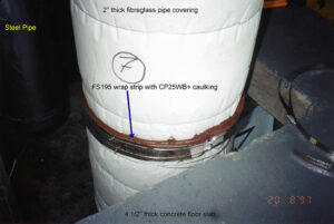
Solution: – The two examples of Insulation Material are,

Glasswool insulation material:-

Fiber glass insulation material is used almost everywhere. Fiber glass insulation material uses in residential and also in many commercial purposes, industrial applications. The fiber glass insulation material has extremely good quality glass fiber and ubiquitous insulation material. In industries many industrialist produce medium to high density fiber glass insulation material which are higher than the R values than the regular ones.
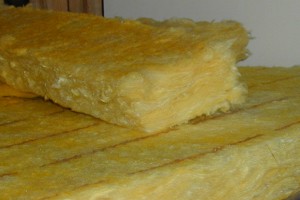
Benefit using of Fiber glass insulation material:-

  1. Eco friendly
  2. High thermal performance
  3. Light weight

Cellulose insulation materials:-

Cellulose insulation material is used in new buildings and old buildings, ceilings of the cathedral and walls for building cavities. Cellulose insulation material is made with recycled products mainly newspapers are used to make it. Near about 82 percentages to 85 percentages recycled products are used to make this process. In new type of construction cellulose insulation material is used as damp sprayed or dry sprayed.

Benefit using of Cellulose insulation material:-

  1. Eco friendly
  2. Economical
  3. Light weight
  4. Cost is not too high
  5. Non combustible
  6. Easy to install
  7. Maintenance is very less

Read more about Is Water An Insulator?

Drag Coefficient of Sphere: What, How, Examples

800px Drag coefficient of a sphere as a function of Reynolds number 300x185 1

In this article “Drag coefficient of sphere” will be discuss and drag coefficient of sphere related detailed facts will be also explain. Drag coefficient of sphere is very important factor for a matter.

Drag coefficient of sphere derive as, the ratio between the surface area of the sphere of the similar volume for the matter of the body comparative to the surface area for the matter of the body. Drag coefficient of sphere is a physical parameter which is deeply depends upon the shape and size of the matter.

What is the drag coefficient of a sphere?

800px Drag coefficient of a sphere as a function of Reynolds number
Image – Drag coefficient of a sphere as a function of Reynolds number; Image Credit – Wikimedia Commons

The drag coefficient of a sphere is depending upon the geometry of the matter and viscosity of the liquid substance through which the matter can flow.

Drag coefficient of sphere derive as, any sphere shaped matter is move in a motion through a liquid substance is facing the physical parameter of drag. The total amount of force is applied in same direction where shear stress force and pressure acted on the plane of the matter.

How to calculate drag coefficient of a sphere?

Drag pressure coefficient for a sphere shaped matter can calculated using this formula,

Where,

cd = Drag pressure coefficient for a sphere shaped matter

Fd = Drag force for a sphere shaped matter expressed in Newton

A = Plan form area for a for a sphere shaped matter expressed in square meter

ρ = Density of a sphere shaped matter express in kilogram per cubic meter

v = Viscosity a sphere shaped matter express in meter per second

Using the eqn (1) putting the values of mass density, flow speed, drag force and area we can get the value of drag coefficient of a sphere.

For sphere matter the area can be calculated as, A = π r2 ……..eqn (2)

The eqn (2) is applicable for the surface area. Because surface area formula is, A = 4 πr2

Drag coefficient of sphere formula:

The formula of the coefficient of pressure drag is given below,

gif
gif

Where,

Fd = Drag force express in Newton

cd = Drag coefficient

ρ = Density of a liquid substance express in kilogram per cubic meter

 v = Flow velocity of a liquid substance express in meter per second

A =Reference area for a particular body shape substance expressed in square meter

The pressure drag for sphere shape matter coefficient is dependent some several facts such as size and shape means geometry of the sphere body and viscosity of the liquid substance through which sphere shape matter can flow.

Drag coefficient of a sphere vs. Reynolds number:

The Drag coefficient of a sphere is decreases with the Reynolds number and drag coefficient becomes almost a constant (CD = 0.4) for a Reynolds number between 103 and 2×10⁵. As the Reynolds number increases (Re > 2×10⁵), the boundary layer becomes thinner in the front of the sphere and begins its transition to turbulent.

Drag coefficient of sphere
Image – Drag coefficient of a sphere vs. Reynolds number;
Image Credit – Wikipedia

When a system is design which is flow in a motion through a liquid substance that time drag is best for measurement for the system or calculate drag by a simulation. Drag coefficient is frequently helpful revert the data back for a particular analytical model.

The only problem is arising during this process that is one model is not appropriate to derive all type of flow of motion in liquid substance in the region of transition and for both regimes.

Instead of particular practice is use to measure and simulated data to calculate models in each and every flow type regime and after that follow where the models are intersect for calculate the region of transition.

Now we are going to discuss the examples and the Cf expression is consider for both pressure drag and skin friction drag.

Laminar Example:-

Drag coefficient of a sphere vs. Reynolds number for laminar flow can be written as,

Drag coefficient of a sphere vs. Reynolds number for laminar flow equation is perfectly goes with a wide range of Reynolds numbers in a closed system of geometries. Drag coefficient of a sphere vs. Reynolds number for laminar flow equation is not appropriate for low drag Reynolds number that could be less than 36 especially for incompressible or very near to incompressible flow.

In the incompressible or very near to incompressible flow we can observe drag coefficient is close to linear function of the velocity.

Turbulent Example:-

Drag coefficient of a sphere vs. Reynolds number for turbulent can be written as,

Drag coefficient of a sphere vs. Reynolds number for turbulent flow equation is perfectly goes with a one simple range of Reynolds numbers in a closed system of geometries.

Drag force coefficient of sphere:

The most studies case of the drag force coefficient is for sphere shaped matter of the body.

When a sphere shaped body in solid state interact with the fluid that time drag force coefficient is produced on the sphere shaped solid matter. Drag force coefficient of sphere matter is not produced by any type of force field.

Frequent Asked Questions:-

Question: –

Write about Skin Friction drag Coefficient.

Solution: –. Skin Friction drag coefficient is physical parameter which is dimensionless skin shear stress. It is mainly dimensionless because of the dynamic pressure is applied on the matter by the free stream.

Skin Friction drag coefficient formula is,

gif

Where,

Cf = Skin friction coefficient

Tw= Skin shear stress which is applied in the surface plane of the body

v = Free stream speed for velocity of the body

ρ = Free stream speed for density of the body

1/2ρ v2 ≡  q = Free stream dynamic pressure for the body of the matter

Relation with the Reynolds number and the Skin Friction drag coefficient is indirectly proportional to each other. Means if Reynolds number is increases then skin Friction drag coefficient decreases and if the Reynolds number is decreases then skin Friction drag coefficient is increases.

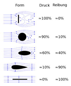
800px Form drag and skin friction ratio.svg
Image – Skin friction drag;
Image Credit – Wikimedia Commons

Laminar flow:-

Where,

Rex = ρ vx/μ Represent the Reynolds number

x = Represent the distance particularly from point of the reference at which the layers of boundary is started.

Transitional flow:-

Where,

gif
%5Crho%20%7D
gif

y = Represent the distance from the wall

u = The speed for the fluid which is flow in a motion and given as y

K1 = Karman Constant

The value of Karman Constant is lower than the 0.41 and Karman Constant is the value for transitional boundary layer and turbulent boundary layer

K2= Van Driest constant

K3= Pressure parameter

gif

p = Pressure

x = The coordinate along a surface where a boundary layers forms

Turbulent flow:-

Question: –

Riva drives her car daily Kolkata to Durgapur. When Riva drives her car that time the speed of the car is about 90 kilometres per hour and that time the drag coefficient is 0.35. The cross sectional area for the car is 6 square meter.

Now determine the amount of drag force.

Solution: – Given data are,

Velocity of the car = 90 kilometres per hour

Drag coefficient of the car = 0.35

Cross sectional area of the car = 6 square meter

Density of the fluid of the car = 1.2 kilogram per cubic meter

We all are know that the velocity of the air is, 1.2 kilogram per cubic meter

Now, applied Drag force formula,

gif

Where,

D = Pressure drag force

Cd= Pressure drag coefficient

ρ = Density

 v = Velocity

 A = Reference area

D = 0.35 * 1.2 * 8100 * 6 /2 * 3600

D = 2.8 Newton

Riva drives her car daily Kolkata to Durgapur. When Riva drives her car that time the speed of the car is about 90 kilometres per hour and that time the drag coefficient is 0.35. The cross sectional area for the car is 6 square meter.

The amount of drag force 2.8 Newton

Question: –

A plane is daily moves Mumbai to Katakana. When the plane moves that time the speed of the plane is about 750 kilometres per hour and that time the drag coefficient is 0.30. The cross sectional area for the car is 115 square meter.

Now determine the amount of drag force for the plane.

Solution: – Given data are,

Velocity of the plane = 750 kilometres per hour

Drag coefficient of the plane = 0.30

Cross sectional area of the plane = 115 square meter

Density of the fluid of the plane = 1.2 kilogram per cubic meter

We all are know that the velocity of the air is, 1.2 kilogram per cubic meter

Now, applied Drag force formula,

D = Cd * ρ * A/2

Where,

D = Pressure drag force

Cd = Pressure drag coefficient

ρ = Density

 v = Velocity

 A = Reference area

D = 3234 Newton

A plane is daily moves Mumbai to Katakana. When the plane moves that time the speed of the plane is about 750 kilometres per hour and that time the drag coefficient is 0.30. The cross sectional area for the car is 115 square meter.

The amount of drag force for the plane is 3234 Newton

Question: –

What is the relationship between drag and Reynolds number?

Solution: – The relationship between drag and Reynolds number is directly proportional to each other. Means if the drag is increases then Reynolds number is also increases and if the drag is deceases then Reynolds number is also decreases.

When Reynolds number is increases that time the viscous forces decreases relative to the internal forces so the point of separation moves in upward direction towards the equator.

7 Types of Insulation Material: Detailed Insights

800px Fs195 cp25 fibreglass pc 300x201 1

In modern generation a wide “Types of insulation material” are very easily available. In these article types of insulation material is prate and also types of insulation material relate facts are derived.

7+ Types of Insulation Material are listed below,

Example of 7+ Types of insulation material and their explanations:-

Glasswool insulation material:-

Glasswool insulation material is used almost everywhere starting from residential glasswool insulation material is used in many commercial purposes and also in industrial applications. The glasswool insulation material has extremely good quality glass fibre and ubiquitous insulation material.
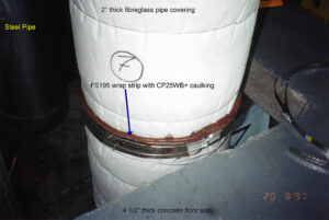
Glasswool insulation material is used in many form of insulation such as loose fill, blanket and also in duct insulation and rigid board. Glasswool insulation material is made with molten glass which is blown or spun into fibres. In most manufacturing industries for made this use 40 percent to 60 percent recycled glass material.

Types of insulation material
Image – Glasswool insulation material;
Image Credit – Wikipedia

Benefit using of Glasswool insulation material:-

  • Light weight
  • Flexible and resilient
  • Non combustible
  • Saves lots of energy
  • Easy to installation and also easy to handle
  • High thermal performance

Earthwool insulation material:-

Earthwool insulation material is generally made with Knauf insulation. Earthwool insulation material is made with a technology which name is ECOSE technology. This type of insulation material most use in residential, industrial and also in commercial.
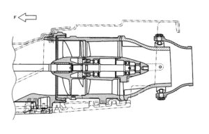
Benefit using of Earth insulation material:-

  • Non combustible
  • No smell is present in it
  • Long life
  • Acoustic product available
  • High thermal performance
  • Eco friendly
  • Low irritant product material

Rockwool insulation material:-

Rockwool insulation material is an artificial man made insulation material. In rockwool insulation material natural insulation minerals are used such as basalt or diabase. Near about 75 percent recycled materials are used in it. This material can withstand temperature of higher 1000 degree centigrade.

Benefit using of Rookwool insulation material:-

  • Fire resistance
  • High in durable
  • Non combustible
  • Long life
  • High thermal performance
  • High acoustic rating
  • Not affected by water

Polyester insulation material:-

Polyester insulation material is a transparent thermoplastic and it has no colour.  Polyester insulation material is mainly used for making beadboard insulation, loose fill insulation and concrete block insulation carrying small beads of polyester. Thermal resistance of polyester insulation material depend on its density.

In this material near about 50 percentages of recycled products are uses such as bottles of drinking. This type of material is made with heat any type of chemical binder not used in it.

Benefit using of Polyester insulation material:-

  • Non flammable
  • Non toxic
  • Irritant is not appear to touch this polyester insulation material
  • Long life
  • Non allergenic particles

Spray foam insulation material:-

Spray foam insulation material is an expensive material comparative to other insulation materials. For installation and maintenance trained people are used for this reason this insulation material became more expensive.

Benefit using of Spray foam insulation material:-

  • Eco friendly
  • Long life
  • Seal of the spray foam insulation material is airtight
  • Reduce energy bill
  • Help mould growth

Reflective insulation material:-

In the reflective insulation aluminium metal is used which also a reflective type material. Reflective foils are helps to increases the value of the thermal insulation by reflecting the heat to entering into the houses and buildings. The reflective insulation materials uses in for both commercial and residential applications.

Benefit using of Reflective insulation material:-

  • Cost is not too high
  • Non combustible
  • Easy to install
  • Maintenance is very less
  • Non degradable
  • Lightweight and thin
  • Hot climate cannot affect reflective insulation material

Insulation rigid insulation material:-

In the insulation rigid insulation process insulated materials are used such as Kraft paper, aluminium foil and white vinyl sheeting. The materials are used they all are vapour barrio and air barrier. A facing protects is used in insulation rigid insulation process thus insulation can hold together.

Benefit using of Insulated rigid insulation material:-

  • Hot climate cannot affect
  • Vapor and air does not affect on it
  • High thermal performance

Types of insulation material for wall:

The Types of insulation material for wall is listed below,

  1. Nu Wool insulation material
  2. Open cell spray insulation material
  3. Foil faced insulation material
  4. Flash and batt insulation material
  5. Foam board insulation material
  6. Fiberglass insulation material
  7. Wet applied cellulose insulation material

Types of insulation material for transformer:

The Types of insulation material for transformer is listed below,

  1. Pressboard
  2. Insulating tape
  3. Insulating paper
  4. Insulating oil
  5. Wood based laminates

Types of insulation materials of cables:

The types of insulation materials of cables is listed below,

  1. Nylon
  2. Polyurethane
  3. Plastic insulation
  4. Glass
  5. Teflon
  6. Paper

Types of insulation materials in buildings:

The insulation materials which are used in buildings listed below,

Fiber glass insulation materials:-

Fiber glass insulation material is used almost everywhere. Fiber glass insulation material uses in residential and also in many commercial purposes, industrial applications. The fiber glass insulation material has extremely good quality glass fibre and ubiquitous insulation material. In industries many industrialist produce medium to high density fiber glass insulation material which are higher than the R values than the regular ones.

800px Fs195 cp25 fibreglass pc
Image – Fiber glass insulation material; Image Credit – Wikipedia

Benefit using of Fiber glass insulation material:-

  • Eco friendly
  • High thermal performance
  • Light weight

Cellulose insulation materials:-

Cellulose insulation material is used in new buildings and old buildings, ceilings of the cathedral and walls for building cavities. Cellulose insulation material is made with recycled products mainly newspapers are used to make it. Near about 82 percentages to 85 percentages recycled products are used to make this process. In new type of construction cellulose insulation material is used as damp sprayed or dry sprayed.

Ecovata
Image – Cellulose insulation material; Image Credit – Wikipedia

Benefit using of Cellulose insulation material:-

  • Eco friendly
  • Economical
  • Light weight
  • Cost is not too high
  • Non combustible
  • Easy to install
  • Maintenance is very less

Mineral wool insulation materials:-

Mineral wool insulation material is made with recycled products mainly industrial products are used to make it. Near about 76 percentages recycled products are used to make this process. Rock wool and slag wool both are manmade products. Rock wool mainly made with natural product such as basalt and slag wool made with blast furnace slag.

Benefit using of Mineral wool insulation material:-

  • Eco friendly
  • Economical
  • Light weight
  • High thermal performance

Insulation facings insulation materials:-

Insulation facings insulation manufacturing process facings are fastened. The facing of the insulation a material protect the surface of the insulation and helps to hold the insulation together. Common material with are used in insulation manufacturing process are aluminium foil, kraft paper and white vinyl sheeting. Vapor barrier and air barrier does not affect on it at all.

Benefit using of Insulation of facings insulation material:-

  • Hot climate cannot affect
  • Vapor and air does not affect on it
  • High thermal performance
  • Eco friendly

Perlite insulation materials:-

The perlite insulation materials uses in very old type buildings. The material of perlite insulation is use as attic insulation. The perlite insulation carry small size and bulky pellets made with heating rock pellets.

Benefit using of Perlite insulation material:-

  • Low cost in install
  • Low maintenance
  • Light weight
  • Easy to install
  • Eco friendly

How Does A Jet Pump Work: Different Type Of Jet Pump And Facts

This article talks about how does a jet pump work. Pumps are normally used for sucking water from one place and transferring it to other place when the movement of water does not take place on its own.

There are many types of pumps which are used according to the requirements of the application. We cannot simply use any pump wherever we want to use. This article focuses only on the jet pump. We shall study what a jet pump is and how does it work and in what all applications the jet pump is used.

What is a pump?

A mechanical device that transfers the fluid from one place to another by utilising power in the form of electricity.

A pump is needed where the fluid won’t go itself, it will need an external source to take it from one place to another. This usually happens when the fluid moves from a lower potential to higher potential. Just like a ball cannot go up on its own and but it can come down on its own, the fluid also cannot go up on its own. It will need pump to get to the top.

What is a jet pump?

From many types of pumps present in the industry, we will study about the jet pump. The term jet suggests that it has a nozzle or small convergent area that will increase the velocity of the fluid.

The fluid velocity increases as a result of increasing pressure at the convergent area. The jet pump uses a centrifugal pump and injector. A high impulse stream is produced by the jet pump. In further sections we shall study about the different applications of jet pump and the simple working of jet pump.

How does a jet pump work ?

The main working prinicple of a jet pump is the venturi effect. The jet pump starts off as a conventional centrifugal pump.

The air inside the assembly is spilled out as soon as the pump starts, due to this a low pressure is created and hence the fluid is lifted up. The fluid right before entering the pump, passes through a venturi which increases the velocity of the fluid. Due to this a pressure difference is created again. This way the movement of water becomes more aggressive. This is how the jet pump works.

Jet pump working diagram

We have already discussed what a jet pump is and also discussed about its working. Now let us discuss about the working diagram of a jet pump.

In this section we will see the wroking diagram of a jet pump. The diagram below shows neat diagram of a jet pump.

How does a jet pump work
Image: Jet pump in a jet ski

Image credits: Wikipedia

How does a jet pump work for an oil well?

The jet pump is located at the bottom of an oil well. The jet pump is modified for the production of oil and gas production for making their production easier.

The main contents of a jet pump used in oil wells are- a diffuser, throat and nozzle. The main working fluid is pumped through the nozzle. This creates suction for the produced fluids. Now there are two fluids in the system- Suction fluids and produced fluids. These fluids are mixed inside the throat and the resulting mixture then passes through the diffuser.

How does a jet pump work for a jet ski?

Jet skis are used in water sports. They can be referred to as bikes running on water. They can achieve high speeds and this high speed can be achieved using a jet pump.

The jet ski moves forward using the third law of motion. As the throttle is applied, the pump starts moving and starts sucking water from the water body. The jet pump ejects the water with a high force. Due to third law of motion, an equal force is exerted on the jet ski, this opposite force is used to move forward.

How does a jet pump work on a return fuel system?

A return fuel system comes with a hose connected with a carburettor. The sole puprose of a return fuel system is that it sucks down the excess fuel sent in the system.

We all know that the fuel is at high pressure, this high pressure fuel creates a suction or venturi action inside the jet pump. This venturi action causes the excess fuel to be drawn out towards the fuel tank. The fuel is transported between the fuel tanks through the auxilliary pipe systems.

How does a two line jet pump work?

As the name suggests a two line jet pump uses two pipes, a larger pipe for upstream and a smaller pipe for downstream.

Two line jet pumps take the help of venturi that is situated at the bottom of the pipes. Through this venturi water is pumped upward. These can be used in wells, a lake or even a water tank.

How does a convertible jet pump work?

A convertible jet pump is a versatile pump mainly used for applications like pumping water from lakes, wells or sprinkler systems.

The principle used in jet engines is used in convertible jet pumps. In convertible jet pumps also, a nozzle and a venturi is used to pump the water. The convertible jet pumps have internal components made of thermo plastics and some times iron too. Since iron is stronger it is long lasting than the ones made of thermo plastics.

Types of jet pump

The jet pump is classified on the basis of depths that the pump can work in. Different types of jet pumps are designed for different types of depths. Below section tells us about the classification of jet pump in brief.

  1. Shallow water jet pump– As the name suggests, this type of jet pump is used to draw water of shallow depths. That is this jet pump can draw water out of a water column which is 25 feet deep.
  2. Deep water jet pump– The depth upto which a deep water jet pump can work on is between 25 feet to 110 feet. As the name suggests a deep water jet pump is used to draw water out of deep water columns.

Can you use a jet pump without using a pressure tank?

Jet pump works on the principle of high pressure jets that are used displace the water or any other fluid from one place to another. This high pressure is provided by pressure tanks some times. But these pumps do not necessarily need pressure tanks.

This pressure makes the flow of stream faster and displaces the targetted fluid. Although, a jet pump can work without a pressure tank also. This can be done in expense to wearing of the pump. Hence it is desirable to have a pressure tank in a jet pump.

What is a turbine pump?

A centrifugal pump that is installed underwater and is connected to an electric motor via shaft is known as a turbine pump. Its basic function is to pressurise the fluid and send it to the desired location to serve its purpose.

The efficiency of these pumps are very high and they are mainly used for large pumping applications. The pump works with various stages, analogous to a train being pulled by multiple engines because the load of train is so much that a single engine cannot drive. Turbo pumps are usually used inside rockets to pressurise the rocket fuel and oxidizer.