Hooke’s Law: 10 Important Facts

stress strain hooks 290x300 1

What is Hooke’s Law?

Hooke’s law basic properties:

The mechanical behaviour of materials depends on their response to loads, temperature, and the environment. In several practical problems, these controlling parameters’ combined effects must be assessed. However, the individual effects of loads (elastic and plastic deformation) must be studied in detail before attempting to develop an understanding of the combined effects of load and temperature or the effects of load and environment. The material response may also depend on the nature of the loading. When the applied deformation increases continuously with time (as in a tensile test), then reversible (elastic) deformation may occur at small loads before the onset of irreversible/plastic deformation at higher loads. Under reversed loading, the material may also undergo a phenomenon known as ”fatigue.”

Hooke’s Law Definition:

Robert Hooke law 1660. It states that the material’s deformations are directly proportional to the externally applied load on the material. 

According to Hooke’s law, the material behavior elastic can be explained as the displacements occurring in the solid material due to some force. The displacement is directly proportional to the force applied.

Does Hooke’s law include proportional limits or elastic limits?

Hooke’s law tell strain of the material is proportionate to the stress applied within the elastic limit of that material.

Stress-strain curve for Hooke’s law:

Stress :

The resistance offered by the body against deformation to the applied external force to the unit area is known as stress. The force is applied while stress is induced by the material. A loaded member remains in equilibrium when the externally applied load and the force due to deformation are equal.

\\sigma =\\frac{P}{A}

Where,

\\sigma= Intensity of stress,

  • P= Externally applied load
  • A= cross-sectional area

Unit of Stress:

The unit stress depends on the unit of External force and the cross-sectional area.

Force is expressed in Newton, and Area is expressed in m^2.

The unit of stress is N/m^2.

Types of stress:

Tensile stress:

The stress induced in the body due to the stretching of the externally applied load on the material.Results in an increase in the length of the material.

Compressive stress:

The stress induced in the body due to the shortening of the material.

Shear stress:

The stress occurred in the material due to the shearing action of external force.

Strain:         

When the body is subjected to external force, there is some change in the dimension of the body.

The strain is represented as the ratio of the change in dimension of the body to that of the original dimension of the body.

\\varepsilon =\\frac{\\Delta L}{L}

Unit of Strain

The strain is a dimensionless quantity.

Types of strain:

Tensile strain: 

The tensile strain is the strain induced due to the change in length.

Volumetric strain:

The volumetric strain is the strain induced due to the change in volume.

Shear strain:

The shear strain is the strain induced due to change in the area of the body.

Hooke’s law graph | Hooke’s law experiment graph

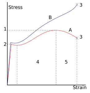
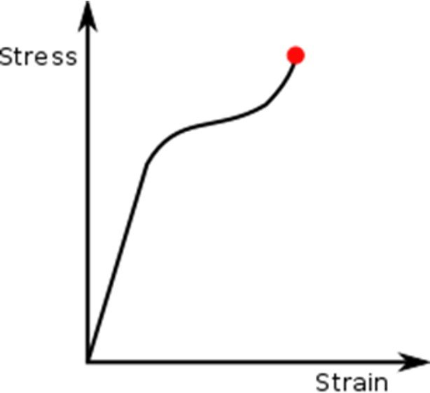
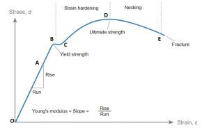
Hooke's Law: Stress-strain curve
Image credit:[User:Slashme] (David Richfield), Stress v strain A36 2, CC BY-SA 3.0

Robert Hooke studied springs and the elasticity of the springs and discovered them. The stress-strain curve for various materials has a linear region. Within the proportionality limit, the force applied to pull any elastic object is directly proportional to the displacement of the spring extension.

From the origin to proportionality limit material follows Hook’s Law. Beyond the elastic limit, the material loses its elasticity and behaves like plastic. When the material undergoes elastic limit, After removal of the applied force, the material goes back to its original position.

According to Hookes law stress is directly proportional to strain up to elastic limit but that stress vs strain curve is linear up to proportional limit rather than elastic limit Why ?

Which of these statements is correct All elastic materials follow Hookes law or materials that follow Hookes law are elastic ?

  • Answer:

All elastic materials does not follow Hook’s law. There are some elastic materials that does does not obey Hook’s law. so the first statement is invalid. But it is not necessity that materials that follow Hook’s law are elastic, In stress-strain curve for Hook’s law materials follow Hook’s law till their proportional limit and do possess elasticity. Every material has some elastic nature at certain limit and it can store elastic energy at certain point.

What is the difference between Hookes law and Youngs modulus ?

Hooke’s law of Elasticity :

When an external force is applied to the body, the body tends to deform. If the external force is removed and the body comes back to its original position. The tendency of the body to coming back to its original position after the removal of stress is known as elasticity. The body will regain its original position after the removal of stress within a certain limit. Thus there is a limiting value of force up to which and within which the deformation disappears completely. The stress that corresponds to this limiting force is an elastic limit of the material.

Young’s modulus | Modulus of Elasticity:

The proportionality constant between the stress and strain is known as young’s modulus and modulus of elasticity.

 \\sigma =E\\varepsilon

E= Young’s Modulus

What is an example of Hooke’s law ?

Hooke’s law spring:

An important component of automobile objects , the spring stores potential elastic energy when it is stretched or compacted. The spring extension is directly proportional to the applied force within the proportionality limit.

Mathematical representation of the Hooke’s law states that the applied force is equal to the K times the displacement,

F= -Kx

Hook’s law material elastic properties can only be explained when applied force is directly proportional to the displacement.

What is the name of the substance that does not obey Hooke’s law ?

Answer : Rubber

Does Hooke’s law fails in case of thermal expansion?

Answer : No

Hooke’s law stress strain | Hooke’s law for plane strain

Hooke’s law is important to understand the behaviour of the material when it is stretched or compressed. It is important to enhance the technology by understanding the material behaviour properties.

Hooke’s law equation stress strain

F=ma

σ=F/A

ε = Δl/l0

σ = E ε

F= -k * Δx

Strain is the ratio of total deformation or change in length to the initial length.

This relationship is given by ε = Δl/l0 where strain, ε, is change in l divided by initial length , l0 .

Why do we consider a spring massless in Hooke’s law ?

Hooke’s law is dependent on the spring extension and spring constant and is independent on the mass of the spring.so we consider spring massless in Hook’s law.

Hooke’s law experiment :

The Hooke’s law experiment performed to find out the spring constant of the spring. The original length of the spring before applying load is measured. Record the applied loads (F) in N and the corresponding lengths of the spring after extension. The deformation is the new length minus the original length before loads.

Since the force has the form

 F = -kx

Why is Hooke’s law negative ?

While representing hooks law for springs, the negative sign is always presented before the product of the spring constant and the deformation even though the force is not applied. The restoring force, which gives the deformation to the spring and the spring, is already in the opposite direction to that of the applied force. Thus, it is important to mention the direction of the restoring force while solving elastic material problems.

Derivation of Hooke’s Law:

Hooke’s Law equation:

F=-kx

Where,

  • F=Applied force
  • k=Constant for displacement
  • x = Length of the object
  • The use of k is dependent on the kind of elastic material, its dimensions and its shape.
  • When we apply a relatively large amount of applied force, the material deformation is larger.
  • Although, the material remains elastic as before and returns to its original size, and when we remove the force that we apply, it retains its shape. At times,

Hooke’s law describes the force of

F = -Kx

Here, F represents the equal and oppositely applied to restore, causing the elastic materials to get back to their original dimensions.

How is Hooke’s Law measured?

Hooke’s law units

SI units: N/m or kg/s2.

Hooke’s law spring constant

We can easily understand Hooke’s Law in connection with the spring constant. Moreover, this law states that the force required for compression or extension of a spring is directly proportional to the distance to which we compress or stretch it.

In mathematical terms, we can state this as follows:

F=-Kx

Here,

F represents the force that we apply in the spring. And x represents the compression or extension of the spring, which we usually expressed in metres.

Hooke’s law example problems

Let us understand this more clearly with the following example:

It stretches a spring by 50 cm when it has a load of 10 Kg. Find its spring constant.

Here, it has the following information:

Mass (m) = 10 Kg

Displacement (x) = 50cm = 0.5m

Now, we know that,

Force= mass x acceleration

=> 10 x 0.5= 5 N.

As per the Spring Constant formula

k = F/x

=> -5/0.5= -10 N/m.

Applications of Hooke’s law | Hooke’s law application in real life

  1. It is used in Engineering applications and physics.
  2. Guitar string
  3. Manometer
  4. spring scale
  5. Bourdon tube
  6. Balance wheel

Hooke’s law experiment discussion and conclusion

Limitation of Hooke’s law:

Hooke’s law is a first-order approximation to the response of the elastic bodies. It will eventually fail once the material undergoes compression or tension beyond its certain elastic limit without some permanent deformation or change of state. Many materials vary well before reaching the elastic limits.

Hook’s law is not a universal principle. It does not apply to all the materials. It applies to the materials having elasticity. And till the material capacity to stretch to a certain point from where they won’t regain their original position.

It is applicable until the elastic limit of the material. If the material is stretched beyond the elastic limit, plastic deformation takes place in the material.

The law can give exact answers only to the material undergoing small deformations and forces.

Hooke’s law and elastic energy:

Elastic Energy is the elastic potential energy due to the stored deformation of the stretching and compression of an elastic object, such as stretching and release of the spring. According to Hook’s law, the force required is directly proportional to the amount of stretch of the spring.

Hook’s Law: F= -Kx             — (Eq1)

The force applied is directly proportional to the extension and deformation of the elastic material. Thus,

Stress is directly proportional to strain as stress is the applied force to that of unit area and strain is deformation to that of the original dimension. The stress and strain considered are normal stress and normal strain.

In shearing stress,Material must be homogeneous and isotropic within its certain proportionality limits.

Shear stress represented as,

τxy = Gγxy —(Eq2)

Where,

  • τxy=shear stress
  • G=modulus of rigidity
  • γxy=shearing strain

This relation represents Hook’s law for shear stress. It is considered for the small amount of force and deformation. Material leads to failure if applied load larger force.

Considering material subjected to shearing stresses τyz and τzy, for small stress, the γxy will be the same for both the conditions and are represented in similar ways. The shear stresses within the proportional limit,

τxy = Gγxy —(Eqn3)

τxy = Gγxy —(Eqn4)

Case1: plain strain  where the strains in the z-direction are considered to be negligible,

\\varepsilon zz=\\varepsilon yz=\\varepsilon xz=0

the stress-strain stiffness relationship for isotropic and homogeneous material represented as,

1

The stiffness matrix reduces to a simple 3×3 matrix, The compliance matrix for the plane strain is found by inverting the plane strain stiffness matrix and is given by,

2

 Case2:Plane strain:

The stress-strain stiffness matrix expressed using the shear modulus G, and the engineering shear strain

\\gamma xy=\\varepsilon xy+\\varepsilon yx=2\\varepsilon xy is represented as,

4

The compliance matrix is,

5

Hooke’s law Problems:

States Hookes Law What is the spring constant of a spring that needs a force of 3 N to be compressed from 40 cm to 35 cm.

Hook’s law:

F= -Kx ,

3= -K (35-40)

K=0.6

A force of 1 N will stretch a rubber band by 2 cm Assuming that Hookes law applies how far will a 5 N force stretch the rubber band

Force is directly proportional to the amount of the stretch, According to Hook’s law:

F= -Kx

\\frac{F1}{F2}=\\frac{x1}{x2}

  F2=3cm

For more article click here
Reynolds Number: 21 Important Facts

Reynolds Number

Content

Reynolds number definition

“The Reynolds number is the ratio of inertial forces to viscous forces.”

The Reynolds number is a dimensionless number used to study the fluid systems in various ways like the flow pattern of a fluid, the flow’s nature, and various fluid mechanics parameters. The Reynold’s number is also important in the study of heat transfer. There are much correlation developed, including Reynold’s number in fluid mechanics, tribology and heat transfer. The preparation of various medicines in pharmacy required Reynold’s number study.

It is actually a representation and comparison of inertia force and viscous force.

Reynolds number equation

The dimensionless Reynold’s number represents whether the flowing fluid would be laminar flow or turbulent flow, considering to some properties such as velocity, length, viscosity, and flow type. The Reynold’s number has been discussed as follow:

The Reynold’s number is generally termed as the inertia force ratio to viscous force and characterize the flow nature like laminar, turbulent etc. Let’s see by the equation as below,

Re= \\frac{Inertia force}{viscous force}

Inertia force =\\rho A V^{2}

Viscous force = \\frac{\\mu V A}{D}

By putting the inertia force and viscous force expression in Reynold’s number expression, we get

Re = \\frac{\\\\rho V D}{\\mu }

In above equation,

Re = Reynold’s number (Dimensionless number)
? = density of fluid (kg / m3)

V = velocity of flow ( m/ s )

D = Diameter of flow or pipe/ Characteristics length ( m )

μ = Viscosity of fluid (N *s /m2)

Reynolds number units

The Reynold’s number is dimensionless. There is no unit of Reynolds number.

Reynolds number for laminar flow

The identification of flow can be possible by knowing the Reynold’s number. The Reynold’s number of laminar flow is less than 2000. In an experiment, if you get a value of Reynold’s number less than 2000, then you can say that the flow is laminar.

Reynolds number of water

The equation of Reynold’s number is given as

Reynolds number= \\frac{Density of fluid \\cdot velocity of flow\\cdot Diameter of flow/Length}{Viscosity of fluid}

If we analyze the above equation, the Reynolds number’s value depends on the density of fluid, velocity of flow, the diameter of flow directly and inversely with the viscosity of the fluid. If the fluid is water, then the density and viscosity of water are the parameters that directly depend on water.

laminar to turbulent convertion
laminar to turbulent
Image credit : brewbooks from near Seattle, USA, Laminar to Turbulent – Flickr – brewbooksCC BY-SA 2.0

Reynolds number for turbulent flow

Generally, the Reynolds number experiment can predict the flow pattern. If the value of Reynold’s number is >  4000, then the flow is considered as turbulent nature.

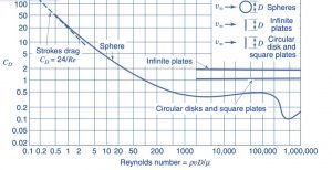
Drag Coefficient (Cd) vs Reynolds number (Re) in various objects

Renolds Number
Image credit : “File:Drag Coefficient (Cd) vs Reynolds number (Re) in various objects.png” by Welty, Wicks, Wilson, Rorrer. is licensed under CC BY-SA 4.0

Reynolds number in a pipe

If the fluid is flowing through the pipe, we want to calculate Reynold’s number of fluid flowing through a pipe. The other all parameters depends on the type of fluid, but the diameter is taken as pipe Hydraulics diameter  DH (For this, the flow should be properly coming out from the pipe)

Reynolds number= \\frac{Density of fluid \\cdot velocity of flow\\cdot Hydraulic Diameter of flow/Length}{Viscosity of fluid}

Reynolds number of air

As we have discussed in Reynold number for water, The Reynold number for air directly depends on air density and viscosity.

Reynolds number range

Reynold’s number is the criteria to know whether the flow is turbulent or laminar.

If we consider the flow is internal then,

If Re < (2000 to 2300) flow is considered laminar characteristics,

 Re > 4000 represents turbulent flow

If Re’s value is in between (i.e. 2000 to 4000)  represents transition flow.

Reynolds number chart

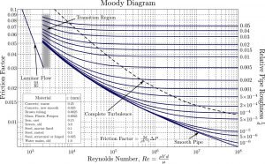
The moody chart is plotted between Reynolds number and friction factor for different roughness.

We can find the Darcy-Weisbach friction factor with Reynold number. There is an analytical correlation developed to find the friction factor.

Reynolds number
Reynold’s number in Moody Diagram Wikipedia
Credit Original diagram: S Beck and R Collins, University of Sheffield (Donebythesecondlaw at English Wikipedia) Conversion to SVG: Marc.derumauxMoody ENCC BY-SA 4.0

Reynolds number kinematic viscosity

The kinematic viscosity is given as,

Kinematic viscosity = \\frac{Viscosity of fluid}{Density of fluid}

The Equation of Reynold’s number,

Reynolds number= \\frac{Density of fluid \\cdot velocity of flow\\cdot Hydraulic Diameter of flow/Length}{Viscosity of fluid}

The above equation is formed as below if write it in the form of kinematic viscosity,

[Reynolds number= \\frac{velocity of flow\\cdot Hydraulic Diameter of flow/Length}{Kinematic Viscosity of fluid}

Re =\\frac{VD}{\ u }

Reynolds number cylinder

If the fluid is flowing through the cylinder and we want to calculate Reynold number of fluid flowing through the cylinder. The other all parameters depends on the type of fluid, but the diameter is taken as Hydraulics diameter DH (For this, the flow should be properly coming out from the cylinder)

Reynolds number mass flow rate

We then analyse the Reynold’s number equation if we want to see the relationship between the Reynold’s number and mass flow rate.

Re = \\frac{\\rho V D}{\\mu }

As we know from the continuity equation, the mass flow rate is expressed as below,

m =\\rho \\cdot A\\cdot V

By putting values of mass flow rate in the Reynolds number equation,

Re =\\frac{m\\cdot D}{A\\cdot \\mu }

It can be clearly noted from the above expression that the Reynold’s number has a direct relation with the mass flow rate.

Laminar vs turbulent flow Reynolds number | Reynolds number laminar vs turbulent

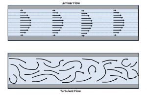
Generally, in fluid mechanics, we are analyzing two types of flow. One is the laminar flow which occurs at low velocity, and another is the turbulent flow which generally occurs at high velocity.  Its name describes the laminar flow as the fluid particles flow in the lamina (linear) throughout the flow. In turbulent flow, the fluid travels with random movement throughout the flow.

Let’s understand this important point in detail,

Laminar and Turbulent
Reynolds number for Laminar and Turbulent flow
Image credit :JoseasorrentinoTransicion laminar a turbulentoCC BY-SA 3.0

Laminar Flow

In laminar flow, the adjacent layers of fluid particles do not intersect with each other and flows in parallel directions is known as laminar flow.

In the laminar flow, all fluid layers flow in a straight line.

  • There possibility of occurrence of laminar flow when the fluid flowing with low velocity and the diameter of the pipe is small.
  • The fluid flow with a Reynold’s number less than 2000 is considered laminar flow.
  • The fluid flow is very linear. There is the intersection of adjacent layers of the fluid, and they flow parallel to each other and with the surface of the pipe.
  • In laminar flow, the shear stress only depends on the fluid’s viscosity and independent of the density of the fluid.

Turbulent Flow

The turbulent flow is opposite to the laminar flow. Here, In fluid flow, the adjacent layers of the flowing fluid intersect each other and do not flow parallel to each other, known as turbulent flow.

The adjacent fluid layers or fluid particles are not flowing in a straight line in a turbulent flow. They flow randomly in zigzag directions.

  • The turbulent flow is possible if the velocity of the flowing fluid is high, and the diameter of the pipe is larger.
  • The value of the Reynold’s number can identify the turbulent flow. If the  value of Reynold’s number is more than 4000, then the flow is considered a turbulent flow.
  • The flowing fluid does not flow unidirectional. There is a mixing or intersection of different fluid layers, and they do not flow in parallel directions to each other but intersecting each other.
  • The shear stress depends on its density in a turbulent flow.

Reynolds number for flat plate

If we analyse the flow over a flat plate, then the Reynolds number is calculated by the flat plate’s characteristics length.

Re = \\frac{\\rho V L}{\\mu }

In the above equation, Diameter D is replaced by L, which is the characteristics length of flow over a flat plate.

Reynolds number vs drag coefficient

Suppose the Reynold’s number’s value is lesser than the inertia force. There is a higher viscous force getting dominance on inertia force.

If the fluid viscosity is higher, then the drag force is higher.

Reynolds number of a sphere

If you want to calculate it for this case, the formula is

Re = \\frac{\\rho V D}{\\mu }

Here, Diameter  D is taken as Hydraulics diameter of a sphere in calculations like cylinder and pipe.

What is Reynolds number?

Reynold’s number is the ratio of inertia force to viscous force. Re indicates it. It is a dimensionless number.

Re= \\frac{Inertia force}{viscous force}

Significance of Reynolds number | Physical significance of Reynolds number

Reynold number is nothing but comparing of two forces. One is the inertia force, and the second is the viscous force. If we take both force ratio, it gives a dimensionless number known as Reynold number. This number helps to know flow characteristics and know which of the two forces impacts more on flow. The Reynold number is also important for flow pattern estimation.

   Viscous force -> Higher -> Laminar flow -> Flow of oil

   Inertia Force -> Higher -> Turbulent flow > Ocean waves

Reynolds experiment

Osborne Reynolds first performed the Reynolds experiment in 1883 and observe the water motion is laminar or turbulent in pattern.

This experiment is very famous in fluid mechanics. This experiment is widely used to determine and observe the three flow. In this experiment, the water flows through a glass tube or transparent pipe.

The dye is injected with water flow in a glass tube. You can notice the flow of dye inside the glass tube. If the dye has a different colour than water, it is clearly observable. If the dye is flowing inline or linear, then the flow is laminar. If it dye shows turbulence or not flowing in line, we can consider the turbulent flow. This experiment is simple and informative for students to learn about flow and Reynolds number.

Critical Reynolds number

The critical Reynolds number is the transition phase of laminar and turbulent flow region. When the flow is changing from laminar to turbulent, the Reynold’s number reading is considered a critical Reynold’s number. It is indicated as ReCr.  For every geometry, this critical Reynold’s number will be different.

Conclusion

Reynolds number is important terms in the field of engineering and science. It is used in study of flow, heat transfer, pharma etc. We have elaborated this topic in detail because of its importance. We have included some practical questions and answers with this topic.

For more articles on the related topics click here , Please find below

Polytropic Process : 11 Important Concepts

image 13

Definition Polytropic process

“A polytropic process is a thermodynamic process that obeys the relation: PVn = C, where where p is the pressure, V is volume, n is the polytropic index, and C is a constant. The polytropic process equation can describe multiple expansion and compression processes which include heat transfer.”

Polytropic Equation | Polytropic equation of state

The polytropic process can be defined by the equation

PV^n=C

the exponent n is called polytropic index. It depends upon the material and varies from 1.0 to 1.4. This is constant specific heat procedure, in which heat absorption of gas taken into consideration because of unit rise in temperature is fixed.

Polytropic process index

Polytropic index

Some important relations between Pressure [P], Volume [V] and temperature [T] in Polytropic process for an Ideal Gas

Polytropic equation is,

PV^n=C

\\\\P_1V_1^n=P_2V_2^n\\\\ \\\\\\frac{P_2}{P_1}=[\\frac{V_1}{V_2}]^n

………………………. Relations between Pressure [P] and Volume [V]

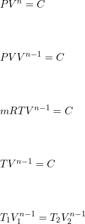
\\\\PV^n=C\\\\ \\\\PVV^{n-1}=C\\\\ \\\\mRTV^{n-1}=C\\\\ \\\\TV^{n-1}=C\\\\ \\\\T_1 V_1^{n-1}=T_2 V_2^{n-1}

\\frac{T_2}{T_1}=[\\frac{V_1}{V_2}]^{n-1}

………………………. Relations between Volume [V] and Temperature [T]

\\frac{T_2}{T_1}=[\\frac{P_2}{P_1}]^\\frac{n-1}{n}

………………………. Relations between Pressure [P] and Temperature [T]

Polytropic Work

Ideal gas equation for polytropic process is given by

\\\\W=\\int_{1}^{2}Pdv\\\\ \\\\W=\\int_{1}^{2}\\frac{C}{V^n}dv\\\\ \\\\W=C[\\frac{V^{-n+1}}{-n+1}]^2_1\\\\ \\\\W=\\frac{P_1V_1V_1^{-n+1}-P_2V_2V_2^{-n+1}}{n-1}\\\\ \\\\W=\\frac{P_1V_1-P_2V_2}{n-1}

Polytropic Heat transfer

According to 1st law of thermodynamics,

dQ=dU+W

\\\\dQ=mC_v [T_2-T_1 ]+\\frac{P_1 V_1-P_2 V_2}{n-1}\\\\ \\\\dQ=\\frac{mR}{\\gamma -1} [T_2-T_1 ]+\\frac{P_1 V_1-P_2 V_2}{n-1}\\\\ \\\\dQ=\\frac{P_1 V_1-P_2 V_2}{\\gamma-1}+\\frac{P_1 V_1-P_2 V_2}{n-1}\\\\ \\\\dQ=P_1 V_1 [\\frac{1}{n-1}-\\frac{1}{\\gamma-1}]-P_2 V_2 [\\frac{1}{n-1}-\\frac{1}{\\gamma-1}]\\\\ \\\\dQ=\\frac{\\gamma -n}{\\gamma -1}\\frac{P_1 V_1-P_2 V_2}{n-1}\\\\ \\\\dQ=\\frac{\\gamma -n}{\\gamma -1}W_{poly}

Polytropic vs isentropic process

Polytropic process is a thermodynamic process which follows the equation

PVn = C

This process takes into consideration the frictional losses and irreversibility factor of a process. It is a real-life actual process followed by the gas under specific conditions.

Isentropic Process also known as reversible Adiabatic process is an ideal process in which no energy transfer or heat transfer takes place across the boundaries of the system. In this process system is assumed to have an insulated boundary. Since Heat transfer is zero. dQ = 0

According to first law of thermodynamics,

\\Delta U=-W=\\int Pdv

Polytropic process vs adiabatic process

Polytropic process is a thermodynamic process which follows the equation

PVn = C

This process takes into consideration the frictional losses and irreversibility factor of a process. It is a real-life actual process followed by the gas under specific conditions.

Adiabatic process is a special and specific condition of polytropic process in which  .

Similar to Isentropic process in this process too, no energy transfer or heat transfer takes place across the boundaries of the system. In this process system is assumed to have an insulated boundary.

Polytropic efficiency

“Polytropic Efficiency well-defined as the ratio of Ideal work of compression for a differential pressure change in a multi-stage Compressor, to the Actual work of compression for a differential pressure change in a multi-stage Compressor.”

In simple terms it is an isentropic efficiency of the process for an infinitesimally small stage in a multi-stage compressor.

\\eta_p=\\frac{\\frac{\\gamma-1}{\\gamma}ln\\frac{P_d }{P_s}}{ln\\frac{T_d }{T_s}}

Where,  γ = Adiabatic index

Pd = Delivery Pressure

Ps = Suction Pressure

Td = Delivery Temperature

Ts = Suction temperature

Polytropic head

Polytropic Head can be defined as the Pressure Head developed by a centrifugal compressor as the gas or air is being polytropically compressed. The amount of pressure developed depends upon the density of the gas is compressed and that varies with variation in density of gas.

H_p=53.3*z_{avg}*\\frac{T_s}{S}(\\frac{\\gamma \\eta _p}{\\gamma -1})[(\\frac{P_d}{P_s})^\\frac{\\gamma -1}{\\gamma \\eta _p}-1]

Where,  

γ= Adiabatic index

 zavg = Average compressibility factor

η = Polytropic efficiency

Pd = Delivery Pressure

Ps = Suction Pressure

S = Specific gravity of gas

Ts = Suction temperature

Polytropic process for air | Polytropic process for an ideal gas

Air is assumed to be an Ideal gas and thus the laws of ideal gas is applicable to air.

Polytropic equation is,

PV^n=C

\\\\P_1V_1^n=P_2V_2^n\\\\ \\\\\\frac{P_2}{P_1}=[\\frac{V_1}{V_2}]^n

………………………. Relations between Pressure [P] and Volume [V]

\\\\PV^n=C\\\\ \\\\PVV^{n-1}=C\\\\ \\\\mRTV^{n-1}=C\\\\ \\\\TV^{n-1}=C\\\\ \\\\T_1 V_1^{n-1}=T_2 V_2^{n-1}

\\frac{T_2}{T_1}=[\\frac{V_1}{V_2}]^{n-1}

………………………. Relations between Volume [V] and Temperature [T]

\\frac{T_2}{T_1}=[\\frac{P_2}{P_1}]^\\frac{n-1}{n}

………………………. Relations between Pressure [P] and Temperature [T]

Polytropic process examples

1. Consider a polytropic process having polytropic index n = (1.1). Initial conditions are: P1 = 0, V1 = 0 and ends with P2= 600 kPa, V2 = 0.01 m3. Evaluate the work done and Heat Transfer.

Answer: Work done by Polytropic process is given by

 \\\\W=\\frac{P_1V_1-P_2V_2}{n-1}

 \\\\W=\\frac{0-600*1000*0.01}{1.1-1}=60kJ

Heat Transfer is given by

dQ=\\frac{\\gamma -n}{\\gamma -1}W_{poly}

\\\\dQ=\\frac{1.4 -1.1}{1.4 -1}*60=45\\;kJ

 2. A piston-cylinder contains Oxygen at 200 kPa, with volume of 0.1 m3 and at 200°C. Mass is added at such that the gas compresses with PV1.2 = constant to a final temperature of 400°C. Calculate the work done.

Ans: Polytropic work done is given by

 \\\\W=\\frac{P_1V_1-P_2V_2}{n-1}\\\\W=\\frac{mR[T_2-T_1]}{n-1}

\\\\\\frac{P_1V_1}{T_1} =mR \\\\mR=\\frac{200*10^3*0.1}{200}\\\\ \\\\mR=100 J/(kg. K) \\\\ \\\\W=\\frac{100*[400-200]}{1.22-1}\\\\ \\\\W=90.909 kJ

3. Consider Argon at 600 kPa, 30°C is compressed to 90°C in a polytropic process with n = 1.33. Find the work done on the Gas.

Ans: Polytropic work done is given by

 \\\\W=\\frac{P_1V_1-P_2V_2}{n-1}\\\\W=\\frac{mR[T_2-T_1]}{n-1}

for Argon at 30°C is 208.1 J/kg. K

Assuming m = 1 kg

work done is

 W=\\frac{1*208.1[90-30]}{1.33-1}\\\\ \\\\W=37.836\\;kJ

4. Assume mass of 10kg of Xenon is stored in a cylinder at 500 K, 2 MPa, expansion is a Polytropic process (n = 1.28) with final pressure 100 kPa. Calculate the work done. Consider the system has constant specific heat.

Ans: Polytropic work done is given by

 \\\\W=\\frac{P_1V_1-P_2V_2}{n-1}\\\\W=\\frac{mR[T_2-T_1]}{n-1}

We know that,

\\frac{T_2}{T_1}=[\\frac{P_2}{P_1}]^\\frac{n-1}{n}

\\\\\\frac{T_2}{500}=[\\frac{100}{2000}]^\\frac{1.28-1}{1.28} \\\\\\\\T_2=259.63\\;K

for Xenon at 30°C is 63.33 J/kg. K

Assuming m = 10 kg

work done is

 \\\\W=\\frac{10*63.33*[259.63-500]}{1.28-1}\\\\ \\\\W=-543.66\\;kJ

5. Take into consideration a cylinder-piston having initial volume 0.3 containing 5kg methane gas at 200 kPa. The gas is compressed polytropically (n = 1.32) to a pressure of 1 MPa and volume 0.005 . Calculate the Heat transfer during the process.

Ans: Polytropic Heat Transfer is given by

dQ=\\frac{\\gamma -n}{\\gamma -1}\\frac{P_1V_1-P_2V_2}{n-1}

\\\\dQ=\\frac{1.4-1.32}{1.4 -1}\\frac{100*1000*0.3-10^6*0.005}{1.32-1} \\\\\\\\dQ=15.625\\;kJ

6. Take into consideration a cylinder-piston containing 1kg methane gas at 500 kPa, 20°C. The gas is compressed polytropically to a pressure of 800 kPa. Calculate the Heat Transfer with exponent n = 1.15.

Ans: Polytropic Heat Transfer is given by

dQ=\\frac{\\gamma -n}{\\gamma -1}\\frac{P_1V_1-P_2V_2}{n-1}

dQ=\\frac{\\gamma -n}{\\gamma -1}\\frac{mR[T_2-T_1]}{n-1}

We know that, R for methane = 518.2 J/kg. K

\\frac{T_2}{T_1}=[\\frac{P_2}{P_1}]^\\frac{n-1}{n}

\\\\\\frac{T_2}{20+273}=[\\frac{800}{500}]^\\frac{1.15-1}{1.15}\\\\\\\\T_2=311.52\\;K

\\\\dQ=\\frac{1.4 -1.15}{1.4 -1}\\frac{1*518.2*[311.52-293]}{1.15-1}\\\\\\\\dQ=39.997\\;kJ

7. 1 kg of Helium is stored in a piston – cylinder arrangement at 303 K, 200 kPa is compressed to 400K in a reversible polytropic process with exponent n = 1.24. Helium is an ideal gas characteristics so specific heat will be fixed. Find the work and Heat Transfer.

Ans: Polytropic work done is given by

 \\\\W=\\frac{P_1V_1-P_2V_2}{n-1}\\\\W=\\frac{mR[T_2-T_1]}{n-1}

R for Helium is 2077.1 J/kg

 \\\\W=\\frac{2077.1*[400-303]}{1.24-1}=839.494\\;kJ

Polytropic Heat Transfer is given by

dQ=\\frac{\\gamma -n}{\\gamma -1}W_{poly}

dQ=\\frac{1.4 -1.24}{1.4 -1}*839.494=335.7976\\;kJ

8.Assume air stored in a cylinder having volume of 0.3 Liters at 3 MPa, 2000K. Air expands following a reversible polytropic process with exponent, n = 1.7, a volume ratio is observed as 8:1 in this case. Calculate the polytropic work for the process and compare it with adiabatic work if the expansion process follows reversible adiabatic expansion.

Ans: We are given with

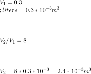
\\\\V_1=0.3 \\;liters=0.3*10^{-3} m^3\\\\ \\\\V_2/V_1 =8\\\\ \\\\V_2=8*0.3*10^{-3}=2.4*10^{-3} m^3

Relations between Pressure [P] and Volume [V]

\\\\P_1V_1^n=P_2V_2^n\\\\ \\\\\\frac{P_2}{P_1}=[\\frac{V_1}{V_2}]^n

 \\\\\\frac{P_2}{3}=[\\frac{0.3}{2.4}]^{1.7}\\\\\\\\P_2=0.0874\\;MPa

Polytropic work done is given by

\\\\W=\\frac{P_1V_1-P_2V_2}{n-1}

\\\\W=\\frac{3*10^6*0.3*10^{-3}-0.0874*10^6*2.4*10^{-3}}{1.7-1}=986.057\\;kJ

Adiabatic work done is given by

\\\\W=\\frac{P_1V_1-P_2V_2}{\\gamma-1}

\\\\W=\\frac{3*10^6*0.3*10^{-3}-0.0874*10^6*2.4*10^{-3}}{1.4-1}=1725.6\\;kJ

For expansion process the Work done through reversible adiabatic process is greater than the Work done through reversible Polytropic process.

9. A closed container contains 200L of gas at 35°C, 120 kPa. The gas is in compressng in a polytropic process till it reaches to 200°C, 800 kPa. Find the polytropic work done by the air for n = 1.29.

Ans: Relations between Pressure [P] and Volume [V]

\\\\P_1V_1^n=P_2V_2^n\\\\ \\\\\\frac{P_2}{P_1}=[\\frac{V_1}{V_2}]^n

 \\\\\\frac{800}{120}=[\\frac{200}{V_2}]^{1.29} \\\\\\\\V_2=45.95\\;L

Polytropic work done is given by

\\\\W=\\frac{P_1V_1-P_2V_2}{n-1}

\\\\W=\\frac{120*1000*200*10^{-3}-800*1000*45.95*10^{-3}}{1.29-1}=-44\\;kJ

10. A mass of 12 kg methane gas at 150°C, 700 kPa, undergoes a polytropic expansion with n = 1.1, to a final temperature of 30°C. Find the Heat Transfer?

Ans: We know that, R for methane = 518.2 J/kg. K

Polytropic Heat Transfer is given by

dQ=\\frac{\\gamma -n}{\\gamma -1}\\frac{P_1V_1-P_2V_2}{n-1}

dQ=\\frac{\\gamma -n}{\\gamma -1}\\frac{mR[T_2-T_1]}{n-1}

dQ=\\frac{1.4-1.1}{1.4 -1}\\frac{12*518.2*[30-150]}{1.1-1}=-5.596\\;MJ

11. A cylinder-piston Assembly contains R-134a at 10°C; the volume is 5 Liters. The Coolant is compressed to 100°C, 3 MPa Following a reversible polytropic process. calculate the work done and Heat Transfer?

Ans: We know that, R for R-134a = 81.49 J/kg. K

Polytropic work done is given by

W=\\frac{mR[T_2-T_1]}{n-1}

W=\\frac{1*81.49*[100-10]}{1.33-1}=22.224\\;kJ

Polytropic Heat Transfer is given by

dQ=\\frac{\\gamma -n}{\\gamma -1}*W

dQ=\\frac{1.4 -1.33}{1.4 -1}*22.224=3.8892\\;kJ

12. Is a polytropic process isothermal in nature?

Ans: When n becomes 1 for a polytropic process: Under the Assumption of Ideal Gas Law, The PV = C represents the Constant Temperature or Isothermal Process.

13. Is a polytropic process reversible?

Ans: a polytropic processes are internally reversible. Some examples are:

 n = 0: P = C:  Represents an isobaric process or constant pressure process.

n = 1: PV = C: Under the Assumption of Ideal Gas Law, The PVγ = C represents the Constant Temperature or Isothermal Process.

n = γ: Under the assumption of ideal gas law,  represents the Constant entropy or Isentropic Process or reversible adiabatic process.

n = Infinity : Represents an isochoric process or constant volume process.

14. Is adiabatic polytropic process?

Ans:  when n = γ: Under the assumption of ideal gas law PVγ = C,  represents the Constant entropy or Isentropic Process or reversible adiabatic process.

14. What is Polytropic efficiency?

Ans: Polytropic Efficiency can be defined as the ratio of Ideal work of compression, to the Actual work of compression for a differential pressure change in a multi-stage Compressor. In simple terms it is an isentropic efficiency of the process for an infinitesimally small stage in a multi-stage compressor.

In simple terms it is an isentropic efficiency of the process for an infinitesimally small stage in a multi-stage compressor.

\\eta_p=\\frac{\\frac{\\gamma-1}{\\gamma}ln\\frac{P_d }{P_s}}{ln\\frac{T_d }{T_s}}

Where,  γ = Adiabatic index

Pd = Delivery Pressure

Ps = Suction Pressure

Td = Delivery Temperature

Ts = Suction temperature

15. What is Gamma in Polytropic process?

Ans: In a Polytropic process when n = γ: Under the assumption of ideal gas law PVγ = C,  represents the Constant entropy or Isentropic Process or reversible adiabatic process.

16. what is n in polytropic process?

Ans: The polytropic process can be defined by the equation,

PVn = C

the exponent n is called polytropic index. It depends upon the material and varies from 1.0 to 1.4. It is also called as constant specific heat process, in which heat absorbed by the gas taken into consideration because of unit rise in temperature is constant.

17. What conclusions can be made for a polytropic process with n=1?

Ans: when n = 1: PVn = C : Under the Assumption of Ideal Gas Law becomes The PV = C represents the Constant Temperature or Isothermal Process.

18. What is a non-polytropic process?

Ans: The polytropic process can be defined by the equation PVn = C , the exponent n is called polytropic index. When,

  1. n < 0: Negative Polytropic index denotes a process where Work and heat transfer occurs simultaneously through the boundaries of system.  However, such spontaneous process violates the Second law of Thermodynamics. These special cases are used in thermal interaction for astrophysics and chemical energy.
  2. n = 0: P = C:  Represents an isobaric process or constant pressure process.
  3. n = 1: PV = C: Under the Assumption of Ideal Gas Law, The PV = C represents the Constant Temperature or Isothermal Process.
  4. 1 < n < γ: Under the assumption of ideal gas law, In these Process the heat and work flow move in opposite direction (K>0) Like in Vapor compression cycles, Heat lost to hot surrounding.
  5. n = γ: Under the assumption of ideal gas law, PVγ = C represents the Constant entropy or Isentropic Process or reversible adiabatic process.
  6. γ<n < Infinity : In this process it is assumed that heat and work flow move in same direction like in IC engine when some amount of generated heat is lost to the cylinder walls etc.
  7. n = Infinity : Represents an isochoric process or constant volume process

19. Why is heat transfer negative in a polytropic process?

Ans: Polytropic Heat Transfer is given by

Q=\\frac{\\gamma -n}{\\gamma -1}*W_{poly}

When γ < n < Infinity   : In this process it is assumed that heat and work flow move in same direction. The change in temperature is due to change in internal energy rather than heat supplied. Thus, even though heat is added in a polytropic expansion the temperature of the gas decreases.

20. Why does the temperature decrease on heat addition in the polytropic process?

Ans: Polytropic Heat Transfer is given by

Q=\\frac{\\gamma -n}{\\gamma -1}*W_{poly}

For the condition:  1 < n < γ: Under the assumption of ideal gas law, In these Process the heat and work flow move in opposite direction (K>0) Like in Vapor compression cycles, Heat lost to hot surrounding. The change in temperature is due to change in internal energy rather than heat supplied. The work produced exceeds the amount of heat supplied or added. Thus, even though heat is added in a polytropic expansion the temperature of the gas decreases.

21. In a polytropic process where PVn =constant, is temperature constant as well?

Ans: In a polytropic process where PVn =constant, the temperature remains constant only when the polytropic index n = 1. For n = 1: PV = C: Under the Assumption of Ideal Gas Law, The PV = C represents the Constant Temperature or Isothermal Process.

To know about Simply Supported Beam (click here)and Cantilever beam (Click here)

Volumetric Flow Rate: 7 Important Concepts

volume flow rate

Volume flow rate

The volumetric flow rate (volume flow rate, rate of fluid flow) is defined as the fluid volume passed per unit time through fluid flowing body such as pipes, channel, river canal etc.); In hydrometry, it is acknowledged as discharge.

Generally, the Volume flow rate is denoted by the symbol Q or V. The SI unit is m3/s. The cubic centimetres per minute is also used as unit of volume flow rate in small scale flow

Volumetric flow rate is also measured in ft3/s or gallon/min.

Volumetric flow rate is not the similar as volumetric flux, as an understanding by Darcy’s law and shown by the symbol q, the units of m3/(m2·s), that is, m·s−1(velocity). In calculation, the integration of flux over area computes the volumetric flow rate.

Volumetric flow rate
Volume flow rate

In the meantime, it is scalar quantity, as it is the time derivative of volume only. The variation in volume flows thru an area would be zero for steady state flow situation.

Volumetric flow rate equation

Volumetric flow rate expresses the volume that those molecules in a fluid flow occupy in a given time.

Q (V)  = A v

The given equation is only valid for flat, plane cross-sections. Generally, in curved-surface the equation turn out to be surface integrals.

Q (V) = volumetric flow rate (in m3/s), l/s, l/min (LPM)

A – Cross sectional area of pipe or a channel (m2)

v – Velocity (m/s, m/min, fps, fpm etc.

As gases are compressible, volumetric flow rates can change substantially when subjected to pressure or temperature variations; that is why it is important to design thermal equipment or processes and chemical processes.

Volumetric flow rate symbol

The symbol of the volumetric flow rate is given as V or Q

Volumetric flow rate units

The unit of volumetric flow rate is given as (in m3/s), l/s, l/min (LPM), cfm, gpm

Volumetric flow rate to mass flow rate

The variation between mass flow and volumetric flow relates to the density of what you are moving. We focus on which one we focus on is determined by the concern of the problem. For example, if we are developing a system for use in a hospital, it could be moving water or moving blood. Since blood is denser than water, the same volumetric flow would result in a higher mass flow if the fluid was blood than if it was water. Conversely, if the flow resulted in a specific amount of mass being moved in a specific time, more water would be moved than blood.

Volumetric flow rate to velocity

If we see the volumetric flow unit, it is m3/s, and the unit of velocity is m/s. So if we want to convert volumetric flow rate into velocity. We divide the volumetric flow rate by the cross-sectional area from which fluid is flowing. Here, we have to take an area of a cross-section of pipe from which liquid is flowing.

In short, if we want to find a velocity from volumetric flow, we have to divide the volumetric flow by cross-section area of pipe or duct from which it is flowing.

Unit of volumetric flow m3/s

Unit of area m2

Unit of velocity =

Unit  of velocity =(m^3/s)/m^2 =m/s

Volumetric flow rate to molar flow rate

You know Molar flow rate (n) is defined as the no. of moles in a solution/mixture that pass thru the point of measurement per unit of time

Whereas, Volumetric flow (V) rate is the volume of fluid pass thru the measurement point per unit time.

Both these are connected by an equation

? (density of the fluid) = n/V

FAQs

What is meant by flow rate?

Let’s first, we need to know that there are two types of flow rates: mass and volumetric.

Both flow rates are used to know how much fluid passes through a pipe section per unit of time. The mass flow rate measures the flowing mass, and the volumetric flow rate is measuring the volume of flowing fluid.

If the fluid is incompressible in nature, like liquid water at normal conditions, both quantities are proportional, employing the fluid’s density.

These flow rates are helpful in many important fluid dynamics calculations, so I am delighting one of the application: continuity equation.

The continuity equation states in a pipe with waterproof walls where an incompressible fluid flows, the volumetric flow rate is constant in all the pipe sections.

Flow rate calculation using pressure

In cases like flow nozzles, venturi and orifice, the flow is depend to ΔP (P1-P2) by the equation:

Q = CD π/4 D22 [2(P1-P2) / ρ(1 – d4) ]1/2

Wherever:

Q  –> flow in m3/s

CD –> discharge coefficient = A2/A1

P1 and P2 –> in N/m2

ρ –>  fluid density in unit kg/m3

D2 –> The inside diameter of nozzles (in m)

D1 –>  The inlet and outlet pipe diameter (in m)

and d = D2/D1 diameter ratio

Can I add two different volumetric flow rate of the same gas that came from two different pipes and were measured at different conditions?

If we consider several situations, the answer is yes. Let’s see what those situations are? The pressure in the pipeline should be relatively minimal. There is no change in density because of pressure variation. The flow measuring device should be installed far from the pipe’s junction to avoid beck pressure interference.

When would the maximum volumetric flow rate occur through a pump, And why?

If we consider a centrifugal pump, the pump’s volumetric flow rate is directly proportional to the impeller’s speed and a cube of impeller diameter. So, if we increase the speed for a given pump, we will get a high flow rate. Otherwise, if we concentrate on diameter, we can install a big pump to get a high flow rate. It is also possible to get a high flow rate by installing several pumps in parallel. Remember each pump must develop the same head at the discharge; otherwise, backflow to another pump may occur.

But all those solutions are based on theoretical considerations. If you are supposed to do that in an actual plant, then there must be many constraints that you have to consider!

For example, you should consider the cost of a pump, space consumptions etc.

How do you convert a molar flow rate into a volumetric flow rate?

Both these are connected by an equation

? (density of the fluid) = n/V

Why is it that the inlet’s volumetric flow rate is not equal to that at an exit under steady-state conditions?

If the flow is incompressible and non-reacting, then it can be possible that volumetric flow is not the same as in inlet and outlet. Other might be the law of conservation of mass has to be fulfilled.

Is there a relationship between pressure and volumetric flow rate in the air?

For that relation we may look for “Hagen-Poiseuille relation”, the pipe flow rate is related to pipe size, the fluid properties and ΔP has been explained.

It is derived from Navier-Stokes’s equations, so it is a momentum balance.

∆P=128μLQ/(πd^4 )

ΔP is the pressure drop [Pa]

μ is the fluid viscosity [Pa⋅s]

L equal to pipe length [m]

Q will be the volume flow rate in [m3/s]

d is the dia of pipe [m]

Why does the head of a pump decrease with the volumetric flow rate?

It is actually easier to visualise if you switch them around. As the head that the pump has to work against goes down, the volume that it discharges goes up (for a centrifugal pump at a given speed).

Essentially, the pump imparts energy to the fluid at a fixed rate (ignoring efficiencies for a moment). That energy can be produced as potential energy (head) or kinetic energy (volumetric flow rate), or any combination up to the total amount of energy.

It’s similar to pushing a heavyweight up a ramp. The steeper the ramp, the less weight you can push-ups it.      

What is the difference between volumetric flux and velocity in porous medium flow?

Volumetric flux is the volume of fluid flowing through a unit surface in unit time, whereas velocity is the distance travelled by the fluid from two-unit time points.

The unit of volumetric flux and velocity is the same.

In the case of a porous medium, the volumetric flux will be less than or equal to(less likely to be equal) than the velocity of the flow, depending on the medium’s porosity.

Does waterfall down a vertical pipe accelerate at g? I want to calculate the volumetric flow rate of water at the bottom of an 85m tall vertical pipe?

It depends on the friction factor of the pipe. The friction factor depends on the roughness of the pipe and Reynold number. The friction is resistance to the water flow. It means that friction is reducing the acceleration. If we consider friction is zero, then acceleration is equal to g.

A continuous flow of water would be established along the pipe. Thus, it would not matter, as the average velocity would be the same as at the top of the pipe or midway.

If you want to calculate the volumetric flow rate of water at the bottom of the pipe, you need to calculate the velocity and multiply by the pipe’s cross-sectional area.

if we ignore friction, the average velocity at the bottom is given by

v=√2gh

The loss of energy can be found in the moody diagram.

How does a valve affect volumetric flow rate without violating conservation of mass?

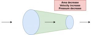
As we know that volumetric flow rate is the multiplication of velocity and cross-sectional area from which the flow is flowing. In the case of the valve, the cross-sectional area is affected. The cross-sectional area’s change is varying the velocity of flowing fluid, but the overall volume flow rate remains the same. The conservation of mass principle is satisfied. As per Bernoulli’s principle, we know that reducing cross-sectional area kinetic energy is converted into pressure energy.

flow
Area, Velocity and Pressure relationship

foe more article click here

Compressive Stress: 5 Important Facts

Compressive Stress 300x58 1

What is a compressive force?

The tensile and compressive property of the material represent the axial loads along the orthogonal axes. Loads that are stretched at the system boundaries are described as tensile loads, while those compressed at the system boundaries described as compressive loads.

The externally applied force on the body deforms the body in such a way that the body decreases in volume, and length is called compressive stress.

It is the restored strain of the body to deform when applied to external compressive load. An increase in Compressive stress to slender, long cylinders tend to undergo structural failure due to buckling of columns. When the material fails to withstand the compression, stress buckling occurs.

compressive stress
compressive stress

Compressive stress formula:

The normal force is applied to the unit area.

\sigma =\frac{F}{A}

Where,

Compressive force (F): compression force is the load required to compress the material to put the material together.

Compressive stress unit:

The SI unit of it is same as unit of the force to that of the area.

So, it is represented as N/m2 or Pa.

Dimension of Compressive stress:

Compressive stress dimension is [ML-1T-2].

Is compressive stress positive or negative?

Answer: compressive stress is negative as it is compressed since change in dimension (dL) has the opposite direction.

Are yield strength and compressive strength the same ?

Answer: No, yielding in tension and compression is not the same. Value will change as per applicability.

Compressive strength:

This is the capacity of the material to withstand the compression occur due to compressive stress. There are some materials that can withstand the only tension, some materials can withstand the only compression, and there are some materials that can withstand both tension and compression. The ultimate compressive strength is the value obtained when the material goes through its complete failure. The compression test is done the same as the tensile test. Only difference is the load used is compressive load.

Compressive strength is higher in rock and concrete.

Compressive stress of mild steel | low carbon steel:

Material that undergoes large strains before failure is ductile materials such as mild steel, aluminum and its alloys. Brittle materials, when undergoes compressive stress, the occurrence of rupture due to the sudden release of the stored energy. Whereas when the ductile material undergoes compressive stress, the material will compress, and deformation takes place without any failure.

Compressive Stress and Tensile Stress | Compressive stress vs tensile stress

  Compressive stress Tensile stress
Results of Compressive stress consequences of squeezing in the of the material. Tensile stress outcomes of stretching of the material
Push or Pull Whereas the compressive stress is the push given to body by external forces to change its shape and size. Tensile stress is the pull given to the body by external forces to change its shape and size.
Compression or elongation Compressive stress is generated from external compressive force Tensile stress is generated because of elongation force intends to stretch.
Application on Bar When bar undergoes compressive stress, strains are compressive (negative). When bar undergoes tensile stress, strains are tensile (positive).

Compressive stress strain curve

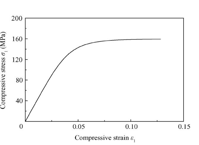
Stress-strain diagram: Compression stress

Compressive stress 1
Image credit: Wei SUN et al

The stress-strain diagram for compression is different from tension.

Under compression test, the stress-strain curve is a straight line till an elastic limit. Beyond that point, a distinct bend in the curve representing the onset of plasticity; the point shows the composite compressive yield stress, which is directly related to residual stress. The increase in residual stress increases compressive stress.

In the compression test, the linear region is an elastic region following Hooke’s law. Hence the region can be represented as,

E= Young’s modulus

In this region, the material behaves elastically and returns to its original position by the removal of stress.

Yield point:

This is the point where elasticity terminates, and plasticity region initiate. So, after yield point, material will not able to return in its actual shaped after the removal of stress.

It is found if crystalline material goes through compression, the stress-strain curve is opposite to tension applications in the elastic region. The tension and compression curves vary at larger deformations (strains) as there is compression at the compressed material, and at the tension, the material undergoes plastic deformation.

Stress-strain in tension | tensile test:

Line OA: Proportional limit

Line OA represents a proportional limit. The proportional limit is the limit till when the stress is proportionate to strain following the Hooks Law. As stress increases, the deformation of the material increases.

Point A: Elastic limit:

In this point maximum stress within a solid material has been applied. This point is called elastic limit. The material within elastic limit, will undergo deformation, and after stress removal, material will back to its actual position.

What is Elasto-plastic region?

Elasto-plastic region:

It is the region between yield point and elastic point.

Point B: Upper yield point

Plastic deformation initiates with dis-location from its crystalline structure. This displacement becomes higher after upper yield point, and it limits the movement of it,  this characteristics known known as strain hardening.

Point C: Lower yield point

This is the point after which the characteristics like strain hardening initiates. And it is observed that beyond elastic limit, the property like plastic deformation happens.

Permanent deformation:

Upper yield point:

A point at which maximum load or stress is applied to initiate plastic deformation.

The upper yield point is unstable due to crystalline dislocations movement.

Lower yield point:

The limit of min load or stress essential to preserve plastic behavior.

The lower yield point is stable as there is no movement of crystalline.

Stress is the resistance offered by the material when applied to an external load, and strain hardening is an increase in resistance slowly due to an increase of dislocations in the material.

Point D: ultimate stress point

It represents the ultimate stress point. The maximum stress can withstand the ultimate stress. After the increase of load, failure occurs.

Point E: Rupture point

It represents the breaking or rupture point. When the material undergoes rapid deformation after the ultimate stress point, it leads to failure of the material. It the maximum deformation occurred in the material.

Compressive stress example problems| Applications

  • Aerospace and Automotive Industry: Actuation tests and spring tests
  • Construction Industry: The construction industry directly depends on the compressive strength of the materials. The pillar, the roofing is built by using compressive stress.
  • Concrete pillar: In a concrete pillar, the material is squeezed together by compressive stress.
  • The material is compressed bonded, such as to avoid failure of the building. It has a sustainable amount of strained stored energy.
  • Cosmetic Industry: compaction of compact powder, eyeliners, lip balms, lipsticks, eye shadows is made by applying the compressive stress.
  • Packaging Industry: Cardboard packaging, compressed bottles, PET bottles.
  • Pharmaceutical Industry: In the pharmaceutical Industry, compressive stress is mostly used.
  • The breaking, compacting, crumbling is done in the making of tablets. The hardness and compression strength is a major part of the pharmaceutical Industry.
  • Sports industry: cricket ball, tennis ball, basketball ball are compressed to make it tougher.

How to measure compressive stress?

Compression test:

The compression test is determination of the behavior of a material under compressive load.

The Compression test is usually used for rock and concrete. Compression test gives the stress and deformation of the material. The experimental result has to validate of the theoretical findings.

Types of compression testing:

  • Flexure test
  • Spring test
  • Crushing test

Compression test is to determine the integrity and safety parameter of the material by enduring compressive stress. It also provides the safety of finished products, components, manufactured tools. It determines whether the material is fit for the purpose and manufactured accordingly.

The compression tests provide data for the following purposes:

  • To measure the batch quality
  • To understand the consistency in manufacture
  • To assist in the design procedure
  • To decrease material price
  • To guarantee international standards quality etc.

The compressive strength testing machine:

Compression testing machines comprises the measurements of material properties as Young’s modulus, ultimate compression strength, yield strength, etc., hence overall static compressive strength characteristics of materials.

The compression apparatus is configured for multiple applications. Due to machine design, it can perform tensile, cyclic, shear, flexure tests.

The compression test is operated the same as tensile testing. Only the load variation occurs in both the testing. Tensile test machines use tensile loads, whereas compression test machines use compressive loads.

Compressive strengths of various materials:

·      Compressive strength of concrete: 17Mpa-27Mpa

·      Compressive strength of steel: 25MPa

·      Granite compressive strength: 70-130MPa

·      The compressive strength of cement: 11.5 – 17.5MPa

·      The compressive yield strength of aluminum: 280MPa

What is allowable compressive stress for steel?

Answer:  The allowable stresses are commonly measured by structure codes of that metal such as steel, and aluminum. It is represented by the fraction of its yields stress (strength)

What is compressive strength of concrete at various ages?

It is the minimum compressive strength were material in standard test of 28-day-old concrete cylinder.

The concrete compressive strength measurements necessitate around 28 to 35MPa at 28 days.

Compressive Strength of Concrete:

13

Compressive stress problems:

Problem #1

A steel bar 70 mm in diameter and 3 m long is surrounded by a shell of a cast iron 7 mm thick. Calculate the compressive load for combined bar of 0.7 mm in the length of 3m. ( Esteel = 200 GPa, and Ecast iron = 100GPa.)

Solution:

δ=\frac{PL}{AE}

δ=δ cast iron=δ steel=0.7mm

δ cast iron =\frac{Pcastiron(3000)}{\frac{\pi }{4}*{<em>100 000</em>}*{84^{2}-70^{2}}} = 0.7

P cast iron = 50306.66 πN

δ steel= {\frac{Psteel(3000)}{\frac{\pi }{4}*{<em>200 000</em>}*{70^{2}}}= 0.7

P steel=57166.66πN

ΣFV=0

P= P cast iron +P steel

P=50306.66π+57166.66π

P=107473.32πN

P=337.63kN

Problem #2:

A statue weights 10KN is resting on a flat surface at the top of a 6.0m high pillar. The cross-sectional area of the tower is 0.20 m2 and it is made of granite with a mass density of 2700kg/m3. Calculate compressive stress and strain at the cross-section 3m below from the top of the tower and top segment respectively.

Solution :

The volume of the tower segment with height

H=3.0m and cross-sectional area A=0.2m2 is

V= A*H= 0.3*0.2=0.6m^3

Density ρ=2.7×10^3 kg/m3, (graphite)

Mass of tower segment

m= ρV =(2.7×10^3 *0.60m3)=1.60×10^3 kg.

The weight of the tower segment is

Wp = mg=(1.60×103*9.8)=15.68KN.

The weight of the sculpture is

Ws =10KN,

normal force 3m below the sculpture,

F⊥= wp  + ws  =(1.568+1.0)×104N=25.68KN.

Therefore, the stress is calculated by F/A

=2.568×104*0.20

=1.284×10^5Pa=128.4 kPa.

Y=4.5×10^10Pa = 4.5×10^7kPa.

So, the compressive strain calculated at that position is

Y=128.4/4.5×107

=2.85×10⁻⁶.

Problem #3:

A steel bar of changeable cross-section is endangered to axial force. Find the value of P for equilibrium.

E= 2.1*10^5MPa. L1=1000mm, L2=1500mm, L3=800mm.A1=500mm2,A2=1000mm2,A3=700mm2.

p333

From equilibrium:

{\sum Fx}= 0

+8000-10000+P-5000=0

P=7000N

Flexural Strength: 13 Interesting Facts To Know

image 10 300x86 1

Content

Flexural strength

Flexural strength (σ), also acknowledged as Modulus of rupture, or bend strength, or transverse rupture strength, is a property of material, well-defined as the material stress just before it yields in a flexure test. A sample ( circular/ rectangular cross-section) is bent until fracture or yielding using a 3 point flexural testing. The flexural strength signifies the highest stress applied at the moment of yielding.”

Flexural strength definition

flexural strength can be defined as the normal stress generated in the material because of the member’s bending or flexing in a flexure test. It is evaluated by employing a three-point bending method in which a specimen of a circular or rectangular cross-section is yielding till fractured. It is the Maximum stress experienced at the yield point by that materials.

Flexural strength formula | Flexural strength unit

Assume a rectangular specimen under a Load in 3 – point bending setup:

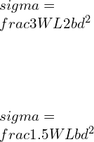
\\sigma=\\frac{3WL}{2bd^2}

Where W is the force at the point of fracture or failure

L is the distance between the supports

b is the width of the beam

d is the thickness of the beam

The unit of flexural strength is MPa, Pa etc.

Similarly, in 4 – point bending setup where the loading span is half of the support span

\\sigma=\\frac{3WL}{4bd^2}

Similarly, in 4 – point bending setup where loading span is 1/3 of the support span

\\sigma=\\frac{WL}{bd^2}

Flexural strength test

This test produces tensile stress on the specimen’s convex side and Compressive stress on the opposite side. The span to depth ratio is controlled to minimize the shear stress-induced. For most material L/d ratio is equal to 16 is considered.

In comparison with the three-point bending flexural test, Four-point bending flexural test observes No shear forces in the area between the two loading pins. Thus, The four-point bending test is most appropriate for brittle materials that cannot bear shear stresses.

Three-Point Bend test and Equations

Equivalent Point Load wL will act at the centre of the beam. i.e., at L/2

Flexural strength
FBD for Bend test

The value of the reaction at A and B can be calculated by applying Equilibrium conditions of

\\sum F_x=0, \\sum F_y=0, \\sum M_A=0

For vertical Equilibrium,

\\sum F_y=0

R_A+R_B = W.............[1]

Taking a moment about A, Clockwise moment positive, and Counter Clockwise moment is taken as negative

W*(L/2) - R_B*L = 0

R_B=\\frac{W}{2}

Putting the value of RB in [1], we get

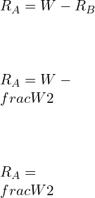
\\\\R_A=W-R_B\\\\ \\\\R_A=W-\\frac{W}{2}\\\\ \\\\R_A=\\frac{W}{2}

Following the Sign convention for S.F.D. and BMD

Shear Force at A

V_A=R_A=\\frac{W}{2}

Shear Force at C

\\\\V_C=R_A-\\frac{W}{2}\\\\ \\\\V_C=\\frac{W}{2}-\\frac{W}{2}=0

Shear Force at B

\\\\V_B=R_B=-\\frac{W}{2}

For Bending Moment Diagram, if we start calculating Bending Moment from the Left side or Left end of the beam, Clockwise Moment is taken as positive. Counter Clockwise Moment is taken as Negative.

Bending Moment at A = MA = 0

Bending Moment at C

\\\\M_C=M_A-\\frac{W}{2}*\\frac{L}{2} \\\\ \\\\M_C= 0-\\frac{WL}{4}\\\\ \\\\M_C=\\frac{-WL}{4}

Bending Moment at B = 0

In 3 – point bending setup, Flexural strength is given by

\\sigma=\\frac{3WL}{2bd^2}

Where W is the force at the point of fracture or failure

L is the distance between the supports

b is the width of the beam

d is the thickness of the beam

The unit of flexural strength is MPa, Pa etc.

Four-Point Bend test and Equations

Consider a simply supported beam with two equal Loads W acting at a distance L/3 from either end.

image 11

The value of the reaction at A and B can be calculated by applying Equilibrium conditions of

\\sum F_x=0, \\sum F_y=0, \\sum M_A=0

For vertical Equilibrium,

\\sum F_y=0

R_A+R_B = W.............[1]

Taking a moment about A, Clockwise moment positive, and Counter Clockwise moment is taken as negative

W*[L/6] - R_B*L = W[L/3]

R_B=\\frac{W}{2}

Putting the value of RB in [1], we get

\\\\R_A=W-R_B\\\\ \\\\R_A=W-\\frac{W}{2}\\\\ \\\\R_A=\\frac{W}{2}

Following the Sign convention for S.F.D. and BMD

Shear Force at A

V_A=R_A=\\frac{W}{2}

Shear Force at C

\\\\V_C=R_A-\\frac{W}{2}\\\\ \\\\V_C=\\frac{W}{2}-\\frac{W}{2}=0

Shear Force at B

\\\\V_B=R_B=-\\frac{W}{2}

For Bending Moment Diagram, if we start calculating Bending Moment from the Left side or Left end of the beam, Clockwise Moment is taken as positive. Counter Clockwise Moment is taken as Negative.

Bending Moment at A = MA = 0

Bending Moment at C = [W/2]*[L/3]………………………… [since the moment is counter-clockwise, the bending moment is coming out as negative]

Bending Moment at C =

\\\\M_C=\\frac{WL}{6}

Bending Moment at D =

M_D=\\frac{W}{2}*\\frac{2L}{3}-\\frac{W}{2}*\\frac{L}{3}

M_D=\\frac{WL}{6}

Bending Moment at B = 0

For a rectangular specimen under in 4 – point bending setup:

Similarly, when the loading span is 1/3 of the support span

\\sigma=\\frac{WL}{bd^2}

In 4 – point bending setup where the loading span is half of the support span

\\sigma=\\frac{3WL}{4bd^2}

Where W is the force at the point of fracture or failure

L is the distance between the supports

b is the width of the beam

d is the thickness of the beam

The unit of flexural strength is MPa, Pa etc.

Flexural strength vs Flexural Modulus

Flexural Modulus is a ratio of stress-induced during flexural bending to the strain during flexing deformation. It is the property or the ability of the material to resist bending. In comparison, flexural strength can be defined as the normal stress generated in the material because of the member’s bending or flexing in a flexure test. It is evaluated employing the Three-point bending method in which a specimen of a circular or rectangular cross-section is bent until fracture or yielding. It is the Maximum stress experienced by the material at the yield point.

Assume a rectangular cross-section beam made of isotropic material, W is the force applied at the middle of the beam, L is the beam’s length, b is the beam’s width, d is the thickness of the beam. δ be a deflection of the beam

For 3 – point bending setup:

Flexural Modulus can be given by

E_{bend}=\\frac{\\sigma }{\\epsilon }

E_{bend}=\\frac{WL^3 }{4bd^3\\delta }

for a simply supported beam with load at the centre, the deflection of the beam can be given by

\\delta =\\frac{WL^3}{48EI}

Flexural strength vs Tensile strength

Tensile strength is the maximum tensile stress a material can withstand under tensile loading. It is the property of the material. It is independent of the shape of the specimen. It gets affected by the thickness of the material, notches, internal crystal structures etc.

Flexural strength is not the property of the material. It is the normal stress generated in the material because of the member’s bending or flexing in a flexure test. It is dependent upon the size and shape of the specimen. The following example will explain further:

Consider a square cross-section beam and a diamond cross-section beam with sides ‘a’ and bending moment M

For a square cross-section beam

By Euler-Bernoulli’s Equation

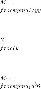
\\\\M=\\frac{\\sigma I/y}{y}\\\\ \\\\Z=\\frac{I}{y}\\\\ \\\\M_1=\\frac{\\sigma _1 a^3}{6}

For a Diamond cross-section beam

\\\\I=\\frac{bd^3}{12}*2\\\\  \\\\I=\\sqrt{2}a*[\\frac{a}{\\sqrt{2}}]^3*\\frac{2}{12}\\\\\\\\  \\\\Z=\\frac{I}{y}=\\frac{a^3}{6\\sqrt{a}}\\\\\\\\  \\\\M_2=\\frac{\\sigma _2 a^3}{6\\sqrt{a}}

But M1 = M2

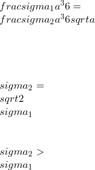
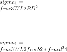
\\\\\\frac{\\sigma _1 a^3}{6}=\\frac{\\sigma _2 a^3}{6\\sqrt{a}} \\\\\\\\\\sigma _2= \\sqrt{2}\\sigma _1 \\\\\\sigma _2>\\sigma _1

Flexural strength of Concrete

Procedure for evaluating Flexure Strength of Concrete

  1. Consider any desired grade of Concrete and prepare an unreinforced specimen of dimensions 12in x 4 in x 4 in. Cure the prepared solution for 26-28 days.
  2. Before performing the Flexure test, Allow the specimen to rest in the water at 25 C for 48 hours.
  3. Immediately perform the bend test on the specimen while it is in wet condition. [Quickly after removing the specimen from the water]
  4. To indicate the roller support position, draw a reference line at 2 inches from both the edges of the specimen.
  5. The roller supports act as a simply supported beam. Gradual application of load is made on the axis of the beam.
  6. The load is increased continuously until the stress in the extreme fiber of the beam increases at the rate of 98 lb./sq. in/min.
  7. The load is continuously applied until the test specimen breaks, and the maximum load value is recorded.

In 3 – point bending setup, Flexural strength is given by

\\sigma=\\frac{3WL}{2bd^2}

Where W is the force at the point of fracture or failure

L is the distance between the supports

b is the width of the beam

d is the thickness of the beam

The unit of flexural strength is MPa, Pa etc.

Flexural strength is nearly = 0.7 times the compressive strength of the Concrete.

Flexural strength of steel

Consider a steel beam with width = 150 mm, depth = 150 mm, and length = 700 mm, applied load be 50 kN, and find the beam’s flexural stress of the beam?

In 3 – point bending setup, Flexural stress is given by

\\\\\\sigma=\\frac{3WL}{2bd^2} \\\\\\\\\\sigma=\\frac{3*50*10^3*0.7}{2*0.15*0.15^2} \\\\\\\\\\sigma=15.55\\;MPa

Flexural strength of Aluminum

The flexural strength of Aluminum grade 6061 is 299 MPa.

Flexural strength of Wood

The following table shows the flexural strength of the various type of woods.

Type of WoodFlexural strength [MPa]
Alder67.56 MPa
Ash103.42 MPa
Aspen57.91 MPa
Basswood59.98 MPa
Beech102.73 MPa
Birch, Yellow114.45 MPa
Butternut55.84 MPa
Cherry84.80 MPa
Chestnut59.29 MPa
Elm81.35 MPa
Hickory139.27 MPa

Flexural strength of a Cylinder

Consider a simply supported beam with two equal Loads W/2 acting at a distance L/3 from either end.

image 11

The value of the reaction at A and B can be calculated by applying Equilibrium conditions of

\\sum F_x=0, \\sum F_y=0, \\sum M_A=0

For vertical Equilibrium,

\\sum F_y=0

R_A+R_B = W.............[1]

Taking a moment about A, Clockwise moment positive, and Counter Clockwise moment is taken as negative

W*[L/6] - R_B*L = W[L/3]

R_B=\\frac{W}{2}

Putting the value of RB in [1], we get

\\\\R_A=W-R_B\\\\ \\\\R_A=W-\\frac{W}{2}\\\\ \\\\R_A=\\frac{W}{2}

Following the Sign convention for S.F.D. and BMD

Shear Force at A

V_A=R_A=\\frac{W}{2}

Shear Force at C

\\\\V_C=R_A-\\frac{W}{2}\\\\ \\\\V_C=\\frac{W}{2}-\\frac{W}{2}=0

Shear Force at B

\\\\V_B=R_B=-\\frac{W}{2}

For Bending Moment Diagram, if we start calculating Bending Moment from the Left side or Left end of the beam, Clockwise Moment is taken as positive. Counter Clockwise Moment is taken as Negative.

Bending Moment at A = MA = 0

Bending Moment at C = [W/2]*[L/3]………………………… [since the moment is counter-clockwise, the bending moment is coming out as negative]

Bending Moment at C =

\\\\M_C=\\frac{WL}{6}

Bending Moment at D =

M_D=\\frac{W}{2}*\\frac{2L}{3}-\\frac{W}{2}*\\frac{L}{3}

M_D=\\frac{WL}{6}

Bending Moment at B = 0

Let d = diameter of the cylindrical beam, According to Euler-Bernoulli’s Equation

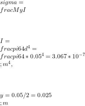
\\\\\\sigma =\\frac{My}{I}\\\\ \\\\I=\\frac{\\pi}{64}d^4, \\\\\\\\y=d/2 \\\\\\\\\\sigma =\\frac{1.697WL}{d^3}

Find the Flexural stress in the circular cylindrical beam with span of 10 m and diameter 50 mm. The beam is made of Aluminum. Compare the result with beam of square cross section with side = 50 mm. The total load applied is 70 N.

Consider a simply supported beam with two equal Loads W/2 = 35 N acting at a distance L/3 from either end.

image 12

The value of the reaction at A and B can be calculated by applying Equilibrium conditions of

\\sum F_x=0, \\sum F_y=0, \\sum M_A=0

For vertical Equilibrium,

\\sum F_y=0

R_A+R_B = 70.............[1]

Taking a moment about A, Clockwise moment positive, and Counter Clockwise moment is taken as negative

W*[L/6] - R_B*L = W[L/3]

R_B=\\frac{W}{2}=35

Putting the value of RB in [1], we get

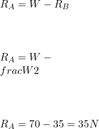
\\\\R_A=W-R_B\\\\ \\\\R_A=W-\\frac{W}{2}\\\\ \\\\R_A=70-35=35N

Following the Sign convention for S.F.D. and BMD

Shear Force at A

V_A=R_A=\\frac{W}{2}=35 N

Shear Force at C

\\\\V_C=R_A-\\frac{W}{2}\\\\ \\\\V_C=\\frac{W}{2}-\\frac{W}{2}=0

Shear Force at B

\\\\V_B=R_B=-\\frac{W}{2}=-35N

For Bending Moment Diagram, if we start calculating Bending Moment from the Left side or Left end of the beam, Clockwise Moment is taken as positive. Counter Clockwise Moment is taken as Negative.

Bending Moment at A = MA = 0

Bending Moment at C = [W/2]*[L/3]………………………… [since the moment is counter-clockwise, the bending moment is coming out as negative]

Bending Moment at C =

\\\\M_C=\\frac{WL}{6}=\\frac{70*10}{6}=125\\;Nm

Bending Moment at D =

M_D=\\frac{W}{2}*\\frac{2L}{3}-\\frac{W}{2}*\\frac{L}{3}

M_D=\\frac{WL}{6}=\\frac{70*10}{6}=125\\;Nm

Bending Moment at B = 0

Let d = diameter of the cylindrical beam, According to Euler-Bernoulli’s Equation

\\\\\\sigma =\\frac{My}{I}\\\\ \\\\I=\\frac{\\pi}{64}d^4=\\frac{\\pi}{64}*0.05^4=3.067*10^{-7}\\;m^4, \\\\\\\\y=0.05/2=0.025\\;m

\\\\\\sigma =\\frac{125*0.025}{3.067*10^{-7}}=10.189\\;MPa

For a square specimen: wiith side =d = 50mm

\\\\\\sigma =\\frac{My}{I}\\\\ \\\\\\sigma = \\frac{M(d/2)}{d^4/12} \\\\ \\\\\\sigma =\\frac{6M}{d^3} \\\\ \\\\\\sigma =\\frac{6*125}{0.05^3}\\\\ \\\\\\sigma =6 \\;MPa

Some Important FAQs.

Q.1) What does high flexural strength mean?

Ans: A material is considered to possess high flexural strength, if it bears high amount of stress in flexing or bending condition without failure in a flexure test.

Q.2) Why is flexural strength higher than tensile strength?

 Ans: During flexure test, the extreme fibers of the beam are experiencing maximum stress (top fiber experiences compressive stress and bottom fiber experiences tensile stress). If the extreme fibers are free from any defects, the flexural strength will depend upon the strength of the fibers which are yet to fail. However, when tensile load is applied to a material, all the fibers experience equal amount of stress and the material will fail upon the failure of the weakest fiber reaching its ultimate tensile strength value. Thus, In most cases flexural strength is higher than tensile strength of a material.

Q.3) What is the difference between flexure and bending?

Ans: In case of flexural bending, according to the theory of simple bending, the cross section of the plane remains plane before and after the bending. The bending moment generated acts along the entire span of the beam. no resultant force is acting perpendicular to cross section of the beam. thus, shear force along the beam is zero and any stress induced is purely due to bending effect only. In non-uniform bending, resultant force is acting perpendicular to cross section of the beam, and bending moment also varies along the span.

Q.4) Why is flexural strength important?

Ans: High flexural strength is critical for stress-bearing materials or components, when high stress is applied on the component or material.  Flexural strength also assists in determining the indications for which type of material can be used for high pressure applications. High flexural strength of the material also affects the thickness of the component’s walls. A high-strength material permits low wall thickness. A material which provides high flexural strength and high fracture toughness allows very thin wall thickness to be manufactured and is therefore ideal for minimal invasive treatment options.

Q.5) find flexural strength from stress strain curve?

Ans: Flexural strength can be defined as the highest applied stress on the stress strain curve. The energy absorption by the material beforehand failure could be estimated by area under the stress-strain curve.

Q.6) Provide the maximum flexural strength of the M30 grade of concrete?

Ans: The compressive strength of M30 grade of concrete is 30 MPa. The relation between flexural strength and compressive strength can be given by:

\\\\\\sigma_f =0.7\\sqrt{\\sigma_c}

. Thus, the maximum flexural strength of the M30 grade of concrete is,

\\\\\\sigma_f =0.7\\sqrt{30}=3.83\\;MPa

Q.7) Why is the maximum compressive strain in concrete in the flexural test 0.0035, not more or less, whereas the failure strain in concrete ranges from 0.003 to 0.005?

Ans: For theoretical calculation of maximum compressive strain in concrete in the flexural test, we consider all the assumptions of simple bending theory. During practical experimentation, various factors like defect in material, uneven cross section etc. affects the compressive strain in concrete in the flexural test. Thus, the maximum compressive strain in concrete in the flexural test 0.0035, not more or less, whereas the failure strain in concrete ranges from 0.003 to 0.005.

Q.8) If additional reinforcing bars are sited at compression side of a reinforced concrete beam. Is that enhance to the beam’s flexural strength?

Ans: Adding extra reinforcing bars provides additional strength to beam’s compressive strength, especially at the location at the positive moments occurs. The purpose of reinforcement bars is to prevent tensile failures like bending moment, since the concrete is weak in tensile loading. If the beam is high thickness along with reinforcement bars, the steel bars exclusively behave as tensile strength element while the concrete provides compression strength.

Q.9) What would happen to the flexural strength of a concrete beam if its dimensions are halved?

Ans: for a rectangular cross section beam,

In 3 – point bending setup, Flexural strength is given by

\\\\\\sigma =\\frac{3WL}{2bd^2} \\\\\\\\\\sigma =\\frac{1.5WL}{bd^2}

If the dimensions are halved
B = b/2, D = d/2

\\\\\\sigma_1 =\\frac{3WL}{2BD^2} \\\\\\\\\\sigma_1 =\\frac{3WL}{2\\frac{b}{2}*\\frac{d^2}{4}}

\\\\\\sigma_1 =\\frac{12WL}{bd^2}

\\\\\\sigma_1 >\\sigma

If the dimensions are halved, the flexural strength increased by 8 times for a rectangular cross-section material.

Q.10) What is modulus of rupture?

Ans: Flexural Modulus is a ratio of stress-induced during flexural bending to the strain during flexing deformation. It is the property or the ability of the material to resist bending.

To know about Simply Supported Beam (click here)and Cantilever beam (Click here.)

Scientific Principles: 7 Important Facts

Capture 300x277 1

Management

Management is the process of planning, organizing, leading and controlling the efforts of the members of an organization to achieve the goals of the organization. Whereas, science is the systematic theoretical knowledge derived and tested critically and finally generalized into laws, theories and principles. Introduction of scientific principles and study in the field of management is done in the field of scientific management.

Scientific management was the very early approach to introduce science into the field of engineering. Introduction of Scientific principles in the field of management gave birth to the scientific management. Scientific management is a branch of Industrial Engineering. Industrial Engineering is the branch of mechanical engineering which is focused on design, installation and improvement systems of people, information, material, energy and equipment.

As famously defined by F. W. Taylor, “Scientific management means knowing exactly what you want men to do and seeing that they do it in the best and cheapest way.”

History of Scientific Management

Management is the most significant thing that started in the Stone Age and continued until the date. In the Stone Age, management was associated with arrows’ production issues for hunting, forming wood lugs for fire, managing beasts for transportation, etc. After the invention of the wheel, the management issues got focused on the production of carts, agricultural work, etc. Still, the real era considered by historians for the management is from the period when man learned and implemented the concept of civilization successfully.

For more details Click Here!

Scientific Principles

Scientific principles are the answers of why and how of basic laws and rules of nature which are accepted by scientists. These scientific principles cannot be written in the mathematical forms. F. W. Taylor was the person who introduced these scientific principles and study in the field of management. This introduction terminated the conventional heat-and –miss and rule-of –thumb methods of management and initiated the rules of scientific investigation including research and experiments.

Scientific Principles of Sustainability

Sustainability is defined as the series of actions or processes through which human being tries to avoid the depletion of nature and natural resources. Sustainability emphasizes on pollution prevention, waste reduction and management, population stabilization, etc.

There are four main scientific principles of sustainability:

  1. Reliance on Solar Energy
  2. Biodiversity
  3. Population Control
  4. Nutrient Cycling

Every company should follow these four scientific principles while establishing and managing a company.

Principles of Scientific Management

There are four important principles of scientific management which are given by F. W. Taylor.

  • Principle #1: Science, not rule of thumb

Replacement of old rule of thumb method

  • Principle #2: Harmony, Not Discord

Co-operation between labor and management

  • Principle #3: Cooperation not individualism

Equal division of responsibility

  • Principle #4: Development of each and every person to his/her utmost efficiency and prosperity

Take care of each and every person

Development of Scientific Management

The development of scientific management is classified into five eras as follows:

  1. Handicraft Era
  2. Industrial Revolution Era
  3. Scientific Management Era
  4. Operations Research Era
  5. Computerized Systems Era
Scientific Management Theory | Management

Handicraft Era

  • This era starts with the early age of human civilization. From the 14th century to the 18th century.
  • This era was about specific groups, including carpenter, blacksmith, goldsmith, etc. so, the management was more about handicraft shops which an individual managed with a minimal volume of persons.
  • The compensation received by employees was varied according to place, time, and situation.
  • The type of work was not clearly defined, so the remuneration of the work.

Industrial Revolution Era

  • It is the era in which the factory system began to develop, and a large group of people started working together—starting from the 18th century to the 19th century.
  • Discoveries and inventions of various machines and mechanisms led to the replacement of humans by machines and the replacement of beasts by power sources. Its ultimate effect was the increase in productivity.

Productivity: It is the measure of output obtained per unit input.

  • Specialization of labor, division of labor, professional management, the introduction of public and general laws, and disconnection of ownership from management are concepts that started taking shape in this era.
  • Contributors of Era:
  • Adam Smith: Published ‘The Wealth of Nations’ in 1776, which promoted  “Specialization of Labor.”
  • James Watt: Invented ‘Steam Engine’ in 1764, which established the example of improvement of productivity using machines.
  • Henry Slator: Introduced water and steam power in the textile industry.
  • Eli Whitney: Developed the concept of “interchangeability of parts,” which led to the rapid growth of the factory system.
  • Charles Babbage: Suggested the concept of division of labor for productivity improvement.

Scientific Management Era

  • It is the era in which scientific methods were developed and implemented for process improvement. It is the early part of the 19th century.
  • Before this era, management was supposed to be more an art than science. So, the compensation method became transformed the form of time into money through analytical and mathematical solutions.
  • Development of classical management theories, development of neoclassical theory, generation of labor laws, strengthening of the workforce, quality and economy concepts’ emergence, development of participative management, development of a democratic type of leadership are the highlights of the scientific management era.
  • Contributors of Era:
  • Fredrick Winslow Taylor: Published the book ‘Principles of Scientific Management’ in 1915. He is the “Father of Scientific Management.”
  • Lillian Gilberth & F. B. Gilberth: Worked on the analysis of fundamental motions of the parts of the body at the micro-level.
  • H. L. Gantt: Developed a chart used for scheduling and wedge incentive plans.
  • Henry Ford: Developed the idea of the use of conveyors for progressive assembly.
  • F. Wilson. Harris: Proposed Economic Order Quantity (EOQ) model.
  • Walter Shewhart: developed Statistical Quality Control (SQC)
  • Henry Fayol: Developed “Principles of Organization”.

Operation Research Era

Operation Research: It involves decision-making by arriving at solutions systematically using quantitative techniques.

  • In this era, management was accepted as a profession. It is the late part of the 19th century.
  • In this era, optimization of resources has become prime important.
  • The manager’s role gained importance as the improvement in productivity and applications of optimization models became part of the manager’s job.
  • Both work allocation and work extraction were based on suitable modeling.
  • Use of the documentation process made management more systematic.
  • Decision-making became oriented on quantitative as well as qualitative aspects.
  • Development of independent demand, time phasing, material requirement planning(MRP), capacity requirement planning(CRP), just-in-time(JIT) inventory concept, enterprise resource planning(ERP), Total quality management(TQM), poka-yoke devices started in this rea.
  • Contributors of the era:
  • Joseph Orlicky, Oliver Weight, and others: Introduced the concept of independent demand, time phasing, MRP, CRP.
  • Western side: Continued with development of manufacturing resource planning(MRP-II) systems, Just-in-time(JIT) inventory concepts, Enterprise resource planning(ERP)
  • Eastern side: Witnessed the development of quality circles, Kanban, TQM(Total Quality Management), poka-yoke devices, kaizen.

Computerized Systems Era

The electronic and computerized systems developed till the date started with the development of microprocessors. Also known as chips. In this era of computerized systems. It is the early part of the 20th century.

Microprocessor: It is a processing element used in computers.

  • In this era, the process of management was computerized and automated with little or no human effort.
  • “You set a system-then it sets you” was the believed principle of the management.
  • Planning, designing, processing, transporting, information transmission, and communication are the human efforts that were replaced by machinery.
  • System approach accepted for the management.
  • Following are some of the developments which are developed in recent past years:
  • AGV-Automatic Guided Vehicle
  • AS/RS-Automatic Storage and Retrieval Systems
  • Computer Graphics
  • Computer animation
  • Automatic receipt
  • CNC- Computer/numerical controlled machinery
  • CAPP-Computer Aided Process Planning
  • CAD-Compuer Aided Design
  • CAM-Computer Aided Manufacturing
  • Computer-Aided Plant Layout Planning
  • Simulation and Modeling
  • HRM-Human Resource Management
  • Boundaryless and Virtual organization structure

Characteristics of Management

Following are the important characteristics of management:

  1. Management is scientific and mathematical.

The organizational goals are achieved by management with the help of scientific techniques and mathematical tools.

  • Management is art and tact.

Management is considered as the art of getting things done very often.

  • Management is a system of authority and responsibility.

In management, authority and responsibility go hand in hand.

  • Management is accountability

The accountability characteristic of management makes it effective and efficient.

  • Management is goal-oriented

Management is about clearly defined objectives and moving towards them successfully.

  • Management is a distinct process.

Each activity of management distinctly signifies and describes the method and style of fany functioning.

  • Management is decision-making.

A correct decision for management leads to grand success, while a wrong decision leads to failure.

  • Management is economic efficiency.

Economics is the major factor of management.

  • Management is the welfare of mankind.

To have concern for people and their welfare is very important for management.

  1. Management is an experience.

Experiences and minute records characterize the management continuity.

  1. Management is team building through coordination.

A group of people does management.

  1. Management is a profession: Management needs to apply scientific principles; therefore, it is considered a profession.
  2. Management is universal

Management is found in every act of human beings.

  1. Management is dynamic: Changing environment brings management changes.

Important Questions and Answers

What is scientific management? | Which of the following best describes scientific management?

Scientific management means knowing exactly what you want men to do and seeing that they do it in the best and cheapest way.

Who is the father of scientific management?

Fredrick Winslow Taylor is known as the father of scientific management.

Frederick Winslow Taylor
Fredrick Winslow Taylor: father of scientific management, has introduced scientific principles

What is the four Ms of management?

Men, material, machines, and methods are the four Ms of management.

With respect to the development of scientific management, Frederick Taylor’s objective was to

Scientifically determine the most efficient way to perform a task and then teaching it to people.

Which person developed the model of Economic Order Quantity?

F. Wilson Harris developed the model of EOQ.

What are the characteristics of scientific management?

Following are the important characteristics of management:

  1. Management is scientific and mathematical
  2. Management is art and tact
  3. Management is a system of authority and responsibility
  4. Management is accountability
  5. Management is goal-oriented
  6. Management is a distinct Process
  7. Management ids decision making
  8. Management is economic efficiency
  9. Management is the welfare of mankind
  10. Management is an experience
  11. Management is team building through coordination
  12. Management is a profession.
  13. Management is universal
  14. Management is dynamic

What are scientific principles?

Scientific principles are the answers of why and how of basic laws and rules of nature which are accepted by scientists. These scientific principles cannot be written in the mathematical forms. F. W. Taylor was the person who introduced these scientific principles and study in the field of management.

What are Scientific Principles of Sustainability?

Sustainability is defined as the series of actions or processes through which human being tries to avoid the depletion of nature and natural resources. Scientific Principles of Sustainability emphasizes on pollution prevention, waste reduction and management, population stabilization, etc.

There are four main scientific principles of sustainability:

1) Reliance on Solar Energy

2) Biodiversity

3) Population Control

4) Nutrient Cycling

Every company should follow these four scientific principles while establishing and managing a company

 Click Here for more such articles

    Simply Supported Beam: 9 Important Facts

    FBD 300x64 1

    Simply Supported Beam Definition

    A simply supported beam is a beam, with one end normally hinged, and other-end is having support of roller. So because of hinged support’s, restriction of displacement in (x, y) will be and because of roller support’s will be prevented the end-displacement in the y-direction and will be free to move parallel to the axis of the Beam.

    Simply Supported Beam free body diagram.

    The free-body diagram for the Beam is given below in which with point load acting at a distance ‘p’ from the left end of the Beam.

    Free Body diagram of simply supported beam
    Free Body Diagram for S.S.B

    Simply Supported Beam boundary conditions and Formula

    Evaluating Reaction forces acting on the Beam by using Equilibrium conditions 

    Fx + Fy = 0

    For vertical Equilibrium,

    Fy = RA +RB – W = 0

    Taking Moment about A equals to 0 with standard notations.

    Rb = Wp/L

    From above equation,

    RA + Wp/L = W

    Let X-X be the intersection at ‘a’ distance of x from the end point denoted by A.

    Considering standard Sign-convention, we can compute the Shear force at the point A as described in figure.

    Shear force at A,

    Va = Ra = wq/L

    Shear force at region X-X is

    Vx = RA – W = Wq/L – W

    Shear Force at B is 

    Vb = -Wp/L

    This proves that the Shear Force remains constant between points of application of Point Loads.

    Applying standard rules of Bending Moment, Clockwise Bending Moment from the Left end of the Beam is taken as +ve and Counter Clockwise Bending moment is considered as -ve respectively.

    • B.M at the point A = 0.
    • B.M at the point C = -RA p   ………………………… [since the moment is counter-clockwise, Bending Moment is coming out as negative]
    • B.M at the point C is as follows
    • B.M = -Wpq/L
    • B.M at the point B = 0.
    BMD SSB
    Shear force and bending moment diagram

    Simply supported Beam Bending moment for uniformly distributed Loading as a function of x.

    Given below is a simply-supported beam with uniformly distributed Loading applied across the complete span,

    SSB UDL 1
    S.S.B with U.D.L

    Region X-X be any region at a distance x from A.

    The resultant equivalent load acting on the Beam Due to Uniform Loading case can be elaborated by

    F = L * f

    F=fL

    Equivalent Point Load fL acting at the mid-span. i.e., at L/2

    FBD UDL

    Evaluating Reaction forces acting on the Beam by using Equilibrium conditions 

    Fx = 0 = Fy = 0

    For vertical Equilibrium,

    Fy = 0

    Ra + Rb = fL

    taking standard sign conventions, we can write

    L/2 – R = 0

    From above equation,

    RA + fl/2

    Following the standard Sign convention, shearforce at A will be.

    Va = Ra = FL/2

    Shear Force at C

    Vc = Ra – fL/2

    Shear force at region X-X is

    Vx = RA – fx = fL/2 – fx

    Shear Force at B

    Vb = -fL/2

    For Bending Moment Diagram, we can find that by taking standard notation.

    • B.M at the point A = 0.
    • B.M at the point X is
    • B.Mx = MA – Fx/2 = -fx/2
    • B.M at the point B = 0.

    Thus, the bending moment can be written as as follows

    B.Mx = fx/2

    Case I: For Simply supported Beam with a concentrated load F acting at the center of the Beam

    Below is a free body diagram for a simply supported steel beam carrying a concentrated load (F) = 90 kN acting at the Point C. Now compute slope at the point A and maximum deflection. if I = 922 centimer4, E = 210 GigaPascal, L =10 meter.

    Solutions:

    The F.B.D. Given an example is given below,

    FBD at Center
    Free Body Diagram for S.S.B with concentrated point load

    The slope at the end of the Beam is,

    dy/dx = FL/16E

    For a simply supported steel beam carrying a concentrated load at the centre, Maximum Deflection is,

    Ymax = FL/48 EI

    Ymax = 90 x 10 x 3 = 1.01m

    Case II: For Simply supported Beam having load at ‘a’ distance from support A.

    For this case acting load(F) = 90 kN at the Point C. Then compute slope at the point A and B and the maximum deflection, if I = 922 cm4, E = 210 GigaPascal, L =10 meter, a = 7 meter, b = 3 meter.

    FBD 3

    So,

    The slope at the end support A of the Beam,

    θ = Fb(L2 – b2) = 0.211

    Slope at the end support B of the Beam,

    θ = Fb (l2 – B2 ) (6 LE) = 0.276 rad

    The equation gives maximum Deflection,

    Ymax = Fb (3L – 4b) 48EI

    Slope and deflection table for standard load cases:

    image 1

    Slope and Deflection in Simply supported Beam with uniformly distributed Loading case

    Let weight W1 acting at a distance a from End A and W2 acting at a distance b from end A.

    image 3

    The U.D.L. applied over the complete Beam doesn’t require any special treatment associated with Macaulay’s brackets or Macaulay’s terms. Keep in mind that Macaulay’s terms are integrated with respect to themselves. For the above case (x-a), if it comes out negative, it must be ignored. Substituting the end conditions will yield constants’ values of integration conventionally and hence the required slopes and deflection value.

    image 6

    In This case, the U.D.L. starts at point B, the bending moment equation is modified, and the uniformly distributed load term becomes Macaulay’s Bracket terms.

    The Bending Moment equation for the above case is given below.

    EI (dy/dx) = Rax – w(x-a) – W1 (x-a) – W2 (x-b)

    Integrating we get,

    EI (dy/dx) = Ra (x2/2) – frac w(x-a) (6) – W1 (x-a) – W1 (x-b)

    Simply supported beam deflection as a function of x for distributed Loading [Triangular Loading]

    Given below is the Simply-supported Beam of span L subjected to Triangular Loading and derived the equation of slope and Bending moment utilizing the Double-integration methodology is as follows.

    image 7

    For the symmetrical Loading, every support reaction bears half of the total load and the reaction at support is wL/4 and considering moment at the point which is at a distance x from Support A is calculated as.

    M = wL/4x – wx/L – x/3 = w (12L) (3L – 4x)

    Using the diffn-equation of the curve.

    by the double Integrating we can find as.

    EI (dy/dx) = w/12L (3L x 2x 2) (-x ) + C1

    putting x = 0, y = 0 in equation [2],

    C2 = 0

    For symmetric Loading, the slope at 0.5L is zero

     Thus, slope = 0 at x = L/2,

    0 = w/12L (3L x L2 – L4 +C1)

    Substituting the constants values of C2 and C1 we get,

    EI (dy/dx) = w 12L (3L) (2) – 5wl/192

    The highest deflection is found at the center of the beam. i.e., at L/2.

    Ely = w/12L (3L x 2L x 3) (2 x 8) / l5(5 x 32) (192)

    Evaluating slope at L = 7 m and deflection from given data: I = 922 cm4 , E = 220 GPa, L =10 m, w = 15 N-m

    From the above equations: at x = 7 m,

    EI (dy/dx) = w (12L)(3L x 2x x 2) – x4 – 5wl/192

    using equation [4]

    Ely = – wl/120

    220 x 10 x 922 = 6.16 x 10⁻⁴ m

    Negative sign represents downward deflection.

    Simply supported Beam Subjected to various Loading inducing Bending Stress.

    Given below is an example of a simply supported steel beam carrying a point load and the Supports in this beam are pin supported on one end, and another is roller support. This Beam has the following given material, and loading data

    loading shown in the Figure below has F=80 kN. L = 10 m, E = 210 GPa, I = 972 cm4, d = 80 mm

    FBD 4

    Evaluating Reaction forces acting on the Beam by using Equilibrium conditions 

    Fx = 0 ; Fy = 0

    For vertical Equilibrium,

    Fy = 0 (Ra + Rb – 80000 = 0)

    Taking Moment about A, Clock wise Moment +ve, and anticlockwise moment is taken as -ve, we can calculated as.

    80000 x 4 – Rb x 10 = 0

    Rb = 32000N

    Putting the value of RB in equation [1].

    RA + 32000 = 80000

    Ra = 48000

    Let, X-X be the section of interesting at the distance of x from the endpoint A, so Shear force at A will be.

    VA = RA = 48000 N

    Shear force at region X-X is

    Vx = RA – F = Fb/L – F

    Shear Force at B is 

    Vb = -Fa/L = -32000

    This proves that the Shear Force remains constant between points of application of Point Loads.

    Applying standard rules of Bending Moment, Clockwise Bending Moment from the Left end of the Beam is taken as positive. Counter Clockwise Bending moment is taken as Negative.

    • Bending Moment at A = 0
    • Bending Moment at C = -RA a   ………………………… [since the moment is counter-clockwise, Bending Moment is coming out as negative]
    • Bending Moment at C is
    • B.M = -80000 x 4 x 6/4 = -192000 Nm
    • Bending Moment at B = 0

    Euler-Bernoulli’s Equation for Bending Moment is given by

    M/I = σy = E/R

    M = Applied B.M over the crosssection of the Beam.

    I = 2nd area moment of Inertia.

    σ = Bending Stress-induced.

    y = normal distance between the neutral axis of the Beam and the desired element.

    E = Young’s Modulus in MPa

    R = Radius of Curvature in mm

    Thus, the bending Stress in the Beam

    σb = Mmax / y = 7.90

    To know about Deflection of beam and Cantilever beam other article click below.

    Continuity Equation: 7 Important Concepts

    stream tube 300x269 1

    List of Content

    • Continuity equation
    • Continuity equation differential form
    • Continuity equation for incompressible flow
    • Continuity equation for two-dimensional coplanar flow
    • Continuity equation example
    • Question & Answers
    • MCQ
    • Conclusion

    Continuity equation

    The fluid flowing through the stream tube is assumed to the ideal fluid. There is no flow occurs across the streamline. It means that fluid enters at one end and leave at the other end there is no in-between outlet. Consider flow condition at inlet cross-section 1-1 as below,

    stream tube
    Stream tube
    Parameters Inlet section 1-1 Outlet section 2-2
    Cross-sectional area A A+dA
    Average fluid density ? ?+d?
    Mean flow velocity V V+dV

    The fluid mass which flows between this two considered sections is given by following formula,

    dm = (A V ? dt ) – ( A +  dA ) ( V+ dV ) ( ? + d? ) dt            Eq … 1

    by simplifying above equation we get ,

    dm/dt = – (A V d? + V ? dA + A ? dV)                                      Eq … 2

    As we know that steady flow means constant mass flow rate, it means here dm/dt = 0.  Now Eq. 2 turned as below,

    (A V d? + V ? dA + A ? dV) = 0                                                   Eq … 3

    Now, divide Eq. 3 with ? A V, equation will be like,

    ( d?/? ) + ( dA/A ) + ( dV/V ) = 0                                          Eq … 4

    d ( ? A V ) = 0                                                                                   Eq … 5

    ? A V = Constant                                                                             Eq … 6

    Here, the Eq. 6 makes us know that the mass of fluid passing through stream tube is constant at every section.

    Suppose the fluid is incompressible (liquid) then the density of fluid will not change at any point. It means that fluid density is constant.

    A V = Constant

    A1 V1 = A2 V2                                                                                                                           Eq … 7

    Eq. 7 represents the continuity equation for steady incompressible flow inside the stream tube. The continuity equation gives a basic understanding of area and velocity. The cross-sectional area’s change affects the velocity of flow inside the stream tube, pipe, hollow channel, etc. Here, the exciting thing is a product of velocity and cross-sectional area. This product is constant at any point in the stream tube. The velocity is inversely proportionate to the cross-section area of the stream tube or pipe.

    Continuity equation differential form

    To derive the differential form of the continuity equation, consider an object as shown in the figure. The dimensions are dx, dy, and dz. There are some assumptions for this formation. The mass of fluid is not created or destroyed, no cavity or bubbles in fluid ( continuous flow). We consider dx in the x-direction, dy in y, and dz in z directions for easiness in derivation.

    If u is the velocity of fluid flow as per shown face in the figure. It is assumed that velocity is uniform throughout the face cross-sectional area. The fluid velocity at surface 1-2-3-4 is u. now; the surface 5-6-7-8 is a dx distance far from 1-2-3-4. So, the velocity at 5-6-7-8 is given as

    u+∂u/∂x  dx
    Differential form of the continuity equation
    Differential form of the continuity equation

    As we know that there change in density by using compressible fluid. If the compressible fluid passes through an object, the density will change.

    The mass flow entering the object is given as

    Mass flow = ? A V

    Mass flow rate = ? A V dt

    The fluid entering on 1-2-3-4

    Inlet fluid = density ( area * velocity) dt

    Inlet fluid= ρ u dy dz dt

    Eq … 1

    The fluid leaving from 5-6-7-8

    Outlet fluid

    outlet fluid= [ρu+ ∂/∂x  (ρu)dx]  dy dz dtt

    Eq … 2

    Now, the difference between inlet fluid and outlet fluid is mass stayed in x direction flow.

    = ρ u dy dz dt- [ρu+ ∂/∂x  (ρu)dx]  dy dz dt
    =  - ∂/∂x  (ρu)dx  dy dz dt

    Eq … 3

    Similarly, we consider mass of fluid in y and z direction is given as below,

    = - ∂/∂y  (ρv)dx  dy dz dt

    Eq … 4

    =  - ∂/∂z  (ρw)dx  dy dz dt

    Eq … 5

    Here, the v and w are the velocities of fluid in y and z directions, respectively.

    For the mass flow of fluid in all three directions, axes are given by the addition of Eq. 3, 4, and 5. It is given as below total fluid mass,

    = -[∂/∂x  (ρu)+ ∂/∂y  (ρv)+ ∂/∂z  (ρw)]  dx  dy dz dt

    Eq … 6

    The rate of change of mass within the object is given by,

    ∂m/∂t  dt=  ∂/∂t  ( ρ ×volume )  dt=   ∂ρ/∂t  dx dy dz dt

    Eq … 7

    As per understanding of mass conservation Eq. 6 equal to Eq. 7

    -[∂/∂x  (ρu)+ ∂/∂y  (ρv)+ ∂/∂z  (ρw)]   dx  dy dz dt=  ∂ρ/∂t  dx dy dz dt

    Solving the above equation and simplifying it, we get,

    ∂ρ/∂t+∂/∂x (ρu)+ ∂/∂y  (ρv)+ ∂/∂z  (ρw)=0

    Eq … 8

    Eq. 8 is. Continuity equation for general flow. It may be steady or unsteady, compressible or incompressible.

    Continuity equation for incompressible flow

    If we consider flow is steady and incompressible. We know that in the case of steady flow ??/?t = 0. If the flow is incompressible, then density ? remains constant. So, by considering this condition, Eq. 8 can be written as,

    ∂u/∂x+ ∂v/∂y  + ∂w/∂z  =0

    Continuity equation for two-dimensional coplanar flow

    In two-dimensional flow, there are two directions x and y. So, u velocity in x-direction and v velocity in the y-direction. There is no z-direction, so velocity in the z-direction is zero. By considering these conditions, the Eq. 8 turned as below,

    ∂/∂x (ρu)+ ∂/∂y  (ρv)=0

    Compressible flow

    ∂u/∂x+ ∂v/∂y  =0 

    Incompressible flow, Density is zero

    Continuity equation example

    There is flow air through the pipe at the rate of 0.25 kg/s at an absolute pressure of 2.25 bar and temperature of 300 K. If the flow velocity is 7.5 m/s, then what will be the pipe’s minimum diameter?

    Data,

    m = 0.25 kg/s,

    P = 2.25 bar,

    T = 300 K,

    V = 7.5 m/s,

    Calculate the density of air,

    P = ? R T

    ? = P / RT

    ? = ( 2.25 * 105 )/ ( 287 * 300 ) = 2.61 kg/m3

    Mass flow rate of air,

    m = ? A V

    A = m / ? V

    A = 0.25 / ( 2.61* 7.5 ) = 0.012 m2

    As we know that area,

    A = π D2 / 4

    D= √((A*4)/π)
    D= √((0.012*4)/3.14)

    D = 0.127 m = 12.7 cm

    A jet of water in upward direction is leave nozzle  tip at the velocity of 15 m/s. The diameter of nozzle is 20 mm. suppose there is no energy loss during operation. What will be the diameter of water jet at 5 m above from the nozzle tip.

    Ans.

    First of all, imagine the system; the flow is in a vertical direction.

    Data,

    V1 = velocity of jet at the nozzle tip

    V2 = velocity of jet at 5 m above from nozzle tip

    Similarly, areas A1 and A2.

    We have general equation of motion as below,

    〖V2〗^2-〖V1〗^2=2 g s
    〖V2〗^2-〖15〗^2=2*(-9.8)*5

    V2 = 11.26 m/s

    Now , apply continuity equation,

    A1 V1 = A2 V2

    A2 = (A1 V1)/ V2

    A2=  ((π/4)* (0.02)^2* 15)/11.26=4.18* 10^-4  m^2
    π/4*〖d2〗^2  =4.18* 10^-4 m^2

    Diameter = 0.023 m = 23 mm

    Questions & Answers

    What is the difference between the continuity equation and the Navier Stokes equation?

    Fluids, by definition, can flow but it is fundamentally incompressible in nature. The continuity equation is a consequence of fact that what goes into a pipe/ hose must also release out. So, in the end, the area times the velocity at the end of a pipe/hose must remain constant.

    In a necessary consequence if the area of the pipe/hose decreases, the fluid’s velocity must also increase to keep the flowrate constant.

    While the Navier-Stokes equation describes the relations in between velocity, pressure, temperatures, and density of a moving fluid. This equation usually coupled with various differential equation forms. Usually, it’s pretty complex to solve analytically.

    What is the continuity equation based on?

    The equation of continuity says that the volume of fluid entering into the pipe of any cross-section should be equal to the volume of fluid leaving the other side of the cross-sectional area, which means the rate of flow rate should be constant and should follow the relation-

    Suppose the fluid is incompressible (liquid), then the fluid density will not change at any point. It means that fluid density is constant.

    A V = Constant

    Flow rate = A1 V1 = A2 V2

    What is the continuity equation used for?

    Continuity equation has many applications in the field of Hydrodynamics, Aerodynamics, Electromagnetism, Quantum Mechanics. It is an important concept for the fundamental rule of Bernoulli’s Principle, it is indirectly involved in the Aerodynamics principle and applications.

    The equation of continuity expresses a local conservation law depending on the context. It is merely a mathematical statement that is subtle yet very powerful concerning the local conservation of specific quantities.

    Does the equation of continuity hold for supersonic flow?

    Yes, It can be used for supersonic flow. It can be used for other flows like hypersonic, supersonic, and subsonic. The difference is that you have to use the conservative form of the equation.

    What is the three-dimensional form of the continuity equation for steady incompressible flow?

    If we consider flow is steady and incompressible. We know that in the case of steady flow ??/?t = 0. If the flow is incompressible, then density ? remains constant. So, by considering this condition, Eq. 8 can be written as,

     ∂u/∂x+ ∂v/∂y  + ∂w/∂z  =0

    What is the 3D form of the continuity equation for steady compressible and incompressible flow?

    In two-dimensional flow, there are two directions x and y. So, u velocity in x-direction and v velocity in the y-direction. There is no z-direction, so velocity in the z-direction is zero. By considering these conditions, the Eq. 8 turned as below,

    ∂/∂x (ρu)+ ∂/∂y  (ρv)=0
     ∂u/∂x+ ∂v/∂y  =0

    Multiple Choice Questions

    Which one of the following is a form of continuity equation?

    1. v1 A1 = v2 A2
    2. v1 t1 = v2 t2
    3. ΔV / t
    4. v1 / A1 = v2 / A2

    What does the continuity equation give the concept about the movement of an ideal fluid?

    1. As the cross-sectional area increases, the speed increases.
    2. As the cross-sectional area decreases, the speed increases.
    3. As the cross-sectional area decreases, the speed decreases.
    4. As the cross-sectional area increases, the volume decreases.
    5. As the volume increases, the speed decreases.

    The equation of continuity is based on the principle of

    a) conservation of mass

    b) conservation of momentum

    c) conservation of energy

    d) conservation of force

    Two similar pipe diameters of d converge to obtain a pipe of diameter D. What can be the observation between d and D?. The velocity of flow in the new pipe will be double that in each of the two pipes?

    a) D = d

    b) D = 2d

    c) D = 3d

    d) D = 4d

    The pipes of different diameters d1 and d2 converge to obtain a pipe of diameter 2d. If the liquid velocity in both pipes is v1 and v2, what will be the flow velocity in the new pipe?

    a) v1 + v2

    b) v1 + v2/2

    c) v1 + v2/4

    d) 2(v1 + v2)

    Conclusion

    This article includes continuity equation derivations with their different form and conditions. Basic examples and questions are given for a better understanding of the concept of the continuity equation.

    For more articles with related topics, click here

    Read more Scientific Principles.

    Cantilever Beam: 11 Facts You Should Know

    Slide2 1 300x80 1

    Contents: Cantilever Beam

    • Cantilever Beam Definition
    • Cantilever Beam Free Body diagram
    • Cantilever Beam Boundary conditions
    • Determine the internal shear and Bending moment in the cantilevered beam as a function of x
    • Finding Shear force and Bending Moment acting at a distance of 2 m from the free end on a Cantilever beam with Uniformly Distributed load (U.D.L.)
    • The equation of the deflection curve for a cantilever beam with Uniformly Distributed Loading
    • Cantilever beam Stiffness and vibration
    • Cantilever beam bending due to pure bending moment inducing Bending Stress
    • Finding Cantilever Bending Stress induced due to Uniformly Distributed load (U.D.L.)
    • Question and Answer on Cantilever beam

    Cantilever Beam Definition

    “A cantilever is a rigid structural element that extends horizontally and is supported at only one end. Typically, it extends from a flat vertical surface such as a wall, to which it must be firmly attached. Like other structural elements, a cantilever can be formed as a beam, plate, truss, or slab.”

    https://en.wikipedia.org/wiki/Cantilever

    A cantilever beam is a beam whose one end is fixed, and another end is free. The fixed support prevents the displacement and rotational motion of the beam at that end. Cantilever beam permits the overhanging feature without any additional support. When the load is applied to the free end of the beam, the cantilever transmits that load to the support where it applies the shear force [V] and the bending Moment [B.M.] at the fixed end.

    Cantilever beam free body diagram

    Consider a cantilever beam with point load acting on the free end of the beam.

    The Free body diagram for the cantilever beam is drawn below:

    Slide2 1
    Free body diagram

    Cantilever beam boundary conditions

    The reaction Forces and moment at A can be calculated by applying Equilibrium conditions of

    \\sum F_y=0, \\sum F_x=0 ,\\sum M_A=0

    For horizontal Equilibrium

    \\sum F_x=0
    R_{HA}=0

    For vertical Equilibrium

    \\sum F_y=0
    \\\\R_{VA}-W=0
    \\\\R_{VA}=W

    Taking Moment about A, Clockwise moment positive and Counter Clockwise moment is taken as negative

    WL-M_A=0
    M_A=WL

    Determine the internal shear and Bending moment in the cantilevered beam as a function of x

    Consider the Cantilever beam with Uniformly distributed loading shown in the Figure below.

    Cantilever Beam with Uniformly distributed load
    Cantilever Beam with U.D.L

    The resultant load acting on the Beam Due to U.D.L. can be given by

    W = Area of a rectangle

    W = L * w

    W=wL

    Equivalent Point Load wL will act at the centre of the beam. i.e., at L/2

    Free Body Diagram of the Beam becomes

    Presentation1

    The value of the reaction at A can be calculated by applying Equilibrium conditions

    \\sum F_y=0, \\sum F_x=0 ,\\sum M_A=0

    For horizontal Equilibrium

    \\sum F_x=0
    \\\\R_{HA}=0

    For vertical Equilibrium

    \\sum F_y=0
    \\\\R_{VA}-wL=0
    \\\\R_{VA}=wL

    Taking Moment about A, Clockwise moment positive and Counter Clockwise moment is taken as negative

    wL*\\frac{L}{2}-M_A=0
    \\\\M_A=\\frac{wL^2}{2}

    Let X-X be the section of interest at a distance of x from a free end

    According to the Sign convention discussed earlier, if we start calculating Shear Force from the Left side or Left end of the beam, Upward acting force is taken as Positive, and Downward acting Force is taken as Negative.

    Shear force at A is 

    S.F_A=R_{VA}=wL

    at region X-X is

    S.F_x=R_{VA}-w[L-x]
    \\\\S.F_x=wL-wL+wx=wx

    Shear force at B is

    S.F=R_{VA}-wL
    \\\\S.F_B=wL-wL=0

    The shear Force values at A and B states that the Shear force varies linearly from fixed end to free end.

    For BMD , if we start calculating Bending Moment from the Left side or Left end of the beam, Clockwise Moment is taken as Positive and Counter-Clockwise Moment is taken as Negative.

    B.M at A

    B.M_A=M_A=\\frac{wL^2}{2}

    B.M at X

    B.M_x=M_A-w[L-x]
    \\\\B.M_x=\\frac{wL^2}{2}-\\frac{w(L-x)^2}{2}
    
    \\\\B.M_x=wx(L-\\frac{x}{2})

    B.M at B

    B.M_B=M_A-\\frac{wL^2}{2}
    
    \\\\B.M_B=\\frac{wL^2}{2}-\\frac{wL^2}{2}=0
    Slide5 1
    S.F.D and B.M.D

    Finding Shear force and Bending Moment acting at a distance of 2 m from the free end on a Cantilever beam with Uniformly Distributed load (U.D.L.)

    Consider the Cantilever beam with uniformly distributed loading shown in the Figure below. w = 20 N/m only. L = 10 m, x = 2 m

    Slide6

    The resultant load acting on the Beam Due to U.D.L. can be given by

    W = Area of a rectangle

    W = 20*10

    W=200 N

    Equivalent Point Load wL will act at the centre of the beam. i.e., at L/2

    Free Body Diagram of the Beam becomes,

    Slide7

    The value of the reaction at A can be calculated by applying Equilibrium conditions

    \\sum F_y=0, \\sum F_x=0 ,\\sum M_A=0

    For horizontal Equilibrium

    \\sum F_x=0
    \\\\R_{HA}=0

    For vertical Equilibrium

    \\sum F_y=0
    \\\\R_{VA}-wL=0
    \\\\R_{VA}=200 N

    Taking Moment about A, Clockwise moment positive and Counter Clockwise moment is taken as negative

    200*\\frac{10}{2}-M_A=0
    \\\\M_A=1000 \\;N-m

    Let X-X be the section of interest at a distance of x from a free end

    According to the Sign convention discussed earlier, if we start calculating Shear Force from the Left side or Left end of the beam, Upward acting force is taken as Positive, and Downward acting Force is taken as Negative.

    Shear force at A is 

    S.F_A=R_{VA}=wL
    \\\\S.F_A=200 N

    at region X-X is

    S.F_x=R_{VA}-w[L-x]
    \\\\S.F_x=wL-wL+wx=wx

    for x = 2 m

    \\\\S.F_x=wx=20*2=40\\;N

    Shear force at B is

    S.F=R_{VA}-wL
    \\\\S.F_B=wL-wL=0

    The shear Force values at A and B states that the Shear force varies linearly from fixed end to free end.

    For BMD , if we start calculating Bending Moment from the Left side or Left end of the beam, Clockwise Moment is taken as Positive and Counter-Clockwise Moment is taken as Negative.

    B.M at A

    B.M_A=M_A
    B.M_A=1000\\;N.m

    B.M at X

    B.M_x=M_A-w[L-x]
    
    \\\\B.M_x=\\frac{wL^2}{2}-\\frac{w(L-x)^2}{2}=wx[L-\\frac{x}{2}]
    \\\\B.M_x=20*2*[10-\\frac{2}{2}]=360\\;N.m

    B.M at B

    B.M_B=M_A-\\frac{wL^2}{2}=1000-\\frac{20*10^2}{2}=0
    
    Slide8

    The equation of the deflection curve for a cantilever beam with Uniformly Distributed Loading

    Consider the Cantilever beam of length L shown in the Figure below with Uniformly distributed load.  We will derive the equation for slope and deflection for this beam using the Double integration method.

    Slide3 1

    The bending moment acting at the distance x from the left end can be obtained as:

    M=-wx* \\frac{x}{2}

    Using the differential equation of the curve,

    \\frac{d^2y}{dx^2}=M = \\frac{-wx^2}{2}

    Integrating once we get,

    EI \\frac{dy}{dx}= \\frac{-wx^3}{6}+C_1………..[1]

    Integrating equation [1] we get,

    EIy= \\frac{-wx^4}{24}+C_1 x+C_2……..[2]

    The constants of integrations can be obtained by using the boundary conditions,

    At x = L, dy/dx = 0; since support at A resists motions. Thus, from equation [1], we get,

    C_1=\\frac{wL^3}{6}

    At x = L, y = 0, No deflection at the support or fixed end A Thus, from equation [2], we get,

    0= \\frac{-wL^4}{24}+\\frac{wL^3}{6} *L+C_2
    C_2= \\frac{-wL^4}{8}

    Substituting the constant’s value in [1] and [2] we get new sets of equation as

    EI \\frac{dy}{dx}= \\frac{-wx^3}{6}+\\frac{wL^3}{6}………..[3]
    EIy= \\frac{-wx^4}{24}+\\frac{wL^3}{6} -\\frac{wL^4}{8}……..[4]

    Evaluate slope at x = 12 m and maximum deflection from given data: I = 722 cm4 , E = 210 GPa, L =20 m, w = 20 N-m

    From the above equations: at x = 12 m,

    EI \\frac{dy}{dx}= \\frac{-wx^3}{6}+\\frac{wL^3}{6}
    210*10^9*722*10^{-8}* \\frac{dy}{dx}= \\frac{-20*12^3}{6}+\\frac{20*20^3}{6}
    \\frac{dy}{dx}=0.01378 \\;radians

    From equation [4]

    EIy= \\frac{-wx^4}{24}+\\frac{wL^3}{6} -\\frac{wL^4}{8}
    210*10^9*722*10^{-8}*y= \\frac{-20*12^4}{24}+\\frac{20*20^3}{6} -\\frac{20*20^4}{8}
    y=-0.064 \\;m

    Cantilever beam Stiffness and vibration

    Stiffness can be defined as the resistance to bending deflection or deformation to bending moment. The ratio of the maximum load applied to the maximum deflection of a beam can be called the stiffness of the beam.

    For a cantilever beam with a Force W at the free end, the maximum deflection is given by

    δ=\\frac{WL^3}{3EI}

    Where W = applied load, L = length of the beam, E = young’s Modulus, I = the second Moment of Inertia

    Stiffness is given by,

    k=W/δ
    \\\\k=W/\\frac{WL^3}{3EI}
    
    \\\\k=\\frac{3EI}{L^3} 

    The natural frequency can be defined as the frequency at which a system tends to vibrate in the absence of any driving or resisting force.

    ω_n=\\sqrt{k/m}
    \\\\ω_n=\\sqrt{\\frac{3EI}{L^3m} }
    

    Where m = mass of the beam.

    Cantilever beam bending due to pure bending Moment inducing Bending Stress

    When a member is subjected to equal and opposite couples in the member’s plane, it is defined as pure bending. In pure bending Shear force acting on the beam is zero.

    Assumptions: Material is Homogenous

    Hook’s Law is applicable

    Member is prismatic

    A couple is applied in the plane of the member

    No warping of the cross-section of the beam takes place after bending

    Strain profile must be linear from the neutral axis

    The stress distribution is linear from the neutral axis to the top and bottom fibres of the beam.

    Euler-Bernoulli’s Equation for Bending Moment is given by

    \\frac{M}{I}=\\frac{\\sigma_b}{y}=\\frac{E}{R}

    M = Applied bending moment over the cross-section of the beam.

    I = Second area moment of Inertia

    σ = Bending Stress-induced in the member

    y = Vertical distance between the neutral axis of the beam and the desired fibre or element in mm

    E = Young’s Modulus in MPa

    R = Radius of Curvature in mm

    Bending Stress for cantilever beam with diameter d, and applied load W can be given as,

    Slide1 3

    Bending Stress will be acting at the fixed support of the beam

    The moment applied M = W.L.

    Second Area moment of Inertia

    I=\\frac{\\pi}{64}d^4

    The vertical distance between the neutral axis of the beam and the desired fiber or element

    y=d/2

    Bending Stress is given as

    σ=\\frac{My}{I}
    
    \\\\σ=\\frac{32WL}{\\pi d^3}

    Finding Bending Stress acting on Cantilever beam with Uniformly Distributed load (U.D.L.)

    Consider A Cantilever beam with Uniformly distributed loading shown in the Figure below has I = 722 cm4 , E = 210 GPa, L =20 m, w = 20 N-m

    Slide7 1

    The reaction Forces and moment at A can be calculated by applying Equilibrium conditions of

    \\sum F_y=0, \\sum F_x=0 ,\\sum M_A=0

    For horizontal Equilibrium

    \\sum F_x=0
    \\\\R_{HA}=0

    For vertical Equilibrium

    \\sum F_y=0
    \\\\R_{VA}-wL=0
    \\\\R_{VA}=200 N

    Taking Moment about A, Clockwise moment positive and Counter Clockwise moment is taken as negative

    200*\\frac{10}{2}-M_A=0
    \\\\M_A=1000 \\;N-m

    Bending Stress

    σ=\\frac{My}{I}
    
    σ=\\frac{1000*50*10^{-3}}{2*722*10^{-8}}
    
    σ=3.238\\;MPa
    

    Question and Answer on Cantilever beam

    Q.1 What is the ratio of Maximum load applied to maximum deflection of a beam called?

    Ans: Stiffness can be defined as the resistance to bending deflection or deformation to bending moment. The ratio of the maximum load applied to the maximum deflection of a beam can be called the stiffness of the beam.

    Q.2 Define a cantilever beam?

    Ans: A cantilever beam is a beam whose one end is fixed, and the other end is free. The fixed support prevents the displacement and rotational motion of the beam at that end. Cantilever beam permits the overhanging feature without any additional support. When the load is applied to the free end of the beam, the cantilever transmits that load to the support where it applies the shear force [V] and the bending Moment [B.M.] towards the fixed end.

    Q.3 A cantilever beam is subjected to uniformly distributed load over the length of the beam, what will be the shape of Shear Force and Bending Moment diagram?

    Ans: For a cantilever beam subjected to uniformly distributed load over the beam’s length, the Shear force diagram’s shape will be a linear curve and Bending Moment diagram will be a Parabolic curve.

    Q.4 A cantilever is subjected to uniformly Varying load over the length of the beam starting at zero from a free end, what will be the shape of Shear Force and Bending Moment diagram?

    Ans: For a cantilever beam subjected to uniformly varying load over the beam’s length, the Shear force diagram’s shape will be Parabolic curve and Bending Moment diagram will be a cubic or third-degree curve.

    Q.5 Where do tension and compression act in bending of cantilever beams?

    Ans: For a cantilever beam of a given span, the maximum bending stress will be at the beam’s Fixed end. For downward netload, maximum tensile bending stress is acted on top of cross-section, and max compressive Stress is acted on the bottom fibre of the beam.

    Q.6 A cantilever is subjected to Moment (M) over the length of the beam, what will be the Shear force and Bending Moment?

    Ans: For a cantilever beam subjected to moment M over the beam’s length, the Shear force will be zero, since no external bending force will be acting on the beam and Bending moment will remain constant for the entire length of the beam.

    To know about Strength of material(click here)and Bending Moment Diagram Click here