Pipe Elbow Dimensions:Exhaustive Problems Solution and Facts

330px Mitre joint pipe 300x247 1

To change the direction of piping, pipe elbows are used. It is important to find pipe elbow dimensions for making a turn of desired radius.

This article discusses about different types of elbows and formulae to calculate their dimensions.

What is elbow in piping?

The path of piping is not always straight, it makes a turn at the end as required.


Elbows are the connectors between two pipes that are inclined at some angle. Elbow contains two openings at a specific angle where the pipes are fixed. Elbows usually come in 90 degrees, 45 degrees or 22.5 degrees.

What is the use of elbow in pipe fitting?

When there is a need to change the direction of fluid flow, the piping system needs to be bent.

This bent cannot be achieved directly by bending the PVC pipe as it is brittle in nature. An elbow is used which connects two straight pipes in angle. This way the direction of piping system is changed and hence the direction of fluid flow.

How do you calculate pipe length elbow?

To calculate the length of the pipe elbow, we need the distance between the ends of two pipes that need to be connected and the angle subtended by elbow.

Lets take an example of 90 degree pipe elbow for which pipe end distance (radius of elbow) is 300 mm.

Circumference of circle is given by-

Circumference = 2πr

90 degree elbow covers 0.25x circumference of circle. Hence, the length of pipe elbow- 0.25 x circumference of circle with radius 300mm.

What is the formula of 90 degree elbow?

Take off is defined as the length of material removed to make the pipe and fitting of a specified length.

The formula for 90 degree elbow is given below-

A = tan(45) x 1.5D X 24.5

Where,

D is diameter of elbow in inch

A is elbow center take off

What is the length of a 90 degrees elbow?

90 degrees elbow makes one quarter of a full circle. To find the length of 90 degrees elbow, we find the circumference of circle and then multiply it by 0.25.

The circumference of circle is given by the formula:

Circumference = 2πr

Hence the length of elbow becomes- 0.25 x circumference

What is the radius of pipe elbow?

On the basis of length of radius, elbows are classified into types- long radius elbow and short radius elbow. 

Radius of curvature is around 1.5 times the nominal diameter of the pipe for long radius elbows. On the other hand, radius of curvature is equal to the nominal diameter of the pipe for short radius elbows.

Short radius elbows are used where space limitation is there and abrupt change is required.

How do you measure 45 degrees elbow length?

A 45 degrees elbow makes 1/8 th of a full circle. Hence, the length of 45 degrees elbow will be equal to 0.125 times the circumference of circle.

If the radius of curvature is r, then circumference of circle is given by-

Circumference = 2πr

Where, the length of 45 degrees elbow will be

L = 0.125 x 2 x π x r

What is the formula of 45 degree elbow?

We have discussed above the formula for calculating take off for 90 degrees elbow.

For calculating take off length for 45 degrees elbow, we use the formula given below-

A = tan(22.5) x 1.5 D x 24.5

Where,

D is diameter of elbow in inch

A is elbow center take off

How many types of pipe elbows are there?

The pipe elbow can be classified on the basis of angle and the length of radius.

On the basis of angle subtended, the pipe elbows are classified as-

  • 90 degrees elbow
  • 45 degrees elbow
  • 180 degrees elbow

For special purposes, 60 degrees and 120 degrees elbows are also made.

On the basis of length of radius, elbows are classified as-

  • Long radius elbow- The radius of curvature is 1.5 times the nominal diameter of the pipe.
  • Short radius elbow- The radius of curvature is equal to the nominal diameter of the pipe, short radius elbows are used in places where space is very less.

How do I straight pipe my elbow?

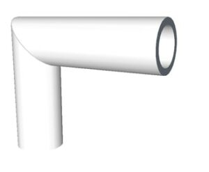
Miter bend is a type of bend in which the pipes are first cut at various angles and then joint together from ends to make an elbow in the piping.

A typical 90 degrees miter bend is made by joining ends of two pipes each cut at 45 degrees. These pipes are usually welded to each other.
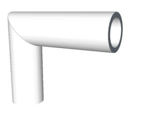
Pipe elbow dimensions
Image: Miter joint

Image credits: Wikipedia

What is the take off for a 6 inch 90 degrees elbow?

The formula for 90 degrees elbow is-

A = tan(45) x 1.5 D x 24.5

Where,

D is diameter of elbow in inch

A is elbow center take off

Substituting D as 6, we get elbow center take off, A as 220.5

How do you join different size PVC pipes?

We can use reducers and bushings for connecting PVC pipes of different sizes.

  • For connecting a larger diameter pipe with smaller diameter pipe, we use a reducer to make a coupling.
  • For connecting a larger fitting to a smaller pipe, we use a reducing bushing.

The reducers and bushings come in various diameters.
Saturated VS Superheated Steam: Detailed Analysis and FAQs

Mollier 300x191 1

Steam can occur as in various forms depending on temperature and pressure. This article discusses on the topic saturated vs superheated steam.

Saturated steam is the steam in which water exists in both liquid and gaseous state whereas Superheated steam is the steam whose temperature is above vaporization point.

What is saturated steam?

As discussed above, saturated steam is the condition where gaseous and liquid water co-exist. The temperature at which this happens is called as saturation temperature and pressure at which this happens is called saturation pressure.

When we say that both phases of water co exist, it means that the liquid water is in a transition state. The liquid water starts getting converted to gaseous state. If we decrease the temperature, the gas particles will condense to become liquid, if we heat it further then the saturated steam become superheated steam.

Effect on saturation temperature with changing pressure

When we change pressure of the system, the saturation temperature also changes. At lower pressure, the saturation temperature is also less. For example, if we go to higher altitudes where the pressure is low, water will start boiling sooner.

The enthalpy of steam first increases with increasing pressure, after some point it starts decreasing with pressure. This change can be represented on Mollier diagram (discussed in further sections).

What is superheated steam?

As discussed above, superheated steam occurs when temperature of the steam is raised above the vaporization point. In this state of steam, all the liquid particles turn to gas.

The enthalpy of superheated steam is much higher than saturated steam for a given pressure and temperature. It can be shown on Mollier diagram. Mollier diagram is discussed in detail in later section of this article.

Enthalpy-Entropy diagram/ Mollier diagram

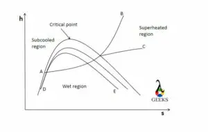
The characteristics of steam can be plotted on h-s diagram also called as Mollier diagram named after the Richard Mollier who plotted the diagram in 1904.

The diagram consists a set of curves that represents different characteristics of steam. The details about curves are given below-

  • Horizontal axis represents entropy (s).
  • Vertical axis represents enthalpy (h).
  • Line A-B represents constant pressure line.
  • Line A-C represents constant temperature line.
  • The dome represents saturated vapour line.
  • Internal lines (D-E) making a similar dome are constant dry fraction lines.
  • The tip of saturated vapour curve represents critical point.
  • Region on the left side of saturated vapour curve is sub cooled region.
  • Region inside the saturated vapour curve is saturated region.
  • Region on the right side of saturated vapour curve represents superheated region.

Note that constant pressure line and constant temperature line are parallel inside the saturated vapour dome.

Saturated Vs superheated steam
Image: Mollier diagram

Saturated and superheat steam conditions

Using the Mollier diagram we can find out the conditions required for saturated and superheat regions.

First we find the condition for saturated steam. For saturated steam condition, the dryness fraction of the steam should be between 0 and 1. For superheated steam, the dryness fraction of the steam should be greater than 1.

In a nutshell,

For saturated steam at given saturation temperature and pressure- 0<x<1

For superheated steam at a given temperature and pressure- x>1

Where x denotes the dryness fraction.

What is dryness fraction?

Saturated steam is a mixture of both water and steam. To find the amount of steam present in the mixture, the term dryness fraction is used.

This term helps in giving an accurate data of steam characteristics. Without this term, characteristics of water would also come into play. Dryness fraction is the amount of dry steam present in the water-steam mixture.

Mathematically,

x = mdrystream/mmixture

This term helps in finding the actual enthalpy of steam and determines the quality of steam. Quality in terms of quantity of steam in the mixture. 100% quality implies the dryness fraction is 1 and the mixture contains only dry steam.

Why is the heat transfer co efficient of saturated steam higher than a superheated steam?

Saturated steam is better at heat transfer than superheated steam.

Superheated steam is a bad conductor of heat and has low thermal conductivity which means it will have low heat transfer co efficient. Saturated steam has better thermal conductivity due to liquid and gas particles mixture. Liquid water being a good conductor of heat, increases the overall heat transfer co efficient of saturated steam.

Due to above reasons, saturated steam has higher heat transfer co efficient than superheated steam.

Turbine Efficiency:Complete Insights and FAQs

turbine efficiency 0

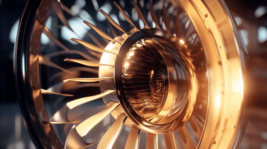
The efficiency of any device is a measure of its performance

The turbine efficiency is expressed as the ratio of useful work energy output to the input energy.

There are mainly two types of a steam turbines. One is an impulse turbine, and another is a reaction turbine. The efficiency of both turbines is different, and it depends upon its action of work.

There are many factors on which the turbine efficiency depends. It can be blade angle, guide vanes angle at the inlet to the turbine, velocity of steam, etc.

turbine efficiency formula

We can know and compare the performance of turbine with turbine efficiency

em%3E%7B3%7D h %7B4%7D%7D%7Bh %7B3%7D h %7B4s%7D%7D%7D%7D

Here,

h3 – enthalpy on point 3

h4 – the enthalpy point 4 (actual turbine)

h4s – the enthalpy point 4s (isentropic turbine)

The isentropic efficiency of the turbine can give us an ideal performance of the turbine. The heat rejected to the surrounding is to be assumed as zero. The isentropic efficiency can be calculated by the ratio of actual work to ideal work.

The ideal turbine is a device that works with 100 % efficiency. It means that all the input energy is converted into useful work. This type of turbine is impossible in the real world. There are always some losses present in the turbine in the form of heat and friction.

turbine efficiency
T – S Diagram of Rankine Cycle credit Wikipedia

turbine efficiency curve

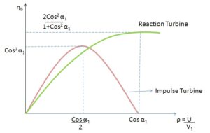
the turbine efficiency curve for impulse and reaction turbine is shown below

turbine efficiency
Turbine efficiency curve for impulse and reaction turbine credit Wikipedia

What is stage efficiency of a turbine

The stage efficiency or gross efficiency of the turbine is related to the stages of blades.

The stage efficiency is the ratio work supplied on the blade by per kg of steam to the energy given per stage (per kg of steam)

Stage efficiency can also be expressed as the multiplication of nozzle efficiency and blade efficiency.

In an impulse turbine, there are stages of blades and nozzle set. The stage efficiency is the providing performance of stage by work done in the stages and enthalpy dropping in nozzles.

gif

how to improve turbine efficiency

The turbine efficiency can be improved by some factors discussed below

It can be enhanced by the superior blade design, Coatings of exhaust blade and geometry

Why turbine has more efficiency than pump

The pump and turbine efficiency can be compared based on fluid handling

The pressure losses in the pumps are higher than in the turbine. This loss can be reduced by making the boundary layer thin in the turbine.

The working fluid in the turbine is expanding from the inlet. At the inlet, the static pressure and the velocity rise continuously. The rising in the kinetic energy of the fluid leads to a decrease in losses. The thin boundary layer can decrease the losses of power.

In the pump, the boundary layer thickness of fluid is more due to deceleration to raise static pressure. This increase in thickness leads to an increase in the losses in the pump.

average turbine efficiency

The average efficiency of the turbine varies between some range depending on size and stage.

The average efficiency of a single-stage turbine is 40 % whereas, the efficiency for the multi-stage turbine is 65 – 90%.

The efficiency in the multistage turbine is high due to the moderate to high pressure ratio. The steam will get expanding through various stages, which is beneficial to efficiency.

What is the ideal efficiency range for practical turbines

The ideal efficiency range of a practical turbine is dependent on various losses.

The overall plant thermal efficiency for the steam turbine is 42- 45%.

The power plant running on the superheated boiler is working with fossil fuels like coal. There are many heat losses present in a practical turbine. Due to thermal losses, the efficiency of the practical turbine is low.

turbine vs piston efficiency

The turbine and piston engine can be compared for aircraft

The piston engine is more efficient compared to the turbine due to less specific fuel consumption.

The turbine is light in weight compared to piston engines. The weight of piston engines is more due to bore, turbocharger, etc. To reduce the unbalancing in an airplane, a long nose is provided.

What is the maximum efficiency of a generator

The generator is a device that provides electrical energy at the expense of mechanical energy.

If the losses are proportional to the square of load current, then the generator’s efficiency is maximum.

The generator efficiency can be stated as the ratio of output electrical power to input mechanical power.

The efficiency of the dc generator can be maximum if the variable and constant losses are the same. The variable losses are armature losses, and the constant losses are field circuit losses and rotational losses.

Saturated Liquid Line: Need to Know Critical Facts

download 2

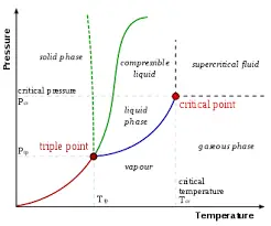
If we consider the phase diagram of a pure substance, the Saturated Liquid Line and Saturated Vapor Line divide the whole phase diagram into three regions.

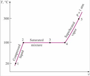
A pure substance undergoes state changes as per the variation in temperature, pressure, and volume of the substance. The solid line which separates compressed or sub-cooled liquid from the saturated mixture is known as Saturated Liquid Line.

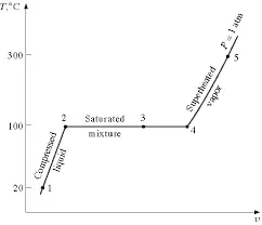
A simple saturated liquid line for water at constant pressure is shown in the Temperature-Volume diagram as below:

Image Credit: T-v diagram for the heating process of water at constant pressure https://www.unipamplona.edu.co/unipamplona/portalIG/home_34/recursos/01general/17012012/unidad_iii_termo_i.pdf

The saturated liquid line denotes the phase change of a substance from liquid to vapor. Below the saturated liquid line, the substance is in pure liquid form, and above it is in partial vapor form till enough heat is added to convert it to 100% vapor.

A substance occupies a higher specific volume above its saturated liquid line due to vaporization.

saturated liquid line

What is a Saturation Line

The saturation line is a point in the Temperature Pressure equilibrium diagram beyond which a substance or component in a system is either changing from liquid to vapor or vapor to liquid.

In general parlance, the Saturation line is synonymous with the concepts of Boiling and Condensation. In fact, both boiling and condensation begin with the saturation line as the starting point.

Linguistically speaking, Saturation refers to a state beyond which a particular system cannot accept more of a component: – Like a saturated solution of sugar in water or a sponge saturated with a liquid. If we add more sugar to a saturated solution of sugar in water, no more sugar would be dissolved if we kept the temperature and pressure of water the same. Under such a state, the sugar solution is said to be saturated.

Similarly, water in atmospheric conditions would start to boil at 100 °C. If the pressure of the system is maintained constant, more water will keep boiling off if more heat is added until all water has transformed into vapor, without any change in the temperature of the system. The temperature at which this phenomenon happens is called the boiling point.

On the other hand, if heat is removed from the water-vapor mixture, keeping the pressure constant, the vapor would start condensing at 100 °C, and it is called condensation point.  

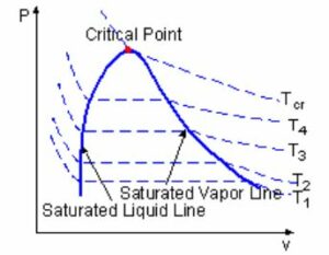
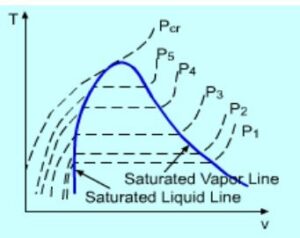
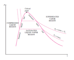
These boiling or condensing points vary with pressure for a particular component and can be denoted by what is called a saturated line in a PV or TV diagram, as shown below.

pic 2

Image Credit: PV diagram for a saturated line https://ecourses.ou.edu/cgi-bin/ebook.cgi?topic=th&chap_sec=02.2&page=theory

pic 3

Image source: TV diagram for a saturated line https://ecourses.ou.edu/cgi-bin/ebook.cgi?topic=th&chap_sec=02.2&page=theory

Definition of Saturated Liquid Line

A substance would exist in liquid form below its saturation line and as a mixture of vapor-liquid above it.

A saturated liquid line identifies the different temperature points in a PV diagram and different pressure points in a TV diagram of any substance beyond which it will cease to exist in pure liquid form.

At any point denoted by the saturated liquid line in the TV and or diagram above, if delta heat is added to the liquid at constant pressure, there will be no change in temperature but its gradual expansion and formation of vapor.

Saturated Liquid Line Temperature

Saturated liquid line temperature varies with system Pressure.

The saturation temperature of a substance shall increase with the increase in pressure, and hence the same is shown by a point higher up in the saturated liquid line of the PV/TV phase diagram.

Saturation liquid line temperature is the point where boiling starts when external heat is added, and the temperature remains the same until all the liquid has vaporized to vapor. This is also the temperature where condensation starts and continues till all the vapors are transformed into liquid. If heat is further removed from the system beyond the point of total vapor condensation, the liquid becomes sub-cooled. Thus the temperature of a sub-cooled liquid lies below the saturated liquid line temperature.

Frequently Asked Questions

Q. What is the definition of a Critical point?

Ans: Critical point signifies the point of a pressure-temperature curve at which liquid and its vapor can coexist.

The top limit of the liquid-vapor equilibrium curve is known as a critical point beyond this point liquid and gas are indistinguishable and form a super critical fluid. The pressure and temperature at this point are known as critical pressure and critical temperature, respectively.

If we consider the PV diagram of water, the point where saturated liquid line and saturated vapor line intersect each other is known as Critical point.

download

Image credit: Liquid vapor Critical point in a pressure temperature phase diagram https://en.wikipedia.org/wiki/Critical_point_(thermodynamics)

Q. What is a Triple point?

Ans: A point where a small change in pressure and temperature may lead to phase change of a substance.

The point in the pressure-temperature phase diagram, where solid, liquid and vapor phases of a pure substance co exist in equilibrium is known as Triple point.

Is Voltage Constant In Series: 3 Important Explanations

The voltage across each resistor in a series circuit is different depending on the resistance value. So, voltage is not constant in series. Only equal-valued resistors can yield the same voltage drop.

We use the word ‘constant’ to specify a fixed value of a quantity that remains unchanged. The voltage can never be a constant parameter in any electrical circuit. Each resistor has a different voltage drop through them in a series combination. Hence, voltage in series circuits is neither same nor constant. 

What is a series circuit? Explain the current and equivalent resistance in series circuits.

When we connect some resistors or impedance parameters in line one after another, it is called a series circuit. A series combination has the equal current everywhere in the circuit.

Equivalent resistance in a series pattern is the sum of all individual impedance. The voltage drops through all the resistors sum up to the total voltage. The voltage drop through each component in the circuit is different. These voltage drops are calculated by multiplying the total current with the resistor value.

Read more about….series circuit function

How to calculate voltage in a series circuit? Explain with a numerical example.

Is Voltage Constant In Series - circuit

The above network depicts a simple series circuit with three resistors of 5 ohm, 10 ohm and 20 ohm. Our goal is to find the voltage drops through them. We’ll first find out the equivalent resistance.

The equivalent resistance R= R1+R2+R3= 5+20+10= 35 ohm

So, the total current= the total voltage / the equivalent resistance = 10/35= 0.29 amp

The voltage through 5 ohm resistor= 5*0.29= 1.45 Volt

The voltage through 10 ohm resistor= 10*0.29= 2.9 Volt

The voltage through 20 ohm resistor= 20*0.29= 5.8 Volt

Is Voltage Constant In Series-FAQs

How does the voltage affect current in series circuits?

Each resistor in the series circuit receives the same current in series connection. We calculate the voltage drop across them using the known resistor values. 

A series circuit is the joint of multiple impedance elements. So, if the circuit breaks at any time, the entire circuit faults and no current flows. A very common example of this is series connection of bulbs with different luminosity. If we keep on adding more bulbs, the brightness eventually goes down.

Calculate the total voltage V in the series circuit shown below.

rD66u6VwnAMP waXSiVL91e5cge4mWRdV4pLc2vlH2XBaOwtI3NEHKRUw7WYJk e2 b3A1h4jJcuElcSM9LQdschRE6f74TNVQmovNC2V82 n7be

The network depicted above shows four resistors joined in series. A battery is present in the circuit with an unknown voltage V. The current flow is 0.25 amp. We have to find out the value of V.

The voltage drop through 6 ohm resistor= 6*0.25= 1.5 Volt

The voltage drop through 8 ohm resistor= 8*0.25= 2 Volt

The voltage drop through 10 ohm resistor= 10*0.25= 2.5 Volt

The voltage drop through 12 ohm resistor= 12*0.25= 3 Volt

Therefore, total voltage of the battery = V=1.5+2+2.5+3 = 9 Volt

What are the applications of voltage in series?

Series and parallel circuits are considered as the building blocks of circuit design. They are commonly used for many current limiting applications such as voltage dividing , transistor biasing, etc.

The voltage in series circuit has varied applications. Some common applications of the voltage in series are-

  1. Voltage divider circuits
  2. TV remote batteries
  3. Fire alarm
  4. Analog filters
  5. Resonant circuits
  6. Power-line filters
  7. LED light bulb strings
  8. Internal components of automotive vehicles

How can we find individual voltages in a series circuit?

Individual voltages of the resistors in a series circuit is obtained from the total current multiplied with the resistor value. 

Suppose, there are two resistors R1 and R2 connected in series with the battery V. Therefore, the equivalent resistance Req is R1+R2. So, the voltage across any resistor = value of the resistor x total current

The voltage across R1 = V1 = V.R1 / R1+R2 Volt

The voltage across R2 = V2 = V.R2 / R1+R2 Volt

Is voltage the same in series?

The voltage is neither the same nor constant in the series circuit. Voltage drop through each resistor is different in all cases except one where all the resistors in a series network have the same value.

When the resistors in the circuit are of equal value, then only voltage drops will be the same for all the resistors. Suppose, in a three resistor containing circuit, all the resistors are of R ohm. The equivalent resistance value = R+R+R = 3R. The voltage across any resistor = V*R/3R= V/3 volt.

Explain the voltage in series with a practical example.

One very interesting example of a series circuit in practical life is the classic christmas tree lighting. In this lighting, many tiny bulbs are connected in series.

We use these bulbs over the years. We can see that a particular portion of the lights aren’t working. This is due to the series connection. The lights are the combination of many such series connected strings. So, even if one bulb in a network is damaged, the entire part stops working.

How To Reset Camshaft Position Sensor: 7 Important Facts

The camshaft position sensor can be reset with the precautions of other car equipment.

The performance of the inductive sensor can be checked with a voltmeter and ohmmeter. Induction phase detector resistance in between 200 to 900 Ω

The measured resistance will be verified by comparing it with standard car data.

Switch off the ignition switch before measurement.

Take out the induction phase sensor (camshaft position sensor)

Connect two terminals of the voltmeter with the sensor.

Start the engine and let it run on idle

Your RMS value should be more than 0.75 V

What is a camshaft position sensor?

The camshaft position sensor provides valuable data to the engine control system.

It sends positional data of camshaft and crankshaft to the ECU. This position data helps estimate ignition points and injection points.

camshaft position sensor
Crank shaft /Camshaft position sensor Credit Wikipedia

The camshaft position sensor data is used in the engine control system to carry out further steps of combustion. For any engine, the ignition point is essential for better performance. This data can be calculated by the positioning of the camshaft.

Camshaft sensor principle: Functional principle

There are two sensors used to define the position of the crankshaft drive in the engine.

This sensor works on the hall principle. The sensor records the ring gear and changes the voltage reading accordingly.

The change in voltage is recorded and sent to the transmitter device. The voltage signal is studied in a transmitter device, and the required data is produced from it. Combining the signal from the camshaft sensor and crankshaft signal is helpful to get to know the position of the first cylinder in the top dead center.

Where is the location of the Camshaft Position Sensor?

This sensor is helpful for an engine control system to generate required data.

It is utilized to get position and monitor the rotation of the camshaft. The location of the sensor is nearby the cylinder head. This location is convenient to read timing rotor coupled with camshaft.

The electronic control unit (ECU) decodes the signal as the angle of the camshaft. It will calculate the recognition of the cylinder based on the signal given by this sensor.

In modern engine technology of auto start and stop, This sensor scans the cylinder on expansion stroke. It is helpful to supply fuel and advance spark with your acceleration act. A faulty camshaft sensor warns you about its condition before it is useless.

Is it safe to drive with a bad camshaft sensor?

This sensor is helpful to improve the engine performance with signals.

You will not face any driving problems. The engine performance and fuel economy can be affected by lousy camshaft sensors.

This sensor is necessary to improve the performance and fuel economy of any engine. An engine electronic control unit controls the fuel supply and other systems. This ECU collects signals from various sensors, which is ultimately used for further calculation of another system.

The lousy camshaft sensor affects the engine ignition system. It will not be helpful to calculate information for spark advance and fuel supply at the right time. It will always be recommended that you keep your camshaft sensor up to date for the proper functioning of your vehicle.

Can I replace my own camshaft position sensor?

The camshaft position sensor is rarely found at fault except for some physical damages.

Yes, You can replace the camshaft positioning sensor with a basic repair manual (DIY) for your vehicle. You should know its look and location in the car.

The camshaft sensor is working more for an extended period without losing its performance. If you want to replace it, you should know how it looks like and where its location is. Though the faulty replacement of the camshaft position sensor is not lead to stopping your vehicle from working. If you have made any mistake in replacement, you have to visit a mechanic for further guidance.

What causes a camshaft sensor to go bad?

Several aspects can affect the performance of camshaft position sensor

  • Damage due to water
  • Wear or tear
  • Damage due to corrosion of metallic parts
  • Damage due to engine oil leakage
  • Overheating or melting
  • Damage due to short circuit
  • Damage due to fire or spark
  • Other physical damages

There are many different possible reasons to affect the performance of the camshaft positioning sensor. The camshaft positioning sensor can work properly if you maintain your car regularly.

Which is a common problem for camshaft position sensor circuits?

The camshaft position sensor delivers a positional signal to the Electronic control unit circuit.

The sensor circuits can fail mostly with accidents or oil leakage from the engine. It will stop or reduce the signal sending capacity of the sensor.

The engine oil can cause leakage and affect the sensor if improper tightening or loss of engine components. The leakage oil stops the signal carrying capacity of wiring and circuits.

Can you clean a camshaft position sensor?

Periodic maintenance is required for any equipment associated with the car.

It is easily clean camshaft position sensor  with some care. Read more information below for proper steps for cleaning.

The first step is disconnecting the battery with an engine so that all electrical and electronics circuits remain off. Find the place of the camshaft position sensor in your vehicle.  

Disconnect the sensor’s three cables and remember it at the time of connection. Now clean the sensor with a cleaning solution and dry it before connecting.

Connect the sensor with its original three wire location. Connect the battery again and let the system run. You have cleaned the camshaft position sensor. Repeat this procedure after some period of time.

Firing Order And Firing Interval: 7 Facts You Should Know

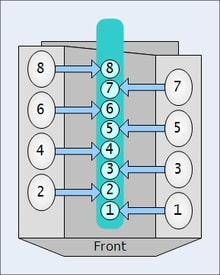
Vengine numbering 1

Firing order and firing interval have different meanings.

Firing order is the sequence in which the cylinders inside a multi cylinder engine are fired whereas firing interval is the time duration after which the same spark plug (cylinder) gets fired. Firing interval can be used in a single cylinder engine as well whereas firing order exists only when there are multiple cylinders used.

What is firing order?

Firing order helps reducing the chances of vibrations and regulates proper heat transfer.

As discussed in above section, firing order is the sequence with which cylinders inside the engine are fired. This term comes into play when there are multiple cylinders inside an engine.

Firing order of multi cylinder engines

Firing order means the chronology with which the cylinders are fired.

Below are some of the common firing orders used for different types of multi cylinder engine-

Number of cylindersFiring orderEngines using respective firing order
21-2Buick Model B
31-3-2Perodua Kancil engine
41-3-4-2,1-2-4-3Ford Taunus, Ford Kent
51-2-4-5-3,
1-3-5-4-2
Volvo 850, GM Atlas Engine
61-5-3-6-2-4,
1-4-3-6-2-5
Nissan L engine, Volkswagen V6s
71-3-5-7-2-4-6Radial engine
81-8-7-3-6-5-4-2,
1-8-7-2-6-5-4-3
Nissan VK engine, GM LS engine
91-10-9-4-3-6-5-8-7,
1-6-5-10-2-7-3-8-4-9
Dodge Viper V10, BMW S85, Ford V10
Table: Firing orders of multi cylinder engines with examples
Firing order and firing interval
Image: Numbering of cylinders in multi cylinder engine

Image credits: Wikipedia

What is firing interval?

Firing interval is the time between two successive firings of same cylinder/spark plug.

The spark plug has to fire during the ignition stroke. Firing of the spark plug is so precisely timed that it automatically fires when its the time for ignition stroke. If it takes x milliseconds to complete one full cycle then after every x milliseconds, firing takes place.

What is the significance of firing interval?

Anything which is more systematic and more even works more efficiently.

The significance of firing interval is as follows-

  • Minimizes vibrations.
  • Provides increased number of even pressure pulses.
  • Uneven firing interval causes throaty and growly sound in engines

What happens if firing order is not maintained?

The cylinders are fired in a particular sequence because of vibrations and heat transfer issues.

If the firing order is not maintained, lets say, if adjacent cylinders keep firing for a long time. Then the heat generated inside the engine will be very high and high sink temperature is always less efficient. The vibrations from the adjacent cylinders will have serious impact on bearings supporting the crankshaft.

Hence, a proper firing order is desirable.

How is firing order controlled/set?

The firing order is controlled by the ignition system of the engine. It provides necessary current to specific cylinders at specific times when ignition is required.

The distributor controls the spark in each spark plug of a multi cylinder engine in correct order. Changing the distributor position will directly affect the firing order of the engine. But this work needs to be done by expert mechanic. Changing of firing order is not recommended.

How is firing interval controlled/set?

The ignition system of the engine also controls the firing interval. It gives the spark at exact moment when required.

Firing interval is controlled by the action of cam which acts as circuit breaker. When the circuit breaker is open, capacitor starts charging creating a high voltage surge in the circuit. This high voltage surge creates the spark. The cam rotation is perfectly timed in a manner such that it breaks the circuit at the precise moment.  

Different parts used in controlling firing order and firing interval

The ignition system of the vehicle controls the firing order and firing interval of the engine. Most commonly used ignition system is magneto and battery ignition system.

In a magneto ignition system, following parts are used-

  • Magneto– A rotating magnet that controls the voltage.
  • Distributor– It distributes the current to the spark plugs in a correct sequence.
  • Capacitor– Capacitor are nothing two parallel metal plates whose each end is connected to circuit. It is used for storing charge
  • Spark plugs– Spark plugs are responsible for igniting the air fuel mixture.

Magneto itself generates power for the ignition system. Hence, it does not need any external source of power. In battery ignition system, batteries are used as external power source.

Two Surge Protectors In One Outlet: Essential Guidelines

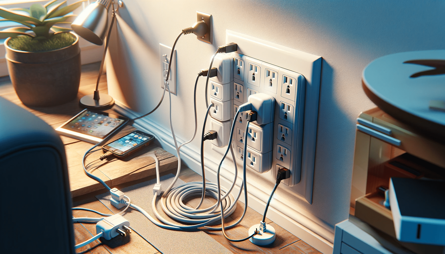
two surge protectors plugged into one outlet

This article elucidates what happens if we keep Two Surge Protectors In One Outlet. The power devices are susceptible to voltage surges. So we utilize surge protectors to avoid any unwanted electrical mishap.

Is it safe to install Two Surge Protectors In One Outlet? If we maintain the current limit of the socket, it is totally fine. Even Two Surge Protectors In One Outlet can serve as extra protection over a single one if connected in parallel. Both the surge protectors will work as backup for each other.

What are the surge protectors? 

A surge protector or a surge suppressor is an electrical device that provides protection to electrical appliances from voltage surges.

Fluctuations in electricity supply can cause sudden changes in voltage in home distribution. They are called spikes. If a spike lasts for a long time, we call it a surge. A surge can be harmful to delicate electronic devices. A surge protector is beneficial in protecting the appliances against voltage surges.

Read more about voltage…..Can voltage be negative: When, How, Exhaustive FAQs, insights

Why do we use surge protectors?

A voltage surge can cause permanent damage to electrical circuits. A surge protector is efficient in preventing voltage or power surges. It has more functions also.

There are two primary reasons behind using a surge protector. Firstly, a surge protector can accommodate multiple components in one single power socket. Secondly, a surge protector shunts the extra electricity through a semiconductor material to a grounding wire whenever it senses any surge.

How does a surge protector work?

Power surges damage electronic components or even lead to their untimely failure. A surge protector guards by passing current to the equipment plugged into it. The central part of a surge protector is a MOV.

The MOV acts as a pressure sensing valve. Whenever there is a sudden surge or spoke in the current, the MOV senses it. It brings down the resistance when there’s high voltage. Similarly, in low voltage, it increases resistance. The surge protector diverts extra current through the grounding wires of the outlets.

Two Surge Protectors In One Outlet- FAQs

Is it safe to overload surge protectors?

We should perform overloading of surge protectors carefully. We should keep in mind the rating given on the surge protector. 

Surge protectors are designed to incorporate devices that draw little current. It is not recommended that we use surge protectors for high amperage appliances like fridges, heaters, microwaves, etc., as they are heavy power users. However, we must not exceed the capacity of the power strip.

What are the necessary conditions to plug in Two Surge Protectors In One Outlet?

Plugging two surge protectors in one outlet is a pretty safe approach. To ensure better safety, one can use outlets that support a multi-device set-up (e.g., duplex socket).

However, some safety measures need to be followed-

1. We should never connect a lot of devices with both the surge protectors. The combined load of them may overload and burn them.

2. We should put the surge protectors in series so that if somehow one fails, the other one compensates for the entire load.

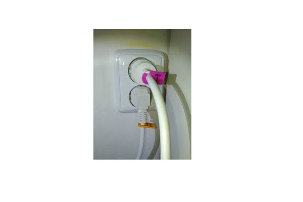
Two Surge Protectors In One Outlet
Credits: Quora

Can we plug an extension cord into a surge protector?

Although we run a risk of catching fire if we plug an extension cord into a surge protector or reverse, the phenomenon isn’t impossible. We can push the extension cord plug to the outlet of the surge protector.

With correct gauge and ampacity, daisy-chaining extension cords and surge protectors can be performed with overloading and fear of electrical hazards. But if any of the devices are improper or weak, the process can really turn into danger. Ratings of both of them must be equal.

Is it possible to plug two surge protectors?

It is not at all an illegal method to plug one surge protector into another. Though, this is often regarded as a hazardous task due to the fear of overload.

Surge protectors contain a Metal Oxide Varistor (MOV). When it fails during any surge, the protector loses its capability. So, if we plug in another surge protector, then that acts as protection and prevents any mishap. Surge protectors with failure indicators are even better. They don’t get destroyed.

How to daisy chain surge protectors? 

Daisy-chaining surge protectors are often believed to be malpractice. Daisy chain means the connection of equipment in series. Daisy chains can lead to power overload and fire.

Along with the warnings, it is also a bad idea to daisy chain surge protectors. There are some expensive surge protectors that come with a sensing circuit. It monitors the entire circuitry and indicates surges through the LED. The use of these types of surge protectors can be useful if we want to daisy chain them.

Is a surge protector the same as a fuse?

It is a very common misconception that a fuse or a circuit breaker is the same as a surge protector. But a surge protector is a completely different product.

The main difference between a fuse and a surge protector is, the former protects a circuit from excess current while the latter protects from excess voltage. A fuse blows away in a very high current. The surge protector bypasses any voltage surge through low resistance, and it doesn’t get burnt as well.

Coolant vs Refrigerant: 7 Important Factors Related To It

Refrigerant 199x300 1

Coolant and refrigerant are not entirely different. This article discusses about the topic Coolant vs Refrigerant in detail.

Coolant is a broad term and refers to a fluid that absorbs heat from the system. This way the temperature of the system can be regulated. When the temperature needs to be reduced below ambient temperature, then the coolant is referred as a refrigerant. Hence, all refrigerants are coolants in broader sense.

Definition of coolant

As discussed above, coolant can be any fluid that is used to remove heat from the system and reduce the temperature of the system.

The coolant can work without changing its phase (whether liquid or gas) or by changing its phase (liquid to gas and gas to liquid).

Uses of Coolant

A coolant is used in places where the temperature needs to be regulated. Excess heat can create a lot of problems in engines, machine components etc.

Different places where coolant is used are-

  • Inert gases are used as coolants in nuclear reactors.
  • Vehicle engines use cooling fluid/ water jackets around engine to absorb the excess heat generated in the cylinder.
  • Rocket engine nozzles have small tubes through which liquid oxygen is passed that cools the nozzle to a desired temperature, without which the metals used in nozzle wouldn’t have survived the high temperature generated because of exhaust gases.

Types of coolant

Coolant comes in various forms and phases. It is important to know the nature of coolant because an improper coolant will not be able to regulate the temperature of the system to required value.

The different types of coolants used in industry are-

  • Gaseous- Hydrogen, Boron, Sulfur Hexafluoride are commonly used gas coolants. Hydrogen is used in turbogenerators, Boron in nuclear reactors and Sulfur Hexafluoride in switches, transformers or other kind of circuit breakers etc.
  • Two phase- These types of coolants uses both the phases of coolant that is liquid and gas. These coolants are usually used in applications where desired temperature is below ambient temperature. These coolants are called as refrigerants.
  • Liquids- Water is the most common liquid coolant. But it cannot be used while dealing with metals due to corrosive nature of metals. Various mineral oils are used as coolant in place of water to cool machine components. For example, special oil is used to cool the job while machining on lathe.

Definition of refrigerant

Refrigerants are the coolants that are used in low temperature applications. Refrigerants use their latent heat of vaporization to reduce the temperature to significantly low value.

Refrigerants bring with them a lot of environmental concerns which is why there are many rules and regulations of refrigerants.

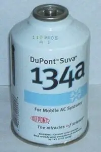
Refrigerant
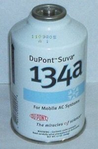
Image: Refrigerant

Image credit: Stephanie~commonswiki, Can of DuPont R-134a refrigerantCC BY-SA 3.0

How do refrigerants cool the system?

Refrigerants absorb heat and change their phase to achieve the desirable temperature. Some gas cycles may use only one phase of the refrigerant for example Bell Coleman cycle or Reverse Brayton cycle.

In a typical refrigeration cycle, the refrigerant enters the system in liquid form. It absorbs the heat from the system and gets converted into gaseous form. Later on, the gaseous refrigerant is converted back to liquid state so that it can be used again.

Coolant Vs Refrigerant
Image: The observed stabilization of HCFC concentrations (left graphs) and the growth of HFCs (right graphs) in earth’s atmosphere.

Image credits: Wikipedia

What are desirable properties of refrigerants?

The use of refrigerants is regulated due to their toxic and inflammable nature. They also give out green house gases which are harmful for ozone layer.

Due to above reasons, some refrigerants are banned. An ideal refrigerant has following properties-

  • Non toxic
  • Non corrosive
  • Non flammable
  • No green house gas emission and ozone layer depletion potential.
  • Freezing point below the target temperature.

Is AC coolant and engine coolant same?

Both AC coolant and engine coolant are used for cooling. But their applications and mechanism differ from each other.

Water is typically used as engine coolant. It cools down the engine by absorbing heat and transferring it to the outside air and also transfers heat to the cabin of the vehicle when vehicle heating feature is turned ON. It is mixed with anti freeze substances so that the water does not get frozen. AC coolant is used for absorbing heat from the cabin and emitting out to the atmosphere. The AC coolant will change its phase from liquid to gas and back to liquid.

Hence, the major difference between the two is the application (one is used to cool engines and other is used to cool the cabin) and other difference is the mechanism of cooling (engine coolant does not change its phase whereas AC coolant switches its state from liquid to gas time to time).

Saturated Liquid vs Subcooled Liquid: 3 Critical Facts

Article 3 image 1

Saturated Liquid VS Subcooled Liquid: Need to know Critical Facts

Saturated liquid and subcooled liquid are the different stages during the phase change process of a pure liquid. The principal phases of a pure substance are Solid, Liquid, and Gas.

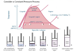
Subcooled liquid refers to that phase of a substance where it exists in liquid form at a temperature below its boiling point at the system pressure. The saturated liquid is a liquid that is about to vaporize, which means any decrease in pressure without changing its temperature causes it to boil.

Saturated Liquid Vs Subcooled Liquid

Image Credit: Saturated liquid Vs Subcooled liquid https://s3.studentvip.com.au/notes/11438-

Any liquid, whether in its pure form or in a mixture exerts a specific pressure over the surface of the liquid at a particular temperature, which is called the vapor pressure of the substance at that temperature. If the temperature of the liquid increases, its vapor pressure also increases. As this vapor pressure equals the pressure of the surrounding atmosphere, the liquid starts to boil. The liquid at its boiling point is called a saturated liquid.

For example, water is a saturated liquid at its boiling point of 100°C under the atmospheric condition at Sea level or 1-atmosphere pressure. As water is cooled below 100°C, it becomes sub-cooled. As the pressure is increased beyond 1 atmosphere, the boiling point of water increases, or it becomes a sub-cooled liquid at 100 °C.

Subcooled liquid example

Any liquid below its boiling temperature at a given pressure can be considered as a Subcooled liquid.

Water boils at 373 °K(100° C). Now water at room temperature293°K(25°C) andat normal atmospheric pressure is an example of a Subcooled liquid.

Certain conditions that cause a liquid to be Subcooled are:

At a given system pressure when the liquid attains a temperature lower than its saturation temperature. When the liquid is at a pressure higher than its saturation pressure at the given temperature. Thermodynamically the liquid has lower enthalpy and Specific volume than that of a saturated liquid.

Article 3 image 1

Image credit: T-v diagram representing phase change for water at constant pressure https://engineering.purdue.edu/CFDLAB/class/me200/filesFall2010/me200_notes_f10_week3.pdf

Some other examples of sub cooled liquid are:

  • Liquid ammonia at a temperature below -33.3°C and pressure 1 bar or higher.
  • Liquid ammonia at a temperature below -50°C and pressure 0.41 bar or higher.
  • Ethylene glycol at a temperature  below 197 C and pressure 1 bar or higher
  • Ethyl alcohol at a temperature below 77.8 C and pressure 1 bar or higher.

As can be seen above, in the example of liquid ammonia, it can exit in sub-cooled conditions at different conditions of pressure and temperature. -33.3°C is the saturation temperature of ammonia at 1 bar pressure. Similarly, for a temperature of -50°C, the corresponding saturation pressure for ammonia is 0.41 bar (approx).

Subcooled liquid pressure

A liquid with a pressure higher than its saturation pressure at the given temperature is said to be a Sub-cooled or Compressed liquid.

Sub-cooled liquid means that the temperature of the liquid is lower than the saturation temperature for that particular pressure and a compressed liquid means that the pressure of the liquid is superior than the saturation pressure for the given temperature. Both the terms can be used alternatively.

Since liquids are incompressible in nature, their properties are relatively independent of pressure. Subcooled liquids are defined by:

  • Higher pressure than a saturated liquid(P>Psatat a given T)
  • Lower temperature than a saturated liquid(T<Tsat at a given P)
  • Lower enthalpy than a saturated liquid(h<hfat a given T or P)
  • Lower internal energy than a saturated liquid(u<ufat a given T or P)
  • Lower specific volume than a saturated liquid (v<vf at a given T or P)

Enthalpy is mostly affected by pressure, a more accurate relationship for h

hf~hf@T+vf(P-Psat)

pv

Image Credit:P-V Diagram of a pure substance http://processandinstrumentation.blogspot.com/

Frequently Asked Questions

Q. What is the difference between Saturated and Subcooled liquid?

Ans:Thoughboth Saturated liquid and Subcooled liquid are the two phases of the same liquid, they are quite different from each other.

Subcooled is the condition where the liquid is colder than the minimum temperature (saturation temperature), which is required to keep it away fromboiling. On the contrary saturated liquid is the condition when the liquid is almost at its boiling point.

In the case of saturated liquid, if the pressure is further lowered andkeeping the temperature constant, the saturatedliquid will start to boil. On the other hand, the liquid will besub-cooled if pressure is increased beyond its saturated pressure at its boiling point.

Q. Why is sub-cooling desirable in a refrigeration system?

Ans:A sub-cooled liquid increases the energy efficiency of a refrigeration system as it has lower specific volume

The refrigerant is sub cooled in the condenser to avoid the early vaporization of the refrigerant before heading towards the expansion device.

If proper condenser surface area is not provided to ensure proper subcooling, the refrigerant may partially evaporate in the piping as it moves to the expansion device. If the refrigerant partially evaporates before entering the expansion device, it will require higher refrigerant volume to be pumped to achieve the same cooling. This increases the pumping cost and hence the energy consumption.