9 Real World Magnetic Flux Examples That You Should Know

magnetic flux

Every magnetic regardless of shape and size, has two poles from which imaginary lines pass between the two poles, called magnetic flux. Here facts on magnetic flux example are given.

  • Earth’s magnetic field
  • The magnetic field of celestial stars
  • Mariner’s compass
  • Bar magnets
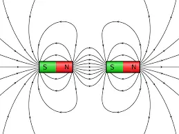
  • The magnetic field between two magnets
  • MRI scanners
  • Microwave oven
  • The magnetic field of planets
  • The magnetic field in motors
  • Magnetic filed in an electronic device

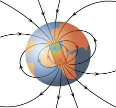
Earth’s magnetic field

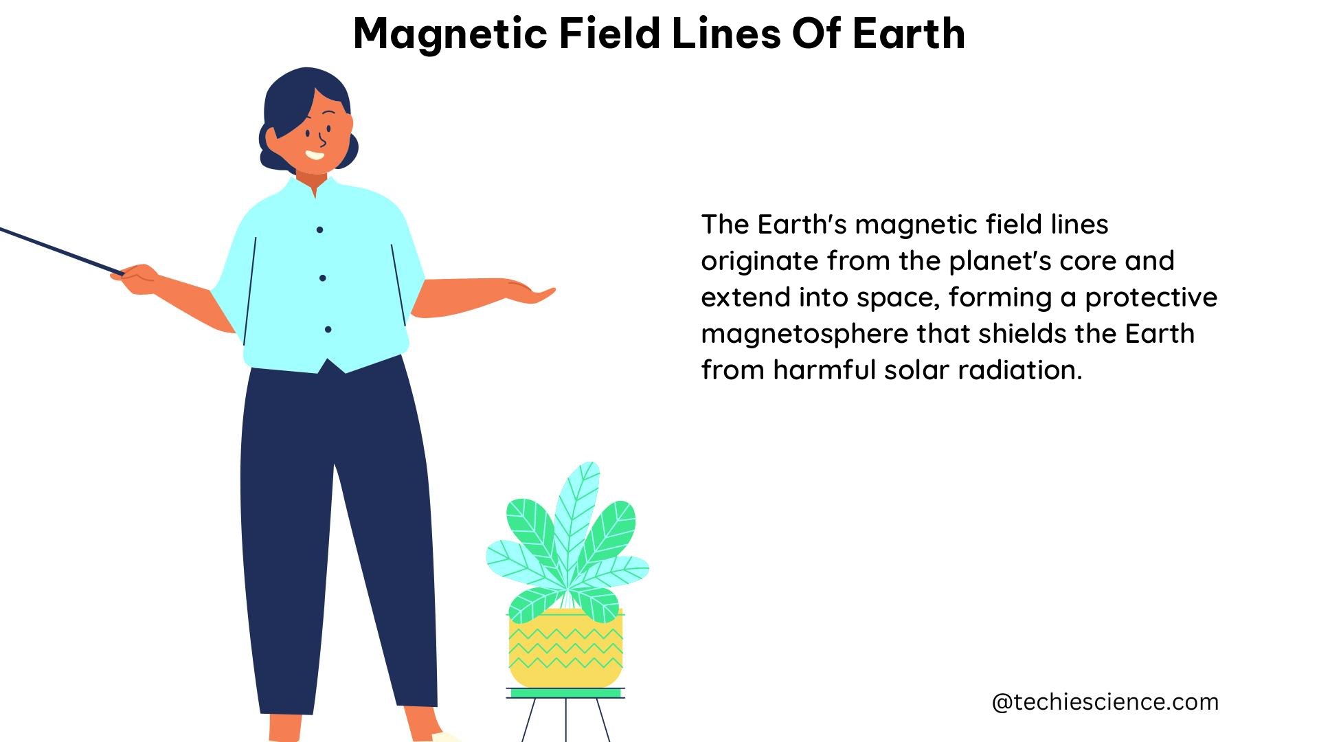
Our earth is a giant magnet whose field lines are outrageous from the core to space. The earth’s magnetic flux lines shield the earth by avoiding space dust and harmful solar radiation.

The magnetic field of celestial stars

The celestial stars, like the sun consist of a magnetic field due to the motion of conductive plasma inside them. A neutron star consists large magnetic field.

Mariner’s compass

The navigation can possibly use a compass only due to the magnetic field. It consists of a set of magnetic needles that generate flux lines and help determine direction. The needle points in the direction of the opposite polarity to determine the direction.

Bar magnets

We know that every magnet are of bi-poles, a south pole, and a north pole. The magnetic fields are generated around the bar magnet in such a way that the flux lines flow from the north to the south pole.

File:VFPt magnet B.svg - Wikimedia Commons
Direction of magnetic flux lines in bar magnet
Image credits: Wikimedia commons

The magnetic field between two magnets

When two magnets are placed nearer to each other, the magnetic field is generated between them. These magnetic fields are responsible for the attraction and repelling ability of the magnet. If opposite poles are facing each other, both magnets are attracted. If like poles are facing each other, they repel.

MRI scanners

The working principle of MRI scanners depends on the magnetic field. The scanner consists of a large magnet that generates a magnetic field. These magnetic fields are used to imagine the human body and detect a fault.

Microwave oven

The microwave oven generates a magnetic field that can oscillate back and forth 4.9 billion times every second. This oscillation causes the molecules to flip and produces friction, generating heat utilized for cooking the food item.

The magnetic field of planets

Most of the planet has a magnetic field that may be strong or weak. These fields help the planet for stable rotation around the sun and protect the planet from radiation.

The magnetic field in motors

All the motors are provided with rotating magnets which helps the machine to be in sync with the speed of air. The magnetic field enables the motor to run efficiently.

Magnetic filed in an electronic device.

Every electronic device produces a magnetic field by electric field. The motion of the charges generates the magnetic field in the machine. The magnetic field in an electronic device is temporary and disappears as soon as the current is turned off.

How to use magnetic flux?

Magnetic flux is determined by considering the area occupied by field lines that pass through a closed surface and the direction of orientation of the lines.

Since magnetic flux generally represents the lines that pass between the two poles in a closed-loop, the area of the loop must be known to use the magnetic flux. The magnetic flux is a tool to describe the effect of the magnetic force on anything under the influence of a magnetic field; thus particular area must be chosen for the magnetic flux.

The formula gives the magnetic flux

φB=B.A=B.A cos θ

Where B is the magnetic field, A is an area of the region, and θ is the angle made by the magnetic field on the region.

The bare eyes cannot see the magnetic flux, but it can be visualized using the iron filings sprinkled on paper.

When to use magnetic flux?

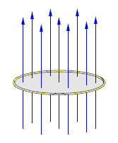
T0 illustrate the effect of a magnetic field passing through a region or closed space, the magnetic flux is used. Since the area of the region where the magnetic field lines are passing contributes to the magnetic flux, the angle at which the line intersects the area is also important.

When we calculate the magnetic flux, the glancing angle contributes to the magnetic flux.

  • When the angle between the magnetic field and area vectors are normal to each other, i.e., 90°, the flux passing through the region is low.
  • If the angle is 0°, the probability of flux passing between the pole pieces is more.

This illustrates the effect of magnetic field force exerted on that region of space.
File:Magnetic flux.png - Wikimedia Commons, Magnetic Flux Example
Magnetic flux
Image credits: Wikimedia commons

9 Magnetic Flux Examples

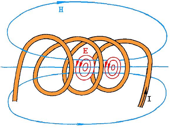
Magnetic flux in a solenoid

Since we know that magnetic flux is the number of magnetic field lines on a closed surface, solenoid consists of the uniform magnetic field, which produces maximum flux directed along the length of the coil.

Magnetic flux in the transformer

The transformer’s primary coil induces the current in the core to oppose the charges, creating a magnetic flux. This magnetic flux acts as a linkage that binds both the winding together when there is an increase or decrease in the AC power supply in the opposite direction.

Magnetic flux lines around the earth

The earth’s magnetic flux is invisible lines always directed south to the north pole. These flux lines trap the unwanted radiation and create a magnetosphere around the earth as a shield.

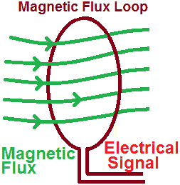
Magnetic flux in the wire loop

Magnetic flux is created if a magnet moves towards the wire loop. These fluxes are in a downward direction and increase with the current. The magnetic fields are always in the opposite direction and oppose the flux. If the loop is closed, the total magnetic flux in the loop is zero because the number of field lines entering and leaving the loop is the same.

File:The Mechanics of a Magnetic flux loop.png - Wikimedia Commons
Wire loop as Magnetic flux example
Image credits: Wikimedia Commons

The magnetic flux of the coil

A moving coil generates the magnetic field and magnetic flux in the opposite direction. The change in magnetic environment causes emf in the coil. The change in magnetic flux in the coil is associated with the voltage to be induced. The induced voltage is always negative of the change in magnetic flux.

The magnetic flux of toroid

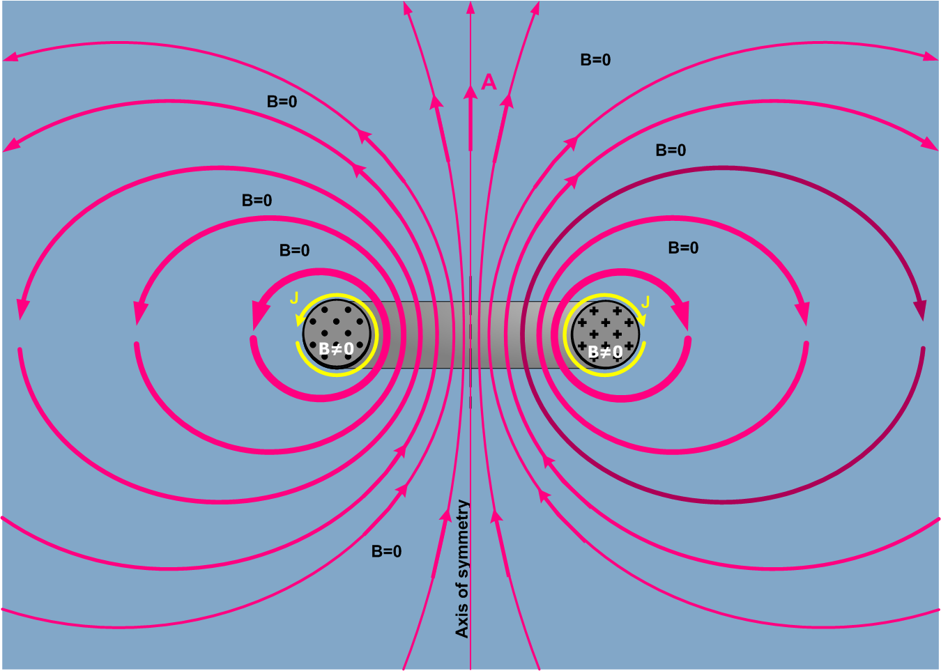
Toroids are donut-shaped coils made of powdered iron. These are used as an inductor to operate at low frequency in circuits. When the current is passed, magnetic fields are generated inside the coil, and the magnetic field outside the coil is zero.
File:Magnetic Vector Potential Circular Toroid.png - Wikimedia Commons
Toroid As magnetic flux example
Image credits: Wikimedia commons

The magnetic flux of a bar magnet

In a bar magnet, the magnetic flux is always directed north to the south pole. The flux creates a closed-loop structure around the magnet. The magnetic flux around the bar magnet will be zero if the magnetic field is parallel to the area.

Magnetic flux in electric motors

The permanent magnets fitted inside the electric motor generate the magnetic flux. The flux can boost or oppose the action of the motor. The boosting flux helps the motor to increase the torque, and the opposing flux makes the motor run with an existing magnetic field.

The magnetic flux generated in the DC motor is due to the magnetic field’s rotating loop through the electromagnetic induction process.

Magnetic flux in magnetic circuits

A magnetic circuit is made up of more than one closed-loop magnetic component consisting of magnetic flux. The ferromagnetic materials such as iron and nickel confine the path of the magnetic field, and thus, magnetic flux is generated.

This flux efficiently channels the magnetic field in other devices. These flux flow through the area perpendicular to the magnetic field. The magnetic flux through the magnetic circuits drives the magneto-motive force through the circuit.

Conclusion

Let us wrap up this post by stating magnetic flux is vector quantity which associated with the direction of the magnetic field. These are invisible imaginary lines which describes the intensity and direction of the magnetic field. The real world magnetic flux example give an account on behavior of these imaginary lines.

Also Read:
Is Static Electricity Magnetic?

is static electricity magnetic

Static electricity and magnetic fields are both related to the behavior of electric charges, but they have some key differences. While they can interact with each other in certain situations, they are distinct phenomena with their own unique properties and characteristics.

Understanding Static Electricity

Static electricity is the buildup of electric charge on the surface of a material, which can occur when there is friction, separation, or contact between two different materials. This charge can remain on the surface of the material until it is neutralized by an oppositely charged object or it dissipates over time.

The key characteristics of static electricity are:

  1. Charge Separation: When two different materials are brought into contact and then separated, electrons can be transferred from one material to the other, creating a charge imbalance. This charge separation is the basis of static electricity.

  2. Electrostatic Force: The accumulated charge on the surface of a material creates an electrostatic force, which can attract or repel other charged objects. This force is described by Coulomb’s law, which states that the force between two point charges is proportional to the product of their charges and inversely proportional to the square of the distance between them.

  3. Electrostatic Potential: The amount of work required to move a unit positive charge from infinity to a specific point in an electrostatic field is known as the electrostatic potential. This potential can be measured in volts (V) and is often used to describe the strength of a static electric field.

  4. Electrostatic Discharge: When the accumulated charge on a material is suddenly released, it can result in an electrostatic discharge, commonly known as a “static shock.” This discharge can be a nuisance and, in some cases, can even be damaging to electronic devices.

Understanding Magnetic Fields

is static electricity magnetic

Magnetic fields, on the other hand, are created by moving electric charges, such as the flow of electricity in a wire or the motion of electrons around an atom’s nucleus. Magnetic fields can also be created by permanent magnets, which have a north and south pole that attract or repel other magnetic materials.

The key characteristics of magnetic fields are:

  1. Magnetic Flux: Magnetic flux is a measure of the number of magnetic field lines passing through a given area. It is typically measured in webers (Wb) or teslas (T), where 1 T = 1 Wb/m².

  2. Magnetic Field Strength: The strength of a magnetic field is measured in units of tesla (T) or gauss (G), where 1 T = 10,000 G. The strength of a magnetic field can vary depending on the source and the distance from the source.

  3. Magnetic Poles: Magnetic fields have two poles, a north pole and a south pole. These poles are the source of the magnetic field and can attract or repel other magnetic materials.

  4. Electromagnetic Induction: When a changing magnetic field is present, it can induce an electromotive force (EMF) in a nearby conductor, which is the principle behind electric generators and transformers.

Interaction between Static Electricity and Magnetic Fields

While static electricity and magnetic fields are distinct phenomena, they can interact with each other in certain situations. For example:

  1. Electromagnetic Induction: A moving magnetic field can induce an electric current in a conductor, which is the principle behind electric generators and motors. This is known as electromagnetic induction.

  2. Magnetic Field of a Moving Charge: A moving electric charge can generate a magnetic field, which is the principle behind electromagnets and magnetic materials.

  3. Charged Particle Motion in Magnetic Fields: Charged particles, such as electrons or ions, can be deflected by a magnetic field, which is the basis for many particle accelerators and other applications.

  4. Magnetic Effects of Static Electricity: While static electricity itself is not magnetic, the motion of charged particles created by static electricity can generate a weak magnetic field.

Quantifying Static Electricity and Magnetic Fields

In terms of measurable and quantifiable data, static electric fields can be measured in units of volts per meter (V/m), while magnetic fields can be measured in units of teslas (T) or gauss (G).

The strength of static electric and magnetic fields can vary depending on the source and the distance from the source. For example:

  • A static electric field near a charged object can be several thousand volts per meter.
  • A magnetic field near a permanent magnet can be several hundred gauss.

It’s also worth noting that static electric fields can have potential health effects, such as causing shocks or interfering with electronic devices. However, the scientific evidence to date suggests that exposure to static electric and magnetic fields at typical levels found in the environment is not harmful to human health.

Practical Applications of Static Electricity and Magnetic Fields

Static electricity and magnetic fields have a wide range of practical applications in various fields, including:

  1. Electrostatic Printing: Static electricity is used in photocopiers and laser printers to transfer toner particles to the paper.
  2. Electrostatic Painting: Static electricity is used to spray paint onto surfaces, allowing for a more even and efficient coating.
  3. Magnetic Separation: Magnetic fields are used to separate magnetic materials from non-magnetic materials, such as in the recycling of metals.
  4. Magnetic Resonance Imaging (MRI): Powerful magnetic fields are used in MRI machines to generate detailed images of the human body.
  5. Electric Motors and Generators: The interaction between electric currents and magnetic fields is the basis for the operation of electric motors and generators.

Conclusion

In summary, while static electricity and magnetic fields are related to the behavior of electric charges, they are distinct phenomena with their own unique properties and characteristics. Understanding the differences and interactions between these two concepts is crucial for many applications in physics, engineering, and technology.

References:

Does the Magnitude of Magnetic Field Change?

does the magnitude of magnetic field change

The magnitude of a magnetic field can change based on various factors, including the distance from the source, the strength of the current or magnet generating the field, and the presence of other magnetic materials or fields. Understanding the factors that influence the magnitude of a magnetic field is crucial in various applications, from magnetic measurements to nuclear magnetic resonance (NMR) phenomena.

Factors Affecting the Magnitude of Magnetic Field

Distance from the Source

The magnitude of a magnetic field decreases with the square of the distance from the source, as described by the inverse-square law. This relationship is expressed mathematically as:

$B = \frac{\mu_0 I}{2\pi r}$

where:
– $B$ is the magnetic field strength
– $\mu_0$ is the permeability of free space (4$\pi$ × 10^-7 T⋅m/A)
– $I$ is the current in the source
– $r$ is the distance from the source

This means that as the distance from the source increases, the magnetic field strength decreases rapidly. For example, doubling the distance from the source will result in a four-fold decrease in the magnetic field strength.

Strength of the Current or Magnet

The magnitude of the magnetic field is directly proportional to the strength of the current or the strength of the permanent magnet generating the field. This relationship is expressed by the following equations:

For a current-carrying wire:
$B = \frac{\mu_0 I}{2\pi r}$

For a permanent magnet:
$B = \frac{\mu_0 M}{4\pi}$

where:
– $M$ is the magnetization of the permanent magnet

Increasing the current or the strength of the permanent magnet will result in a corresponding increase in the magnitude of the magnetic field.

Presence of Magnetic Materials

The presence of magnetic materials, such as ferromagnetic or paramagnetic materials, can significantly affect the magnitude of the magnetic field. These materials can either enhance or distort the magnetic field, depending on their magnetic properties.

Ferromagnetic materials, like iron, nickel, and cobalt, can concentrate the magnetic field lines, leading to an increase in the local magnetic field strength. This effect is known as magnetic flux concentration and is commonly used in the design of transformers, electromagnets, and other magnetic devices.

Paramagnetic materials, on the other hand, can slightly enhance the magnetic field, while diamagnetic materials, such as copper and water, can slightly reduce the magnetic field.

Magnetic Measurements and Non-Uniformity

does the magnitude of magnetic field change

In the context of magnetic measurements, the uniformity of the magnetic field is crucial. Non-uniformity in the magnetic field can produce significant effects when making magnetic measurements on superconducting materials. This non-uniformity can lead to errors in the measurement of the magnetic moment of the sample, especially in systems where the field is changed while holding the sample stationary.

When the sample is subjected to a time-varying magnetic field, it can affect the magnetic history of the sample, leading to the motion of vortices, eddy currents, and other dynamic effects. These effects can introduce errors in the measurement of the magnetic moment, as the sample’s response to the changing field may not be instantaneous.

To account for the non-uniformity of the magnetic field, researchers often divide the wire’s length into N equal segments and measure the magnetic field values at equal intervals along the current’s path. The net force on the wire is then calculated as the sum of the forces on all these short segments.

Magnetic Field in NMR Phenomena

In NMR (Nuclear Magnetic Resonance) phenomena, the magnetic field plays a significant role in the number of measurable spin states (eigenstates) of a system. The number of observable spin states can be 0, ½, 1, or 2, depending on the strength of the external magnetic field.

When an unmagnetized sample of tissue is placed in an external magnetic field, net magnetization (M) develops, initially growing in the longitudinal direction. This growth is a simple exponential with a time constant T1, as the individual spins seek to align with the magnetic field.

Magnetization transfer is a process in which energy is transferred between macromolecular and free-water pools by irradiating the tissue with an off-resonance RF-pulse. This process can affect image contrast in NMR imaging, as it alters the magnetic properties of the tissue.

Examples and Numerical Problems

  1. Example 1: Magnetic Field of a Current-Carrying Wire
  2. Consider a current-carrying wire with a current of 5 A.
  3. The magnetic field at a distance of 2 cm from the wire is given by:
    $B = \frac{\mu_0 I}{2\pi r} = \frac{4\pi \times 10^{-7} \text{ T⋅m/A} \times 5 \text{ A}}{2\pi \times 0.02 \text{ m}} = 1 \times 10^{-4} \text{ T}$

  4. Example 2: Magnetic Field of a Permanent Magnet

  5. Consider a permanent magnet with a magnetization of 1.2 T.
  6. The magnetic field at a distance of 5 cm from the magnet is given by:
    $B = \frac{\mu_0 M}{4\pi} = \frac{4\pi \times 10^{-7} \text{ T⋅m/A} \times 1.2 \text{ T}}{4\pi} = 1.2 \times 10^{-4} \text{ T}$

  7. Numerical Problem: Magnetic Force on a Current-Carrying Wire

  8. A current-carrying wire with a length of 10 cm is placed in a non-uniform magnetic field.
  9. The magnetic field values at different points along the wire are:
    • $B_1 = 0.5 \text{ T}$
    • $B_2 = 0.6 \text{ T}$
    • $B_3 = 0.7 \text{ T}$
  10. The current in the wire is 2 A, and the angle between the current and the magnetic field is 30°.
  11. Calculate the net force on the wire.

Solution:
– Divide the wire into 3 equal segments, each with a length of 3.33 cm.
– Calculate the force on each segment using the formula $F = ILBsin\theta$:
– Segment 1: $F_1 = 2 \text{ A} \times 0.0333 \text{ m} \times 0.5 \text{ T} \times sin(30°) = 0.0289 \text{ N}$
– Segment 2: $F_2 = 2 \text{ A} \times 0.0333 \text{ m} \times 0.6 \text{ T} \times sin(30°) = 0.0347 \text{ N}$
– Segment 3: $F_3 = 2 \text{ A} \times 0.0333 \text{ m} \times 0.7 \text{ T} \times sin(30°) = 0.0404 \text{ N}$
– The net force on the wire is the sum of the forces on the individual segments:
$F_\text{net} = F_1 + F_2 + F_3 = 0.0289 \text{ N} + 0.0347 \text{ N} + 0.0404 \text{ N} = 0.104 \text{ N}$

These examples and numerical problems demonstrate how the magnitude of the magnetic field can change based on various factors, such as distance, current/magnet strength, and the presence of magnetic materials. They also illustrate the importance of considering non-uniformity in the magnetic field when making accurate magnetic measurements.

References

  1. Effects of Non-Uniform Magnetic Fields on Magnetic Measurements
  2. Magnetic Force on a Current-Carrying Wire
  3. NMR Phenomenon Quiz

Is Gravity Electromagnetic?

is gravity electromagnetic

Gravity and electromagnetism are two fundamental forces in physics, and while they have not been definitively shown to be the same force, there are some intriguing connections between the two. This comprehensive guide delves into the technical details and advanced concepts surrounding the relationship between gravity and electromagnetism, providing a valuable resource for physics students and enthusiasts.

Gravitoelectromagnetism (GEM): The Gravitational Analogue of Electromagnetism

Gravitoelectromagnetism (GEM) is a theoretical framework that attempts to describe gravity in a manner analogous to electromagnetism. GEM is an approximate reformulation of gravitation as described by general relativity in the weak field limit. In this framework, the gravitational field is represented by two components: the gravitoelectric field and the gravitomagnetic field.

Gravitoelectric Field

The gravitoelectric field is the gravitational analogue of the electric field in electromagnetism. It arises due to the presence of mass, just as the electric field arises due to the presence of electric charge. The gravitoelectric field can be calculated using the following formula:

$\vec{g} = -\nabla \Phi$

Where:
– $\vec{g}$ is the gravitoelectric field
– $\Phi$ is the gravitational potential

Gravitomagnetic Field

The gravitomagnetic field is the gravitational analogue of the magnetic field in electromagnetism. It arises due to the motion of mass, just as the magnetic field arises due to the motion of electric charge. The gravitomagnetic field can be calculated using the following formula:

$\vec{B}_g = \frac{2G}{c^2}\vec{J}$

Where:
– $\vec{B}_g$ is the gravitomagnetic field
– $G$ is the gravitational constant
– $c$ is the speed of light
– $\vec{J}$ is the mass current density

The gravitomagnetic field can cause a moving object near a massive, non-axisymmetric, rotating object to experience acceleration not predicted by a purely Newtonian (gravitoelectric) gravity field. This effect, known as frame-dragging, has been experimentally verified and is one of the last basic predictions of general relativity to be directly tested.

Measuring the Strength of Gravity

is gravity electromagnetic

The strength of gravity can be measured using various techniques, each with its own advantages and limitations. Here are some of the most common methods:

Dropping Mass Experiment

In this experiment, a mass is dropped from a known height, and the time it takes to fall is measured. The acceleration due to gravity can then be calculated using the formula:

$g = \frac{2h}{t^2}$

Where:
– $g$ is the acceleration due to gravity
– $h$ is the height from which the mass is dropped
– $t$ is the time taken for the mass to fall

Torsion Balance

The torsion balance is one of the most precise ways to measure the strength of gravity. It consists of two small masses suspended by a thin wire or fiber, and the gravitational attraction between the masses is measured by the twisting of the wire or fiber. The gravitational constant $G$ can then be calculated using the formula:

$G = \frac{Fd^2}{m_1m_2}$

Where:
– $F$ is the force of gravitational attraction between the masses
– $d$ is the distance between the masses
– $m_1$ and $m_2$ are the masses

Researchers around the world are continuously developing more sophisticated versions of the torsion balance to improve the precision of gravity measurements.

NIST Gravity Measurement

At the National Institute of Standards and Technology (NIST), a team uses a set of eight masses to measure the gravitational constant $G$. The current best estimate for $G$ is $6.6743 \times 10^{-11} \, \mathrm{m^3 \, kg^{-1} \, s^{-2}}$. However, there is still some disagreement among the world’s best experimental results, which has become a source of consternation for scientists.

Measuring Gravity at Short Distance Scales

Researchers are using clouds of ultracold atoms to try to measure gravity at short distance scales, which may provide further insights into the connection between gravity and electromagnetism. This technique takes advantage of the wave-like behavior of atoms, where they can interfere with each other, canceling some waves and strengthening others.

In these experiments, lasers are used to split a cloud of cold atoms into two waves that travel on different paths at different elevations. The atoms at the higher elevation experience less gravity than those at the lower elevation, and this difference is revealed by the interference pattern when the two waves are recombined.

By studying the interference patterns, researchers can measure the degree of gravitational acceleration experienced by the atoms, which may help to uncover the relationship between gravity and electromagnetism at the quantum scale.

Conclusion

While gravity and electromagnetism have not been definitively shown to be the same force, the concept of gravitoelectromagnetism and the various techniques used to measure the strength of gravity demonstrate the intriguing connections between these two fundamental forces in physics. As researchers continue to explore the nature of gravity and its relationship to electromagnetism, we may gain further insights into the underlying unity of the physical world.

References:

How to Find Magnetic Field from Electric Field: A Comprehensive Guide

how to find magnetic field from electric field

In the realm of electromagnetism, understanding the relationship between electric and magnetic fields is crucial. This comprehensive guide will delve into the various methods and principles used to determine the magnetic field (B) from the electric field (E), providing physics students with a detailed and practical resource.

Maxwell’s Equations: The Foundation

At the heart of finding the magnetic field from the electric field lies Maxwell’s equations, a set of four fundamental equations that describe the interplay between electric and magnetic fields. The equation relevant to this task is:

∇ × E = -∂B/∂t

This equation, known as Faraday’s law of electromagnetic induction, states that the curl of the electric field is equal to the negative partial derivative of the magnetic field with respect to time. This is a differential equation, meaning it operates on infinitesimally small volumes and times. To solve this equation, you’ll need to have a thorough understanding of the electric field as a function of time and space, as well as the ability to perform vector calculus.

Electromagnetic Waves: The Relationship between E and B

how to find magnetic field from electric field

In the context of electromagnetic waves, the electric and magnetic fields are intimately related. They are perpendicular to each other and to the direction of propagation, and they are also equal in magnitude, up to a constant factor. This relationship is expressed as:

E = cB

where c is the speed of light. This equation is a direct consequence of Maxwell’s equations and the fact that electromagnetic waves propagate at the speed of light.

Biot-Savart Law: Calculating Magnetic Fields from Currents

Another important tool in finding the magnetic field from the electric field is the Biot-Savart law. This law provides a formula for calculating the magnetic field due to a current. The Biot-Savart law states that the magnetic field at a point is proportional to the integral of the current density (J) over a small volume (dV), divided by the distance from the volume element to the point, all raised to the power of three, and multiplied by the sine of the angle between the current and the line connecting the volume element and the point. Mathematically, this is expressed as:

dB = μ0/4π (J dV x r) / r^3

where μ0 is the permeability of free space, dB is the magnetic field due to the current element, J dV is the current element, r is the vector from the current element to the point, and x denotes the cross product.

Measuring Magnetic Fields

In terms of quantifiable data, the magnetic field can be measured using various instruments, such as magnetometers, SQUIDs (Superconducting Quantum Interference Devices), and Hall probes. These instruments can measure the magnetic field in units of Tesla (T), Gauss (G), or nanotesla (nT). The precision and accuracy of these measurements depend on the specific instrument and the conditions under which the measurement is made.

Practical Application: Calculating Magnetic Field from Electric Field in Electromagnetic Waves

In the context of electromagnetic waves, the magnetic field can be calculated directly from the electric field using the formula:

B = E / c

This formula is a direct consequence of the relationship between E and B fields in electromagnetic waves, as discussed earlier.

Theorem, Formulas, and Examples

To further solidify your understanding, let’s explore some key theorems, formulas, and examples related to finding the magnetic field from the electric field.

Theorem: Faraday’s Law of Electromagnetic Induction

Faraday’s law of electromagnetic induction states that the electromotive force (EMF) induced in a closed loop is equal to the negative of the time rate of change of the magnetic flux through the loop. Mathematically, this is expressed as:

∇ × E = -∂B/∂t

This is the same equation we encountered earlier, which is the foundation for finding the magnetic field from the electric field.

Formula: Biot-Savart Law

The Biot-Savart law, as mentioned earlier, is a formula for calculating the magnetic field due to a current. The formula is:

dB = μ0/4π (J dV x r) / r^3

where μ0 is the permeability of free space, dB is the magnetic field due to the current element, J dV is the current element, r is the vector from the current element to the point, and x denotes the cross product.

Example: Calculating Magnetic Field from Electric Field in an Electromagnetic Wave

Consider an electromagnetic wave propagating in the z-direction with an electric field given by:

E = E0 cos(kz – ωt) î

where E0 is the amplitude of the electric field, k is the wavenumber, ω is the angular frequency, and î is the unit vector in the x-direction.

Using the relationship between the electric and magnetic fields in an electromagnetic wave, we can calculate the magnetic field as:

B = E / c
B = (E0 cos(kz – ωt) î) / c
B = (E0 / c) cos(kz – ωt) ĵ

where ĵ is the unit vector in the y-direction.

This example demonstrates how the magnetic field can be directly calculated from the given electric field using the relationship between E and B in electromagnetic waves.

Numerical Problems and Data Points

To further enhance your understanding, let’s consider some numerical problems and data points related to finding the magnetic field from the electric field.

Problem 1: Calculating Magnetic Field from Electric Field in a Transmission Line

A transmission line has an electric field of 1000 V/m in the x-direction. Calculate the corresponding magnetic field in the y-direction.

Given:
– Electric field, E = 1000 V/m in the x-direction
– Speed of light, c = 3 × 10^8 m/s

Using the relationship between E and B in electromagnetic waves:
B = E / c
B = (1000 V/m) / (3 × 10^8 m/s)
B = 3.33 × 10^-6 T in the y-direction

Data Point: Typical Values of Electric and Magnetic Fields

In a typical electromagnetic wave, such as a radio wave or a microwave, the electric and magnetic field strengths can vary widely depending on the source and the distance from the source. Here are some typical values:

  • Electric field strength: 1 V/m to 1000 V/m
  • Magnetic field strength: 3.33 × 10^-9 T to 3.33 × 10^-6 T

These values can be used to estimate the magnetic field from the electric field, or vice versa, using the relationship between E and B in electromagnetic waves.

Conclusion

In this comprehensive guide, we have explored the various methods and principles used to determine the magnetic field (B) from the electric field (E) in the realm of electromagnetism. By understanding Maxwell’s equations, the relationship between electric and magnetic fields in electromagnetic waves, and the Biot-Savart law, you can now confidently apply these concepts to calculate the magnetic field from the electric field in a variety of contexts. Remember to utilize the provided theorems, formulas, examples, and numerical problems to solidify your understanding and become proficient in this essential skill.

References

  1. Determining the Magnitude of the Magnetic Field Some Distance from a Straight Current Carrying Wire: https://study.com/skill/learn/determining-the-magnitude-of-the-magnetic-field-some-distance-from-a-straight-current-carrying-wire-explanation.html
  2. How do you find the magnetic field corresponding to an electric field?: https://physics.stackexchange.com/questions/41900/how-do-you-find-the-magnetic-field-corresponding-to-an-electric-field
  3. Electric field control of magnetism: https://royalsocietypublishing.org/doi/10.1098/rspa.2020.0942
  4. Energetic Communication: https://www.heartmath.org/research/science-of-the-heart/energetic-communication/
  5. EM WAVES| JEE MAIN| FINDING MAGNETIC FIELD FROM ELECTRIC FIELD: https://www.youtube.com/watch?v=kYp9rInlwvA

13 Magnetic Field Examples: Detailed Explanations

image 75 1

The magnetic field is the area around any magnet where there is an influence of magnetic force on magnetic material or moving charges.

In the below list some of the magnetic field examples are given, which will be explained in detail in this post.

A detailed explanation of magnetic field examples

The magnetic field of an object is associated with both magnitude as well as direction; hence it is considered a vector quantity. The magnetic field created on the material can attract or repel another magnetic material or charge. The magnetic field produced on the material may be permanent or temporary. Some of such permanent and temporary magnetic field examples are explained below.

The magnetic field between two bar magnets

Suppose you place two bar magnets together so that the north pole of one bar magnet faces the south pole of another bar magnet that a magnetic field is created between the two bar magnets so that they are attracted to each other. Even if you place like poles together, magnetic fields are generated around them so that they repel.

image 75
Image credits: Wikimedia Commons

Magnetized iron piece

Iron pieces are good magnetizable materials so that they can be magnetized permanently or temporarily by magnetic induction. When the iron pieces are magnetized by means of magnetic induction, the magnetic fields are generated around the iron piece. Thus magnetized iron pieces are excellent magnetic field examples.

Compass

For navigation purposes, mariners use a compass to detect the direction. The compass has a magnetic needle that creates the magnetic field around the compass so that the south pole of the magnetic needle compass directs towards the north pole of the earth and vice-versa; such that the direction can easily be determined. Hence magnetic needle provided in the compasses is excellent magnetic field examples.

File:Magnetic field near pole.svg - Wikimedia Commons
Image credits: Wikimedia Commons

Moving charges

Moving charges are responsible for the creation of a magnetic field in an object. Since moving charges carries the magnetic field, they can be considered magnetic field examples. When the charges are under motion, spinning and orbiting of the charges around the nucleus take place such that rotation of magnetic lines of force around the particle is created and thus magnetic fields are produced by the moving charges.

Paper pieces and comb

During school days, every student has experimented with combing the hair continuously and then holding the comb near the paper pieces; the paper pieces stick to the comb, which illustrates the electrostatic force. The sticking of paper pieces to the comb is due to the comb attaining temporary magnetism, and paper pieces are attracted to them. The magnetic field is generated around the comb and the paper pieces so that paper pieces are stuck to the comb. Though it is an example of electrostatic forces, the mechanism illustrates the generation of the magnetic field.

Electronic devices

All the electronic devices work on the electromagnetic principle. For the efficient functioning of electronic devices, both electric and magnetic field contributes equally. The electronic devices consist of either permanent magnets or electromagnets. Once they are turned on, the magnetic fields conduct electric current to flow through the device. Since the magnetic field is one of the reasons for working electronic devices, it can be considered a magnetic field examples.

Solenoid

The solenoid is a long coil of wire with many turns which is used for the conversion of electric current, and it acts as a switch. When current is passed through the turns of the solenoid, uniform magnetic fields are generated, which helps to convert electric current to mechanical work. The solenoid generates a controlled magnetic field by means of electric current; thus, it is regarded as an electromagnet. The production of the magnetic field in the solenoid is similar to the bar magnets. Thus solenoids stand as very good magnetic field examples.

File:Solenoid fields.jpg - Wikimedia Commons
Magnetic field in a solenoid
Image credits: Wikimedia Commons

Current in the wire

The current in a wire consists of moving charges which indeed carry a magnetic field. It is the simplest magnetic field examples. The charges in the wire move to produce the magnetic field inside the wire, which generates an electric current in the wire.

Wire loop

The wire loop is the source of the magnetic field. Wire carries the current which intended to produce magnetic field inside the loop along the loop axis of the wire. This magnetic field’s direction is associated with the right hand rule. All the fingers except the thumb are curled, which indicates the current in the wire loop, while the thumb represents the direction of the magnetic field.

File:Magnetic field of wire loop.svg - Wikimedia Commons
Image Credits: Wikimedia Commons

Human body

The human body has a weaker magnetic field. Since we know that the human body carries current in very small amounts, the magnetic field arises due to this small current which consists of moving charges.

MRI scanners

MRI (Magnetic resonance imaging) is a medical device used to detect damage in the human body. An MRI device is a big magnet that produces magnetic fields of around 3 Tesla. MRI scanners use static magnetic fields, which are a million times greater than the normal magnetic fields we are exposed to in our day to day life. Even though the magnetic fields in the MRI are powerful, it does affect the human body; hence they are installed to examine the human body to detect the damage.

File:MRI schema gradienti.svg - Wikipedia
Graphical representation of MRI scanners
Image credits: Wikipedia

Earth’s magnetic field

Our earth itself consists of a large magnetic field that extends from the core out of space. Our earth has many core among them one of the core is rich in iron, and nickel. When this iron and nickel core is rotated, convectional currents are produced which carries the charged particles to produce magnetic field. The magnetic field of the earth creates a shield for the earth which serves the earth by protecting it from the harmful radiations from space. The earth’s magnetic field is strong at both the poles, and it seems to be weak at the equator.

The magnetic field of planets

All the planets in the solar system have a magnetic field that shields them as a magnetosphere and protects the planet from harmful radiation and solar wind except Mercury, Mars, and Venus. The magnetic field of Jupiter, Saturn, Uranus and Neptune are much greater than the earth. A study on mars says that once the mars have a magnetic field, but the generation of geo-dynamo by the inner core iron in the mars shut down a million years ago, and hence it does not has its local magnetic field.

The magnetic field of the sun and stars

Stars consist of plasma. The motion of conductive plasma inside the star generates the magnetic field of stars, simply called a stellar magnetic field. The generation of the localized magnetic field is exerted on the plasma, and hence the pressure is increased without increasing the density so that the magnetized region rises and reaches the photosphere of the stars.

magnetic field examples
Image credits: Wikimedia commons

The sun is a giant star that has its local magnetic field due to the rise and fall of hot gases in the interior core. The strength of the magnetic field of stars and sun weakens as the rotation slows down. Many solar activities are influenced by the flip of the magnetic field at the poles.

Also Read:

Exploring the Intricacies of Earth’s Magnetic Field Lines

magnetic field lines of earth

The Earth’s magnetic field, also known as the geomagnetic field, is a complex and dynamic phenomenon that plays a crucial role in shielding our planet from harmful solar radiation and charged particles. This magnetic field is generated by electric currents in the liquid outer core of the Earth, which is primarily composed of conducting iron and nickel. Understanding the intricate details of the Earth’s magnetic field lines is essential for various scientific and practical applications, from space weather monitoring to navigation and communication systems.

Understanding the Earth’s Magnetic Field

The Earth’s magnetic field can be visualized as a giant bar magnet, with the magnetic North Pole located near the geographic South Pole and the magnetic South Pole located near the geographic North Pole. This configuration is a result of the dynamo effect, where the rotation of the Earth and the convection of the liquid outer core create a self-sustaining magnetic field.

The strength of the Earth’s magnetic field is typically measured in units of nanotesla (nT), and its direction is measured in degrees. The magnetic field strength varies across the Earth’s surface, with the strongest regions near the magnetic poles and the weakest regions near the magnetic equator.

Mapping the Magnetic Field Lines

magnetic field lines of earth

The magnetic field lines of the Earth can be mapped using various instruments, such as magnetometers, which measure the strength and direction of the magnetic field at a particular location. These measurements can be used to create detailed maps of the Earth’s magnetic field, revealing its complex structure.

One of the key features of the Earth’s magnetic field is the presence of the magnetic equator, where the magnetic field lines are horizontal to the Earth’s surface. The magnetic field lines can also dip into or emerge from the Earth’s surface, creating a complex three-dimensional structure.

Magnetic Field Line Equations

The magnetic field lines of the Earth can be described mathematically using the following equations:

  1. Magnetic field strength (B):
    B = μ₀ * (M / r³)
    where:
  2. μ₀ is the permeability of free space (4π × 10⁻⁷ H/m)
  3. M is the magnetic moment of the Earth (approximately 8 × 10²² Am²)
  4. r is the distance from the center of the Earth

  5. Magnetic field direction (θ):
    θ = tan⁻¹(2 * tan(φ))
    where:

  6. φ is the geographic latitude

These equations can be used to calculate the magnetic field strength and direction at any point on the Earth’s surface, providing a quantitative understanding of the magnetic field lines.

Magnetic Field Line Visualization

The Earth’s magnetic field lines can be visualized using various techniques, such as:

  1. Magnetic Field Line Plots: These plots show the direction and strength of the magnetic field lines at different locations on the Earth’s surface. They can be generated using software tools or by plotting the field lines manually.

  2. Magnetic Field Line Animations: Dynamic animations can be created to show the evolution of the Earth’s magnetic field over time, including the movement of the magnetic poles and changes in the field strength and direction.

  3. Physical Models: Physical models, such as bar magnets or coils, can be used to demonstrate the shape and behavior of the Earth’s magnetic field lines in a hands-on manner.

These visualization techniques are essential for understanding the complex structure and behavior of the Earth’s magnetic field, and they are widely used in educational and research settings.

Variations in the Earth’s Magnetic Field

The Earth’s magnetic field is not constant and can vary over time due to changes in the liquid outer core. The magnetic poles, for example, slowly move with time, with the Magnetic North Pole accelerating from less than 10 to more than 30 miles per year since the 1970s. This movement of the magnetic poles can affect the magnetic declination, which is the angle between the magnetic field direction and the true north direction.

These variations in the Earth’s magnetic field can have significant impacts on various aspects of modern life, such as communication systems, GPS, electric power grids, and even air travel. Therefore, monitoring and understanding the Earth’s magnetic field is crucial for predicting and mitigating the effects of space weather events.

Applications of the Earth’s Magnetic Field

The Earth’s magnetic field has numerous practical applications, including:

  1. Navigation: The magnetic field lines can be used for navigation, as the magnetic North Pole serves as a reference point for compass readings.

  2. Geophysical Exploration: Variations in the Earth’s magnetic field can be used to detect and map geological features, such as mineral deposits and underground structures.

  3. Space Weather Monitoring: The Earth’s magnetic field plays a crucial role in shielding the planet from harmful solar radiation and charged particles, making it an important factor in space weather monitoring and prediction.

  4. Paleomagnetic Studies: The Earth’s magnetic field has undergone reversals throughout its history, and the study of these reversals can provide valuable information about the planet’s geological and climatic history.

  5. Atmospheric and Ionospheric Studies: The Earth’s magnetic field interacts with the upper atmosphere and ionosphere, influencing the behavior of charged particles and electromagnetic waves in these regions.

These applications highlight the importance of understanding the Earth’s magnetic field and its complex behavior, as it has far-reaching implications for various scientific and technological fields.

Conclusion

The Earth’s magnetic field is a fascinating and complex phenomenon that has been the subject of extensive research and study. By understanding the intricate details of the magnetic field lines, scientists and engineers can better understand and predict the behavior of the Earth’s magnetic field, leading to advancements in navigation, geophysical exploration, space weather monitoring, and other critical applications. As our understanding of the Earth’s magnetic field continues to evolve, we can expect to see even more exciting developments in the years to come.

References:

  1. Li, X. (2016). Mapping magnetic field lines between the Sun and Earth. Journal of Geophysical Research: Space Physics, 121(1), 1-16.
  2. U.S. Environmental Protection Agency. (n.d.). Magnetic Method. Retrieved from https://www.epa.gov/environmental-geophysics/magnetic-method
  3. U.S. Geological Survey. (n.d.). Why measure the magnetic field at the Earth’s surface? Wouldn’t satellites be better suited for space-weather studies? Retrieved from https://www.usgs.gov/faqs/why-measure-magnetic-field-earths-surface-wouldnt-satellites-be-better-suited-space-weather?qt-news_science_products=0#qt-news_science_products
  4. NOAA National Geophysical Data Center. (n.d.). Earth’s Magnetic Lines. Retrieved from https://sos.noaa.gov/catalog/datasets/earths-magnetic-lines/
  5. U.S. Geological Survey. (n.d.). How does the Earth’s core generate a magnetic field? Retrieved from https://www.usgs.gov/faqs/how-does-earths-core-generate-magnetic-field?qt-news_science_products=0#qt-news_science_products

A Comprehensive Guide on How to Find Magnetic Flux

how to find magnetic

Magnetic flux is a fundamental concept in electromagnetism, and understanding how to calculate it is crucial for many applications in physics and engineering. This comprehensive guide will provide you with a detailed step-by-step approach to finding magnetic flux, including the necessary formulas, examples, and practical applications.

Understanding Magnetic Flux

Magnetic flux, denoted by the symbol ϕ_B, is a measure of the total magnetic field passing through a given surface. It is a scalar quantity, meaning it has a magnitude but no direction. The SI unit of magnetic flux is the weber (Wb), which is equivalent to tesla-meter squared (T·m²).

The magnetic flux through a surface is defined as the surface integral of the normal component of the magnetic field over that surface. Mathematically, this can be expressed as:

ϕ_B = ∫_S B_n dA

where:
ϕ_B is the magnetic flux
B_n is the normal component of the magnetic field
dA is the differential surface area element

For a uniform magnetic field, the formula can be simplified to:

ϕ_B = B_n A = B A cos(θ)

where:
B is the magnitude of the magnetic field
A is the area of the surface
θ is the angle between the magnetic field and the normal to the surface

Calculating Magnetic Flux for Uniform Magnetic Fields

how to find magnetic flux

To calculate the magnetic flux for a uniform magnetic field, you can use the simplified formula:

ϕ_B = B A cos(θ)

Here’s an example:

Suppose you have a rectangular surface with an area of 0.5 m² and a uniform magnetic field of 2 T, where the angle between the magnetic field and the normal to the surface is 30°. Calculate the magnetic flux through the surface.

Given:
A = 0.5 m²
B = 2 T
θ = 30°

Substituting the values into the formula:
ϕ_B = B A cos(θ)
ϕ_B = (2 T) × (0.5 m²) × cos(30°)
ϕ_B = 0.866 Wb

Therefore, the magnetic flux through the surface is 0.866 Wb.

Calculating Magnetic Flux for Non-Uniform Magnetic Fields

When the magnetic field is non-uniform, with different magnitudes and directions at different points on the surface, the total magnetic flux is calculated as the sum of the products of the magnetic field and the differential surface area element at each point. Mathematically, this can be expressed as:

ϕ_B = ∫_S B_n dA = ∑_i B_i dA_i

where:
B_i is the normal component of the magnetic field at the i-th differential surface area element dA_i

Here’s an example:

Consider a circular surface with a radius of 0.5 m, where the magnetic field varies linearly from 1 T at the center to 2 T at the edge. Calculate the total magnetic flux through the surface.

To solve this problem, we can divide the surface into concentric rings and calculate the flux for each ring, then sum them up to get the total flux.

Let’s divide the surface into 10 concentric rings, each with a width of 0.05 m.

Ring Radius (m) Magnetic Field (T) Area (m²) Flux (Wb)
1 0.00 – 0.05 1.00 0.0079 0.0079
2 0.05 – 0.10 1.10 0.0236 0.0260
3 0.10 – 0.15 1.20 0.0393 0.0472
4 0.15 – 0.20 1.30 0.0550 0.0715
5 0.20 – 0.25 1.40 0.0707 0.0989
6 0.25 – 0.30 1.50 0.0864 0.1296
7 0.30 – 0.35 1.60 0.1021 0.1634
8 0.35 – 0.40 1.70 0.1178 0.2003
9 0.40 – 0.45 1.80 0.1335 0.2403
10 0.45 – 0.50 1.90 0.1492 0.2835

Total Magnetic Flux: ∑ϕ_B = 1.0686 Wb

Therefore, the total magnetic flux through the circular surface is 1.0686 Wb.

Practical Applications of Magnetic Flux

Magnetic flux is a crucial concept in various fields, including:

  1. Electromagnetic Induction: Magnetic flux is the fundamental quantity that governs the phenomenon of electromagnetic induction, which is the basis for the operation of transformers, generators, and motors.

  2. Magnetic Resonance Imaging (MRI): MRI machines use strong, uniform magnetic fields to generate images of the human body. The magnetic flux density is a critical parameter in the design and operation of MRI systems.

  3. Magnetic Levitation: Magnetic levitation, or maglev, is a technology that uses magnetic fields to lift and propel vehicles without the need for wheels or other physical contact. The magnetic flux distribution is crucial in the design of maglev systems.

  4. Magnetic Shielding: Magnetic shielding is the process of using materials with high magnetic permeability to redirect or block the flow of magnetic flux, protecting sensitive electronic equipment from the effects of external magnetic fields.

  5. Magnetic Field Measurement: Magnetometers and other instruments used to measure magnetic fields rely on the accurate determination of magnetic flux to provide reliable measurements.

Understanding the concepts and techniques for calculating magnetic flux is essential for many applications in physics, engineering, and technology.

Conclusion

In this comprehensive guide, we have explored the fundamental principles of magnetic flux, including the mathematical formulas and practical examples for calculating it in both uniform and non-uniform magnetic fields. By understanding the concepts and techniques presented here, you will be well-equipped to tackle a wide range of problems and applications involving magnetic flux.

Reference:

  1. Griffiths, D. J. (2013). Introduction to Electromagnetism (4th ed.). Pearson.
  2. Serway, R. A., & Jewett, J. W. (2018). Physics for Scientists and Engineers with Modern Physics (10th ed.). Cengage Learning.
  3. Halliday, D., Resnick, R., & Walker, J. (2013). Fundamentals of Physics (10th ed.). Wiley.
  4. Nave, C. R. (n.d.). HyperPhysics. Georgia State University. http://hyperphysics.phy-astr.gsu.edu/hbase/magnetic/magflux.html
  5. Nave, C. R. (n.d.). Magnetic Flux. Georgia State University. http://hyperphysics.phy-astr.gsu.edu/hbase/magnetic/magflux.html

Magnetic Field vs Magnetic Induction: A Comprehensive Guide

magnetic field vs magnetic induction

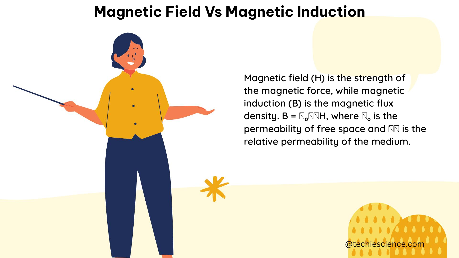
Magnetic field and magnetic induction are two closely related concepts in electromagnetism, but they have distinct physical meanings and units. The magnetic field, denoted as $\mathbf{H}$, is a measure of the magnetic force per unit charge, while magnetic induction, denoted as $\mathbf{B}$, is a measure of the magnetic flux density. Understanding the differences and relationships between these two quantities is crucial for understanding various electromagnetic phenomena and applications.

Magnetic Field ($\mathbf{H}$)

The magnetic field, $\mathbf{H}$, is a vector field that describes the magnetic force per unit charge at every point in space. It is measured in amperes per meter (A/m) in the SI system. The magnetic field is often generated by moving charges, such as current-carrying wires, and it can exert a force on other charged particles or magnetic materials.

Theorem: Ampère’s Circuital Law

Ampère’s circuital law relates the magnetic field to the electric current that generates it. The law states that the line integral of the magnetic field around a closed loop is proportional to the electric current passing through the loop:

$\oint\mathbf{H}\cdot d\mathbf{l} = \mathbf{J}$

where $\mathbf{J}$ is the current density vector.

Physics Formula: Magnetic Field of a Long Straight Wire

For a long straight wire carrying a current $I$, the magnetic field at a distance $r$ from the wire is given by:

$\mathbf{B} = \mu_0\frac{I}{2\pi r}$

where $\mu_0$ is the magnetic permeability of free space, with a value of $4\pi\times 10^{-7}$ H/m.

Physics Example: Magnetic Field of a Solenoid

Consider a solenoid with $N$ turns and a cross-sectional area $A$. If a current $I$ is passed through the solenoid, it generates a magnetic field $\mathbf{B} = \mu_0nI$, where $n = N/L$ is the number of turns per unit length.

Physics Numerical Problem: Magnetic Field of a Long Straight Wire

A long straight wire carries a current $I = 10$ A. What is the magnetic field at a distance $r = 2$ cm from the wire?

Solution:
Using Ampère’s law, we have:
$\oint\mathbf{B}\cdot d\mathbf{l} = \mu_0I$
Simplifying, we get:
$B(2\pi r) = \mu_0I$
Solving for $B$, we get:
$B = \mu_0\frac{I}{2\pi r} = 4\pi\times 10^{-7}\frac{10}{2\pi\times 0.02} = 0.1$ T

Magnetic Induction ($\mathbf{B}$)

magnetic field vs magnetic induction

Magnetic induction, also known as magnetic flux density, is denoted as $\mathbf{B}$ and is measured in Tesla (T) in the SI system. It is a measure of the magnetic flux through a given area and is related to the magnetic field through the relationship $\mathbf{B} = \mu\mathbf{H}$, where $\mu$ is the magnetic permeability of the medium.

Theorem: Faraday’s Law of Induction and Lenz’s Law

Faraday’s law of induction states that the induced electromotive force (EMF) in a conductor is proportional to the rate of change of the magnetic flux through the conductor:

$\varepsilon = -N\frac{d\Phi}{dt}$

where $\varepsilon$ is the induced EMF, $N$ is the number of turns in the coil, and $\Phi$ is the magnetic flux through the coil.

Lenz’s law states that the direction of the induced current is such that it opposes the change in the magnetic field that induced it.

Physics Formula: Relationship between Magnetic Field and Magnetic Induction

The relationship between the magnetic field $\mathbf{H}$ and the magnetic induction $\mathbf{B}$ is given by:

$\mathbf{B} = \mu\mathbf{H}$

where $\mu$ is the magnetic permeability of the medium.

Physics Example: Induced EMF in a Changing Magnetic Field

Consider a solenoid with $N$ turns and cross-sectional area $A$. If a current $I$ is passed through the solenoid, it generates a magnetic field $\mathbf{B} = \mu_0nI$, where $n = N/L$ is the number of turns per unit length. If the current is changing, then there is a changing magnetic flux through the solenoid, which induces an EMF according to Faraday’s law:

$\varepsilon = -N\frac{d\Phi}{dt} = -NA\frac{dB}{dt} = -\mu_0nAN\frac{dI}{dt}$

Physics Numerical Problem: Induced EMF in a Changing Magnetic Field

A circular coil of radius $R = 10$ cm has $N = 100$ turns and is placed in a uniform magnetic field $\mathbf{B} = 0.5$ T directed perpendicular to the plane of the coil. If the magnetic field is decreasing at a rate of $d\mathbf{B}/dt = -0.1$ T/s, what is the induced EMF in the coil?

Solution:
Using Faraday’s law, we have:
$\varepsilon = -N\frac{d\Phi}{dt} = -N\pi R^2\frac{dB}{dt} = -100\pi(0.1)^2(-0.1) = 0.314$ V

Physics Numerical Problem: Induced EMF in a Moving Coil

A rectangular coil of width $w = 5$ cm and length $l = 10$ cm is moving with a velocity $\mathbf{v} = 2$ m/s in a uniform magnetic field $\mathbf{B} = 0.5$ T directed perpendicular to the plane of the coil. What is the induced EMF in the coil?

Solution:
The magnetic flux through the coil is given by:
$\Phi = \mathbf{B}\cdot\mathbf{A} = \mathbf{B}lw$
The rate of change of the magnetic flux is:
$\frac{d\Phi}{dt} = \mathbf{B}l\frac{dw}{dt} = \mathbf{B}lv$
Using Faraday’s law, we have:
$\varepsilon = -N\frac{d\Phi}{dt} = -N\mathbf{B}lv = -N(0.5)(0.1)(2) = -0.01$ V

Figures, Data Points, Values, and Measurements

  • Magnetic field strength: $\mathbf{H}$ is measured in A/m (ampere per meter) in the SI system.
  • Magnetic induction: $\mathbf{B}$ is measured in Tesla (T) in the SI system.
  • Magnetic permeability: $\mu$ is measured in Henry per meter (H/m) in the SI system.
  • Magnetic flux: $\Phi$ is measured in Weber (Wb) in the SI system.
  • Electromotive force: $\varepsilon$ is measured in Volts (V) in the SI system.
  • Current: $I$ is measured in Amperes (A) in the SI system.
  • Charge: $q$ is measured in Coulombs (C) in the SI system.
  • Velocity: $\mathbf{v}$ is measured in meters per second (m/s) in the SI system.
  • Electric field: $\mathbf{E}$ is measured in Volts per meter (V/m) in the SI system.
  • Force: $\mathbf{F}$ is measured in Newtons (N) in the SI system.

References

  1. Magnetic flux density – Encyclopedia Magnetica. (2023-09-29). Retrieved from https://www.e-magnetica.pl/doku.php/magnetic_flux_density
  2. EC-5 MAGNETIC INDUCTION. (n.d.). Retrieved from https://www.physics.wisc.edu/instructional/phys104/EC5/EC-5.pdf
  3. Tutorial: a beginner’s guide to interpreting magnetic susceptibility … (2022-04-19). Retrieved from https://www.nature.com/articles/s42005-022-00853-y
  4. Trying to understand the difference between Magnetic induction field (B) and Magnetic Field (H). (2022-01-03). Retrieved from https://www.reddit.com/r/AskPhysics/comments/ruznt6/trying_to_understand_the_difference_between/
  5. Measuring g using magnetic induction – IOPscience. (2023-02-21). Retrieved from https://iopscience.iop.org/article/10.1088/1361-6552/acb033

Magnetic Field vs Electromagnetic Field: A Comprehensive Guide for Physics Students

magnetic field vs electromagnetic field

Magnetic fields and electromagnetic fields are closely related concepts in the realm of physics, with magnetic fields being a fundamental component of electromagnetic fields. Understanding the nuances between these two phenomena is crucial for physics students to grasp the underlying principles of electromagnetism. This comprehensive guide will delve into the technical details, formulas, and practical applications of magnetic fields and electromagnetic fields, providing a valuable resource for physics enthusiasts.

Magnetic Fields: Fundamentals and Measurements

Magnetic fields are created by the motion of electric charges, such as the flow of electric current in a wire or the spin of electrons within atoms. These fields are responsible for the magnetic forces that can attract or repel other magnetic objects. The strength of a magnetic field is typically measured in units of tesla (T) or gauss (G), with the Earth’s magnetic field having a strength of approximately 0.5 gauss (0.00005 tesla).

The strength of a magnetic field can be determined by measuring the force it exerts on a moving charge, as described by the Lorentz force equation:

$\vec{F} = q\vec{v} \times \vec{B}$

where $\vec{F}$ is the force exerted on the charge, $q$ is the charge, $\vec{v}$ is the velocity of the charge, and $\vec{B}$ is the magnetic field.

Magnetic fields can be visualized using magnetic field lines, which represent the direction and strength of the field. These field lines are typically depicted as originating from the north pole of a magnet and terminating at the south pole, forming a continuous loop.

Electromagnetic Fields: Characteristics and Measurements

magnetic field vs electromagnetic field

Electromagnetic fields, on the other hand, are created by both electric and magnetic fields, and they are responsible for electromagnetic forces. These fields can be measured in units of volts per meter (V/m) or amperes per meter (A/m), depending on the specific quantity being measured.

The strength of an electromagnetic field can be determined by measuring the force it exerts on a stationary charge, as described by Coulomb’s law:

$\vec{F} = \frac{q_1q_2}{4\pi\epsilon_0r^2}\hat{r}$

where $\vec{F}$ is the force exerted on the charge, $q_1$ and $q_2$ are the charges, $\epsilon_0$ is the permittivity of free space, $r$ is the distance between the charges, and $\hat{r}$ is the unit vector in the direction of the force.

Electromagnetic fields can be classified into different frequency ranges, including extremely low frequency (ELF) fields, radio frequency (RF) fields, and microwave fields. Each of these ranges has distinct properties and potential effects on living organisms.

Extremely Low Frequency (ELF) Fields

ELF fields have frequencies below 300 Hz and can penetrate deep into the body. These fields have been linked to various health effects, including cancer and neurological disorders.

Radio Frequency (RF) Fields

RF fields have frequencies between 3 kHz and 300 GHz and can cause heating of biological tissue. They have been associated with cancer and other health effects.

Microwave Fields

Microwave fields have frequencies between 300 MHz and 300 GHz and are used in wireless communication devices. They have been linked to cancer, neurological disorders, and reproductive problems.

Practical Applications and Examples

Magnetic fields and electromagnetic fields have numerous practical applications in various fields, including:

  1. Electricity Generation and Transmission: Magnetic fields are essential in the generation and transmission of electricity, as they are used in the operation of generators, transformers, and electric motors.

  2. Medical Imaging: Magnetic resonance imaging (MRI) and magnetic particle imaging (MPI) rely on the interaction between magnetic fields and the human body to produce detailed images for medical diagnosis and treatment.

  3. Telecommunications: Electromagnetic fields are the foundation of wireless communication technologies, such as radio, television, and cellular networks.

  4. Particle Accelerators: Powerful magnetic fields are used in particle accelerators, such as the Large Hadron Collider (LHC), to guide and control the motion of charged particles.

  5. Magnetic Levitation: Magnetic fields can be used to levitate objects, as seen in maglev trains, which use electromagnetic forces to lift and propel the train above the tracks.

Numerical Examples and Calculations

  1. Calculating the Magnetic Field Strength: Suppose a current-carrying wire has a current of 10 amperes (A) and the distance from the wire to the point of interest is 0.2 meters (m). Using the formula for the magnetic field strength around a current-carrying wire:

$B = \frac{\mu_0I}{2\pi r}$

where $\mu_0$ is the permeability of free space (4$\pi \times 10^{-7}$ T⋅m/A), $I$ is the current, and $r$ is the distance from the wire. Plugging in the values, we get:

$B = \frac{4\pi \times 10^{-7} \text{ T⋅m/A} \times 10 \text{ A}}{2\pi \times 0.2 \text{ m}} = 10^{-4} \text{ T or } 1 \text{ G}$

  1. Calculating the Electromagnetic Field Strength: Consider a power line with a voltage of 230 volts (V) and a current of 50 amperes (A). Assuming the distance from the power line is 10 meters (m), we can calculate the electromagnetic field strength using the formula:

$E = \frac{V}{r}$

$B = \frac{\mu_0I}{2\pi r}$

Plugging in the values, we get:

$E = \frac{230 \text{ V}}{10 \text{ m}} = 23 \text{ V/m}$

$B = \frac{4\pi \times 10^{-7} \text{ T⋅m/A} \times 50 \text{ A}}{2\pi \times 10 \text{ m}} = 10^{-5} \text{ T or } 0.1 \text{ G}$

The resulting electromagnetic field strength is 23 V/m and 0.1 G.

These examples demonstrate the application of the fundamental equations and formulas used to quantify magnetic fields and electromagnetic fields, providing physics students with a practical understanding of these concepts.

Conclusion

Magnetic fields and electromagnetic fields are intrinsically linked, with magnetic fields being a crucial component of electromagnetic fields. Understanding the nuances between these two phenomena, their measurements, and their practical applications is essential for physics students to grasp the underlying principles of electromagnetism. This comprehensive guide has provided a detailed exploration of the technical details, formulas, and examples related to magnetic fields and electromagnetic fields, equipping physics enthusiasts with a valuable resource for their studies and research.

References:

  1. Electromagnetic fields vs electromagnetic radiation. (2011, February 5). Physics Stack Exchange. https://physics.stackexchange.com/questions/4637/electromagnetic-fields-vs-electromagnetic-radiation
  2. Understanding electric and magnetic fields – SDGE. (n.d.). SDG&E. https://www.sdge.com/sites/default/files/final_emf_s1510006_eng.pdf
  3. Electric and Magnetic Fields – The Facts – National Grid. (n.d.). National Grid. https://www.nationalgrid.com/sites/default/files/documents/13791-Electric%20and%20Magnetic%20Fields%20-%20The%20facts.pdf
  4. Influence of Electric, Magnetic, and Electromagnetic Fields on the … (2014, April 1). National Center for Biotechnology Information. https://www.ncbi.nlm.nih.gov/pmc/articles/PMC4130204/
  5. Electric and Magnetic Fields. (n.d.). World Health Organization. https://www.who.int/peh-emf/publications/facts/fs296/en/