Tig vs Mig Welding: How to Use, What, Comparison on Strength, Body Panels, Sheet Metal, Exhaust, Cost

RK WL GMAW 240x300 1

“Tig vs Mig welding” topic will be summarize in a brief manner in this article. Tig and Mig both welding are use to prepare the weld with the help of an electric arc.

The way of using the arc is the major difference between the tig welding and mig welding. The difference between the tig welding and mig welding are discuss below,

Serial numberMIG WeldingTIG Welding
1.The meaning of the MIG is Metal Insert Gas Welding. MIG Welding also define as, Metal Active Gas Welding (MAG), Gas Metal Arc Welding (GMAW).The meaning of the TIG is Tungsten Insert Gas Welding. TIG Welding also define as, Gas Tungsten Arc Welding (GTAW).
2.In the MIG Welding method the electric arc is produce in between a workpiece metal and consumable wire electrode.In the TIG Welding method the electric arc is produce in between a workpiece metal and non consumable tungsten electrode.
3.In the MIG Welding method the electrode which is used is a type of consumable wire electrode.In the TIG Welding method the electrode which is used is a type of non consumable tungsten electrode.
4.MIG Welding is speedy welding process.TIG Welding is not too speedy welding process.
5.MIG Welding is not appropriate for various types of positions.TIG Welding is appropriate for various types of positions.
6.MIG Welding is most used in source of direct current power, constant voltage. The MID Welding method also used in alternating current and constant current.TIG Welding is most used power supply for the constant current in the method of the welding.
7.Weld deposition rate is too high for the MIG Welding method.Weld deposition rate is not too high for the TIG Welding method.
8.MIG Welding method uses in continuous wire feed.TIG Welding method not uses in continuous wire feed.
9.MIG Welding method can be applied in thick metal sheet that thickness can be vary upto 40 mm.TIG Welding method cannot be applied in thick metal sheet, it only applied for thin metal sheet that thickness can be vary upto 5 mm.
10.The materials which are used in the MIG Welding method are steels, non – ferrous materials and aluminium.The materials which are used in the TIG Welding method are non – ferrous materials such as magnesium, copper alloys and aluminium, stainless steel.
11.In the MIG Welding method high skilled operators are not needed to operate.In the TIG Welding method high skilled operators are needed to operate.
12.In the MIG Welding method application of filler metal is common.In the TIG Welding method application of filler metal is not common, when in the process filler metal is needed only that time filler metal is applied.
13.In the MIG Welding method the equipments which are used are listed below,
1. Welding power supply
2. Welding torch
3. Wire feed unit
4. Shielding gas supply
5. Welding electrode wire
In the TIG Welding method the equipments which are used are listed below,
1. Shielding gas supply
2. Constant current power supply source
3. Non consumable tungsten electrode
4. Welding torch
14.In the MIG Welding method less virtue of weld is produceIn the TIG Welding method high virtue of weld is produce
15.In the MIG Welding method filler metal is not needed. The feed electrode wire dissolves and works as a filler metal.In the TIG Welding method filler metal sometimes needed or sometimes not needed.

­­Tig vs. Mig welding strength:

TIG Welding is makes more precise and cleaner weld comparative to the MIG Welding and also others types of methods of arc welding.

TIG Welding method commonly higher and stronger in efficiency comparative to the MIG Welding method.

MIG Welding:-

MIG Welding method is a classification of Arc welding. In the method of MIG Welding a small wire is fed by a torch or tube that catches welded to the metal as the feeds the tube out the wire. MIG Welding is faster easier to operate and cheaper comparative to TIG Welding method. In automotive sector as welding process and in home projects as DIY MIG Welding method is widely used.

tig vs mig welding
Image – Gas Metal Arc Welding “Metal Insert Gas” Welding;
Image Credit – Wikipedia

TIG Welding:-

TIG Welding is faster not easier to operate and time consuming, costly and by the help of TIG welding process high quality welds is produce. In the welding robots website and industry of aerospace MIG Welding is use. In the method TIG Welding both foot by a foot pedal and hands are need to perform.

Tig vs. Mig welding body panels:

Both Metal Insert Gas Welding and Tungsten Insert Gas welding require shielding gases.

While MIG welding is useful when tackling body panels, and doesn’t require such exacting tolerances between panels, the weld is harder than in TIG welding, and leaves a higher weld, meaning heat is generated when grinding a MIG weld back (which often isn’t required at all with TIG) and the hard weld makes it tougher to work with a hammer and dolly to eliminate any warpage.

The benefits of MIG welding are that it’s way easier to weld vertically or even upside down with MIG, less operator skill is required, long welds can be made if distortion isn’t a factor, and it’s easier to learn. Benefits of TIG welding are superior quality welds, precise control of heat input, it’s spatter-free and offers low distortion and minimal cleanup. It also looks good.

Tig vs. Mig welding gloves:

The major differences in the gloves of the weldings are difference between gloves used for TIG and MIG welding.

MIG gloves generally include a thick pad at the back of the hand. This provides protection for a common MIG hand position wherein the weldor will rest the edge of the non-dominant hand against the workpiece, thumb-up.

TIG gloves, on the other hand, are generally made of much thinner, softer leather, or sometimes a mixture of leather and fire-resistant fabric.

MIG gloves also generally have a loose fit. This is handy for quickly removing them if they overheat–a glove can be flung off with one hand.

TIG gloves more snugly, and allows easy finger mobility.

Tig vs. Mig welding sheet metal:

For the both welding process of TIG and MIG sheet metal are used with the stainless steel and aluminium.

In the MIG welding thick sheet metal is used which thickness will be near about 40 mm and in TIG welding the process is done in a thin sheet metal which thickness will be around 6 mm.

Tig vs. Mig welding exhaust:

TIG can be employed with all weldable metals but is the most useful for the welding of alloys such as stainless steel and for thin materials. For this reason, a quality racing exhaust header should be welded using TIG welding.

The hand crafted quality, strength and visual appeal of TIG welding sets Cobra Exhausts apart from other brands that use MIG welding. TIG welding produces a stronger more durable weld that is generally more malleable and less brittle due to the slower cooling rate of the metals.

MIG welding should be mentioned as it is a popular welding method due to its ease of use.To weld an exhaust pipe, we recommend using a MIG welder because it works incredibly well in the welding of thinner metals. The exhaust pipes of vehicles are generally made with thinner metals so that they are lightweight when attached.

Tig vs. Mig welding cost:

The welding cost for the Tungsten Insert Gas welding more expensive than the Metal Insert Gas Welding.

Welding cost of the TIG welding is high because of TIG welding process is very slow welding process and deposition rate will also low and also need to operate this welding process expert hand, altogether tig process became costly whereas, Welding cost of the MIG welding is not too high compare to  TIG welding process.

MIG welding process is very fast welding process and deposition rate will also fast and also not need to operate expert hands to operate this welding process.

When to use Tig vs. Mig welding:

In the Metal Insert Gas Welding and Tungsten Insert Gas Welding we cannot use same gas for the both cases.

When we should to use Metal Insert Gas Welding and Tungsten Insert Gas Welding is describe below,

Metal Insert Gas Welding:-

  1. In the automotive sector and household purposes Metal Insert Gas Welding is widely used.
  2. MIG Welding can be used in very thick metal sheet the metal sheet thickness can be vary upto 40 mm.
  3. The materials which are used in the MIG Welding method are steels, non – ferrous materials.

Tungsten Insert Gas Welding:-

  1. In the pipeline welding and pipeline tig welding process is widely used and also in various industrial fields such as aviation, a sheet metal industry is also used.
  2. TIG Welding can be used in thin metal sheet the metal sheet thickness can be varying upto only 6 mm.
  3. The materials which are used in the TIG Welding method are non – ferrous materials such as magnesium, copper alloys and aluminium, stainless steel.

Tig welding vs. Mig welding roll cage:

Mainly there have three types of welder which is sufficient for the roll cages, such as stick, MIG Welder and TIG.

Metal Insert Gas welding can make acceptable welds in a roll cage, where Tungsten Insert Gas welding produce better quality roll cages and a rider could get safer ride in her/his car.

Tig vs Mig welding aluminium:

Aluminium metal is used for both methods Gas Metal Arc Welding (GMAW) and Gas Tungsten Arc Welding (GTAW).

In the industries the experts are prefer more aluminium metal in the Tungsten Insert Gas Welding process because it gives more good result on the thin and light gauge materials comparative to the Metal Insert Gas Welding. Tungsten Insert Gas welding aluminium can make more good quality welds.

Tungsten Insert Gas welding is a slower process and experts are needed to operate but can gives more precise details in the products whereas Metal Insert Gas Welding process is speedy process but not able to give so precise details in the products.

Tig vs Mig welding stainless steel:

Metal Insert Gas welding is a better option when fast welding is needed for the materials like stainless steel.

Stainless steel metal is used for both methods Gas Metal Arc Welding (GMAW) and Gas Tungsten Arc Welding (GTAW). In the industries the experts are prefer more stainless steel  metal in the Metal Insert Gas Welding process because it gives more good result on the thick and heavy gauge materials comparative to the Tungsten Insert Gas Welding.

Metal Insert Gas welding can make more good quality welds on the stainless steel materials. Metal Insert Gas welding is a very fast forward process and experts are not needed to operate but it cannot gives more precise details in the products comparative to the Tungsten Insert Gas Welding, whereas Tungsten Insert Gas Welding process is slow process and able to give so precise details in the products.

Tig welding gas vs. Mig welding gas:

In the Tig welding process longer tube is use for fuse two metals and in the mig welding is a feed wire is use which is moves constantly by the gun for creating spark then dissolve to make the weld.

The difference between Tungsten Insert Gas Welding and Metal Insert Gas Welding are describe below,

Tungsten Insert Gas Welding:-

In the Tungsten Insert Gas Welding 100% Argon gas is used. If in the Tungsten Insert Gas Weldingcarbon dioxide gas is a little amount is present then the process could not perform well because carbon dioxide reaction with electrode which is made with tungsten metal. The electrodes of the Tungsten Insert Gas Weldingare non consumable, weld fools are fed with the help of hand. TIG Welding is needed expert to operate but it could give better result than the MIG Welding.

Metal Insert Gas Welding:-

Metal Insert Gas Welding is made with Helium, Argon or Carbon dioxide, but compound of gas normally common as oxygen and argon. The astute reader always should to remember that oxygen and carbon dioxide is not the noble gases. Oxygen and carbon dioxide is deriving as semi insert gases, together with hydrogen and nitrogen. Semi insert gas helps to improve the quality of welding process but can causes too much damage.

Tig vs Mig welding machine:

TIG Welding and MIG Welding both are uses as an electric arc for make the weld.

The major difference between the tig welding and mig welding are listed below,

Diversity:-

The reason behind the widely use of mig welding in the welding process is the varieties of choices of jobs. Tig welding only can uses in the thin metal sheet which thickness is about 6 mm whereas the mig welding process can be used in the thick metal sheet that can be upto 40 mm. The materials which are used in the MIG Welding method are steels, non – ferrous materials and aluminium and the materials which are used in the TIG Welding method are non – ferrous materials such as magnesium, copper alloys and aluminium, stainless steel.

The most advantage of the mig welding method is the wire feed not only works as an electrode it also works as filler metal. As a result, the pieces which are more thick easily can be fused together without heat applying on it the entire path through. For the two different martial type of welding process mig welding easily can be work on workpiece.

Speed:-

The speed of the mig welding method is more than the tig welding method. The welding gun of the mig welding process is designed to run for a very long time without stop which making them more productive and efficient than its counterpart. In the large operations industrial fields’ high production rate is much needed in that particular case mig welding process is very useful. In automotive sector as welding process and in home projects as DIY MIG Welding method is widely used.

Cost:-

In the mig welding process the production of the product can make very quickly in a short time for this reason the mig welding gives more profit margin to any industrial field where as the tig welding process the production of the product cannot make very quickly in a short time for this reason the tig welding cannot gives profit margin as much as mig welding process.

Comfort:-

In the MIG Welding method high skilled operators are not needed to operate for this reason the operation method of the mig welding process is easier than the tig welding process whereas, in the TIG Welding method high skilled operators are needed to operate.

When to use mig welding:

In the Metal Insert Gas Welding process a consumable wire is used which is works as both as filler metal and electrode.

The welding process of mig is uses is listed below,

  1. In the automotive sector and household purposes Metal Insert Gas Welding is widely used.
  2. MIG Welding can be used in very thick metal sheet the metal sheet thickness can be vary upto 40 mm.
  3. The materials which are used in the MIG Welding method are steels, non – ferrous materials.

Application of mig welding:-

  • MIG Welding used for maximum classifications of sheet metal welding.
  • Fabrication of steel structure and pressure vessels.
  • Home improvement industry and automotive industry.
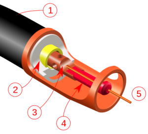
660px MIG cut away.svg
Image – GMAW torch nozzle cutaway image. (1) Torch handle, (2) Molded phenolic dielectric (shown in white) and threaded metal nut insert (yellow), (3) Shielding gas diffuser, (4) Contact tip, (5) Nozzle output face; Image Credit – Wikipedia

When to use tig welding:

In the Tungsten Insert Gas Welding process filler metal is all time not needed. When filler metal is needed in the operation only that time filler metal is used.

The welding process of tig is uses is listed below,

  • In the pipeline welding and pipeline tig welding process is widely used and also in various industrial fields such as aviation, a sheet metal industry is also used.
  • TIG Welding can be used in thin metal sheet the metal sheet thickness can be varying upto only 6 mm.
  • The materials which are used in the TIG Welding method are non – ferrous materials such as magnesium, copper alloys and aluminium, stainless steel.

Application of tig welding:-

  • TIG Welding used for automotive industry.
  • Aircraft construction and aerospace.
  • Repairing for auto body.

3+ Lathe Machine Parts: Types And Detailed Explanations About Each Parts

Lathe

This article discusses about lathe machine parts. Before discussing about different moving components used in lathe we shall discuss what is a lathe machine.

Lathe machine is known as the mother of all machines as it can produce a large variety of other machine components and its the basic industrial machine. In this article we shall discuss about different types of lathe machines, applications of lathe machine and related topics.

What is lathe machine?

Lathe can be defined as a machine tool that will rotate a workpiece around its axis rotation to perform various machining operations like cutting, sanding, drilling etc.

Through various machining operations, we can manufacture many products. The lathe machine has many working components which work in harmony to provide the desired results. The lathe has movements possible in x axis and y axis. Let us discuss more about lathe in further sections.

Lathe machine parts and functions

Lathe is an assembly of many components. These components are arranged in such a way that the user can use them simultaneously or one by one as and when needed.

The main parts of lathe are given in the section given below-

Bed

The entire lathe machine rests on the bed. The lathe machine does not have any legs or pillars on which it stands. The bed is made up of cast iron. The bed is bolted to the shop floor such that it holds all the vibrations coming out from the machining process.

Headstock is found at the end of bed. Headstock will provide the power used for rotating the spindle used in lathe machine. The headstock itself is stationary but holds the moving or rotating part of the lathe.

Spindle

Spindle collects the workpiece and provides it motion for machining process. It is simply a rotating shaft which holds the work piece while it rotates.

Leadscrew

Leadscrew is also called as power screw or translation screw. It translates motion form one form to another, it converts the rotary motion to linear motion.

Lathe machine parts diagram

We have discussed about the main parts used in lathe. But addition to these parts there are other small parts too which participate in the working of lathe machine.

The diagram of lathe machine parts is given below-

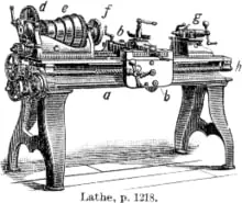
Image credits: Wikipedia

  • a- bed
  • b- carriage
  • c- headstock
  • d-back gear
  • e- cone pulley
  • f- faceplate mounted on spindle
  • g- tailstock
  • h- leadscrew

Types of lathe machines

According to the application requirements and the mode of working (automated or manual) the lathe machine is divided into following parts-

  • Automatic lathe machines – Automatic lathe machines as the name suggests are controlled using automatic cutting process. These machines are Numerically controlled or computer numeric control.
  • CNC lathes – CNC is one of the types of automatic lathe machine. It is a machine tool that performs cutting operations automatically by the computer. The operator feeds a code to the machine and the machine will keep performing its operation as per the code.
  • Ornamental– Ornamental lathe is used for ornamental turning. This type of turning involves cutting of work piece that is mounted on lathe.
  • Combination lathe – Combination lathe as the name suggests performs various machining processes such as turning, milling, cutting and drilling. These processes are performed on different lathes in conventional machines.
  • Oil field lathes– These type of lathes have very large spindle bores as well as chucks on headstock. The name oil field lathe comes from the fact that these lathes can be used in oil fields because it can handle long workpieces.
  • Turret lathe – These types of lathe are generally used for repititive production of same designs.

Uses of lathe machine

The uses of lathe machine are given in the section given below-

  • Woodworking – As the name suggests, woodworking refers to the machining of wood work pieces. Wood work pieces are mounted on the lathe and special type of tools are used for woodworking. Many kinds of furniture items are produced using the help of woodworking lathe.
  • Duplicating – We can copy or duplicate a shape using a special type of lathe known as copy lathe. This type of lathe is used for replicating objects.
  • Pattern making– Pattern making is also a type of duplicating process. Patterns are made for making moulds that are used in casting process.
  • Metal working – Metal working is simple metal machining process in which the metal surfaces are chipped off to make the desired shapes.
  • Metal spinning– In metal spinning a disc of metal is rotated around a center and a tool that is kept stationary cuts the metal. This is also called as metal turning.
  • Glass working– Glass working as the name suggests is the technique in which various methods are used to cut and make designs from glass.
  • Ornamental turning– In ornamental turning, there is facility to cut the workpiece mounted on the lathe.
  • Reducing– In reducing process, the radius of the workpiece is reduced from the original dimension to the desired dimension. In the operation the workpiece and the cutting tool are kept perpendicular to each other.
  • Watchmaking– Watchmaking is a process of making watches. In watchmaking lathes, the tools are designed in such a way that we can manufacture watch parts on it.

Accessories used on lathes

Accessories used in lathes improve the performance of lathe. These accessories make it easy and convenient for the althe operator to operate the machine.

The accessories used in lathe machine are given in the section below-

  • Faceplate– Faceplate is a holding accessory in a lathe. The faceplate can be used to hold both wood and metal workpieces.
  • Four jaw/three jaw chuck- The chucks are used for clamping the work pieces. Three jaw chucks are commonly used for circular workpiece whereas uneven workpieces can be worked upon four jaw chucks. In four jaw chucks, each jaw needs to be fit manually whereas in three jaw chuck all the three jaws move together.
  • Collet– Collet is also used for holding circular objects by making a collar around it. This collar exerts a strong clamping force on the object.
  • Dead center- A dead center is used to support the workpiece at either the fixed part or rotating part in the machine.

Efficiency Of Internal Combustion Engine: What, How, Different Types and Facts

Carnot cycle pV diagram.svg

In this article we shall discuss about the topic- Efficiency of internal combustion engine. Internal combustion engines are commonly used in locomotives to run them.

The internal combustion engines or IC engines use the thermal energy from burnt fuel and gets it converted to mechanical energy. The speed of locomotives depend on how fast the combustion cycle is repeating itself inside the engine. In this article we shall study about internal combustion engines in detail.

What is internal combustion engine?

Internal combustion engines are heat engines inside which the fuel is combusted with the help of an oxidizer. The resulting thermal energy is converted to mechanical energy by pushing the piston to the bottom most part of the cylinder

The piston moves back and forth performing a reciprocating motion. The reciprocating motion of piston is directed to the crankshaft. The crankshaft starts rotating as a result of which the wheels also rotating. We shall study more about internal combustion engines in detail in further sections of this article.

How does an internal combustion engine work?

Internal engines work by converting the thermal energy, produced after combusting fuel in the presence of an oxidizer, to mechanical energy. When the piston is at top dead center, fuel is burnt as a result of which some amount of thermal energy is released.

This energy pushes the piston to the bottom dead center. The piston moves to the top dead center again due to inertia, this time the exhaust gases are expelled out from the exit valve. The piston is connected to a crank through connecting rod which converts the reciprocating motion of piston to rotary motion.

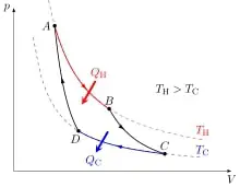
Carnot cycle pV diagram.svg
Image: Carnot Cycle

Image credits: Cristian QuinzacaraCarnot cycle pV diagramCC BY-SA 4.0

What is the efficiency of internal combustion engine?

We now know the working of intrernal combustion engine works. We know that internal engine can produce its own work.

Now we shall discuss about the efficiency of an internal efficiency. It is defined as the amount of work that the engine has produced to the heat input to the engine.  

Mathematically, efficiency is given as-

Input

Heat efficiency of internal combustion engine

Heat efficiency of internal combustion engine is the ratio of useful heat to the total heat input given to the system.

The heat source provides the heat to the heat engine and a heat sink absorb all the waste heat from the engine. The useful heat is used as the work output from the engine. The heat efficiency of an internal combustion engine is given in the section given below-

Input

Volumetric efficiency of an internal combustion engine

The volume of the cylinder is called as the swept volume which is the maximum volume of air fuel mixture that can be taken in.

Volumetric efficiency is the ratio of total air fuel mixture taken inside the cylinder to the total volume of the cylinder or the swept volume. Mathematically, the volumetric efficiency of an internal combustion engine is given in the section below-

V %7Bswept%7D

Overall efficiency of internal combustion engine

Overall efficiency of any heat engine takes into account all types of efficiencies namely, thermal efficiency, mechanical efficiency, volumetric efficiency etc.

Mathematically, the overall efficiency of internal combustion engine is –

Input

What is mechanical efficiency of an internal combustion engine?

Mechanical efficiency is the efficiency with which the mechanical components inside the internal combustion engine work.

The mechanical components include piston, valves, piston pin cylinder etc. The engine works when these mechanical components work in harmony with each other. Mechanical efficiency is a ratio between two things, they are work output and work input.

What is the maximum efficiency of internal combustion engine?

Different internal combustion engines have different efficiencies. The efficiencies depend on the mechanical efficiency, type of fuel used, type of engine etc.

The most efficient internal combustion engines have an efficiency of 50% but the engines that are allowed on road have efficiencies between 20 to 30 percent. Combustion engines are not as efficient as we though them to be as the energy conversion rate is very low.

How to calculate the efficiency of internal combustion engine?

In above sections we saw the formula of calculating efficiency of internal combustion engine. In those sections we did not discuss about how to find the quantities used in that formula.

The work done is defined as the net useful heat taken from the heat input. So the net work can be found simply by subtracting Heat input and heat output. The difference between the two will give us the net work output. When we divide the work output by heat input swe get the value of efficiency. We have already discussed the formula in above sections.

Efficiency of internal combustion engine vs electric motor

We have already discussed about the maximum efficiencies of internal combustion engines. The electric motor vehicles do not burn fuel to run.

Electric motors on the other hand have higher efficiency than combustion engines. The energy conversion rate of electric motor is 85 % . So we can say that the electric motors have an efficiency of around 80%-85% whereas the maximum efficiency of an internal combustion engine can go nearly up to 50%.

Efficiency of internal combustion engine vs gas turbine

Gas turbines are mechanical devices that convert heat energy from steam to mechanical energy. The mechanical energy will be converted then to electrical energy which is done with the help of a generator.

Gas turbines have an efficiency of around 35-40%. That is more than most of the internal combustion engines. But we do not use gas turbines in locomotives because of the size. Internal combustion engines are compact in size whereas the gas turbines are huge and are used in applications with high speeds.

How to increase efficiency of internal combustion engine?

To increase the efficiency of internal combustion engines we use the following methods-

  • Lower heat rejection
  • High compression ratio
  • Using a lean fuel mixture
  • Running the engine at optimum conditions

Why are gas turbines not used in vehicles if they have higher efficiency?

The efficiency of gas turbines may be higher. We have discussed the numbers in the above sections already. But the reason why they are not used in vehicles is the size of a turbine.

The size of a gas turbine is very large. This is why turbines are used in aeroplanes and not in vehicles. The gas turbines are used where the application deals with high speed. Internal combustion engines are compact in size hence they are used in vehicles and gas turbines are not.

Lathe Machine Working: Detailed  Explainations  about Each Parts

Lathe 150x150 1

In this article the topic of “Lathe machine working” about every parts is discuss in a brief manner. The lathe is actually a machine tool that is mainly used to remove excess amount of material from the face workpiece.

Lathe is a machine tool. The lathe which about an axis is rotate a workpiece to carry out various types of functions such as facing, drilling, cutting, turning, deformation, knurling, sanding, with the help of tools which is exerted to the workpiece thus a needed shaped object can get.

The parts of the lathe machine:-

Lathe machine working with detailed explanations about each part:-

The each parts of the lathe working with detailed explanations is discuss below,

Headstock:-

In the machine tool of the lathe the part plays an important role is Headstock. The headstock permanently mounted in the inner guide ways of the bed in the left side.

Headstock contains some parts such as back bear drive, main spindle, a chuck which is fitted at the spindle nose and also all the gear drive.

lathe machine working
Image – A metalworking lathe from 1911, showing component parts:
a: bed
b: carriage (with cross-slide and tool post)
c: headstock
d: back gear (other gear train nearby drives lead screw)
e: cone pulley for a belt drive from an external power source
f: faceplate mounted on spindle
g: tailstock
h: leadscrew;

Image Credit – Wikipedia

Function:-

The work of the headstock is to carry the whole mechanism or pegs of the lathe machine tool which is hold the strings at the top of the instrument. At the tail of the lathe the strings of the string are usually carry by the bridge or tailpiece.

Accessories:-

The accessories carried by the headstock spindle is listed below,

  1. Three jaw chuck
  2. Magnetic chuck
  3. Four jaw chuck
  4. Collect chuck
  5. Faceplate
  6. Lathe center
  7. Lathe dog

Bed:-

The bed of the machine tool of the lathe forms the base.

Bed of the lathe is made with cast iron. The top surface of the bed is machined precisely and accurately.

The bed of the lathe is bolted to the ground.

The bed is placed in the legs of the machine tool of the lathe.

Function:-

The base of the bed for a machine tool of lathe is robust and by the help of bed headstock is connected and allows and tailstock the carriage to be moved freely parallel by the axis of the spindle.

Support is given by the bed of the parts of the lathe machine tool such as, carriage, tailstock, feed mechanism and many more.

Deflection made by the cutting force which is prevent by the bed.

A bed is rigid and has enough good capacity to take vibration of the machine tool

Tail stock:-

The body of the tailstock is made with cast iron.

The structure of the tailstock is house and bored the spindle of the tailstock.

Tailstock is placed on the right side exactly above the bed of the machine tool of lathe.

Function:-

The tail stock grips the tool so that the tools can perform different types of operations such as tapping, drilling, reaming and many more.

The tail stock support the longer end o the job for minimize and holding its sagging.

Main spindle:-

The main spindle is a shaft which is hollow cylindrical and in between the main spindle long job easily can go through.

The design of the main spindle is so good thus the cutting tool of the lathe machine tool thus thrust cannot deflect the spindle.

Carriage:-

The carriage of the lathe machine tool is used to guide, support and also feed against the workpiece when the machining is done.

The parts which are carrying by the carriage are listed below,

  1. Apron
  2. Cross – slide
  3. Saddle
  4. Toolpost
  5. Compound rest

The three movements which are provide by the carriage to the workpiece are listed below,

  1. Longitudinal feed through carriage movement
  2. Cross feed through slide movement
  3. Angular feed through slide movement

Function:-

The carriage controls and moves the cutting tool.

During the operation the carriage provide a rigid support to the tool.

Transform the power from the feed rod to the cutting tool by the apron mechanism for longitudinal cross – feeding.

Lathe machine operations:

The operations is done by the lathe machine is listed below,

Facing:-

On the lathe machine tool facing is acts as a facing tool for cutting a flat area perpendicular to the job’s rotational axis. A facing tool is situated into a tool holder that is rest on the carriage of the machine tool of the lathe.

After that the tool will be feed perpendicularly to the area’s rotational axis as it rotates in the jaw of the chuck. The user has the option for hand feeding the machine tool of the lathe while facing or the power feed option can be use. For getting a more smooth surface, the power feed option is uses to appeasement due to a feed rate which stays at constant. Factors which are affect the effectiveness and quality of facing actions on the lathe machine tool such as, cutter size, speeds and feeds, material hardness, and also how the section is clamped down.

Centering:-

Centering is a process of gripping the job into chuck of the machine tool of the lathe, face place and drive plate on the center portion of the lathe machine. The process of the center is needed for the workpiece concentric to the center for the machining into the cylindrical shaped.

Work to be turned in the machine tool of the lathe may be either held in the centres; or fastened in a chuck, or clamped to the faceplate. The work which is to be faced or turned true with a finished hole is held either no a mandrel between centres, or on a special mandrel the shank of which fits the spindle. In the case of work to be held between the live and dead centres of the lathe, first sixty degree counter-sink holes (which fit the sixty degree lathe centres) are drilled and reamed in both ends of the work.

The work is fitted in the centres and is usually driven from the face-plate by means of a dog which is securely clamped to it on the live-centre end. The work thus turns with the live centre which acts both as a support and a bearing.

Grooving:-

Grooving is an operation by which diameter is reduced of a workpiece in a very narrow space. With the help of groove tool the operation grooving is done. Grooving tool is almost same to the parting tool. It is frequently done at the part of the end of a thread or neighbouring to a shoulder to parting a small margin.

Groove
Image – Groove on a cylinder; Image Credit – Wikipedia

Chamfering:-

Chamfering is an operation which is done in the end section of the bolt and the end section of the shaft. In the chamfering operation on the workpiece which is mainly in cylindrical shaped get a bevelled area. By the help of chamfering damage can be avoided in the edges of the sharp and also protect the operation getting hurt during the other operation. The chamfering operation helps to screw the nut upon the bolt.

Knurling:-

Knurling is an operation by which in a workpiece diamond shape is obtained for the purpose of the gripping. Knurling operation is done for holding better into the surface of the workpiece when operation done by hand. By the using a knurling tool the operation of knurling is done. The knurling tool carried of a set of hardening steel roller and rigidly holds the toolpost.

Boring:-

Most of the turning methods that appear with external turning are also to be found in boring. With external turning, the length of the workpiece does not affect the tool overhang and the size of the toolholder can be chosen so that it withstands the forces and stresses that arise during the operation. However, with internal turning, or boring, the choice of tool is very much restricted by the workpiece’s hole diameter and length.

A general rule, which applies to all machining, is to minimize the tool overhang to obtain the best possible stability and thereby accuracy. With boring the depth of the hole determines the overhang. The stability is increased when a larger tool diameter is used, but even then the possibilities are limited since the space allowed by the diameter of the hole in the workpiece must be taken into consideration for chip evacuation and radial movements.

The other operations which are done by the lathe machine named are also listed below,

  • Rough turning
  • Finish turning
  • Recessing
  • Reaming by occupying the cutting tool by the help of taper upon the short length
  • Boring (internal turning) taper and straight
  • Cutting helical threads
  • Forming internal and external
  • Taper turning
  • Axial drilling
  • Shouldering

Lathe machine specification:

The specifications of lathe machine are listed below,

  • Lead screw pitch
  • Maximum diameter of the bar
  • The length by the centers of the two
  • Height of the center
  • Tailstock sleeve travel
  • Motor horse power and Revolution per minute
  • Shipping dimension (Weight * Length * height * Width)
  • Metric thread pitches
  • Swing diameter on the bed

Click to Read more on 10+ Rack And Pinion Examples: Types, Working, Parts.

Specific Humidity vs Relative Humidity: Relationship, Differences and Facts

In this article the topic is “Specific humidity vs. relative humidity” and specific humidity vs. relative humidity related facts and relationship will be prate in a brief manner.

Specific humidity is a physical parameter by which express as the ratio between the mass of the water vapor and net moist mass of the air parcel. Relative humidity derives as in a particular temperature the portion to reveal a present state of absolute humidity comparative to a maximum humidity.

How to determine the specific humidity to relative humidity:

Determination of the specific humidity to relative humidity is discuss below,

Relative humidity can be express as e/e0 and derive as, the proportion of the vapor pressure to the pressure of the saturation vapour. In other word the proportion of mass compound proportions of vapor of water at practical and saturation values and express as, w/ws. If the value of the specific humidity is know then compound mixing proportion of the vapor of water in air can be written as,

q ≡ mv/mv+md = w/w+1 ≈ w

Relative humidity can be derive as, the proportion of the vapor of water compound proportion to vapor of water compound proportion w/ws \\frac{w}{w_s}

Where,

ws ≡ mvs/md = esRd/Rv (p-es) ≈ 0.622es/p

And from the Clausius – Clapeyron equation we can write,

gif.latex?e s%20%28T%29%20%3D%20e s 0%20exp%20%5B%28%5Cfrac%7BL v%28T%29%7D%7BR v%7D%29%28%5Cfrac%7B1%7D%7BT 0%7D%20 %20%5Cfrac%7B1%7D%7BT%7D%29%5D%20%5Capprox%20611%20exp%20%28%5Cfrac%7B17.67%28T%20 %20T 0%29%7D%7BT%20 %2029

When the value of w and w_s is obtained in that case we can write,

RH = 100w/ws ≈ 0.263pq[exp(17.67(T-T0)/T-29.65)]

We also can calculate the value using this equation,

RH = 100e/es

But with this equation problems can be arise just because q is not straightforward.

The variables are used in this equation are given below,

q = Specific humidity or mass compound proportion of the vapor of the water to total amount of air and it is dimensionless

T = Temperature and unit is Kelvin

mv= Specific mass of the vapor of the water and unit is kilogram

md = Specific mass of the air which is dry and unit is kilogram

w = Mass compound proportion of the vapor of the air which is dry and it is dimensionless

mvs = Specific mass of the vapor of the water at equilibrium and unit is kilogram

ws= Mass compound proportion of the vapor of the air which is dry at equilibrium and it is dimensionless

[ Lv= Specific enthalpy for the vaporization and unit is Joule per kilogram per Kelvin

Rd= Specific gas constant of the air which is dry and unit is Joule per kilogram per Kelvin

Rv= Specific gas constant of the vapor of the water and unit is Joule per kilogram per Kelvin

es= Saturation pressure of the vapor at T and unit is Pascal

es0= Saturation pressure of the vapor at T0 unit is Pascal

p = Pressure and unit is Pascal

Specific humidity vs relative humidity
Image – Thermo hygrometer displaying temperature and relative humidity; Image Credit – Wikipedia

Define major points for the specific humidity vs relative humidity:

Humidity is the amount of vapor of the water which is present in the air. Humidity can be derive as, relative value, specific value and absolute value.

The difference between specific humidity and relative humidity is describe below,

When the value of relative humidity is known of the air which is most and the density of the vapor of the water, and the density of the vapor of the air in that particular case the specific humidity can be written as,

x = 0.622φρws/ρ-ρws x 100%

Where,

x = Specific humidity of the vapor of the air compound

φ= Relative humidity

ρws= Densisity of the vapor of the water and unit is kilogram per cubic meter

ρ= Density of the vapor of the humid air and unit is kilogram per cubic meter

What is the specific humidity?

The unit of the specific humidity is most useful unit of the dimension of the humidity.

Specific humidity can be derive as, the total mass of the vapor of the water in a unit mass o the air of the moist. In air conditioning system the specific humidity can be express as, grains per pound and usually the specific humidity can be express as vapor of the air in kilogram.

The equation of the specific humidity is,

SH = 0.622 x P/P-Pw x 100%

Where,

SH = Specific humidity or mass compound proportion of the vapor of the water to total amount of air and it is dimensionless

P = Pressure and unit is Pascal

Pw= Pressure pressure of the vapor of the water and unit is Pascal

As temperature decreases, the amount of water vapor needed to reach saturation also decreases and as temperature increases, the amount of water vapor needed to reach saturation also increases. As the temperature of a parcel of air becomes lower it will eventually reach the point of saturation without adding or losing water mass.

How to calculate specific humidity with temperature, relative humidity and pressure?

Determine the specific humidity with temperature, relative humidity and pressure is describe below,

If the equation the value of Relative humidity is given in that case the value of temperature and pressure easily can be calculate using this equation,

RH = e/es

w = eRd/Rv(p-e)

And,

q = w/w+1

After that we can estimate the value of specific humidity which is express as q. The value of specific humidity can be estimate using this equation,

gif

From the equation of e = RH \\times e_s we can estimate the value of e and then value of the e is plug into the equation for w. Then putting the value of the result into the equation for q.

The variables are used in this equation are given below,

q = Specific humidity or mass compound proportion of the vapor of the water to total amount of air and it is dimensionless

w = Mass compound proportion of the vapor of the air which is dry and it is dimensionless

es= Saturation pressure of the vapor at T and unit is Pascal

es0= Saturation pressure of the vapor at T0unit is Pascal

Rd= Specific gas constant of the air which is dry and unit is Joule per kilogram per Kelvin

Rv= Specific gas constant of the vapor of the water and unit is Joule per kilogram per Kelvin

p = Pressure and unit is Pascal

Lv= Specific enthalpy for the vaporization and unit is Joule per kilogram per Kelvin

T = Temperature and unit is Kelvin

T0= Reference temperature and unit is Kelvin

393px Umidaderelativa
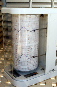
Image – A hygrothermograph for humidity and temperature recording; Image Credit – Wikipedia

How to find specific humidity from dew point?

Dew point can be derive as in this way the fixed temperature at which vapor of the water start to condense in to water.

Finding the specific humidity from dew point is given below,

gif

The variables are used in this equation are given below,

Ts= Dew point

b = Magnus coefficient

a = Magnus coefficient

T = Temperature

RH = Relative humidity of the air

Dewpoint
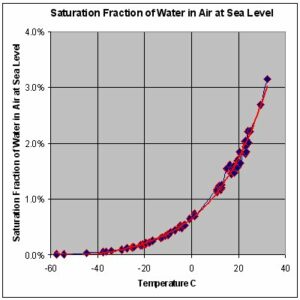
Image – This graph shows the maximum percentage, by mass, of water vapor that air at sea-level pressure across a range of temperatures can contain. For a lower ambient pressure, a curve has to be drawn above the current curve. A higher ambient pressure yields a curve under the current curve;
Image Credit – Wikipedia

How to calculate maximum specific humidity?

The calculation of the maximum specific humidity is discuss below,

At the beginning of the process of calculation of the specific humidity need to measure the net amount of pressure for the air.

In the next step of the calculation of the specific humidity need to determine the partial pressure for the vapor of the water.

In final step using the specific humidity equation put the value of pressure for the air and partial pressure for the vapor of the water and determines the value.

The equation of the specific humidity is,

SH = 0.622 x P/P-Pw x 100%

Where,

SH = Specific humidity or mass compound proportion of the vapor of the water to total amount of air and it is dimensionless

P = Pressure and unit is Pascal

Pw= Pressure pressure of the vapor of the water and unit is Pascal

Frequent asked question:-

Question: – Write down the conditions which are most preferred for the dew points.

Answer: – The conditions which are most prefer for the dew points is listed below,

  1. Clear sky at the night time particularly a day after warm
  2. Little amount of vapor of the water at the higher surrounding
  3. If no strong wind is not present in the night time means calm night
  4. In the lower tier of the higher humidity

Question: – Write down the structures which are most preferred for the dew points.

Answer: – The structures which are most preferred for the dew points are listed below,

  • Good radiators
  • Poor thermal conductivity
  • Exposed and thin matters such as petals, grass blades and leaves
  • Well isolated from the surface

Relative Humidity And Temperature: Relationship, Graph, Formula, Chart

220px HS Wasserdampf engl 1

This article discusses the relationship between relative humidity and temperature. Humidity can be defined as the presence of water droplets in air, making it an air-water mixture.

The humid air is moist in nature. In this article we shall study about the effect of temperature on relative humidity. Simply put, relative humidity and temperature are inversely proportional to each other. The reason behind this is discussed in the later sections of this article.

What is relative humidity?

Relative humidity is the ratio of amount of water present in the air water mixture to the maximum of water that can be present in the air water mixture. It represents the relative amount of vapour that can be added up till saturation.

In simple words we can say that it is the measure of how much amount of water is present inside the air water mixture relative to the maximum to the amount of water that can be added to the mixture. Let us see the formula of relative humidity in next section to make things more clear.

Relative humidity formula

We have discussed the definition of relative humidity in the above section. To make the meaning more clear let us have a look at the formula of relative humidity.

The formula of relative humidity is given in the section below-

φ = Pv/Ps

where,

phi is the realative humidity

Pv is the partial pressure of vapour

Ps is the saturation pressure

What is specific humidity?

Specific humidity is different from relative humidity. It is defined as the ratio of amount of water present in the air water mixture to the total mass of the air water mixture.

The formula to calculate specific humidity is given in the section below-

ω = mv/ma

Where,

omega is the specific humidity

mv is the mass of vapour

ma is the mass of air water vapour mixture

Relative humidity and temperature relationship

We all know that water evaporates in the presence of heat or higher temperatures. This phenomenon can be applied to define the relationship between temperature and relative humidity.

When we say that both are inversely proportional to each other, it means one value increases and other decreases. In this case when the temperature increases the value of relative humidity will decrease. And vice versa. The reason being that warm air has more capacity to hold moisture hence the denominator increases. If the air becomes dry then the value of relative humidity also decreases. When the temperature drops, the air becomes wet and hence the value of relative humidity also increases.

Relative humidity and temperature graph

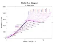
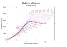
The graph that represents relative humidity and temperature is called as Mollier chart or Mollier diagram. There are many other quantities represented as well.

In the chart we can see that relative humidity curve has a negative slope when we go from right to left. Right to left means the value of temperature decreases. When we go from left to right that is when we increase the temperature, the value of relative humidity also increases.

Relative humidity and temperature formula

To derive a formula between temperature and relative humidity, we use many concepts from thermodynamics mainly- ideal gas law, thermodynamics law, Psychrometrics and conservation of mass.

Using above concepts we get the following formula (The formula is used to calculate the dew point temperature of the mixture)-

Tdp = 4030 (Tdb+235)/4030 – (Tdb+235)lnRH – 235

where,

Tdp is the Dew point temperature

Tdb is the dry bulb temperature

RH is the relative humidity

Relative humidity and temperature chart

We have already discussed about Mollier chart in above section. The Mollier chart represents relationship between various psychrometric properties and dry bulb temperature.

The dry bulb temperature is represented on the x axis or horizontal axis. The value of dry bulb temperature will increase when we move from left to right. The value of relative humidity decreases as we move from left to right or when the dry bulb temperature increases. The reason being that water droplets are evaporated as the temperature is increased. The increased temperature results in dryer air.

relative humidity and temperature
Image: Mollier Diagram

Image credits: Markus SchweissHS-Wasserdampf englCC BY-SA 3.0

Factors affecting relative humidity?

Relative humidity is mainly affected by the temperature and geopgraphic locations. We have already discussed about the effect of temperature on relative humidity. 

The air is wet when temperature is lesser and when the temperature is more the air will become dry as the capacity of air to hold moisture increases. Geographic locations also affect relative humidity. For example, near coastal areas the humidity levels are very high due to evaporation. And places far away from water bodies have lower humidity levels.

What is psychrometry?

Psychrometry is the study of proerties of various properties of air and water vapour mixture. These properties may include specific humidity, dew point temperature, wet bulb temeprature, relative humidity etc.

This branch of thermodynamics holds important applications in refrigeration and air conditioning industry. It is very important to maintain the humidity levels at certain places. Excessive humidity levels can lead to severe damages and failures. Similarly lack of humidity can also harm the system in consideration.

What is wet bulb temperature?

 The name itself suggests that wet bulb temperature is related to wetness of the bulb. It is the temperature that thermometer shows when its bulb is coveres with a wet cloth.  

Due to the wet cloth, the temperature slightly decreases due to heat absorption by water molecules on the cloth. These water molecules are responsible for an increase in relative humidity levels in the system. We should note that wet bulb temperature is always lesser than or equal to dry bulb temperature. The dry bulb and wet bulb temperature are equal at saturation.

What is Mollier diagram?

Mollier diagram is a graphical representation of various psychrometric properties changing with dry bulb temperature.

The dry bulb temperature is represented on the horizontal axis. Other properties are broadly plotted in the graph. Such as specific humidity is plotted as horizontal lines and relative humidity lines are plotted slantly such that the lines bank towards left.

How To Control Relative Humidity: Increase, Decrease In Different Circumstances

220px HS Wasserdampf engl

Controlling relative humidity is essential for maintaining a comfortable and healthy indoor environment. High humidity can lead to mold growth, musty odors, and respiratory issues, while low humidity can cause dry skin, static electricity, and discomfort. To control relative humidity, several methods can be employed, such as using dehumidifiers to remove excess moisture from the air, ensuring proper ventilation to allow fresh air circulation, and sealing any air leaks to prevent moisture infiltration. Additionally, using air conditioners and fans can help regulate humidity levels. By implementing these strategies, you can create a more pleasant and healthier living space.

Key Takeaways

Method Description
Dehumidifiers Removes excess moisture from the air
Ventilation Allows fresh air circulation
Sealing air leaks Prevents moisture infiltration
Air conditioners and fans Regulate humidity levels

Understanding the Impact of Relative Humidity

Relative humidity is a crucial factor that affects our daily lives in various ways. It refers to the amount of moisture present in the air compared to the maximum amount the air can hold at a specific temperature. Understanding the impact of relative humidity is essential for maintaining comfortable and healthy living environments, as well as for various industrial and agricultural applications.

When is the Relative Humidity Lowest?

220px HS Wasserdampf engl
Mollier

The relative humidity is typically lowest during the hottest part of the day when the temperature is at its peak. This occurs because warm air has the ability to hold more moisture than cool air. As the temperature rises, the air’s capacity to hold moisture increases, resulting in a lower relative humidity. Low relative humidity levels can have several effects, such as increased evaporation rates, accelerated moisture absorption, and potential discomfort due to dryness.

When is the Relative Humidity Highest?

Conversely, the relative humidity is usually highest during the coolest part of the day or in the early morning when the temperature is lower. Cooler air has a lower capacity to hold moisture, leading to a higher relative humidity. High relative humidity levels can contribute to a range of issues, including condensation, mold growth, and a general feeling of dampness. It is important to control humidity levels in order to prevent these problems and maintain a healthy indoor environment.

Does Relative Humidity Change with Temperature?

Yes, relative humidity changes with temperature. As the temperature increases, the air’s capacity to hold moisture also increases. This means that even if the amount of moisture in the air remains constant, the relative humidity will decrease as the temperature rises. Similarly, as the temperature decreases, the air’s capacity to hold moisture decreases, resulting in an increase in relative humidity.

Does Relative Humidity Decrease with Temperature?

No, relative humidity does not decrease with temperature. In fact, as mentioned earlier, relative humidity increases as the temperature decreases. This is because cooler air has a lower capacity to hold moisture, causing the relative humidity to rise. It is important to note that while the relative humidity may increase with decreasing temperature, the actual amount of moisture in the air may remain the same or decrease.

Does Relative Humidity Increase When Temperature Decreases?

Yes, relative humidity increases when the temperature decreases. As the temperature drops, the air’s capacity to hold moisture decreases, leading to a higher relative humidity. This can be observed during colder seasons or in regions with cooler climates. It is crucial to monitor and control humidity levels, especially in environments where temperature fluctuations are common, to prevent issues such as condensation, mold growth, and discomfort.

Understanding the impact of relative humidity is vital for maintaining optimal indoor air quality, preventing moisture-related problems, and ensuring the well-being of individuals. Various humidity control methods, such as the use of dehumidifiers, humidifiers, HVAC systems, and ventilation, can help regulate and maintain humidity levels in homes, greenhouses, basements, and other spaces. Monitoring relative humidity using hygrometers or humidity sensors is essential for effective humidity control. Additionally, moisture absorption materials and desiccants can aid in controlling dampness and moisture levels.

Remember, relative humidity is influenced by temperature, and both factors play a significant role in creating a comfortable and healthy environment. By understanding and managing relative humidity, we can create spaces that are conducive to our well-being and prevent potential issues caused by excessive moisture or dryness.

How to Control Relative Humidity

Relative humidity refers to the amount of moisture present in the air compared to the maximum amount the air can hold at a specific temperature. Controlling relative humidity is important for maintaining comfortable and healthy indoor environments. In this article, we will explore various methods to control relative humidity and ensure optimal moisture levels in different settings.

How to Increase Relative Humidity

There are several ways to increase relative humidity in a space. One effective method is to use humidifiers. Humidifiers are devices that add moisture to the air, increasing the humidity levels. They are commonly used in homes, offices, and other indoor environments to combat dry air and improve indoor air quality. Humidifiers come in different types, such as evaporative, ultrasonic, and steam humidifiers, each with its own advantages and considerations.

Another way to increase relative humidity is by utilizing moisture-absorbing materials, such as wet towels or bowls of water placed strategically in the room. These materials release moisture into the air through evaporation, raising the humidity levels. Additionally, proper ventilation can help increase relative humidity by preventing excessive air exchange with drier outdoor air.

How to Reduce Relative Humidity

On the other hand, if you need to reduce relative humidity in a space, there are several methods you can employ. One effective approach is to use dehumidifiers. Dehumidifiers are devices that remove excess moisture from the air, lowering the humidity levels. They are commonly used in areas with high humidity or dampness, such as basements, bathrooms, and laundry rooms. Dehumidifiers work by condensing the moisture in the air and collecting it in a reservoir or draining it directly.

Proper ventilation is another way to reduce relative humidity. By increasing the airflow in a space, you can help remove excess moisture and maintain lower humidity levels. This can be achieved through the use of fans, opening windows, or utilizing HVAC systems with appropriate settings.

How to Control High Relative Humidity

Controlling high relative humidity is crucial to prevent issues such as mold growth, condensation, and discomfort. In addition to using dehumidifiers and ventilation methods mentioned earlier, it is important to identify and address the source of excess moisture. This may involve fixing leaks, improving insulation, or addressing any other factors contributing to high humidity levels.

Monitoring relative humidity using hygrometers or humidity sensors is also essential for effective control. These devices measure the moisture content in the air and provide valuable information for adjusting humidity control devices and strategies accordingly.

How to Control Humidity and Temperature

Humidity and temperature often go hand in hand when it comes to creating a comfortable indoor environment. HVAC systems play a significant role in controlling both humidity and temperature. These systems can be equipped with humidifiers and dehumidifiers to regulate moisture levels, while also maintaining desired temperature settings. By integrating humidity control into HVAC systems, you can achieve optimal comfort and indoor air quality.

How to Control Air Humidity

In certain specialized environments like greenhouses, precise control of air humidity is essential for plant growth and health. Humidity control systems in greenhouses often involve a combination of ventilation, misting systems, and evaporative cooling techniques. These systems help maintain the ideal humidity levels required for specific plants and crops, ensuring optimal growth conditions.

Controlling Relative Humidity in Different Environments

Maintaining the right level of humidity is crucial in various environments, as it directly impacts the comfort, health, and overall quality of the space. Whether it’s a room, clean room, HVAC system, greenhouse, or warehouse, controlling relative humidity is essential to prevent issues such as mold growth, condensation, and discomfort. In this article, we will explore different methods and techniques to effectively control relative humidity in various environments.

How to Control Relative Humidity in a Room

Controlling relative humidity in a room is essential for creating a comfortable and healthy indoor environment. There are several methods to achieve this:

  1. Use a Dehumidifier: Dehumidifiers are devices that remove excess moisture from the air, helping to reduce humidity levels. They work by drawing in humid air, cooling it to condense the moisture, and then releasing the drier air back into the room.

  2. Utilize Humidifiers: In dry environments, humidifiers can be used to increase the humidity levels. These devices add moisture to the air, creating a more comfortable atmosphere, especially during winter months when indoor air tends to be drier.

  3. Proper Ventilation: Good ventilation is crucial for controlling humidity levels in a room. Opening windows or using exhaust fans can help remove excess moisture and improve air circulation.

  4. Monitor with Hygrometers: Hygrometers are instruments used to measure relative humidity. By regularly monitoring the humidity levels in a room, you can adjust your humidity control methods accordingly.

How to Control Temperature and Humidity in a Room

Controlling both temperature and humidity in a room is important for maintaining a comfortable and healthy environment. Here are some methods to achieve this:

  1. Use HVAC Systems: HVAC (Heating, Ventilation, and Air Conditioning) systems are designed to regulate both temperature and humidity. They can cool or heat the air while also controlling moisture levels, ensuring optimal comfort.

  2. Install Humidity Sensors: Humidity sensors can be integrated into HVAC systems to monitor and regulate humidity levels automatically. These sensors detect changes in moisture and adjust the system accordingly to maintain the desired humidity.

  3. Proper Insulation: Insulating a room effectively can help control both temperature and humidity. Insulation helps prevent heat transfer and minimize moisture infiltration, creating a more stable indoor environment.

How to Control Relative Humidity in Clean Rooms

Clean rooms require precise control of relative humidity to maintain the desired cleanliness and prevent contamination. Here are some methods used in clean room environments:

  1. Humidity Control Systems: Clean rooms often utilize specialized humidity control systems that can maintain precise humidity levels. These systems are designed to filter and condition the air to meet the strict requirements of clean room environments.

  2. Desiccants: Desiccants are substances that absorb moisture from the air. They can be used in clean rooms to help control humidity levels by removing excess moisture.

How to Control Relative Humidity in HVAC

HVAC systems play a crucial role in controlling relative humidity in various environments. Here are some methods used in HVAC systems:

  1. Moisture Control: HVAC systems can incorporate moisture control mechanisms such as dehumidifiers and humidifiers. These devices work in conjunction with the HVAC system to regulate humidity levels effectively.

  2. Proper Ventilation: Adequate ventilation is essential in HVAC systems to control humidity. Properly designed ventilation systems can help remove excess moisture and maintain optimal humidity levels.

How to Control Relative Humidity in a Greenhouse

Controlling relative humidity in a greenhouse is vital for the health and growth of plants. Here are some methods used in greenhouse environments:

  1. Natural Ventilation: Greenhouses can utilize natural ventilation by opening windows, vents, or using fans to circulate air. This helps control humidity levels by allowing moisture to escape and fresh air to enter.

  2. Automated Systems: Greenhouses can incorporate automated systems that monitor and control humidity levels. These systems can adjust ventilation, heating, and cooling mechanisms to maintain the desired humidity for optimal plant growth.

How to Control Relative Humidity in a Warehouse

Controlling relative humidity in a warehouse is important to protect stored goods and maintain a safe working environment. Here are some methods used in warehouse environments:

  1. Air Conditioning: Installing air conditioning systems in warehouses can help regulate temperature and humidity. These systems can remove excess moisture from the air, preventing condensation and mold growth.

  2. Moisture Absorption: Using moisture-absorbing materials or desiccants in warehouses can help control humidity levels. These materials absorb excess moisture, reducing the risk of damage to stored goods.

  3. Proper Ventilation: Adequate ventilation is crucial in warehouses to control humidity. Ventilation systems can help remove moisture and maintain optimal humidity levels.

How to Control Humidity and Temperature in a Greenhouse

Controlling both humidity and temperature in a greenhouse is essential for optimal plant growth. Here are some methods used in greenhouse environments:

  1. Shade Cloth: Using shade cloth in greenhouses can help regulate temperature and humidity by reducing the amount of direct sunlight and heat entering the greenhouse.

  2. Misting Systems: Misting systems can be installed in greenhouses to provide a fine mist of water, which helps cool the air and increase humidity levels.

  3. Thermal Screens: Thermal screens can be used in greenhouses to regulate temperature and humidity. These screens can be opened or closed to control the amount of heat and moisture entering or leaving the greenhouse.

How to Control Humidity and Temperature in a Warehouse

Controlling both humidity and temperature in a warehouse is crucial for preserving the quality of stored goods. Here are some methods used in warehouse environments:

  1. Insulation: Proper insulation in warehouses helps regulate temperature and humidity. Insulated walls and roofs can help prevent heat transfer and minimize moisture infiltration.

  2. HVAC Systems: Installing HVAC systems in warehouses can effectively control both temperature and humidity. These systems can cool or heat the air while also removing excess moisture.

  3. Monitoring Systems: Implementing monitoring systems that track temperature and humidity levels in warehouses can help identify any deviations from the desired range. This allows for prompt adjustments to maintain optimal conditions.

By implementing these humidity control methods and maintaining humidity levels within the desired range, you can create a comfortable, healthy, and suitable environment for various applications, whether it’s a room, clean room, HVAC system, greenhouse, or warehouse. Remember to regularly monitor relative humidity using hygrometers or humidity sensors to ensure effective humidity regulation and maintain indoor air quality.

How to Control Humidity in AC

Humidity control is an important aspect of maintaining a comfortable indoor environment. Excessive humidity can lead to a range of issues, including mold growth, musty odors, and a general feeling of discomfort. In this article, we will explore various methods to control humidity in your AC system and ensure a healthier and more pleasant living space.

Humidity Control Methods

There are several effective methods to maintain optimal humidity levels in your home or office. Let’s take a look at some of the most commonly used techniques:

  1. Dehumidifiers: Dehumidifiers are devices specifically designed to remove excess moisture from the air. They work by drawing in humid air, cooling it to condense the moisture, and then releasing the drier air back into the room. Dehumidifiers are particularly useful in areas with high humidity levels or during the summer months.

  2. Humidifiers: On the other hand, if the air in your space is too dry, a humidifier can help increase the moisture content. Humidifiers add moisture to the air, making it more comfortable to breathe and reducing the risk of dry skin, irritated eyes, and respiratory issues. They are especially beneficial during the winter when indoor heating can cause the air to become excessively dry.

  3. Moisture Control: Proper moisture control is essential for maintaining a healthy indoor environment. This includes fixing any leaks or water damage promptly, ensuring proper ventilation in areas prone to moisture buildup (such as bathrooms and kitchens), and using exhaust fans to remove excess humidity.

Monitoring and Regulation

To effectively control humidity levels, it is crucial to monitor and regulate them. Here are a few methods to help you achieve this:

  • Relative Humidity Measurement: Using a hygrometer, you can measure the relative humidity in your space. The ideal range for indoor humidity is generally between 30% and 50%. By regularly monitoring the humidity levels, you can take appropriate actions to adjust them as needed.

  • HVAC Systems: Your heating, ventilation, and air conditioning (HVAC) system plays a significant role in humidity control. Modern HVAC systems often include built-in humidity control features that allow you to regulate the moisture levels in your space. Consult your HVAC technician to ensure your system is properly calibrated for optimal humidity control.

  • Ventilation: Proper ventilation is essential for maintaining good indoor air quality and controlling humidity. Ensure that your space has adequate airflow by opening windows, using exhaust fans, or installing a mechanical ventilation system. This will help remove excess moisture and prevent the buildup of humidity.

Additional Tips and Considerations

Here are a few additional tips and considerations to help you effectively control humidity:

  • Humidity Sensors: Consider installing humidity sensors in different areas of your space. These sensors can provide real-time data on humidity levels, allowing you to make informed decisions about when to use dehumidifiers or humidifiers.

  • Air Conditioning: Air conditioning not only cools the air but also helps reduce humidity. When the AC is running, it removes moisture from the air as it passes through the cooling coils. This helps maintain a comfortable indoor environment with lower humidity levels.

  • Humidity Control Devices: There are various humidity control devices available on the market, such as moisture absorbers and desiccants. These products can help control dampness and moisture levels in specific areas, such as closets, basements, or greenhouses.

  • Controlling Condensation: Condensation can contribute to increased humidity levels. To control condensation, ensure proper insulation in your space, especially in areas prone to moisture buildup, such as windows, pipes, and walls.

Remember, maintaining the right humidity levels is crucial for your comfort and overall well-being. By implementing these humidity control methods and considering the specific needs of your space, you can create a healthier and more enjoyable indoor environment.

Specialized Humidity Control Techniques

Humidity control is an essential aspect of maintaining optimal indoor air quality and comfort. Whether you are managing humidity levels in a grow tent, an air handling unit (AHU), or even in your smart home devices, there are specialized techniques available to help you regulate moisture levels effectively.

How to Control Humidity and Temp in a Grow Tent

When it comes to growing plants in a controlled environment, such as a grow tent, maintaining the right humidity and temperature levels is crucial for their health and growth. Here are some methods you can employ:

  1. Ventilation: Proper ventilation is key to controlling humidity and temperature in a grow tent. By exchanging the air inside the tent with fresh air from outside, you can regulate moisture levels and prevent the buildup of excess humidity.

  2. Humidifiers and Dehumidifiers: Depending on the needs of your plants, you may need to introduce a humidifier or a dehumidifier. Humidifiers add moisture to the air, while dehumidifiers remove excess humidity. Using these devices in combination with a hygrometer to measure relative humidity can help you maintain optimal conditions.

  3. Moisture Absorption: Another effective method is to use moisture-absorbing materials, such as desiccants, within the grow tent. These substances help to absorb excess moisture from the air, reducing humidity levels.

How to Control Temperature and Humidity in a Grow Tent

In addition to humidity, temperature control is equally important in a grow tent. Here are some techniques to regulate both factors simultaneously:

  1. Air Conditioning: Installing an air conditioning unit in your grow tent can help maintain a consistent temperature and humidity level. This is especially useful in hot and humid climates where controlling both factors can be challenging.

  2. Humidity Sensors: Utilizing humidity sensors in your grow tent allows you to monitor the moisture levels accurately. These sensors can be connected to automated systems that adjust temperature and humidity settings based on the desired range.

  3. HVAC Systems: For larger grow tents or commercial operations, integrating HVAC systems can provide precise control over temperature and humidity. These systems can be customized to meet specific requirements and ensure optimal growing conditions.

How to Control Relative Humidity in AHU (Air Handling Units)

Air handling units (AHUs) play a crucial role in maintaining indoor air quality in commercial buildings. To control relative humidity effectively, consider the following techniques:

  1. Humidity Control Devices: AHUs can be equipped with humidity control devices, such as humidifiers and dehumidifiers, to regulate moisture levels. These devices work in conjunction with the AHU’s ventilation system to ensure optimal humidity conditions.

  2. Humidity Regulation: AHUs can be programmed to maintain specific relative humidity levels by adjusting the supply air temperature and airflow. This helps prevent issues like condensation and mold growth, which can arise from excessive moisture.

  3. Moisture Control Strategies: Implementing moisture control strategies, such as proper insulation and sealing, can help prevent the infiltration of outdoor air with high humidity levels. Additionally, regular maintenance of AHU components, including filters and coils, is essential for optimal humidity control.

How to Control Humidity with Nest (Smart Home Devices)

Smart home devices, like the Nest thermostat, offer convenient ways to control humidity levels within your home. Here’s how you can utilize these devices:

  1. Humidity Sensors: Nest thermostats are equipped with built-in humidity sensors that measure the relative humidity in your home. This information can be used to adjust the temperature and humidity settings automatically.

  2. Integration with HVAC Systems: Nest thermostats can be integrated with HVAC systems to regulate both temperature and humidity. By setting desired humidity levels, the thermostat can activate the appropriate heating, cooling, or dehumidification functions to maintain optimal conditions.

  3. Controlling Dampness: Smart home devices like Nest can help identify areas of high humidity or dampness within your home. By receiving alerts and monitoring humidity levels, you can take necessary actions to prevent issues like mold growth and maintain a healthy indoor environment.

Remember, whether you are managing humidity in a grow tent, an AHU, or your smart home, understanding the principles of humidity control and utilizing appropriate techniques will ensure optimal comfort, health, and productivity.

Controlling relative humidity is crucial for maintaining a comfortable and healthy indoor environment. By implementing a few simple strategies, you can effectively manage and regulate humidity levels in your home or workplace.

Firstly, ensure proper ventilation by opening windows or using exhaust fans to allow fresh air circulation. Secondly, use dehumidifiers in areas with high humidity to remove excess moisture from the air. Additionally, employing air conditioning systems can help regulate humidity levels by cooling and dehumidifying the air. Lastly, fixing any leaks or sources of water intrusion can prevent moisture buildup and subsequent high humidity.

By following these steps, you can create a more comfortable living or working space and protect against the negative effects of excessive humidity.

Frequently Asked Questions

1. How can I control humidity and temperature in my grow tent?

You can control humidity and temperature in your grow tent by using a combination of humidity control methods such as dehumidifiers or humidifiers, ventilation, and temperature control devices. A hygrometer can help you measure the current conditions, and you can adjust accordingly to maintain the desired levels.

2. What are some ways to control relative humidity in an Air Handling Unit (AHU)?

You can control relative humidity in an AHU by using humidity sensors and a humidity control system. These devices work together to regulate moisture levels and maintain a balanced indoor air quality.

3. How can I reduce air humidity in my room?

You can reduce air humidity in your room by using dehumidifiers, air conditioning, or moisture absorption methods. Ventilation is also key in controlling dampness and maintaining a comfortable humidity level.

4. Does relative humidity change with temperature?

Yes, relative humidity does change with temperature. As temperature increases, the air can hold more moisture, which can decrease relative humidity. Conversely, as temperature decreases, relative humidity can increase.

5. How can I control humidity with a Nest thermostat?

A Nest thermostat can help control humidity by working with your HVAC system. You can set your desired humidity level on the Nest, and it will adjust your HVAC system to maintain that level.

6. What are some methods to control relative humidity in a clean room?

In a clean room, you can control relative humidity by using dehumidifiers or humidifiers, HVAC systems, and humidity control devices. Regular measurement with a hygrometer can ensure you maintain the desired humidity level.

7. How can I control relative humidity in a greenhouse?

You can control relative humidity in a greenhouse by using ventilation, dehumidifiers, and humidity control systems. Regular monitoring with a hygrometer can help maintain optimal humidity for plant growth.

8. How can I reduce relative humidity in my house?

You can reduce relative humidity in your house by using dehumidifiers, air conditioning, ventilation, and moisture absorption methods. Regularly measuring humidity with a humidity sensor can help maintain comfortable levels.

9. How can I control humidity and temperature in a warehouse?

In a warehouse, you can control humidity and temperature by using HVAC systems, dehumidifiers, and temperature control devices. Humidity sensors can help monitor conditions and adjust as necessary.

10. How can I control relative humidity in a room?

You can control relative humidity in a room by using dehumidifiers or humidifiers, air conditioning, and ventilation. Regular measurement with a hygrometer can help maintain the desired humidity level.

5+ Quasi Static Process Example: Detailed Facts

H k tst apple store sales floor shop Ipone 13 pro December 2021 01 225x300 1

In this article the topic of “Quasi static process example” will be discuss with quasi static process example related details. When the sliding friction force is work on that time it became irreversible.

5+ Quasi Static Process Example is listed below,

In the daytime the expansion of railway tracks:-

In the thermodynamic the Quasi Static Process is defined as very slow process. Quasi Static Process appear infinitesimally slow.In the Quasi Static Process all the state stays in equilibrium. The expansion of railway tracks in the morning is one of the examples of Quasi Static Process. During the morning time the metal steel, cast iron  with which the railway track made of it absorb the heat and expansion is happened.

The expansion of railway tracks are happened in very slow process to avoid accident a certain amount of gap is present in between two railway tracks.

Charging of Smartphone:-

Another example of the Quasi Static Process is charging of a Smartphone. During the charging of the Smartphone it takes a long time.  The Smartphone need to charge when is needed. But we should not fall below twenty percent or more than the twenty percent and fully avoid discharging the battery of the Smartphone if not calibration is needed. Should to unplug the Smartphone when the charge stays between eighty percent to hundred percent.

H k tst apple store sales floor shop Ipone 13 pro December 2021 01
Image – Charging of a smartphone;
Image Credit – Wikipedia

Some process to make faster of the charging of Smartphone:-

  1. Avoid wireless charging
  2. A wall socket should be use
  3. Turn the phone off
  4. Should to carry a power bank
  5. High quality cable should be use
  6. Enable airplane mode
  7. Case of the phone need to remove
  8. Enable charge mode

Growing of a tree:-

Growing of a tree is another example of the Quasi Static Process. Growing a tree takes a very long time and go through some stages of the life cycle. The states of the a life cycle are,

  • Sprout (Germination)
  • Seedling
  • Sapling
  • Mature Tree

Sprout (Germination):-

When a seed could find appropriate condition the seed need to stable and secure its life itself. At the first of the state the roots are breaks from the seed. Anchoring it and takes water for grow of the tree. In the next step of the germination is takes place that it could emergence of the embryonic shoot.

After that the shoot grows up and pushes up by the soil.

Seedling:-

The shoot is became a seed when it come above of the ground. In this stage the tree faces most risk because in this particular state the tree can faces dieses and also facing damage such as deer grazing. The trees which have long life span for them sapling became longer such as oaks, yews and in other way the trees which have short life span for them sapling became shorter such as wild cherry, silver birch.

Sapling:-

A tree is called a sapling when it became near about 3 ft tall. The length of a sapling is totally depending on the family of the tree. Some characterises is carried by the sapling they are listed below,

  • Flexible trunks
  • Smoother bark comparative to the mature trees
  • An inability to make flowers
  • An inability to make fruits

Mature Tree:-

A tree is called mature when it begins to make flowers and fruits. In the stage of producing flowers and fruits the tree stays at most productive state. Depend on the species the tree make flowers and fruits.

Growing of hair:-

Growing of hair is another example of the Quasi Static Process. In this process hair takes time to grow and growing of hair is slow process. just like quasi static process.

Growing of nail:-

Growing of nails is another example of the Quasi Static Process. In this process hair takes time to grow.

Frequent Asked Question:-

Question: – Describe about the thermodynamic processes.

Solution: – A thermodynamic ring is a sequence of several processes. The thermodynamic process is start and ends at the very same thermodynamic state.

The thermodynamic processes are listed below,

Isothermal process:-

When the system is undergoes to change from one state to the other state, but that time system does not change its temperature. The temperature of the system remains constant.

Thus, in our example of hot water in a thermos flask, if we remove a certain quantity of water from the flask but keep its temperature constant at 50 degree Celsius, the process is said to be an isothermal process.

Isothermal expansion of an ideal gas
Image –  Isothermal expansion of an ideal gas. Black line indicates continuously reversible expansion, while the red line indicates stepwise and nearly reversible expansion at each incremental drop in pressure of 0.1 atm of the working gas;
Image Credit – Wikipedia

Isobaric process:-

When the system is undergoes to change from one state to the other state, but that time system does not change its pressure. The pressure of the system remains constant. The process is said to be an isobaric process.

Isobaric process plain.svg
Image – The yellow area represents the work done; Image Credit – Wikipedia

Isochoric process:-

When the system is undergoes to change from one state to the other state, but that time system does not change its volume. The volume of the system remains constant. The process is said to be an isochoric process.

The heating of gas in a closed cylinder is an example of an isochoric process.

800px Isochoric process SVG.svg
Image – Isochoric process in the pressure volume diagram. In this diagram, pressure increases, but volume remains constant.;
Image Credit – Wikipedia

Adiabatic process:-

The process during which the heat content of the system or a certain quantity of matter remains constant is called an adiabatic process.

Thus, in the adiabatic process, no heat transfer between the system and its surroundings occurs.

Adiabatic.svg
Image – For a simple substance, during an adiabatic process in which the volume increases, the internal energy of the working substance must decrease;
Image Credit – Wikipedia

Question: – Describe about the workdone by thermodynamic processes.

Solution: – The workdone by thermodynamic processes is done by foue proceeses, they are listed below,

Constant pressure or Isobaric process:-

gif

Constant volume or Isochoric process:-

gif

Constant temperature or Isothermal process:-

gif

Where, Pressure express as p differ with volume express as v.

PV = P1P2 = C

So, W1-2 = P1V1ln(V2/V1)

Polytropic process:-

W1-2 = (P1V1 P2V2)/n-1

5+ Crystal Lattice Examples: Types and Facts around It

800px Snowflake Detail 300x200 1

In this article the topic of “Crystal lattice examples” will be summarize. The term pattern of crystal lattice is created by the points. Crystal lattice is use to personate the place of repeating structural substance.

5+ Crystal Lattice Examples are listed below,

Sodium chloride:-

The sodium chloride is actually an ionic mixture. For make the compound of sodium chloride the chloride and sodium is mix together in 1:1 ratio. The common name of the sodium chloride is common salt or halite, table salt.

Chemical formula for the sodium chloride is NaCl.

Properties of the Sodium Chloride:-

  1. Sodium Chloride can be easily soluble in the water. In some other liquids the sodium chloride can be insoluble or partially soluble.
  2. Sodium Chloride is white crystal.
  3. Sodium Chloride is very good quality conductor because of the movements of the free ions.
  4. Molar mass of the Sodium Chloride is 58.443 gram per mol.
  5. Density of the Sodium Chloride is 2.17 gram per cubic centimetre.
  6. Boiling point of the Sodium Chloride is 1465 degree centigrade.
  7. Melting point of the Sodium Chloride is 800.7 degree centigrade.
  8. Heat capacity of the Sodium Chloride is 50.7 joule per Kelvin mol.
  9. Solubility in water of the Sodium Chloride is 360 gram per 1000 gram pure water at the temperature of 25 degree centigrade.
  10. Solubility in ammonia of the Sodium Chloride is 21.5 gram per litre.
crystal lattice examples
Image – Crystal structure with sodium in purple and chloride in green;
Image Credit – Wikipedia

Preparation of the Sodium Chloride:-

When chloride and sodium is comes together in the ratio of 1:1 at that time the solid matter is made which is known as Sodium Chloride.

2Na(s) + Cl2(g) → 2NaCl(s)

Snowflakes:-

Snowflake is single ice crystal.  The snowflakes have sufficient size to amalgamate to each other.

800px Snowflake Detail
Image – Naturally formed snowflakes differ from one another through happenstance of formation. The characteristic six branches is related with the crystal structure of ice; Image Credit – Wikipedia

Types of the snowflakes:-

Snowflakes can be divided in eight broader groups,

  1. Plane crystal
  2. Column crystal
  3. Germs of ice crystal
  4. Combination of plane and column crystal
  5. Rimed crystal
  6. Irregular crystal
  7. Aggregation of snow crystal
  8. Other solid precipitation crystal

Sucrose:-

Another term for the sucrose is table sugar or sugar. The sucrose molecules have 11 oxygen atoms, 22 hydrogen atoms and 12 carbon atoms. 

Sucrose from xtal 3D bs 17
Image – Structure of the sucrose;
Image Credit – Wikipedia

Properties of the Sucrose:-

  1. Sucrose can be easily soluble in the water. In some other liquids the sucrose can be insoluble or partially soluble.
  2. Sucrose is white crystal.
  3. Sucrose is odour less.
  4. The taste of the sucrose is sweet.
  5. Molar mass of the sucrose is 342.30 gram per mol.
  6. Density of the sucrose is 1.587 gram per cubic centimetre.
  7. Melting point of the sucrose is 186 degree centigrade.

Diamond:-

Diamond is a rare, naturally occurring mineral composed of carbon. Each carbon atom in a diamond is surrounded by four other carbon atoms and connected to them by strong covalent bonds – the strongest type of chemical bond. This simple, uniform, tightly-bonded arrangement yields one of the most durable and versatile substances known.

It is also chemically resistant and has the highest thermal conductivity of any natural material. Diamond is the hardest known natural substance.

Rough diamond
Image – The slightly misshapen octahedral shape of this rough diamond crystal in matrix is typical of the mineral. Its lustrous faces also indicate that this crystal is from a primary deposit;
Image Credit – Wikipedia

Properties of the Diamond:-

  1. Density of the diamond is 3.5 to 3.53 gram per cubic centimetre.
  2. Melting point of the diamond is depending on the pressure.
  3. Specific gravity of the diamond is 3.52±0.01.
  4. An optical property of the diamond is isentropic.
  5. Formula mass of the diamond is 12.01 gram per mol.
  6. Colour of the diamond will be brown, gray, and yellow to colourless.

Quartz:-

In the Earth’s crust Quartz is one of the most common minerals. As a mineral name, quartz refers to a specific chemical compound having a specific crystalline form. t is found in all forms of rock: igneous, metamorphic and sedimentary. Quartz is physically and chemically resistant to weathering. When quartz-bearing rocks become weathered and eroded, the grains of resistant quartz are concentrated in the soil, in rivers, and on beaches. The white sands typically found in river beds and on beaches are usually composed mainly of quartz, with some white or pink feldspar as well.

598px Quartz Tibet
Image – Quartz;
Image Credit – Wikipedia

Properties of the Quartz:-

  1. Formula mass of the quartz is 60.083 gram per mol.
  2. Melting point of the quartz is1670 degree centigrade to 1713 degree centigrade.
  3. Quartz is brittle type.

Crystal lattice types:

The crystal lattice is classified in sever sections they are listed below,

The classification types of the crystal lattice is describe below,

Triclinic system:-

In the triclinic system the three axes are dangling at each other. In the system of the triclinic the length of the axes remains same. On the base of three dangling angles various types of crystal can make paired faces.

Examples:-

Examples of the triclinic system are listed below,

  1. Amazonite
  2. Labradorite
  3. Kyanite
  4. Rhodonote
  5. Turquoise
  6. Aventurine Feldspar

Tetragonal system:-

The tetragonal system is containing three axes. The main axis of the tetragonal system can be differing in length. The length of the axis can be longer or shorter. Other two axis of the tetragonal system stays in the same plane and the are will be at same length. Depend on the structure of the rectangular inner the shape of the tetragonal system crystal will be four sided prism, double and eight edgy pyramids, pyrite and trapezohedrons.

Monoclinic system:-

The monoclinic system is containing three axes. The two axes of the monoclinic system stay at right angle to each one and the third one axis is dangling. The three axes of the monoclinic system have different length.

The inner structure of the monoclinic system contain prism and basal pinacoids with the inclined end faces.

Examples:-

Examples of the monoclinic system are listed below,

  1. Gypsum
  2. Diopside
  3. Howlite
  4. Hiddenite
  5. Vivianite
  6. Petalite

Hexagonal system:-

The hexagonal system is containing three axes. Among the four axes the three axes are stays in the similar plane and the fourth one is stays in plane. The axes of the hexagonal system are intersecting to each other at the angle of sixty degree. In the hexagonal system the crystal shape will be based on the inner structure such as four sided pyramid, double sided pyramid, double pyramid,

Examples:-

Examples of the hexagonal system are listed below,

  1. Apatite
  2. Cancrinite
  3. Beryl
  4. Sugilite

Orthorhombic system:-

The systems of the orthorhombic have three axes. The axes of the orthorhombic system intersect at the right angles to every with other. The length of the axe will be different to each other. In the orthorhombic system the crystal shape will be based on the rhombic structure such as double pyramid, pyramid, pinacoids, and rhombic pyramid.

Examples:-

Examples of the orthorhombic system are listed below,

  • Lolite
  • Tanzanite
  • Topaz
  • Zoisite

Trigonal system:-

In the system of the trigonal the axis and angels are similar to hexagonal system. In the system of the trigonal have three sides and in the system of the hexagonal have six sides. In the trigonal system the crystal shape will be based on the inner structure such as rhombohedra, scalenohedral and three sided pyramid.

Examples:-

Examples of the trigonal system are listed below,

  • Calcite
  • Agate
  • Ruby
  • Tiger’s eyes
  • Jasper
  • Quartz

Cubic system:-

In the system of the cubic the three angles are intersect with the right angles. The are will be in same length. In the cubic system the crystal shape will be based on the inner structure such as cube, octahedron, hexaciscoherdron.

Examples:-

Examples of the cubic system are listed below,

  1. Gold
  2. Silver
  3. Diamond
  4. Garnet

Laminar Flow in Pipe: What, How, Conditions, Different Factors, Different Types

Laminar flow 300x87 1

In this article the term “Laminar flow in pipe” and laminar flow in pipe related several facts will be discussed. Streamline flow is another term for the laminar flow.

Laminar flow in pipe or stream line in pipe can be describe as in this way, when a fluid is flow inside a tube or pipe in a motion that time there is no breakdown is present between the layers. In the low velocity the fluid can flow very smoothly without any transverse mixing.

What is laminar flow in pipe?

Laminar flow in pipe can be characterized by highly ordered motion and smooth streamline. The laminar flow in pipe fluid is flow uniformly in both direction and velocity.

The laminar flow in a pipe can be deriving as,

  1. If the range of the Reynolds number is 2000 and less than 2000 then this flow of fluid is known as laminar flow.
  2. Mathematical analysis of the laminar flow is not complicated.
  3. Velocity of the laminar flow is very low for this reason the flow of the fluid is fluid very smoothly without any transverse mixing.
  4. Regular movement can be observe in the fluids which in laminar flow and flow in a motion.
  5. Laminar flow in generally rare type of flow of fluid.
  6. Average motion can observe in which side the fluid is flowing.
  7. In the laminar flow the velocity profile is very less in the center section of the tube.
  8. In the laminar flow the velocity profile is high in the wall of the tube.
laminar flow in pipe
Image – In the case of a moving plate in a liquid, it is found that there is a layer (lamina) that moves with the plate, and a layer of stationary liquid next to any stationary plate;
Image Credit – Wikipedia

Laminar flow in pipe formula:

With the help of Poiseuille’s equation we can understand the pressure drop of a flowing fluid is happened for the viscosity. The equation of Hegen Poiseuille’s is applicable for Newtonian fluid and incompressible fluid.

The equation of Hegen Poiseuille’s is not applicable for close entrance of the pipe. The equation of laminar flow is,

gif

Where,

Δp = The amount of difference of pressure which is occur in the two end points of the pipe

μ = The dynamic viscosity of the flowing fluid in the pipe

 L = Length of the pipe

Q = Volumetric flow rate

R = Radius of the pipe

A = Cross sectional area of the pipe

The above equation is not appropriate for very short or very long pipe and also for low viscosity fluid. In very short or very long pipe and also for low viscosity fluid turbulent flow is causes, for that that time the equation of Hegen Poiseuille’s is not applicable. In that case we applied more useful equation for calculation such as Darcy – Weisbach equation.

The ratio between from length to radius of a tube is more than the one forty eighth of Reynolds number which is valid for the law of Hegen Poiseuille’s. When the tube is very short that time the law of Hegen Poiseuille’s can be result as high flow rate unphysical.

The flow of the fluid is restricted by the principle of Bernoulli’s under excepting restrictive condition just because of pressure is not can be less than zero in an flow of incompressible.

Δ p = 1/2ρ v-2

Δ p = 1/2ρ(Qmax/π R2}2)

gif

Laminar flow in pipe derivation:

The equation of laminar flow is,

gif

Where in,

The Pressure Gradient (\Delta P):-

The pressure differential between the two ends of the tube, defined by the fact that every fluid will always flow from the high pressure to the low-pressure area.

The flow rate is calculated by the 

Δ P = P1 – P2

The radius of the narrow tube:-

The flow of liquid direct changes with the radius to the power four.

Viscosity (η):-

The flow rate of the fluid is inversely proportional to the viscosity of the fluid.

Length of the arrow tube (L):-

The flow rate of the fluid is inversely proportional to the length of the narrow tube.

Resistance(R):-

The resistance is calculated by 8Ln/πr4 and hence the Poiseuille’s law is

Q = (Δ P) R

Heat transfer in pipe flow:

The equation of thermal energy convection-diffusion is given below,

The left-hand side equation is consider convective heat transfer, which transferred by the fluid’s motion. The radial velocity is zero, so the first term equation of the left-hand side can be avoided.

The right-hand side of the equation is representing the thermal diffusion. Since the flow is laminar, we can assume that the dimensionless Eckert number, which represents the ratio between a flow’s kinetic energy and its heat transfer driving force, is small enough to disregard viscous dissipation.

Therefore, the thermal energy equation can be supplemented with the velocity profile defined in the previous section.

A constant heat flux value condition implies that the temperature difference between the wall and the fluid is equal. However we already know that the temperature of the fluid is of non-constant value within the pipe. Therefore, we shall introduce a bulk mean temperature denoted by:

gif

Assuming that the local temperature gradient and the bulk mean temperature gradient in the streamwise direction are equal and of constant value, integration of the aforementioned thermal energy transport equation results in the following formula for radial temperature distribution:

gif

Where, a = k/ρc is the thermal diffusivity coefficient . The mean temperature gradient can be obtained by applying the desired volumetric flow rate Q and heat flux q to the heat conservation equation:

Qρc dTm/dz = πDq

To satisfy the constant wall flux condition, the value of the wall temperature has been coupled with the bulk mean temperature gradient.

gif

Laminar flow in pipe boundary conditions:

Laminar boundary layers are appear when a moving viscous fluid is comes in the touch with a surface which is state in solid and the boundary layer, a layers of rotational fluid forms in response to the action of no slip boundary and viscosity condition of the surface.

Reynolds number for laminar flow in pipe:

The values for the laminar flow for the particular determination of Reynolds number is depend on the pattern of the flow of the fluid through a pipe and geometry of the system through which fluid is flow.

The expression for the Reynolds number for laminar flow in pipe is given below,

Re = ρuDH/μ = u DH/ν = QDH/νA

Where,

Re = Reynolds number

ρ = Fluid density of the pipe and unit is kilogram per cubic meter

u = The mean speed of the flowing fluid in the pipe and unit is meter per second

μ = The dynamic viscosity of the flowing fluid in the pipe and unit is kilogram per meter second

A = Cross sectional area of the pipe and unit is meter square

Q = Volumetric flow rate and unit is cubic meter per second

DH = Hydraulic diameter of the pipe through which fluid is flowing and unit is meter

ν = The kinematic viscosity of the flowing fluid in the pipe and unit is meter square per second

The expression of ν is,

ν = μ/ρ

Laminar flow in pipe
Image – A sphere in Stokes flow, at very low Reynolds number. An object moving through a fluid experiences a drag force in the direction opposite to its motion;
Image Credit – Wikipedia

Nusselt number for laminar flow in pipe:

When internal laminar flow is fully developed in that case, Nusselt number for laminar flow in pipe can be express as,

Nu = hDh/kf

Where,

Nu = Nusselt number

h = Convective heat transfer coefficient

Dh = Hydraulic diameter of the pipe through which fluid is flowing

kf = Thermal conductivity for flowing fluid in the pipe

Friction factor for laminar flow in pipe:

Friction factor for the laminar flow can be express as,

fD = 64/Re

Where,

fD = Friction factor

Re = Reynolds number

gif

Where,

ν = The kinematic viscosity of the flowing fluid in the pipe and unit is meter square per second

μ = The dynamic viscosity of the flowing fluid in the pipe and unit is kilogram per meter second

ρ= Fluid density of the pipe and unit is kilogram per cubic meter

v = Mean flow velocity and unit is meters per second

D = Diameter of the pipe through which fluid is flowing and unit is meter

ν = μ/ρ

Fully developed laminar flow in pipe:

Fully developed flow is appearing when the viscous effects are happened for the shear stress by the fluid particles and tube wall create a fully developed velocity profile. 

For this to appear the fluid must go through a length of a straight tube. The velocity of the fluid for a fully developed flow will be at its fastest at the centre line of the tube (equation 1 laminar flow).

The velocity of the fluid at the walls of the pipe will theoretically be zero.

The fluid velocity can be expressed as an average velocity.

vc = 2Q/πR2……eqn (1)

The viscous effects are caused by the shear stress between the fluid and the pipe wall. In addition, shear stress will always be present regardless of how smooth the pipe wall is. Also, the shear stress between the fluid particles is a product of the wall shear stress and the distance the molecules is from the wall. To calculate shear stress use equation 2.

gif

Due to the shear stress on the fluid particles, a pressure drop will occur.  To calculate the pressure drop use equation 3.

P2 = P1 – Δ P…… eqn (3)

Finally, the viscous effects, pressure drop, and pipe length will affect the flow rate. To calculate the average flow rate, we need to use equation 4. 

This equation can only applies to laminar flow.

Q = πD4ΔP/128μ L…… eqn (4)

Laminar flow in circular pipe:

In a circular pipe from where fluid is flow in laminar the diameter is express as D_c, for that case the friction factor of the flow is inversely proportional to the Reynolds number by which we can easily published or measured physical parameter.

Taking the help of Darcy – Weisbach equation laminar flow in circular pipe can be express as,

Δp/L = 128/π = μQ/D4c

Where,

Δp = The amount of difference of pressure which is occur in the two end points of the pipe

L = Length of the pipe through which fluid is flow

μ = The dynamic viscosity of the flowing fluid in the pipe

Q = Volumetric flow rate of the flowing fluid in the pipe

Instead of mean velocity the flowing fluid in the pipe volumetric flow rate can be used and its expression is given below,

gif

Dc = Diameter of the pipe through which fluid is flowing

Laminar flow in a cylindrical pipe:

The cylindrical pipe which one contain flowing full, uniform diameter express as D, the loss of pressure for the viscous effects express as \Delta p is directly proportional to the length.

Laminar flow in a cylindrical pipe can be taking the help of Darcy – Weisbach equation is given below,

Where,

Δp = The amount of difference of pressure which is occur in the two end points of the pipe

L = Length of the pipe through which fluid is flow

fD = Darcy friction factor

ρ = Fluid density of the pipe

<v> = Mean flow velocity

DH = Hydraulic diameter of the pipe through which fluid is flowing

Laminar flow in a pipe velocity profile:

Laminar flow is appearing at very low velocities, under a threshold at that point the flow of the fluid is became turbulent.

The pipe velocity profile for laminar flow can be determined using the Reynolds number. The pipe velocity profile for laminar flow is also depending on the density and viscosity of the flowing fluid and dimensions of the channel.

gif

Where,

Re = Reynolds number

ρ = Fluid density of the pipe and unit is kilogram per cubic meter

u = The mean speed of the flowing fluid in the pipe and unit is meter per second

μ = The dynamic viscosity of the flowing fluid in the pipe and unit is kilogram per meter second

A = Cross sectional area of the pipe and unit is meter square

Q = Volumetric flow rate and unit is cubic meter per second

DH = Hydraulic diameter of the pipe through which fluid is flowing and unit is meter

ν = The kinematic viscosity of the flowing fluid in the pipe and unit is meter square per second

The expression of ν is,

ν = μ/ρ

Laminar flow in vertical pipe:

Flowing of fluid in laminar in vertical pipe is given below,

Laminar flow profile 1
Image – The velocity profile associated with laminar flow resembles a deck of cards. This flow profile of a fluid in a pipe shows that the fluid acts in layers that slide over one another;
Image Credit – Wikipedia

Laminar flow in rough pipe:

The pressure drop in a fully developed laminar flow through pipe is proportional to mean velocity or average velocity in pipe. In laminar flow, the friction factor is independent of roughness because boundary layer covers the roughness.