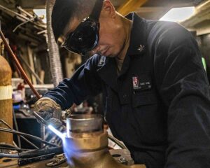
Groove Welding: What, Symbol, Diagram, Process, Machine, Strength and Several Facts

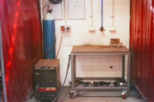
1024px Mig wielder 300x199 1

In this article, the topic ,”groove welding” with  groove welding connected facts such as, Symbol, Diagram, Process, Machine, Strength will be summarize.

The groove welding is used when the portion of the base metals are comes together to each other in a similar level. The groove welding is applied in the joints of the butt and it can be take a preparation before or after the process of welding in base metals. The most common groove welds known as, Butt joint.

What is groove welding?

The groove welding can be divided in two parts. One groove welding named as Single V groove and another groove welding named is Double V groove.

Groove welding can be defined as, groove welding actually a classification of welding process where the weld of the base metals is preserved in the groove received by the two feature of the plates of the butting or features of the tubes. Groove welding and Butt welding can be same.

Types of groove welding:

The shape for the preparation of the groove is the discerning creator for the classification of the weld of the groove.

Mainly groove welding can be classified in two parts,

  • Single V groove
  • Double V groove

The types of groove weld are based on the preparation of groove such and classified such as,

  • Single Bevel groove weld
  • Double Bevel groove weld
  • Single V groove weld
  • Double V groove weld
  • Single U groove weld
  • Double U groove weld
  • Single J groove weld
  • Double J groove weld
  • Flare V groove weld
  • Flare bevel groove weld

Groove welding symbols:

The parts which are consists of the weld of groove are Groove angle, Root face, Bevel angle, Root gap.

The steps which are describe the symbols for the Welds of the Grooves are listed below,

Determine the classification of the joint and preparation of the joined is required:-

The AWS A2.4:2007 is introduced by the American Welding Society they are published the symbol for the process of welding which contain different classifications of joints of groove which can be double or single. Single groove means joint by only one side and double groove means joint by both side. The symbols of the welding for the different types of joints of groove are listed below,

  • Bevel groove
  • V groove
  • Scarf
  • Square groove
  • U groove
  • J groove
  • Flare V groove
  • Flare bevel groove

Visualize the opening of the root:-

The opening of root will be indicating within the sign of the groove type. Root opening actually the amount of the detachment by the two pieces of the base metal. If detachment is not present showing that’s mean no space is present in by the parts. 0 is also admissible for the sign of the root opening.

Visualize the angle of the groove:-

The groove angle is expressed as degree. The angle of the groove can be present in the above section or the below section of the dimension of the root. The presences of groove angle depend upon the arrow.

Visualize the radii of the root and also the face dimension of the root:-

In the two ways, the radii of the root and also the face dimension of the root can be determined. The ways are listed below,

With the help of the drawing of cross section the dimension for the root opening is shown.

Need to note down the tail for the symbol of the welding process.

Visualize the thickness of the groove:-

The thickness of the preparation of the grooves is shown in the side of the left of groove weld symbol.

Visualize the size of the weld:-

In a groove weld, weld size is the effective throat. The weld size is included the penetration rate of the root of the groove and also the depth of the groove. The weld size will be display the left side of the symbol of the groove in parenthesis. If number is absent in the parenthesis then weld size not be lower than the depth of the groove.  

Visualize the contour finish:-

The contour finish for the fillet weld can be classified in three categorized, such as,

  • Flat contour finish
  • Concave contour finish
  • Convex contour finish

Visualize the finishing process:-

The symbol of the welding describes how much contour can be achieved. As a example, a flat contour by the grinding process the requirement is, AWS A2.4:2007 is introduced by the American Welding Society standard symbol for Brazing, Non-destructive investigation identified methods of finishing with 7th unspecified method,

  1. C – Chipping
  2. G – Grinding
  3. H – Hammering
  4. M – Machining
  5. P – Planishing
  6. R – Rolling
  7. U – Unspecified

Visualize the edge of the joint to be produce when the picture demands for a single bevel:-

In the case for the J groove, flare bevel and bevel symbol of welding inform us which side need to produce by having an arrow which is broken. When we observe the arrow which is already broken that’s mean the particular the side of the weld need to prepared. The most effective factor for the groove weld is, the size of the weld and the type of the weld.

Groove welding positions:

The process of groove welding can be serial following to the location of the workpiece or the joint of the welding in sections or plates being welded.

The American Welding Society according to the positions of the groove welding classified in four sections and they are listed below,

The symbols of the welding for groove are listed below,

  1. 1 representing to a position which is flat – either 1G
  2. 2 representing to a position which is horizontal – either 2G
  3. 3 representing to a position which is vertical – either 3G
  4. 4 representing to a position which is overhead – either 4G

1G or Flat position:-

The 1G or Flat position is work from the upper of the groove joint. The face of this type of weld is approximately in horizontal.

Another term for the 1G or Flat position is down hand.

In other word 1G or Flat position can be explained as, the deposition of the base metal is done from the above.

2G or Horizontal position:-

The position of the plate will be at vertical plane with the axis of the weld horizontal.

3G or Vertical position:-

The position of the plate will be at vertical plane with the axis of the weld vertical.

4G or Overhead position:-

The position of the plate will be at horizontal plane with the axis of the metal of the weld preserved from underneath.

When any type of conservation is done related to the position of the weld that time the main factor plays the role is face of the weld.

The number for the position of the weld is representing the type of the weld such as, F stands for Fillet, G stand for Groove.

Groove welding process:

In the process of the narrow groove welding is another name is narrow gap welding. The process of the narrow groove used to weld the sections which are comparatively thick.

To weld the any base metals with the help of V groove welding, the process of welding are used are listed below,

Gas tungsten arc welding:-

In the Gas Tungsten Arc Welding method (GTAW) an electrode is used which should be non consumable to produce high temperature near about 3800 degree centigrade and temperature have more melting point than the base metal to create the weld for the desired shape.

In the materials where Gas Tungsten Arc Welding method is applied are non – ferrous metals such as magnesium, aluminium, stainless steel.

Follow some basic process to run the Gas Tungsten Arc Welding method smoothly:-

Need to wear protective gear.

  1. The material use in the Gas Tungsten Arc Welding method should be clean.
  2. Keep the right angle of the torch.
  3. Minimum power should be use to run Gas Tungsten Arc Welding method.
  4. Filler rod should not be dissolve directly.
  5. Right Tungsten should be choosing.
  6. Working with the stainless steel.
groove welding
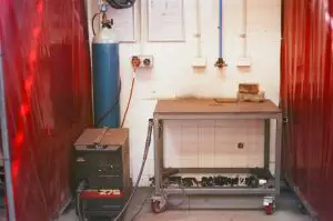
Image – Two red colored transparent welding curtains for shielding nearby persons from UV light exposure during welding; Image Credit – Wikipedia

Advantages:-

Advantages of Gas Tungsten Arc Welding method are listed below,

  1. Flux is not required.
  2. Clean welds can make with Gas Tungsten Arc Welding method.
  3. High quality weld can made with Gas Tungsten Arc Welding method.
  4. Allow all position of welding.
  5. Smoke is not produce.
  6. Sparks and slag also not produce.
  7. Work with verities of metals.
  8. Filler metal not essential.

Disadvantages:-

Disadvantages of Gas Tungsten Arc Welding method are listed below,

  1. Deposition rate is too low.
  2. High skilled welders are needed.
  3. Dissimilar metals cannot be work with the Gas Tungsten Arc Welding method.

Submerged Arc Welding:-

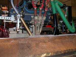
The welding process of submerged arc welding is used in various industrial fields such as, vessel construction and structural constriction. Submerged arc welding is automated process but also semi automated system is also available. The materials which are used in the submerged arc welding are low alloys steel, carbon steels, and nickel based alloys.
800px Submerged Arc Welding 1
Image – Submerged arc welding. The welding head moves from right to left. The flux powder is supplied by the hopper on the left hand side, then follow three filler wire torches and finally a vacuum cleaner;
Image Credit – Wikipedia

Advantages:-

Advantages of Submerged Arc Welding method are listed below,

  1. Less distortion.
  2. Thick material can be welded with the help of Submerged Arc Welding method.
  3. Minimal edge preparation.
  4. In the Submerged Arc welding method arc light emitted in very low portion.
  5. Very less emission of welding fume.
  6. Strong in nature.
  7. Both outdoor and indoor work can be done with the help of Submerged Arc Welding method.
  8. Deposition rate is too high.

Disadvantages:-

Disadvantages of Submerged Arc Welding method are listed below,

  1. Flux handing is difficult.
  2. Not portable.
  3. Submerged Arc Welding method may be limited to flat or horizontal-fillet welding positions.

Gas Metal Arc Welding:-

In the automotive sector and household purposes Gas Metal Arc Welding method is widely used. Gas Metal Arc Welding method Welding can be used in very thick metal sheet the metal sheet thickness can be vary upto 40 mm.

The materials which are used in the Gas Metal Arc Welding method Welding method are steels, non – ferrous materials.

In the Gas Metal Arc Welding method the equipments which are used are Welding power supply, Welding torch, Wire feed unit, Shielding gas supply and Welding electrode wire.

Advantages:-

Advantages of Gas Metal Arc Welding method are listed below,

  1. Skilled operator not needed to run the Gas Metal Arc Welding method.
  2. Allow all position of welding.
  3. By the help of Gas Metal Arc welding method alloys and metal both can be welded.
  4. The Gas Metal Arc Welding method is fully automated for this reason a huge amount of production can be made.
  5. Weld penetration is good.
  6. Strength of the Gas Metal Arc Welding method is superior with similar sizes of welds.
  7. Emission of welding fume is less.

Disadvantages:-

Disadvantages of Gas Metal Arc Welding method are listed below,

  1. Process is complicated.
  2. Initial cost is high.
  3. Maintenance cost is high.
  4. Pre cleaning is necessary for the base metals.
  5. Used base metal should be rust free.
  6. Deposition rate is not too high.
  7. Smaller construction cannot be done with the Gas Metal Arc Welding method.

Groove welding in flat position:

Groove welding in flat position is worked from the upper portion of the joint. The face of the groove welding in flat position is nearly stays at horizontal position.

The American Welding Society according to the flat positions of the groove welding classified in four sections and they are listed below,

  • 1G or Flat position
  • 2G or Horizontal position
  • 3G or Vertical position
  • 4G or Overhead position

The symbols of the welding for groove are listed below,

  • 1 representing to a position which is flat – either 1G
  • 2 representing to a position which is horizontal – either 2G
  • 3 representing to a position which is vertical – either 3G
  • 4 representing to a position which is overhead – either 4G

Groove angle in welding:

In a single-bevel groove weld, the included angle is same to the bevel angle but for a single-v groove weld, the included angle is not same to the bevel angle. If both plates were bevelled at the 30-degree angles, the included angle would be 60 degrees.

When to use groove welds in steel?

The groove welds in steel will be used when to come the parts of the base metal together in the same surface. The groove weld will be applied in a butt joint and may have a preparation or not before welding.

Groove welding use:

A groove weld will be used when the parts of the base metals come together in the same plane. Groove welds is applied in a butt joint and may have a preparation or not before welding. This is the reason there are several types of groove welding symbols.

Conclusion:-

The groove weld is, a lowland in the face of the workpiece or an opening between two joint members take measuring space to contain weld metal. When the characteristic of the plates of the butting are made groove in that particular case the groove welding and butt welding became same.
V Groove Welding: What, Symbol, Diagram, Process, Machine, Strength and Several Facts

800px Submerged Arc Welding 300x225 1

In this article, the topic, “v groove welding” with v groove welding involved facts like Symbol, Diagram, Process, Machine, Strength will be discuss.

V groove welding is a type of the groove welding. If the V groove welding is compare with another types of the welding then V groove welding is takes more time to perform, its time consuming process and very easily without skilled operator the V groove welding cannot be proceed.

The parts of the weld of groove are Groove angle, Root face, Bevel angle, Root gap.

What is v groove welding?

Groove weld can be classified in different types, among the all classification the groove classified in main two categorised such as, Single V groove and Double V groove.

The V – shaped groove of weld can be derive as, v shaped groove is the combination of,

  • The groove which is shapes as V in the area of the member.
  • Members of the butting carry the shape of the single bevel edge
  • Non butting and butting both members carrying surfaces of the planer prepared to create a groove.

The types of groove weld are based on the preparation of groove such and classified such as, Single Bevel groove weld, Double Bevel groove weld, Single V groove weld, Double V groove weld, Single U groove weld, Double V groove weld, Single J groove weld, Double J groove weld. The shape for the preparation of the groove is the discerning creator for the classification of the weld of the groove.

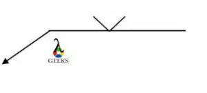
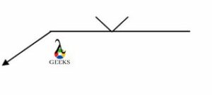
V groove welding symbol:

The welding symbol the V groove is given below,

v groove welding
Image – The welding symbol the V groove

Advantages symbols of the weld:-

Weld plays a very important role for where the flow of the work for any workpiece can be done in a smooth way. With the help of the symbols of the weld we easily can understand the size, shape and classification for this reason we don’t need to waste time to understand only about the weld. All information can be easily defined by the help of symbols of the welds.

Welding uses in V groove welding process:

In the process of the narrow groove welding is another name is narrow gap welding. The process of the narrow groove used to weld the sections which are comparatively thick.

To weld the any base metals with the help of V groove welding, the process of welding are used are listed below,

Gas Tungsten Arc Welding:-

Another name for the Tungsten Insert Gas Welding process is Gas Tungsten Arc Welding process. In the Tungsten Insert Gas Welding process electrode which is made tungsten is used and the electrode should be non – consumable type to create weld.

The base metals which can be work with Tungsten Insert Gas Welding process are, Aluminium and alloys of aluminium, carbon steel and alloys of carbon steel, stainless steel.

Submerged Arc Welding:-

Submerged Arc Welding (SAW) is a joining process that involves the formation of an electric arc between a continuously fed electrode and the workpiece to be welded. A blanket of powdered flux surrounds and covers the arc and, when molten, provides electrical conduction between the metal to be joined and the electrode.

800px Submerged Arc Welding
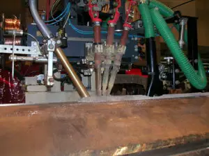
Image – Submerged arc welding. The welding head moves from right to left. The flux powder is supplied by the hopper on the left hand side, then follow three filler wire torch and finally a vacuum cleaner;
Image Credit – Wikipedia

Gas Metal Arc Welding:-

Metal insert gas welding process an example of arc welding method. In the Metal Insert Gas Welding process electrode which is used should be consumable type to create weld. The two base metals are joined with each other by the help of Metal insert gas welding process.

V groove welding angle:

The most suitable angle work with the geometry of V groove welding is 54 degree. In the 54 degree the properties of the mechanical is best for the tension strength.

Overhead v groove welding:

The most complicated position for working with the weld is overhead position. In the overhead v groove welding penetration rate is not too high.

Overhead v groove welding can be explained as; the process of the welding is accomplished together with two metal pieces above the welder. In the overhead v groove welding the experts are angled themselves and used equipment for reaching to the joints of the base metals.

Open v groove welding:

The symbols for the open v groove welding consists of,

  • Arrow line
  • Reference line
  • Weld procedure specifications

Double v groove welding:

Double v groove can be explain as, a classification of the weld of the groove in which one feature has a junction outskirts bevelled on too portions.

Frequent Asked Questions:-

Question: – Explain the advantages the joints of the welding.

Solution: – The welding joints are also known as permanent joints. In the welding joint the plates of the two metals are configuration or arrangement fitted tightly to each other.

The advantages the joints of the welding are listed below,

Leak proof joining:-

In some joining process main disadvantage is leakage is appearing post joining process, but in the process of the welding the base metals are joined without any leakage. Over the all joining process welding is leak proof.

Joining of the different shapes:-

Different types of shapes of the materials can be joined by the help of welding process. Almost every shape such as sheets, plates, bars can be joined by the process of welding.

Metals which are dissimilar are jointed:-

Without applying any filler metal the dissimilar metal can be joined with using the process of welding. Two or more than two dissimilar metal easily can be joined. Extra carefulness is required while dissimilar of two metals are joined with each other.

Strength of the joint is superior:-

The joining strength for the process of the welding is superior almost 100% strength we can get from the process of the welding.

High load capacity:-

The load capacity for the process of the welding is high. The components of the process of the welding are remain unchanged after completing the process.

Joining of plastics:-

The materials which are made with plastics in the welding process easily can be joined. In the other process of joining the material made with plastic can be damage, which is not requried at all.

Light welded assemblies:-

The joints made with weld are comparatively light weighted. The joints of the rivets required some additional equipment such as rivets, straps and many more.

Changing of the mechanical properties:-

By the help of the welding process various materials properties of the mechanical easily can be improved to reach the desired level. In the welding process electrode coating, protective gas, filler material are used to weld two pieces of the base metals.

Welding standards are define by two methods,

  1. International Organization for standardization
  2. ANSI / AWS A2.4 – 98

The ANSI / AWS A2.4 – 98 welding standard introduced by the American Welding Society.

Question: – Write some applications of the process of the welding.

Solution: – The process of welding applications are listed below,

  • Fabrication of vessels of the pressure
  • Spacecrafts
  • Aircrafts
  • Installation of the nuclear
  • Laying of railway tracks
  • Coaches of the railways
  • Laying of pipelines
  • Electrical industries
  • Defence industries

The applications for the process of the welding are also listed below,

  • Industries of the automobiles
  • Joining of the thin metals
  • Joining of the ferrous materials
  • Joining of the non ferrous materials
  • Fabrication of the sheet metals.

Question: – Write different types of welds used in the process of the welding.

Solution: – The different types of welds used in the process of the welding are listed below,

Question: – Discuss any three types of welds which are used in the process of the welding.

Solution: –

Three types of welds which are used in the process of the welding are discuss below,

Plug weld: –

By the help of the plug weld two base metals are locked with each other. The plug weld is used when two different types of metals which are contain different types of thickness need to joint with each other. In the piping system plug weld widely used to weld the inside of the tubes. After completing plug weld it takes shaped liked circular.

Groove weld:-

Groove weld can be explain as, an opening by the two members of the joints which are take steps area to with hold the base metal. After the use of fillet weld, the groove weld is used most.

Groove weld can be classified in some categorized such as,

  • Square Groove weld
  • Flare – V weld
  • Single – U groove weld
  • Single – V groove weld
  • Single – J groove weld
  • Flare – bevel weld
  • Single – bevel groove weld

Slot weld:-

By the help of the holes or elongated cavity slot weld is performed. The holes or gaps are filled with the weld of the base metal or it can be open by one side.

Square Groove Weld: What, Symbol, Diagram,Process, Machine, Strength and Several Facts

Capture 300x135 1

In this article, “Square groove weld” and square groove weld related several facts such as Symbol, Diagram, Process, Machine, and Strength will be discussed. Square groove weld is a type of Butt Welding Joint.

The limitation of the Square groove weld is the thickness of the joints. By the help of Square groove weld welders are creating joints in between one edge joint to another edges joints, although Square groove weld is also used to joints the corners, joints of the T and also joining the flat and curved pieces.

What is a square groove weld?

The work mechanism for the square groove weld is not very complicated and unskilled welder easily can work with the process of the square groove weld.

The square groove weld can be define as, it is the classification of the butt welding joint where two parallel and flat pieces are joint to each other. By the help of square groove weld a certain amount of strength can be provide to the joints. Joint thickness of the square groove weld is not so versatile.

Advantages:-

The advantages of the square groove weld are listed below,

  1. Inspection process with the square groove weld is easy. Easily defect can be identifying.
  2. Working mechanism square groove weld is not too much complicated.
  3. Economical to use.
  4. Distortion control is good for the square groove weld.
  5. Strength of the square groove weld is high.
  6. Penetration rate of square groove weld is too high almost 100%.
  7. Provide complete fusion.
  8. Stress produce by the square groove weld is very less.

Disadvantages:-

The disadvantages of the square groove weld are listed below,

  1. Geometrical application for the square groove weld is limited.
  2. With the weekly products like products of electronics cannot be work with the square groove weld.
  3. Not self aligning. When welders work with the square groove weld backer or fixturing is required.
  4. Impressionable to faying area condition.

Square groove weld symbol:

The groove of any square groove weld is made by the little amount of detachment of the margin or a tight fit. The weld symbol for the square groove weld is defining the total volume of detachment.

Square groove weld symbol is given below,

square groove weld
Image – Square Groove Weld

Square groove weld size:

The square groove weld is the term of the American National Standards Institute and butt weld is the term of the International Organization for Standardization.

The indication for the size of the square groove weld is the effective throat. The depth for the square groove easily can be defined by the size and also the penetration rate into the roots of the joints.

The term square groove weld and butt welds is the same classification of the weld.

Square groove weld strength:

The square groove weld is used to weld cheap and simple welding joints. In the sheet metal which thickness is less than the 5 mm in that case the square groove weld is used.

The strength of the square groove weld is depend upon some factors which are listed below,

Square groove weld example:

The examples of the square groove weld is listed below,

  • Metalworking magazine
  • Fabricating magazine
  • Construction of bridges

Frequent Asked Questions:-

Question: – Classify the types of the welding process.

Solution: – The process of welding we can classify in 9 categorised. The classification of the process of welding are listed below,

  • Tungsten Insert Gas Welding Process
  • Metal Insert Gas Welding Process
  • Thermic Welding Process
  • Forge Welding Process
  • Flux Cored Arc Welding Process
  • Resistance Welding Process
  • Stick Shield Metal Arc Welding Process
  • Submerged Welding Process
  • Oxyacetane Welding Process

Question: – Briefly describe any two types of the welding process.

Solution: – Two types of welding process is listed below,

Tungsten Insert Gas Welding Process:-

Another name for the Tungsten Insert Gas Welding process is Gas Tungsten Arc Welding process. In the Tungsten Insert Gas Welding process electrode which is made tungsten is used and the electrode should be non – consumable type to create weld.

The area of weld and electrode both are out of hazard from atmospheric contamination and oxidation with help of insert shielding gas. The shielding gas that could be use in the Tungsten Insert Gas Welding process is Helium and Argon.

The base metals which can be work with Tungsten Insert Gas Welding process are, Aluminium and alloys of aluminium, carbon steel and alloys of carbon steel, stainless steel.

800px US Navy 090715 N 5821P 002 Aviation Support Equipment Technician Airman Anthony Hammond performs tungsten inert gas welding during a training evolution
Image – Tungsten Insert Gas Welding process;
Image Credit – Wikipedia

Advantages:-

The advantages of the Tungsten Insert Gas Welding process are listed below,

  1. Tungsten Insert Gas welding process is clean.
  2. High quality weld can be making with Tungsten Insert Gas welding process.
  3. Smoke is not produce.
  4. A huge range of materials can be weld with the Tungsten Insert Gas welding process.
  5. Almost in every position Tungsten Insert Gas Welding process can be work.

Disadvantages:-

The disadvantages of the Tungsten Insert Gas Welding process are listed below,

  1. Deposition rate of the Tungsten Insert Gas Welding process is low.
  2. Skilled operators are needed to operate Tungsten Insert Gas Welding process.
  3. Speed of the welding is not too fast.
  4. Non automation.
  5. Initial cost of the Tungsten Insert Gas Welding process is high.

Metal Insert Gas Welding Process:-

Metal insert gas welding process an example of arc welding method. In the Metal Insert Gas Welding process electrode which is used should be consumable type to create weld. The two base metals are joined with each other by the help of Metal insert gas welding process. In the Metal insert gas Welding method the equipments which are used are listed below,

  • 1. Welding power supply
  • 2. Welding torch
  • 3. Wire feed unit
  • 4. Shielding gas supply
  • 5. Welding electrode wire
800px MIG cut away.svg
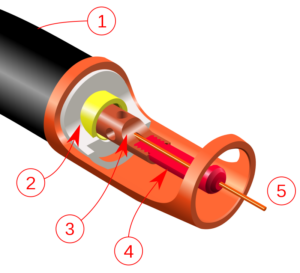
Image – GMAW torch nozzle cutaway image. (1) Torch handle, (2) Molded phenolic dielectric (shown in white) and threaded metal nut insert (yellow), (3) Shielding gas diffuser, (4) Contact tip, (5) Nozzle output face; Image Credit – Wikipedia

Advantages:-

The advantages of the Metal insert gas welding process are listed below,

  1. Deposition rate of the Metal insert gas welding process is too high.
  2. Flux is not needed to operate Metal insert gas welding process.
  3. Speed of welding is too high.
  4. The process of the Metal insert gas welding process can be automated without any problem.
  5. Ultra low hydrogen method.
  6. Dissimilar metals can be weld in the Metal insert gas welding process.
  7. Minor weld splatter.
  8. Thin metal sheet easily can be welded by Metal insert gas welding process.

Disadvantages:-

The disadvantages of the Metal insert gas welding process are listed below,

  1. Thick cannot be weld with the help of Metal insert gas welding process, only can work with 5 mm thick metal sheet.
  2. Metal preparation is required in Metal insert gas welding process.
  3. For the outside welding Metal insert gas welding process is not appropriate.

Question: – What is the advantage of using the square groove joint?

Solution: – With V-groove welds, the edges of both pieces are chamfered, either singly or doubly, to create the groove.

Each type of joint has its advantages and disadvantages, but the biggest advantage of the butt joint and square groove joint is its strength. It can withstand stress better than any other type of joint design.

Question: – Write down the difference between the groove weld and fillet weld.

Solution: – The difference between the groove weld and fillet weld is,

Fillet weld = A weld of nearly triangular cross section joining two surfaces approximately at right angles to each other in a lap joint, T-joint, or corner joint.

Groove Weld = A weld made in a groove between the workpieces.

800px Schweisen2
Image – Making a fillet weld with gas metal arc welding, Image Credit – Wikipedia

Question:- Classify the types of groove welds.

Solution: – The types of groove welds are listed below,

  • Flare-bevel weld
  • Flare-V weld
  • Single – bevel groove weld
  • Single-J groove weld
  • Single-U groove weld
  • Single-V groove weld
  • Square groove weld

Lathe Machine Uses: CNC, Wood, Center, Vertical Lathe Machine Uses

800px Watchmakers Lathe in use 300x200 1

In this article, the topic named “lathe machine uses” will be summarize. The lathe is machine tool which is conduct for starters for giving desired shape of a wood or metal.

Among the all lathe machine Engine lathe is most common lathe machine which is used in a wide range. By the help of lathe machine tool the main work which is done cutting the excess amount of material from the cutting tool and other work by the lathe machine is done is  shaping metal and wood.

Lathe machine uses to do operations:-

The operations done by the lathe machine is listed below by gripping the workpiece by chuck or centres,

  • Drilling operation
  • Facing operation
  • Turning operation
  • a. Taper turning operation
  • b. Straight turning operation
  • c. Shoulder turning operation
  • d. Rough turning operation
  • e. Eccentric turning operation
  • Grooving operation
  • Filing operation
  • Knurling operation
  • Chamfering operation
  • Polishing operation
  • Forming operation
  • Spring Winding operation
  • Spinning operation

The operations done by the lathe machine is listed below by gripping the angle plate or the faceplate or by the chuck of the machine tool,

  • Boring
  • Parting – off
  • Tapping
  • Drilling
  • Undercutting
  • Counter boring
  • Internal thread cutting
  • Reaming
  • Taper boring

The operations done by the lathe machine is listed below by behaving special link – ups,

  • Milling
  • Grinding
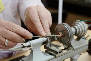
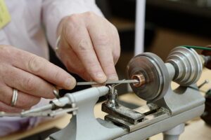
800px Watchmakers Lathe in use
Image – A watchmaker’s lathe in use to prepare a decorative watch component cut from copper;
Image Credit – Wikipedia

Advantages:-

The advantages of the lathe machine are listed below,

  1. In a short time medium type volume production to high type volume production can be made.
  2. Accuracy especially for the Computer Numerical Controlled lathe machine is very higher.

Disadvantages:-

The disadvantages of the lathe machine are listed below,

  • Initial cost for the lathe machine is high.
  • Maintenance cost is also high.
  • Tool wear appearing
  • Safety is needed
  • Skilled operator needed.
  • For the high cutting speed bad smell is appearing.

Computer Numerical Controlled lathe machine uses:

Operating system with the Computer Numerical Controlled lathe machine carried accurate instructions of designs. In the Computer Numerical Controlled lathe machine materials are placed and spin by the help of main spindle.

The uses for the Computer Numerical Controlled lathe machine are listed below,

  1. Cue sticks
  2. Baseball Bats
  3. Musical instruments
  4. Crankshafts
  5. Bowls
  6. Camshafts
  7. Gun Barrels
  8. Dining room table
  9. Dining room Chair legs

Cue sticks:-

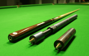
By the help of Computer Numerical Controlled lathe machine cue stick is produce. Cue stick is sports equipment which is used in carom, pool, and snooker. For striking a ball cue stick used.

lathe machine uses
Image – Snooker cue with two detachable extensions; Image Credit – Wikipedia

Baseball Bats:-

By the help of Computer Numerical Controlled lathe machine baseball bats are produce. Baseball bats can be metal or wooden smooth club. Baseball bats also a gaming item. In baseball game when pitcher thrown a ball for hitting the ball baseball bats are used.

Baseball bat 1
Image – Baseball Bats;
Image Credit – Wikimedia Commons

Musical instruments:-

For making musical instruments accuracy is very important for this reason only with the Computer Numerical Controlled lathe machine musical instruments are made of. From very earlier musical instruments are used for various objectives such as, rituals, as an entertainment concert of viewers, medicine and accompaniment of dances.

Crankshafts:-

For the internal combustion engine crankshaft is very important part. Crankshaft is made by the help of Computer Numerical Controlled lathe machine. The crankshaft is responsible for converting the motion of the linear to the motion of the rotational.

High fatigue strength should be carry by the crankshaft. The wear resistance of the crankshaft should be high.

Bowls:-

The bowls are made by the help of Computer Numerical Controlled lathe machine. Bowl is a container in round shaped foe consuming, serving and preparing any food item. In various types of culture bowls are used as a vessel where any type of food item is served and eaten.

The size of the bowls can be various types they can be small to large size. Small sized bowls are known as Tea bowl and which bowls are contained big sizes is generally known as Bowl.

Camshafts:-

For making the camshaft accuracy plays a very important role. In most of cases camshafts are made by the Computer Numerical Controlled lathe machine. The vehicles camshafts are in general made by metal. For making the camshaft in general chilled cast iron is used. A pointed cam is carried by the camshaft.

The main purpose of the camshaft is to transform the motion of rotational to the motion of reciprocal. The systems which are carried the camshaft are, ignition system which is controlled by mechanically, internal combustion engine and also in the electrically motor speed controller.

The other uses of the Computer Numerical Controlled lathe machine are,

  1. Gun Barrels
  2. Dining room table
  3. Dining room Chair legs

Parts:-

The parts which are carry by the Computer Numerical Control lathe machine is listed below,

  1. Computer Numerical Control panel
  2. Headstock
  3. Computer Numerical Control lathe bed
  4. Foot switch
  5. Tailstock
  6. Tool Turret
  7. Chuck
  8. Tailstock Quill

Advantages:-

The advantages of the Computer Numerical Control lathe machine is listed below,

  1. The machining process of the Computer Numerical Control lathe machine is more precise and accurate.
  2. To perform job in a workpiece takes very minimum time for this reason a medium volume production to high volume production easily can be make.
  3. Reliable
  4. Safe to operate.
  5. Complicated design can be made with the help of Computer Numerical Control lathe machine.
  6. Maintenance cost is low.
  7. Computer Numerical Control lathe machine can work for 24 hours.
  8. Versatile.
  9. Human errors are not possible because it is automated process.
  10. Huge numbers of labors are not needed to run the process.
  11. Uniform designs can be easily make.

Disadvantages:-

The disadvantages of the Computer Numerical Control lathe machine is listed below,

  1. Initial cost of the Computer Numerical Control lathe machine is too high.
  2. Skilled operator need to run the process.

Wood lathe machine uses:

With the help of the Wood lathe machine the material of wooden can be give desired shaped into a cylindrical profile.

The uses for the Wood lathe machine are listed below,

Wooden dining table made

  • Wooden dining table chair
  • Baseball bats
  • Bowls
  • Legs of the furniture
  • Lamp posts
  • Bed

Advantages:-

The advantages of the Wood lathe machine is listed below,

  1. The initial cost of the wood lathe machine is not too high.
  2. Maintenance cost is low.
  3. High skilled labor not needed to work with wood lathe machine.
  4. Simple in design.
  5. Light weight.
  6. Models can be carrying so easily by this wood lathe machine.
  7. Rotation control of the effective pulley is easy.
  8. Working mechanism is simple.

Disadvantages:-

The disadvantages of the Wood lathe machine is listed below,

  1. Rotation speed of the pulley is very low.
  2. Wood lathe machine cannot work with heavy materials.

Center lathe machine uses:

The Centre Lathe is used to produce cylindrical shapes from a range of materials including; steels and plastics. Many of the components that go together to make an engine work have been manufactured using lathes.

529px LatheDrivePlate carriers
Image – Dead center (the conical piece) mounted in the spindle of a lathe and being used to support a workpiece being driven by a carrier setup;
Image Credit – Wikipedia

Advantages:-

The advantages of the Center Lathe Machine are listed below,

  1. Pass rate advantage
  2. Mass production can be made easily with the Center Lathe Machine.
  3. Time Consuming.
  4. Accuracy of the Center Lathe Machine is very high.

Disadvantages:-

The disadvantages of the Center Lathe Machine are listed below,

  1. The initial cost is high.
  2. Skilled labor needed to operate.

Vertical lathe machine uses:

The Vertical Lathe Machine another name is Vertical Turing Lathe. The Vertical Lathe Machine is a machine tool which is raising the spindle of the machine tool in the plane which is situated vertically.

The complexity of the Vertical Lathe Machine is less compare to the horizontal lathe machine. The workpiece of the Vertical Lathe Machine can moving up, spin and also moving down to establish it in the row by the cutting head.The uses for the Vertical lathe machine are listed below,

  • Bore repairing
  • 4th Axis Machining
  • Press Plate Machining
  • Production Runs
  • Valve repairing
  • Three Dimensional Painting
  • Part Mapping
  • Casting Machining

Advantages:-

The advantages of the Vertical Lathe Machine is listed below,

  1. The construction of the vertical lathe machine is rigid.
  2. Stable performance.
  3. Efficiency of Vertical Lathe Machine is very high.
  4. Chips of the products can be removed easily.
  5. Time consuming.
  6. Medium volume production can be made with Vertical Lathe Machine.

Disadvantages:-

The disadvantages of the Vertical Lathe Machine is listed below,

  1. Heavy weight product cannot be work with the Vertical Lathe Machine.
  2. Skilled operator required to operate.

Read more about Hammer.

Mig Vs Arc Welding: When To Use What, Comparative Analysis On Different Factors

RK WL GMAW 1

This article discusses about the topic mig vs arc welding. Welding is a fabrication technique in which two or more metals are joined together with the help of heat and pressure.

Different sources of heat provide different amount of heat at the joint. Different amount of heat and pressure will result in welds of different properties. In this article we shall focus on two kinds of welding namely mig welding and arc welding. Let us start our discussion with the definition of welding.

What is welding?

Welding is a fabrication technique used to join two or more metals. This is done with the help of heat and pressure. An optimum amount of both these parameters are needed to provide the weld of desired properties.

If any one of the parameters is not properly regulated then the weld formation will not take place properly and the weld may break due to weakness. Different applications require different types of weld properties, so the sources of heat may be changes in order to make the welding process economical and energy saving.

What is mig welding ?

Mig welding stands for Metal inert gas welding. As the name suggests, this type of welding includes the participation of inert gas like Helium.

Helium protects the weld pool and the bare wire electrode. The welding takes place as a result of arc striking the surface of the work piece. The tip of the electrode is the place where arc takes place. The arc generates enough heat to create a weld pool in the surrounding area. A weld bead is formed which is allowed to cool at room temperature. This weld bead is the desired joint.

mig vs arc welding
Image: Mig welding

Image credits : WeldscientistRK WL GMAWCC BY-SA 4.0

What is Arc welding?

Arc welding as the name suggests uses an arc to fulfil the purpose of welding. The arc is generated by an AC or DC supply. A consumable or non consumable electrode can be used in this process.

There are four types of arc welding which are been discussed in the later section of this article. The heat generated from the arc is used to join the two metals. An arc is formed when there is high voltage passing through the electrode and the electrode is lifted by a very small distance from the work piece disconnecting the circuit. The arc flows through this short distance.

Mig vs arc welding strength

The strength of welds are different for different welding processes. The table below shows the difference between mig welding and arc welding strength.

Mig weldingArc welding
The welding is stronger on thinner materialsThe welding is weaker for thinner materials
The welding is weaker on thick materialsThe welding is stronger for thick materials
Table: MIg VS Arc welding strength

Gasless mig vs arc welding

The comparison between gasless mig vs arc welding is given in the table below

Gasless mig weldingArc welding
No gas is required for shieldingNo shielding is required
Better for both thin and thick sheets of metalsBetter for thick sheets for metals
The set up is expensiveThe set up is cheaper than gasless mig
Table: Gasless mig vs arc welding

Submerged arc welding vs mig welding

The comparison between submerged arc welding and metal inert gas welding is shown in the table below

Submerged Arc weldingMig welding
 Uses continuous feed wireUses continuous feed wire
Uses powdered flux for shieldingUses inert gases like Helium for shielding
Fully automaticSemi automatic
Used for only down handing weldingIt can be used in various positions
Used for very thick metalsUsed for thin plates.
Table: Submerged arc welding vs mig welding

Spray arc welding vs mig

Spray arc weldingMig welding
Molten metal droplets are transferred through the arcOnly electric spark is passed through the gap between electrode and the surface of workpiece
Used for thicker metals or butt jointsUsed for thin metal sheets
Table: Spray arc welding vs Mig welding

Shielded metal arc welding vs mig

Shielded metal arc weldingMig welding
Conventional arc welding process which uses a flux to shield the weld.A continuous wire is fed to the work piece. A spark between the tip of the wire and workpiece melts the wire and makes a weld pool
Manually operatedSemi automatic
The coating of the electrodes evaporates that acts as shielding gasInert gases like Helium is used for shielding
Table: Shielded Metal Arc Welding vs Mig Welding

Mig welding vs electric arc welding

Mig weldingElectric arc welding
Continuous wire is fed to the work pieceA stick electrode is used for welding process
Works on thinner materialsWorks on thicker materials
Uses inert gases for shielding Uses the evaporated electrode coating for shielding purposes.
Mig welding vs Electric arc welding

Is arc welding better than mig?

The answer to this question depends upon the type of application required. Both of these welding techniques are good for their respective application requirements.

If we want to weld thinner metals than mig welding is suitable as it gives a good finish for thin sheets of metals. When the metal is thick than a good weld will be formed when we use arc welding. Mig is not as effective on thicker metals as arc welding.

Sources of heat in welding

The following list shows the sources of heat in welding processes

  • Arc– Arc is formed when a high amount of voltage is passed through the electrode when it is in contact with the work piece. The electrode is lifted by a very small amount such that a small gap is created. Due to high voltage the electrons jump from the electrode to the surface of the work piece. This is called as an electric arc.
  • Plasma– Plasma is nothing but an electrically charged gas. This electrically charged gas particles produce enough heat on the surface of work piece that it can be used for welding
  • Torch– A torch is simply a flame throwing device with a nozzle through which flame comes out. The high temperature flame is directed towards the area where welding needs to be done.
  • Laser– The energy from lasers heat up the surface of work piece. The lasers produce a very high temperature at the surface of the work piece.
  • Electron beam– Electron beams can be directed to the work piece to provide heat energy at the surface. The electron beam is converged to a single point using deflecting apparatus.

Relative Humidity vs Absolute Humidity: Relationship, Graph, Formula, Chart

440px Australia 9am daily humidity average 300x207 1

In this article we will discuss about the different facts which gives a clarity of Relative Humidity Vs Absolute Humidity.

Both Relative Humidity and Absolute Humidity give indication about the water vapor present in the air but they are quite different from each other. Humidity measurement is done in different ways, all the methods have different applications. These methods are: Relative Humidity, Absolute Humidity and Specific Humidity.

 Humidity measurement is crucial whenever there is a need to prevent precipitation, corrosion, mould formation etc, mainly related to fields like food industries, medicine industries, wood works, cold storage, cooling tower in refineries etc.

Measurement of RH is the most common and used for a wide range of applications, calculation of RH for weather forecasting is a well-known fact.

For changing temperature measurement of absolute value of Humidity is preferred as it is independent of temperature. Absolute value is suitable for applications like Spray drying and blower.

440px Australia 9am daily humidity average
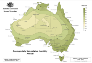
Average humidity around Australia year-round at 9 am, example of RH; Image Credit: Wikipedia 
  

Relative Humidity Vs Absolute Humidity

To measure the water vapor content in the air, most common and popular methods are Relative as well as Absolute method. Both indicates the moisture content but in two divers ways.

We can discuss their differences in a tabular form as below:

Absolute HumidityRelative Humidity
The absolute value of Humidity value gives us the total weight of water vapor per volume of air without considering the temperature. It can be calculated by dividing the total amount of water vapor mw by the given volume V of air.It can be calculated by dividing actual vapor pressure(E) in the air by the saturated value of vapor pressure Es multiplied by 100 at a fixed temperature.
pw = mw/V RH = (E/Es)x100
It is expressed in g/m3 RH value is expressed in percentage(%)
In the case of the Absolute method of humidity, measurement Temperature is not considered.RH is inversely proportional to Temperature.
Absolute Vs Relative

Relative humidity vs absolute humidity chart

RH value can be estimated from from a psychrometric or a Mollier diagram.

Mollier diagram is nothing but the European version of Anglo-American Psychrometric Chart, same parameters are used but look wise quite different from each other. Engineers and designers most widely used these diagrams as fundamental design implementation.

Psychrometric chart 2
Psychrometric Chart; Image Credit: Wikipedia

Air temperature(both dry and wet bulb temperature), amount of water vapor, enthalpy, RH values all are represented graphically in Psychrometric and Mollier charts.

If we know the dry bulb temperature and wet bulb temperature we can easily determine the RH value in the air using a psychrometric chart.

First of all find the specific dry bulb temperature on the horizontal axis of the chart and then find out the wet bulb depression value(i.e. Dry bulb temperature – Wet bulb temperature) on the vertical axis of the chart.

After that mark the point where these two lines from horizontal and vertical point intersect, this intersection point will give us the Relative value of humidity(RH) in percentage.

In the Psychrometric chart, we have Dry bulb temperature on the horizontal axis Humidity ratio(gm water/gm of dry air) on the vertical axis, and RH curves above.

For example, consider air with RH 60% at temperature 200Corresponding to the 200 we have to move until we reach 60% RH curve. Now move to the right side up to the end of the diagram to find the absolute humidity vertical line that will show the amount of water vapor in gm.

Absolute vs Relative Humidity Formula

Absolute value of Humidity gives us the total weight of water vapor per volume of air without considering the temperature, Relative method is an comparison between current value of absolute value of humidity and maximum possible value reached at a particular temperature.

The difference between Formulas used are as follows:

Absolute Humidity FormulaRelative Humidity Formula
Absolute pw  is the total amount of water vapor mw present in a given volume of air V regardless of temperature.RH can be calculated by dividing actual vapor pressure(E) in the air by the saturated value of vapor pressure Es , multiplied by 100 at a fixed temperature
pw = mw/VRH = (E/Es)x100
Absolute Vs Relative Formula

In case of Absolute type humidity measurement always remember that warmer air holds more moisture than colder air.

In case of Relative Humidity if temperature has increased keeping the Absolute Humidity same or keeping the moisture content same, the Relative Humidity will decrease.

By maintaining a constant Absolute value of Humidity, if we reduces the temperature in the atmosphere, a higher value of Relative value of Humidity will be observed.

Difference between Humidity and Absolute Humidity

Absolute type of humidity can be considered as a form or type of Humidity as it expresses the moisture content or water vapor content in the air in g/m3.

The differences between Humidity and Absolute Humidity Formula are as follows:

HumidityAbsolute Humidity
Humidity is water vapor content in the air. High humidity in the atmosphere makes us uncomfortable as we sweat more.Absolute(also known as water vapor density) humidity is the mass of water vapor per unit of dry air in a specific air volume.
Depending on the requirement of the applications we can adopt methods like Relative, Absolute and Specific Humidity to determine the humidity in surrounding environment.If the volume of air is not constant, the water vapor calculated by the Absolute method keeps changing along with the change in temperature and pressure. For this reason,  Absolute method is not applied in calculations related to chemical engineering.
Humidity Vs Absolute Humidity
440px Primary efflorescence decades later 001 1
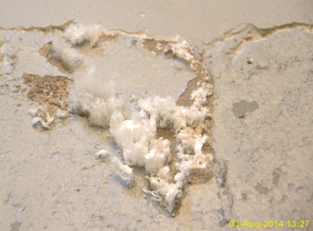
Effect of high humidity in building walls;Image Credit: Wikipedia

Difference between Absolute and Specific Humidity

Absolute and Specific Humidity are used to measure humidity.

To know the differences between Absolute and Specific Humidity we can go through the table below:

Specific HumidityAbsolute Humidity
Specific Humidity is the ratio of the mass of water vapor in the air to the total mass of air and water vapor.It is the actual mass of water vapor in unit volume of air.
Total air mass(including dry air) is consideredAir volume is considered
Specific humidity Unit is g/kg. Its Unit is g/m3.
Absolute and Specific Humidity

Humidity plays an important role in our daily life and devices called psychrometer or hygrometer are used to measure humidity in the air.

330px Haar Hygrometer 1
Hygrometer; Image Credit: Wikipedia
Relative Humidity
Amount of water in air at 100% RH across a range of temperature; Image Credit: Wikipedia

Cotter Pin Types: Uses, Size Chart

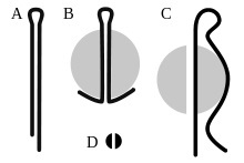
220px CotterPins

The cotter pin is used to fix different parts with special arrangements. Cotter pin types:

  • Split type cotter
  • Spring cotter pin
  • Tapered pin
  • Barrel type cotter pin
  • Dipped cotter
  • R type pin
  • Straight cotter
  • Split cotter pins

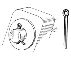
A cotter pin is a simple pin used to join two-part. It is passed through the holes between two-part to join or fix them. It is also known as a split pin in some countries.

cotter pin types
Split pin Credit Wikipedia

The cotter pins are available in various sizes and shapes. It is designed according to the applications and the load.

cotter pin types
Split pin Credit Wikipedia

Generally, these pins are manufactured from semi-circular wire with good hardness. The tapered pins are used to prevent the motion of the shaft in an axial direction.

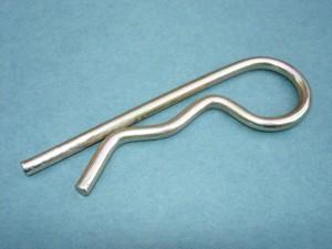
R Clip
R clip Credit Wikipedia

The tapered type of pin will face compression force in working conditions. This compressive force generates frictional force due to the tightness of the pin. Due to this friction force, the motion of the shaft is prevented.

Cotter pin size

The dimension of the cotter pin is decided based on the applications.

The length of the cotter pin is the distance from the eye portion to the short side of the pin. The diameter of the pin is to be measured more than the hole.

The eye of the pin is bigger than the diameter of the hole. The pin should fit properly through the hole based on the dimension.

Pin size
Pin sizes Credit Wikipedia

In actuality, the length of the pin is not fixed for every pin. It is manufactured based on the connections. The pin is measured from the connection of the pen and hole to the large end of the pin.

The size of the cotter pin starts from 1/32. There are two main dimensions of the cotter pin. One should know the length of the pin and the diameter of the pin.

The usage of the prongs is securing the connections properly. The hammer is used to increase the prong size. The prongs are used in some applications to better lock a pin in the hole. It does not allow the pin to escape from the hole.

Some precautions

  • The use of cotter pins is only once, Don’t reuse the pin.
  • The cotter pin should have a larger dimension than the hole.
  • The safety wire is the necessary part of the cotter pin. It is inserted properly through the pin.

Split pin vs. cotter pin

A cotter pin and split pin are locking devices used in various applications.

The material used to manufacture cotter pins and split pins is different. For the cotter pin, The material is mild steel (MS). The split pin is manufactured from grade steel.

The general use of a cotter pin is to lock the nut with the bolt. The cotter pin is kept in a hole provided in the bolt so that the nut cannot go out from the bolt. The cotter pin is bent to prevent the nut’s movement on the bolt.

Cotter pin uses

There are large applications of the cotter pin in various types of machinery.

A cotter pin prevents nut’s falling out due to vibrations. It is used in various types of machinery where the nut and bolt are present. It is a device that can easily fix locking problems.

The Replacement of the cotter pin is easy than another locking device. It can be easily removed from the machinery without interfering with other components.

There are many other locking nuts and devices available in equipment. A cotter pin only fails if the shear force is extreme. Its performance is far better than another locking device. For a while, any locking device fails due to continuous vibrations.

A cotter pin prevents the loosening of the nut. The cotter pin is only possible if the hole is provided in the bolt. There are some bolts available without a hole in them. If we want to fix a nut tightly in any equipment, we must have a bolt with the drilled hole.

The bolt is specially designed to use the cotter pin. There are two prongs in the construction of the cotter pin. The prongs are twisted in the opposite direction of each other to improve safety. It is recommended in all cases to twist the ends of the cotter pin. It is a low-cost fastener but saves huge machinery to get fail.

It prevents the nuts to get fall out in any vibration conditions.

What is cotter pin?

There is requirement of locking the nut with bolt in proper manner.

Vibration is a crucial issue in any machinery. It is critical to prevent all the bolts and nuts from vibrating conditions. A cotter pin is a device used to solve this problem in machinery.

It is famous in any place to lock the nut and bolt. It is a rode shape pin manufactured from mild steel. The construction of the pin is simple with the low cost of manufacturing. The eye is provided in a cotter pin larger than the hole diameter.

It is easy to replace the cotter pin in any machinery. The cost of the cotter pin is more nominal than other locking devices. Sometimes, a simple wire is used to lock nuts in emergency conditions.

How To Use A Lathe Machine: CNC, Wood, Center, Vertical Lathe Machine

In this article, the topic “How to use a lathe machine” will be discussed. The lathe machine can be describe as, a tool which spin around the workpiece above its axis to make many types of activities.

The manual lathe machine is works in some steps. The steps are listed below,

How to use a lathe machine steps are discussed:-

Preparation of the place and machine:-

  • At the beginning E – stop need to press.
  • The lathe machine need to clear and clean.
  • Workpiece should be secure.
  • The cutting tool should be chooses as per operation and then need to install.
  • In the next step the speed for the material and cutter need to determine in RPM (Revolution per minute).
  • After that, handwheel is a use for rotating the chuck of the lathe machine to verify for frictions.
  • The speed monitor turns into the lowest number.
  • At the final stages need to fix the lever into the condition of the forward.

Making the cut:-

  • Need to start the machine of the lathe.
  • Relief the E – stop.
  • Press the start button.
  • The speed range of the lever of the spindle is move from high to low or low to high.
  • In the next step the speed for the material and cutter need to determine in RPM (Revolution per minute).
  • After that, the cutting tool of the manual lathe machine move close to the starting point from where operation should be start.
  • The cutting tool mildly involved.
  • The first deduction pass is created.
  • At the final stage X axis and Z axis make in zero point.
  • The speed range of the lever of the spindle is move to the center thus the movement of the spindle can be stop.

Cleanup:-

  • E – Stop need to press.
  • Workpiece is removed.
  • The area of the lathe machine and also the lathe machine is clean by the help of vacuum or brush but not with the compressed air.
  • In the cutting of the tool chips are forms that’s should be clean with brush.
  • Any type of coolant is spills for clean up. Put away tolls, tooling and drill bits.
how to use a lathe machine
Image – A metalworking lathe from 1911, showing component parts:
a: bed
b: carriage (with cross-slide and tool post)
c: headstock

d: back gear (other gear train nearby drives lead screw)
e: cone pulley for a belt drive from an external power source
f: faceplate mounted on spindle
g: tailstock
h: leadscrew;

Image Credit – Wikipedia

How to use a cnc lathe machine?

In the Computer Numerical Control precise design can be making in a short time for this reason in modern generation CNC lathe machine is widely used in the various industrial fields.

The Computer Numerical Control lathe machine is works in some steps. The steps are listed below,

  • At first we should confirm that the lathe machine is totally powered down. Any type of risk should not be taken by turning the lathe machine neither accident can be appearing.
  • Safely charge the part.
  • Need to choose and charge the tools.
  • In the correct way calibrate the parts and the tools of the lathe machine.
  • Enter and run the machine.

Advantages:-

The advantages of the Computer Numerical Control lathe machine is listed below,

  1. The machining process of the Computer Numerical Control lathe machine is more precise and accurate.
  2. To perform job in a workpiece takes very minimum time for this reason a medium volume production to high volume production easily can be make.
  3. Reliable
  4. Safe to operate.
  5. Complicated design can be made with the help of Computer Numerical Control lathe machine.
  6. Maintenance cost is low.
  7. Computer Numerical Control lathe machine can work for 24 hours.
  8. Versatile.
  9. Human errors are not possible because it is automated process.
  10. Huge numbers of labors are not needed to run the process.
  11. Uniform designs can be make.

Disadvantages:-

The disadvantages of the Computer Numerical Control lathe machine is listed below,

  1. Initial cost of the Computer Numerical Control lathe machine is too high.
  2. Skilled operator need to run the process.

Applications:-

The applications of the Computer Numerical Control lathe machine is listed below,

  1. In the industrial fields of the metal removal.
  2. In the industrial fields of the material fabrication.
  3. In the industrial fields of the non conventional.

Parts:-

The parts of the Computer Numerical Control lathe machine is listed below,

  1. Computer Numerical Control panel
  2. Tool Turret
  3. Chuck
  4. Headstock
  5. Computer Numerical Control lathe bed
  6. Foot switch
  7. Tailstock
  8. Tailstock Quill

How to use a wood lathe machine?

With the help of the wood lathe a various types of operations can be done such as sand down, metal cutting, metal shaping, drilling the materials and many more.

The Wood lathe machine is works in some steps. The steps are listed below,

  • At the starting of the operation with the wood lathe machine we need to clarify the main parts such as, head, motor, tailstock, tool test and changeable speed options.
  • In the next step everything should be set up. Set up plays an important role to the operating the wood lathe machine. The blades of the cutter maximum are made with stainless steel thus it should be have enough sharpness and contain right amount of compositions.
  • Now, the tool bits or blades place onto the tool – rest at the angle of 900 and should be a certain distance between the person and the tool bits to avoid accident from the woods which are flying during the operation.
  • To make a perfect piece of cylindrical shape need to shave the stock evenly over the all places.
  • Any types of dangling and loose products always keep away from the wood lathe machine to avoid any type of accident.

Advantages:-

The advantages of the Wood lathe machine is listed below,

  1. The initial cost of the wood lathe machine is not too high.
  2. Maintenance cost is low.
  3. High skilled labor not needed to work with wood lathe machine.
  4. Simple in design.
  5. Light weight.
  6. Models can be carrying so easily by this wood lathe machine.
  7. Rotation control of the effective pulley is easy.
  8. Working mechanism is simple.

Disadvantages:-

The disadvantages of the Wood lathe machine is listed below,

  1. Rotation speed of the pulley is very low.
  2. Wood lathe machine cannot work with heavy materials.

How to use a mini lathe machine?

The knurling tool is made with high amount of 45 # carbon steel. Knurling tool specially made only for the mini lathe machine.

Like its more familiar, and much larger cousin, a mini lathe is used to work and shape metal and wood on a much more intricate scale and was designed and built to help you to create the smaller things that combine beauty and functionality in equal measure.

How to use a metal lathe machine?

In the metal lathe machine the workpiece is placed over the headstock Using jaw chuck. Jaw chuck works as a holder.

The metal lathe machine is used to cutting the excess amount of material from the workpiece and gives a desired shape. The metal lathe is works by moving the workpiece in the region of a cutting tool.

Advantages:-

The advantages of the Metal lathe machine is listed below,

  1. Rotation speed of the pulley is very high.
  2. Heavy metal easily can work with Metal lathe machine.
  3. Study.
  4. Metal lathe machine control by automated.

Disadvantages:-

The disadvantages of the Metal lathe machine is listed below,

  1. Working mechanism of the metal lathe machine is very complicated.
  2. To operate the metal lathe machine skilled operator needed.
  3. Maintenance cost is high.

Frequent Asked Questions:-

Question: – Write any three types of operation done by lathe machine.

Solution: – The operation done by the lathe machine is discuss bellow,

Facing:-

On the lathe machine tool facing is acts as a facing tool for cutting a flat area perpendicular to the job’s rotational axis. A facing tool is situated into a tool holder that is rest on the carriage of the machine tool of the lathe.

After that the tool will be feed perpendicularly to the area’s rotational axis as it rotates in the jaw of the chuck. The user has the option for hand feeding the machine tool of the lathe while facing or the power feed option can be use.

Centering:-

Centering is a process of gripping the job into chuck of the machine tool of the lathe, face place and drive plate on the center portion of the lathe machine. The process of the center is needed for the workpiece concentric to the center for the machining into the cylindrical shaped.

Grooving:-

Grooving is an operation by which diameter is reduced of a workpiece in a very narrow space. With the help of groove tool the operation grooving is done. Grooving tool is almost same to the parting tool. It is frequently done at the part of the end of a thread or neighbouring to a shoulder to parting a small margin.

Autogenous Welding: What, Types, Power Source, Exhaust, Machine and Examples

800px High power laser welding 300x200 1

In this article, “Autogenous welding “, with some different several facts like Types, Power Source, Exhaust, and Machine with interpretation are prate thoroughly. Autogenous welding filler material not needed.

Autogenous welding is a versatile welding process. In different types of methods of welding autogenous welding is applied. Some methods like oxyacetylene or gas tungsten arc welding can use autogenous or filler metal. Without applying filler metal autogenous welding is done to joined two or more metals.

What is autogenous welding?

The joint strength for the autogenous welding is not good at all. The joint strength is lower compare to the base plate’s strength. The part of the welded became weaker.

Autogenous is a method that link up two or more than two metals without any collection of filler metal. The most used joints in the autogenous welding are edge joint. The other types of joints can be made with the autogenous welding are corner joint and lap joint. Only tee joint cannot make with the autogenous welding.

Classifications of Autogenous welding process:

Autogenous welding is one kind of process of welding which is sustaining fusion welding method more than welding method of the specific fusion.

The Classifications of Autogenous welding process name with detailed facts are discuss below,

autogenous welding
Image – Orbital TIG Welding – Autogenous Welding – Micro-fit High Purity Tubing;
Image Credit – Wikimedia Commons

Gas tungsten arc welding:-

In the Gas Tungsten Arc Welding method (GTAW) an electrode is used which should be non consumable to produce high temperature near about 3800 degree centigrade and temperature have more melting point than the base metal to create the weld for the desired shape.

In the materials where Gas Tungsten Arc Welding method is applied are non – ferrous metals such as magnesium, aluminium, stainless steel.

Follow some basic process to run the Gas Tungsten Arc Welding method smoothly:-

  1. Need to wear protective gear.
  2. The material use in the Gas Tungsten Arc Welding method should be clean.
  3. Keep the right angle of the torch.
  4. Minimum power should be use to run Gas Tungsten Arc Welding method.
  5. Filler rod should not be dissolve directly.
  6. Right Tungsten should be choosing.
  7. Working with the stainless steel.

Advantages:-

  1. Flux is not required.
  2. Clean welds can make with Gas Tungsten Arc Welding method.
  3. High quality weld can made with Gas Tungsten Arc Welding method.
  4. Allow all position of welding.
  5. Smoke is not produce.
  6. Sparks and slag also not produce.
  7. Work with verities of metals.
  8. Filler metal not essential.

Disadvantages:-

  1. Deposition rate is too low.
  2. High skilled welders are needed.
  3. Dissimilar metals cannot be work with the Gas Tungsten Arc Welding method.

Laser beam welding:-

The welding method of Laser Beam Welding an evaporated laser beam is used to dissolve the base metal and create the weld for the desired shape.

Advantages:-

  1. Weld quality with Laser Beam Welding can be making in very preciously.
  2. Electrode is not needed.
  3. Laser Beam Welding is an automated method. With the help of robotic machinery a large amount of production easily can be made.
  4. Laser Beam Welding is a non contact method for this reason tool wear is not appear.
  5. In the Laser Beam Welding methods vacuum is not necessary for this reason in the air Laser Beam Welding easily can be done.
  6. In a very small space Laser Beam Welding preciously can be done.

Disadvantages:-

  1. Initial cost of Laser Beam Welding is too high.
  2. Maintenance cost of Laser Beam Welding also too high.
  3. Cracks are produce in Laser Beam Welding method for repetition of cooling.
  4. High skilled welders are needed.
  5. Only can work with 19 mm thick metals.

Electron beam welding:-

The welding method of Electron Beam Welding a strong force beam is used to dissolve the base metal and create the weld for the desired shape.

Advantages:-

  1. Operating cost is not too high.
  2. Welding speed for the Electron Beam Welding is too high.
  3. Dissimilar metals easily can be weld with Electron Beam Welding.
  4. Penetration rate to the width is high.
  5. Base metals with the temperature of melting point can be work with the Electron Beam Welding method.
  6. Rate of distortion is low.
  7. Reactive material such as titanium and beryllium can be work with Electron Beam Welding method.
  8. Inaccessible joints easily can be creating with Electron Beam Welding process.
  9. Electron Beam welding process can work with 0.025 mm to 100 mm thick metals sheets.

Disadvantages:-

  1. Equipment cost of the Electron Beam Welding is high.
  2. High skilled welders are needed.
  3. High vacuum in Electron Beam Welding process needed to run.
  4. High safety is required.
  5. Large amount of job cannot be performing well with the Electron Beam Welding.

Plasma arc welding:-

The welding method of Plasma Arc Welding ionized plasma arc is used to dissolve the base metal and create the weld for the desired shape.

Advantages:-

  1. Welding speed for the Plasma Arc Welding is high.
  2. High amount of energy is easily can get with Plasma Arc Welding.
  3. Penetration rate to the width is high.
  4. In low amperage Plasma Arc Welding can be work.
  5. Stable arc is creating.
  6. Low power consumption.

Disadvantages:-

  1. Noisy operation.
  2. High skilled welders are needed.
  3. Maintenance cost of Plasma Arc Welding also too high.
  4. More radiation Equipment cost is high.

Autogenous orbital welding:

Autogenous orbital gas tungsten arc welding (GTAW) is a controlled, precise welding method which is developed to decreases the chance of operator error and improve weld quality when joining tubes or other static workpieces with a non-consumable electrode.

Autogenous laser welding:

Autogenous laser welding is a fusion welding process.

Two metal pieces are joined together by the use of laser. It is focused to the cavity between the two metal pieces to be joined. Enough amount of energy is present and also expert hand is needed to operate autogenous laser welding process.

800px High power laser welding
Image – Autogenous laser welding;
Image Credit – Wikimedia Commons

Autogenous fusion welding:

Autogenous welding is a process of fusion welding. Autogenous welding does not need the filler metal application to form a weld. Since solid-state welding processes generally do not use filler materials, they may also be classified as autogenous.

Autogenous welding power source:

The power source of the autogenous welding are listed below,

Gas Metal Arc Welding:-

In the Gas Metal Arc Welding as a source electric arc is used that occurs fusion welding method.

Gas Tungsten Arc welding:-

Another name for the Gas Tungsten Arc welding is Tungsten Insert Gas Welding. The Gas Tungsten Arc welding is a type of arc welding where an electrode which is non consumable tungsten is used to make the weld.

In the materials where Gas Tungsten Arc Welding method is applied are non – ferrous metals such as magnesium, aluminium, stainless steel, alloys of copper.

Flux Cored Arc Welding:-

Another name for the Flux Cored Arc Welding is Dual Shield Welding. Flux Cored Arc Welding is semi automated arc welding process.

Shielded Metal Arc Welding:-

In the Shield Metal Arc Welding an electrode is used which is metallic consumable of an appropriate mixture for running arc by parent workpiece and itself. The dissolved metal of electrode full fills the gap of the weld and the workpiece joint with each other.

What kind of metal is exhaust in Autogenous welding?

The common classifications of steel used in exhaust process cover ferritic and austenitic stainless steel and also aluminium.

Autogenous welding examples:

Autogenous welding is most suitable for thin metal sheets.

The examples of autogeous welding and their details are prate below,

Gas tungsten arc welding:-

In the Gas Tungsten Arc Welding method (GTAW) an electrode is used which should be non consumable to produce high temperature near about 3800 degree centigrade and temperature have more melting point than the base metal to create the weld for the desired shape.

Application:-

  1. Gas Tungsten Arc Welding method can be work with aluminium and its alloys, alloys of stainless steel, alloys of magnesium, alloys of nickel base, alloys of copper base, alloys of low steels and carbon steel and many more.
  2. In hard facing Gas Tungsten Arc Welding is used.

Laser beam welding:-

The welding method of Laser Beam Welding an evaporated laser beam is used to dissolve the base metal and create the weld for the desired shape.

Application:-

  1. In industry of automotive Laser Beam Welding widely used.
  2. Making of jeweller Laser Beam Welding is used.
  3. To make high precision welds.
  4. Medical fields.

Electron beam welding:-

The welding method of Electron Beam Welding a strong force beam is used to dissolve the base metal and create the weld for the desired shape.

Application:-

  1. For making bridges, ship’s shell plates, electronic components, parts of the aircrafts Electron Beam Welding is used.
  2. Medical industries.
  3. Electron Beam Welding is use for joining titanium and alloys of the titanium.
  4. Aerospace industries.

Plasma arc welding:-

The welding method of Plasma Arc Welding ionized plasma arc is used to dissolve the base metal and create the weld for the desired shape.

Application:-

  1. Marine industries.
  2. Aerospace industries.
  3. Plasma Arc Welding is use for joining titanium and the alloys of the titanium and also stainless steel and the alloys of the stainless steel.
  4. Electronic industries.
  5. For repairing the tools, mould and die.
  6. Coating the blades of the turbines.

Examples of Non autogenous welding:

Some examples of Non autogenous welding are listed below,

  • Manual Metal Arc Welding
  • Flux Cored Arc Welding
  • Gas Metal Arc Welding

Brazing vs Welding: Comparative Analysis

800px SMAW area diagram.svg 300x209 1

“Brazing vs welding” topic will be prate in a brief manner in this article. The major difference between the welding and brazing is the source of heat.

In the welding and brazing process welder added filler metal into the joints of the metals. The difference between the Brazing and welding are discuss below,

Serial numberWeldingBrazing
1.Temperature used in the welding process is more than the melting point of a base metal. The temperature can maximum goes upto for welding process near about 38000 Temperature used in the brazing process is less than the melting point of a base metal. The temperature can maximum goes upto for brazing process near about 6000
2.Distortion rate for the welding process is moreDistortion rate for the brazing process is less.
3.Stress is appear in the base metals during the welding processStress is not appearing in the base metals during the brazing process.
4.Filler metals are not used during the welding processFiller metals are used during the brazing process.
5.The tensile strength is observe during the welding process and it range will be more than 200 MPaThe tensile strength is observe during the brazing process and it range will be between 100 – 150 MPa
6.Similar metal with made same composition and also the temperature of melting point of the base metals only can be joined togetherDissimilar metal with made dissimilar composition and also the different temperature of melting point of the base metals can be easily joined together.
7.For the large assembly welding is usedFor the small assembly brazing is used.
8.  By the help of welding stronger joints can be making.  By the help of brazing weaker joints comparative to the welding joints can be making.    
9.In the welding before doing the operation workpiece should be cleanIn the brazing before doing the operation workpiece should be clean but this not necessary.
10.In the welding process the properties for the metals are change after completing the process.In the brazing process the properties for the metals are not change after completing the process.
11.  Welding process can be define as, in which joining process both workpiece are dissolve together without or with application of filler metal using the upper temperature of melting point of the base metals.  Brazing process can be define as, in which joining process both workpiece are dissolve together with application of filler metal using the lower temperature of melting point of the base metals.  

Brazing process vs. Welding:

The process of brazing is safer compare to the welding process.

Welding process can be define as, in which joining process both workpiece are dissolve together without or with application of filler metal using the upper temperature of melting point of the base metals and Brazing process can be define as, in which joining process both workpiece are dissolve together with application of filler metal using the lower temperature of melting point of the base metals.

Brazing rod vs. Welding rod:

In the process of the brazing welding rods can be used.

In the welding process both workpiece are dissolve together without or with application of filler metal using upper temperature of melting point of the base metals in other way in the brazing process both workpiece are dissolve together with application of filler metal using the lower temperature of melting point of the base metals.

brazing vs welding
Image – Diagram of arc and weld area, in shielded metal arc welding. 1.Coating Flow;2.Rod;3.Shield Gas;4.Fusion;5.Base metal;6.Weld metal;7.Solidified Slag; Image Credit – Wikipedia

Brazing vs Welding:

Expert hands not needed in the brazing but in welding expert hands are needed.

The major difference between the process of welding and brazing is the source of heat. In the process of the brazing the source of the heat works as furnace, resistance, torch, dipped, induction and in the process of the welding the heat source works as electricity.

In the process of the brazing the temperature will be around 550 degree centigrade and the process of the brazing the temperature will be around 2800 degree centigrade.

What is the advantage of brazing over welding?

Both the welding and brazing are best solution. Sometimes brazing is appropriate for some applications and sometimes welding is appropriate for some applications.

The advantages of brazing over welding are discuss below,

Speedy operation:-

Brazing is a speedy operation compare to the welding process. In the brazing operation the processing temperature and power input is lower compare to the welding. The joints create by the brazing process have minimal residual stress and thermal distortion rate. The heat treatment process before doing the brazing operation is not needed. Dissimilar metal with made dissimilar composition and also the different temperature of melting point of the base metals can be easily joined together.

Less expensive:-

Brazing is an automated method although expert robotics is not needed to operate this process for this reason brazing became less expensive and money can be easily saves with this process.

Ideal production for mid volume to high volume:-

In the welding process productivity takes little more time but the brazing is automated process for this reason from medium volume production to high volume production easily can be make in a short time. The brazing is time consuming process.

Less complicated process:-

Temperature used in the welding process is more than the melting point of a base metal. The temperature can maximum goes upto for welding process near about 38000 for this reason the properties of the joints in base metals are changed and difficult to work with the melts of the base metal and also expert hands are needed all together welding became complicated process.

While, temperature used in the brazing process is less than the melting point of a base metal. The temperature can maximum goes upto for brazing process near about 6000 for this reason the properties of the joints in the base metals are not changed and not difficult to work with the melts of the base metal and also expert hands not are needed all together brazing became less complicated process.

Create cleaner joints:-

Irregular beads are made in the welding process that creates from the part. In the other way no beads or very small beads are made in the brazing process which is great for the welders.

Maintain tight tolerance:-

In the brazing process the base metals are not melt being joint for this reason the shape of the base metal not defected, while in the welding process the base metals are melt being joint for this reason the shape of the base metal are defected due to higher temperature than the melting temperature of the base metals.

800px Brazing aboard USS Ashland 48490045652
Image Credit – A US Navy maintenance technician torch brazes a steel pipe;
Image Credit – Wikipedia

Is brazing harder than welding?

In the welding process the properties of the base metals are changed.

Brazing harder than the welding or welding harder than the brazing is totally depending upon the joint configuration. The inner joints of the base metals are easy to weld and in the case of joining dissimilar metal brazing are easier than the welding.

Brazing vs. welding strength:

The method of brazing is not too much effective in the high temperature.

The joints strength for the base metals is strong in the process of the welding. Brazing process is work lower than the melting points for the base metals for this reason base metal does not dissolve. Rather, the source of the heat dissolve a filler metal and by the action of the capillary and compose it within the joints.

Brazing vs. welding cast iron:

Brazing is more suitable work with the cast iron.

Cast iron jobs are done in small repairing and in the case of brazing also suitable for small area repairing and risk of cracking is easily can be reduce for this while cast iron jobs are not suitable for welds.

Brazing vs. welding bike frame:

Bike frames are usually made with aluminium, carbon, steel even with cardboard.

With the both brazing and welding process frames of the bikes are made it’s totally depend on the materials and structure. With aluminium we easily can weld and with the steel frames of the bikes brazing can be done.

Brazing vs. welding steel:

Propane torch is used in the braze.

Brazing steel joint is stronger compare to the welding steel joint. A properly created brazed joint is more strong compare to the base metals being joined and the temperatures in that case remain low near about 600 degree centigrade.

Brazing vs. welding aluminium:

Brazing with aluminium is speedier.

In the joining of metals for aluminium brazing process is more quick compare to the Tungsten Insert Gas Welding process. The strength for the aluminium brazing and aluminium welding both are same.

Bronze brazing vs. welding:

For joining dissimilar metals bronze brazing is more effective.

In the welding process both workpiece are dissolve together without or with application of filler metal using upper temperature of melting point of the base metals in other way in the brazing process both workpiece are dissolve together with application of filler metal using the lower temperature of melting point of the base metals.

Fillet brazing vs. welding:

Brazing can joins permanently two metals with the help of torch.

Lugged joints and fillet brazed joints are done by heating the filler material (but not the base metal) to its melting point using a very hot flame, usually from oxy-acetylene or oxy-propane whereas welding is done by electrical current – basically tiny lightning bolts are used to melt the metals.