Thermal Diffusivity: 23 Interesting Facts To Know

Image5

Content

Thermal diffusivity definition

Thermal diffusivity is defined as the ratio of conducted heat to heat stored in material per unit volume.

Unit of Thermal diffusivity

The unit of thermal diffusivity is given as m2/s

Thermal diffusivity formula

The equation of thermal diffusivity is given by,

α = k/ρ

Where,

α is thermal diffusivity,

k is thermal conductivity  (w/mK)

? is the density of the material (kg / m3)

Cp is the specific heat (J/ kg k)

Thermal diffusivity of water

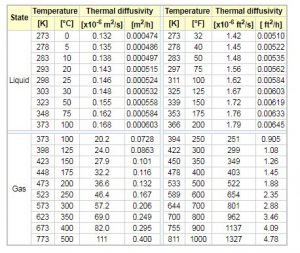
The thermal diffusivity of water changes with temperature and pressure. If we consider atmospheric pressure condition, then the thermal conductivity values with temperature are given as below table.
Thermal diffusivity
Thermal diffusivity of water and gas Credit Engineering toolbox

Thermal diffusivity of air

The thermal diffusivity of air with temperature change is shown in the above table. Generally , the thermal diffusivity of gas is more than liquid in practice. we will study is more in next topic.

Thermal diffusion

Thermal diffusion of substance is the relative motion of the molecules due to temperature gradient.

Thermal diffusivity of aluminium

Thermal diffusivity of aluminium material is given as 9.7 * 10-5 m2/s

Flash method Thermal diffusivity

The flash method is used to determine the thermal diffusivity of the material. The short duration radiant energy pulse is passed through the sample. The laser or light flash lamp source is used for radiant energy. The piece will absorb the emitted energy. The process is repeated for the sample. Due to this emitted radiation, there is a temperature increase of the material sample. The infrared temperature detector records this increase in temperature.

The duration of the measured signal is calculated. The thermal diffusivity will be found from the following equation.

α = 0.1388/l2(t2)

=

Where L is the sample thickness,

t/2 is the half time,

we can find thermal diffusivity, specific heat, and density using the flash method.

The schematic diagram of the flash method is shown in the figure below

Laser Flash Method scheme
Flash method of thermal diffusivity Credit Linseis

How to measure Thermal diffusivity

The thermal diffusivity can be measured using the flash method as discussed above. in this method, the short energy pulse is radiated one end, and temperature rise is calculated on the other end.

Thermal conductivity and thermal diffusivity

To differentiate between thermal conductivity and thermal diffusivity, consider two materials having the same thermal conductivity but with different thermal diffusivity. Both will permit the same rate of heat flow in the steady-state condition. At the start of the heat transfer process, the material with higher thermal diffusivity will reach a steady-state first compared to other material since it retains less heat energy. Heat energy penetrates fast through this material, but after getting a steady-state, the rate of heat flow will be the same. Also, remember that the material having less thermal diffusivity takes more time to reach the steady state.

Thermal diffusivity measurement techniques

There are mainly three types of thermal diffusivity measurement techniques.

  • Flash method
  • Thermal wave interferometry
  • Thermographic method

Thermal diffusivity of asphalt

The thermal diffusivity of the asphalt (Ah-70) is 0.123 mm2/s,

Asphalt (Ah-90) 0.128 mm2/s

Thermal diffusivity of rubber

The thermal diffusivity of the rubber material is in the range of 0.089-0.13 mm2/s

Thermal diffusivity values

Thermal diffusivity values for various materials are given in the table below. The values are changes with properties like temperature. These values are given for standard temperature and pressure.
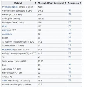
Capture
Thermal Diffusivity of various material Credit Wikipedia

Thermal diffusivity symbol

The symbol of thermal diffusivity is α

The highest Thermal diffusivity is of

The highest thermal diffusivity is of pure silver 165.63 mm2 / s

Thermal diffusivity of sand

Thermal diffusivity of dry sand varied from 0.6 * 10-7 to 7.0 * 10-7 m2/s.

Thermal diffusivity heat transfer

There are three modes of heat transfer conduction, convection and radiation. Heat conduction is dependent on main two properties. One is thermal conductivity and thermal diffusivity. Thermal conductivity is well-known property, but thermal diffusivity is not well known. It defines the rate of heat transfer through a given medium.

The rate of heat transfer is faster is the thermal diffusivity is higher. Thermal diffusivity is balancing between the medium of heat transfer and heat storage.

The Thermal diffusivities for gases are generally

The thermal diffusivities of gases substance are found more than liquid substance

Thermal diffusion coefficient

It is one of physical parameter which describes the dependency of mass diffusion flow of the mixture. In other words, the thermal diffusion coefficient is the ratio of a temperature gradient to the absolute temperature.

Thermal diffusion meaning

Thermal diffusion of substance is the relative motion of the molecules due to temperature gradient.

Glass Thermal diffusivity

The thermal diffusivity of glass is 0.34 * 10-6 m2/s  at normal atmospheric condition.

Stainless steel Thermal diffusivity

The thermal diffusivity of stainless steel at 100 °C is 4.55 *10-6 m2/s

Thermal diffusion ratio

The thermal diffusion ratio is the ratio of the thermal diffusion coefficient to the concentration coefficient.

FAQs

Thermal diffusivity of gas vs liquid

The thermal diffusivities of gases substance are found more than liquid substance

Which material has the highest Thermal diffusivity

The most increased thermal diffusivity is of pure silver 165.63 mm2 / s

Application of Thermal diffusivity

The conduction heat transfer in any apparatus requires the study of thermal diffusivity. The industries are using the analysis of thermal diffusivity to optimize the heat transfer rate.

If we take a particular example, then insulation is one example. In insulation, the thermal diffusivity of the material is minimum so that it can resist maximum heat flow.

We are using computers, laptops and other electronic gadgets. Do you know what the method to extract heat from devices is? Yes, it’s Heat sinks.

Heat sink requires higher thermal diffusivity to transfer faster heat from any gadgets.

An increase in heat transfer in any electronics degrades its performance. The higher thermal diffusivity material should be used to improve its performance in that case.

Thermal diffusivity of concrete

The thermal diffusivity of the concrete is 0.75 *10 -6 m2/s

What is the physical significance of thermal diffusivity?

Thermal diffusivity can be defined as the ratio of the thermal conductivity of the substance to the heat storage capacity of the substance.

The ratio defines the generated heat gets diffused out at a specific rate. The higher value of thermal diffusivity indicates that the time required for heat diffusion is less. The study of the equation of thermal diffusivity can be possible by the higher value of thermal conductivity or the lower value of heat capacity.

Image5

Thermal diffusivity is helpful for more intransient heat transfers. In steady-state heat transfer, the thermal conductivity is enough to study.

Why is the thermal diffusivity of gas greater than liquid even though the thermal conductivity of the liquid is greater than gases?

Thermal diffusivity means the ability of a material to transfer heat and store the heat at an unsteady state. A faster heat transfer can be possible if the thermal diffusivity is higher. The lower thermal diffusivity of material means the storage of heat in it.

Gas possesses low volumetric heat capacity because of low density. Due to low volumetric heat capacity, the value of thermal diffusivity is high.

Liquid possesses a high heat capacity compare to gas; hence thermal diffusivity is lower in the liquid.

What is the order of thermal diffusivity for solid, liquid, and gas?

The order of thermal diffusivity in solid, liquid and gas as shown below,

Gas > Liquid > Solid

What is the difference between momentum diffusion and thermal diffusion?

Momentum diffusion

It can be considered the kinematic viscosity of the fluid, i.e. the ability of the fluid to flow the momentum. Momentum diffusion is occurred by shear stress in a fluid. Shear stress causes a random and any direction movement of molecules.

Thermal diffusion

It can be defined as thermal conductivity divided by the multiplication of density and specific heat capacity (when the pressure is constant). It measures the heat transfer rate for a given material from the hot side to the cool side. It is predictive analogous to whether a given material is “cool to the touch.”

How is the Prandtl number related to kinematic viscosity and thermal diffusivity?

The Prandtl Number is dimensionless. It can be given as the ratio of momentum diffusivity (it is kinematic viscosity as explained above) to thermal diffusivity.

It can be formulated in equation as,

Pr = v/α

Pr = Prandtl number

V= momentum diffusivity ( m2/s )

α = Thermal diffusivity ( m2/ s )

MCQs

Thermal diffusivity is the _________

(a) Dimensionless parameter     (b) Function of heat       (c) Physical property of the material

(d) All of the above

Thermal diffusivity of a material is __________________?

(a) directly proportional with thermal conductivity (k)

(b) inversely proportional with the density of a material

(c) inversely proportional with specific heat

(d) all of the above

(e) none of the above

Find the wrong statement: Specific heat of a material ______________.

(a) Constant for a material           (b) Heat capacity per unit mass

(c) Extrinsic property                      (d) Has units as J/kg-K.

What is a unit of thermal diffusivity?

(a) m/h

(b) m²/h

(c) m/hk

(d) m²/hk

Thermal diffusivity of solid is less than liquid.

(a) True

(b) False

Thermal diffusivity is higher in…….

(a) Rubber

(b) Lead

(c) Iron

(d) Concrete

Thermal diffusivity is lower in……

(a) Rubber

(b) Lead

(c) Aluminum

(d) Iron

Find more articles to related topic click here

Principal stress: 23 Facts You Should Know

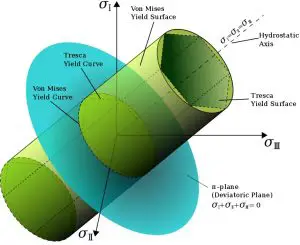
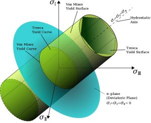
Von mises 300x245 1

Principal Stress Definition:

Principal Stress is the maximum and minimum stresses derived from normal stress at an angle on a plane where shear stress is zero.

How to calculate principal stress ?

Principal stress equation | Principal stress formula:
Maximum and Minimum principal stress equations:

\\sigma 1=\\frac{\\sigma x+\\sigma y}{2}+\\sqrt{(\\frac{\\sigma x-\\sigma y}{2})^{2}+\\tau xy^{2}}

\\sigma 1=\\frac{\\sigma x+\\sigma y}{2}-\\sqrt{(\\frac{\\sigma x-\\sigma y}{2})^{2}+\\tau xy^{2}}

Principal stress derivation | Determine the principal planes and the principal stresses

Normal stresses:

\\sigma x'=\\frac{\\sigma x+\\sigma y}{2}+\\frac{(\\sigma x-\\sigma y)(cos2\\Theta )}{2}+\\sigma xysin2\\Theta

\\sigma y'=\\frac{\\sigma x+\\sigma y}{2}-\\frac{(\\sigma x-\\sigma y)(sin2\\Theta )}{2}+\\sigma xycos2\\Theta

-\\frac{(\\sigma x-\\sigma y)(cos2\\Theta )}{2}+\\sigma xysin2\\Theta

Differentiate,

\\frac{dx'}{d\\Theta }=0

tan2\\Theta =\\frac{\\sigma xy}{\\frac{(\\sigma x-\\sigma y)}{2}}

tan2\\Theta_{p} =\\frac{\\sigma xy}{\\frac{(\\sigma x-\\sigma y)}{2}}

“p” represents the principal plane.

There are two principal stresses,
one at angle 2\\Theta
and other at 2\\Theta+180
Maximum and Minimum principal stresses:

R=\\sqrt{(\\frac{\\sigma x-\\sigma y}{2})^{2}+\\tau xy^{2}}

cos2\\Theta =\\frac{\\left ( \\sigma x-\\sigma y \\right )}{2R}

sin2\\Theta =\\frac{\\sigma xy}{R}

substitute in equation 1:

\\sigma x'=\\frac{\\left ( \\sigma x+\\sigma y \\right )}{2}+\\frac{1}{R}[\\left ( \\frac{\\sigma x-\\sigma y}{2} \\right )^{2}+\\sigma xy^{2}]

substitute value of R

Maximum and minimum normal stresses are the principal stresses:

\\sigma max=\\frac{\\sigma x+\\sigma y}{2}+\\sqrt{(\\frac{\\sigma x-\\sigma y}{2})^{2}+\\tau xy^{2}}

\\sigma min=\\frac{\\sigma x+\\sigma y}{2}-\\sqrt{(\\frac{\\sigma x-\\sigma y}{2})^{2}+\\tau xy^{2}}

The state of Stress:

The principal stress is the reference co-ordinate axes to the representation of the stress matrix and this stress components are the significance of the state of stress could be represented as,

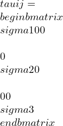
Stress tensor:

\\tau ij=\\begin{bmatrix}\\sigma 1 & 0 & 0 \\\\0 & \\sigma 2 & 0 \\\\0 &0 &\\sigma 3\\end{bmatrix}

Principal stresses from stress tensor and stress invariants |principal stress invariants

There are three principal planes at any stressed body, with normal vectors n, called principal directions where the stress vector is in the same direction as normal vector n with no shear stresses and these components depend on the alignment of the co-ordinate system.


A Stress vector parallel to the normal unit vector n is specified as,

\\tau ^{\\left ( n \\right )}=\\lambda n=\\sigma _{n}n

Where,
\\lambda represents constant of proportionality.

The principal stress vectors represented as,

\\sigma ij nj=\\lambda ni

\\sigma ij nj-\\lambda nij=0

The magnitude of three principal stresses gives three linear equations.
The determinant of the coefficient matrix is equal to zero and represented as,

\\begin{vmatrix}\\sigma ij-\\lambda \\delta ij\\end{vmatrix}=\\begin{bmatrix}\\sigma 11-\\lambda &\\sigma 12 &\\sigma 13 \\\\\\sigma 21 & \\sigma 22-\\lambda &\\sigma 23 \\\\\\sigma 31 & \\sigma 32 & \\sigma 33-\\lambda\\end{bmatrix}

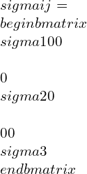
Principal stresses are the form of normal stresses, and the stress vector in the coordinate system is represented in the matrix form as follows:

\\sigma ij=\\begin{bmatrix}\\sigma 1 & 0 & 0\\\\0 & \\sigma 2 & 0\\\\0 &0 &\\sigma 3\\end{bmatrix}

I1, I2, I3 are the stress invariants of the principal stresses,
The stress invariants are dependent on the principal stresses and are calculated as follows,

I1=\\sigma 1+\\sigma 2+\\sigma 3

I2=\\sigma 1\\sigma 2+\\sigma 2\\sigma 3+\\sigma 3\\sigma 1

I3=\\sigma 1.\\sigma 2.\\sigma 3

The principal stresses equation for stress invariants:

\\sigma 1=\\frac{\\sigma x+\\sigma y}{2}+\\sqrt{(\\frac{\\sigma x-\\sigma y}{2})^{2}+\\tau xy^{2}}

\\sigma 1=\\frac{\\sigma x+\\sigma y}{2}-\\sqrt{(\\frac{\\sigma x-\\sigma y}{2})^{2}+\\tau xy^{2}}

Principal stress trajectories | Principal directions of stress

Stress trajectories show the principal stress directions and their varying magnitude of the principal stresses.

Von mises stress vs principal stress

Von mises principal stress equation

Von Mises is the theoretical measure of the stress yield failure criterion in ductile materials.
The positive or negative sign depends on the principal stresses.
Principal stresses Boundary conditions:

\\sigma 12=\\sigma 23=\\sigma 31=0

Theories of failure give the yield stresses of the components subjected to multiaxial loading. Further, when it is compared with the yield point of the components shows the margin of the safety of the component.

Maximum principal stress is considered for brittle elements such as casting components (i.e., clutch housing, gearbox, etc.)
Von-mises stress theory is based on shear strain energy theory is suggested for ductile materials like aluminum, steel components.

Why von mises stress is recommended for ductile and Principal Stress for brittle materials?


Failure of brittle materials used to uni-axial test is along a plane vertical to the axis of loading. So, the failure is because of normal stress generally. Out of all theories of failure, principal stress theory is based on normal Stress. Hence for brittle materials, principal stress theory is recommended,

Ductile materials fail at 45 degrees inclined at the plane of loading. So, the failure is due to shear stress. Out of all theories of failure shear strain energy or von-mises theory and maximum shear stress theory is based on shear stress. By comparison, von mises gives better results. Hence for ductile materials, von mises theory is recommended.

Different types of stress

Absolute principal Stress | Effective principal Stress:

The principal stresses are based on maximum Stress and minimum Stress. So, the range of the Stress is between the maximum and minimum Stress, (stress range is limited and less) and might lead to higher fatigue life. So, it is important to find out the effective principal Stress that gives the maximum value out of the two over the given period of time.

What is Maximum Normal Stress theory?

This states that brittle failure occurs when the maximum principal Stress exceeds the compression or the tensile strength of the material. Suppose that a factor of safety n is considered in the design. The safe design conditions require that.

Maximum principal stress equation

-\\frac{Suc}{n}<{\\sigma 1,\\sigma 2,\\sigma 3}<\\frac{Sut}{n}

Where σ1, σ2, σ3 are three principal stresses, maximum, minimum, and intermediate, in the three directions, Sut and Suc are the ultimate tensile strength and the ultimate compressive strength, respectively.

To avoid brittle failure, the principal stresses at any point in a structure should lie within the square failure envelope based on the maximum normal stress theory.


Maximum principal stress theory |Maximum principal stress definition

consider two-dimensional stress state and the corresponding principal stresses such as σ1 >σ2 >σ3
Where σ3=0, σ2 may be compressive or tensile depending on the loading conditions where σ2 may be less or greater than σ3.

2 1

According to maximum principal stress theory, failure will occur when
σ1 or σ2 =σy or σt
The conditions are represented graphically with coordinates σ1,σ2. If the state of Stress with coordinates (σ1,σ2 ) falls outside of the rectangular region, failure will occur as per the maximum principal stress theory.

Mohr’s circle principal stresses

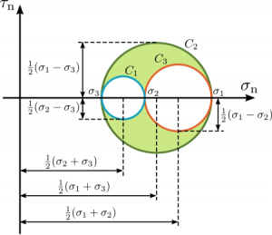
Explain the Mohr’s circles for the three-dimensional state of stress:

  • Consider a plane with a reference point as P. Sigma is represented as normal Stress and tau by the shearing stress on the same plane.
  • Take another plane with reference point Q representing sigma and tau as normal stress and shear stress, respectively. Different planes are passing through point p, different values of principal and shear stress.
  • For each plane n, a point Q with coordinates as shear stress and principal Stress can be located.
  • Determine the normal and shear stresses for point Q in all possible directions of n.
  • Obtain three principal stresses as maximum principal Stress, minimum principal Stress, and intermediate principal Stress and represent them in ascending order of the values of the stresses.
  • Draw three circles with diameters as the difference between the principal stresses.
moh's circle:principal stress
Image credit:SanpazMohr Circle, marked as public domain, more details on Wikimedia Commons
  • The shaded area region is the Mohr’s circle plane region.
  • The circles represent the Mohr’s circles.
  • (σ1-σ3) and the associated normal stress is (σ1+σ3)
  • There are three normal stresses, so are three shear stresses.
  • The principal shear planes are the planes where shear stresses act and principal normal stress acts at a plane where shear stress is ‘0’ and shear stress act at a plane where normal principal stress is zero. The principal shear stress act at 45° to the normal planes.


The shear stresses are denoted by \\tau 1,\\tau 2,\\tau 3
And the principal stresses are denoted by \\sigma 1,\\sigma 2,\\sigma 3

Third principal stress

3rd principal Stress is relative to the maximum compressive stress due to the loading conditions.

3D principal stress examples:

For three-dimensional case, all three planes have zero shear stresses, and these planes are mutually perpendicular, and normal stresses have maximum and minimum stress values and these are the normal stresses that represent the principal maximal and minimal stress.

These principal stresses are denoted by,
σ1,σ2, σ3.
Example:
3D Stress in hub-a a steel shaft is force-fitted into the hub.
3D Stress in machine component.

Principal deviatoric stress:

Principal deviatoric stresses are obtained by subtracting mean Stress from each principal Stress.

Intermediate principal Stress:

The principal Stress, which is neither maximum nor minimum, is called intermediate Stress.

Principal stress angle | Orientation of principal stress: θP

Orientation of the principal Stress is computed by equating shear stress to zero in x-y direction at the principle plane rotated through an angle theta. Solve θ to get θP, the principal stress angle.

Important Frequently Asked Questions (FAQs):


Maximum principal stress theory is applicable for which material?

Answer: Brittle materials.

What are the 3 principal stresses? | What is maximum and minimum principal stress ?

Maximum principal Stress | Major principal stress: Most tensile (σ1)
Minimum principal Stress | Minor Principal Stress: Most compressive (σ3)
Intermediate principal Stress (σ2)

Principal Stress vs normal Stress:

Normal Stress is the force applied to the body per unit area. Principal Stress is the stress applied to the body having zero shear stress principal Stress is in the form of normal Stress giving maximum and minimum stresses on the principal plane.

Principal Stress vs Bending Stress:

Bending Stress is the Stress that occurs in the body due to the application of a large amount of load that causes the object to bend.

Principal Stress vs axial Stress:

Axial Stress and principal stress are the parts of normal stress.

What is the significance of principal Stress?

Principal Stress shows the maximum and minimum normal stress. Maximum normal Stress shows the component’s ability to sustain the maximum amount of force.

What are the principal stresses in a shaft with torque applied ?

The shear stress due to torque has maximum magnitude at the outer fiber. The bending stress is due to horizontal loads (horizontal gear forces, belt, or chain forces) that induce bending stresses which are maximum at the outer fibers.

Why shear stress is zero on principal plane ?

The normal Stress is maximum or minimum, and shear stress is zero.

tan2\\Theta _{\\tau-max}=-(\\frac{\\sigma x-\\sigma y}{2\\tau xy})

\\tau max=\\sqrt{(\\frac{\\sigma x-\\sigma y}{2})^{2}+\\tau xy^{2}}

when shear stress=0,

\\tau max=\\frac{\\begin{vmatrix}\\sigma x-\\sigma y\\end{vmatrix}}{2}

Important Principal stress problems:

1) A rectangular stress vector having shear stress in XY direction of 60Mpa and normal tensile Stresses of 40Mpa.How to find principal stresses ?

Solution:
Given: \\sigma x=\\sigma y=40Mpa , \\tau=60Mpa
Principal stresses are calculated as,

\\sigma 1=\\frac{\\sigma x+\\sigma y}{2}+\\sqrt{(\\frac{\\sigma x-\\sigma y}{2})^{2}+\\tau xy^{2}}

σ1=100Mpa

\\sigma 1=\\frac{\\sigma x+\\sigma y}{2}-\\sqrt{(\\frac{\\sigma x-\\sigma y}{2})^{2}+\\tau xy^{2}}

σ2=-20Mpa

2)What are the coordinates of the center of Mohr’s circle for an element subjected to two mutually perpendicular stresses, one tensile of magnitude 80MPa and other compressive of magnitude 50MPa?

σx = 80 MPa,
σy = -50 MPa
Co-ordinates of center of Mohr’s circle =[ ½( σx + σy),0]
= [(30/2),0]
= (15,0)

3)A body was subjected to two mutually perpendicular stresses of -4MPa and 20MPa, respectively. Calculate the shear stress on the plane of the shear.

σx+σy /2= -4+20/2 = 8Mpa
Radius= σ1-σ2/2 = 20-(-4)/2 = 12
where σx,σy are principal stresses
at pure shear stress,σn=0
shear stress= squareroot12^2-8^2= 8.94Mpa.

4) Application of principal stress | Find the principal stresses for the following cases.

i)σx=30 Mpa, σy=0, \\tau=15Mpa.

solution:

\\sigma 1=\\frac{\\sigma x+\\sigma y}{2}+\\sqrt{(\\frac{\\sigma x-\\sigma y}{2})^{2}+\\tau xy^{2}}

σ1=36.21Mpa

\\sigma 1=\\frac{\\sigma x+\\sigma y}{2}-\\sqrt{(\\frac{\\sigma x-\\sigma y}{2})^{2}+\\tau xy^{2}}

σ2=-6.21Mpa
ii)σx=0,σy=80MMpa, \\tau=60Mpa.

\\sigma 1=\\frac{\\sigma x+\\sigma y}{2}+\\sqrt{(\\frac{\\sigma x-\\sigma y}{2})^{2}+\\tau xy^{2}}

σ1=97Mpa

\\sigma 1=\\frac{\\sigma x+\\sigma y}{2}-\\sqrt{(\\frac{\\sigma x-\\sigma y}{2})^{2}+\\tau xy^{2}}

σ2=12.92Mpa


iii)\\tau=10Mpa, σx=50Mpa,σy=50Mpa.

\\sigma 1=\\frac{\\sigma x+\\sigma y}{2}+\\sqrt{(\\frac{\\sigma x-\\sigma y}{2})^{2}+\\tau xy^{2}}

σ1=60Mpa

\\sigma 1=\\frac{\\sigma x+\\sigma y}{2}-\\sqrt{(\\frac{\\sigma x-\\sigma y}{2})^{2}+\\tau xy^{2}}

σ2=40Mpa

5) The maximum principal Stress is given 100 Mpa, and the Minimum principal Stress is 50 MPa. Calculate the maximum shear stress and the orientation of the principal plane using Mohr’s circle.

Given:
Maximum principal stress=100Mpa(compressive)
Minimum principal stress=50 Mpa(compressive)
Solution:
Maximum shear stress is the radius of the Mohr’s circle, then we can write as follows.

R=\\sqrt{(\\frac{\\sigma x-\\sigma y}{2})^{2}+\\tau xy^{2}}

\\tau max=25Mpa

2θ = 90, from the maximum principal stress direction.
So, the orientation at that point is θ = 45 from the maximum principal stress direction.

For more Mechanical Engineering related article click here

Shear modulus |Modulus of rigidity | It’s important facts and 10+ FAQ’s

What is Shear modulus ?

Modulus of Rigidity definition

Shear modulus is the ratio of the shear stress to the shear strain.

Shear modulus is defined as the measure of the elastic shear stiffness of the material and it is also acknowledged as ‘modulus of rigidity’. So, this parameter answers the question of how rigid a body is?
Shear modulus is the material response to a deformation of body because of the shearing stress and this work as ‘the resistant of the material to shearing deformation’.

shear modulus
Image credit:C.linggShear scherung, marked as public domain, more details on Wikimedia Commons

In the above figure, Side lengths of this element will not change, though the element experiences a distortion and shape of element is changing from the rectangle to a parallelogram.

Why do we calculate the modulus of rigidity of the material ?
Shear modulus equation | Modulus of Rigidity equation

Shear modulus is the ratio of the shear stress to the shear strain, which is measures the amount of distortion, is the angle (lower case Greek gamma), always ex-pressed in radians and shear stress measured in force acting on an area.
Shear modulus represented as,
G=\\frac{\\tau xy }{\\gamma xy}
Where,
G= shear modulus
τ=shear stress = F/A
ϒ = shear strain=\\frac{\\Delta x}{l}

modulus of rigidity symbol

G or S or μ

What is the SI unit of rigidity modulus ?

Shear modulus units | Unit of modulus of rigidity

Pascal or usually denoted by Giga-pascal. Shear modulus is always positive.

What is the dimensional formula of modulus of rigidity ?

Shear modulus dimensions:

[M^{1}L^{-1}T^{-2}]

Shear modulus of materials:

Shear modulus of steel | Modulus of rigidity of steel

Structural steel:79.3Gpa
Modulus of rigidity of stainless steel:77.2Gpa
Modulus of rigidity of carbon steel: 77Gpa
Nickel steel: 76Gpa

Modulus of rigidity of mild steel: 77 Gpa

What is the Rigidity modulus of copper in N/m2 ?
Modulus of rigidity of copper wire:45Gpa
Shear modulus of Aluminum alloy: 27Gpa
A992 Steel: 200Gpa
Shear modulus of concrete | Modulus of rigidity of concrete: 21Gpa
Silicon shear modulus: 60Gpa
Poly ether ether ketone (PEEK):1.425Gpa
Fiberglass shear modulus: 30Gpa
Polypropylene shear modulus: 400Mpa
Polycarbonate shear modulus: 5.03Gpa
Polystyrene shear modulus:750Mpa

Shear modulus derivation | Modulus of rigidity derivation


If the co-ordinate axes (x, y, z) coincides with principle axes and intended for an isotropic element, the principal strain axes at (0x,0y,0z ) point, and considering alternative frame of reference directed at (nx1, ny1, nz1) (nx2, ny2, nz2) point and in the meantime, Ox and Oy are at 90 degree to each other.
So we can write that,
nx1nx2 + ny1ny2 + nz1nz2 = 0
Here Normal stress (σx’) and the shear-stress ( τx’y’) has been computed utilizing Cauchy’s formulation.
The resultant stress vector on the plane will have components in (x-y-z) as
τx=nx1σ1.
τy=nx2 σ2.
τz=nx3 σ3.

The normal stress on this x-y plane has been computed as the summation of the component’s projections along the normal directions and we can elaborate as
σn= σx=nx^2 σ1+nx^2 σ2+nx^2 σ3.

Similarly, the shear stress component in x and y plane nx2, ny2, nz2.
Thus
τxy=nx1nx2σ1+ny1ny2σ2+nz1nz3σ3
Considering as ε1, ε2, ε3 are the principal strains and the normal-strain is in x-direction, then we can write as
εx’x’=nx1^2ε1+ny^2ε2+nz^2ε3.
The shear strain is obtained as,

\\gamma xy=\\frac{1}{(1+\\varepsilon x)+(1+\\varepsilon y)}[2\\left ( nx1nx2\\varepsilon 1+ny1ny2\\varepsilon 2+nz1nz2\\varepsilon 3 \\right )+\\left ( nx1nx2+ny1+ny2+nz1+nz3 \\right )]

εx’=εy’

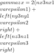
\\gamma xy=2(nx1nx2\\varepsilon 1)+\\left ( ny1ny2\\varepsilon 2 \\right )+\\left ( nz1nz2\\varepsilon 3 \\right )

Substituting the values of σ1, σ 2 and σ 3,

\\gamma xy= [\\lambda \\Delta\\left ( nx1nx2\\varepsilon 1+ny1ny2\\varepsilon 2+nz1nz2\\varepsilon 3 \\right )+\\left ( nx1nx2+ny1+ny2+nz1+nz3 \\right )]

τx’y’=μϒx’y’
Here, μ= shear modulus usually represented by term G.
By taking other axis as Oz¢ with direction cosines (nx3, ny3, nz3) and at right-angle with the Ox¢ and Oy¢. This Ox¢y¢z¢ will create conventional forms an orthogonal set of axes, therefore we can write as,

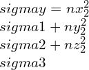
\\sigma y=nx_{2}^{2}\\sigma 1+ny_{2}^{2}\\sigma 2+nz_{2}^{2}\\sigma 3

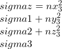
\\sigma z=nx_{3}^{2}\\sigma 1+ny_{3}^{2}\\sigma 2+nz_{3}^{2}\\sigma 3

\\sigma xy=(nx2nx3\\sigma 1)+\\left ( ny2ny3\\sigma 2\\right )+\\left ( nz2nz3\\sigma 3 \\right )

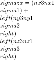
\\sigma zx=(nx3nx1\\sigma 1)+\\left ( ny3ny1\\sigma 2\\right )+\\left ( nz3nz1\\sigma 3 \\right )

strain components,

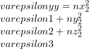
\\varepsilon yy=nx_{2}^{2}\\varepsilon 1+ny_{2}^{2}\\varepsilon 2+nz_{2}^{2}\\varepsilon 3

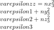
\\varepsilon zz=nx_{3}^{2}\\varepsilon 1+ny_{3}^{2}\\varepsilon 2+nz_{3}^{2}\\varepsilon 3

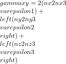
\\gamma xy=2(nx2nx3\\varepsilon 1)+\\left ( ny2ny3\\varepsilon 2 \\right )+\\left ( nz2nz3\\varepsilon 3 \\right )

\\gamma zx=2(nx3nx1\\varepsilon 1)+\\left ( ny3ny1\\varepsilon 2 \\right )+\\left ( nz3nz1\\varepsilon 3 \\right )

Elastic constants and their relations:

Young’s modulus E:


The young’s modulus is the measure of the stiffness of the body and acts as resistance of the material when the stress is functional. The young’s modulus is considered only for linear stress-strain behavior in the direction of stress.

E=\\frac{\\sigma }{\\varepsilon }

Poisson’s ratio (μ):


The Poisson’s ratio is the measure of the deformation of the material in the directions perpendicular to the loading. Poisson’s ratio ranges between -1 to 0.5 to maintain young’s modulus, shear modulus (G), bulk modulus positive.
μ=-\\frac{\\varepsilon trans}{\\varepsilon axial}

Bulk Modulus:

Bulk modulus K is the ratio of the hydrostatic pressure to the volumetric strain and better represented as
K=-v\\frac{dP}{dV}

E and n are generally taken as the independent constants and G and K could be stated as follows:

G=\\frac{E}{2(1+\\mu )}

K=\\frac{3\\lambda +2\\mu }{3}

for an isotropic material, Hooke’s law is reduced to two independent elastic constants named as Lame’s co-efficient denoted as l and m. In terms of these, the other elastic constants can be stated as follows.

If bulk modulus considered to be +ve the Poisson’s ratio never be more than 0.5 (maximum limit for incompressible material). For this case assumptions are
n = 0.5.
3G = E.
K = ∞.
⦁ In terms of principal stresses and principal strains:

\\sigma 1=\\lambda \\Delta +2\\mu \\varepsilon1

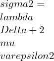
\\sigma 2=\\lambda \\Delta +2\\mu \\varepsilon2

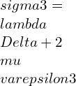
\\sigma 3=\\lambda \\Delta +2\\mu \\varepsilon3

\\varepsilon 1=\\frac{\\lambda +\\mu }{\\mu \\left ( 3\\lambda +2\\mu \\right )}[\\sigma 1-\\frac{\\lambda }{2\\left ( \\lambda +\\mu \\right )}\\left ( \\sigma 2+\\sigma 3 \\right )]

\\varepsilon 2=\\frac{\\lambda +\\mu }{\\mu \\left ( 3\\lambda +2\\mu \\right )}[\\sigma 2-\\frac{\\lambda }{2\\left ( \\lambda +\\mu \\right )}\\left ( \\sigma 3+\\sigma 1 \\right )]

\\varepsilon 1=\\frac{\\lambda +\\mu }{\\mu \\left ( 3\\lambda +2\\mu \\right )}[\\sigma 3-\\frac{\\lambda }{2\\left ( \\lambda +\\mu \\right )}\\left ( \\sigma 1+\\sigma 2 \\right )]

⦁ In terms of rectangular stress and strain components referred to an orthogonal coordinate system XYZ:

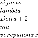
\\sigma x=\\lambda \\Delta +2\\mu \\varepsilonxx

\\sigma y=\\lambda \\Delta +2\\mu \\varepsilonyy

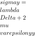
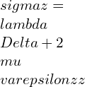
\\sigma z=\\lambda \\Delta +2\\mu \\varepsilonzz

\\varepsilon xx=\\frac{\\lambda +\\mu }{\\mu \\left ( 3\\lambda +2\\mu \\right )}[\\sigma x-\\frac{\\lambda }{2\\left ( \\lambda +\\mu \\right )}\\left ( \\sigma y+\\sigma z \\right )]

\\varepsilon yy=\\frac{\\lambda +\\mu }{\\mu \\left ( 3\\lambda +2\\mu \\right )}[\\sigma y-\\frac{\\lambda }{2\\left ( \\lambda +\\mu \\right )}\\left ( \\sigma x+\\sigma z \\right )]

\\varepsilon zz=\\frac{\\lambda +\\mu }{\\mu \\left ( 3\\lambda +2\\mu \\right )}[\\sigma z-\\frac{\\lambda }{2\\left ( \\lambda +\\mu \\right )}\\left ( \\sigma x+\\sigma y \\right )]

Young’s modulus vs shear modulus | relation between young’s modulus and modulus of rigidity

Elastic Constants Relations: Shear Modulus, Bulk Modulus, Poisson’s ratio, Modulus of Elasticity.

E=3K(1-2 μ)

E=2G(1+μ)

E= 2G(1+μ)=3K(1-2 μ)

Shear Modulus of Elasticity:

Hook’s law for shear stress:
τxy=G.ϒxy
where,
τxy is represented as Shear-stress, Shear-modulus is G and Shear strain is ϒxy respectively.
Shear-Modulus is resistant to the deformation of the material in response to shear stress.

Dynamic shear modulus of soil:

Dynamic shear modulus gives information about dynamic one. Static shear-modulus gives information about static one. These are determined using shear wave velocity and density of the soil.

11

Shear Modulus Formula soil

Gmax=pVs2

Where, Vs=300 m/s, ρ=2000 kg/m3, μ=0.4.

Effective shear modulus:

The ratio of the average stresses to average strains is the effective shear-modulus.

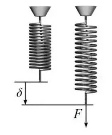
Modulus of rigidity of spring:

The modulus of rigidity of the spring is the measurement of the stiffness of the spring. It varies with the material and processing of the material.

For Closed Coil Spring:

delta =\\frac{64WR^{3}n}{Nd^{4}}

For Open Coil Spring:

\\delta =\\frac{64WR^{3}nsec\\alpha }{d^{4}}[\\frac{cos^{2}\\alpha }{N}+\\frac{2sin^{2}\\alpha }{E}]

Where,
R= mean radius of the spring.
n = number of coils.
d= diameter of the wire.
N= shear modulas.
W= load.
δ=deflection.
α= Helical angle of the spring.

Modulus of Rigidity- Torsion | Modulus of Rigidity Torsion test

The rate change of strain undergoing shear stress and is a function of stress subjected to torsion loading.

The main objective of the torsion experiment is to determine the shear-modulus. The shear stress limit is also determined using the torsion test. In this test, one end of the metallic rod is subjected to torsion, and the other end is fixed.
The shear strain is calculated by using the relative angle of twist and gauge length.
γ = c * φG / LG.
Here c – cross-sectional radius.
Unit of φG measured in radian.
τ = 2T/(πc3),

shear-stress is linearly proportionate to shear-strain, if we measured at the surface.

Frequently Asked Questions:


What are the 3 Modulus of elasticity?

Young’s modulus:

This is the ratio of longitudinal stress to longitudinal strain and could be better represented as

Young’s modulus ϒ= longitudinal stress/longitudinal strain.

Bulk Modulus:

The ratio of hydrostatic pressure to volume strain is called the Bulk modulus denoted as

Bulk Modulus(K)=volume stress/volume strain.

Modulus of Rigidity:

The ratio of shear stress to the shear strain of the material may well characterized as

Shear Modulus(η)=shear stress/shear strain.

Modulas of Rigidity


What does a Poisson ratio of 0.5 mean?

Passion’s ratio ranges between 0-0.5.at small strains, an incompressible isotropic elastic material deformation gives Poisson’s ratio of 0.5. Rubber has a higher bulk modulus than the shear-modulus and Poisson’s ratio nearly 0.5.

What is a high modulus of elasticity?

The modulus of elasticity measures the resistance of the material to the deformation of the body and if modulus increse then material required additional force for the deformation.

What does a high shear modulus mean?


A high shear-modulus means the material has more rigidity. a large amount of force is required for the deformation.


Why is shear modulus important?


The shear-modulus is the degree of the stiffness of the material and this analyze how much force is required for the deformation of the material.


Where is shear modulus used ?| What are the applications of rigidity modulus?

The Information’s of shear-modulus is used any mechanical characteristics analysis. For calculation of shear or torsion loading test etc.


Why is shear modulus always smaller than young modulus?

Young’s modulus is the function of longitudinal strain and shear modulus is a function of transverse strain. So, this gives the twisting in the body whereas young’s modulus gives the stretching of the body and Less force is required for twisting than stretching. Hence shear modulus is always smaller than the young’s modulus.

For an ideal liquid, what would be the shear modulus?

In ideal liquids shear strain is infinite, the shear modulus is the ratio of shear stress to the shear strain. So the shear modulus of ideal liquids is zero.

When the bulk modulus of a material becomes equal to the shear modulus what would be the Poisson’s ratio ?

As per the relation between bulk modulus, shear modulus and poissons ratio,
2G(1+μ)=3K(1-2 μ)
When, G=K
2(1+ μ)=3(1-2 μ)
2+2 μ=3-6 μ
8 μ=1
μ =1/8

Why the required shear stress to initiate dislocation movement is higher in BCC than FCC?

BCC structure has more shear stress values critical resolved than FCC structure.

What is the ratio of shear modulus to Young’s modulus if poissons ratio is 0.4, Calculate by considering related assumptions.

Answer.
2G(1+μ) =3K (1-2 μ)
2G (1+0.4) =3K(1-0.8)
2G(1.4) =3K(0.2)
2.8G=0.6K
G/K=0.214

Which has a higher modulus of rigidity a hallow circular rod or a solid circular rod ?

Modulus of rigidity is the ratio of shear stress to the shear strain and shear stress is the Force per unit area. Hence shear stress is inversely proportional to the area of the body. solid circular rod is stiffer and stronger than the hollow circular rod.

Modulus of Rigidity vs Modulus of Rupture:

The modulus of rupture is the fracture strength. It is the tensile strength of the beams, slabs, concrete, etc. Modulus of rigidity is the strength of material to be rigid. It is the stiffness measurement of the body.

If the radius of the wire is doubled how will the rigidity modulus vary? Explain your answer.

Modulus of rigidity does not vary by change of the dimensions and hence modulus of rigidity remains the same when the radius of the wire is doubled.

Coefficient of viscosity and modulus of rigidity:

The coefficient of viscosity is the ratio of the shear stress to the rate of shear strain which varies by the velocity change and displacement change and the modulus of rigidity is the ratio of shear stress to the shear strain where shear strain is due to transverse displacement.
The ratio of shear-modulus to the modulus of elasticity for a Poisson’s ratio of 0.25 would be
For this case we may consider that.
2G(1+μ)=3K(1-2 μ)
2G(1+0.25) =3K(1-0.5)
2G(1.25)=3K(0.5)

G/K=0.6
Answer = 0.6

What material has modulus of rigidity equal to about 0.71Gpa ?

Answer:
Nylon(0.76Gpa)
Polymers range between such low values.

For more Mechanical Engineering related article click here

Dual Cycle: 11 Important Factors Related To It

CodeCogsEqn 2023 02 03T212139.469

Content : Dual Cycle

What is Dual cycle?

Dual Combustion Cycle | Mixed cycle | Sabathe cycle

The dual cycle is named after The Russian-German engineer Gustav Trikler. It is also known as the mixed cycle, Trinkler cycle, seiliger cycle or sabathe cycle.

Dual cycle is a combination of constant volume Otto cycle and constant pressure diesel cycle. Heat addition takes place in two parts in this cycle. Partial heat addition takes place at constant volume similar to Otto cycle while the remaining Partial heat addition takes place at constant pressure similar to diesel cycle. The significance of such method of heat addition is it gives more time to fuel for complete combustion.

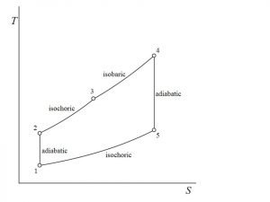
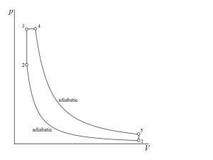
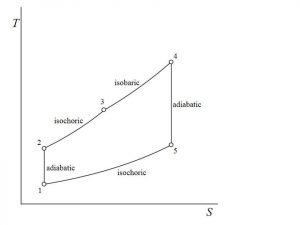
Dual cycle P-V Diagram | Dual cycle T-S Diagram

The dual cycle comprises of following operations:

  • Process 1-2 follows the reversible adiabatic or Isentropic compression
  • In Process 2-3 constant volume partial heat Addition takes place
  • In Process 3-4 constant pressure partial heat Addition takes place
  • Process 4-5 follows reversible adiabatic or isentropic expansion.
  • In Process 5-1 constant volume heat rejection takes place

Dual Cycle efficiency | Dual Cycle Thermal efficiency

The efficiency of dual cycle is given by

\\eta_{dual}=1-\\frac{1}{r_k^{\\gamma -1}}[\\frac{r_pr_c^\\gamma -1}{(r_p-1)+r_p\\gamma (r_c-1)}]

Where, rp = Pressure ratio = P3/P2

rk = compression ratio = V1/V2

rc = cutoff ratio = V4 /V3

re = expansion ratio = V5/V4

When rc = 1, The cycle becomes Otto cycle

rp = 1, the cycle becomes diesel cycle.

Dual cycle P-V and T-S diagram

Air standard dual cycle | Dual cycle efficiency derivation

The dual cycle comprises of following operations:

  • Process 1-2 follows the reversible adiabatic or Isentropic compression
  • In Process 2-3 constant volume partial heat Addition takes place
  • In Process 3-4 constant pressure partial heat Addition takes place
  • Process 4-5 follows reversible adiabatic or isentropic expansion.
  • In Process 5-1 constant volume heat rejection takes place

Total Heat supplied is given by

Q_s=mC_v [T_3-T_2 ]+mC_p [T_4-T_3]

Where Heat supplied at constant volume

Q_v= mC_v [T_3-T_2 ]

Where Heat supplied at constant pressure

Q_p= mC_p [T_4-T_3]

Heat rejected at constant volume is given by

Q_r= mC_v [T_5-T_1 ]

The efficiency of dual cycle is given by

\\eta=\\frac{(mC_v [T_3-T_2 ]+mC_p [T_4-T_3 ]-mC_v [T_5-T_1 ])}{(mC_v [T_3-T_2 ]+mC_p [T_4-T_3])}

\\\\\\eta=1-\\frac{(T_5-T_1)}{([T_3-T_2 ]+\\gamma[T_4-T_3])}\\\\\\\\ \\eta_{dual}=1-\\frac{1}{r_k^{\\gamma -1}}[\\frac{r_pr_c^\\gamma -1}{(r_p-1)+r_p\\gamma (r_c-1)}]

Where, rp = Pressure ratio = P3/P2

rk = compression ratio = V1/V2                 

rc = cutoff ratio = V4 /V3

re = expansion ratio = V5/V4

When rc = 1, the cycle becomes Otto cycle

rp = 1, the cycle becomes diesel cycle.

Mean effective pressure of dual cycle

The mean effective pressure of dual cycle is given by

M.E.P=\\frac{(P_1 [\\gamma r_p r_k^\\gamma (r_c-1)+r_k^\\gamma (r_p-1)-r_k (r_p r_c^\\gamma-1) ] )}{(\\gamma-1)(r_k-1) }

Where, rp = Pressure ratio = P3/P2

rk = compression ratio = V1/V2

rc = cutoff ratio = V4 /V3

re = expansion ratio = V5/V4

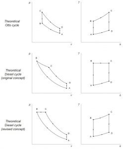
Otto Diesel Dual Cycle Diagram

Otto Diesel Duel cycle
Image Credit: Wikipedia Commons

Comparison between Otto, diesel and dual cycle

Case 1: For similar compression ratio and similar heat i/p this relationship will be

[Qin]otto = [Qin]Diesel.

[QR]otto< [QR]Diesel.

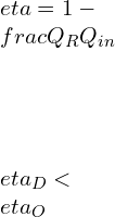
\\\\\\eta=1-\\frac{Q_R}{Q_{in}}\\\\\\\\ \\eta_D<\\eta_O

In this case of same compression ratio and equal heat input it will be

\\eta_D<\\eta_{dual}<\\eta_O

Case 2: In this case of, same compression ratio and same heat-rejection, this relationship will be

[Qin]otto> [Qin]Diesel.

[QR]otto= [QR]Diesel.

\\\\\\eta=1-\\frac{Q_R}{Q_{in}}\\\\\\\\ \\eta_D<\\eta_O

In this case of, same compression ratio and same heat-rejection.

\\eta_D<\\eta_{dual}<\\eta_O

Case 3: In this case of, same Maximum Temperature and same heat-rejection.

[QR]otto= [QR]Diesel

[Qin]Diesel>[Qin]otto

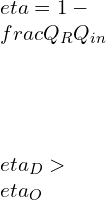
\\\\\\eta=1-\\frac{Q_R}{Q_{in}}\\\\\\\\ \\eta_D>\\eta_O

For same Maximum Temperature and same heat rejection

\\eta_D>\\eta_{dual}>\\eta_O

Dual fuel engine cycle | Mixed dual cycle

Dual Cycle Engine

Dual fuel engine works primarily on diesel cycle. The gaseous fuel [Natural gas] is introduced into the engine’s intake system through a supercharger at higher atmospheric pressure.

During the suction stroke, the leaner air-to-fuel ratio [air-to-natural gas mixture] is drawn into the cylinder, following the Otto cycle just as used in a spark-ignited engine. A small charge of pilot fuel is injected near the Top Dead Center and similar to CI engine it ignites near the end of the compression stroke, causing the secondary gas to burn. The combustion takes place smoothly and rapidly.

In dual-fuel engine pilot fuel and secondary fuel both burn simultaneously in a compression ignition engine. After the compression of secondary fuel at the suction stroke pilot fuel is used as a source of ignition.

The operating cost of this engine is lower than that of conventional diesel engine without compromising in delivery power, high torque and transient response.

Dual cycle application

  • Dual cycle is widely used for small propulsion engines and portable heavy duty machinery like drilling machines by companies like Cummins etc. The major reason of dual cycle being used in mobile equipment’s is it provides high power to mass ratio in comparison with Otto and diesel cycle.
  • They have wide range of application in aircraft and ships. Dual cycle engine are also called marine engine.

Advantage of dual cycle

  1. Higher heat yield – methane has the highest thermal output per unit mass of fuel, at 50,500kJ/kg methane burned compared to 44,390kJ heat/kg petrol burned or 43,896kJ heat/kg diesel burned. Many dual-combustion engines use natural gas whose primary content is methane as starter fuels because of its higher heat output.
  2. With a dual fuel combustion engine, two fuels must be purchased instead of one. This can help when the ship is low on both fuels, and the re-fueling location lacks one of the two fuels the engine takes in.
  3. A potential balance between clean fuel and economical storage – natural gas needs higher storage pressure and volume but offers better combustion efficiency. Diesel is easier to store (it’s a liquid oil) but does not burn as quickly for the same temperature and pressure as the other fuels. With a dual combustion engine, one can start the diesel engine then switch to natural gas when the combustion space is hot enough.

Dual Cycle problems and solutions

A C.I engine has a compression ratio of 10. The heat liberated at constant volume is 2/3 of total Heat while the remaining is liberated at constant pressure. The initial pressure and temperature is 1 bar and 27oC. Maximum cycle pressure is 40 bars. Find temperature at the end of compression and expansion. [PV1.35 = C, ϒ = 1.4]

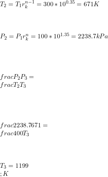
Solution: rk = 10, P1 = 1 bar = 100 kPa, T1=27 C = 300K, P3 = P4 = 40 bar, PV1.35 = C, ϒ = 1.4

\\\\T_2=T_1 r_k^{n-1}=300*10^{0.35}=671 K\\\\\\\\ P_2=P_1 r_k^n=100*10^{1.35}=2238.7 kPa\\\\\\\\ \\frac{P_2}{P_3}=\\frac{T_2}{T_3}\\\\\\\\ \\frac{2238.7}{671}=\\frac{400}{T_3}\\\\\\\\ T_3=1199\\;K

Heat input at constant volume

\\\\Q_v=C_v [T_3-T_2 ]=0.718*[1199-671]=379kJ/kg\\\\\\\\ (2/3)*Q=Q_v\\\\\\\\ Q=(3/2)*379=568.5 kJ/kg\\\\\\\\ C_p [T_4-T_3 ]=Q/3\\\\\\\\ 1.005*[T_4-1199]=568.5/3\\\\\\\\ T_4=1387.55 K

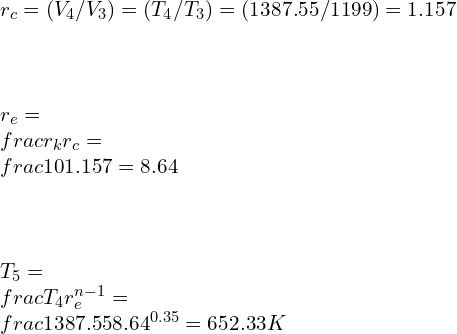
\\\\r_c=(V_4/V_3) =(T_4/T_3) =(1387.55/1199)=1.157\\\\\\\\ r_e=\\frac{r_k}{r_c} =\\frac{10}{1.157}=8.64\\\\\\\\ T_5=\\frac{T_4}{r_e^{n-1}} =\\frac{1387.55}{8.64^{0.35}} =652.33 K

An air standard dual cycle before compression air is at 100 kPa and 300K. During compression the volume changes from 0.07 m3 to 0.004m3. For constant pressure heat addition, the temperature varies from 1160 C to 1600C. Find the compression ratio; mean effective pressure and cut-off ratio for the cycle.

P1 = 100 kPa, T1=27 C = 300K

Compression ratio

r_k=[V_1/V_2] =[0.07/0.004]=17.5

T3 = 1160C = 1433 K, T4 = 1600 C = 1873 K

For isentropic compression process

\\\\P_1 V_1^\\gamma=P_2 V_2^\\gamma\\\\\\\\ P_2=P_1 r_k^{\\gamma}=100*17.5^{1.4}=5498.6 kPa\\\\\\\\ \\frac{T_2}{T_1}=r_k^{\\gamma -1}\\\\\\\\ T_2=300*17.5^{1.4-1}=942.6 K

Cut-off ratio

\\\\r_c=[T_4/T_3 ]=[1873/1433]=1.307\\\\\\\\ Also \\;\\\\\\\\ r_c=[V_4/V_3] =1.307\\\\\\\\ V_4=1.307*0.004=5.228*10^{-3} m^3

For isentropic expansion process

\\\\T_5/T_4 =[V_4/V_5] ^{\\gamma-1}\\\\\\\\ (T_5/1873)=[\\frac{(5.228*10^{-3})}{0.07}]^{1.4-1}\\\\\\\\ T_5=663.48 K

Total Heat Supplied

\\\\Q_s=C_v [T_3-T_2 ]+C_p [T_4-T_3 ]\\\\\\\\ Q_s=0.717*(1433-942.6)+1.005*(1873-1433)\\\\\\\\ Q_s=793.81 kJ

Heat rejected

\\\\Q_r=C_v (T_5-T_1)\\\\\\\\ Q_r=0.717*(663.45-300)=260.6 kJ

Work done is given by

W=Q_s-Q_r = 793.81-260.6 = 533.21 kJ

Mean effective pressure for dual cycle

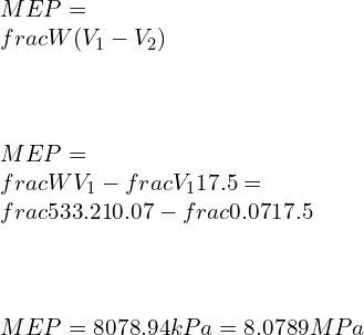
\\\\MEP=\\frac{W}{(V_1-V_2 )}\\\\\\\\ MEP=\\frac{W}{V_1-\\frac{V_1}{17.5}}=\\frac{533.21}{0.07-\\frac{0.07}{17.5}}\\\\\\\\ MEP=8078.94 kPa=8.0789 MPa

FAQ

Q.1) where is dual cycle used?

Ans: – Dual cycle is widely used for small propulsion engines and portable heavy duty machinery like drilling machines by companies like Cummins etc. The major reason of dual cycle being used in mobile equipments is it provides high power to mass ratio in comparison with Otto and diesel cycle.

They have wide range of application in aircraft and ships. Dual cycle engine are also called marine engine.

Q.2) what is the efficiency of dual cycle?

The efficiency of dual cycle is given by

\\eta_{dual}=1-\\frac{1}{r_k^{\\gamma -1}}[\\frac{r_pr_c^\\gamma -1}{(r_p-1)+r_p\\gamma (r_c-1)}]

Where, rp = Pressure ratio = P3/P2

rk = compression ratio = V1/V2

rc = cutoff ratio = V4 /V3

re = expansion ratio = V5/V4

When rc = 1, The cycle becomes Otto cycle

rp = 1, the cycle becomes diesel cycle.

Q.3) what are the importance of dual cycle in the diesel engine operations?

Dual fuel engine works primarily on diesel cycle. The gaseous fuel [Natural gas] is introduced into the engine’s intake system through a supercharger at higher atmospheric pressure.

During the suction stroke, the leaner air-to-fuel ratio [air-to-natural gas mixture] is drawn into the cylinder, following the Otto cycle just as used in a spark-ignited engine. A small charge of pilot fuel is injected near the Top Dead Center and similar to CI engine it ignites near the end of the compression stroke, causing the secondary gas to burn. The combustion takes place smoothly and rapidly.

In dual-fuel engine pilot fuel and secondary fuel both burn simultaneously in a compression ignition engine. After the compression of secondary fuel at the suction stroke pilot fuel is used as a source of ignition.

The operating cost of this engine is lower than that of conventional diesel engine without compromising in delivery power, high torque and transient response.

Q.4) why is the dual cycle known as a mixed cycle?

Dual fuel engine works primarily on diesel cycle. The gaseous fuel [Natural gas] is introduced into the engine’s intake system through a supercharger at higher atmospheric pressure.

During the suction stroke, the leaner air-to-fuel ratio [air-to-natural gas mixture] is drawn into the cylinder, following the Otto cycle just as used in a spark-ignited engine. A small charge of pilot fuel is injected near the Top Dead Center and similar to CI engine it ignites near the end of the compression stroke, causing the secondary gas to burn. The combustion takes place smoothly and rapidly.

In dual-fuel engine pilot fuel and secondary fuel both burn simultaneously in a compression ignition engine. After the compression of secondary fuel at the suction stroke pilot fuel is used as a source of ignition.

The operating cost of this engine is lower than that of conventional diesel engine without compromising in delivery power, high torque and transient response.

Q.5) what is cut off ratio in dual cycle?

The cut-off ratio for dual cycle is given by

rc = cutoff ratio = V4 /V3

Where, V4 = volume after partial heat addition at constant pressure

V3 = volume after partial heat addition at constant volume

Q.6) What is Dual cycle P-V and T-S diagram ?

To see the answer Click here

Q.7) Dual cycle solved example.

A C.I engine has a compression ratio of 10. The heat liberated at constant volume is 2/3 of total Heat while the remaining is liberated at constant pressure. The initial pressure and temperature is 1 bar and 27oC. Maximum cycle pressure is 40 bars. Find temperature at the end of compression and expansion. [PV1.35 = C, ϒ = 1.4]

Solution: rk = 10, P1 = 1 bar = 100 kPa, T1=27 C = 300K, P3 = P4 = 40 bar, PV1.35 = C, ϒ = 1.4

\\\\T_2=T_1 r_k^{n-1}=300*10^{0.35}=671 K\\\\\\\\ P_2=P_1 r_k^n=100*10^{1.35}=2238.7 kPa\\\\\\\\ \\frac{P_2}{P_3}=\\frac{T_2}{T_3}\\\\\\\\ \\frac{2238.7}{671}=\\frac{400}{T_3}\\\\\\\\ T_3=1199\\;K

Heat input at constant volume

\\\\Q_v=C_v [T_3-T_2 ]=0.718*[1199-671]=379kJ/kg\\\\\\\\ (2/3)*Q=Q_v\\\\\\\\ Q=(3/2)*379=568.5 kJ/kg\\\\\\\\ C_p [T_4-T_3 ]=Q/3\\\\\\\\ 1.005*[T_4-1199]=568.5/3\\\\\\\\ T_4=1387.55 K

\\\\r_c=(V_4/V_3) =(T_4/T_3) =(1387.55/1199)=1.157\\\\\\\\ r_e=\\frac{r_k}{r_c} =\\frac{10}{1.157}=8.64\\\\\\\\ T_5=\\frac{T_4}{r_e^{n-1}} =\\frac{1387.55}{8.64^{0.35}} =652.33 K

An air standard dual cycle before compression air is at 100 kPa and 300K. During compression the volume changes from 0.07 m3 to 0.004m3. For constant pressure heat addition, the temperature varies from 1160 C to 1600C. Find the compression ratio; mean effective pressure and cut-off ratio for the cycle.

P1 = 100 kPa, T1=27 C = 300K

Compression ratio

r_k=[V_1/V_2] =[0.07/0.004]=17.5

T3 = 1160C = 1433 K, T4 = 1600 C = 1873 K

For isentropic compression process

\\\\P_1 V_1^\\gamma=P_2 V_2^\\gamma\\\\\\\\ P_2=P_1 r_k^{\\gamma}=100*17.5^{1.4}=5498.6 kPa\\\\\\\\ \\frac{T_2}{T_1}=r_k^{\\gamma -1}\\\\\\\\ T_2=300*17.5^{1.4-1}=942.6 K

Cut-off ratio

\\\\r_c=[T_4/T_3 ]=[1873/1433]=1.307\\\\\\\\ Also \\;\\\\\\\\ r_c=[V_4/V_3] =1.307\\\\\\\\ V_4=1.307*0.004=5.228*10^{-3} m^3

For isentropic expansion process

\\\\T_5/T_4 =[V_4/V_5] ^{\\gamma-1}\\\\\\\\ (T_5/1873)=[\\frac{(5.228*10^{-3})}{0.07}]^{1.4-1}\\\\\\\\ T_5=663.48 K

Total Heat Supplied

\\\\Q_s=C_v [T_3-T_2 ]+C_p [T_4-T_3 ]\\\\\\\\ Q_s=0.717*(1433-942.6)+1.005*(1873-1433)\\\\\\\\ Q_s=793.81 kJ

Heat rejected

\\\\Q_r=C_v (T_5-T_1)\\\\\\\\ Q_r=0.717*(663.45-300)=260.6 kJ

Work done is given by

W=Q_s-Q_r = 793.81-260.6 = 533.21 kJ

Mean effective pressure for dual cycle

\\\\MEP=\\frac{W}{(V_1-V_2 )}\\\\\\\\ MEP=\\frac{W}{V_1-\\frac{V_1}{17.5}}=\\frac{533.21}{0.07-\\frac{0.07}{17.5}}\\\\\\\\ MEP=8078.94 kPa=8.0789 MPa

To know about Polytropic Process (click here)and Prandtl Number (Click here)

Op Amp: 7 Important Parameters

1280px Op amp symbol.svg 300x255 1

Points of Discussion

Structures, PIN outs & Schematic

Op amp diagram

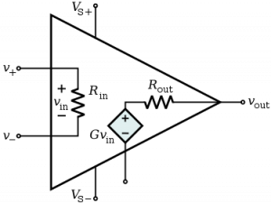
The op-amp diagram marks the inputs, outputs, and saturation voltage connections. It is an open-loop system. The below image represents an op-amp diagram.

Op amp pinout

In-general typical op-amp ICs have eight pins. Seven are functional, while one pin is dedicated for output. It takes four inputs; 2 of them are for inverting terminal and non-inverting terminal, and the rest 2 are for positive and negative saturation voltage. The pinout of IC741 is given above.

Op amp schematic

The below image gives a schematic view of an op-amp.

Op amp
Schematic Diagram by: InductiveloadOp-Amp Internal, marked as public domain, more details on Wikimedia Commons

As we can see in the image, an op-amp consists of transistors and resistors. The input impedance is high because of the Darlington pair of the NPN transistors. There are two differential gain stages, and the output is taken from the single-ended emitter follower. The transistors T1 and T2 are identical, and so as the T3 and T4.


Types and Applications

Op amp applications | Op amp uses

Op-amps are one of the essential elements for circuit designing in electronics. They are used in various places. Some of the examples are –

Unity gain buffer, phase shift oscillator, current to voltage follower, the voltage to a current follower, summing amplifier, integrator, differentiator, half-wave rectifier, peak detector, etc. There are many more applications of the op-amp. Almost every electronic gadget is incorporated with an op-amp.

High pass filter op amp

A high pass filter can be built using an RC filter circuit and a typical op-amp. Combining a passive RC filter with op-amp functions like an active high pass filter. The inverting or non-inverting terminal operation of the op amp is required for the circuit. The below image represents a high pass filter op amp circuit.

Op amp bandpass filter

A bandpass filter allows a signal of the specified frequency range only. This filter filters out other components of frequencies. Op-amps are used to make such types of filters. The circuit is designed by cascading a high pass filter with an op-amp and then a low pass filter.

Subtractor op amp

Subtractor op-amp amplifies the difference between the two input voltages and provides that as output. It performs the subtraction operation, unlike a summing amplifier which adds up the input voltages. That is why it is known as subtractor op-amp.

Op amp adder

Op-amp adder or summing amplifier is the amplifier that amplifies the summation of the input voltages and provides as output. It performs summation or addition operation, unlike a differential amplifier which performs subtraction operations. The circuit diagram is given above.

Unity Gain op amp

A unity gain op-amp or a voltage follower circuit, or a buffer circuit is a specially designed non-inverting amplifier model. Observe the circuit of the non-inverting amplifier given above. If we made the feedback resistance zero and the inverting terminal infinite resistance, the amplifier’s gain would be unity. That is why this circuit is known as unity gain op-amp or unity gain buffer. This buffer is used for impedance matching.

Op amp oscillator

It is also possible to create an oscillator using an op-amp. The below-given image represents the circuit diagram of a phase shift RC oscillator.

Op amp
Oscillator, By: Jontse at English WikipediaOpAmpHystereticOscillator, marked as public domain, more details on Wikimedia Commons

After some general calculations, we have found out that oscillation frequency is f = 1/ (2πRC -/6) and the voltage gain Av = -29 for sustained oscillation.

Audio op amp

Operational amplifiers are heavily used in audio processing and audio mixers. An op-amp can amplify weak voice signals. Several types of audio op-amps are available in the market. Some of them are – LT1115, UA741, etc.

Op amp level shifter

In a single supply op-amp, the op-amp can level shift a ground-referenced signal. A level shifter can translate logic signals from one level to another. Sometimes there is a need for converting a positive to negative signal into an acceptable range for a single supply analog to digital converter.

Op amp voltage divider

Op-amps are also used as a voltage divider. Op-amp is used to make voltage dividers as using op-amp can increase the system’s gain.

Single supply op amp

Single supply op amp is such a special op-amp with only one supply terminal. The supply terminal is typically the +Vcc. So, the output lies between the range of +Vcc and the ground (GND) for an input signal.

High Voltage op amp

A high voltage amplifier is typically used to amplify the input signal to a high voltage output signal. It can provide the power gain at the voltage and current combinations. Some of the high voltage op-amps applications are – inkjet printers, ultrasound transducer, Geiger counters, biomedical tests, etc.

For Detail Circuit Analysis of Circuits… Click Here!

Various kinds of IC

45588 op amp

It is another integrated circuit that operates op-amp. It is a high-performance eight-pin IC that doesn’t need any external frequency compensator components. Some of the other models are – CF158MT, AN45588, LA6458, etc.

lm358 op amp

lm358 is another type of IC that consists of a couple of op-amps. It is a low-power IC, which National Semiconductor first developed.

ua741 op amp

This is another type of IC that includes an operational amplifier. It has eight pins. The maximum supply voltage is +18V, and the maximum differential input voltage is +15V. The CMMR is 90 dB. UA 741 is used in audio applications, music players.

Lm324 op amp

Lm324 is a specially built IC, which can function as an amplifier, comparator, rectifier, etc. This IC has 14 pins, representing four op-amps. It has a wide bandwidth of around 1 MHz and a gain of 100 dB. They are applied in various fields of robotics, oscillators, etc.

Ne5532 op amp

Another IC of the op-amp is ne5532. It is a high-performance amplifier that has excellent DC and AC voltages. It has low noise, maximum output swing bandwidth, and a high slew rate. Different variations of this type of ICs are – NE5532A, SA55332, etc.

Important Parameters, Rules, Equations

Op amp circuit analysis

The op-amp circuit analysis reveals the functionality of each part of an op-amp and how they are connected or interconnected to provide the output path. Circuit analysis of op-amp can be classified into two types –

  1. open-loop circuit analysis
  2. closed-loop circuit analysis.

The open-loop circuit analysis analyzes the system without the feedback system, and the closed-loop circuit analysis is the analysis of a circuit with a feedback system.

The concept of virtual ground, high input impedance, and infinite gain are necessary for the op-amp circuit analysis.

Op amp golden rules

One op-amp designer should always keep in mind some essential rules. They are –

  1. Op amp provides infinite gain.
  2. The input impedances are high.
  3. No current flows through the op-amp at the beginning.
  4. The offset voltage is adjusted to make it zero.

Op amp formulas

There are no hard and fast formulas for the op-amp. There are several types of op-amps, and they have their specific equations and formulas. Like – formulas for output of Non inverting op amp: V0 = [ 1 + (Rf/R1)] * Vin and formulas for output of Inverting op amp: V0 = – (Rf/R1) * Vin

Input impedance of op amp

The input impedance is high because of the Darlington pair of the NPN transistors. For an ideal op-amp, the input impedance is infinite. Due to the high input impedance, we can assume that the current flows through the feedback at the beginning stage. Typically, the values are in between 1 megaohm to 10 tera ohms.

Output impedance of an op amp

Output impedance of op-amp referrers to the impedance provided by an op-amp at the output stage. An ideal has an output impedance of 0 ohms. The output driver circuit causes the output impedance of an op-amp.

Open loop gain of op amp

Open loop gain of an op-amp is the device’s gain when there is no feedback associated with it. For an ideal op-amp, the open-loop gain is infinite. A typical open-loop gain of the typical op-amp is around 100 dB.

Op amp offset voltage

An op-amp’s offset voltage is defined as the differential DC voltage between the input terminals. For an ideal op-amp, the offset voltage is zero. But for the practical op-amp, the external voltage is given to the op-amp.

Slew rate of op amp

Slew rate of the op-amp is the rate of change of the output signal if there is a step-change in the input signal. It is a parameter for the measurement of performance. The unit of slew rate is V/ ms. For an ideal op-amp, the slew rate is zero. It means that the input change will be reflected immediately in the output. For a typical practical op-amp, the slew rate value is 10 V / μs.

Op amp bandwidth

The bandwidth of an amplifier is referred to as the range of frequency above which the gain of the amplifier is higher than 3 dB. For a 741 MHz amplifier, the closed-loop amplifier is 1 MHz.

Op amp current source

An external current source with an op-amp provides a load resistance independent current. And as we have previously grounded the circuit, there is no chance of exposing two connections.

Op amp transfer functions

It is possible to obtain transfer functions of op-amp if the op-amps are represented in a classical feedback block diagram. Using the process of superposition, the transfer function can be obtained. The transfer function for the non-inverting terminal can be written as R1 / (R1 +Rf).

Op amp saturation

There is two input terminals, which takes positive and negative saturation voltages. Now, when an op-amp is in saturation, it means that the op-amp’s output is any of the saturation voltage provided from the supply.

How does an op amp work?

An op-amp typically goes through three stages of operations. The first one – differential input stage with higher input impedance, the gain stage in the second stage, and the push-pull output stage of lower output impedance.

What does an op amp do?

An op-amp or operational amplifier is an electronics device that performs certain mathematical operations and amplifies the input signal.

Otto Cycle | Its Important Relations and Formulas

Slide1 300x225 1

The Otto Cycle, fundamental to gasoline engines, consists of four strokes: intake, compression, power, and exhaust. It achieves thermal efficiency up to 25-30%. The compression ratio, typically between 8:1 and 12:1, directly influences efficiency and power output.

Otto Cycle Definition

“An Otto cycle is an ideal thermodynamic cycle that explains the working of a typical spark ignition piston engine and this cycle specifically explains, what happens if mass of gas is subjected to changes due to pressure, temp, volume, heat input, and release of heat.”

The Otto cycle engine | Valve timing diagram

  1. Inlet valve opens at 5-100 before the Top Dead Center. This is to ensure that the inlet should open fully when piston reaches at TDC and fresh charge start entering to cylinder as early as possible after TDC.
  2. Suction valve close at 20 – 300 after Bottom dead center BDC to take the advantage of momentum of moving gases.
  3. The spark takes place 30 – 400 before TDC. This is to allow time delay between spark and completion of combustion.
  4. Pressure at the end of power stroke is above atmospheric which increases the work to expel the exhaust gases. So exhaust valve opens at 20 – 300 before BDC so that at BDC pressure reduces to atmospheric pressure and useful work can be saved.
  5. The exhaust valve closes at 15 – 200 after TDC so that inertia of exhaust gas has a tendency to to scavenge the cylinder which will increase volumetric efficiency.

Otto cycle efficiency | thermal efficiency of Otto Cycle Formula

The efficiency of Otto cycle is specified by

\\eta =1-\\frac{1}{r^{\\gamma-1}}

Where r = compression ratio.

Otto Cycle diagram

Otto cycle P-V diagram | Otto cycle T-S diagram

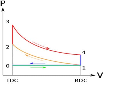
Otto cycle PV diagram
P-V diagram
Otto cycle TS diagram
T-S diagram

Otto, Diesel and Dual cycle | Comparison

Case 1: For similar compression ratio and similar heat i/p this relationship will be

[Qin]otto = [Qin]Diesel.

[QR]otto< [QR]Diesel.

\\\\\\eta=1-\\frac{Q_R}{Q_{in}}\\\\\\\\ \\eta_D<\\eta_O

In this case of same compression ratio and equal heat input it will be

\\eta_D<\\eta_{dual}<\\eta_O

Case 2: In this case of, same compression ratio and same heat-rejection, this relationship will be

[Qin]otto> [Qin]Diesel.

[QR]otto= [QR]Diesel.

\\\\\\eta=1-\\frac{Q_R}{Q_{in}}\\\\\\\\ \\eta_D<\\eta_O

In this case of, same compression ratio and same heat-rejection.

\\eta_D<\\eta_{dual}<\\eta_O

Case 3: In this case of, same Maximum Temperature and same heat-rejection.

[QR]otto= [QR]Diesel

[Qin]Diesel>[Qin]otto

\\\\\\eta=1-\\frac{Q_R}{Q_{in}}\\\\\\\\ \\eta_D>\\eta_O

For same Maximum Temperature and same heat rejection

\\eta_D>\\eta_{dual}>\\eta_O

Compression ratio of Otto cycle

Compression ratio of Otto cycle is defined as the ratio of volume before expansion to volume after expansion

r=\\frac{V_s+V_c}{V_s}=\\frac{V_1}{V_2}

Where Vs = Swept volume of cylinder

Vc = Clearance volume of the cylinder

In this cycle Compression ratio is generally 6 – 10. It is limited to 10 because of knocking in the engine.

Mean effective pressure formula for Otto cycle

Usually Pressure inside the cylinder on an IC engine is continuously changing; mean effective pressure is an imaginary pressure which is assumed to be constant throughout the process.

P_m=\\frac{P_1 r(r_p-1)(r^{\\gamma-1}-1)}{(\\gamma-1)(r-1)}

Where rp = Pressure ratio = P3/P2 = P4/P1

Otto cycle analysis | Otto cycle calculations | Otto cycle efficiency derivation

 Consider an air standard Otto cycle with initial Pressure, Volume and temperature as P1, V1, T1 respectively.

Otto cycle PV diagram
Otto cycle TS diagram
T-S diagram

Process 1-2: Reversible adiabatic compression.

\\frac{T_2}{T_1}=[\\frac{V_1}{V_2}]^{\\gamma-1}

Where,

r is the compression ratio.

Process 2 -3: Heat addition at constant Volume is calculated as,

Qin = m Cv [T­3-T2].

Process 3-4: Reversible adiabatic expansion is calculated as

\\frac{T_3}{T_4}=[\\frac{V_4}{V_3}]^{\\gamma-1}=r^{\\gamma-1}

Process 4 -1: Heat-rejection at constant Volume will be

QR = m Cv [T­4-T1]

Work done = Qin – QR.

Efficiency of the Otto cycle is represented as.

\\eta=1-\\frac{Q_R}{Q_{in}}

\\\\\\eta=1-\\frac{[T_4-T_1]}{[T_3-T_2]}\\\\\\\\ \\frac{T_2}{T_1}=\\frac{T_3}{T_4}\\\\\\\\ \\frac{T_4}{T_1}=\\frac{T_3}{T_2}\\\\\\\\ \\eta=1-\\frac{1}{r^{\\gamma-1}}

Where r = compression ratio.

Working of Two stroke Engine

Two strokes’ engines work on both Otto cycle as well as diesel cycle.

Atkinson cycle vs Otto cycle

Atkinson CycleOtto cycle
Atkinson cycle uses slightly different valve timing diagram. The Inlet valve remains open till the start of compression strokeInlet valve opens at 5-100 before the Top Dead Center. This is to ensure that the inlet should open fully when piston reaches at TDC and fresh charge start entering to cylinder as early as possible after TDC.
Provides higher fuel economy as compared to Otto cycle.Provides Lower fuel economy as compared to Atkinson cycle.
Provides Lower peak power as compared to Otto cycle.Provides higherPeak power as compared to Atkinson cycle.
Mostly used in Hybrid vehicles where electric motor compensates the power deficiency.Mostly used in 4-stroke and 2 – stroke SI engine where higher power is required
dual
Dual Cycle P-V diagram

Brayton cycle vs Otto cycle

Brayton CycleOtto cycle
Constant Pressure Heat addition and heat rejection takes place in Brayton cycle.Constant volume Heat addition and heat rejection takes place in Otto cycle.
It has capabilities to handle large volume of low-pressure gas.Not capable of handling large volume of low-pressure gas due to restriction in reciprocating engine space.
High temperature is experienced throughout the steady state flow process.High temperature is experienced by the engine only during Power stroke.
Suitable for gas turbineSuitable for IC and SI engine.

Advantages and Disadvantages of Otto cycle engine

Advantages:

  • This cycle has more thermal efficiency in comparison to diesel and dual cycle for identical compression ratio and equal heat input rate and same compression ratio and same heat rejection.
  • This cycle engine required less maintenance and are simple and light-weight in design.
  • For complete combustion pollutant emissions are low for Otto engines.

Disadvantages:

  • Has lower compression ratio thus it is Poor at moving heavy loads at low speed.
  • Will not be able to withstand higher stresses and strains as compared with diesel engine

Example of Otto cycle | Otto cycle problems

Q.1] A spark Ignition engine designed to have a compression ratio of 10. This is operating at low temperature and pressure at value 2000C and 200 kilopascals respectively. If Work O/P is 1000 kilo-Joule/kg, compute maximum possible efficiency and mean effective pressure.

Efficiency of this cycle is given by

\\eta =1-\\frac{1}{r^{\\gamma-1}}

Where r = compression ratio = 10

\\eta =1-\\frac{1}{10^{1.4-1}}=0.602=60.2\\%

For compression process

\\frac{T_2}{T_1}=r^{\\gamma-1}

\\frac{T_2}{473}=10^{1.4-1}

T_2=1188 \\;K

For expansion process, we can assume that

\\frac{T_3}{T_4}=r^{\\gamma-1}

\\frac{T_3}{T_4}=10^{1.4-1}

T_3=2.512T_4

Net work done can be computed by the formula

W=C_v [T_3-T_2 ]-C_v [T_4-T_1]

\\\\1000=0.717*[473-1188+T_3-T_4]\\\\\\\\ 1000=0.717*[473-1188+2.512 T_4-T_4]\\\\\\\\ T_4=1395 K

T_3=2.512*1395=3505 K

According to ideal gas theory, we know

P1v1 = RT1

v1=(RT1)/(P1)=(0.287*473)/200=0.6788 m3/kg

mep=\\frac{W}{v_1-v_2}=\\frac{1000}{0.6788-\\frac{0.6788}{10}}=1636.87\\;kPa

Q.2] what will be the effect on the efficiency of an Otto cycle having a compression ratio 6, if Cv increases by 20%. For the purpose of calculation Assume, that  Cv is 0.718 kJ/kg.K.

\\\\\\frac{\\mathrm{d} C_v}{C_v}=0.02\\\\\\\\ \\eta=1-\\frac{1}{r^{\\gamma -1}}=1-\\frac{1}{6^{1.4 -1}}=0.511\\\\\\\\ \\gamma -1=\\frac{R}{C_v}\\\\\\\\ \\eta=1-[\\frac{1}{r}]^\\frac{R}{C_v}

Taking log on both sides

ln(1-\\eta)=\\frac{R}{C_v} ln\\frac{1}{r}

Differentiating both sides

\\\\\\frac{d\\eta}{1-\\eta}=\\frac{-R}{C_v^2}*dC_v*ln[1/r]\\\\\\\\ \\frac{d\\eta}{1-\\eta}=\\frac{-R}{C_v}*\\frac{dC_v}{C_v}*ln[1/r]\\\\\\\\ \\frac{d\\eta}{\\eta}=\\frac{1-\\eta}{\\eta}*\\frac{-R}{C_v}*\\frac{dC_v}{C_v}*ln[1/r]\\\\\\\\ \\frac{d\\eta}{\\eta}=\\frac{1-0.511}{0.511}*\\frac{-0.287}{0.718}*0.02*ln[1/6]\\\\\\\\ \\frac{d\\eta}{\\eta}=-0.0136\\\\\\\\ \\frac{d\\eta}{\\eta}*100=-0.0136*100=-1.36\\%

I.e. If Cv increases by 2% then η decrease by 1.36%.

Frequently Asked Questions

What is the difference between Otto and Diesel cycle?

In Otto cycle heat addition takes place at constant volume while in diesel cycle, heat addition at constant pressure takes place and  Otto-cycle has lower compression ratio below 12 while, diesel cycle has higher compression ratio up to 22.  Otto-cycle uses spark plug for ignition while diesel cycle needs no assistance for ignition. Otto-cycle has lower efficiency as compared to diesel cycle.

Which fuel is used in Otto cycle ? | What is 4-stroke fuel?

Generally Petrol or gasoline mixed with 3-5% ethanol is used in Otto engine. In air standard Otto-cycle, air is assumed to be as a fuel.

Which is more efficient Otto or Diesel cycle?

The normal range of compression ratio for diesel cycle is 16-20 while in Otto-cycle compression ratio is 6 – 10 and due to higher compression ratio used in diesel cycle, the efficiency of diesel cycle is greater than Otto-cycle.

How does Otto cycle works?

  1. Inlet valve opens at 5-100 before the Top Dead Center. This is to ensure that the inlet should open fully when piston reaches at TDC and fresh charge start entering to cylinder as early as possible after TDC.
  2. Suction valve close at 20 – 300 after Bottom dead center BDC to take the advantage of momentum of moving gases.
  3. The spark takes place 30 – 400 before TDC. This is to allow time delay between spark and completion of combustion.
  4. Pressure at the end of power stroke is above atmospheric which increases the work to expel the exhaust gases. So exhaust valve opens at 20 – 300 before BDC so that at BDC pressure reduces to atmospheric pressure and useful work can be saved.
  5. The exhaust valve closes at 15 – 200 after TDC so that inertia of exhaust gases tends to scavenge the cylinder which will increase volumetric efficiency.

Process 1-2: Reversible adiabatic compression

\\frac{T_2}{T_1}=[\\frac{V_1}{V_2}]^{\\gamma-1}=r^{\\gamma-1}

Where r = compression ratio

Process 2 -3: Heat additions at constant Volume

Qin = m Cv [T­3-T2]

Process 3-4: Reversible adiabatic expansion

\\frac{T_3}{T_4}=[\\frac{V_4}{V_3}]^{\\gamma-1}=r^{\\gamma-1}

Process 4 -1: Heat-rejection at constant Volume will be

QR = m Cv [T­4-T1]

Work done = Qin – QR.

Efficiency of the Otto-cycle is represented as.

\\eta=1-\\frac{Q_R}{Q_{in}}

\\\\\\eta=1-\\frac{[T_4-T_1]}{[T_3-T_2]}\\\\\\\\ \\frac{T_2}{T_1}=\\frac{T_3}{T_4}\\\\\\\\ \\frac{T_4}{T_1}=\\frac{T_3}{T_2}\\\\\\\\ \\eta=1-\\frac{1}{r^{\\gamma-1}}

Where r = compression ratio.

Difference between Otto cycle Diesel cycle and Dual cycle

Otto cycle vs Dual cycle

dvs 2

Otto cycle vs Carnot cycle

Carnot CycleOtto cycleIt consists of two reversible isothermal process and two reversible adiabatic processes.Ideal air standard Otto-cycle consists of two Isochoric process and two reversible adiabatic processes.
 It is a hypothetical cycle and is not practically possible to construct.It is a real cycle and is the basis of working of modern Spark ignition engine.
It serves as a yardstick to measure the performance of other engine cycles.It does not serve as a yardstick to measure the performance of other engine cycles.
It has 100% efficiency.It has overall thermal efficiency in the range of 50 – 70 %.
It can be reversed to obtain Carnot refrigeration / heat pump with maximum coefficient of performance.It is a non-reversible cycle.

Otto cycle vs Atkinson cycle

Atkinson CycleOtto cycle
Atkinson cycle uses slightly different valve timing diagram. The Inlet valve remains open till the start of compression strokeInlet valve opens at 5-100 before the Top Dead Center. This is to ensure that the inlet should open fully when piston reaches at TDC and fresh charge start entering to cylinder as early as possible after TDC.
Provides higher fuel economy as compared to Otto-cycle.Provides Lower fuel economy as compared to Atkinson cycle.
Provides Lower peak power as compared to Otto- cycle.Provides higher Peak power as compared to Atkinson cycle.
Mostly used in Hybrid vehicles where electric motor compensates the power deficiency.Mostly used in 4-stroke and 2 – stroke SI engine where higher power is required

Otto cycle formula

The efficiency of Otto-cycle is given by the equation

\\eta =1-\\frac{1}{r^{\\gamma-1}}

Where r = compression ratio = 10

Otto cycle with polytropic process example

An SI engine has a compression ratio 8 while operating with low temperature of 3000C and a low pressure of 250 kPa. If Work o/p is 1000 kilo-Joule/kg, then compute highest efficiency. The compression and expansion takes place polytropically with polytropic index (n = 1.33).

Solution: The efficiency of Otto- cycle is given by the equation

\\eta =1-\\frac{1}{r^{\\gamma-1}}

Here γ = n

\\eta =1-\\frac{1}{r^{n-1}}=1-\\frac{1}{8^{1.33-1}}=49.65\\%

Why the Otto cycle is known as a constant volume cycle?

For this cycle, heat-addition and rejection happens at the fixed volume and the amount of work done is proportionate on heat addition and heat rejection rate, because of this reason Otto-cycle is termed as constant volume cycle.

What are the limitations of the Otto cycle?

  • It has lower compression ratio thus it is Poor at moving heavy loads at low speed.
  • Cannot withstand higher stresses and strains as compared with diesel engine.
  • Overall fuel efficiency is lower than diesel cycle.

Are two stroke engines considered to be Otto cycle engines?

Two strokes engines work on both Otto-cycle as well as diesel cycle. The working of 2-stroke engine is given below:

  1. Piston moves down and useful power is obtained. The downward motion of piston compresses the fresh charge stored in crankcase.
  2. Near the end of expansion stroke, the piston will reveal the exhaust-port at first. Then the cylinder pressure will drop to atmospheric pressure as during that time combustion materialwill leave from the cylinder.
  3. Further motion of piston reveals the transfer port allowing the slightly compressed charge in crank case to be entered the engine’s cylinder.
  4. Projection in piston prevents the fresh charge from passdirectly to the exhaust port and scavenging the combustion materials.
  5. When piston move up from bottom dead centre to top dead center and the transfer port closes at first then exhausts port will close and compression will happen. At the same time vacuum is created in crankcase and fresh charge enter into crankcase for next cycle.

Why is the Atkinson cycle more efficient even though it produces lower compression and pressure than the Otto cycle?

In Atkinson cycle, for isentropic expansion process in Otto cycle is further allowed to proceed and extend to lower cycle pressure in order to increase the work output and we know that efficiency increases for increase in work produced. That is, why the Atkinson cycle is more efficient even though it produces lower compression and pressure than the Otto cycle.

What is the compression ratio of the Otto cycle

Compression ratio of this cycle is elaborated  as

r=\\frac{V_s+V_c}{V_s}=\\frac{V_1}{V_2}

Where,

Vs = Swept volume of cylinder.

Vc = Clearance volume of the cylinder.

Generally in Otto cycle compression ratio is 6 – 10. It is limited to 10 because of knocking in the engine.

Otto cycle vs diesel cycle efficiency

The normal range of compression ratio for diesel cycle is 16-20 while in Otto cycle compression ratio is 6 – 10 and for more compression ratio used in diesel cycle, the efficiency of diesel cycle is greater than Otto cycle.

Case 1: For same compression ratio and exactly identical heat input, the relationship will be

[Qin]otto = [Qin]Diesel.

[QR]otto< [QR]Diesel.

\\\\\\eta=1-\\frac{Q_R}{Q_{in}}\\\\\\\\ \\eta_D<\\eta_O

In this case of same compression ratio and equal heat input it will be

\\eta_D<\\eta_{dual}<\\eta_O

Case 2: In this case of, same compression ratio and same heat-rejection, this relationship will be

[Qin]otto> [Qin]Diesel.

[QR]otto= [QR]Diesel.

\\\\\\eta=1-\\frac{Q_R}{Q_{in}}\\\\\\\\ \\eta_D<\\eta_O

In this case of, same compression ratio and same heat-rejection.

\\eta_D<\\eta_{dual}<\\eta_O

Case 3: In this case of, same Maximum Temperature and same heat-rejection.

[QR]otto= [QR]Diesel

[Qin]Diesel>[Qin]otto

\\\\\\eta=1-\\frac{Q_R}{Q_{in}}\\\\\\\\ \\eta_D>\\eta_O

For same Maximum Temperature and same heat rejection

\\eta_D>\\eta_{dual}>\\eta_O

Under which condition the efficiency of Brayton cycle and Otto cycle are going to be equal.

The efficiency of Otto cycle is given by the equation

Solution: The efficiency of Otto cycle is given by the equation

\\eta_o =1-\\frac{1}{r^{\\gamma-1}}

r = compression ratio = V1/V2

The efficiency of Brayton cycle is given by the equation

\\eta_B =1-\\frac{1}{r^{\\gamma-1}}

r = compression ratio = V1/V2

For same compression ratio of the Brayton and Otto cycle, their efficiency will be equal.

To know about Polytropic Process (click here)and Prandtl Number (Click here)

Nusselt Number | Its Important Relations and Formulas

Nusselt Number

Content: Nusselt Number

What is Nusselt number | Nusselt number definition

“The Nusselt number is the ratio of convective to conductive heat transfer across a boundary.”

https://en.wikipedia.org/wiki/Nusselt_number
  • The convection and conduction heat flows in-parallel to each other.
  • The surface will be normal of the boundary surface, and vertical to the mean fluid-flow.

Nusselt number equation | Nusselt number formula

Average Nusselt Number can be formulated as:

Nu = Convective heat transfer / conductive heat transfer

Nu = h/(k/Lc)

Nu = hLc/k

where h = convective heat transfer coefficient of the flow

 L = the characteristic length

 k = the thermal conductivity of the fluid.

The Local Nusselt Number is represented as

Nu = hx/k

x = distance from the boundary surface

Significance of Nusselt number.

Thisrelates in-between convective and conductive heat transfer for the similartypes of fluids.

It also helps in enhancing the convective heat transfer through a fluid layer relative to conductive heat transfer for the same fluid.

It is useful in determining the heat transfer coefficient of the fluid.

It helps to identify the factors which are providing the resistance to the heat transfer and helps in enhancing the factors which can improve the heat transfer process.

Nusselt number correlations.

In case of free-convection, the Nusselt number is represented as the function of Rayleigh number (Ra) and Prandtl Number (Pr), In simple representation

Nu = f (Ra, Pr).

In case of forced-convection, the Nusselt number is represented as the function of Reynold’s number (Re) and Prandtl Number (Pr), in simple way

Nu = f (Re, Pr)

Nusselt number for free convection.

For Free convection at vertical wall

For RaL<108

For horizontal Plate

  1. If top surface of hot body is in cold environment

NuL = 0.54RaL1/4     for Rayleigh number in the range 104<RaL< 107

NuL = 0.15RaL1/3for Rayleigh number in the range 107<RaL< 1011

  1. If bottom surface of hot body is in contact with cold environment
  2. NuL = 0.52RaL1/5for Rayleigh number in the range 105<RaL< 1010

Nusselt number correlations for forced convection.

For fully developed Laminar flow over flat plate

Re < 5×10⁵, Local Nusselt number

NuL = 0.332 (Rex)1/2(Pr)1/3

But For fully developed Laminar flow

Average Nusselt number = 2 * Local Nusselt number

Nu = 2*0.332 (Rex)1/2(Pr)1/3

Nu = 0.664 (Rex)1/2(Pr)1/3

For Combined laminar and Turbulent boundary layer

Nu = [0.037ReL4/5 – 871] Pr1/3

Nusselt number for laminar flow | Average Nusselt number flat plate

For fully developed Laminar flow over flat plate[Forced Convection]

Re < 5×10⁵, Local Nusselt number

NuL = 0.332 (Rex)1/2(Pr)1/3

But For fully developed Laminar flow

Average Nusselt number = 2 * Local Nusselt number

Nu = 2*0.332 (Rex)1/2(Pr)1/3

Nu = 0.664 (Rex)1/2(Pr)1/3

For horizontal Plate [ Free Convection]

  1. If top surface of hot body is in cold environment

NuL = 0.54RaL1/4     for Rayleigh number in the range 104<RaL< 107

NuL = 0.15RaL1/3     for Rayleigh number in the range 107<RaL< 1011

  1. If bottom surface of hot body is in contact with cold environment
  2. NuL = 0.52RaL1/5for Rayleigh number in the range 105<RaL< 1010

Nusselt number for laminar flow in pipe

For a circular pipe with diameter D with a fully developed region throughout the pipe, Re < 2300

Nu = hD/k

Where h = convective heat transfer coefficient of the flow

 D =Diameter of pipe

 k = the thermal conductivity of the fluid.

For a circular pipe with diameter D with a Transient flow throughout the pipe, 2300 < Re < 4000

Nusselt number for turbulent flow

Nusselt number for turbulent flow in pipe

Nusselt Number For a circular pipe with diameter D with a turbulent flow throughout the pipe Re > 4000

According to The Dittus-Boelter equation

Nu = 0.023 Re0.8 Prn

n = 0.3 for heating, n = 0.4 for cooling

Nusselt number in terms of Reynolds number

For fully developed Laminar flow over flat plate

Re < 5×10⁵, Local Nusselt number

NuL = 0.332 (Rex)1/2(Pr)1/3

But For fully developed Laminar flow

Average Nusselt number = 2 * Local Nusselt number

Nu = 2*0.332 (Rex)1/2(Pr)1/3

Nu = 0.664 (Rex)1/2(Pr)1/3

For Combined laminar and Turbulent boundary layer

Nu = [0.037ReL4/5 – 871] Pr1/3

Nusselt Number For a circular pipe with diameter D with a turbulent flow throughout the pipe Re > 4000

According to The Dittus-Boelter equation

Nu = 0.023 Re0.8 Prn

n = 0.3 for heating, n = 0.4 for cooling

Local Nusselt number

For fully developed Laminar flow over flat plate[Forced Convection]

Re < 5×10⁵, Local Nusselt number

NuL = 0.332 (Rex)1/2(Pr)1/3

But For fully developed Laminar flow

Average Nusselt number = 2 * Local Nusselt number

Nu = 2*0.332 (Rex)1/2(Pr)1/3

Nu = 0.664 (Rex)1/2(Pr)1/3

Nusselt number correlations for natural convection

For Laminar flow over vertical plate (natural convection)Nux = 0.59 (Gr.Pr)0.25

Where Gr = Grashoff Number

Pr = Prandtl Number

g = acceleration due to gravity

β = fluid coefficient of thermal expansion

ΔT = Temperature difference

L = characteristic length

ν = kinematic viscosity

μ = dynamic viscosity

Cp = Specific heat at constant pressure

k = the thermal conductivity of the fluid.

For Turbulent Flow

Nu = 0.36 (Gr.Pr)1/3

Nusselt number heat transfer coefficient

Average Nusselt Number can be formulated as:

Nu = Convective heat transfer / conductive heat transfer

Nu = h/(k/Lc)

Nu = hLc/k

where h = convective heat transfer coefficient of the flow

 L = the characteristic length

 k = the thermal conductivity of the fluid.

Local Nusselt Number is given by

Nu = hx/k

x = distance from the boundary surface

For a circular pipe with diameter D,

Nu = hD/k

Where h = convective heat transfer coefficient of the flow

 D =Diameter of pipe

 k = the thermal conductivity of the fluid.

Nusselt number table | Nusselt number of air.

Biot number vs. Nusselt number

Both are dimensionless number used to find the convective heat transfer coefficient between wall or solid body and the fluid flowing over the body. They both are formulated as hLc/k. However, Biot Number is used for solids and Nusselt number is used for fluids.

In Biot number formula hLc/k for the thermal conductivity (k) of solid is taken into consideration, while in Nusselt Number the thermal conductivity (k) of fluid flowing over the solid is taken into consideration.

Biot number is useful in identifying whether the small body has homogenous temperature all around or not.

Nusselt number heat exchanger

For a circular pipe with diameter D with a fully developed region throughout the pipe, Re < 2300

Nu = hD/k

Where h = convective heat transfer coefficient of the flow

 D =Diameter of pipe

 k = the thermal conductivity of the fluid.

For a circular pipe with diameter D with a Transient flow throughout the pipe, 2300 < Re < 4000

Nusselt number for turbulent flow

Nusselt number for turbulent flow in pipe: Nusselt Number For a circular pipe with diameter D with a turbulent flow throughout the pipe Re > 4000

According to The Dittus-Boelter equation

Nu = 0.023 Re0.8 Prn

n = 0.3 for heating, n = 0.4 for cooling

Problems

Q.1)The non-dimensional fluid temp at vicinity of surface of a convectively-cool flat plate is specified as given below . Here y is computed vertical to the plate, L is the plate’s length, and a, b and c are constant. Tw and T are wall and ambient temp, correspondingly.

If the thermal conductivity (k)and the wall heat flux(q′′) then proof that, Nusselt number

Nu = q/Tw – T / (L/k) = b

Solution:

Tw – T (Tw – T) = a + b (y/L) + c (y/L) = 0

at y = 0

Nu = q (tw – T )(L/k) = b

Hence proved

Q.2) Water flowing through a tube having dia. of 25 mm at velocity of 1 m/sec. Thegiven properties of water are density ρ = 1000kg/m3, μ = 7.25*10-4 N.s/m2, k= 0.625 W/m. K, Pr = 4.85. and Nu = 0.023Re0.8 Pr0.4. Then calculate what will be convective heat transfer’s coefficient?

GATE ME-14-SET-4

Solution:

Re = p VD = 1000 x 1 x 25 x 10

(-3) (7.25)

Re = 34482.75

Pr = 4.85, Nu = 0.023Re0.8 Pr0.4,

Nu = 0.023*34482.7580.8 * 4.850.4

Nu = 184.5466 = hD/k

h = 184.5466 / 0.625 (25 x 10 (-3)

FAQ

1. What is the difference between Biot number and Nusselt number?

Ans: Both are dimensionless number used to find the convective heat transfer coefficient between wall or solid body and the fluid flowing over the body. They both are formulated as hLc/k. However, Biot Number is used for solids and Nusselt number is used for fluids.

In Biot number formula hLc/k for the thermal conductivity (k) of solid is taken into consideration, while in Nusselt Number, the thermal conductivity (k) of fluid flowing over the solid is taken into consideration.

Biot number is useful in identifying whether the small body has homogenous temperature all around or not.

2. How do you find the average of a Nusselt number?

Ans: Average Nusselt Number can be formulated as:

Nu = Convective heat transfer / conductive heat transfer

Nu = h/(k/Lc)

Nu = hLc/k

where h = convective heat transfer coefficient of the flow

 L = the characteristic length

 k = the thermal conductivity of the fluid.

Local Nusselt Number is given by

Nu = hx/k

x = distance from the boundary surface

3. how to calculate Nusselt number?

Ans: Average Nusselt Number can be formulated as:

Nu = Convective heat transfer / conductive heat transfer

Nu = h/(k/Lc)

Nu = hLc/k

where h = convective heat transfer coefficient of the flow

 L = the characteristic length

 k = the thermal conductivity of the fluid.

Local Nusselt Number is given by

Nu = hx/k

x = distance from the boundary surface

For fully developed Laminar flow over flat plate[Forced Convection]

Re < 5×10⁵, Local Nusselt number

NuL = 0.332 (Rex)1/2(Pr)1/3

But For fully developed Laminar flow

Average Nusselt number = 2 * Local Nusselt number

Nu = 2*0.332 (Rex)1/2(Pr)1/3

Nu = 0.664 (Rex)1/2(Pr)1/3

4. Can Nusselt number be negative?

Ans: Average Nusselt Number can be formulated as:

Nu = Convective heat transfer / conductive heat transfer

Nu = h/(k/Lc)

Nu = hLc/k

where h = convective heat transfer coefficient of the flow

 L = the characteristic length

 k = the thermal conductivity of the fluid.

For all the properties being constant, heat transfer coefficient is directly proportional to Nu.

Thus, if heat transfer coefficient is negative then the Nusselt number can also be negative.

5. Nusselt number vs. Reynolds number

Ans: In forced convection, the Nusselt number is the function of Reynolds number and Prandtl Number

Nu = f (Re, Pr)

For a circular pipe with diameter D with a fully developed region throughout the pipe, Re < 2300

Nu = hD/k

Where h = convective heat transfer coefficient of the flow

 D =Diameter of pipe

 k = the thermal conductivity of the fluid.

For a circular pipe with diameter D with a Transient flow throughout the pipe, 2300 < Re < 4000

image 4

Nusselt number for turbulent flow in pipe

Nusselt Number For a circular pipe with diameter D with a turbulent flow throughout the pipe Re > 4000

According to The Dittus-Boelter equation

Nu = 0.023 Re0.8 Prn

n = 0.3 for heating, n = 0.4 for cooling

Nusselt number in terms of Reynolds number

For fully developed Laminar flow over flat plate

Re < 5×10⁵, Local Nusselt number

NuL = 0.332 (Rex)1/2(Pr)1/3

But For fully developed Laminar flow

Average Nusselt number = 2 * Local Nusselt number

Nu = 2*0.332 (Rex)1/2(Pr)1/3

Nu = 0.664 (Rex)1/2(Pr)1/3

For Combined laminar and Turbulent boundary layer

Nu = [0.037ReL4/5 – 871] Pr1/3

Nusselt Number For a circular pipe with diameter D with a turbulent flow throughout the pipe Re > 4000

According to The Dittus-Boelter equation

Nu = 0.023 Re0.8 Prn

n = 0.3 for heating, n = 0.4 for cooling

6. Calculate Nusselt number with Reynolds?

Ans: For fully developed Laminar flow over flat plate[Forced Convection]

Re < 5×10⁵, Local Nusselt number

NuL = 0.332 (Rex)1/2(Pr)1/3

But For fully developed Laminar flow

Average Nusselt number = 2 * Local Nusselt number

Nu = 2*0.332 (Rex)1/2(Pr)1/3

Nu = 0.664 (Rex)1/2(Pr)1/3

For Combined laminar and Turbulent boundary layer

Nu = [0.037ReL4/5 – 871] Pr1/3

7. What is physical significance of Nusselt number?

Ans: It gives the relation between convective heat transfer and conductive heat transfer for the same fluid.

It also helps in enhancing the convective heat transfer through a fluid layer relative to conductive heat transfer for the same fluid.

It is useful in determining the heat transfer coefficient of the fluid.

It helps to identify the factors which are providing the resistance to the heat transfer and helps in enhancing the factors which can improve the heat transfer process.

8. Why is a Nusselt number always greater than 1?

Ans: This is ratio,In the meantime actual heat transfer cannot become less than 1. Nusselt number is always greater than 1.

9. What is the difference between the Nusselt number and the Peclet number What is their physical significance?

Ans: The Nusselt number is the ratio of convective or actual heat-transfer to conductive heat transfer around a borderline, if convective heat transfer become prominent in the system than conductive heat transfer, Nusselt number will be high.

Whereas, product of Reynold’s number and Prandtl number is represented as Peclet Number. Asit become higher, this will signify high flow rates and flow momentum transfer generally.

10. What is an average Nusselt number How does it differ from a Nusselt number?

Ans: For fully developed Laminar flow over flat plate

Re < 5×10⁵, Local Nusselt number

NuL = 0.332 (Rex)1/2(Pr)1/3

But For fully developed Laminar flow

Average Nusselt number = 2 * Local Nusselt number

Nu = 2*0.332 (Rex)1/2(Pr)1/3

Nu = 0.664 (Rex)1/2(Pr)1/3

11. What is the Nusselt number formula for free convection from fuel inside a closed cylinder tank?

Ans: Average Nusselt Number can be formulated as:

Nu = Convective heat transfer / conductive heat transfer

Nu = h/(k/Lc)

Nu = hLc/k

where h = convective heat transfer coefficient of the flow

 Lc = the characteristic length

 k = the thermal conductivity of the fluid.

For horizontal cylindrical tank Lc = D

Thus, Nu = hD/k

12. Nusselt number for cylinder

Ans: Average Nusselt Number can be formulated as:

Nu = Convective heat transfer / conductive heat transfer

Nu = h/(k/Lc)

Nu = hLc/k

where h = convective heat transfer coefficient of the flow

 Lc = the characteristic length

 k = the thermal conductivity of the fluid.

For horizontal cylindrical tank Lc = D

Thus, Nu = hD/k

For vertical Cylinder Lc = Length / height of the cylinder

Thus, Nu = hL/k

13. Nusselt number for flat plate

Ans: For horizontal Plate

  1. If top surface of hot body is in cold environment

NuL = 0.54RaL1/4     for Rayleigh number in the range 104<RaL< 107

NuL = 0.15RaL1/3     for Rayleigh number in the range 107<RaL< 1011

  1. If bottom surface of hot body is in contact with cold environment

NuL = 0.52RaL1/5     for Rayleigh number in the range 105<RaL< 1010

For fully developed Laminar flow over flat plate

Re < 5×10⁵, Local Nusselt number

NuL = 0.332 (Rex)1/2(Pr)1/3

But For fully developed Laminar flow

Average Nusselt number = 2 * Local Nusselt number

Nu = 2*0.332 (Rex)1/2(Pr)1/3

Nu = 0.664 (Rex)1/2(Pr)1/3

For Combined laminar and Turbulent boundary layer

Nu = [0.037ReL4/5 – 871] Pr1/3

14. Nusselt number for laminar flow

Ans:For fully developed Laminar flow over flat plate

Re < 5×10⁵, Local Nusselt number

NuL = 0.332 (Rex)1/2(Pr)1/3

But For fully developed Laminar flow

Average Nusselt number = 2 * Local Nusselt number

Nu = 2*0.332 (Rex)1/2(Pr)1/3

Nu = 0.664 (Rex)1/2(Pr)1/3

For a circular pipe with diameter D with a fully developed region throughout the pipe, Re < 2300

Nu = hD/k

Where h = convective heat transfer coefficient of the flow

 D =Diameter of pipe

 k = the thermal conductivity of the fluid.

For a circular pipe with diameter D with a Transient flow throughout the pipe, 2300 < Re < 4000

image 4

To know about Polytropic Process (click here)and Prandtl Number (Click here)

Spring Constant: 27 Important Factors Related To It

Spring Constant

Spring constant definition:

Spring constant is the measure of the stiffness of the spring. Springs having higher stiffness are more likely difficult to stretch. springs are elastic materials. when applied by external forces spring deform and after removal of the force, regains its original position. The deformation of the spring is a linear elastic deformation. Linear is the relationship curve between the force and the displacement.

Spring constant formula: 

F= -Kx 

Where, 

F= applied force,

K= spring constant 

x = displacement due to applied load from normal position.

Spring constant units: 

the spring-constant represented as K, and it’s unit is N/m.

How to find spring constant?

Spring constant equation: 

The Spring-constant is determined according to the Hooke’s law stated as below:

The applied force on the springs is directly proportional to the displacement of the spring from the equilibrium. 

 The proportionality constant is the spring’s constant. The spring force is in opposite direction of force. So, there is a negative sign between the relation of the force and the displacement.

F= -Kx 

Therefore,

K= -F/x(N/m)

Dimension of spring constant:

K=-[MT^-2]

Constant force spring:

Constant force spring is the spring that does not obey Hooke’s law. The spring has the force it exerts over its motion range is constant and does not vary by any means. Generally, these springs are constructed as springs rolled up such that the spring is relaxed when fully rolled up and after unrolling the restoring force takes place as the geometry remains constant as the spring unrolls. The constant force spring exerts the constant force for unrolling due to the change in radius of curvature is constant.

Applications of constant spring force:

  • Brush springs for motors
  • Constant force motor springs 
  • Counterbalance springs for window
  • Carriage returns springs of typewriters 
  • Timers 
  • Cable retractors 
  • Movie cameras 
  • Extension springs 

The constant spring force does not give constant force at all the time. Initially, it has a finite value and after the spring is deflected 1.25 times its diameter it reaches full load and maintains the constant force in the spring despite the deformation. These springs are made with metal strips and not with wires The springs are made up of materials like stainless steel, High carbon steel, etc. springs give tension in the linear direction.

The performance, corrosion elements, temperature affects the fatigue of such springs. They are more likely to have a lifespan of 2500 cycles to more than one million depending on the size and load applied.

Spring constant examples

Spring constant of a rubber band:

Rubber band acts like spring within certain limitations. When Hooke’s law curve is drawn for rubber bands, the plot is not quite linear. But if we stretch the band slowly it might follow Hooke’s law and have spring-constant value. Rubber band can stretch only its elastic limit that 

also depends on the size, length, and quality.

Spring constant values:

Spring constant value is determined using the Hooke’s law. As per the Hooke’s law, when spring is stretched, the force applied is directly proportional to the increase in length from the original position.

How to determine spring constant?

F=-Kx

K=-F/x

Spring constants of materials :

Spring constant for Steel =21000 kg/m3

Spring constant for Copper = 12000 kg/m3

How to find spring constant from graph ?

Spring constant graph:

Can the spring constant be negative?

This can not be negative.

Spring constant formula with mass:

T=2\\pi \\sqrt{\\frac{k}{m}}

where,

T= period of spring

m=mass

k=spring constant

Effective spring constant:

Parallel: When two massless springs which obey Hooke’s law and connected through the thin vertical rods at the ends of the springs, connecting two ends of springs are said to be parallel connection.

The constant force direction is perpendicular to the force direction.

Spring constant K written as,

K=K1+K2

Series:

When springs are connected to each other in a series manner such that the total extension combination is the sum of total extension and spring’s constant combination all the springs.

The Force is applied at the end of the end spring. The force direction is in the reverse direction as the springs compressed.

Hooke’s law,

F1=k1x1

F2=k2x2

x 1+ x 2 =(\\frac{F1}{k1}+\\frac{F2}{k2})

Equivalent spring constant:

K = (\\frac{1}{k1}+\\frac{1}{k2})

Torsional spring constant:

A torsion spring is twisted along the axis of the spring.When it is twisted it exerts torque in opposite direction and is proportional to the angle of the twist.

A torsional bar is a straight bar that is subjected to twisting gives shear stress along the axis torque applied at its end.

Examples:

Helical torsional spring, torsion bar, torsion fiber

Applications:

clocks-clocks has spring coiled up together in a spiral, It is a form of helical torsional spring.

torsional spring constant formula | Torsion coefficient

Within elastic limit torsional springs obey Hook’s law as it twisted within elastic limit,

Torque represented as,

τ = -Kθ

τ = − κ θ

K is displacement called the torsional spring coefficient.

The -ve sign specifies that torque is acting in reverse to twist direction. 

The energy U, in Joules

U= ½*Kθ^2

Torsional balance:

Torsional balance
Image credit :Charles-Augustin de Coulomb, Bcoulomb, marked as public domain, more details on Wikimedia Commons

Torsion balance is torsional pendulum. It works as a simple pendulum.

To measure the force, first, need to find out the spring’s constant. If the force is low, it’s difficult to measure the sparing constant. One needs to Measure the resonant vibration period of the balance.

The frequency depends on the Moment of Inertia and the elasticity of the material. So, the frequency is chosen accordingly.

Once the Inertia is calculated, springs constant is determined,

F=Kδ/L

Harmonic Oscillator:

Harmonic oscillator is a simple harmonic oscillator when undergoes deformation from the original equilibrium position experiences restoring force F is directly proportional to the displacement x.

Mathematically written as follows,

F= -Kx

Torsional Spring rate:

Torsional spring rate is the force of spring travelled around 360 degrees. This can be further calculated by the amount of force is divided by 360 degrees.

Factors affecting spring constant:

  • Wire diameter: The diameter of the wire of the spring
  • Coil diameter: The diameters of the coils, depending on the stiffness of the spring.
  • Free length: Length of the spring from equilibrium at rest
  • The number of active coils: The number of coils that compress or stretch.
  • Material: Material of the spring used to manufacture.

Constant torque spring:

Constant torque spring is a type of spring that is a stressed constant force spring traveling between 2 spools. After the release of the compressed spring torque is calculated from the output spool as the spring returns back to its original equilibrium position in the storage spool

Spring constant range:

k = k’ δ’/δ,

K Varies from 

Minimum= 0.9N/m

Maximum=4.8N/m

Spring’s constant depends on the number of turns n.

Ideal spring constant:

The spring constant is the measure of the stiffness of the springs. The larger the value of k, the stiffer is the spring and it is difficult to stretch the spring. Any spring that obeys Hooke’s law equation is said to be an ideal spring.

Constant force spring assembly:

A Constant Force Spring is mounted on a drum by wrapping it around the drum. The spring has to be tightly wrapped. Then the free end of the spring is attached to the loading force such as in a counterbalance uses or vice-versa.

  • The drum diameter should be larger than the inside diameter.
  • Range: 10-20% drum diameter> Inside diameter.
  • One and a half-wrapped spring should be on the drum at extreme extension.
  • The strip will be unstable at the larger extensions so it is advisable to keep it smaller.
  • Pulley diameter must be greater than the original diameter.

FAQs:

Why is spring constant important?

The spring-constant is important as it shows the basic material property. This gives exactly how much force is required to deform any spring of any material. The higher spring’s constant shows the material is stiffer and the lower spring’s constant shows the material is less stiff.

Can spring constant change?

Yes. spring-constant can change as per the force applied and the extension of the material.

Can spring constant be 0 ?

No. The spring-constant cannot be zero. If it is zero, the stiffness is zero.

Can spring constant has negative value?

No. the Spring-constant always has a positive value.

When are Young’s modulus and Hooke’s spring constant equal?

When the ratio of the length to that area of the spring is unity, then the young’s modulus and the spring’s constant value will be equal.

Spring constant is represented as, K=-F/x,

The above mentioned equation shows the relationship between springs constant and the extension of the spring for the same applied force

Why a spring is cut in half, its spring constant changes?

This is inversely proportional to the extension of the spring. when the spring is cut into half, the length of the spring reduces hence the spring’s constant will be doubled.

Does Newton’s third law fails with a spring ?

Answer : No

Spring constant problems:

Q1) A spring is stretched by 20cm and a 5kg load is added to it. Find the spring constant.

Given:

Mass m = 5kg.

Displacement x=20cm.

Solution:

1.Find out the force applied on the spring

F= m*x

  = 5*20*10^-2

  = 1N.

The load applied on the spring is 1N. So, the spring will apply an equal and opposite load of -1N.

2. Find out the spring constant

K= -F/x

   =-(-1/20*10^-2)

   = 5N/m

The constant of the spring is 5N/m.

Q2)A force of 25 KN is applied on the spring of spring constant of 15KN/m.Find out the displacement of the spring.

Given:

Applied force= 2.5KN

Spring-constant=15KN/m

Solution:

            1.Find out the displacement of the spring

            The spring will apply equal and opposite force of -2.5KN

             F=-Kx

X=-F/K

   = – 2.5/15

   = 0.167m

Hence the spring is displaced by 16.67cm.

Q3)A spring with a force constant of 5.2 N/m has a relaxed length of 2.45m and spring’s perpendicular length 3.57m. When a mass is attached to the end of the spring and permitted to rest. What is elastic potential energy stored in the spring?

Solution:

Given: 

Force constant= 2.45m

x = 2.45m

L= 3.57m

Force constant spring:

F= -Kx

The work was done due to stretching of the spring= Elastic potential energy of the spring.

W=Kx^2/2

Extension x = 3.57-2.45

                    =1.12

W=5.2*1.12^2/2

    =3.2614 J.

Q4) A massless spring with force constant k 400 N/m hangs vertically from the ceiling. A 0.2 kg block is attached to the end of the spring and released. The highest elastic strain energy kept in the spring is (g= 10m/s^2).

Given:

Force constant= 400N/m

m = 0.2kg

g= 10m/s^2

Solution:

Maximum elastic strain energy=1/2*K*x^2

=\\frac{2(m^{2}g^{2})}{k}

=0.02J

Spring constant with multiple springs

A spring is cut into 4 equal parts and 2 are parallel What is the new effective spring constant of these parts?

The spring’s constants of the four springs is k1, k2, k3, k4 

respectively,

Parallel:

Equivalent spring’s constant (k5) = k1 + k2

Series;

Total equivalent springs constant of the system:

K= \\frac{1}{k3}+\\frac{1}{k4}+\\frac{1}{k5}

If a spring constant of 20N /m and it is stretched by 5cm what is the force acting on the spring:

Given:

K=2 N/m.

x = 5cm.

According to Hooke’s law,

F= -Kx

  = – 20*5*10^-2

  =-1N

Spring force is in opposite direction

Hence spring force = 1N.                

An object with a weight of 5.13 kg placed on top of a spring compresses it by 25m What is the force constant of the spring How high will this object go when the spring releases its energy.

For More related articles click here    


    Silicon Controlled Rectifier: 19 Facts You Should Know

    SCR

    What is SCR ?

    SCR | Silicon Controlled Rectifier Definition

    • A SCR, sometimes also called Semiconductor Controlled Rectifier is a three-terminal solid state power device and is widely used for various power electronic applications. It is also sometimes called as a thyristor.
    • An Silicon Controlled Rectifier has three terminals namely anode, cathode and gate.
    • The SCR can be turned on by passing a small current through the gate terminal to the cathode, provided the anode terminal is at a higher potential than the cathode.

    A typical Silicon Controlled Rectifier looks as follows:

    Silicon Controlled Rectifier
    Reference : © Raimond Spekking / CC BY-SA 4.0 (via Wikimedia Commons), Laptop Acrobat Model NBD 486C, Type DXh2 – STMicroelectronics TYN408G on Power Supply Unit-4439CC BY-SA 4.0

    Silicon control rectifier symbol

    An Silicon Controlled Rectifier is denoted by the following symbol for all its uses in circuit diagrams and other representation purposes.

    SCR Symbol

    Types of Silicon Controlled Rectifier

    The thyristors are categorized as follows:

    • The Force-commutated thyristor.
    • Line-commutated thyristor.
    • The Gate-turn-off thyristor (GTO).
    • Reverse-conducting thyristor (RCT),
    • Static induction thyristor (SITH)
    • Gate-assisted turn-off thyristor (GATT)
    • Light activated silicon-controlled rectifier (LASCR).
    • MOS turn-off (MTO) thyristors emitter turn-off (ETO) thyristors,
    • Integrated gate-commutated thyristor (IGCT).
    • MOS-controlled thyristor (MCTs).

    Why SCR is called silicon controlled rectifier ?

    • Generally, rectifiers can be classified as controlled rectifiers and uncontrolled rectifiers.
    • Diodes come under the category of uncontrolled rectifiers as they conduct without any control, as long as the anode voltage is greater than cathode voltage (also called forward-bias condition)
    • SCRs, on the other hand, are called controlled rectifiers as they conduct only when the gate terminal is triggered. Thus, by providing a triggering pulse to the gate, we can control the working of the thyristor, as long as it is in the forward bias condition

    Thyristor vs SCR

    SCRs and Thyristors are essentially the same and can be used interchangeably. In this article also, both the terms will denote the same device.

    High Power Silicon Controlled Rectifier

    SCRs are known for their high power-handling capability. Natural or line-commutated thyristors having rating of 6000V, 4500A are also available. On an application level, these are huge values and therein lies the importance of SCRs. SCRs can handle such huge amounts of voltages and currents without damaging itself. The characteristics of the SCRs ensures that they will always have important power electronic applications.

    Operation of Silicon Controlled Rectifier

    • An SCR can be ON state by forward-biasing the anode-cathode junction and applying a pulse of positive gate current for a short duration. Once the device begins to conduct, we can remove this gate pulse and the Silicon Controlled Rectifier is latched on, though it is not possible to turn off the SCR by any gate pulse.
    • If the anode current attempts to go to -ve, on account of the circuit onto which the SCR is connected, SCR may turn-off and the current will be 0.
    • In its OFF-state, the thyristor will halts a forward polarized voltage and will not be in conducting stage.
    • The I-V characteristics of an SCR can be studied to understand these points in further detail.

    It is interesting to note that an SCR can be used for both AC and DC, Once the conditions for turning on are met – forward bias voltage and positive gate pulse – it conducts all currents, regardless of whether it is AC or DC.

    Silicon Controlled Rectifier Characteristics

    • Till the thyristor is triggered by a gate pulse, if a positive voltage is applied across the anode-cathode junction, the element is said to be in forward blocking state
    • Once the device starts to conduct, the SCR is ON and can be said to be in forward conducting state
    • If the voltage applied is negative, the device is said to be in reverse blocking region. In reverse blocking state, only a negligibly small leakage current flows in the thyristor.
    • Once the negative voltage increases beyond a value called reverse breakdown voltage, the thyristor will start conducting in the negative direction. This voltage is also called peak reverse voltage. This is also called Zener breakdown or avalanche region.

    We may study the following graph of Silicon Controlled Rectifier (SCR) characteristics to get a better idea.

    Latching Current

    Once the gate pulse is removed, the current flowing from anode to cathode must be more than a minimum vale, called latching current, to keep the device in the ON state. Otherwise, the device goes back it the blocking state.

    Holding Current

    • Small anode current is essential to keep the thyristor in the ON-state, That is known as holding current.
    • The holding current is less than the latching current.

    Silicon Controlled Rectifier Applications

    Due to the controllable nature of the Silicon Controlled Rectifier and their availability in very wide range of voltage and current ratings, SCRs find their use in a wide variety of applications.

    Some of them are

    • Variable Speed Motor Drives
    • AC motors, lights, welding machines
    • Fault Current Limiters
    • Circuit Breakers
    • Light Dimmer Circuits
    • Electric Fan Speed Control
    • High Power Electrical Applications

    Silicon Controlled Rectifier Dimmer

    • As, SCR is a controllable device, it can be used in dimming circuits.
    • The basic idea behind this process is that the point on the waveform where the device is turned on is changed. Essentially, it is also a form of phase control. It is also called forward phase dimming.
    • Generally, sinusoidal supply is given to the lights. So, as opposed to turning on at the point of zero crossing, we turn on at different instants, thereby controlling the power.
    • Some of the drawbacks of SCR Dimmer circuits are hum/noise, electrical noise(harmonics) and inefficiency.

    SCR Heater Control

    • The general idea behind working of SCR Heater is same as that of in SCR Dimmer, i.e we control the power given to resistor loads by changing the instant of turn-on.
    • The SCR heater works by varying the time the electric heater is turned-on & therefore modulating the amount of heat supplied.
    • The SCR control can deliver electrical power in mainly 2 ways, phase angle fired and zero voltage switched modes.

    Phase Angle Fired Mode

    In this mode, the control is such that a percentage of power is turned on in each cycle (i.e one cycle of an alternating current). This can give smooth & variable power delivery to the heaters. Essentially, the time instant at which a gate pulse is given to the SCR is varied. This is what the term “phase angle” in the title corresponds to.

    Zero Voltage Switched

    Here, the switches turn and off full cycles of the sinusoidal waveforms proportionately so that   by varying the number of AC cycles, we can get the required power at the output.

    SCR Power Controllers

    • The principle behind SCR power controllers are basically what we have discussed before; control the flow of electricity(and hence power) from the supply to the heater.
    • The find uses in industries and manufacturing processes for temperature regulation for different applications.
    • It basically adjusts the firing angle(phase angle from zero-point crossing of sine wave to the instant where gate pulse is applied) to maintain a constant voltage output, which is set.

    SCR Motor Controller

    • SCRs can be employed to control the speed of a DC motor using the following electrical circuit.
    • Two SCRs are used to convert the input AC voltage into a pulsating dc voltage.
    • This pulsating dc voltage can be varied by controlling the output of the SCR rectifier circuit, which in turn is controlled by the timing of firing of gate pulses. Essentially, output voltage is varied.
    • In this way, SCR can operate at different levels & apply various voltages to the motor armature, thereby controlling the speed of the DC motor. If the thyristor conductors for shorter durations, its output voltage(of the rectifier circuit) becomes lower, lower voltage is applied to the DC motor and therefore the speed of the DC motor is reduced.

    SCR vs TRIAC

    • The main difference between an SCR and a TRIAC is that SCR is a unidirectional device, which means it allows current flow in only one direction, whereas a TRIAC is a bidirectional device i.e it allows current flow in both the directions.
    • For triggering an SCR, a positive gate pulse is required whereas most TRIACs can be triggered by applying either a negative or a positive voltage to the gate terminal.
    • TRIACs are mainly used to control AC power

    3 Phase SCR

    • Three-phase SCRs are circuits in which SCRs are used in each phase leg i.e for the 3 phases. The functioning and application of the SCRs are same as before, with only difference being that they are used for 3-phase supplies now.
    • As before, SCRs are used in two control modes, zero-crossing mode and phase angle control mode. Their working is same as that explained before

    Frequently Asked Questions

    Q. In an SCR silicon controlled rectifier why is the holding current less than the latching current ?

    • Latching current, as defined before, is the minimum current that must be present at the point of gate pulse removal to maintain conduction, whereas Holding Current is the minimum current that is required to be maintained to keep the device in the ON state.
    • The latching current limit is purposely kept greater than holding current so as to avoid misfiring of SCRs and provide smooth operation.

    Q. How an SCR is triggered ?

    Operation of Silicon Controlled Rectifier

    Q. Why SCR is called a controlled rectifier ?

    An SCR is called a controlled rectifier because as opposed to a diode, the turn-on time can be controlled for the device. Hence, the voltages at the out of the Silicon Controlled Rectifier are controllable depending on the instant of turn-on.

    Q. What is SCR and its types?

    Types of Silicon Controlled Rectifier

    For more details on SCR, click here

    For more articles, click here

    Mass Flow Rate: 5 Interesting Facts To Know

    image 17

    Mass flow rate Definition

    The mass flow rate  is the mass of a substance which passes per unit of time. In SI unit is kg /sec or and slug per second or pound per second in US customary units. The standard natation is (, pronounced as “m-dot”)”.

    Mass flow rate Equation | Mass flow rate units | Mass flow rate symbol

    It is denoted by , It is Formulated as,

    \\dot{m}=\\frac{dm}{dt}

    image 17
    Mass flow rate illustration
    Image credit : MikeRunVolumetric-flow-rateCC BY-SA 4.0

    In Hydrodynamics

    \\dot{m}=\\rho AV=\\rho Q

    Where,

    ρ = Density of the fluid

    A = Cross sectional Area

    V = Velocity of flow of fluid

    Q = Volume flow rate or discharge

    It has unit kg/s, lb./min etc.

    Mass flow rate conversion

    Mass flow rate from volumetric flow rate

    In hydrodynamic, the mass-flow rate can be derived from volume flow rate with help of Continuity Equation.

    The Continuity equation is given by

    Q=AV

    Where,

    A = Cross sectional Area

    V = Velocity of flow of fluid

    Multiplying the continuity equation with density of the fluid we get ,

    \\dot{m}=\\rho AV=\\rho Q

    Where,

    ρ = Density of the fluid

    Mass flow rate to velocity | It’s Relationship with each other

    In Hydrodynamics

    \\dot{m}=\\rho AV=\\rho Q

    Where,

    ρ = Density of the fluid

    A = Cross sectional Area

    V = Velocity of flow of fluid

    Q = Volume flow rate or discharge

    For an in-compressible fluid carrying  through a fixed cross section, the mass-flow rate is directly proportionate to the velocity of  fluid flown.

    \\\\\\dot{m}\\propto V\\\\\\\\ \\frac{\\dot{m_1}}{\\dot{m_2}}=\\frac{V_1}{V_2}

    Reynolds number with mass flow rate | Their Generalized relation

    The Reynolds number is given by the equation,

    Re=\\frac{\\rho VL_c}{\\mu}

    Where,

    Lc = Characteristic length

    V = Velocity of flow of fluid

    ρ = Density of the fluid

    μ = dynamic viscosity of the fluid

    Multiply numerator and denominator by cross sectional Area A

    Re=\\frac{\\rho AVL_c}{A\\mu}

    But mass-flow rate is

    \\dot{m}=\\rho AV

    Thus Reynolds Number becomes

    Re=\\frac{\\dot{m} L_c}{A\\mu}

    Mass flow rate problems | Mass flow rate example

    Q.1] A Turbine operates on a steady flow of air produces 1 kW of Power by expanding air from 300kPa, 350 K, 0.346 m3/kg to 120 kPa. The inlet and outlet velocity are 30 m/s and 50 m/s respectively. The expansion follows the Law PV1.4 = C. Determine the mass flow rate of air?

    Solution:

    P_1=300 kPa, \\;T_1=350 K,\\; v_1=0.346\\frac{m^3}{kg},\\;\\dot{W}=1kW=1000W

    According to Steady Flow energy equation

    q-w=h_2-h_1+\\frac{(V_2^2-V_1^2)}{2}+g[Z_2-Z_1]

    Q = 0, Z1 = Z2

    W=h_2-h_1+\\frac{(V_2^2-V_1^2)}{2}

    \\dot{W}=\\dot{m}w

    -w=-\\int vdp-\\Delta ke

    PVn = C

    v=\\frac{c\\frac{1}{n}}{P\\frac{1}{n}}

    w=-c^\\frac{1}{n}\\int_{1}^{2}P^\\frac{-1}{n}dp-\\Delta ke

    =-c^\\frac{1}{n}*[(P_2^{\\frac{-1}{n}+1}-P_1^{\\frac{-1}{n}+1}]-\\Delta ke

    c^{-1/n}=P_1^{1/n} v_1=P_2^{1/n} v_2

    w=-\\frac{n}{n-1}(P_2 v_2-P_1 v_1 )-\\Delta ke

    \\frac{v_2}{v_1}=[\\frac{P_2}{P_1}]^{\\frac{1}{n}}

    We get,

    \\\\w=-\\frac{n}{n-1}P_1v_1[{\\frac{P_2}{P_1}}^\\frac{n-1}{n}-1]-\\Delta ke \\\\\\\\w=-\\frac{1.4}{1.4-1}300*10^3*0.346*[{\\frac{120}{300}}^\\frac{1.4-1}{1.4}-1]-\\frac{50^2-30^2}{2}\\\\ \\\\\\\\w=82953.18\\frac{J}{kg}

    Mass-Flow rate is

    \\dot{m}=\\frac{W}{w}=\\frac{1000}{82953.18}=0.012\\;\\frac{kg}{s}

    Q.2] Air enters a device at 4 MPa and 300oC with velocity of 150m/s. The inlet area is 10 cm2 and Outlet area is 50 cm2.Determine the mass flux if air exits at 0.4 MPa and 100oC?

    Ans: A1 = 10 cm2, P1 = 4 MPa, T1 = 573 K, V1 = 150m/s, A2 = 50 cm2, P2 = 0.4 MPa, T2 = 373 K

    \\rho =\\frac{P_1}{RT_1}=\\frac{4000}{0.287*573}=24.32 kg/m^3

    \\\\\\dot {m}=\\rho_1 A_1 V_1=24.32*10*10^{-4}*150\\\\ \\\\\\dot {m}=3.648\\frac{kg}{s}

    Q.3] A perfect gas having specific heat at constant pressure as 1 kJ/kgK enters and leaves a gas turbine with same velocity. The temperature of the gas at turbine inlet and outlet are 1100, and 400 Kelvin respectively and The power generation is at the rate 4.6 Mega Watt and heat leakages is at the rate of 300 kilo-Joule/seconds through the turbine casing. Compute mass flow rate of the gas through the turbine.       (GATE-17-SET-2)

    Solution: Cp = 1 kJ/kgK, V1 = V2, T1 = 1100 K, T2 = 400 K, Power = 4600 kW

    Heat loss from turbine casing is 300 kJ/s = Q

    According to Steady Flow energy equation

    \\dot{m}h_1+Q=\\dot{m}h_2+W

    \\\\\\dot{m}h_1+Q=\\dot{m}h_2+W\\\\ \\\\\\dot{m}[h_1-h_2]=W-Q\\\\ \\\\\\dot{m}C_p[T_1-T_2]=W-Q\\\\ \\\\\\dot{m}=\\frac{W-Q}{C_p[T_1-T_2]}=\\frac{4600+300}{1100-400}=7\\;\\frac{kg}{s}

    FAQ

    Why is mass flow rate important?

    Ans: Mass-flow rate is important in the wide range of field which include fluid dynamics, pharmacy, petrochemicals etc. It is important to ensure right fluid possessing desired properties is flowing to the required location. It is important for maintaining and controlling the quality of fluid flowing. Its accurate measurements ensure the safety of workers working in a hazardous and dangerous environment. It is also important for good machine performance and efficiency and environment.

    Mass flow rate of water

    Mass-flow rate is given by the equation

    \\dot{m}=\\rho AV

    Density of water is 1000 kg/m3

    \\dot{m}=1000AV

    Mass flow rate of air

    Mass-flow rate is given by the equation

    \\dot{m}=\\rho AV

    Density of air is 1 kg/m3

    \\dot{m}=AV

    How to get mass flow rate from enthalpy?

    Heat Transfer in fluid and thermodynamics is given by the following equation

    Q=\\dot{m}h

    Where Q = heat transfer, m = mass-flow rate, h = change in enthalpy For constant heat supplied or rejected, enthalpy is inversely proportionate to mass flow rate.

    How to get mass flow rate from Velocity?

    In hydrodynamic, the mass-flow rate can be derived from volume flow rate with help of Continuity Equation.

    The Continuity equation is given by

    Q = AV

    Where,

    A = Cross sectional Area

    V = Velocity of flow of fluid

    Multiplying the continuity equation with density of the fluid we get,

    \\dot{m}=\\rho AV

    Mass flowmeter
    Mass flow meter
    Image credit : Julius Schröder derivative work: Regi51Luftmassenmesser2 1CC BY-SA 3.0

    Can mass flow rate be negative

    The magnitude of Mass flow rate cannot be negative. If we are provided the mass-flow rate with negative sign it generally indicates the direction of mass flux is reversed than the direction taken into consideration.

    Mass flow rate for an ideal compressible gas

    Air is assumed to be an Ideal compressible gas with Cp = 1 kJ/kg. K.

    Mass flow rate is given by the equation

    \\dot{m}=\\rho AV

    Density of air is 1 kg/m3

    \\dot{m}=AV

    How can I find the mass flow of a refrigeration fluid R 134a and its temperatures in a domestic freezer How can I find them?

    Assuming the Domestic freezer works on a vapor compression cycle, in order to find out mass-flow rate of the coolant R-134a we are required to find:

    1. Net refrigeration capacity or effect – generally given for that particular model of freezer.
    2. Compressor Inlet Pressure and Temperature
    3. Compressor outlet Pressure and Temperature
    4. Temperature and pressure at the inlet of evaporator
    5. Temperature and pressure at the outlet of condenser
    6. For P-h chart find enthalpy at all the above points.
    7. Net Refrigeration effect = mass-flow rate * [h1 – h2]

    What is the relationship between pressure and mass flow rate Does the mass flow rate increase if there’s a pressure increase and does the mass flow rate decrease if there’s a pressure decrease ?

    Let,

    L = length of pipe

    V = Velocity of flow of fluid

    μ = dynamic viscosity of the fluid

    d = diameter of pipe

    According to Hagen Poiseuille equation

    \\Delta P=\\frac{32\\mu lV}{d^2}

    Multiplying numerator and denominator by ρA

    \\Delta P=\\frac{32\\mu lV\\rho A}{\\rho Ad^2}

    \\Delta P=\\frac{32\ u \\dot{m}l}{\\frac{\\pi}{4}d^2*d^2}

    \\Delta P=\\frac{40.743\ u \\dot{m}l}{d^4}

    where, ν = kinematic viscosity = μ/ρ

    Thus, as pressure difference increases, mass-flow rate increases and vice versa.

    For a convergent nozzle if the exit pressure is less than the critical pressure then what will be the mass flow rate?

    As per described situation, nozzle’s outlet velocity is

    C_2=\\sqrt{\\frac{2n}{n+1}P_1V_1}

    Mass-flow rate will be

    \\dot{m}=\\frac{A_2C_2r^\\frac{1}{n}}{V_2}

    Where

    A1, A2 = Inlet and Outlet Area of nozzle

    C1, C2 = Inlet and exit velocity of nozzle

    P1, P2 = Inlet and Outlet Pressure

    V1, V2 = Volume at Inlet and Outlet of nozzle

    r = Pressure ratio =P2/P1

    n = Index of expansion

    Why is mass flow rate is ρVA but volumetric flow rate is AV?

    In hydrodynamic, the mass flux can be derived from volume flow rate with help of Continuity Equation.

    The Continuity equation is given by

    Q =AV

    Where,

    A = Cross sectional Area

    V = Velocity of flow of fluid

    Multiplying the continuity equation with density of the fluid we get the mass flow rate,

    \\dot{m}=\\rho AV=\\rho Q

    Where,

    ρ = Density of the fluid

    How is the Coriolis principle used to measure mass flow?

    A Coriolis mass flowmeter works on the principle of the Coriolis Effect and this are true mass meter because they measure the mass rate of flow directly rather than measuring the volumetric flow rate and converting it into the mass flow rate.

    Coriolis meter operates linearly, In the meantime no adjustments are essential for changing fluid characteristic. It is independent of fluid characteristics.

    Operating Principle: 

    The fluid is allowed to flow through a U-shaped tube. An oscillation-based excitation force is utilized to the tube, causing it to oscillate. The vibration causes the fluid to induce twist or rotation to the pipe because of Coriolis acceleration. Coriolis acceleration is acting opposite to applied excitation force. The generated twist results in a time lag in flow between the entry and exit-side of the tube, and this Lag or phase difference is proportionate to the mass flow rate.

    What is the relationship between mass flow rate and volume flow rate?

    In hydrodynamic, the mass flow rate can be derived from volume flow rate with help of Continuity Equation.

    The Continuity equation is given by

    Q = AV

    Where,

    A = Cross sectional Area

    V = Velocity of flow of fluid

    Multiplying the continuity equation with density of the fluid we get,

    \\dot{m}=\\rho AV=\\rho Q

    Where,

    ρ = Density of the fluid

    What is the formula for finding mass flow rate in a water cooled condenser?

    Let,

    h1 = enthalpy of water at inlet of the condenser

    T1 = Temperature of water at inlet of the condenser

    h2 = enthalpy of water at exit of the condenser

    T2 = Temperature of water at exit of the condenser

    Cp = Specific heat of water at constant pressure

    Power of the condenser,

    \\\\P=\\dot{m}[h_1-h_2]\\\\ \\\\\\dot{m}=\\frac{P}{h_1-h_2}\\\\ \\\\\\dot{m}=\\frac{P}{C_p[T_1-T_2]}

    How do you find mass flow with temperature and pressure?

    Let,

    L = length of pipe

    V = Velocity of flow of fluid

    μ = dynamic viscosity of the fluid

    d = diameter of pipe

    According to Hagen Poiseuille equation

    \\Delta P=\\frac{32\\mu lV}{d^2}

    Multiplying numerator and denominator by ρA

    \\Delta P=\\frac{32\\mu lV\\rho A}{\\rho Ad^2}

    \\Delta P=\\frac{32\ u \\dot{m}l}{\\frac{\\pi}{4}d^2*d^2}

    \\Delta P=\\frac{40.743\ u \\dot{m}l}{d^4}

    where, ν = kinematic viscosity = μ/ρ

    Thus, as pressure difference increases, m increases.

    According to Steady Flow energy equation

    \\\\\\dot{m}h_1\\pm Q=\\dot{m}h_2\\pm W\\\\ \\\\\\dot{m}(h_1-h_2)=W\\pm Q\\\\ \\\\\\dot{m}C_p(T_1-T_2)=W\\pm Q

    Why in choked flow we always control downstream pressure while the maximum mass flow rate is dependent on upstream pressure

    It is impossible to regulate Choked mass flows by changing the downstream pressure. When sonic conditions reach the throat, Pressure disturbances caused due to regulated downstream pressure cannot propagate upstream. Thus, you cannot control the maximum flow rate by regulating the downstream backpressure for a choked flow.

    What is the average fluid mass flow rate of water in pipes with diameter 10cm, velocity of flow is 20 m/s.

    In Hydrodynamics

    \\\\\\dot{m}=\\rho AV \\\\\\dot{m}=1000*\\frac{\\pi}{4}*0.1^2*20\\\\ \\\\\\dot{m}=157.08\\;\\frac{kg}{s}

    To know about Polytropic Process (click here)and Prandtl Number (Click here)