9 Thermal Expansion example: Detailed Explanations

Termometros mercurio e infravervelho thermometers 300x225 1

In this article “Thermal expansion example” with detailed explanations will be discuss. Thermal expansion example is use for a substance when it is expands due to high temperature or low temperature.

9+ Thermal Expansion Example is listed below,

Thermometers:-

Thermometer is the example of thermal expansion. Thermometer helps us to measure the amount of temperature or temperature gradient of a system. The thermometer used in many purpose such as science research, manufacturing field or practice of medicine, in automotive sector and many more. Thermometer is a tube which is made of glass material when thermometer is placed in a hot substance the inside liquid takes temperature and increases its volume. In the thermometer body equally divided the measurement scale. When the inside liquid rises up easily we can understand the temperature of the substance.

Thermal expansion example
Image – Thermometer;
Image Credit – Wikimedia Commons

Removing tight lids:-

Sometime a lid of a jar too tight for this difficulty can face for open the lid. We all are know that when expansion is produce in a substance that time the substance is increases its volume area and length. So, facing difficulty opening of a lid if heat up then it’s expand its area and easy to open.

d40167c0130225a42f2101b4ae406b4952425bcc
Image – Removing right lids of a jar;
Image Credit – snappygoat.com

Bimetallic strip:-

Bimetallic strip is a device which is convert temperature into mechanical displacement. Bimetallic strip contain two different type of metal and work on the thermal expansion principle. In the bimetallic strip two metals are expand in different temperature difference.
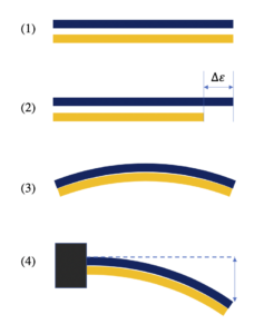
Bimetallic strip
Image – Bimetallic strips;
Image Credit – Wikimedia Commons

Types:

Bimetallic strips classified in two sections,

Spiral strip type:

Spiral strip type bimetallic strips is contains a structure of spiral like in it a pointer is added thus the pointer can measure the temperature. When the structure of the spring shaped is heated the metals shown their property of thermal expansion and the structure of the spring shaped is deform when temperature is fall. In this period the scale is recorded the amount of temperature. Normally by the help of spiral strip type bimetallic strips we can record the temperature of ambient.

Helical type:

Helical type bimetallic strips is contains a structure of helical like in it a pointer is added thus the pointer can measure the temperature. When the structure of the helical shaped is heated the metals shown their property of thermal expansion and the contracts on cooling. In this period the scale is recorded the amount of temperature. Normally by the help of helical strip type bimetallic strips we can record the temperature of industrial applications.

Advantages of Bimetallic strips:

  • Less cost
  • Robust
  • Simple in use
  • External power not needed
  • Give accuracy in between ± 2 to 5

Disadvantages of Bimetallic strips:

  • Low temperature does not work properly.
  • Measure up to 4000 centigrade

Application:

  • Bimetallic strip use in a fire detector or fire alarm
  • Bimetallic strip use in mechanical clocks for minimize the errors during the changes of temperature.
  • Heaters
  • Iron box
  • Heat engine
  • Thermistor
  • Fans

Riveting:-

Riveting is work on the basic of thermal expansion. Riveting is a fixed mechanical fastener. Rivets made with aluminium or steel and used to joining the metal pieces.  River joints contain gun, rivet pin and operation with rivet is known as riveting.
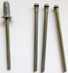
558px Blind rivet notches
Image – Rivet;
Image Credit – Wikimedia Commons

Types:

Types of rivet joints are,

  1. Button head rivet
  2. Join our Newsletter rivet
  3. Belt rivet
  4. Hollow rivet
  5. Boiler construction rivet Explosive rivet

Thermostats:-

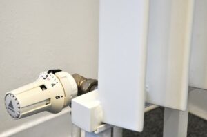
Thermostat is work on the basic of thermal expansion. Thermostat is a machine by which we can detect the amount of temperature changes. The thermostat uses in valves, switches, relays and many more.

Thermostat is a device which is works on two purposes one is for measurement and another one is for controlling function.
832e978152911fe543c3b66e0319bd853f8907fb
Image – Thermostat;
Image Credit – snappygoat.com

Cracks appearing in the roads:-

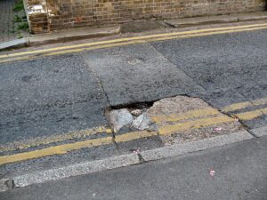
Cracks appearing in the roads it are another example of thermal expansion. Cracks in the road mainly happened in the hot afternoon when the temperature is rises too up. In the surrounding the temperature is rise up above the 90 degree and wrap and buckle is appearing.
Hampden Lane cracking. Update 27 April 2010
Image – Cracks appearing in the rod; Image Credit – Wikimedia Commons

Expansion joints:-

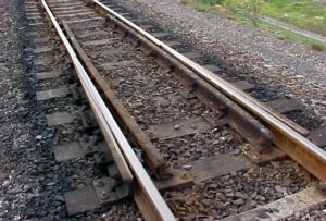
An expansion joint is an example of bellows type device. Expansion joints are mainly used for absorbing thermal expansion. In this way the expansion joints are make thus it could grip and holds the parts together when safely taking temperature induced expansion, vibration and also construction of a building material.

Expansion joints are used in railway tracks, sidewalks, buildings, ships, piping system, bridges.
Track Rail Expansion Joint
Image – Expansion joints,
Image Credit – Wikimedia Commons

Metal frame windows need rubber:-

Now in builds or other construction windows are made of metal. In these windows thermal expansion is happened for this particular reason rubber is use outside the frame of the window. Rubber is not good for heat conductor for this reason thermal expansion can be prevents and the frame will be stay at its correct position without any damage.

Tyre of the vehicle gets warm:-

When a vehicle is run for a long distance that time the tyre of the vehicles getting warm and thermal expansion is appear. Heat plays a vital role for getting warm of the vehicle tyres. When heat is increases the inside pressure is also increases for this reason the temperature is also goes up.

Frequent asked questions:-

Question: – Explain the coefficient of thermal expansion for matter.

Solution: – Thermal expansion coefficient is actually a physical condition of substance to change its area, shape, density and volume under changing of temperature. Thermal expansion is not including the phase transitions. The S.I unit of the thermal expansion is per Kelvin.

The equation for thermal expansion coefficient is,

gif

Where,

∝ = Coefficient of thermal expansion for gaseous matter

V = Volume for gaseous matter

T = Temperature for gaseous matter

P = Pressure for gaseous matter

For particularly 1 mole ideal gaseous substance PV = RT,

Where,

∝ = R/PV = 1/T

Types of thermal expansion coefficient:

The thermal expansion coefficient can be divided in three sections,

  • Linear expansion coefficient
  • Area expansion coefficient
  • Volume expansion coefficient

Linear expansion coefficient:-

Linear expansion coefficient can be explained as, changing of length due to temperature.

Linear expansion coefficient can be written as,

gif
gif

Where,

ΔL= Changing in length

L0= Original length

∝ = Length expansion coefficient

L = Expanded length

Δ T = Temperature difference

Area expansion coefficient:-

Area expansion coefficient can be explained as, changing of area due to temperature.

Area expansion coefficient can be written as,

gif
gif

Where,

ΔA= Changing in area

A0= Original area

∝= Area expansion coefficient

A = Expanded area

Δ T= Temperature difference

Volume expansion coefficient:-

Volume expansion coefficient can be explained as, changing of volume due to temperature.

Volume expansion coefficient can be written as,

gif
gif

Where,

Δ V = Changing in volume

V0 = Original volume

∝ = Volume expansion coefficient

V = Expanded volume

ΔT= Temperature difference

Question: –

Rup daily uses a rod or his gardening purpose, one day he forgets to bring the rod at his own house. The length of the rod is 10 meter at the temperature of 39 degree centigrade. After forget the rod the length of the rod became 15 meter and that time the temperature is 35 degree centigrade.

Now determine the thermal expansion coefficient for the rod.

Solution: – Given data are,

Changing in length ΔL = (15 – 10) meter = 5 meter

Original length L0 = 10 meter

 Length expansion coefficient ∝= ?

Expanded length L = 15 meter

Temperature difference Δ T = (39 – 35) degree centigrade = 4 degree centigrade

Absolute temperature = T = (273 + 4) K = 278 K

gif
gif
gif
gif

Rup daily uses a rod or his gardening purpose, one day he forgets to bring the rod at his own house. The length of the rod is 10 meter at the temperature of 39 degree centigrade. After forget the rod the length of the rod became 15 meter and that time the temperature is 35 degree centigrade.

The thermal expansion coefficient for the rod is 17 x 10 -4 K -1

ECL vs TTL: Speed Advantages Explored

ecl vs ttl speed advantages

ECL (Emitter Coupled Logic) and TTL (Transistor-Transistor Logic) are two of the most widely used digital logic families, each with its own unique characteristics and advantages. When it comes to speed, ECL has a clear edge over TTL, offering significantly faster propagation delays and higher switching speeds. In this comprehensive blog post, we’ll delve into … Read more

7 Real Gas Examples: Under Which Circumstance

371px Soda fountain in China 01 186x300 1

In this article “Real gas examples” and real gas examples related which circumstances will be summarized. Real gas examples are does not follow the law of gases. Real gas examples works in low temperature.

8+ Ideal Gas Examples are listed below,

Soda fountains (Carbon dioxide):-

The soda fountains is a machine device by which we can get carbonated soft drinks, this types of drinks called fountain drinks. The soda fountains devices are now available in everywhere almost from start to restaurants it easily available in local markets. In the soda fountains machines syrup concentrate or flavoured syrup is mix up with purified and chilled water, carbon dioxide.

With taking the help of soda gun the drinks can easily can out from the device.  Now bag in box soft drinks are kept in the soda fountains device. The carbon dioxide one of the most soluble gas substance among the all toxic gases thus carbon dioxide is the appropriate gas for preserve the drinks.

Real gas examples
Image – Soda fountains;
Image Credit – Wikimedia Commons

Cable TV and WiFi (Helium):-

In cable TV and WiFi connection real gas is use. In telecommunications, cable internet or cable internet access helium gas is use. Now a day uses of internet by help of cable lines gives lots of development and advancement of our busy schedule.

Wireless Screencasting
Image – Cable TV and WiFi;
Image Credit – Wikimedia Commons

Benefit of Cable TV and WiFi:

  • Reliable
  • Admirable service

Light bulbs (Argon):-

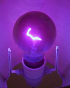
Inside the light bulbs argon gas is used. The light bulb mainly depends on the working principle of incandescence. The meaning the incandescence is the light bulbs make light when heat is produced.

When in a thin metal filament of light bulb electric current is flows that time the filament getting heat and after heated it start to glow and in this way light is produce. In the light bulb filaments are made of tungsten because this metal have higher melting point compare to other metal.

Ultraviolet light bulb 2
Image – Light bulbs;
Image Credit – Wikimedia Commons

Bakery products (Carbon dioxide):-

In bakery products carbon dioxide is used.  In bakery products such as pies, rolls, breads, muffins and pastries sodium bicarbonate is uses. When the sodium bicarbonate mixes up with the products of bakery that time carbon dioxide is produce.

800px Chinese bakery eastsection
Image – Bakery products;
Image Credit – Wikimedia Commons

Hot air balloon (Hydrogen and Helium):-

Hot air balloon is lighter than the air craft. The hot air balloons have a big size balloon which is named envelope which has heated air. Inside the hot air balloons hydrogen and helium gas are present. A basket is present in it.

800px Colorado Springs Hot Air Balloon Competition
Image – Hot Air Balloons;
Image Credit – Wikimedia Commons

Opening of a soda bottle (Carbon dioxide):-

In a soda bottle compressed carbon dioxide is uses. The main reason behind using the carbon dioxide inside the bottle is this is the most non toxic gas. The fizz that bubbles up when we crack open a can of soda is carbon dioxide gas CO2. The industrial who make the soft drinks add this tingling froth by forcing carbon dioxide and water into your soda at high pressures—up to 1,200 pounds per square inch.

Fire extinguisher (Carbon dioxide):-

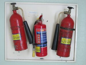
A fire extinguisher which is a device works as a safety device. Inside the fire extinguisher carbon dioxide is placed. It is used to control small size fire thus a big accident can be prevented.

800px Fire extinguishers in a hotel in Coxs Bazar
Image – Fire Extinguisher;
Image Credit – Wikimedia Commons

In general two types of fire extinguisher are available. They are,

  • Stored pressure fire extinguisher
  • Cartridge operated fire extinguisher

Paintball (Nitrogen and carbon dioxide):-

The paintball is a comparative and very fun game. The purpose of the game is to hit a target object with the help of paintball. The gelatine shells are used to make paintballs. Inside the paintball carbon dioxide and nitrogen is placed. Inside the paintball carbon dioxide and nitrogen took place as liquid but when the trigger is pulled that time carbon dioxide and nitrogen under high pressure change its state and became gas.

NAdo JTF3
Image – Paintball;
Image Credit – Wikipedia

Frequent asked questions:-

Question: – What are the properties for the real gas.

Solution: – Real gas isa gaseous matter which are work in higher pressure and lower temperature. In our surroundings real gas are present. Real gases not follow gas law at any particular temperature or pressure.

The properties for the real gas is given below,

  1. When the real gas is comes across the porous plug that time the real gas passes high pressure to the comparative low pressure, for this particular reason temperature is changes.
  2. Real gas substance can be liquidities. The reason behind of it the molecules of the real gas have a physical property that is intermolecular attraction by which molecules can coalesce.
  3. The thermal expansion coefficient is depending upon the character of the real gas molecules.
  4. The compressibility coefficient is depending upon the character of the real gas molecules.
  5. Intermolecular attraction is present in the real gaseous substance. When the real gaseous substance is expanding the particles of the real gaseous substance have more kinetic energy to defeated intermolecular attraction and the temperature is changed.
  6. When the temperature of the real gaseous substance is under the critical temperature that time the molecules of real gaseous substance can liquefied under particular temperature and pressure.

Question: – Explain the coefficient of thermal expansion for gas.

Solution: – Thermal expansion actually a physical condition of substance to change its area, shape, density and volume under changing of temperature. Thermal expansion is not including the phase transitions. The S.I unit of the thermal expansion is per Kelvin.

The equation for thermal expansion coefficient is,

gif

Where,

α = Coefficient of thermal expansion for gaseous matter

V = Volume for gaseous matter

T = Temperature for gaseous matter

P = Pressure for gaseous matter

For particularly 1 mole ideal gaseous substance PV = RT,

Where,

α = RP/V = 1/T

1280px Carnot heat engine 2.svg
Image – Thermal expansion;
Image Credit – Wikipedia

Types of thermal expansion:

The thermal expansion can be divided in three sections,

  • Linear expansion
  • Area expansion
  • Volume expansion

Linear expansion:-

Linear expansion can be explained as, changing of length due to temperature.

Linear expansion can be written as,

gif

Where,

ΔL = Changing in length

L0 = Original length

α= Length expansion coefficient

L = Expanded length

ΔT= Temperature difference

Area expansion:-

Area expansion can be explained as, changing of area due to temperature.

Area expansion can be written as,

gif

Where,

ΔA = Changing in area

A0 = Original area

α = Area expansion coefficient

A = Expanded area

ΔT= Temperature difference

Volume expansion:-

Volume expansion can be explained as, changing of volume due to temperature.

Volume expansion can be written as,

gif

Where,

ΔV = Changing in volume

V0 = Original volume

α = Volume expansion coefficient

V = Expanded volume

 Δ T= Temperature difference

Question: – Explain the coefficient of compressibility for gas.

Solution: – The coefficient of compressibility for gaseous matter is decreasing the amount of volume in per unit volume created by per unit change in pressure.

Read more about Thermal diffusivity : Its’s all important Facts and FAQs

Mathematically coefficient of compressibility written as,

gif

Where,

β = Coefficient of compressibility for gaseous matter

V = Volume for gaseous matter

P = Pressure for gaseous matter

T = Temperature for gaseous matter

Coefficient of compressibility (β) for ideal gases,

gif

Therefore, β should be a function of pressure only and the same for all gases. But experimentally the coefficient of compressibility has been found to be individual property

Question: – Explain the compressibility factor equation for gas.

Solution: – With the help of compressibility factor equation for gas we can understand reach of deviation of real gaseous substance from ideal gaseous substance character.

The compressibility factor equation for gas is,

Z = PV/RT

Where,

Z = Compressibility factor constant for gaseous substance

P = Pressure for gaseous substance

V = Volume for gaseous substance

R = Gas constant for gaseous substance

T = Temperature for gaseous substance

Read more about Pressure vessel design : It’s important facts and 5 parameters

Now, when the value of Compressibility factor constant for gaseous substance

Is equal to 1 (Z = 1) that time no deviation is present from the ideal gaseous substance behaviour.

Now, when the value of Compressibility factor constant for gaseous substance

Is not equal to 1 Z ≠ 1 that time the value of the unit for Z is measure for reach of non ideality.

When the value of Compressibility factor constant for gaseous substance

Is greater than 1 (Z < 1) that time the ideal gaseous substance will be more compressible.

When the value of Compressibility factor constant for gaseous substance

Is less than 1 (Z  > 1) that time the ideal gaseous substance will be not more compressible.

Read more about Specific Enthalpy : Its important properties & amp; 8 FAQ’s

Question: – The difference between real gas and ideal gas describe.

The major points are derive about the difference between real gas and ideal gas,

ParameterIdeal gasReal gas
DefinitionThe gas which are follow the law of gas at particular condition of constant pressure and temperatureThe gas which are not follow the law of gas at particular condition of constant pressure and temperature
FormulaThe formula which ideal gas is follow,
PV = nRT
Where,
P = Pressure
V = Volume
n = Amount of substance
R = Ideal gas constant
T = Temperature
The formula which real gas is follow,
V%5E2%29%28V%20 %20nb%29%7D%20%3D%20nRT
Where,
P = Pressure
a = Parameter which need to determine empirically for individual gas
V = Volume
b = Parameter which need to determine empirically for individual gas
n = Amount of substance
R = Ideal gas constant
T = Temperature  
AvailabilityNot existExist

3 Ideal Gas Examples: Under Which Circumstance:

Boyles Law animated

In this article “Ideal gas examples” and ideal gas examples related facts will be discuss. Ideal gas examples are based on law of ideal gas. But in practical life ideal gas is not present in the universe.

3+ Ideal Gas Examples are listed below,

Example 1:-

Calculate the amount of density for the Nitrogen gas at the pressure of 256 Torr and 25 degree centigrade temperature.

Solution: – Given data are,

P = 256 Torr = 256 Torr x 1 atm/760 Torr = 0.3368 atm

V =?

T = (25 + 273) K = 298 K

n =?

Now we apply the formula for ideal gas,

PV = nRT   ………. eqn (1)

So, we also can write the density is,

ρ = m/v ………. eqn (2)

Where,

ρ = Density of the ideal gas

m = Mass of the ideal gas

v = Volume of the ideal gas

Now, m = M x n ………. eqn (3)

Where,

m = Mass

M = Molar mass

n = Moles

From eqn (2) and eqn (3) we get,

ρ = m/v …… (4)

Arranging the eqn (2) and eqn (3) we get,

ρ = M x n/V ……eqn(5)

ρ/M = n/V……eqn(6)

Now applying the equation of ideal gas,

PV = nRT

n/V =ρ /M ……eqn(7)

n/V = P/RT ……eqn(8)

From eqn (6) and eqn (8) we get,

ρ/M} = P/RT ……eqn(9)

Isolate density,

ρ = PM/RT……eqn(10)

ρ = (0.3368 atm)(2 x 14.01gram/mol)/(0.08206 L*atm*mol-1*K-1 )(298 K)

ρ = 0.3859 gram / mol

The amount of density for the Nitrogen gas at the pressure of 256 Torr and 25 degree centigrade temperature is 0.3859 gram / mol.

Ideal gas examples
Image – Nitrogen : Example of ideal gas;
Image Credit – Wikimedia Commons

Example 2:-

A container which is filled with the Neon gas. The amount Neon in container is 5.00 Litre that time the temperature is 26 degree Centigrade at 750 mm Hg. A carbon dioxide vapour is now added to the container. The quantity of carbon dioxide added to the container is 0.627 gram.

Now determine these factors,

Partial pressure for Neon in atm.

Partial pressure for carbon dioxide in atm.

Total pressure present in the container.

Solution: – Given data are,

P = 750 mm Hg -> 1.01 atm

V = 5.00 Litre

T = (26 + 273) K= 299 K

nne =?

nco2 =?

For Carbon dioxide the number of mole is,

nco2 = 0.627 gram CO2 = 1 mol/44 gram = 0.01425 mol CO2

Now for Neon the number of mole is,

gif

nNe= 0.206 mol Ne

Before adding the carbon dioxide to the container we can get only pressure for neon. So the partial pressure for neon is definitely the amount of pressure is already discussed in question.

Now for the carbon dioxide,

Using the equation of ideal gas equation we can write,

gif

For the both Carbon dioxide and Neon Temperature, volume and gas constant remain same.

So,

gif

1.01 atm/0.206 mol Ne = PCO2/0.01425 mol CO2

PCO2 = 0.698 atm

Total pressure,

Ptotal = PNe + PCO2

Ptotal= 1.01 atm + 0.698 atm

Ptotal = 1.708 atm

Partial pressure for Neon is 1.01 atm.

Partial pressure for carbon dioxide 0.698 atm.

Total pressure present in the container is 1.708 atm.

Example 3:-

Determine the amount of volume.

In a glass container carbon dioxide gas is present. The temperature of the carbon dioxide gas is 29 degree centigrade, pressure is 0.85 atm and the mass of the carbon dioxide gas is 29 gram.

Solution: – Given data are,

P = 0.85 atm

m = 29 gram

T = (273 + 29) K = 302 K

The mathematical form of the ideal gas is,

PV = nRT ……..eqn (1)

Where,

P = Pressure for the ideal gas

V = Volume for the ideal gas

n = Molar number for the ideal gas

R = Universal gas constant for the ideal gas

T = Temperature for the ideal gas

If in a matter M denoted as molar mass and mass of a matter denoted as m then the total number of moles for that particular matter can be expressed s,

n = m/M ……..eqn (2)

Combine the ……..eqn (1) and ……..eqn (2) we get,

PV = mRT/M ……..eqn (3)

We know the value of molar mass for carbon dioxide is,

M = 44.01 gram/ mol

From eqn (3) we can write,

V = mRT/M = 29 gram x 0.0820574 L*atm*mol-1*K-1 x 302/44.01 gram/mol x 0.85 atm

V = 19.21 Litre

In a glass container carbon dioxide gas is present. The temperature of the carbon dioxide gas is 29 degree centigrade, pressure is 0.85 atm and the mass of the carbon dioxide gas is 29 gram. Then the amount of volume is 19.21 Litre.

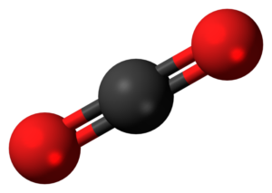
Carbon dioxide 3D ball
Image – Carbon dioxide;
Image Credit – Wikipedia

Real gas vs. Ideal gas:

Ideal gases follow the law of gas in a particular constant condition but real gas does not follow the law of gas in a particular constant condition. In practical life ideal gas is not exist but real gas is exist.

The major points are derive about the difference between real gas and ideal gas,

ParameterIdeal gasReal gas
DefinitionThe gas which are follow the law of gas at particular condition of constant pressure and temperatureThe gas which are not follow the law of gas at particular condition of constant pressure and temperature
Movement of particlesThe particle present in the ideal gas is free to move and the particle does not attend in interparticle interaction.The particle present in the real gas is not free to move and compete with each other, the particle attend in interparticle interaction.
Volume occupiedNegligibleNot negligible
PressureHigh pressure is presentLower pressure than the ideal gas pressure
Force presentIntermolecular force of attraction is not presentIntermolecular force of attraction is present
FormulaThe formula which ideal gas is follow,
PV = nRT
Where,
P = Pressure
V = Volume
n = Amount of substance R = Ideal gas constant
T = Temperature
The formula which real gas is follow,
(P + an2/V2)(V – nb) = nRT
Where,
P = Pressure
a = Parameter which need to determine empirically for individual gas
V = Volume
b = Parameter which need to determine empirically for individual gas
n = Amount of substance
R = Ideal gas constant
T = Temperature  
AvailabilityNot existExist

Read more about Isothermal process : Its’s all Important facts with 13 FAQs

Frequent asked questions:-

Question: – Derive the limitations of ideal gas.

Solution: – The limitations of ideal gas is listed below,

  • Ideal gas could not work in high density, low temperature and high pressure
  • Ideal gas not applicable for heavy gases
  • Ideal gas not applicable strong intermolecular forces.
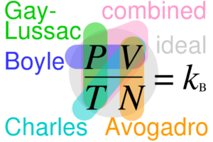
Ideal gas law relationships.svg
Image – Ideal gas;
Image Credit – Wikipedia

Read more about Gauge Pressure : It’s Important Properties with 30 FAQs

Question: – Write down the assumptions about the ideal gas.

Solution: – Actually in our surrounding ideal gas is no present. The law of ideal gas is a simple equation by which we can understand the relation between pressures, volume and temperature for gases.

The assumptions about the ideal gas is listed below,

  • The gas particles of ideal gas have negligible volume.
  • The size of the gas particles of ideal gas is equal and they don’t have intermolecular force.
  • The gas particles of ideal gas have follows the law of motion of Newton’s.
  • There is no loss of energy.
  • The gas particles of ideal gas have elastic collision.

Question: – Derive the different form equation for ideal gas.

Solution: – Ideal gas formula actually combination of Boyle’s law, Avogadro’s law, Charle’s law and Gay Lussac’s law.

The different form equation for ideal gas is briefly summarize below,

Common form of ideal gas:

PV = nRT = nkbNAT = NkBT

Where,

P = Pressure for the ideal gas measured in Pascal

V = Volume for the ideal gas measured in cubic meter

 n = The total of ideal gas which is measured in moles measured in mole

R = Gas constant for the ideal gas which value is 8.314 J/K.mol = 0.0820574 L*atm*mol-1*K-1

T = Temperature for the ideal gas measured in Kelvin

N = The total number of the ideal gas molecules

kb = Boltzmann constant for the ideal gas

NA = Avogadro constant

Molar form of ideal gas:

Pv = Rspecific T

P = Pressure for the ideal gas

v = Specific volume for the ideal gas

Rspecific = Specific gas constant for the ideal gas

T = Temperature for the ideal gas

Statistical form of ideal gas:

P = kb/μ mμρ T

Where,

P = Pressure for the ideal gas

kb = Boltzmann constant for the ideal gas

μ= Average partial mass for the ideal gas

mμ = Atomic mass constant for the ideal gas

ρ = Density for the ideal gas

T = Temperature for the ideal gas

Combined gas law:-

PV/T = k

P = Pressure

V = Volume

T = Temperature

k = Constant

When same matter in present two different condition that time we can write,

P1V1/T1 = P2V2/T2

Question: –Derive the law of Boyle.

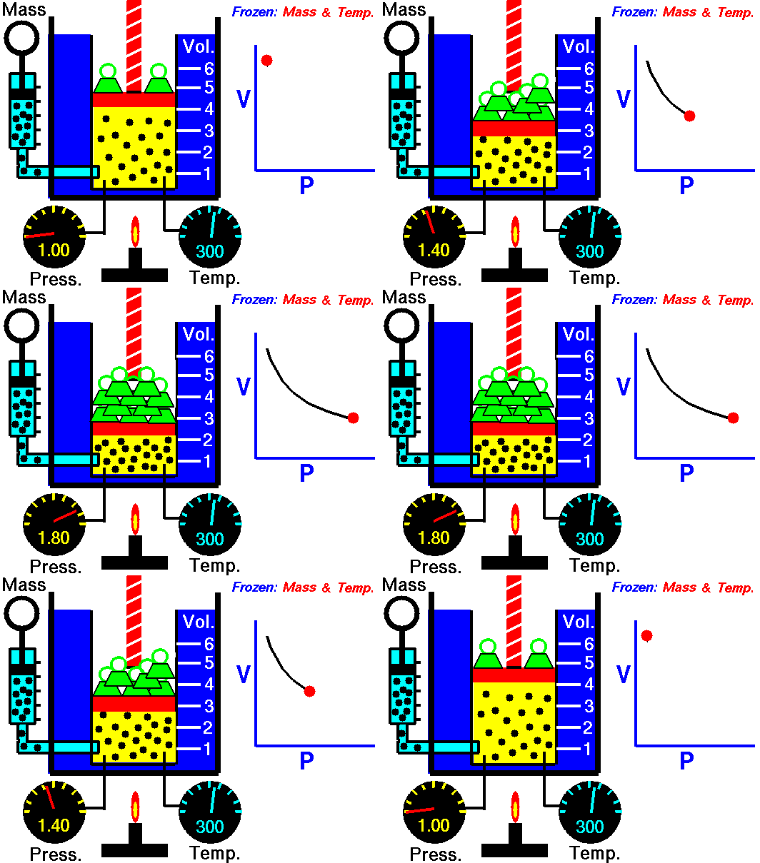
Solution: – Boyle’s law is a gas law. The gas law of Boyle’s derive that the pressure exerted by a gaseous substance(of a given mass, kept at a constant temperature) is inversely proportional to the volume occupied by it.

Boyles Law animated
Image – Boyle’s law;
Image Credit – Wikimedia

In other words, the pressure and volume of a gas are indirectly proportional to each other to the temperature and the quantity of gas are kept constant. 

The gas law of Boyle’s can be expressed mathematically as follows:

P1V1 = P2V2

Where,

P1 = The initial pressure exerted by the gaseous substance

V1 = The initial volume occupied by the gaseous substance

P2 = The final pressure exerted by the gaseous substance

V2 = The final volume occupied by the gaseous substance

This expression can be obtained from the pressure-volume relationship suggested by Boyle’s law. For a fixed amount of gas kept at a constant temperature, PV = k. Therefore,

P1V1= k (initial pressure x initial volume)

P2V2 = k (final pressure x final volume)

∴ P1V1 = P2V2

As per Boyle’s law, any change in the volume occupied by a gas (at constant quantity and temperature) will result in a change in the pressure exerted by it.

Mastering NAND Gate Symbols: A Comprehensive Guide for Electronics Students

nand gate symbols

NAND gates are fundamental building blocks in digital electronics, widely used in various electronic circuits and systems. This comprehensive guide delves into the technical specifications and symbolic representations of NAND gates, providing electronics students with a deep understanding of this essential logic gate. Gate-level and Transistor-level Representation of NAND2_X1 The NAND logic function provides a … Read more

What is an Amplifier: A Beginner’s Guide to Understanding Audio Amplification

what is an amplifier a beginners guide to understanding audio amplification

An amplifier is a crucial component in any audio system, responsible for boosting the strength of an electrical signal to a level that can effectively drive speakers and produce sound. This process not only increases the volume but also preserves the quality and fidelity of the original audio signal across various frequencies. Understanding the role … Read more

Mastering Transformer Tap Voltage: A Comprehensive Guide for Electronics Students

transformer tap voltage

Transformer tap voltage is a critical parameter that determines the voltage level at different tap positions of a transformer. Understanding and managing transformer tap voltage is essential for electronics students to ensure the proper operation and maintenance of transformers in various applications. This comprehensive guide will delve into the technical details and provide a hands-on approach to mastering transformer tap voltage.

Understanding Transformer Tap Voltage

Transformer tap voltage refers to the voltage level at different tap positions of a transformer. The voltage level can be adjusted by changing the taps, which in turn changes the turns ratio of the transformer. The transformer tap voltage can be calculated using the formula for the turns ratio:

Vsecondary/Vprimary = Nsecondary/Nprimary

where Vsecondary is the secondary voltage, Vprimary is the primary voltage, Nsecondary is the number of turns in the secondary winding, and Nprimary is the number of turns in the primary winding.

To increase the secondary voltage, the turns ratio must be decreased, which can be achieved by selecting a tap with fewer turns on the primary winding. Conversely, to decrease the secondary voltage, the turns ratio must be increased, which can be achieved by selecting a tap with more turns on the primary winding.

Tap Configurations and Voltage Adjustment

Transformers can have various tap configurations to accommodate different voltage requirements. The most common tap configurations are:

  1. 5-Position Tap Configuration: This configuration has two taps above and two taps below the nominal rating, allowing for instances where the supply is either higher or lower than the transformer’s nominal rating.

  2. 7-Position Tap Configuration: This configuration includes two taps above and four taps below the nominal rating, allowing for a supply voltage which is within 5% above and 10% below the nominal voltage rating.

The voltage level at each tap position can be calculated using the turns ratio formula. For example, a transformer with a nominal rating of 480V and a 5-position tap configuration may have the following tap voltages:

Tap Position Voltage Level
+5% 504V
+2.5% 492V
Nominal 480V
-2.5% 468V
-5% 456V

It’s important to note that the actual voltage levels may vary slightly due to factors such as load, temperature, and transformer design.

Measuring Transformer Tap Voltage

The transformer tap voltage can be measured using two main methods:

  1. Voltage Transformer: A voltage transformer is connected to the transformer terminals and measures the voltage level at each tap position. This method provides a direct and accurate measurement of the tap voltage.

  2. Multimeter: A multimeter can also be used to measure the voltage level at each tap position by connecting the multimeter leads to the transformer terminals. This method is less accurate than using a voltage transformer but can still provide a reliable measurement.

When measuring the transformer tap voltage, it’s essential to ensure that the transformer is under load to obtain accurate readings. The voltage level may vary depending on the load conditions, so it’s recommended to measure the tap voltage under the expected operating conditions.

Calculating Transformer Tap Voltage

In addition to direct measurement, the transformer tap voltage can also be calculated using a transformer tap changer calculator. These calculators are available online and can be a valuable tool for electronics students.

The calculator takes the measured primary voltage and calculates the secondary voltage for each tap position. This allows the user to determine the appropriate tap position to obtain the desired nominal voltage. The calculator can also provide information on the turns ratio and other transformer parameters.

Transformer Winding Resistance Measurement

transformer tap voltage

In addition to the voltage level, the resistance of the transformer windings can also be measured to detect any winding damages or contact problems. The winding resistance is measured in all tap positions in all three windings, and a static resistance graph is created from the measured values.

The winding resistance is measured in ohms and can vary depending on the size and type of transformer. The resistance graph can be analyzed to detect any changes in the winding material temperature, high-resistance contacts, or specific graph shapes that indicate contact problems.

By measuring the winding resistance, electronics students can identify potential issues with the transformer and take appropriate actions to ensure its proper operation and maintenance.

Advanced Transformer Tap Voltage Considerations

Beyond the basic understanding of transformer tap voltage, there are several advanced considerations that electronics students should be aware of:

  1. Tap Changer Mechanisms: Transformers can be equipped with different types of tap changers, such as on-load tap changers and off-load tap changers. Each type has its own unique characteristics and operational requirements.

  2. Tap Changer Maintenance: Regular maintenance of the tap changer is crucial to ensure its proper functioning and prevent issues such as contact wear, insulation deterioration, and mechanical failures.

  3. Voltage Regulation: Transformer tap voltage can be used to regulate the voltage in electrical systems, particularly in applications with varying load conditions or voltage fluctuations.

  4. Harmonics and Power Quality: The transformer tap voltage can also impact the power quality of the electrical system, as changes in the turns ratio can affect the harmonic content and voltage waveform.

  5. Transformer Efficiency: The transformer tap voltage can influence the overall efficiency of the transformer, as the turns ratio affects the transformer’s losses and performance.

By understanding these advanced considerations, electronics students can develop a comprehensive knowledge of transformer tap voltage and its impact on the overall performance and operation of transformers.

Conclusion

Transformer tap voltage is a critical parameter that electronics students must master to ensure the proper operation and maintenance of transformers. This comprehensive guide has provided a detailed overview of the technical aspects of transformer tap voltage, including the calculation, measurement, and advanced considerations.

By understanding the concepts and techniques presented in this guide, electronics students can confidently work with transformers, troubleshoot voltage-related issues, and optimize the performance of electrical systems. Mastering transformer tap voltage is a valuable skill that will serve electronics students well in their future careers.

References

  1. Transformer Tap Changer Calculator – Voltage Disturbance On-Load Tap Changer Testing Methods | DV Power
  2. On-Load Tap Changer – an overview | ScienceDirect Topics
  3. Transformer tap changers & voltage adjustment taps – Transformer Tap Changer: How to Select Transformer Taps?

Aerobic Septic System Diagram: Detailed Explanations:

800px Greywater septic tank outlet 3255728552 300x225 1

In this article “Aerobic septic system diagram” and aerobic septic system diagram related others facts will be discuss. Aerobic septic system diagram actually use components which are related to mechanical.

The aerobic septic system diagram is another form name is aerobic treatment system. In aerobic septic system a very small size sewage treatment system is work. It is almost same as septic tank system. In aerobic septic system mainly mechanical materials are used to treat discharge or sewage to an absorption area.

Read more about How Does A Heat Pump Work In Winter : Complete Insights, Critical FAQs

Septic pump system diagram:

Septic pump is systems contain a chamber which is placed in underground. It is made with fibreglass, concrete, plastic. In the chamber of septic pump system domestic sewage can flow for treatment.

Septic pump system diagram is given below,

Aerobic septic system diagram
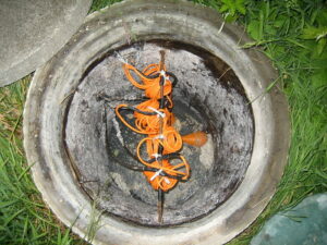
Image – Aerobic septic system; Image Credit – Wikimedia Commons
Schematic of a septic tank 2
Image – Septic tank system;
Image Credit – Wikipedia

Aerobic vs. anaerobic septic system:

The major difference aerobic vs. anaerobic septic system is discuss below,

ParameterAerobic septic systemAnaerobic septic system
By productAerobic septic system produce 1.Water
2. Excess amount of biomass
3. Carbon dioxide
Anaerobic septic system produce,
1. Excess amount of biomass
2. Carbon dioxide
3. Methane
Capital costNot too highHigh
Maintenance costExpensiveNot too much expensive
Typical technologies1. Moving bed bioreactor
2. Activated sludge
3. Extended aeration
4. Tricking filters
5. DHS(Down flow hanging sponge)
6. Oxidation ditch
7. MBR(Membrane bioreactor )
1. Hybrid high rate reactor
2. Single stage UASB reactor
3. Two stage UASB reactor
4. Continuously stirred tank reactor
5. Continuously stirred tank up flow
6. Continuously stirred tank digester  
EnergyHigh energy needed.Low energy needed.
Volume of sludgeLargeLow
Hydraulic retention timeHighLow
Operation  EasyNot easy  
Structure  SimpleComplex
ProcessIn the
aerobic septic system bacteria continuously supplied into the tank where oxygen is also present. The continuous flow of oxygen helps to keep the bacteria more effective and the treatment process can flow continuously. A movable pallet is placed in the tank thus wastewater can avoid splitting into different three layers. This process is easier to treatment wastewater.
In the system tank of the anaerobic two components are placed, one is treatment tank and another is seepage field. At first wastewater is delivering to the treatment tank. In the Treatment tank solid type waste is store in the bottom of the portion. In the top portion slag is placed and in the center of the tank waste water is placed. The wastewater is clean for this reason the water can flow by the pipes which are hidden placed into the leach area. Divider box is situated in the pipes.  From the tank the wastewater flows more fluently. Before the step of filtration treated wastewater is back to the surrounding takes place at the point of leaching.
Effectiveness MoreLess

Frequent asked question:-

Question: – Write the positive sides of Aerobic septic system diagram.

Solution: – The positive sides of Aerobic septic system diagram is listed below,

  1. Aerobic septic system reduce nitrogen
  2. Helps to decreasing drain field clogging
  3. Aerobic septic system perfect for water conservation
  4. Long life is high
  5. Continuously produce high quality wastewater
  6. Aerobic septic system produces clean effluent
  7. Aerobic septic system takes very less amount space for installation
  8. Aerobic septic system can establish in various types of soils
  9. Environmental friendly
  10. Maintenance is very low
  11. Simple design

Question: – Write the negative sides of Aerobic septic system diagram.

Solution: – The negative sides of Aerobic septic system diagram is listed below,

  1. The noise of the blower is too much excessive
  2. Installation cost is high
  3. More power draws
  4. Bad odour can comes if vented is not done properly
  5. Excessive amount of water is use in the Aerobic septic system
  6. Sometimes ammonia is emitted which could causes pollution in the nature.
  7. Aerobic septic system should be insulated neither in winter unfavorable condition will be appear
  8. High amount electricity is essential
  9. Frequent pumping needed
  10. Need more inspection

Question: – Describe the classifications of septic tank system.

Solution: – The size, shape, design can widely changes due to classified the septic tank system. The size factor of septic tank system included soil type, lot size, water bodies, weather condition and many more.

The classifications of septic tank system is listed below,

Mound system:-

The most common classifications of septic tank system are Mound system. In the mound system tank is commonly used in high groundwater, soil depth and shallow bedrock. The mound system tank is made with sand and contained a drain field trench.

Wastewater is flow from septic tank to pump chamber. In the tank wastewater is pumped to the mound system that it could prescribed doses. After treatment of wastewater the water is discharge from the trench. After discharging the water is filter by sand and finally into the soil the water is disperses.

The mound septic tank system need periodic maintenance and a large amount space to install.

Septic tank:

The septic tank contained two chamber and these chambers are made of brick or concrete. PVC, pre or fibreglass septic tank, fabricated concrete rings is also available that will be less expensive.

The septic tank is small size scale decentralised treatment. The septic tank is actually a sedimentation tank and it is available in cylindrical or rectangular shape.

Advantages of septic tank:

  • Electrical energy is not essential
  • Little space required
  • Low operating cost
  • Long service life
  • Simple construction

Disadvantages of septic tank:

  • Only appropriate for low density housing
  • Low reduction in solids, pathogens and organics
  • Manual cleaning

Chamber system:

The chamber system type septic tank has series of chamber which are connected to each other. The chamber system septic tank area and its surrounding is filled with soil.

The chamber system septic tank has many types such as fabric wrapped pipe, open bottom chamber and many more.

Aerobic treatment unit:

Aerobic treatment unit is a natural process by which wastewater is treated. Oxygen rich bacterial is work for treatment in wastewater. For this process not too much space is needed and easy to construct.

Aerobic treatment unit process is done in four stages,

  • Pre treatment
  • Aeration chamber
  • Disinfection
  • Final treatment disposal

Conventional system:

In the conventional septic tank system which is used for very small size household or small business. The conventional septic tanks contain a septic tank and a bed subsurface or trench subsurface wastewater drain field system.

Drip distribution system:

Drip distribution septic tank system is used in many verities of drain fields. In the drip distribution septic tank system very large amount mound of soil is not needed.

This type of system maintenance cost is too high and electrical energy is needed.

Constructed wetland system:

The constructed wetland system treatment process is appearing in natural wetlands. This type of system can work in the pressure distribution or gravity flow.

Recirculating sand filter system:

Recirculating sand filter system is systems that can be construct both in below or above the ground. This type of system is very expensive to maintain and to install. Recirculating sand filter system is very high level treatment process system.

Evapotranspiration system:

Unique drain field type is evapotranspiration system. It is only useful for the specific environmental condition. The weather must be adequate sunlight and heat and must be arid.

Community/Cluster system:

Community/Cluster system the wastewater is collect from two or more than two buildings. This type of system mainly present in rural areas. Its contraction is not too much complicated.

Mastering Edge Triggering in Flip Flops: A Comprehensive Guide

how does edge triggering in flip flops operate explained in detail

Edge triggering in flip flops is a fundamental concept in digital electronics, and understanding its operation is crucial for designing reliable and efficient digital circuits. This comprehensive guide will delve into the intricacies of edge triggering, providing you with a deep understanding of how it works and the key parameters that govern its behavior. Understanding … Read more

Pressure Drag: What, How, Working, Formula, Examples:

pressure drag 300x116 1

In this article very interring topic “Pressure drag” is discusses. The cause of the pressure drag is pressure comparison intermediate surface of a matter. Pressure drag related everything is prate here.

Pressure drag derive as, when the molecules of the air being more pushed to each other on the surface of the matter’s front face and space is out more than the usual to the back face of the surface matter. The condition for a matter pressure drag more happened in the air particles for the flow of the turbulent.

What is pressure drag?

The relation between the velocity and pressure drag is directly proportional to each other. For the lower amount of velocity the amount of pressure drag is low and for the higher velocity pressure drag is high.

In a matter when force is acting that time the motion of the matter can stand against that known as pressure drag. When the matter is actually a gaseous matter is known as Air resistance or Aerodynamic drag and as the same time when the matter is actually a liquid matter is known as Hydrodynamic drag.

Read more about Gauge pressure : Its Important Properties with 30 FAQs

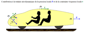
Pressure drag
Image – Pressure drag;
Image Credit – Wikimedia Commons

What is air pressure drag?

The main reason of the air pressure drag is size and shape of a matter. In the air pressure drag the layers of the air in not stays one directional due to the force for this reason turbulent flow is appear.

The meaning of the air pressure drag is the particles which are present in the air shoving more in the face of the substance and a huge placed diversion is produce in the back of the substance. Mainly the air pressure drags reason of the division of the border placer from a certain surface.

Read more about Pressure vessel design : It’s important facts and 5 parameters

How does pressure drag work?

Pressure drag work when the molecules present in the air more compressed on the face of the front plane and not more compressed on the face of the back plane for this reason the layers present in the air molecules being separate to each other and start to swirl, this condition known as turbulent flow.

Read more about Reynolds number : It’s 10+ Important facts

How to calculate pressure drag?

The equation of pressure drag state that, pressure drag which denoted as D is equal to the coefficient of drag which denoted as Cd multiplied the fluid density which denoted as r multiplied half of fluid velocity which denoted as V is square multiplied the area of reference which denoted as A.

Pressure drag can be calculate using this formula,

Pressure drag = Pressure drag coefficient x (Density x Velocity squred)/(2 x Reference area)

Mathematically can written,

D = Cd (ρ x v2) / (2 x A)

Where,

D = Pressure drag

Cd= Pressure drag coefficient

ρ = Density

 v = Velocity

 A = Reference area

Read more about Pressure vessel : It’s important facts and 10+ applications

How to reduce pressure drag?

The zone of the pressure low is appear behind the head, arms, back, and legs of the cyclists. It is very hard to reshape the parts from where the flow of the air is pass for reduce pressure drag.

The pressure drag can reduce in some ways, they are listed below,

  • Apply aero helmet
  • Body should be keep as low as possible
  • Hiding some equipment
  • The body should be keep in align
  • Head should be keep down
  • Double cap
  • Keep the kick tight
  • Point toes
  • Low profile goggles should be wearing
  • Hair should be shaving

How does air pressure affect drag?

The relationship with air pressure and drag is proportional to each other. Means the air pressure is increases then the drag amount is also increases and the air pressure is decreases then the drag amount is also decreases.

Pressure drag coefficient:

For any object which is moves in a motion due to force is applied that time drag is produce.

Pressure drag coefficient is the quantities resistance or drag of a particular matter in an environment which is based on liquid substance when force is exerted. The amount of the net force is act in the direction of the liquid substance flow due to shear stress and pressure on the plane of the particular matter.

Pressure drag coefficient
Image – Drag coefficient;
Image credit – Wikipedia

Read more about Compressive Stress and it’s overview with important facts

Pressures drag coefficient formula:

The formula of the coefficient of pressure drag is given below,

Fd = cd 1/2 ρ v2A

or, cd = 2Fd/ρ u2A}

Where,

Fd= Drag force express in Newton

cd = Drag coefficient

ρ= Density of a liquid substance express in kilogram per cubic meter

 v = Flow velocity of a liquid substance express in meter per second

A =Reference area for a particular body shape substance expressed in square meter The pressure drag coefficient depend upon some several facts of the parameters such as size and shape of any matter’s body, Flow of the liquid matter which is depend on Reynolds number, Mach number, Froude number and unevenness of the body.

How to calculate drag pressure coefficient?

Drag pressure coefficient can calculated using this formula,

gif

In eqn (2),

gif.latex?c p%20%3D%20%5Cfrac%7B2%7D%7B%5Crho%20v%5E2A%7D%5Cint %7BS%7D%5E%7B%7DdS%20%28p%20 %20p o%29%28%5Chat%7Bn%7D
gif

Where,

cd= Drag pressure coefficient

Fd = Drag force

A = Plan form area for a particular matter body

S = Wet surface for a particular matter body

cp = Pressure drag coefficient

cf = Friction drag coefficient

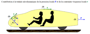
n̂= Perpendicular direction of a matter body which surface is dS. This is denoted the point from the fluid state to solid state

= Denoted the direction where shear stress is exerted on the matter of a body surface dS

î = Denoted the direction where vector is exerted in the flow of the stream

p = Pressure acted on the body of the matter at the dS surface

po = Far away pressure from the matter at the dS surface

Tw= Magnitude of the shear stress acted on the body of the matter at the dS surface

ρ = Density

v = Viscosity

Pressure drag vs. friction drag:

The compression between pressure drag and friction drag describe below,

ParameterFriction drag  Pressure drag
DefinitionWhen an object is flow in a liquid substance that time friction is appear between the liquid substance surface and the body of the matter and drag is produce. This type of drag is known as friction drag.Pressure drag is produce when the materials of a matter is resolved the force because of pressure is applied normally to the all points of the surface of a matter’s body.
Formulagif Where,
Cf = Skin friction coefficient
Tw = Skin shear stress which is applied in the surface plane of the body
v= Free stream speed for velocity of the body
ρ = Free stream speed for density of the body
1/2ρ v2 ≡ q = Free stream dynamic pressure for the body of the matter
gif or,
gif Where,
Fd = Drag force express in Newton
cd = Drag coefficient
ρ = Density of a liquid substance express in kilogram per cubic meter
v = Flow velocity of a liquid substance express in meter per second
A =Reference area for a particular body shape substance expressed in square meter  
DependentFriction between the surface and the body of the matterSize of the body
Pressure Drag and Friction Drag
Image – Pressure drag and Friction drag;
Image Credit – Wikimedia Commons

Pressure drag vs. skin friction drag:

The compression between pressure drag and skin friction drag describe below,

ParameterSkin friction drag  Pressure drag
DefinitionThe skin friction drag actually is an example of the state of aerodynamic drag. The skin friction drag can prevent force applied of a particular matter which is flowing in a motion in liquid substances.Pressure drag is mainly causes because of increasing pressure in front of a particular object and decreasing pressure in the back portion of the object.
Equationgif Where,
Cf= Skin friction coefficient
Tw= Shear stress for the local wall
q = Dynamic pressure for the free stream
gif
Now layers of boundary where pressure gradient is not applied in the direction of x that time momentum thickness can be express as,
gif
For the particularly turbulent flow the skin friction coefficient can be estimate using following equation,

For the particularly laminar flow the skin friction coefficient can be estimate using following equation,
gif
or,
gif
Where,
Fd = Drag force express in Newton
cd = Drag coefficient
ρ = Density of a liquid substance express in kilogram per cubic meter
v = Flow velocity of a liquid substance express in meter per second
A =Reference area for a particular body shape substance expressed in square meter  
DependentViscosityShape and size of the matter
RelationshipDirectly proportional to the viscosityDirectly proportional to shape and size of the matter
ExampleMotion of a airplane in air Motion of a matter in liquid substanceAir resistance Riding of a bicyclist Motion of a boat in water
800px Form drag and skin friction ratio.svg
Image – Skin friction drag;
Image Credit – Wikimedia commons

Read more about Shear modulus : Modulus of rigidity : It’s important facts and 10+ FAQ’s

Pressure drag vs. induced drag:

The compression between pressure drag and induced drag describe below,

ParameterPressure dragInduced drag
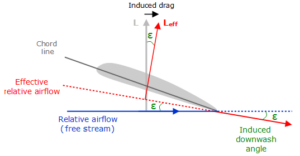
DefinitionWhen air molecules are compressed pressure drag produce.The position of the wing drag initiated by or working from the nature of the lift.
Relationship with speedThe relation between airspeed and pressure drag is directly proportional to each other.  The relation between airspeed and induced drag is indirectly proportional each other.  
Factor depend  1. Size and shape of the body of a object
2. Surrounding pressure
3.Motion of the liquid  
1. Size and shape of the body of a object
2. Inclination of a object
3. In the air flow condition of a object  
Induce drag downwash
Image – Induced drag;
Image Credit – Wikipedia

Pressure drag example:

Examples of the pressure drag is listed below,

  1. Airfoil
  2. Hummer H2 SUV
  3. Skydiver
  4. Bicycle
  5. Sphere
  6. Circular flat plate
  7. Honda civic
  8. Dodge ram pickup
  9. Toyota Camry
  10. Object moving in a liquid substance
  11. Speedboat

Read more about Drag Coefficient of Sphere.