The Direction of Torque: A Comprehensive Guide for Physics Students

direction of torque

Torque is a fundamental concept in physics, describing the rotational force that can cause an object to spin around an axis. Understanding the direction of torque is crucial for solving problems in rotational dynamics and kinematics. This comprehensive guide will delve into the technical details and provide a hands-on approach to mastering the direction of torque.

Understanding Torque as a Vector Quantity

Torque is a vector quantity, meaning it has both a magnitude and a direction. The direction of the torque vector is determined by the right-hand grip rule. Imagine curling your fingers around the axis of rotation, with your fingers pointing in the direction of the force. Your thumb will then point in the direction of the torque vector.

The torque vector defines the axis of motion that the object tends to rotate around. This is crucial in understanding the behavior of rotating systems, as the direction of the torque vector determines the direction of the rotational motion.

Describing the Plane of Rotation
direction of torque

The direction of the torque vector also provides information about the plane in which the object is rotating or could potentially rotate. One way to describe this plane is using the point normal form, where a vector perpendicular to the plane represents the torque vector.

This perpendicular vector, known as the normal vector, is essential in understanding the orientation of the rotational motion. It allows us to visualize the plane of rotation and the direction of the torque vector within that plane.

The Right-Hand Rule Convention

The use of the right-hand rule to determine the direction of the torque vector is a convention in physics. This convention is followed consistently, as it allows us to utilize the framework of vector mechanics in problems involving angular momentum and other rotational quantities.

The right-hand rule states that if you curl your fingers around the axis of rotation, with your fingers pointing in the direction of the force, your thumb will point in the direction of the torque vector. This convention is essential in maintaining consistency and simplifying the analysis of rotational systems.

Measuring Torque in Static and Rotating Systems

Measuring torque in a non-rotating, or static, system is relatively straightforward. By measuring the force and the length of the moment arm, the torque can be calculated directly using the formula: τ = r × F, where τ is the torque, r is the moment arm, and F is the force.

However, measuring torque in a rotating system is more challenging. One method involves measuring the strain within the metal of a drive shaft that is transmitting the torque and sending this information wirelessly. This allows for the indirect measurement of the torque in a rotating system.

Torque in Rotational Kinematics

The direction of the torque vector is a crucial concept in rotational kinematics, the study of the motion of rotating objects. The torque vector defines the axis of rotation and the direction of the rotational motion. This information is essential in analyzing the angular acceleration, angular velocity, and angular momentum of rotating systems.

For example, consider a rigid body rotating around a fixed axis. The torque vector will be perpendicular to the plane of rotation and will determine the direction of the angular acceleration and the resulting rotational motion.

Numerical Examples and Problem-Solving

To solidify your understanding of the direction of torque, let’s explore some numerical examples and problem-solving techniques.

Example 1: A force of 10 N is applied to a lever arm with a length of 2 m. Determine the direction of the torque vector.

Given:
– Force, F = 10 N
– Moment arm, r = 2 m

Using the right-hand rule, we can determine the direction of the torque vector:
1. Curl your fingers around the axis of rotation, with your fingers pointing in the direction of the force.
2. Your thumb will point in the direction of the torque vector.

In this case, the torque vector will be perpendicular to the plane formed by the force and the moment arm, and it will point in the direction of the thumb.

Example 2: A wheel is rotating clockwise around a fixed axis. Determine the direction of the torque vector.

To find the direction of the torque vector, we can use the right-hand rule:
1. Curl your fingers around the axis of rotation, with your fingers pointing in the direction of the rotational motion (clockwise).
2. Your thumb will point in the direction of the torque vector.

In this case, the torque vector will be perpendicular to the plane of rotation and will point in the direction of the thumb, which is upward.

Example 3: A force of 5 N is applied to a lever arm with a length of 1 m, causing the lever to rotate counterclockwise around a fixed axis. Determine the direction of the torque vector.

Given:
– Force, F = 5 N
– Moment arm, r = 1 m
– Rotational motion is counterclockwise

Using the right-hand rule:
1. Curl your fingers around the axis of rotation, with your fingers pointing in the direction of the force.
2. Your thumb will point in the direction of the torque vector.

In this case, the torque vector will be perpendicular to the plane formed by the force and the moment arm, and it will point in the direction of the thumb, which is downward.

These examples demonstrate how to apply the right-hand rule to determine the direction of the torque vector in various scenarios, including static and rotating systems.

Conclusion

The direction of the torque vector is a fundamental concept in physics, with far-reaching applications in rotational dynamics and kinematics. By understanding the right-hand rule, the relationship between the torque vector and the plane of rotation, and the techniques for measuring torque in different systems, you can develop a comprehensive understanding of this essential topic.

Through the examples and problem-solving exercises provided, you can practice applying the principles of torque direction and solidify your knowledge. Remember, mastering the direction of torque is crucial for success in physics and the analysis of rotational motion.

References

  1. Dewesoft. (n.d.). How to Measure Torque. Retrieved from https://dewesoft.com/blog/how-to-measure-torque
  2. FUTEK. (n.d.). Torque Measurement. Retrieved from https://www.futek.com/torque-measurement
  3. ThoughtCo. (2019). Calculating Torque. Retrieved from https://www.thoughtco.com/calculating-torque-2698804
  4. Physics Stack Exchange. (2017). Why does torque point perpendicular to direction of the motion? Retrieved from https://physics.stackexchange.com/questions/321540/why-does-torque-point-perpendicular-to-direction-of-the-motion
  5. Khan Academy. (n.d.). Torque tutorial. Retrieved from https://www.khanacademy.org/science/physics/torque-angular-momentum/torque-tutorial/a/torque
  6. Britannica. (n.d.). Torque. Retrieved from https://www.britannica.com/science/torque
  7. Engineering ToolBox. (n.d.). Torque Dynamics. Retrieved from https://www.engineeringtoolbox.com/torque-dynamics-d_1783.html
  8. Measurand. (n.d.). Torque Measurement Basics. Retrieved from https://www.measurand.com/knowledge-base/torque-measurement-basics/
Constant Torque: A Comprehensive Guide for Physics Students

constant torque

Constant torque is a fundamental concept in physics and engineering, describing a type of load or force that remains constant regardless of the speed of the machine or system it is applied to. In the context of rotating machinery, constant torque is the torque required to maintain a constant rotational speed, regardless of the load on the machine. This guide will provide a detailed exploration of constant torque, covering its quantification, applications, and the associated physics principles.

Understanding Constant Torque

Torque is a measure of the rotational force applied to an object, and it is defined as the product of the force and the distance from the axis of rotation. In a constant torque system, the torque remains constant, even as the speed of the system changes. This is in contrast to variable torque systems, where the torque varies with the speed.

One way to quantify constant torque is by measuring the current required to maintain a constant rotational speed. For example, a motor that is rated for a constant torque of 100 Nm at a speed of 1000 RPM will require a constant current to maintain that speed, regardless of the load on the motor. This current can be measured in amperes (A) and is often referred to as the “rated current” of the motor.

Another way to quantify constant torque is by measuring the power required to maintain a constant rotational speed. Power is the rate at which work is done and is measured in watts (W). For a motor that is rated for a constant torque of 100 Nm at a speed of 1000 RPM, the power required to maintain that speed can be calculated using the formula:

Power = Torque × Speed

In this case, the power required would be:

Power = 100 Nm × 1000 RPM = 100,000 W or 100 kW

Applications of Constant Torque

constant torque

Constant torque loads are not dependent on motor speed and are typically found in machines such as:

  1. Extruders
  2. Compressors
  3. Conveyors
  4. Positive displacement pumps and blowers
  5. Presses

These types of machines require the same amount of torque regardless of the speed of the motor, and as a result, the current requirements for these machines are different than those for variable torque machines, which are about flow, not pressure.

In constant torque applications, the Variable Frequency Drive (VFD) must be able to deliver 150% of rated current for one minute and 180% for three seconds. This is because constant torque applications are all about pressure, and the current requirements are different than variable torque applications, which are about flow.

Physics Principles and Formulas

The physics principles underlying constant torque can be expressed through various formulas and equations. Some of the key relationships are:

  1. Torque (τ) = Force (F) × Radius (r)
  2. τ = F × r

  3. Power (P) = Torque (τ) × Angular Velocity (ω)

  4. P = τ × ω

  5. Angular Velocity (ω) = 2π × Rotational Speed (N) / 60

  6. ω = 2π × N / 60

  7. Mechanical Work (W) = Torque (τ) × Angle (θ)

  8. W = τ × θ

  9. Kinetic Energy (K) = 1/2 × Moment of Inertia (I) × (Angular Velocity)^2

  10. K = 1/2 × I × ω^2

These formulas and equations can be used to analyze and understand the behavior of constant torque systems, as well as to solve various physics problems related to rotational motion and energy.

Numerical Examples and Problems

To further illustrate the concepts of constant torque, let’s consider some numerical examples and problems:

  1. Example: A motor is rated for a constant torque of 50 Nm at a speed of 1200 RPM. Calculate the power required to maintain this constant torque.
  2. Given:
    • Torque (τ) = 50 Nm
    • Rotational Speed (N) = 1200 RPM
  3. Solution:

    • Power (P) = Torque (τ) × Angular Velocity (ω)
    • ω = 2π × N / 60
    • ω = 2π × 1200 / 60 = 125.66 rad/s
    • Power (P) = 50 Nm × 125.66 rad/s = 6,283 W or 6.283 kW
  4. Problem: A constant torque load requires a torque of 80 Nm to maintain a speed of 900 RPM. Calculate the current required to drive the load, assuming a motor efficiency of 90%.

  5. Given:
    • Torque (τ) = 80 Nm
    • Rotational Speed (N) = 900 RPM
    • Motor Efficiency (η) = 90%
  6. Solution:
    • Power (P) = Torque (τ) × Angular Velocity (ω)
    • ω = 2π × N / 60
    • ω = 2π × 900 / 60 = 94.25 rad/s
    • Power (P) = 80 Nm × 94.25 rad/s = 7,540 W
    • Electrical Power (P_e) = Power (P) / Efficiency (η)
    • P_e = 7,540 W / 0.9 = 8,378 W
    • Current (I) = Electrical Power (P_e) / Voltage (V)
    • Assuming a voltage of 480 V, the current required is:
    • I = 8,378 W / 480 V = 17.46 A

These examples demonstrate how the various formulas and equations can be used to analyze and solve problems related to constant torque systems.

Figures and Data Points

To further enhance the understanding of constant torque, let’s consider some relevant figures and data points:

Figure 1: Comparison of Torque-Speed Curves for Constant Torque and Variable Torque Loads
Torque-Speed Curves

As shown in the figure, the torque-speed curve for a constant torque load is a horizontal line, indicating that the torque remains constant regardless of the speed. In contrast, the torque-speed curve for a variable torque load is typically a hyperbolic curve, where the torque varies with the speed.

Table 1: Typical Constant Torque Applications and Their Characteristics

Application Torque Range (Nm) Speed Range (RPM) Power Range (kW)
Extruders 100 – 10,000 50 – 500 10 – 1,000
Compressors 50 – 5,000 500 – 3,000 10 – 500
Conveyors 10 – 1,000 50 – 500 1 – 100
Positive Displacement Pumps 10 – 1,000 500 – 3,000 5 – 200
Presses 100 – 10,000 10 – 100 10 – 1,000

This table provides a general overview of the typical torque, speed, and power ranges for various constant torque applications, which can be useful in the design and selection of appropriate equipment.

Conclusion

Constant torque is a fundamental concept in physics and engineering, with numerous applications in rotating machinery. By understanding the principles of constant torque, including its quantification, applications, and associated physics formulas, students can develop a deeper understanding of rotational motion and energy, and apply this knowledge to solve real-world problems.

References

  1. Measuring Vibration: Constant vs. Variable Torque
  2. Constant vs. Variable Torque: A Question
  3. Torque and Angular Momentum
  4. Fundamentals of Mechanical Engineering
  5. Rotational Dynamics and Torque

Mastering Negative Torque: A Comprehensive Guide for Physics Students

negative torque

Negative torque is a fundamental concept in physics, describing the rotational force that opposes or reduces the angular acceleration of a body. Understanding and accurately measuring negative torque is crucial in various fields, from engineering and materials science to biophysics and nanotechnology. This comprehensive guide will delve into the intricacies of negative torque, providing physics students with a detailed and practical understanding of this essential topic.

Understanding the Basics of Negative Torque

Torque is a measure of the rotational force acting on an object, and it is defined as the product of the force and the perpendicular distance from the axis of rotation. Negative torque, on the other hand, is the torque that acts in the opposite direction to the desired rotation, effectively slowing down or reversing the angular acceleration of the object.

The mathematical expression for negative torque is:

$\tau = -r \times F$

where $\tau$ is the negative torque, $r$ is the perpendicular distance from the axis of rotation, and $F$ is the applied force.

Negative torque can arise in various physical systems, such as:

  1. Rotational Dynamics: In rotational motion, negative torque can occur when the applied force acts in the opposite direction to the desired rotation, causing the object to decelerate or reverse its direction.
  2. Friction and Damping: Frictional forces and damping mechanisms, such as those found in mechanical systems, can generate negative torque that opposes the motion of the object.
  3. Electromagnetic Interactions: In electric motors and generators, the interaction between the magnetic field and the current-carrying conductors can result in negative torque, which can be used to control the speed and direction of the rotation.
  4. Optical Torque: In certain optical systems, the interaction between light and matter can lead to the generation of negative optical torque, which can be used to manipulate the orientation of microscopic particles or molecules.

Measuring Negative Torque

negative torque

Accurately measuring negative torque is crucial for various applications, and several techniques and instruments have been developed for this purpose. Some of the common methods for measuring negative torque include:

  1. Torque Wrenches: Torque wrenches are handheld instruments that measure the torque applied to a fastener, such as a nut or bolt. They can be used to measure both positive and negative torque, and are commonly used in mechanical and automotive applications.

  2. Dynamometers: Dynamometers are devices that measure the torque and power output of rotating machinery, such as engines, motors, and generators. They can be used to measure both positive and negative torque, and are often used in research and development, as well as in industrial settings.

  3. Optical Torque Wrenches: Optical torque wrenches use the principles of optical trapping and interferometry to measure the torque exerted on microscopic particles or molecules. They can be used to measure both positive and negative torque, and are particularly useful in biophysical and nanotechnology applications.

  4. Magnetic Torque Tweezers: Magnetic torque tweezers use the interaction between a magnetic field and a magnetic particle to measure the torque exerted on the particle. They can be used to measure both positive and negative torque, and are often used in single-molecule studies and biophysical research.

Each of these measurement techniques has its own advantages and limitations, and the choice of method will depend on the specific requirements of the application, such as the magnitude of the torque, the size and nature of the object being measured, and the desired precision and accuracy.

Factors Affecting Negative Torque Measurements

Accurate measurement of negative torque can be influenced by various factors, and it is important to understand these factors to ensure reliable and reproducible results. Some of the key factors that can affect negative torque measurements include:

  1. Measurement Geometry: The orientation and positioning of the object being measured relative to the measurement instrument can have a significant impact on the measured negative torque. Careful alignment and positioning of the object is crucial to obtain accurate results.

  2. Environmental Conditions: Environmental factors, such as temperature, humidity, and vibrations, can introduce noise and systematic errors in negative torque measurements. Controlling and monitoring these environmental conditions is essential for reliable measurements.

  3. Instrument Calibration: Proper calibration of the measurement instruments, such as torque wrenches and dynamometers, is crucial to ensure accurate and consistent negative torque measurements. Calibration should be performed regularly to account for any drift or changes in the instrument’s performance.

  4. Data Analysis and Uncertainty Quantification: Proper data analysis and uncertainty quantification are essential for interpreting negative torque measurements. This includes techniques such as statistical analysis, error propagation, and the use of advanced data processing algorithms, such as SAPSO-RBF neural networks.

Applications of Negative Torque Measurements

Negative torque measurements have a wide range of applications in various fields, including:

  1. Mechanical Engineering: Negative torque measurements are crucial in the design and optimization of mechanical systems, such as gearboxes, bearings, and brakes, where the understanding of frictional and damping forces is essential.

  2. Electrical Engineering: In electric motors and generators, negative torque measurements are used to characterize the performance and efficiency of the system, as well as to develop advanced control algorithms for speed and direction control.

  3. Materials Science: Negative torque measurements are used in the characterization of the rheological properties of materials, such as the viscosity and shear stress, which are important in the development of new materials and the optimization of manufacturing processes.

  4. Biophysics: In biophysical research, negative torque measurements are used to study the mechanical properties of single molecules, such as DNA and proteins, and to understand the role of torque in biological processes, such as DNA replication and transcription.

  5. Nanotechnology: Negative torque measurements are crucial in the manipulation and characterization of microscopic and nanoscopic objects, such as nanoparticles and molecular machines, where the understanding of the forces acting on these objects is essential for the development of new technologies.

Conclusion

Negative torque is a fundamental concept in physics, with a wide range of applications in various fields. This comprehensive guide has provided a detailed and practical understanding of negative torque, including its mathematical description, measurement techniques, and factors affecting its accurate measurement. By mastering the concepts and techniques presented in this guide, physics students can develop a deep understanding of negative torque and apply it to solve complex problems in their respective fields of study.

References

  1. Chen, J., Ng, J., Ding, K., et al. Negative Optical Torque. Scientific Reports, 2014, 4(6386), 1-9.
  2. van Oene, M. M., Ha, S., Jager, T., et al. Quantifying the Precision of Single-Molecule Torque and Twist Measurements Using Allan Variance. Nanoscale Research Letters, 2018, 13(1), 1-11.
  3. Ewoldt, R. H., Johnston, M. T., & Caretta, L. M. Experimental challenges of shear rheology: how to avoid bad data. In R. H. Ewoldt, M. T. Johnston, & L. M. Caretta (Eds.), Experimental Methods in Rheology (pp. 3-20). Springer, 2015.
  4. Liu, Y., Wang, X., & Wang, Y. Optoelectronic Torque Measurement System Based on SAPSO-RBF Neural Network. Sensors, 2024, 24(7), 1-12.
  5. Halliday, D., Resnick, R., & Walker, J. (2013). Fundamentals of Physics (10th ed.). Wiley.
  6. Serway, R. A., & Jewett, J. W. (2018). Physics for Scientists and Engineers with Modern Physics (10th ed.). Cengage Learning.
  7. Tipler, P. A., & Mosca, G. (2008). Physics for Scientists and Engineers (6th ed.). W. H. Freeman.

The Comprehensive Guide to Zero Torque: A Hands-on Playbook for Physics Students

zero torque

Zero torque refers to a state where there is no rotational force being applied to an object. This can be observed in systems where the net force acting on the object is balanced, resulting in no rotational motion. Understanding the concept of zero torque is crucial for physics students as it underpins various fundamental principles, such as angular momentum, rotational equilibrium, and rotational kinematics.

The Torque Formula: Calculating Zero Torque

The formula for torque (τ) is a fundamental equation used to calculate the rotational force acting on an object:

τ = r F sin θ

Where:
– τ is the torque (in Newton-meters, Nm)
– r is the distance from the pivot point to the point of force application (in meters, m)
– F is the applied force (in Newtons, N)
– θ is the angle between the force and the line connecting the pivot point and the point of force application (in degrees or radians)

When any of these variables are zero, the torque will also be zero, resulting in a state of zero torque.

Example 1: Balanced Door

Consider a door that is perfectly balanced and has no force applied to it. In this case, the torque can be calculated as follows:

τ = r F sin θ
τ = (0.5 m) (10 N) sin 90°
τ = 0 Nm

In this example, the moment arm (r) is 0.5 meters, the force (F) is 10 Newtons, and the angle (θ) is 90 degrees. Since the force and angle are both zero, the torque is also zero, resulting in a state of zero torque.

Example 2: Straight-line Motion

Another example of zero torque is a stationary object being pushed or pulled in a straight line, resulting in no rotational motion. In this case, the angle between the force and the line connecting the pivot point and the point of force application is zero, making the sine of that angle also zero, resulting in zero torque.

Measuring Zero Torque

zero torque

Zero torque can be measured using various types of torque sensors, such as:

  1. Rotary Torque Sensors: These sensors measure the rotational force applied to a shaft or other rotating component.
  2. Reaction Torsion Sensors: These sensors measure the torque applied to a stationary component, such as a housing or frame.
  3. Strain Gauge Torque Sensors: These sensors use strain gauges to measure the deformation of a component due to the applied torque.

One example of a high-precision torque sensor is the FUTEK TRH605 Rotary Torque Sensor, which can measure torque with a resolution of 0.01% FS and an accuracy of ±0.1% FS.

Zero Torque in Physics Concepts

The principle of zero torque is closely related to several key physics concepts:

Angular Momentum

In a system with zero torque, the angular momentum of an object will remain constant. For example, a wheel spinning at a constant angular velocity will continue to spin indefinitely if no external torque is applied.

Rotational Equilibrium

When the net torque acting on an object is zero, the object is in a state of rotational equilibrium. This means that the object is not experiencing any rotational acceleration and its angular velocity remains constant.

Rotational Kinematics

The equations of rotational kinematics, such as the relationship between angular displacement, angular velocity, and angular acceleration, are all based on the principle of zero torque.

Physics Examples and Numerical Problems

Example: Wheel Spinning at Constant Angular Velocity

Consider a wheel spinning at a constant angular velocity. If no external torque is applied, the wheel will continue to spin indefinitely due to its angular momentum. However, if an external torque is applied, the wheel’s angular velocity will change, either increasing or decreasing depending on the direction and magnitude of the torque.

Numerical Problem: Pulley System

In a pulley system, a force is applied to one end of a rope wrapped around the pulley. To calculate the torque acting on the pulley, you would need to know the force, the radius of the pulley, and the angle between the force and the line connecting the pivot point and the point of force application.

For example, if the force is 50 N, the radius of the pulley is 0.1 m, and the angle is 30 degrees, the torque can be calculated as follows:

τ = r F sin θ
τ = (0.1 m) (50 N) sin 30°
τ = 2.5 Nm

However, if the force is applied perfectly aligned with the line connecting the pivot point and the point of force application, the angle would be zero, making the sine of that angle also zero, resulting in zero torque.

Conclusion

Zero torque is a fundamental concept in physics that underpins various principles and equations. By understanding the formula for torque, the methods for measuring zero torque, and the applications of zero torque in different physics concepts, students can develop a deeper understanding of rotational motion and its underlying principles. This comprehensive guide provides a hands-on playbook for physics students to master the concept of zero torque and apply it to a wide range of problems and scenarios.

References:
FUTEK Torque Measurement
How to Measure Torque
Why if the Torque Equals Zero Measured from One Point in Space, it Equals Zero in Any Other Point?
Torque Tutorial

How to Calculate Torque from RPM: A Comprehensive Guide for Physics Students

how to calculate torque from rpm

Calculating torque from RPM (Revolutions per Minute) is a fundamental skill for physics students, as it allows them to understand the relationship between rotational motion and the forces that drive it. This comprehensive guide will provide you with the necessary tools and techniques to master this concept.

Understanding the Torque-RPM Relationship

The relationship between torque and RPM is governed by the equation: T = 5252.08 * P / S, where:

  • T is the torque in lb-ft (pound-feet)
  • P is the total power in HP (Horsepower)
  • S is the rotational speed in RPM (Revolutions per Minute)

This formula is derived from the fundamental equation relating torque, RPM, and power: Power (Hp) = Torque (ft-lbs) x RPM / 5252.

Let’s consider an example to illustrate this concept:

Suppose you have a motor with a power output of 500 HP and a rotational speed of 1000 RPM. To calculate the torque, you can plug these values into the formula:

T = 5252.08 * P / S
T = 5252.08 * 500 / 1000
T = 2626.04 lb-ft

This means that the motor is producing a torque of 2626.04 lb-ft at 1000 RPM.

Factors Affecting Torque-RPM Relationship

how to calculate torque from rpm

It’s important to note that the formula T = 5252.08 * P / S assumes a linear relationship between torque and current, which may not always be the case due to losses from the ESC (Electronic Speed Controller) and the motor itself. These losses can be caused by factors such as:

  1. Electrical Resistance: The resistance of the motor windings and the ESC can cause power losses, leading to a non-linear relationship between torque and current.
  2. Magnetic Saturation: As the motor current increases, the magnetic field in the motor can become saturated, causing a decrease in the motor’s torque-producing capability.
  3. Mechanical Losses: Friction and windage losses within the motor can also contribute to a non-linear torque-current relationship.

To obtain accurate torque data, it is recommended to use a tool that can directly measure the torque, such as a surface-mount torque telemetry system that relies on a strain gage sensor.

Calculating Torque for Electric Motors

For electric motors, torque is an important variable that can be used to calculate mechanical power and derive electrical power. This is particularly relevant for applications such as drones and electric aircraft, where knowing the torque allows you to calculate motor efficiency separately from the efficiency of the rest of the system.

To calculate the torque of an electric motor, you can use the equation: Torque = Kt * Current, where:

  • Torque is the output torque in N.m (Newton-meters)
  • Kt is the motor torque coefficient in N.m/A (Newton-meters per Ampere)
  • Current is the input current in Amperes (A)

The motor torque coefficient, Kt, is the ratio of torque to current and is generally given in the motor’s specifications. You can also derive Kt from the motor’s speed constant, Kv, using the assumption that Kt = 1/Kv, where Kv is the motor speed constant in (Radians/Second)/Volt.

For example, if you have a motor with a Kv of 2300 RPM/V, you can convert it to SI units as follows:

Kv = (2300 RPM/V) x (2π Radians/ 60 s) x (1 Volt)
Kv = (2300/60) x π Radians/V
Kv = 117.81 Radians/V

Now, you can plug this value into the motor torque formula to calculate the theoretical torque at a given current. However, keep in mind that the relationship between torque and current is not perfectly linear, so the calculated torque may not reflect the true torque produced by the motor.

Measuring Torque Accurately

To obtain accurate torque data for an electric motor, you need a tool that can directly measure the torque. One such tool is a motor test stand, which allows you to collect highly accurate motor data, including torque measurements.

Two examples of motor test stands are:

  1. Series 1585 Thrust Stand: This stand can measure up to 5 kgf of thrust and 2 Nm of torque.
  2. Flight Stand 150: This stand can measure up to 150 kgf of thrust and 150 Nm of torque.

These test stands use strain gage sensors to directly measure the torque produced by the motor, providing you with accurate data that can be used to optimize your system’s performance.

Conclusion

Calculating torque from RPM is a crucial skill for physics students, as it allows them to understand the relationship between rotational motion and the forces that drive it. By using the formula T = 5252.08 * P / S, you can determine the torque produced by a motor given its power output and rotational speed.

However, it’s important to keep in mind that the relationship between torque and current may not always be linear due to various losses within the system. To obtain accurate torque data, it’s recommended to use a tool that can directly measure the torque, such as a motor test stand or a surface-mount torque telemetry system.

By mastering the concepts presented in this guide, physics students will be well-equipped to tackle a wide range of problems involving rotational motion and the forces that govern it.

References

  1. RPM to Torque Calculator – Calculator Academy
  2. Horsepower vs Torque: How Both Provide Insight into Engine Performance – Binsfeld
  3. How to Calculate Electric Motor Torque – Tyto Robotics
  4. How to calculate the minimum torque required for a motor? – Physics Forums
  5. CALCULATE TORQUE For Electric Motors! The BASIC Formula – YouTube

How to Find the Direction of Torque: A Comprehensive Guide

how to find direction of torque

The direction of torque is a crucial concept in physics, particularly in the study of rotational motion and equilibrium. Torque is a vector quantity, meaning it has both magnitude and direction, and understanding how to determine the direction of torque is essential for solving a wide range of problems in mechanics. In this comprehensive guide, we will delve into the details of the right-hand rule, which is the primary method used to find the direction of torque, and explore various examples and applications to solidify your understanding.

The Right-Hand Rule: Aligning Fingers and Curling to Find Torque Direction

The right-hand rule is the go-to method for determining the direction of torque. This rule involves aligning the fingers of your right hand with the first variable, such as the radius or moment arm, and then curling them in the direction of the second variable, such as the force. The direction that your thumb points is the direction of the torque vector.

Let’s consider an example to illustrate the application of the right-hand rule. Imagine a door being pushed open:

  1. Start at the hinges of the door, which represent the pivot point.
  2. Point the fingers of your right hand in the direction of the force, which is the push on the door.
  3. Curl your fingers in the direction of the moment arm, which is the distance from the hinges to the point of force application.
  4. The direction that your thumb points is the direction of the torque vector.

In this case, your thumb would point out of the page, indicating that the torque is positive.

The right-hand rule can also be applied to wheels and other rotating objects. In this scenario, you would align your fingers with the radius of the wheel and then curl them in the direction of the force. The direction that your thumb points is the direction of the torque vector.

Torque as a Vector Quantity: Magnitude and Direction

how to find direction of torque

It is important to understand that torque is a vector quantity, meaning it has both a magnitude and a direction. The magnitude of torque is calculated using the formula:

τ = |r||F|sinθ

Where:
– τ is the magnitude of the torque
– |r| is the magnitude of the moment arm (the distance from the pivot point to the point of force application)
– |F| is the magnitude of the force
– θ is the angle between the force and the moment arm

The direction of the torque vector is determined using the right-hand rule, as described earlier.

Theorems and Principles Related to Torque Direction

Several theorems and principles in physics are closely related to the direction of torque. Understanding these concepts can further strengthen your understanding of how to find the direction of torque.

Principle of Moments

The principle of moments states that the sum of the moments (torques) about any point must be zero for an object to be in rotational equilibrium. This principle is crucial in determining the direction of torque and analyzing the stability of systems.

Rotational Dynamics Equations

The equations of rotational dynamics, such as the equation of angular acceleration (α = τ/I, where α is the angular acceleration, τ is the torque, and I is the moment of inertia), directly involve the direction of torque. Correctly identifying the direction of torque is essential for solving problems related to rotational motion.

Conservation of Angular Momentum

The conservation of angular momentum principle states that the total angular momentum of a closed system remains constant unless an external torque is applied. The direction of the torque determines the change in the angular momentum of the system.

Examples and Numerical Problems

To solidify your understanding of finding the direction of torque, let’s explore some examples and numerical problems.

Example 1: Torque on a Wrench

Consider a wrench being used to tighten a nut. The force is applied perpendicular to the handle of the wrench, and the pivot point is the center of the nut.

  1. Identify the pivot point (the center of the nut).
  2. Point the fingers of your right hand in the direction of the force (the force applied to the wrench handle).
  3. Curl your fingers in the direction of the moment arm (the distance from the pivot point to the point of force application).
  4. The direction that your thumb points is the direction of the torque vector.

Example 2: Torque on a Wheel

Imagine a wheel rotating on an axle. A force is applied tangentially to the wheel’s rim.

  1. Identify the pivot point (the center of the axle).
  2. Point the fingers of your right hand in the direction of the force (the force applied tangentially to the wheel’s rim).
  3. Curl your fingers in the direction of the moment arm (the radius of the wheel).
  4. The direction that your thumb points is the direction of the torque vector.

Numerical Problem 1

A force of 10 N is applied to a door at a distance of 1 m from the hinges. Determine the direction of the torque.

  1. Identify the pivot point (the hinges of the door).
  2. Point the fingers of your right hand in the direction of the force (the push on the door).
  3. Curl your fingers in the direction of the moment arm (the distance from the hinges to the point of force application).
  4. The direction that your thumb points is the direction of the torque vector, which is positive (out of the page).

Numerical Problem 2

A force of 5 N is applied to a wheel with a radius of 0.5 m. Determine the direction of the torque.

  1. Identify the pivot point (the center of the wheel’s axle).
  2. Point the fingers of your right hand in the direction of the force (the force applied tangentially to the wheel’s rim).
  3. Curl your fingers in the direction of the moment arm (the radius of the wheel).
  4. The direction that your thumb points is the direction of the torque vector, which is positive (out of the page).

Figures and Visualizations

To further enhance your understanding, let’s incorporate some figures and visualizations:

Right-Hand Rule for Torque Direction
Figure 1: Applying the right-hand rule to determine the direction of torque.

Torque on a Door
Figure 2: Determining the direction of torque on a door using the right-hand rule.

Torque on a Wheel
Figure 3: Applying the right-hand rule to find the direction of torque on a rotating wheel.

These figures provide a visual representation of the concepts discussed and can help you better understand the application of the right-hand rule in finding the direction of torque.

Conclusion

In this comprehensive guide, we have explored the essential concepts and techniques for finding the direction of torque. By understanding the right-hand rule and its application, as well as the underlying principles and theorems, you now have a solid foundation to tackle a wide range of problems involving torque and rotational motion. Remember to practice the right-hand rule with various examples and numerical problems to solidify your understanding and become proficient in determining the direction of torque.

References

  1. Torque and Rotational Motion Tutorial
  2. How to Calculate Torque: Explanation
  3. Torque and the Right-Hand Rule

7 Torque Examples: Detailed Explanations

In this article, we will discuss the torque examples and other aspects of them. 

Opening a bottle  

The power necessary to open/close a bottle or similar vessel with a screwed top is known as torsion, torque pressure, or opening/closing force. 

The top must be able to close the container tightly enough to prevent the contents from spilling out, but it should also be simple to open. The key to ensuring the integrity of tops and seals is to accurately replicate their releasing motion or movements and evaluate the torque forces required. 

torque examples
Image credit: Snappy Goat

The capping torque meter is utilized as a torque management instrument on the finished item once tension limits have been specified. If torque monitoring instruments show that the topping equipment is out of tolerance, it must be corrected. 

An automated torque measurement equipment is the best option for many regular tests that need accurate repeatability, human independence, and unique test protocols. 

Turning a steering wheel 

The impact of motor loading on the steering, which causes the driver to experience abrupt jerks on the steering while traveling, is known as steering wheel torque. The rear tires are coupled to a driving mechanism that allows operators to manoeuvre their cars.

image 4
Image credit: Snappy Goat

The pressure on the navigation wheel is the consequence of the road interaction forces implemented toon the tires, as well as the dynamical configuration of the steering mechanism, and it is mainly directly proportionate to the car’s lateral acceleration, and it is conveyed proportionally to the steering axle with negligible deformations at reduced steering vantage points. 

Steering wheel torque is the result of this transferred force, which is mostly attributable to engine torque on the steering, notably in front-wheel-drive cars. 

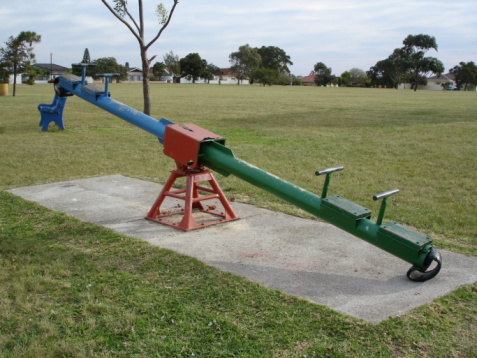
See-saw 

The general architecture of a seesaw, particularly the reality that it rests on the floor, ensures that the platform can never spin completely 360 degrees; however, the surface can revolve within very restricted constraints.

Imagine the clockwise rotating behaviour of a seesaw from the front, with a toddler on the left and an adolescent on the right, to demonstrate the consequences of torque. 

pivotal see saw 2 request picture id104879257?b=1&k=20&m=104879257&s=170667a&w=0&h=PhrFfRNeDE9UA1zolwFhutvvQ1oR4JcrbXAdwunK9e8=
Image credit: Snappy Goat

The torque on either side must be adjusted in order for the two to be precisely balanced. Shifting mass is one option, but a movement and, as a result, this included is a more likely solution. Because the adolescent weighs precisely twice as much as the kid, the child’s this included must be precisely double as lengthy as the adolescents. 

Automobiles engine 

The flywheel of an engine produces torque, which is a spinning force. The higher an engine’s capacity to accomplish work, the more torque it produces. The testing is similar to work but differs somewhat. Torque is measured in pound-feet and newton meters because it is a vector (operating in one direction). 

In this situation, the difference is static torque, which is the sort used to compress head bolts with a screwdriver. Static torque is generally measured in foot-pounds to prevent misunderstanding. SI, on the other hand, uses newton meters to calculate both fixed and kinetic torque. 

Wrenches 

A pressure wrench is a tool for tightening nuts and screws to a certain torque level. This tool enables screws to be adjusted at the correct tension, preventing harm from overtightening or parts from breaking apart due to under-tightening. 

A pressure wrench is required if you want to undertake any serious repair on the motor or other mechanical parts. For example, overtightening fuel tank screws can quickly result in costly breakage and disastrous fluid loss. Catalytic plenum screws that are too tight might lead the plenum to break. 

Torque standards are so important to effective automobile repair that many trade guides contain them in the back-page tables with bolt position, identification, and specific specifications, in addition to the maintenance instructions. 

Projector or flexion, dial indication, button, and computerized torque wrenches are the four most common varieties, each with somewhat unique functioning concepts. The laser and scale indicators both have a basic mechanical mechanism that links to a marker that floats beyond a torque meter linked to the grip or dial indication.

The meter or dial shows the quantity of torque corresponding to the flexion of the wrench’s bent grip when pressure is imparted to it. When operating in dark all the regions, you’ll want a big pointer or meter panel if you’re purchasing a beam- or keypad kind. 

Gyroscopes 

A gyroscope is made up of a flywheel, which is a wheel-like disc attached to an axle, which is positioned on a bigger ring perpendicular to the wheel’s axis. The architectural solidity of the gyroscope is provided by an exterior circle in the same plane as the spinning, and the gyroscope can have multiple such concentric rings.

The spinning and axle, on the other hand, are the center of attention. The axle’s one end is usually linked to something external, whereas the opposite end is allowed to drift. Gravity has a propensity to pull the detached end of the axle lower once the flywheel starts spinning, turning it on an axis orthogonal to the flywheel’s.

The gyro may topple over as a result, but instead, it starts spinning a third axis, a horizontal axis orthogonal to both the axis of the flywheel and the direction of gravitation. As a consequence, it spins on three axes and stays extremely stable—that is, impervious to outside efforts to alter its equilibrium. 

A pendulum or a parachute is applying torque when swinging 

Observe the pendulum’s torque. The portion of the pendulum bob’s mass that operates throughout the curve size is the pressure that provides the restorative torque. The torque is equal to the length of the string L multiplied by the portion of the net force parallel to the arc’s radius. The torque works in the opposite direction of the angular shift, as indicated by the negative sign. 

π=-L(mgsinθ)

A person riding a bicycle 

While riding a bike, the peak torque that an individual can generate is roughly equivalent to 1/3 of his body weight magnified by the size of the pedal linking rod; however, if a person stays on a seat, he has three points of help and thus the torque that he may generate is roughly equivalent to 1/3 of his body weight magnified by the size of the pedal linking rod.

The highest moment that an individual can generate by transporting its center of mass as close to the pedal’s vertical plane would be approximately 1/2 of its weight increased by the size of the pedal linking rod, according to basic math. 

Opening of door 

Torque is intuitively understood by everyone who has actually opened a door. While opening a door, the individual pushes on the side of the door that is furthest from the joints. It takes a lot more power to push on the part nearest to the joints.

Even though the labour is the same in both circumstances (the bigger force is delivered over a shorter radius), people like to use less force, which is why the door handle is usually located in the middle. 

Frequently asked questions| FAQs 

Ques. What is torque and what are some examples? 

Ans. Torque is a winding force that enables anything to revolve around an axis or another point in general. Torque is defined as the force that causes a wheel to revolve around an axle. 

Torque is defined as the rotating force of an engine in basic words. It varies from horsepower in that torque relates to how much work an engine can do, whereas horsepower refers to how quickly that work can be done. 

Ques. What is static torque? 

Ans. The term “static torque” refers to a torque that does not create an angular acceleration. Since the door does not rotate on its joints regardless the force provided, someone pushing on it applies a static torque to it. 

Dynamic torque is carried by the drive shaft of a racing vehicle speeding from the beginning line since it must produce an angular acceleration of the tires provided that the car is moving along the course. 

The vocabulary used to describe torque can be a bit perplexing. Engineers frequently use the terms moment and moment of force identically. The instant arm refers to the radius at which the pressure operates. 

Ques. When it comes to torque, what is the distinction between static and kinetic torque? 

Ans. Static torque is provided manually and is done slowly. A powered tool is used to provide variable torque at a high rate of velocity. 

Also Read: