Hygroscopic vs Hydroscopic: 7 Important Comparison

Hygroscopic vs Hydroscopic

The terms hygroscopic and hydroscopic may sound similar but their meanings completely differ from one another.

Hygroscopic substance refers to the substance that can take and hold moisture from the surroundings. Hydroscope is an instrument used to see objects deep underwater. This article discusses about hygroscopic vs hydroscopic substances in detail.

Hygroscopic vs Hydroscopic

Hygroscopic vs Hydroscopic:

AspectHygroscopyHydroscopy
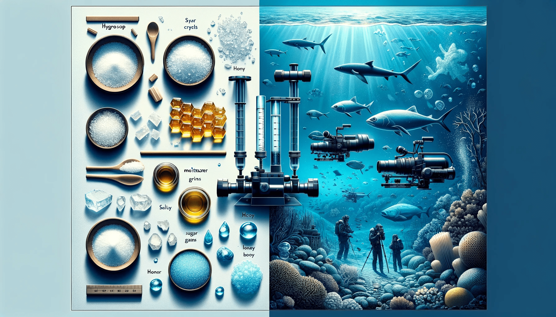
DefinitionThe ability of a substance to absorb moisture from the surrounding environment.The practice of observing objects underwater.
Scientific RelevanceSignificant in chemistry, physics, material science, meteorology, and various industries.Relevant in marine biology, underwater archaeology, and maritime activities.
Key ExamplesSubstances like salt, sugar, honey, and certain chemicals.Instruments like traditional and modern hydroscopes.
ApplicationsUsed to control moisture in food and pharmaceuticals, in humidity sensors, and in maritime cargo management.Used for studying marine life, archaeological underwater exploration, and inspecting underwater structures.
Instruments/ToolsHygrometers and other moisture measuring devices.Hydroscope and various underwater viewing devices.
Historical BackgroundLong-standing concept in the scientific study of moisture absorption.Originates from the invention attributed to Hypatia of Alexandria for underwater observation.
Physical Process InvolvedInvolves absorption or adsorption of water molecules.Involves visual observation through a medium (like water) using specialized equipment.
Industries ImpactedFood processing, pharmaceuticals, construction, and maritime industries.Marine biology, maritime exploration, and underwater archaeology.

Hygroscopic substances

Hygroscope refers to the phenomenon of attracting water molecules via absorption or adsorption. Hygroscopic substances are capable of taking away moisture from the surroundings and holding it. This decreases the relative humidity of the surrounding. The relative humidity of substance is directly proportional to the amount of moisture the substance can hold.

Engineering materials like ABS, Cellulose , Nylon etc are hygroscopic in nature.In some composites, due to difference in hygroscopic properties of two materials, there can be detrimental effects such as stress concentration. The amount of moisture taken by a substance is a function of temperature and humidity of the surrounding.

The rate of transfer of moisture decreases as it approaches equilibrium. This happens because of two reasons- the driving force behind moisture transfer decreases and the diffusional resistance to mass transfer increases as the surface taking up moisture nears to equilibrium.

Hygroscopic vs hydroscopic
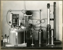
Image: Apparatus for measuring hygroscopicity of fertiliser

Image credits: Wikipedia

Storage of hygroscopic materials

Hygroscopic materials are usually stored in sealed bags. These bags are simply kept in those places where the moisture content has to be regulated. A common example is silica gel which is used to take away moisture content from the products such as water bottles, lunchboxes, water filters etc.

If these materials are not properly stored, the desired moisture content will not be achieved. Moisture content is an essential factor for determining a machine’s life. If it is not regulated properly then simply because of improper moisture content, life of machines will be altered.

Hygroscopic materials in different pressure conditions

The partial pressure of hygroscopic materials and the ambient pressure can affect the moisture of the system directly.

When the material is subjected to high pressure (isothermally beyond saturation point), then the specific humidity will decrease and relative humidity will keep on increasing. The added moisture will affect material’s quality. An example of such pressure fed system is pneumatic system wherein the hygroscopic material is conveyed through air.

When the material is subjected to negative pressure, the specific humidity remains constant and relative humidity decreases as pressure of the air in conveyer decreases.

Applications of deliquescent materials

The phenomenon of absorbing moisture up to such an extent that the substance dissolves completely in the water to make a solution. Liquids like Sulfuric acid and and salts like Sodium Chloride are examples of deliquescent substances.

In chemical industries, deliquescent materials are used for absorbing water content from chemical reactions. These materials are also known as desiccants. Desiccants like silica gel are used for absorbing moisture from the surrounding environment.

Hydroscopy

Hydroscopy is completely different from hygroscopy. Hydroscopy is the practice of looking and observing things underwater. This can be done by using the instrument called hydroscope. The original hydroscope was invented by Greek scholar and scientist philosopher, Hypatia of Alexandria.

Hydroscope itself is not any instrument. Hydroscope refers to the type of any instrument that is used to measure properties related to water. The hydroscope is generally made out of tubes and a transparent cap at the end made of plastic or glass for viewing.

It is difficult for humans to see underwater without using hydroscope. When we try looking underwater with naked eye, water rushes on the surface of eyeball and distorts the light coming to the pupil. Hydroscope prevents this distortion by providing a transparent material which allows light to enter the eye and avoiding contact with water. If required, we can also achieve magnification underwater.  

Examples of hydroscopy

Complexity of hydroscope varies from application to application. It can be as simple as a tube with two lens and as complex as a computer controlled lens with variable magnification.

Some examples of hydroscopy are as follows-

  • For viewing objects near the surface of oceans, a long tube is fitted with lenses so as to see the objects that can’t be seen otherwise.
  • In defence practices, subsurface water is detected by the use of surface nuclear magnetic resonance technique.

Applications of hydroscope

Hydroscopy is an important technique that allows us to study aquatic life and perform underwater tasks. Everything that requires deep water excursions is achieved by using hydroscope.

Following are the applications of hydroscope-

  • Scientists use hydroscopes for looking at marine life which dwells deep inside the ocean. Many marine animals and plants have been discovered with the use of hydroscopes.
  • Archaeologists use hydroscopes to search for ancient remains which might have submerged deep underwater.
  • Hydroscopy is used for inspection of ship hulls and underwater pipelines to check for corrosion.
  • Rescue missions in caves which are flooded by seawater.

Chiller Work: 7 Important Facts You Should Know

1024px Kompresors.svg 300x192 1

Chillers are machines used to dehumidify or cool fluids. There are various types of chillers classified on the basis of working fluid used, working mechanism used etc.

This article explains how does a chiller work, different types of chillers used in industry and general information about compressors used in air cooled chillers.

How does an air-cooled chiller work?

Ever seen multiple fans installed on the top of a building? They are used for cooling purposes inside the building. These fans are a part of a bigger system known as air cooled chiller.

Chiller is a machine that absorbs heat using vapour compression cycle, vapour absorption cycle or vapour adsorption cycle. The cool fluid can be passed through a heat exchanger for further applications. Concepts of thermodynamics are used in air cooled chillers to cool the fluid or dehumidify air.

Chillers collects heat from water and sends it back to air handling unit which uses cool water for its operation. After AHU’s operation, the water temperature rises and is brought back to the air chiller.

How does an industrial chiller work?

The main purpose of industrial air chiller is to cool the water and send it back to the AHU (Air Handling Unit). After AHU does its specified task, the water inside the AHU becomes warm. This warm water is sent back to the inlet of chiller. This cycle continues till the end of AHU’s operation.

The air chiller absorbs heat from the processed water that comes into the inlet of the chiller. Heat is absorbed with the help of chiller’s evaporator.

After the liquid refrigerant passes through evaporator, its phase changes to gas and pressure decreases in this process. After compression, the refrigerant that leaves has high pressure and high temperature.

This gas enters the condenser where it is cooled by condensing fans. The cooling fans blow away the heat into ambient hence it is suggested to install air chillers outside the room or at a place where dumping heat is not an issue.

An industrial air chiller has following components- Evaporator, condenser, compressor, pump and cooling fans.

  • Evaporator-It takes away heat from the water to change the phase from liquid to gas.
  • Compressor-Temperature and pressure of the gas is increased by compressing the gas in compressor.
  • Condensing fans/cooling fans-The cooling fans blow away the heat from the refrigerant reducing the temperature of gas.
  • Condenser-The phase changes back to liquid inside the condenser.

What are industrial chillers used for?

Industrial chillers are used for cooling mechanisms, products and a wide range of machinery. It can be centralized where one chiller can be used for multiple applications or decentralized where each and every application has one dedicated chiller.

Chillers are used in plastic industries, metal cutting work oils, injection and blow moulding, cement processing. They are also used in gas turbine cooling system, high heat applications such as MRI and lasers in hospitals.

Liquid cooled chillers are used for indoor operations due to as liquid absorbs the rejected heat. Air cooled chillers are meant for outdoor installations because the heat is rejected in the ambient. Hence, most air cooled chillers are installed at the top of buildings.

Types of compressors used in air cooled chillers

There are various types of compressors that can be used in chillers depending on the load requirements in the application. Following are the compressors that can be used in chillers-

  • Reciprocating compressor-A simple positive displacement pump which used a piston to deliver gas at high pressure. The gas enters the cylinder in the suction stroke when the piston is at bottom dead centre. The gas is compressed in the next stroke when the piston move towards the top dead centre. Compressed gas leaves through the delivery valve. This type of compressors deliver compressed gas in pulsations.
  • Rotary screw compressor-Rotary compressors are used in large sized refrigeration applications such as chillers. These have rotary type positive displacement mechanism and provide continuous delivery of compressed gas unlike reciprocating compressors which have pulsations. Rotary compressors are more quiet in operation.  
  • Vane compressor-Most common type of compressor is the vane compressor. It uses centrifugal force to compress the gas. These compressors uses vanes instead of helical screws to generate compressed air.
  • Scroll compressor-A scroll compressor uses two spiraled scrolls for compressing the gas or refrigerant. Usually one scroll is fixed and other orbits with a little offset without rotating. The tapped gas between the scrolls get compressed due to the relative motion between scrolls. Its efficiency is slightly higher than reciprocating compressors.
how does a chiller work
Image: Reciprocating compressor
Image credit: No machine-KompresorsCC BY-SA 3.0

Water cooled chillers

As the name suggests, water cooled chillers use water instead of air for cooling. It uses latent heat for cooling purposes.

External cooling towers supply water that is used to cool the gaseous refrigerant in the condenser. Inside the condenser, refrigerant’s phase changes. The gaseous refrigerant turns into liquid refrigerant and is then re-circulated in the system.

Advantages and disadvantages of water cooled chillers

Every mechanical component has its own pros and cons. Designers have to make a trade off between pros and cons to make the best design suitable for the particular application. Following are the advantages and disadvantages of water cooled chillers

Advantages of water cooled chillers-

  • They are more efficient than air chilled coolers.
  • They don’t create much noise while operating.
  • They can be used in both small scale and commercial scale applications.

Disadvantages of water cooled chillers-

  • Due to continuous requirement of water, water cooled chillers are not feasible to use in areas having water shortage problems.
  • As the number of components are increased (cooling tower and pumps), installation cost of water cooled chillers is more.

Vapour compressed chillers vs vapour absorbed chillers

Vapour compressed and vapour absorbed chillers are both air cooled chillers. The principle difference between vapour compressed chiller and vapour absorbed air chiller is the way of cooling.

Vapour compressed chillers Vapour absorbed chillers
Vapour compressor chillers use following components- evaporator, condenser, compressor and an expansion unit. Refrigerant extracts unwanted heat, this refrigerant is pumped by the action of compressor. Vapour absorption chillers use same components as vapour compressed chillers except compressor. Instead of compressor, there is an absorber, generator and a pump. Heat source itself is used to pump refrigerant around the system for cooling purposes.
Table: Difference between vapour compressed chillers and vapour absorbed chillers

It is clear that vapour absorbed chiller has more parts but it is cheaper to operate as it does not need any compressed air for operation.

Wind Turbine Efficiency: 11 Complete Quick Facts

Windmills D1 D4 Thornton Bank 194x300 1

Wind turbine energy production is a growing field of electricity generation; in 2020, the total wind power capacity in the world is 743GW. As the wind plants are producing less pollution, the demand for wind power generation is growing.

The efficiency of a wind turbine depends on many factors, like the type of turbine, the blade geometry, available wind velocity etc. 59% is the maximum efficiency that can be achieved by a wind turbine. The practical efficiency of a wind turbine varies between 30 -45%, and it may rise to 50% during peak wind.

If the turbine is working at 100% efficiency, the wind speed after striking the turbine becomes zero, which is impossible.  

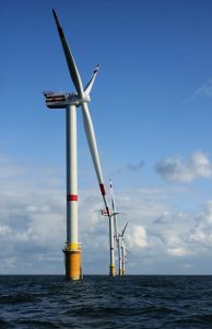
wind turbine efficiency
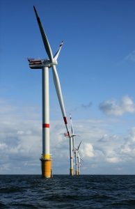
Windt turbine Credit : https://commons.wikimedia.org/wiki/File:Windmills_D1-D4_(Thornton_Bank).jpg
Wind turbine
Wind turbine Credit:https://commons.wikimedia.org/wiki/File:Wind_turbine.gif

Wind turbine efficiency formula

The calculation of efficiency is essential; the efficiency helps to compare the performance of different wind turbines and optimum wind speed for maximum efficiency.

Co-efficient of power is the more common word for efficiency of the wind turbine. The Cp is defined as,

gif

The amount of electricity produced by a wind turbine can be calculated from the generator output. The below equation calculates the input kinetic energy,

Where,

gif

A is the covered area of the wind turbine, V is the wind speed, ρ is the air density.

The Cp value varies with respect to the wind speed; hence the efficiency of the wind turbine varies while operating.

Further, the Cp depends on turbine parts, i.e. the turbine blades, shafts and generator. Therefore, the multiplication of aerodynamic efficiency of blades, mechanical efficiency of the shaft and electrical efficiency of generator provide the value of Cp.

Maximum efficiency of wind turbine

The maximum possible efficiency of the wind turbine is proposed by Albert Betz, a German physicist, in 1919. It provides insight into the maximum possible turbine efficiency.

The Betz’s limit shows that 59.3% is the maximum possible efficiency of a wind turbine. Hence, the turbine efficiency never exceeds 59%, including all other losses it comes to 35-45% value in practical cases.  

Let’s assume that the efficiency of a wind turbine is 100% that means the turbine consumes all the air energy. If it happens, the velocity of air after passing the turbine becomes zero. That means the air is not flowing, which hinders the further flow of air. Thus, this is an impossible situation.

Now, if the inlet and exit air velocity are the same, that means no energy is extracted, which gives 0% efficiency to the turbine. Hence the maximum possible turbine efficiency is somewhere between 0 and 100%, excluding these limits.

Betz proved that the maximum possible efficiency is 59.3% for a wind turbine with maths and solid physics.

Types of wind turbines and their efficiencies

A variety of wind turbines are available according to the axis of rotation and design of blades. The most commonly used wind turbine is the Horizontal axis wind turbine. However, other kinds of turbines are also used for appropriate conditions. The different types of turbines are,

Let’s discuss the efficiency of these turbines separately,

Horizontal axis wind turbine (HAWT) efficiency

The horizontal axis wind turbines are commonly used for large plants, where enough space and wind is available. The axis of rotation of the turbine blade is parallel to the earth surface.

The efficiency of HAWT varies between 35-50%. Currently, HAWT has the highest efficiency.

The captured wind energy by wind turbine depends on the area covered by the turbine blades. For a HAWT, the area is calculated as follows,

A = πL2

Where, L is the length of blade. The length varies between 20 to 80 meters.

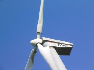
Usually these wind turbines are used for large production plants. Most common horizontal wind turbine is 3 bladed, and the colour of turbines usually white for visibility by aircraft.

Horizontal
HAWT Credit: https://commons.wikimedia.org/wiki/File:Micon-Turbine.JPG

Vertical axis wind turbine (VAWT) efficiency

The vertical axis wind turbines are commonly used for small energy production where the space is constrained. The axis of rotation of blades of vertical axis wind turbines is perpendicular to the Earth surface.

The efficiency of VAWT is less compared to HAWT. 

As discussed, the efficiency depends on the area of turbine blades exposed to wind. For VAWT, the area exposed is,

A = DH

Where D and H are the diameter and height of the blades.

Different kinds of VAWT are available. Darrius wind turbine and Savonius wind turbine are common VAWT. The efficiencies of these two are discussed below.

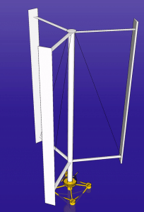
Vertical Axis Wind Turbine offshore
Vertical axis wind turbine. Credit: https://upload.wikimedia.org/wikipedia/commons/1/1f/Vertical_Axis_Wind_Turbine_offshore.gif

Darrius wind turbine efficiency

Darrius wind turbine is a VAWT.

The efficiency of the Darrius wind turbine is between 30-40%. The usage of these turbines are limited even though these are having high efficiency mainly due to inability to self-start.

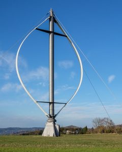
Darrius turbine is a lift based turbine. The figure shows a Darrius wind turbine. As shown below, a number of aerofoil blades are mounted on a vertical shaft that rotates. The blades are stressed only in tension for these turbines due to the curvature. The design is developed by  French engineer Georges Jean Marie Darrieus. These are commonly used near to human habitat, on the top of a building or in the centre of a road. However, the protection of the turbine is tough in extreme conditions.

Darrieus Rotor Ennabeuren 3256
Darrius wind turbine Credit:https://commons.wikimedia.org/wiki/File:Darrieus-Rotor_Ennabeuren-3256.jpg

Savonius wind turbine efficiency

Savonius wind turbine is a different type of VAWT. Unfortunately, the efficiency of these turbines is very low.

The efficiency of the Savonius wind turbine varies between 10-17%. Even though the efficiency is very low, due to the simple structure and reliability of the turbine, these are used to produce a small amount of electricity in appropriate locations.  

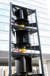
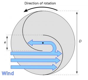
Savonius turbine is drag based turbine. The figure shows an actual Savonius wind turbine. The top view of the blade is also shown in the below figure.

399px Savonius wind turbine
Savonius wind turbine Credit: https://commons.wikimedia.org/wiki/File:Savonius_wind_turbine.jpg
660px Savonius rotor en
Top view of Savonius wind turbine. Credit: https://commons.wikimedia.org/wiki/File:Savonius-rotor_en.svg

Finnish engineer Sigurd Johannes Savonius developed the Savonius wind in 1922. There are two types of blade design for Savonius wind turbine, barrel design and ice wind design. The top view barrel wind turbine is shown above. The blades are half-cylindrical; the barrels are not meeting in the centre; they are away from the centre, which enables the free motion of wind in the blade.

Bladeless wind turbine efficiency

The bladeless wind turbines are a particular type of wind turbine, these turbines don’t have revolving blades, and the turbine works based on vortex-induced vibration.

The efficiency of a bladeless wind turbine is very less compared to any other wind turbine. However, lightweight, cost-effectiveness and less maintenance are the advantages of the bladeless wind turbine. In addition, the turbine requires less space; hence, more turbines can be installed than the usual wind turbine.

Archimedes wind turbine efficiency

Archimedes wind turbine is a recently developed technology. These are small structures and can be used on rooftops, on roads, etc.

Compared to conventional wind turbines Archimedes wind turbines are more efficient. In addition, the turbine reduces many other problems related to conventional turbines. 

For example, the noise produced by Archimedes wind turbines is significantly less compared to the conventional turbine. The shape of the turbine is modelled similar to the spiral of a Nautilus shell. This shape enables the turbine to self-adjust the turbine face according to the wind flow. 

Factors affecting wind turbine efficiency

The efficiency of wind turbines are already discussed above, from that the factors affecting turbine efficiency are,

  • The wind speed.
  • The air density.
  • Blade radius.
  • Type of wind turbine

Wind turbine efficiency comparison

Let’s conclude the wind turbine efficiency here. The wind turbine efficiency is tabulated below.

Turbine Efficiency
Horizontal axis wind turbine 30-45
Vertical axis wind turbine 10-40
Darrius wind turbine 30-40
Savonius wind turbine 10-17
bladeless wind turbines Very less

For more posts on Mechanical Engineering, please follow our Mechanical page

Steam Turbine Efficiency: 15 Important Facts You Should Know

29952475153 c87b98e738 w 300x200 1

Steam turbines convert kinetic energy/pressure energy to mechanical energy; these are used for electricity production by coupling the turbine with a generator.

The practical steam turbine efficiency varies with the turbine’s size, type, and frictional losses. Although the maximum value reaches 50% for a 1200MW turbine, small turbines have less efficiency. The efficiency of the steam turbine is maximised by expanding the steam in different stages instead of a single stage.

Impulse and reaction turbines are two types of steam turbine; the efficiency of these turbines varies. The upcoming section explains the equation of efficiencies.

Steam turbine efficiency formula

Many parameters control steam turbine efficiency. The steam turbine is equipped with a nozzle/stator and rotor. Hence, the efficiency of each component affects turbine efficiency.

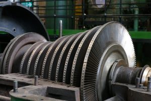
steam turbine efficiency
Steam turbine Credit: https://www.flickr.com/photos/elsie/29952475153

The basic formula for the calculation of turbine efficiency is

Efficiency = Work done on turbine/input kinetic energy of steam

First, let’s define some of the efficiencies.

Blade efficiency

The blade efficiency is defined as, The ratio of work done on the blades divided by the input kinetic energy.

Nozzle efficiency

Each stage of the impulse turbine is equipped with a nozzle and blades.  Hence, overall efficiency is affected by the nozzle efficiency,

The nozzle efficiency is defined as; the ratio of output kinetic energy from the nozzle to the difference in the inlet and exit enthalpies of the steam.

Stage efficiency

The overall efficiency of the combination of nozzle and blade stage is known as stage efficiency.

The stage efficiency is obtained by multiplying the blade efficiency with nozzle efficiency.

Isentropic efficiency

The isentropic efficiency is thermodynamic efficiency. This is also known as the 2nd law efficiency of the turbine.

The isentropic efficiency is the ratio of actual work produced in the turbine to the maximum possible work produced if the ideal isentropic process has occurred.

Efficiency of impulse turbine

The impulse turbine utilises the kinetic energy of the steam and converts it to mechanical energy. The steam pressure energy is converted to kinetic energy with the help of a nozzle before entering the rotor blades in impulse turbine.

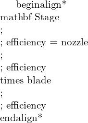
The final efficiency of one stage, i.e. one nozzle and blade set of impulse steam turbine, is given as,

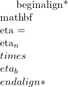
(1)    \\begin{align*} \\mathbf{ Stage\\;\\; efficiency = nozzle\\;\\; efficiency \\times blade\\;\\; efficiency} \\end{align*}

(2)   \\begin{align*} \\mathbf{ \\eta = \\eta_n \\times \\eta_b}  \\end{align*}

Where blade efficiency is,

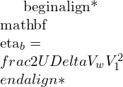
(3)   \\begin{align*} \\mathbf{\\eta_b = \\frac{2U\\Delta V_w}{V_1^2} }\\end{align*}

Where, U is the blade speed, V1 is the velocity of inlet steam from nozzle and ΔVw  is the difference between whirl component of inlet and exit velocity

And Nozzle efficiency is,

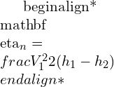
(4)   \\begin{align*} \\mathbf{ \\eta_n = \\frac{V_1^2}{2(h_1-h_2)}} \\end{align*}

Where, h1 and h2 is inlet and exit enthalpy of the steam respectively.

Let’s do the detailed analysis of stage efficiency,

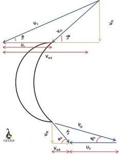
The velocity triangle of impulse turbine is given below.

blades
Velocity triangle of impulse turbine

In the figure, the steam enters from the top and leaves through the bottom.

Vr is the relative velocity of steam

V is the absolute velocity of steam

Vw is the whirl component of steam velocity and Vf is the flow component of steam velocity.

U is the blade velocity

Α is the guide vane angle and β is the blade angle

The suffix 1 and 2 represents inlet and exit, respectively.

The whirl component is helping to rotate the blade and the flow component helps the flow of steam over the turbine. Hence, a momentum is created in the direction of blade rotation due to the difference in whirl component. Applying the law of moment of momentum gives

(5)    \\begin{align*}  Torque = m(r_1V_{w1}-r_2(-V_{w2})) \\end{align*}

The r1=r2=r for an impulse turbine.

Hence,

(6)    \\begin{align*}  T = mr\\Delta V_w \\end{align*}

Now,

(7)    \\begin{align*}  Power = T \\times \\omega \\end{align*}

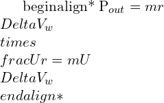
(8)    \\begin{align*}  P_{out} = mr \\Delta V_w \\times \\frac{U}{r} = mU \\Delta V_w \\end{align*}

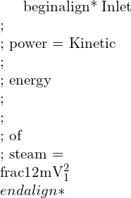
(9)    \\begin{align*}  Inlet \\; \\; power = Kinetic \\; \\; energy \\; \\; \\; of \\; steam =\\frac{1}{2}mV_1^2 \\end{align*}

Hence the final blade efficiency is

(10)    \\begin{align*}  \\eta_b =\\frac{mU\\Delta V_{w}}{\\frac{1}{2}mV_1^2} \\end{align*}

(11)    \\begin{align*}  \\eta_b =\\frac{2U\\Delta V_{w}}{V_1^2} \\end{align*}

Substituting blade efficiency and nozzle efficiency in stage efficiency equation,

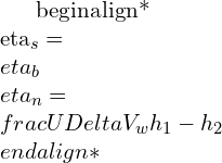
(12)    \\begin{align*}  \\eta_s=\\eta_b \\eta_n = \\frac{U \\Delta V_w}{h_1-h_2} \\end{align*}

Now let’s find out the ΔVw,

(13)    \\begin{align*}  \\Delta V_w = V_{w1}-(-V_{w2} ) \\end{align*}

(14)    \\begin{align*}  \\Delta V_w = V_{w1}+V_{w2} \\end{align*}

From velocity triangle,

(15)    \\begin{align*}  V_{w1}=V_{r1} cos \\beta_1+U\\end{align*}

(16)    \\begin{align*}  V_{w2}=V_{r2} cos \\beta_2-U \\end{align*}

Substituting these give,

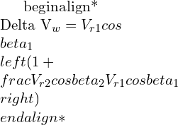
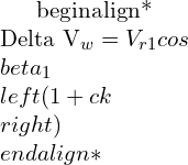
(17)    \\begin{align*}  \\Delta V_{w}=V_{r1} cos \\beta_1\\left ( 1+\\frac{V_{r2} cos \\beta_2}{V_{r1} cos \\beta_1} \\right ) \\end{align*}

(18)    \\begin{align*}  \\Delta V_{w}=V_{r1} cos \\beta_1\\left ( 1+ck \\right ) \\end{align*}

Where,

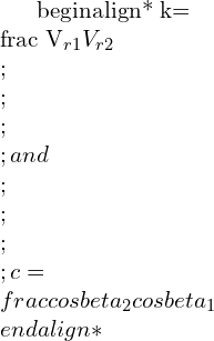
(19)    \\begin{align*}  k= \\frac {V_{r1}}{V_{r2}} \\;\\;\\;\\; and \\;\\;\\;\\; c = \\frac{cos \\beta_2}{cos \\beta_1} \\end{align*}

Applying ΔVw on blade efficiency equation,

(20)    \\begin{align*}  \\eta_b=\\frac{2UV_{r1} cos \\beta_1\\left ( 1+ck \\right )}{V_1^2} \\end{align*}

From velocity triangle,

(21)    \\begin{align*}  \\eta_b=\\frac{2U(V_1 cos\\alpha_1-U)\\left ( 1+ck \\right )}{V_1^2} \\end{align*}

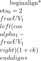
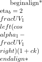
(22)    \\begin{align*}  \\eta_b=2\\frac{U}{V_1}\\left( cos\\alpha_1-\\frac{U}{V_1}\\right) ( 1+ck ) \\end{align*}

k is the ratio of relative velocities, for  perfect smooth blades, k = 1 and otherwise, k is less than 1.

Differentiating the efficiency equation with respect to U/V1 and equating to zero gives the criteria for maximum turbine efficiency. U/V1 is known as blade speed ratio.

Efficiency of Reaction turbine

Let’s analyse the efficiency of reaction turbine by analysing the most commonly used Parson’s reaction turbine.The degree of reaction of parson turbine is 50%. The rotor and stator are symmetrical and velocity triangles are similar.

The final blade efficiency equation of Parson’s Turbine is given below,

(23)    \\begin{align*} \\mathbf{ \\eta_b=\\frac{2U(2V_1cos \\alpha_1-U)}{V_1^2-U^2+2V_1Ucos \\alpha_1}} \\end{align*}

The reaction turbine uses the reaction force to generate the power. The steam flow over the stator, the stator itself acts as convergent nozzle. The flow to rotor is controlled by fixed vanes known as stator. In impulse turbine the pressure remains constant while the steam flows over the rotor, however, in the reaction turbine the pressure drops while steam flows over the rotor.

Let’s derive the efficiency equation.

Figure shows the velocity triangle of Parson’s reaction turbine.

Parson
Velocity triangle of Parson’s turbine

In the reaction turbine, the primary objective is to find out the total energy supplied by the steam.

In the case of reaction turbine, the energy is supplied in the form of pressure energy also, additional to the kinetic energy. Therefore, the equation of input energy includes the term for kinetic energy and pressure energy. The pressure energy term can be represented with the change in total relative velocity.

Finally, the total input energy

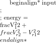
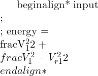
(24)    \\begin{align*} input \\;\\; energy =\\frac{V_1^2}{2}+\\frac{V_{r2}^2-V_{r1}^2}{2} \\end{align*}

For parson’s turbine, V1 = Vr2, V2 = Vr1, α12 and α21

Applying these conditions,

(25)    \\begin{align*} input \\;\\; energy =\\frac{V_1^2}{2}+\\frac{V_{1}^2-V_{r1}^2}{2} \\end{align*}

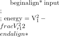
(26)    \\begin{align*} input \\;\\; energy = {V_1^2}-\\frac{V_{r1}^2}{2} \\end{align*}

From input velocity triangle, applying Cosine rule,

(27)    \\begin{align*} V_{r1}^2=V_1^2+U^2-2V_1Ucos \\alpha_1 \\end{align*}

Hence, the input energy equation becomes,

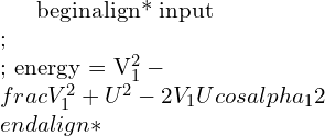
(28)    \\begin{align*} input \\;\\; energy = {V_1^2}-\\frac{V_1^2+U^2-2V_1Ucos \\alpha_1}{2} \\end{align*}

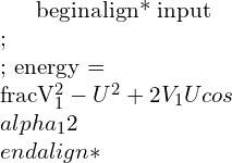
(29)    \\begin{align*} input \\;\\; energy = \\frac{V_1^2-U^2+2V_1Ucos \\alpha_1}{2} \\end{align*}

The work done is similar to impulse turbine,

(30)    \\begin{align*} workdone= U \\Delta V_w \\end{align*}

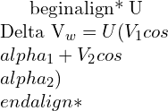
(31)    \\begin{align*} U \\Delta V_w=U(V_{w1}+V_{w2} ) \\end{align*}

(32)    \\begin{align*} U \\Delta V_w=U(V_{1}cos \\alpha_1+V_{2}cos \\alpha_2 ) \\end{align*}

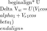
(33)    \\begin{align*} U \\Delta V_w=U(V_{1}cos \\alpha_1+V_{r1}cos \\beta_1 ) \\end{align*}

Where,

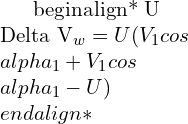
(34)    \\begin{align*} V_{r1}cos \\beta_1 = V_1 cos \\alpha_1-U \\end{align*}

Hence,

(35)    \\begin{align*} U \\Delta V_w=U(V_{1}cos \\alpha_1+V_1 cos \\alpha_1-U) \\end{align*}

Finally, ,

(36)    \\begin{align*} U \\Delta V_w=U(2V_{1}cos \\alpha_1-U) \\end{align*}

Hence the equation efficiency,

(37)    \\begin{align*} \\eta_b=\\frac{2U(2V_1cos \\alpha_1-U)}{V_1^2-U^2+2V_1Ucos \\alpha_1} \\end{align*}

Condition for maximum efficiency of steam turbine

It is always better to operate the turbine in maximum efficiency.

By analysing the efficiency equation explained above, the variable that we can change is U/V1 , hence by differentiating the equation with respect to U/V1 and equating it to zero yields the condition for maximum efficiency.

Condition for maximum efficiency of impulse turbine

The equation for maximum efficiency of impulse turbine is,

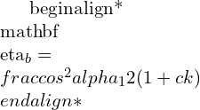
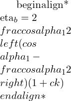
(38)    \\begin{align*} \\mathbf{ \\eta_b=\\frac{cos^2 \\alpha_1}{2}(1+ck)}\\end{align*}

Now, let’s derive the equation for maximum efficiency.

The blade efficiency equation of impulse turbine is,

(39)    \\begin{align*} \\eta_b=2\\frac{U}{V_1}\\left( cos\\alpha_1-\\frac{U}{V_1}\\right) ( 1+ck )\\end{align*}

Differentiating it with respect to , For simplification let’s take ρ = U/V1

Hence,

(40)    \\begin{align*} \\frac{d \\eta_b}{d \\rho}=2(1+ck)\\left[\\left(cos \\alpha_1-\\frac{U}{V_1} \\right )-\\frac{U}{V_1} \\right ]\\end{align*}

Equation it to zero gives,

(41)    \\begin{align*} 2(1+ck)\\left[\\left(cos \\alpha_1-\\frac{U}{V_1} \\right )-\\frac{U}{V_1} \\right ] = 0\\end{align*}

(42)    \\begin{align*} \\frac{U}{V_1} = \\frac{cos \\alpha_1}{2}\\end{align*}

This is the condition for maximum efficiency.

Applying this condition to efficiency equation yields the maximum blade efficiency.

(43)    \\begin{align*} \\eta_b=2\\frac{cos \\alpha_1}{2}\\left( cos\\alpha_1-\\frac{cos \\alpha_1}{2}\\right) ( 1+ck )\\end{align*}

(44)    \\begin{align*} \\eta_b=\\frac{cos^2 \\alpha_1}{2}( 1+ck )\\end{align*}

If blades are equiangular, β12, hence c = 1, and for smooth blades k=1.

Finally, the maximum efficiency of impulse turbine with equiangular smooth blades is,

(45)    \\begin{align*} \\eta_b={cos^2 \\alpha_1}\\end{align*}

Condition for maximum efficiency of reaction turbine

The equation for maximum efficiency of parson’s reaction turbine is,

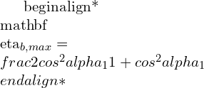
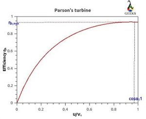
(46)    \\begin{align*} \\mathbf{ \\eta_{b,max}=\\frac{2cos^2 \\alpha_1}{1+cos^2 \\alpha_1}}\\end{align*}

Now, let’s derive the equation.

The efficiency equation of Parson’s reaction turbine is,

(47)    \\begin{align*} \\eta_b=\\frac{2U(2V_1cos \\alpha_1-U)}{V_1^2-U^2+2V_1Ucos \\alpha_1}\\end{align*}

 Let’s take ρ =U/V1 

Then,

(48)    \\begin{align*} \\eta_b=\\frac{2 \\rho(2cos \\alpha_1- \\rho)}{1-\\rho^2+2 \\rho cos \\alpha_1}\\end{align*}

Differentiating this with respect to ρ

(49)    \\begin{align*} \\frac{d\\eta_b}{d \\rho}=\\frac{(1-\\rho^2+2 \\rho cos \\alpha_1)(2(2cos \\alpha_1- \\rho)-2 \\rho)-2 \\rho(2cos \\alpha_1 - \\rho)(-2 \\rho+2cos \\alpha_1)}{(1-\\rho^2+2 \\rho cos \\alpha_1)^2}\\end{align*}

Equating the above equation to zero yields,

(50)    \\begin{align*} \\rho = cos \\alpha_1\\end{align*}

Applying this on efficiency equation yields the maximum efficiency,

(51)    \\begin{align*} \\eta_{b,max}=\\frac{2cos^2 \\alpha_1}{1+cos^2 \\alpha_1}\\end{align*}

Steam turbine efficiency curve

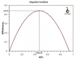
The curve between ρ and  is efficiency curve.

The efficiency curve for equiangular smooth impulse turbine for α=20o is shown below,

Impulse

The efficiency curve of parson’s reaction turbine for α=20o is shown below,    


Parsons

Factors affecting steam turbine efficiency

Now, we can easily the take out the factors affecting the steam turbine by looking into the efficiency equation.

The factors affecting steam turbine,

  • The blade angle (α1)
  • Inlet steam velocity (V1)
  • The smoothness of turbine blade (k)
  • Blade angle on the rotor.
  • The blade velocity (U)

Thermal efficiency of steam turbine

The steam power plants are based on Rankine cycle. Hence, the efficiency of the plant is calculated based on the Rankine cycle

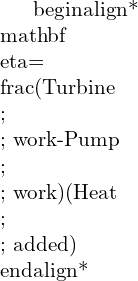
The thermal efficiency of steam turbine power plant is defined as,

(52)   \\begin{align*} \\mathbf{\\eta= \\frac{(Turbine\\;\\; work-Pump\\;\\; work)}{(Heat\\;\\; added)}}\\end{align*}

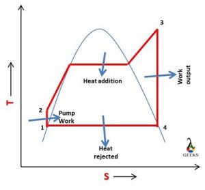
Rankine

The figure shows the ideal Rankine cycle, from the figure the thermal efficiency can be calculated as,

(53)   \\begin{align*}\\eta= \\frac{(h_3-h_4)-(h_2-h_1)}{(h_3-h_2)}\\end{align*}

How to calculate steam turbine efficiency?

The efficiency is the ratio of obtained work to given work.

The efficiency of steam turbine can be calculated by measuring the amount of work produced by the turbine to the amount of energy supplied. The supplied energy depends on the steam input, and output power depends on the turbine.

The equation to calculate the turbine efficiencies are explained in previous sections.

 In a steam power plant, we calculate the efficiency by calculating the ratio amount of electricity produced to the energy equivalent of fuel burned. The steam plant efficiency depends each component, which include steam turbine, boiler, pump, electricity generator etc.

How to improve steam turbine efficiency?

The methods to improve steam turbine efficiency are,

  • Improve the design of turbine blades.
  • Minimise the friction loses.
  • Increase steam velocity, achieved by optimising the temperature and pressure of steam.
  • Minimise the leakage of steam in turbine

Heat Pump Work In Winter: 13 Important Concepts

Heat pump 300x206 1

How does a heat pump work in winter? It is always a curious question for all of us. We know that in winter the objective of heat pump is to heat the room. Let’s analyse the working of heat pump in winter.

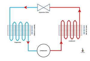
During winter, the liquid refrigerant sucks heat from outside air and becomes vapour form; the vapour refrigerant is compressed to high temperature and pressure. Then the refrigerant is allowed to pass through the room. During that period, the refrigerant releases the heat to the room, by which the room temperature increases. 

This system is a good option for places where mild winter occurs, and it can save energy compared to conventional heating. However, for severe winter, the heat pump alone is not a good alternative. The hybrid system is used in that scenario.

There different type of heat pumps are available. The classification is based on from where the heat is taken, i.e. the location of evaporator. Some of the types are :Air source heat pump, Ground source heat pump, water source heat pump etc.

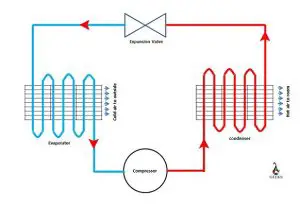
A schematic diagram of heat pump with main components are shown in figure below;

How Does A Heat Pump Work In Winter
The main components of a heat pump
small air source heat pump 4963069 960 720
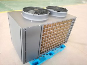
The outside unit of a small air source heat pump Credit: https://pixabay.com/de/photos/kleine-luft-w%c3%a4rmepumpe-4963069/

How does a ground source heat pump work in winter?

The temperature below few feet from the ground is at a stable temperature of 55oF irrespective of the season. Let’s see how this fact is utilised to run a heat pump.

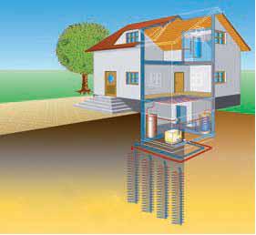
In ground source heat pumps, series of strong pipes are installed below the ground; this is the ground source heat exchanger. Coldwater from the heat pump is circulated through these pipes, and the water absorbs heat from the ground. Then, the water transfers this heat to the refrigerant in the heat pump. 

A schematic diagram is shown below.

Heat pump
Ground source heat pump Credit :https://www.flickr.com/photos/sagabardon/5086132916

The ground source heat pump eliminates the burning of fossil fuel; hence this is environment friendly. Germany, USA, Sweden, Canada, Switzerland are the main countries using this heat pump.

What temperature is a heat pump not effective?

The heat pump is not advised in all temperatures. The ambient temperature influences the effectiveness of the heat pump.

As the ambient temperature decreases the effectiveness of heat pump decreases, from the research the limiting ambient temperature is calculated as 40oF. Hence, a heat pump is advised to use when the ambient temperature is above 40oF. The heat pump becomes less effective than other heating options when the temperature reduces to 25 to 30oF.

Hence, we use an alternative system in those regions where the temperature falls below 40oF. Fossil fuel or any cheap fuel is burned to extract heat in these regions during peak winter.  

The heat pump is working between two temperature limits, room temperature and ambient temperature. Therefore, the performance of heat pump depends on both these temperature. One can assume that if the ambient temperature is low, the heat pump consumes more work to extract the heat; hence efficiency decreases.

Let’s analyze the effectiveness of heat pumps mathematically. The effectiveness of a heat pump is measured as Coefficient of performance (COP). COP is defined as

COP = (Heating effect)/(Work done to the system)

Let’s analyze the COP of a Carnot cycle. Carnot cycle is an ideal cycle that has the maximum COP.

The COP of the Carnot cycle is defined as;

COP = Thot/Thot – Tcold

Tcold is the ambient temperature, and Thot is the room temperature. Let’s assume that we set 68oF in heat pump, hence the room temperature is 68oF. Now let’s assume two conditions when the ambient temperature is 40oF and 20oF.

When these temperature conditions are applied, we get COP of 11.5 and 6.7 for the ambient temperature of 40oF and 20oF, respectively.

(Note: Care should be taken while calculating the COP, the temperatures should be in Kelvin scale or Rankine scale.)

Here, the COP is reduced when the ambient temperature is reduced. The calculated COP is for the maximum possible cycle. This COP cannot achieve in an actual cycle. Hence, we can conclude that as the ambient temperature decreases the COP of heat pump decreases.

What temperature should I set my heat pump in the winter?

This is always a concern for many of us while operating a heat pump.

The human comfort is the primary objective of a heat pump in home. From scientific researches, it is concluded that 680F is best for human comfort during winter. It is advised to reduce the operating temperature further when we use the heat pump continuously. 

Can heat pump work below freezing?

The question here is what happens when the ambient temperature is below freezing point. Is it safe to operate?

Yes we can use heat pump in freezing conditions. The freezing point of refrigerant used in a heat pump is far below the freezing point of water; hence the refrigerant in the heat pump will not freeze even though ambient temperature is below the freezing point of water.

If the question is “is it advised to use heat pump in extreme cold?” then the answer is “no it is not advised”

However, in extremely cold conditions it is not advised to use heat pump. We discussed the effectiveness of heat pumps in previous sections. When the temperature is less than 40oF, the effectiveness of the heat pump reduces; hence heat pump consumes more energy than simply burning fuel.

How can I make my heat pump more efficient in the winter?

Some tips to improve the efficiency is given below.

  • Clean the filter frequently.
  • For fast heating of the room, do not set the heat pump temperature very high.
  • Don’t heat the spaces which you are not using.
  • Perfectly close all the ventilations in the room.
  • Always provide enough space in indoor and outdoor unit of heat pump for free flow of air.
  • Only put emergency heat mode when it is an emergency.
  • Make sure that the outdoor unit is easily accessible for cleaning.

Why is my heat pump blowing cold air when the heat is on?

There are mainly three reasons that you may feel that your heat pump is blowing cold air.

  • The heat pump is working correctly, but you are feeling it cold.
  •  The heat pump started working on defrost mode.
  • The heat pump is not working correctly.

Let’s discuss each point separately.

  • The heat pump is working correctly, but you are feeling it cold.

The heat pump is working correctly; however, when the ambient temperature is very low, the heat pump’s effectiveness and the ability to increase the temperature reduces. In these situations, the heat pump is heating the air, but you do not feel it as the temperature of heated air is far below your body temperature.

Generally, the electric heating starts automatically in these situations.  

  • The heat pump started working on defrost mode.

When a heat pump is working at a very low ambient temperature, water may freeze around the outdoor unit’s coils. The complete covering of the coil with ice should be avoided. The heat pump works on reverse mode to remove this frost, i.e., it starts cooling inside and heating outside coil.

After 1-2 minutes of operation, the heat pump starts working properly when the frost is completely removed.

  • The heat pump is not working correctly.

This is a serious issue, and you should contact a technician. There are many possibilities like leakage of refrigerant, damages in valves or reduction in heat pump efficiency, etc.

 Should I run my heat pump on auto or heat?

 There are three modes in a heat pump “Heat”, “Cool,” and “Auto”. 

It is advised to set “Heat” mode rather than “Auto” mode in the winter season. This is because the “Auto” mode may cool the room on a sunny winter day, which is unnecessary, i.e., the heat pump automatically gets reversed its operation, which should be avoided.

Should I turn my heat pump off in extreme cold?

The extreme cold situation may occur in winter in many countries.

It is advised to stop using the heat pump in an extreme cold situation as the effectiveness of the heat pump decreases, which leads to increased energy consumption, as discussed above.

Usually, the heat pump comes with an electric heating facility. Hence, in an extreme cold situation, the heat pump gets switched off, and electric heating starts automatically.

How long should a heat pump run per day?

We know that the old furnace heating technique won’t run continuously for a long time. What about the heat pump?

The heat pump can run continuously throughout the day if it is required. The advanced heat pumps come with automatic sensors, which allow the heat pump to stop operating when the required temperature is achieved; it starts automatically when the temperature drops. Hence, you should not worry much about energy consumption.

However, you can reduce energy consumption by manually setting the off time in a heat pump.

How do I know if my heat pump is defrosting?

Defrosting is very common in a cold situation. Defrosting cycle may be required for the efficient working of the heat pump.

You can know that the heat pump is working on defrosting cycle if the following is observed.

  • The indoor fan of the heat pump turns off
  • The heat pump stops heating the room
  • The defrosting indicator light blinks
Ecodan outdoor unit in the snow
Frosting in outdoor unit of heat pump Credit: https://commons.wikimedia.org/wiki/File:Heat_pump_model.jpg

How do I keep my heat pump from freezing up?

The outdoor coils of the heat pump may freeze while operating.

The defrost cycle is to avoid the freezing up of the heat pump. The operation of the heat pump reverses in defrosts cycle, and during that period, the heat pump cools indoors and heat outdoor so that the ice melts. This cycle operates automatically. Within 2-3 minutes, the heat pump starts operating normally. 

How do you unfreeze a heat pump in the winter?

You can unfreeze the heat pump in the following ways,

  • Defrosting cycle. In heat pumps defrosting cycle operates automatically. 
  • Remove the frost manually; you can pump water to the frost until it is melted. Or you can chip the frost with a tool

How much frost is normal on a heat pump?

We cannot say the normal frost quantitatively.

There are two conditions when you can say that the frost is too much in a heat pump.

  • When the frost prohibit the flow of air to the heat pump
  • When the frost is staying on the coils for more than 2 hours.

If these conditions are observed, it is advised to contact an operator as the defrost cycle is not running in your heat pump.

How does a pool heat pump work in winter?

The working of a pool heat pump is similar to the air heat pump.

The pool heat pump is used to heat the water to the swimming pool. In this, the condenser transfers heat to the cold water. The other processes are similar to the room heat pump. Hence, the condenser is dipped inside the swimming pool, and the remaining unit is outside the pool.

For more posts on Mechanical Engineering, please follow our Mechanical page.

Hammer: 15 Interesting Facts To Know

1200px IKEA hammer 300x200 1

Hammer is a tool in which heavy metal is mounted on a handle,

The hammers are used for various applications, from pressing a nail into the wood to medical examination of nerves in the legs.

Different types of hammer, parts of hammers , its uses and the making of hammer is discussed in this article.

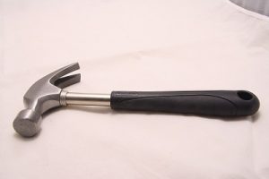
The below figure shows a typical example of a hammer.

Different types of hammer and their uses

There are different types of hammer in the industry, each have particular uses. Some of therm are listed below,

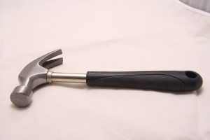
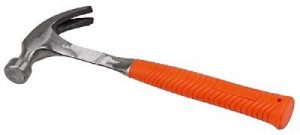
Claw hammer

The main application of a claw hammer is to push the nail into an object or pull the nail from the object.

The main difference between a regular hammer and a claws hammer is the part claw, which helps pull the nail from the object.

Claw hammer
Claw Hammer Credit: https://pixabay.com/de/photos/klauenhammer-hammer-werkzeug-2202195/

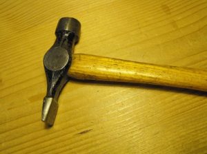
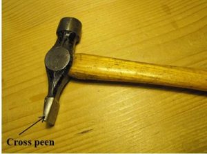
Cross peen hammer

The main applications of cross peen hammers are to push the nail into an object. The advantage of a cross peen hammer is, it can be used to hammer the nail when there is a restriction in space.

Both the surfaces are flat. The cross-section of one side of the hammer is circular, which can be used for general purposes. The other side has a rectangular section with a small cross-sectional area.  This side is known as peen. It can be used when the space is restricted.

Cross peen hammer
Cross peen hammer Credit: https://commons.wikimedia.org/wiki/File:Warrington_hammer.png

Straight peen hammer

The difference between straight and cross peen hammer is the peen is oriented 90o with each other. The application is similar to cross peen hammer.

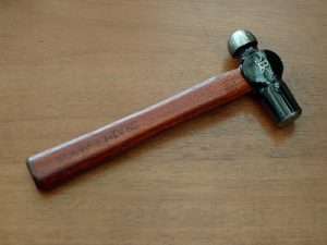
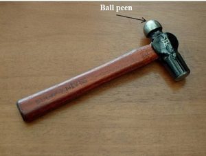
Ball peen hammer

The ball-peen hammer is also similar to a straight peen hammer. However, the peen shape is hemispherical in the case of the ball-peen hammer.

The peen surface is used for rounding the edges of metals, for example, in the case of riveting.

Ball peen
Ball peen hammer Credit: https://commons.wikimedia.org/wiki/File:Buck_Knives_Hammer_(5075278861).jpg

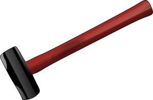
Sledge hammer

These are large hammers. The primary purpose of this is to break large rocks and concrete. Both the shape of the hammer is flat round and symmetrical. It has a large handle, and the weight is 3-16lbs

Sledge
Sledge Hammer Credit:https://pixabay.com/de/vectors/hammer-vorschlaghammer-schlitten-35244/

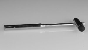
Clinical hammer

Doctors use the clinical hammer. It is also called a reflex hammer. The primary purpose of these hammers is to study nerve conduction in the human body.

The hammerhead is made up of rubber. The doctors hammer on the nerves and observe the reflexes; hence it is called the reflex hammer.

Refelx hammer
Clinical hammer Credit: https://commons.wikimedia.org/wiki/File:Percussionshammer.jpg

Club hammer

A club hammer is miniature of a sludge hammer. The weight, size, and length of the handle are less compared to the sledge hammer. However, the shape of the hammer head is similar to sledge hammer. The handles usually are wood. The weight is around 2-3 lb.

It is used for light demolishing works, chiselling, etc.

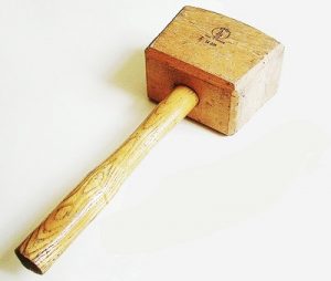
Wooden hammer or mallets

The primary purpose of the mallet is to knock the wooden pieces together or to drive chisels etc.

The hammer head is made up of wood in these hammers.

Mallet and chisel
Mallet Credit : https://commons.wikimedia.org/wiki/File:Mallet_and_chisel.jpg

Power Hammer

These hammers are powered by machinery, not with human muscle. In the power hammer, steam is used to create pressure. These are mainly used in the open die forging industry. These are derived from tripping hammers, where tripping hammers are ancient power hammers. In a power hammer, the desired position of hammer is achieved slowly. However, the hammering stroke is fast and instantaneous, hence get better hammering effects.

powerhammer
Power hammer Credit: https://commons.wikimedia.org/wiki/File:Massey_power_hammer,_Murikka_1.jpg

Parts of hammer

We can separate the parts of a hammer into two categories, Common parts, and special parts. The common parts are there in all types of hammers, and the special parts are available only in a specific hammer, and these are for special purposes.

Common parts of a hammer

Handle

The handle is a long structure in a hammer. When we buy a hammer, we will be looking into the size and shape of the hammer for the user’s comfort. The handle may be wood or steel generally. The steel handle will have the grip to hold the hammer. If the eye diameter is small for a hammer head, the handle may be made in a conical shape to have enough size toward the holding end for easy holding. The cross-sectional shape of the handle can vary; generally, the round is preferred, oval also can be used. The handles should have smooth edges for holding comfortably.

The head is the hammering part. The shape varies tremendously according to the hammer. The hammer at least has one flat side. In sludge and club hammers, both sides are flat. The clinical hammer is an exception; it does not require a flat face in the head.

The head itself has different parts. The particular parts which are peculiar to a hammer are made on the head. The different head parts are discussed below.

Face

The face is the flat surface in the hammer that is used for striking. The hammer has at least one face. The size of the face depends on the application. For example, the sledge hammer has a large face; however, the tack hammer has a small face. The sledge and claw hammer has two faces. Both the faces have the same application; we can use any of these for striking.

Neck

The portion where the head and handle are connected is known as the neck.

Throat

The throat is the portion between the neck and face. In the above figure, we can see the throat section, i.e., for claw hammers, the throat is visible. The sledge and club hammer don’t have a throat.

Cheek

It is the side of the head.

Eye

The eye is the hole that is provided in hammers to connect with the handle. In some hammers, the head and handle come as a single unit. In that case, the hammer doesn’t have an eye. Generally, for wooden handles, we can separate the handle and head. We insert the handle to the eye in these cases. The advantage is that we can change the handle if any damage is occurred to the handle, instead of changing the complete unit.

Special parts of hammer

Different hammers have unique applications. Therefore, the hammer head is made in such a way that the application is achieved easily. Such particular parts are discussed here.

Claw

The claw is provided in a claw hammer to pull out the nail. The nail head is inserted between the two openings of the claw, and then the hammer is pulled so that the nail comes out. The other face is used for the hammering of the nail as usual.

Peen

These are provided in straight, cross, and ball peen hammers. These peens have different applications. The difference between these hammers is the shape of the peen. The straight and cross peen is used when there is not enough space to hammer the nail with the large face like in corners of a wall. The ball-peen is used for rounding the metal edges.

Cross Part 1
Cross peen Credit: https://commons.wikimedia.org/wiki/File:Warrington_hammer.png
Ball part 1
Ball Peen Credit: Credit: https://commons.wikimedia.org/wiki/File:Buck_Knives_Hammer_(5075278861).jpg

Material used to make the hammer

The hammer’s head is made of strong material, as it has to withstand the repeated blow. Generally, heat-treated high carbon steel is used. The high carbon in steel provides high hardness and strength to the hammer. The heat treatment reduces the stress hence improve the fatigue strength.

Wood or steel is used to make the hammer’s handle. The steel hammers are used for small hammers, and the steel handle is permanently attached to the head. A grip is provided in this steel handle.

The wooden handles are attached to the head manually; hence wooden handle can be replaced. The handle is inserted into the eye of the hammer head and appropriately fixed. The re-fixing is required after continuous use. The wooden handle is used for large hammers (Sledge hammer), as the wood act as a vibration damper.

Hammer making

The hammers are mainly two units head and handle. Generally, both are made separately.

The head is made by hot forging operation. Initially, a large hot bar is cut into small pieces and inserted between two dies. The dies have the mirror shape of the head. One die is stationary; the other is moving. After inserting the metallic bar, the moving die is moved toward the stationary die, by which the inserted metal between the dies takes the shape of the hammer head.  After the forging, the hot forged head is cooled to room. Lastly, the surface finishing operation is carried out to remove the unwanted projections in the head.

Metal or wood is used to make hammer’s handle. In the case of the wooden handle, the appropriate shape of the wooden piece is cut, and the handle and head are correctly assembled. A hot extrusion process is used to make the steel handle.

Uses of hammer

The hammers are extensively used in different industries, general works, and real life. As a result, it is one of the most common equipment. Some uses of hammers are listed below.

  • Breaking large objects like rock, concrete etc.; The sledge and club hammer is used for this purpose.
  • The hammering of a nail;  this is the most common use of claw and peen hammers.
  • Pulling out the nail; generally claw in the claw hammer is used.
  • Forging;  in the forging industry, hammers are extensively used. Peen hammers and club hammer is generally used in in the case human forging. The power hammers are used for significant shape change.
  • Carpentry, the wooden mallets are used by carpenters to strike wooden components.
  • Examining the reflex of the human nerve; the clinical hammers are designed for this purpose. Doctors use this hammer to strike at a specific location in the nerve and observe the reflex; based on the reflex, the doctor finalizes whether the nerves are working correctly or not.

Choosing hammer

We have to follow some steps to choose a hammer. This is basically user-centric, i.e. It is based on your comfort. Basically, we have to follow three steps, which are discussed below.

  • Select hammer based on the application

We have to select the hammer according to the application. For example, if your application is striking and pulling out nails, you should go for a claw hammer, and if you want to break a block of concrete or rock, you should choose a sledge hammer.

  • Select the weight and size of the hammer

The weight and size are the next parameters. Next, we have to choose the weight and size of the hammer. The size here represents the size of the face. The size of the face should be so that, when we use the hammer, it won’t miss the nails. The weight is concerned when we chose a sledge hammer. The weight should be high for better hammering effect; however, the person should be able to lift the hammer with that weight easily.

  • Select the grip

The grip of the hammer is essential. It is for human comfort. If the hammer grip is not chosen correctly, the hand may feel pain and limit the hammer’s continuous usage. The steel hammer comes with the proper grip. However, you should check it once. In the case of wooden handles hammer, the size of the holding end should be enough for the person to hold it properly.

FAQs

What is the metal part of a hammer called?

Generally, the hammers have a metallic part and a wooden part. 

The metallic part of the hammer is called as the head of the hammer. The shape and size of the head vary according to the applications.

How many parts does a hammer have?

The hammers have different parts according to the application.

Generally, we can say the hammer has ten parts: Grip, Handle, Neck, Eye, Throat, Face, Head, Cheek, Eye, Claw, or peen.

All these parts are not necessary. For example, in a claw and peen hammer, all these parts can be seen; however, in a sledge hammer, the claw or peen and throat are not present.

What is a hammer drill?

The drill is the equipment used to make a hole in an object; the object may be a wall, wood, or a metallic piece.

A typical drill operates by rotating the cutting tool. While the cutting tool cuts the material, the operator has to push the drill into the hole. If the object is too strong, like a concrete block, the manual pushing may not be enough to push the drill into the hole. 

In a hammer drill, a hammering effect is provided to the drill bit additional to drilling; hence the drilling operation becomes easy. Therefore, the hammering effect reduces the manpower required.

What is a piano hammer?

The piano is a musical instrument in which a string is vibrated, and we hear the sound of vibration.

The piano hammer is used to make the vibration in the string when we press a key in the piano.

There are three components to make sound in piano. The keys, hammers and strings. The piano has 88 keys. When one key is pressed it actuates the hammer connected to that key and the hammer strikes a string or set of strings; thereby, the strings start vibrating. Thus, we hear the vibration of these strings. Each hammer strike produces a different set of vibrations; hence distinct sound is produced for each key.

There is another mechanism known as a damper to stop the vibration of these strings.

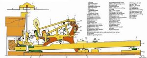
The given figure shows different parts of a piano mechanism. The hammer mechanism can be seen in the figure.

Piano Hammer
Parts of piano Credit: https://www.flickr.com/photos/rain0975/2509155870

Why is it good to make hammers out of high carbon steel?

Heat treated high carbon steel is used to make the hammer head.

The high carbon in steel provides high hardness and strength to the hammer. The heat treatment reduces the stress hence improve the fatigue strength. 

What is a hammer mill?

The hammer mill is mechanically powered hammer that is used in various industries.

Hammer mills are used for crushing large materials into small pieces by the continuous action of tiny hammers. The hammers are attached to a rotor, which rotates at high speed. A cylindrical drum covers the whole rotor hammer mechanism. The drum has two openings, the material to be crushed is inserted from the top, and the fine materials are taken from the bottom. The main application of hammer mills is crushing large rocks into small pieces, shredding automobile parts, etc.

What are mechanically powered hammers?

There are two types of hammers, mechanically powered and Hand powered.

The mechanically powered hammers are different from man-powered hammers.

The mechanically powered hammers use energy from a source other than manpower. The structure of a mechanical hammer is entirely different from the regular hammer; however, the working principle is the same. Examples of mechanically powered hammers are hammer drill, steam hammer, jack hammer, trip hammer, etc.

For more posts on Mechanical Engineering, please follow our Mechanical page.

Cam And Follower: 9 Interesting Facts To Know

weaving 2747847 960 720 300x200 1

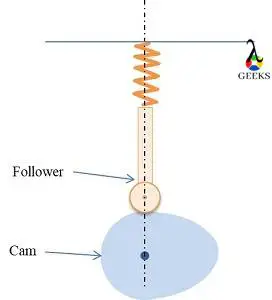
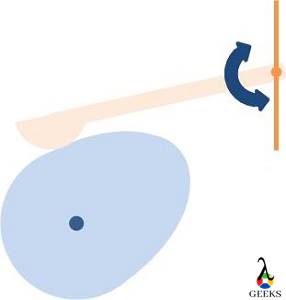
Cam and follower is a mechanism used to get the desired motion such as reciprocating or translational from an available input, usually rotational.

The cam and followers have numerous applications in industries and real life. Its application varies from simple child toys to high precision valve systems in IC engine. Here we are discussing about some of the examples of cam and follower.

We will discuss 10 cam and follower examples


Cam and follower in IC engine

Valves in IC Engine

There are two valves in a four-stroke IC engine. The suction valve and exhaust valve. Those valves have to be opened accurately for the better performance of the IC engine. The suction valve should open during air intake to the cylinder, and the exhaust valve should open to remove the combustion product. The accurate opening of these valves is operated by a cam and follower mechanism.


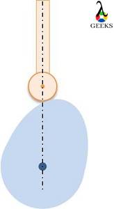
Generally, a radial plate cam with a flat-faced or spherical follower is used.


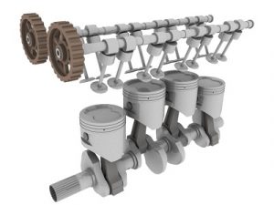
Generally, an engine consists of multiple cylinders; hence, each cylinder requires a cam mechanism. All the cams are located on a camshaft. The camshaft is linked with the crankshaft through a chain or belt drive or gear mechanism. Hence, the camshaft is driven by the engine itself.
The number of camshafts varies with the engine. The figure shows two camshafts, one for the exhaust valve and one for the suction valve.

Operation of the fuel pump in Diesel engine   

The fuel pumps are used in the Diesel engine. In a Diesel engine, the only air is added to the cylinder in the suction stroke; after compressing the air to high temperature and pressure, fuel is injected through a fuel pump. The fuel pumps are operated by a cam and follower mechanism similar to the valves.

Separate camshafts are provided for using the fuel pump in the engine.

Cam and follower examples
Cam and follower used in IC engines. The two cam shafts are visible in the figure.
Credit: https://commons.wikimedia.org/wiki/File:Engine_movingparts.jpg#filelinks

Cam and Follower in Industries

Cam automatic lathe

An automatic cam lathe is a machine in which the movements of tools are controlled by the cam and follower mechanism. This machine has high speed, high accuracy, and less noise.

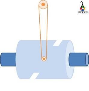
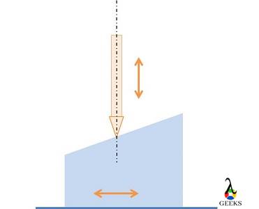
The tool has to move axially and radially; two cams are provided in automatic lathes; a cylindrical cam and a plate cam. The plate cam is used to provide the radial motion of the follower, and the cylindrical cam is used to provide the axial motion of the tool.

Cam indexer

The cam and follower are commonly used in the automatic manufacturing system. The application of cam is automatic indexing of the tool; hence the cam follower system is known as cam indexer. The primary purpose is the positioning of the tool.

The cylindrical cam or globoid cam with a rotating follower is used in cam indexing.

During the cam indexing period, the tool rotates and comes to the required location, then comes the dwelling period. The machining operation is carried out during the dwelling. The cycle is repeated.

The automatic screwdriver, rivets, etc., are some examples where cam indexers are used.

Weaving industry

Cam and follower are used extensively used in a weaving machine to get the shedding motion.

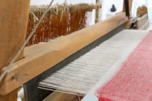
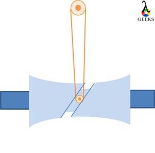
Shedding is the process of separating the warp yarns to make the space for passing the filling yarn. In weaving, one warp yarn is lifted above the other warp yarn, and the filling yarn is passed through the space; after this, the lifted warp yarn is returned, and the other warp yarn is lifted, and the filler yarn is passed through the space. The process is repeated. Hear, we can see the ascend, dwell, descend and dwell of the follower. There are two followers which are connected to the warp yarns. Hence, the conjugate cam and follower mechanism is used for this purpose.

weaving 2747847 960 720
Weaving operation. The white threads are warp and the pink is filler. We can see a space between the white threads through which the filler is passed in each weaving operation. Credit: https://www.piqsels.com/id/public-domain-photo-fedto

Paper cutting

There are mainly two motions in paper cutting. The transverse motion of paper that is to be cut and the motion of the tool. The tool is operated by a cam and follower mechanism. The tool is connected to the follower, and the tool reciprocates. When the tool is not cutting the paper, the paper makes the transverse motion using the Geneve mechanism.

Automatic copying machine

The cam and follower mechanism can be used to copy the surface profile of a component. Usually reciprocating cam is used for this purpose.

We need to copy the cam profile in this scenario. Hence the follower is mounted on the cam with a cutting tool on the other end. During the reciprocatin motion of the cam the follower cut the workpieces which is mounted on the other side of the follower. The workpiece profile will be same as that of the cam in the end of the cutting operation.

Cam and follower in real life

Wall clocks

The cam and follower mechanism are used in wall clocks. 

The heart shaped cam were used in early post office model clocks to synchronise the clock time with Greenwich Mean Time.

Toys

Different variety of toys can be made using cam and follower mechanisms. The mechanism can achieve the repeated motion in toys very easily.

Pin Tumbler Lock

Pin tumbler lock is special kind of lock where cam and follower mechanism is used to prevent the opening of the lock without the proper key.

Pin tumbler lock all
Working of pin tumbker lock. Credit: https://upload.wikimedia.org/wikipedia/commons/1/18/Pin_tumbler_lock-all.JPG

The figure shows the working of pin tumbler lock.

The first two figures shows the operation when the correct key is inserted. When we insert the correct key, the gap between driver pin(blue) and key pin (red) align with the edge of the plug (yellow), which allows the free rotation of the plug hence the lock can be opened.

When wrong key is inserted (left bottom figure), the key pin and driver pin gap will not along with the plug, hence it prevent the opening of the key.

The last figure (bottom right) shows the position of key pin and driver pin when key is not inserted.

FAQ

Why cam and follower are used?

Cam and follower mechanism is extensively used in ic engine, industries and in real life.

It is a simple, compact mechanism that can work with high accuracy, and a large variety of motions can be generated by the proper design of cam profile.

What are the applications of cam and follower?

There is a variety of applications for cam and follower. Some are listed below.

  • The valves of IC engines are operated by cam and follower
  • Conjugate cam is used in the weaving industry for getting shedding motion
  • A large variety of toys uses a cam and follower mechanism.
  • Cam and follower are used in automatic lathe machines.
  • Cam mechanism used for tool indexing
  • Cam and follower are used in paper cutting machines.
  • Cam and followers are used in conveyor belts.

What is the material used for making camshafts?

Chilled cast iron is used for making the cam shafts.

What is the application of cam and follower in the weaving industry?

In the weaving industry cam and followers are used to get the desired motion in the process known as shedding.Shedding is the process of separating the warp yarns to make the space for passing the filling yarn. The conjugate cam follower mechanism is used.

Two concentric cams are connected on a shaft in the conjugate cam and follower mechanism, separate followers attached to each cam. The unit rotates together, and the follower rise or falls accordingly.

What are the application of cam and follower in automobiles?

The main applications of cam and follower in automobiles are given below,

Magneto Ignition System: 11 Important Facts

Magneto Ignition System edited 300x225 1

Have you wondered what happens to petrol when it reaches the fuel tank? Well the answer is simple, the fuel is ignited to produce a certain amount of thermal energy which then gets converted into mechanical energy (rotary motion of wheels). 

There are two ways by which fuel can be ignited- with the help of electric spark or by applying high pressure. Now the question arises, how to create a spark inside the engine? This is the situation where magneto ignition system comes into play.

In spark ignition engines (petrol engines), a spark is required to ignite the fuel. The source of electricity to create a spark may vary according to engine requirements. Read this article further to get a deep insight on how does a magneto work.

What is magneto ignition system?

Spark ignition engines create a spark to ignite air-fuel mixture. This spark is created with the help of an ignition engine.


An ignition system that uses a rotating magnet (magneto) for generating electricity is known as magneto ignition system. This electricity is used to power spark plugs.

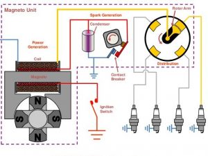
Magneto ignition system diagram

How does magneto work
Image: Magneto ignition system
Image source

Parts of magneto ignition system

Magneto ignition system uses following parts-

Many parts are employed which work in harmony to give desired output. The basic parts of magneto are discussed below-

  • Magneto
    Magneto refers to a group of rotating magnets used for producing high voltage. The rotational speed of engine (rpm) is directly proportional to the voltage produced by rotating magnets. Based on the rotation of parts, magneto is of three types-  

    -Armature rotating type
    -Magnet rotating type
    -Polar inductor type
  • Distributor
    As the name suggests, distributor invites ignition surges and then distributes it among individual spark plugs. Distributor has a rotor in the center and metallic electrode on the periphery.
  • Primary and secondary winding
    Primary winding act as the input that is draws the power from source and secondary winding having more number of turns acts as output. Secondary winding is connected to distributor.
  • Cam
    Cam facilitates the motion of magnet. It is connected to the poles of magnet.
  • Circuit breaker
    Cam motion is designed in such a way that it breaks the circuit at certain intervals. When the circuit is breaks, the capacitor starts charging by primary current.
  • Capacitor
    A capacitor is an assembly of two metallic plates placed at a small distance from each other.  Capacitor stores charge.
  • Spark plug
    Spark plug is used for igniting air-fuel mixture inside the engine cylinder. Spark plug has two metallic electrodes separated by a small distance.

How does a magneto work?

Magneto system employs a rotating magnet as the source of electricity, rest of the working is similar to the battery ignition system. Working of magneto ignition system is explained briefly below-


As the engine rotates magnet inside the coil, an EMF is generated and so a current starts flowing through the coils. As the poles of magnet start moving away from the coil, the magnetic flux begins to decrease. At this point, the cam breaks the circuit (cam-type contact breaker).

As the contact breaker breaks the circuit, the flow of current disrupts. As a result, capacitor starts charging and voltage on the secondary winding increases rapidly. The voltage increases up to such an extent that it is able to jump small gaps. When this happens, spark is created and fuel-air mixture is ignited.

Types of magneto ignition systems

Based on the engine rotation, magneto ignition system can be of following type-

  • Magnet rotating type- In this type, magnet rotates and armature is kept fixed. As a result there is a relative motion between magnet and the windings. In modern days, this type of magneto ignition system is commonly used.
  • Polar inductor type- In this type, both the coil and magnet is kept fixed. The moving part here is a soft iron core having projections at fixed intervals.
  • Armature rotating type- In this type, magnet is fixed and the armature rotates.

Dual magneto ignition system

Usually a single magnet is used in small engines like in that of two wheelers. Big engines like that of aircrafts need an extra magnet for safety. In dual magneto ignition system, two magnets are used instead of one. This increases the safety factor of the engine.

Dual magneto ignition system is used in aircraft engines where each engine cylinder has two spark plugs and each spark plug is fired by its individual magneto. In case where failure of one magneto takes place, other magneto keeps the engine running with a slight decrease in efficiency.

High tension magneto| Low tension magneto

There are two types of magneto- high tension and low tension magneto. Their working principle being same in ignition system. Both of these magnetos have a minute difference between them.

High tension magneto produces pulses of high voltage that are sufficient enough to jump across the length between two electrodes of spark plug. This type of magneto works when the circuit breaks, only then the voltage rises up to desired level. The main disadvantage of this type of magneto is that it deals with very high voltage.

Low tension magneto produces a low voltage that is distributed in the transformer coil which is again connected to spark plug. Using a low tension magneto eliminates the need of dealing with high voltages. This type of magneto is generally used in spark ignitors and not in spark plugs.

Battery ignition system| Difference between battery and magneto ignition system

Battery ignition system serves the same purpose as magneto ignition system. It acts as the source of electricity that is used to produce sparks in spark plug.  

Battery ignition system was commonly used in four wheelers but now it is being used in two wheelers as well. A 6V or 12V battery is used to produce a spark unlike magneto ignition system where magneto was the source of electricity.

Battery takes more space hence it was not suggested to use it in two wheelers where space constraint is more. Nowadays compact battery systems are available that can be used in two wheelers also.

The major difference between a battery and magneto ignition system is the source of electricity. In battery ignition system, as the name suggests, battery is used as the source of electricity whereas magneto ignition systems use magneto for generating electricity.

Electronic ignition systems

Electronic ignition systems use electrical circuits having transistors that are controlled by sensors to produce spark. This type of system can ignite even a lean mixture and provides better economy.

Electronic system is divided into two types- Transistor and distributorless ignition system. Electronic ignition system in general, doesn’t use breaker points like those used in magneto ignition system. Hence, this type of system provides breakerless ignition.

Advantages and disadvantages of magneto ignition system

Not every system is ideal, every system has its own pros and cons. It is a design trade off which decides which type of system needs to be used. Following are the advantages of magneto ignition system-

  • It generates electricity on its own hence no need of battery.
  • It occupies less space.
  • No problem of charging or discharging of battery as it doesn’t use one.
  • High efficiency/reliability due to high voltage spark.

Disadvantages of magneto ignition system are-

  • Costlier than other ignition systems.
  • During start, quality of spark is low due to low engine speed. It gets higher with high engine speed.

Practice questions

How does a magneto ignition system work?

Ans: Magneto ignition system works on the principle of Faraday’s first law of electromagnetic induction.

The relative motion between magnet and transformer coils induce an electromotive force (EMF). Due to this, a varying electric current is produced. As rotation of the magnet progresses and poles start moving farther from the coil, a circuit breaker breaks the circuit and disrupts the flow of current.

Due to this, a high voltage is produced at secondary coil which is then distributed to the spark plugs. The voltage is high enough for it to jump across the length between two electrodes of spark plug.

What are the main advantages and disadvantages of magneto ignition system?

Ans: The magneto ignition system has its own pros and cons. Advantages of magneto ignition system are as follows-

  • No batteries are requires as magneto itself generates electricity.
  • Takes up less space than other ignition systems.
  • No problem of discharge as no batteries are used.

The following are disadvantages of magneto ignition system-

  • Expensive as compared to other ignition systems.
  • The voltage produced is directly proportional to the engine speed. So low voltage is produced at start due to low engine speed.

What are the three types of ignition systems?

Ans: To ignite the air-fuel mixture, an ignition system is required. For industrial applications, three types of ignition systems are commonly used-

  • Battery ignition system
  • Magneto ignition system
  • Electronic ignition system

What is the purpose of magneto in an ignition system?

Ans: Magneto is a rotating magnet whose rotation speed is equal to the engine speed.
        
      Pulses of high voltage are required to produce a spark in spark plugs. These pulses are produced by a magneto. The spark produced ignites the air-fuel mixture.

Why magneto ignition system is not used however it has higher efficiency and low maintenance?

Ans:  Magneto system works solely on mechanics of engine rotation hence the voltage keeps varying at different speeds. Electronic ignition system is more efficient overall as it can also ignite lean air-fuel mixture. With use of transistors and sensors, the precision of producing sparks improved. Also, mechanical components are ought to wear after certain period of time.

Because of above reasons, magneto systems are not used these days. However, they were best suitable at the time of their invention.

What route is followed by current in magneto ignition system?

Ans: Current in magneto ignition system is induced by varying magnetic flux around the coil.

The induced current flows through primary winding. A circuit breaker breaks the circuit at certain intervals. Current flow disrupts when the circuit is broken. This results in increase of voltage at secondary winding which is connected to spark plug. As the poles reverse, the flow of current reverses.

What is a more efficient ignition system coil and battery or magneto?

Ans: The answer to this question depends on the basis of comparison.

        If we compare on the basis of space and discharge rate, then magneto is more efficient as it takes up less space and has no issue of discharging.

       If we compare on the basis of ignition timing, then battery ignition system is more efficient as it doesn’t have fixed ignition timing. Magneto ignition system is designed mechanically so, it has a fixed ignition timing.

This becomes a problem at low speeds because of low voltage produced. Hence, an ignition system with variable ignition timing is more efficient than one with fixed ignition timing.

Cam and Follower: Definition, Types, Working Principle, Advantages, Applications

Diagram Low 2

Table of Content

Cam and follower

Cam and follower is a mechanism used to get the desired motion such as reciprocating or translational from an available input, usually rotational.

Cam and follower with different size and shape are available in the market.

The elements of the mechanism are;

  • Cam
  • Follower

Diagram of cam and follower

Cam and follower

What is a Cam?

Cam is the driving component in the mechanism, making sure that the follower follows the desired motion.

Hence, the profile and size of the cam are significant in a cam and follower mechanism.

While designing the mechanism, the main concern goes to getting the appropriate profile of the cam.

What is a follower?

The component which gives the desired motion in the mechanism is the follower. The motion of the follower is the output in the cam follower mechanism.

Generally, followers are having two distinct types of motions, oscillating and reciprocating. The followers are designed in such a way that, it always touches the cam during the cam operation.

As the follower moves over the cam, there is friction resistance and side thrust acting. The friction resistance leads to the wear failure of the cam follower mechanism.

Classification of cam and follower | Different types of cam and follower

There are different types of cams and followers available according to the applications.

Those are discussed below;

Types of Cams

The cams can be classified as follows;

Cam Working Low 2

Types of cams : based on the shape

  • Plate or disk cam

It is the most commonly used cam. It is cut from a metal disk or plate to a pre-planned shape according to the requirement.

Many important cam parameters can be explained using the plate cam, like the base circle, pressure angle, pitch point, etc.

.

Cylindrical follower low 6
  • Cylindrical cam

The cam is of cylindrical shape. A groove is cut on the surface of the cylinder and follower moves inside the groove. The cylinder rotates, and the follower oscillates accordingly.

Cylondrical Cam Low 3
  • Wedge cam

The figure shows a wedge cam. Wedge cams have a wedge of specified shape that reciprocates and leads to reciprocation or oscillation of the follower.

Wedge Cam low 3
  • Spherical cam

A spherical cam is similar to a cylindrical cam; the only difference is groove is cut on a sphere instead of a cylinder.

  • Globoid cam

Globoid cam is also similar to cylindrical cam; the only difference is grove is cut on a globoid shape.

Globoidal Cam Low 3
  • Conjugate or dual cam

The conjugate cam consists of two-disc cams that are bolted together. This type is used for very quiet operations.

Types of cams : based on follower movement

The follower movement can be classified as,

  • Dwell – No movement to the follower.
  • Rise or Ascend – The follower moves upward.
  • Return or Descent – The follower moves downward.

The cam profile controls the length and amount of ascend, descend or dwell in a cam follower mechanism. Hence, according to the follower movement, cams can be classified.

By proper design of cam profile, any combination dwell, rise or return can achieve. In each cycle, the follower comebacks to the initial state. Hence, if there is a ascend, then the equal amount of descent will be there in the cam profile automatically.

Some combinations are,

  • Rise, Dwell, Return cam
  • Rise, Return, Rise cam
  • Dwell, Rise, Dwell, Return, Dwell cam

Types of cams : based on the type of constraint

  • Spring-loaded: The contact between cam and follower is enabled using a pre-loaded spring.
Spring Cam low 2
  • Positive drive: Providing groove as shown in cylindrical cam is an example of a positive drive cam. Here, the follower motion is constrained due to the presence of groove.
  • Gravity cam: The gravity force helps to keep the contact between cam and follower. The follower weight should be sufficient in order to get constant contact.
Springless Low 2

Types of Followers

The followers can be classified as follows;

Follower Types Low 3

Types of Followers : Based on the shape of the follower

  • Knife edged follower

An example of a knife-edge follower is given in the figure. It is having a sharp edge, i.e., knife edge, making contact with the cam.

We can expect a higher frictional resistance and wear for these types of cams. And the system has considerable side thrust also. Due to these limitations, it is not commonly used.

Knife edge follower Low 2
  • Roller follower

In this follower, the pointed edge is replaced with a roller that freely rotates about its axis. Here, the frictional resistance and wear are reduced. However, the side thrust is not eliminated.

Cylindrical follower low 7
  • Flat-faced follower

It is also called a Mushroom follower. The point contact in the knife-edge follower is replaced with a flat plate, as shown in the figure. Here, the frictional resistance is not reduced; however, a considerable decrease in side thrust can be achieved.

The cam profile should have a convex shape for this type of follower; otherwise, the follower and cam get stuck in the concave profile of the cam.

FlatFaced Followe Low 2
  • Spherical faced follower

This is similar to flat-faced follower; the difference is that the contacting profile has the shape of a hemisphere; hence the frictional resistance also reduces.

Spherical follower Low 2

Types of Followers : Based on the motion

  • Oscillating follower

The follower oscillates in this type of cam follower mechanism. An example is given in the figure.

Oscilating Low 3
  • Reciprocating follower

The follower reciprocates in this type of cam follower mechanism. An example is given in the figure.

Reciprocating low 2

Types of Followers : Based on the path of the follower

  • Radial or in-line follower

In this type of followers, the cam center and line of action of the follower are in same line as shown in figure.

Cylindrical follower low 8
  • Offset follower or Eccintric cam follower mechanism

In this type of followers, extended line of action of follower and cam center does not lie in the same line. The side thrust is reduced if we are using an offset follower.

Offset Low 2

The Terminology of a Cam

We already discussed the importance of a cam profile.

Now we will be looking into some important terminology of the cam.

The figure shows a cam with a roller follower, indicating all the terms we are about to discuss.

Cam Terminology Low 2

The roller at the different positions over the cam is shown, assuming the cam remains stationary and the roller travel along with the cam profile.

  • Base Circle 

It is the smallest circle drawn with center on the cam center and touches the cam profile.

  • Trace points

These are the arbitrary points around the cam profile, through which the center of the follower moves.

In the case of roller follower, trace points are obtained by adding the radius of the roller from the cam profile, as shown in the figure.

For knife-edge followers, the trace points are on the cam profile itself.

  • Pitch curve

If we join all the trace point we get the pitch curve.

  • Prime circle

It is the smallest circle drawn with center on the cam center and touches the pitch curve.

  • Pressure angle

Pressure angle is defined in every point in pitch curve.

It is the angle between direction of the follower movement and the normal to the pitch curve.

Higher the steepness in the cam profile, the higher the pressure angle.

Higher pressure angle is not preferred as it increases the force required to lift the follower.

  • Pitch point

It is a point in the pitch curve where the pressure angle is maximum.

  • Pitch circle

Circle with center on cam center and passes through the pitch point.

Working mechanism of cam and follower

The figure shows the cam and follower mechanism at different positions.

Cam Working 2

In the given figure, the cam rotates in an anticlockwise direction.

Initially, for some duration, the follower moves upward. The upward movement is known as the ascend or rise period (between (a) and (b)).

After that, the follower stays in the same position for some rotation of cam (between (b) and (c)).

Hereafter, the follower moves downward (between (c) and (d)), known as descend or return. At the end of the return, the follower reaches its initial position and remains stationary until the next cycle starts (between (d) and (e)).

The cycle keeps on repeating. Here, we got the reciprocating motion for the follower from the rotational movement of the cam.

The motion of the follower can be categorized as rise-dwell-return-dwell.

We can change the motion of the follower by appropriately designing the cam profile.

Imagine the follower motion for figure given below,

Special CAM Low 2

Forces acting in a cam and follower mechanism

There are mainly two forces acting in cam follower mechanism, normal force and frictional force.

Force Low 2

The direction of normal force and frictional force is shown in the figure. The normal force acts normal to the cam profile, and the frictional force acts tangential to the cam profile.

The normal force can split into two components; horizontal and vertical.

The equation for horizontal and vertical force are given below,

F_v = F_ncostheta

F_h = F_nsintheta

The vertical force is helping to lift the follower. The horizontal force is an unnecessary force, which gives a side thrust to the follower.

The angel θ is the pressure angle.

The above analysis is carried out only for normal force. The frictional force also can be analysed similarly by splitting it into horizontal and vertical components.

It can be observed that the friction force increases the side thrust and decrease the net lift force.

Side thrust in cam and follower

As explained above, the side thrust is an unnecessary force that should be reduced for the smooth operation of the cam and follower mechanism.

One component of normal force and frictional force is contributing to the side thrust.

The side thrust can be reduced by,

  • Using a flat face follower
  • Using offset cam follower mechanism.
  • Reducing the pressure angle.
  • Reducing the friction

Significance of pressure angle in cam and follower

From the above analysis, we can see that the increase in pressure angle leads to a decrease in the lift force and an increase in the thrust force. The lift force must be sufficient to overcome the spring force or gravitational force in the cam follower mechanism. Hence, if the pressure angle is very high, high energy is required to lift the follower.

Therefore, the pressure angle is usually kept as low as possible in the cam follower mechanism.

Cam follower design

Now, we discuss how to design a cam follower mechanism.

The design of cam profile is the primary step in manufacturing of the cam follower mechanism.

The cam profile depends on the size of the follower, type of follower, and the kind of motion required.

Constant velocity, constant acceleration and simple harmonic motion are some of the motions in cam and follower mechanism.

The cam profiles are different for getting the above motions.

Before discussing the cam profile, we should know about some terms.

Angle of ascend : The angular rotation of the cam during the ascend of follower is known as angle of ascend.

Angle of dwell: It is the angular rotation of the cam during the dwell period.

Angle of descend: It is the angular rotation of the cam during the return period.

Lift or stroke: The distance travelled by the follower during the rise or return period.

Now, let’s discuss designing a cam profile.

The critical step in designing the cam profile is drawing a displacement diagram.

The displacement diagram is the graph plotted between the angular distance of the cam and the lift of the follower.

The displacement diagram varies for different motions.

After getting the displacement diagram, we have to transfer the distance to the base circle to get the cam profile.

Displacement diagram

The displacement diagram for different motions is explained in this section.

The angle of ascend, dwell, descend, and lift of stroke are predefined variables.

Now let’s assume that the angle of ascend, dwell, and descend, and lift of stroke are 90o, 90o, 90o, and 10cm, respectively.

Drawing different displacement diagrams are explained below;

Constant velocity

  • Draw x axis and y axis, mark the angles in x axis and lift in y axis.
  • Mark the ascend, descent, and dwell in x axis.
  • Join the left bottom corner and right top corner in ascend to get the displacement of follower during the rice period.
  • During the dwell period, the displacement curve will be parallel to the x-axis.
  • Join the left top corner and bottom right corner for drawing the displacement curve during the descend.
Constant Velocity Low 2

Constant acceleration

The figure shows drawing the displacement diagram for ascend.

constant accelaration Low 3
  • Divide the angle of ascend to even number of parts (n parts). And draw vertical lines.
  • Mark the center line and divide it into n parts.
  • Draw a line from the bottom left corner to each point in the centerline till n/2 parts, do the same for the remaining point from the top right corner.
  • Mark point of contact between 1st vertical line and 1st inclined line and 2nd vertical and 2nd inclined line and so on.
  • Join the points.

Simple harmonic motion

The figure shows drawing the displacement diagram for ascend.

Simple Harmonic Low 2
  • Divide the angle of ascend to n number of parts. And draw vertical lines.
  • Draw a semi-circle in the y axis with diameter equals to lift, divide it into n parts.
  • Now, draw a horizontal line from each point on the semi-circle to the corresponding vertical lines.
  • Joint the point of contact between the horizontal line and vertical line.

Drawing cam profile

The figure shows the cam profile for the constant velocity profile mentioned above.

The steps involved in drawing cam profile from displacement diagram are,

  • Draw the base circle.
  • Mark ascend, descend and dwell period in the base circle.
  • Divide ascend, and descend to equal parts similar to displacement diagram.
  • Measure the distance from the x-axis to the curve in displacement diagram for each vertical level.
  • Mark the measured distance from the base circle for each vertical level, respectively.
  • Join the pints
Cam profile Low 2

Cam and follower material selection

For most applications, the cam is manufactured using metals. Steel alloys and cast irons are most commonly used material.

The thermoplastic like nylon and polypropylene are used in some cases.

How to build a cam and follower?

Here we discuss the manufacturing technique used for producing cam and follower.

Initially, we have to design the cam and follower and study the forces acting, stress-induced, the maximum load the cam follower pair can handle, etc. Generally, SolidWorks software is used to design the cam and follower mechanism.

For thermoplastic materials, impact molding is used for manufacturing.

For metal cams variety of manufacturing techniques is used. Conventional manufacturing techniques like grinding, milling, cold forging, etc., are used to produce cam. For high accuracy, CNC machining is used. Powder metallurgical techniques are also used in many situations.

Degree of freedom of cam and follower

The degree of freedom of cam and follower should always be one.

The degree of freedom indicates the number of independent variables to define the motion of the system. Degree of freedom 1 means we need one independent variable to describe the motion. That means the movement between the links is only possible in one way. If we rotate the cam, the follower will only reciprocate; it will not reciprocate and oscillate together.

The constraints are provided to make sure that the degree of freedom of the system is one.

Applications of Cam and Follower

  • IC engines
    • Opening and closing of inlet and exhaust valve.
    • Operating fuel pump
  • Automatic lathe
    • feed mechanism
  • Toys
  • Wall clocks

Cam and follower advantages and disadvantages

Advantages of cam follower mechanism

  • By proper designing of cam profile, a variety of follower motions can be obtained.
  • Able to operate accurately.
  • Easy mechanism to convert the rotational motion to reciprocating or oscillating motion.
  • The number of components reduces with the use of a cam and follower mechanism.
  • Compact

Disadvantages of cam follower mechanism

  • Subjected to wear, hence, can be used only when the transmission force is less.
  • Accurate manufacturing is required.
  • High manufacturing cost.
  • There is a limitation to the size of the mechanism. Large size is challenging to operate.

Cam and follower objective questions

  1. During the rise or ascend period, the follower is;
    1. Moving up
    2. Moving down
    3. Stationary
    4. None of the above

Ans: 1

  1. In cam and follower, friction should be
    1. High
    2. Low
    3. Medium

Ans: 2

  1. The side thrust can be reduced if we use;
    1. Roller follower
    2. Knife edge follower
    3. Flat plate follower

Ans: 3

Cam and follower problem

Try to answer the given problem yourself,

  • Draw displacement diagram and cam profile for following conditions,

Follower Type: Knife-edge follower

Lift : 6 cm

Base circle radius: 6 cm

Angle of ascend: 60

Angle of dwell: 120

Angle of descend: 60

Motion type during ascend: Simple harmonic motion.

Motion type during descend: Simple harmonic motion.

Important Questions and Answer 

What is the difference between cam and follower?

Cam is the driver in the cam and follower mechanism, which reciprocates or rotates. The follower is the driven component, which oscillates or reciprocates. The ultimate aim of the cam and follower mechanism is to get the desired motion for the follower.

Cam and follower motion?

The cam and follower can have a different combination of motions.

The cam usually rotates(cylindrical, plate cams) or reciprocate (wedge cam)

The follower oscillates or reciprocate.

Is a cam follower a lifter?

Yes

Cam and follower types

A detailed description is given in the above content.

Why are ‘offsets’ required in cam and followers?

The offset is used to reduce the wear and side thrust.

In physics mechanics, how come a cam follower is a higher pair?

The classification of higher pair and lower pair is based on the contact between the links. The nature of contact is point (knife-edge follower) or line (roller follower) in the cam follower mechanism. Hence it is higher pair.

What is the significance of pressure angle in Cam followers?

The pressure angle indicates the steepness of the cam profile.

An increase in pressure angle leads to a decrease in the lift force and an increase in the thrust force. The lift force must be sufficient to overcome the spring force or gravitational force in the cam follower mechanism. Hence, if the pressure angle is very high, high energy is required to lift the follower.

Therefore, the pressure angle is usually kept as low as possible in the cam follower mechanism.

Why is the roller follower preferred over the knife-edge follower?

The roller follower is preferred over the knife-edge follower to reduce the friction, hence the wear of the follower.

What is the pressure angle and methods to control the pressure angle of a cam?

Pressure angle is defined at every point in the pitch curve.

It is the angle between the direction of the follower movement and the normal pitch curve.

Methods to reduce pressure angle;

  • Use offset follower
  • Increase the size of cam
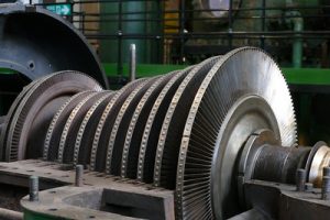
AFBC boiler: 17 Answers You Should Know

Somketube fbc 300x226 1

afbc boiler flow diagram | afbc boiler diagram
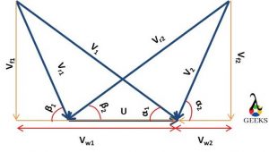
afbc boiler
Schematic diagram of FBC boiler credit Wikipedia

advantages of cfbc boiler over afbc boiler | difference between afbc and cfbc boiler

AFBC means atmospheric – fluidized – bed – combustion. The speciality in this boiler is to keep furnace pressure at atmospheric conditions. The burnt gases developed in the combustion chamber are passes through the cyclone and are discharged into the atmosphere.

CFBC means circulating – fluidized – bed – combustion. In this kind of boiler, the furnace gas is pressurized to recirculate in the chamber. This recirculation of gases captures the unburnt carbon. Thus, the thermal efficiency of a boiler is increasing because of gas recirculation.

The comparison of the AFBC and CFBC boiler can be made based on the following parameters and criteria.

The velocity of the gases

In AFBC, It is around the 1.2 – 3.7 m/s

In CFBC, It is around 3.7 – 9 m/s

Heat Transfer Surface

In AFBC, The heat extraction can be done from bed only

In CFBC, The heat transfer was carried out bed and other surfaces of combustion chamber. It is known as the convective zone. The heat transfer from water walls is possible.

Fuel size

Coal is a widely used fuel in both boilers, but the size of coal particles in CFBC is 2-3 mm more.

Supply of air in combustion chamber

In AFBC boiler , The range  is  3 to 5 PSI gauge

In CFBC boiler, The range  1.5 to 2 PSI gauge

From above comparison we can say that the Performance characteristics of the CFBC boiler are better than the AFBC. It is an advanced technology of circulating gases. It is developed to solve some difficulties that arise in the AFBC. Some of them are discussed as below,

  • 1. The utilization space in the CFBC boiler is adequate than AFBC.
  • 2. The combustion of fuel is efficient more in the CFBC boiler.
  • 3. SO2 and NOx can be controlled more in the CFBC boiler.
  • 4. The control of temperature is more in the CFBC boiler.
  • 5. It can work effectively even with the low calorific value of the fuel.
  • 6. the turndown ratio is higher
  • 7. Both over & under feed systems can be used

afbc boiler working principle | afbc boiler start-up procedure

  • Following are the steps to be followed to start the afbc boiler
  • The air nozzles are cleaned by entering the full Fd air into the combustion furnace. Open the air compartment door for 10 to 15 minutes to complete this task
  • Enter the bed material into the combustion furnace. The bed height is to be around 250 to 300 mm above the nozzles.
  • The material below the nozzle is to be a static fix. It is also considered in the bed height
  • Enter the fluidizing air through the complete bed to uniformly distribute the bed materials over the bed. The PA damper is kept close during this operation
  • Open the startup compartment when you feel the uniformity in bed material and bed height.
  • Now increase the flow of air to develop tiny bubbles all over the bed material. This stage is called the bubbling stage. Read the airflow rate and note it down at this stage.
  • In the next step, Increase the furthermore the flow of air to make the bed turbulent. It is helpful for proper mixing of the upper and lower layer of the bed material. This is called the mixing stage. Read the airflow reading at this stage.
  • Switch off the fan and airflow rate. Now boiler is ready to start
  • The drum is level is to be maintained at around 40 %
  • Initiate firing
  • Keep initializing for few minutes, start All three fans as per sequence (ID, FD and PA)

afbc boiler design | accepted range of afbc boilers

The construction and working of AFBC with an explanation of various parts involved,

Main systems in the AFBC

  • Fuel supply system
  • Air Distribution
  • Heat transfer in Bed and surface
  • Ash Control system

Generally, these four main systems are included in every FBC boiler.

1. Fuel Supply System

There are two types of fuel supply systems in FBC boilers. Under-bed pneumatic supply and over bed supply.

The absorbent is used for fuel supply—examples: dolomite, limestone etc.

In under bed pneumatic supply, the coal is crushed and pulverized in 1 to 6 mm in size. This coal is supplied from the inlet hopper to the combustion chamber with the pneumatic arrangement. This system is developed according to capacity.

2. Air distribution system

The air distributor is the main component of any FBC boiler. It is utilized to pass or distribute the fluidized air from the furnace bed. The air distributor is keeping the solid particle motion at a constant rate. The air distributor is made from a metallic plate. The pattern geometry is made with the perforation in it. The nozzles are installed with perforation in it. This perforation is not allowing the solid particles to go back into space.

There are some arrangements made to protect the distributor from the temperature of the bed.

i) Refractory material Lining brick

ii) Fix layer of the materials in bed

iii Cooling tubes

3. heat transfer in bed and other surfaces

a)  heat transfer in Bed

The bed is made with particular kinds of materials like crushed limestone, refractory, ash and sand. The size of material particles is around 1 mm. There are two types of bed widely used beds in the FBC boilers.

(1) Shallow bed

(2) Deep bed

(1) Shallow bed

The power consumption of the fan is low in the shallow bed. In addition, the resistance of the bed is less in shallow beds, so the pressure drop is also lower.

(2) Deep bed

The power consumption of the fan is high in the deep bed. The resistance of the bed is more in a deep bed. The gas velocity is raising because of  pressure drop.

b)  Heat Transfer on surface

In the FBC boiler, the heat transfer should be sufficient within the bed material and the bundle of the tube or coils. The heat transfer is more superior in the horizontal orientation of the heat exchanger in shallow bed air distribution. There are few  parameters on which the heat transfer is depending,

Temperature of bed

Solid fuel particle size

Design and the layout of heat exchanger

Structure of the air distributor

Velocity of gas

4. Ash Handling System

a) Bottom Ash drain

There are two types of ash present in the FBC boiler. One is the fly ash, and the other is the bottom ash. Generally, the sediment ash is nearby 30 to 40 %. This ash is taken out when exceed limit to control bed height.

b) Removal of fly ash

The fly ash of the FBC boiler is more than other boilers. The combustion efficiency can be increased by utilizing the fly ash in some units. It is happening because the speed of the particle is very high. The fly ash travels with the flue gases, which is taken out at various stages from the FBC unit. There are three stages for the removal of the fly ash. (1) Convection part of FBC (2) Before air preheater or economizer (3) dust collector

There are many types of dust collectors available in the FBC boilers. (1) Cyclone (2) electrostatic precipitator (3) bagfiler (4) Combination of dust collectors

afbc boiler bed height calculation | afbc boiler bed height

The height of bed is calculated with the following equation in boiler,

level  of bed = Pressure in wind box – Differential pressure in the bed nozzles

DP test in afbc boiler | dp test procedure for afbc boiler

  • The first step is to precheck the bed with the following steps:
  • Make bed properly clean
  • Complete the maintenance of air nozzle and bed
  • The FD fan should work with higher efficiency
  • Steps of Procedure for DP test:
  • Initially start the ID fan, Start FD fan with minimum speed
  • Keep Air preheater inline
  • Raise the speed of airflow (Increase from 25% – 100%)
  • Read and note the pressure in the wind box at every stage
  • For all other compartments, repeat the same procedure
  • The value of pressure in the wind box needs to be nearby with designed values
  • Interpretation of DP test
  • The nozzle, bed plates are in good condition if the value of wind box pressure is nearby the designed value
  • The nozzles may be blocked if the value of wind box pressure is exceeded the design value
  • The nozzles may be damaged or defected hole if the value of wind box pressure is less than the design value

bed material size for afbc boiler |  afbc boiler bed coil

In the AFBC boiler, there are many grades of solid fuel (coal) available. The size of the coal particle is varied from 1 -10 mm. The size of coal particle is chosen based on the type of coal, quality of coal etc. The atmospheric air is used for two purposes, fluidizing air and air for combustion. First, this air is provided with sufficient pressure over the bed. Second, this is preheated by an air preheater in the boiler.

The velocity of this fluidizing air can be in the range of 1.2 – 3.7 m/s in the AFBC boiler. The flow rate of air passes through the bed can be utilized to determine fuel reaction. The bed temperature can be maintained by installing the bed evaporator tube to construct a limestone or sand bed. The bed evaporator tube helps reject the heat from the bed to maintain the temperature of the bed.

The bed is made up of depth  0.9 m to 1.5 m. the pressure drop across the bed is expected around 1 Inch per inch of depth of the bed.

The generated flue gases from the FBC combustion chamber is passed through the superheater section, economizer and air preheater. After air preheaters, the flue gases are exhausted from the atmosphere.

The AFBC boiler is famous for its temperature range. The temperature range of the AFBC boiler is 800 °C to 950 ° C. If the temperature exceeds this range, the boiler’s performance is decreased.

afbc boiler air nozzle

Two types of nozzles are widely used in the AFBC boiler.

Fluidizing nozzle:

This type of nozzle is made up of the S S or alloy steel. It is fitted on the bedplate. The hole size is about 2 – 5 mm. The air of the FD fan is entering from the wind box to the combustion furnace.

Coal feed Nozzle:

This nozzle is used to enter coal with air into the combustion furnace. The total number of nozzle is taken according to the size and capacity of the boiler. It may be 4 -6 nozzles. It is also fitted on the bedplate.

afbc boiler bed material density

The material density of the bed is around 1100 kg/m3

afbc boiler efficiency | afbc boiler efficiency increase

The combustion efficiency is depending on the following parameters :

(1) Reaction properties of fuel

(2) Volatility of fuel

(3) Size of the fuel particle

Coals like sub-bituminous or lignite are highly efficient in burning. There is no fly ash recycling or under a bed; feeding requires if the coal quality is good. The combustion efficiency of the AFBC boiler is in order of 70 to 99 %. The combustion efficiency is decreased. The efficiency of the AFBC boiler can be achieved by system improvement. The coal-like anthracite burns with low efficiency in the AFBC boiler. It can burn with higher efficiency in the CFBC boiler with the applications of fly ash recycling and the under bed feeding.

afbc standard boiler parameters

The following are the standard parameters which the of the AFBC

  • Size of the coal particles
  • Specification and size of the bed material
  • Air pressure from the FD fan
  • Height of the bed
  • Temperature of furnace
  • The temperature of the bed

afbc boiler velocity of flue gas | flue gas velocity in afbc boiler

The velocity of this fluidizing air can be in the range of 1.2 – 3.7 m/s in AFBC boiler.

afbc boiler interview questions and answers

What steps will you follow if the temperature of the bed increases?

The following are the points to be considered if the temperature of the bed is raising,

  • Load reduction
  • Maintain the density of the coal
  • Increase the material of the bed

What are the probable facts for the decrement in bed temperature?

  • The following are the probable facts for the decrement in the bed temperature,
  • The quality of material used in bed is poor
  • Suddenly action of the boiler load reduction
  • Excessive air entered the furnace
  • Fuel contains moisture

What is the reason behind the use of lime in the AFBC?

The coal contains some moisture, which has to be removed before combustion for better combustion efficiency. The purpose using lime is to absorb and remove the moisture from the fuel.

Which one is superior CFBC or AFBC ? Explain why?

We can conclude that the Performance of the CFBC is more superior to the AFBC. It is an advanced technology of circulating gases. It is developed to solve some difficulties that arise in the AFBC. Some of them are discussed as below,

1. The utilization space in the CFBC boiler is adequate than AFBC.

2. The combustion of fuel is efficient more in the CFBC boiler.

3. SO2 and NOx can be controlled more in the CFBC boiler.

4. The control of temperature is more in the CFBC boiler.

5. It can work effectively even with the low calorific value of the fuel.

6. the turndown ratio is higher

7. Both over & under feed systems can be used

For more Articles related to Boiler Please click here