Common Bolt: 22 Types You Should Know

Anchor bolt edited 300x225 1

Fasteners are used to join two parts or lock one part into another. Bolt is one such type of mechanical fastener.

Bolts have external threads that use tightening torque to fulfill the purpose. Unlike screws, most bolts require a nut to achieve a tight joint. This article discusses about different bolt types with pictures.

Types of bolt with pictures

Bolts come in different materials and sizes. Their selection depends on the application.

Various types of bolts are-

Anchor bolt

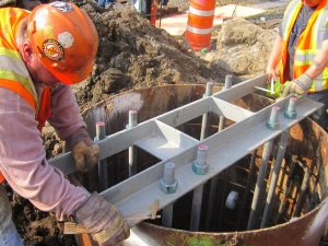
Anchor bolts are used on concrete surfaces. It acts as a fastener between a concrete surface and part which is to be fastened or joined.

Generally a concrete epoxy is applied inside the hole (made in concrete slab). Anchor bolt is then twisted inside this epoxy. After epoxy dries, a firm and strong joint is produced. This type of bolt transfers both tension and shear loads.
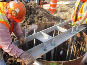
types of bolts with pictures
Image: Workers securing structure using anchor bolt
Image credits: “CH053 – Catenary B-914E North Rebar and Anchor Bolts (03-29-2012)” by MTA C&D – EAST SIDE ACCESS is licensed under CC BY 2.0

Types of anchor bolts

Anchor bolts are of two types depending upon when they are used-

  • Cast in place: These are installed before pouring of concrete. Examples of cast in place anchor bolts are hex head bolt, L bolt, J bolt etc.
  • Post installed: These are installed after pouring of concrete. Examples of post installed anchor bolts are Undercut anchors, sleeve type anchors, stud type anchor etc.

Carriage bolt

Carriage bolts are typically used to fasten a metal and wood or fasten two woods together. Some are specially designed such that they are used for fastening two different metals.

This type of bolt is distinguished from other bolts by its mushroom shaped head. It has a square cross section just below the head and then circular throughout. This makes the bolt self-locking when put inside a hole with square cross section.

Carriage bolt
Image: Carriage bolts
Image credits: “Threaded” by Thad Zajdowicz is licensed under CC BY 2.0

Elevator bolt

Elevator bolts, as the name suggests, are used in conveyer belt systems.

They have a large flat head and are designed to hold canvas belts. They are very strong and can be used in home toolkit. They are also called as bucket bolts and used a hex nut.

Flange bolt

  It has a flange like feature just below the head which allows the bolt to carry high amount of loads and becomes easier for production.

 A flange bolt finds its application in automotive and plumbing industries.

Hanger bolt

Hanger bolts are headless bolts that are typically used to join wood to metal.

These bolts do not have heads. They have wood or slow threading on one side and machine threading on other. They may require a nut depending upon the load applied.

Hexagonal bolt

Hexagonal or hex bolts have a distinct hexagonal head. These bolts come in variety of finishes and find applications in automotive and construction industry.

The hexagonal shape of its head makes the grip stronger and easier for the worker. It can be loosen or tighten by hand also. They are available in both partially threaded and fully threaded types. They can carry high tensile loads.

Huck bolt

Huck bolts have different locking mechanism than other bolts. Where most bolts use a nut for locking, huck bolts use a cylindrical collar which has a smooth internal diameter. This collar is placed on a pin with locking groves.

These bolts provide direct meta to metal contact which reduces the effect of transverse vibration.

Lag bolt

Lag bolts are one of the toughest fasteners. They are thick and usually have a hexagonal head to account for force needed to install them.

These bolts are used in construction industry to fasten pieces of lumber together. It provides a durable connection due to its high strength. These bolts can bear heavy loads.

Plow bolt

Plow bolt has a unique feature, that is, a non-protruding head. This bolt has a square or hexagonal cross section below the head which is used to tighten or loosen the bolt.

This type of bolts are usually used in farm and road construction industry.

Square head bolt

As the name suggests, this type of bolt has a square head. These type of bolts were used when hexagonal bolts didn’t enter the market.

These bolts are used mostly for aesthetic purposes i.e. for giving a rusty old fashion look.

Stud bolt

Stud refers to a threaded bar. Stud bolt is simply a cylindrical bar having threads at both ends. Two nuts at each end in locking the system.

Usually one end of the stud is kept fixed and other moving. So it finds its application in machines where one end is mobile for example in lathes.

Timber bolt

Timber bolts have flat heads and are used to join two pieces of wood. It has two fins below the head which avoids the bolt to move inside the wood.

T bolt

T bolts have a T shaped head. These are widely used in CNC machines.

U bolt

U bolt have the shape of letter U. These bolts have threads on both the ends and are locked with the help of nut. These bolts have threads on both the ends.

Tower bolt

Tower bolts are used in doors. It is used as a stopper for doors that is it locks the door.

Eye bolt types

Appears as a hook, eye bolt is used for lifting applications. Eye bolts can be used in pushing, pulling, hoisting, anchoring applications etc. The main parts of eye bolt are- eye, shoulder and shank.

Eye bolt has two types, they are-

  • Shouldered eye bolt- It has a shoulder on top of the shank. This allows the bolt to bear angular stresses as well. If locked properly, this bolt allows side stresses as well.
  • Non-shouldered eye bolt-Shoulder is absent in non-shouldered bolts. Due to this, only vertical (in-line) stresses can be are allowed else the bolt will fail.

Types of nuts

Nuts are used for locking the bolt in its place. They have a circular cross section and have inner threads that lock with external threads of bolt.

According to the type bolt used, the type of nut also varies. Various types of nuts are-

  • Axle hat nuts
  • Hex nuts
  • Jam nuts
  • Lock nuts
  • Push nuts
  • Rod coupling nuts
  • Speed nuts
  • Square nuts
  • Tee nuts
  • Wing nuts

Types of failures in bolts

Every mechanical component fails after certain point of time.

Excessive stresses can also cause failure in bolts. According to type of stress, bolt failure can occur in following ways-

  • Shear failure
  • Tensile failure
  • Bearing failure of bolt
  • Bearing failure of plates
  • Tensile failure of plates
  • Block shear failure

Bolt finish types

Surface finish is an essential feature of any mechanical component. Frictional forces acting on a smooth surface are lesser than those acting on a rough surface.

Common ways of finishing in bolts are-

  • Zinc electroplating
  • Galvanising
  • Other techniques include using of black oxide, blue phosphate.

Practice questions

1. What are types of foundation bolts?

Foundation bolts are used for securing a machine to the base or support. The base acts as the foundation here.

Most commonly used foundation bolts are anchor bolts. These bolts bear the weight of the structure. These bolts transmit stresses to the foundation that incurred from the structure.

2. What is bolt pretension and is it different from bolt preload?

Bolt pretension or bolt preload is the tension created in the joint due to compressive force exerted by the nut.

This is very essential for any joint because it gives a tight sealed joint. A lose joint may lead to bolt failure or simply failure of whole system. Preloading ensures a proper joint.

3. What is the difference between a bolt and a machine screw?

Although both screws and bolts are fasteners having external threads, they both have certain features that vary.

Bolt is a mechanical fastener that uses a washer or nut to tighten the joint. A screw is a tapered mechanical fastener that doesn’t use washer or nut. They are simply locked with the internal thread of hole. Sometimes, screws create their own threads to get locked inside the hole.

4.  What is the difference between bearing bolt and friction bolt?

The principle difference between bearing bolt and friction bolt lies in the name itself.

In bearing bolt, the stresses are generated from the sides of hole that is bolt contacts with the sides of hole. In friction bolt, the stress is transferred across the plates with the help of friction. The bolt is tightened to clamps which creates high pressure among the parts.

5. What is the difference between a wedge anchor bolt and a sleeve anchor bolt?

Wedge anchor and sleeve anchor are both used for supporting the structure. The difference lies in the type of support and material on which it is to be used.

Wedge anchors are used in heavy duty applications are mostly used for poured concrete. On the other hand, sleeve anchor is used in light duty applications and can be used in brick and mortar where wedge anchor can’t be used.

6. What are screws without heads called?

Headless screws or screws without heads are also called as set screws.

These screws have thread at both the ends and are designed to join two parts together at both the ends.
Wind Turbine Efficiency: 11 Complete Quick Facts

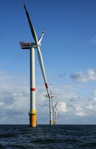
Windmills D1 D4 Thornton Bank 194x300 1

Wind turbine energy production is a growing field of electricity generation; in 2020, the total wind power capacity in the world is 743GW. As the wind plants are producing less pollution, the demand for wind power generation is growing.

The efficiency of a wind turbine depends on many factors, like the type of turbine, the blade geometry, available wind velocity etc. 59% is the maximum efficiency that can be achieved by a wind turbine. The practical efficiency of a wind turbine varies between 30 -45%, and it may rise to 50% during peak wind.

If the turbine is working at 100% efficiency, the wind speed after striking the turbine becomes zero, which is impossible.  

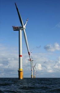
wind turbine efficiency
Windt turbine Credit : https://commons.wikimedia.org/wiki/File:Windmills_D1-D4_(Thornton_Bank).jpg
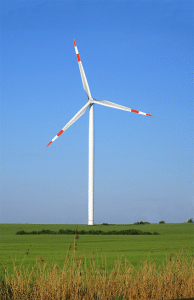
Wind turbine
Wind turbine Credit:https://commons.wikimedia.org/wiki/File:Wind_turbine.gif

Wind turbine efficiency formula

The calculation of efficiency is essential; the efficiency helps to compare the performance of different wind turbines and optimum wind speed for maximum efficiency.

Co-efficient of power is the more common word for efficiency of the wind turbine. The Cp is defined as,

gif

The amount of electricity produced by a wind turbine can be calculated from the generator output. The below equation calculates the input kinetic energy,

Where,

gif

A is the covered area of the wind turbine, V is the wind speed, ρ is the air density.

The Cp value varies with respect to the wind speed; hence the efficiency of the wind turbine varies while operating.

Further, the Cp depends on turbine parts, i.e. the turbine blades, shafts and generator. Therefore, the multiplication of aerodynamic efficiency of blades, mechanical efficiency of the shaft and electrical efficiency of generator provide the value of Cp.

Maximum efficiency of wind turbine

The maximum possible efficiency of the wind turbine is proposed by Albert Betz, a German physicist, in 1919. It provides insight into the maximum possible turbine efficiency.

The Betz’s limit shows that 59.3% is the maximum possible efficiency of a wind turbine. Hence, the turbine efficiency never exceeds 59%, including all other losses it comes to 35-45% value in practical cases.  

Let’s assume that the efficiency of a wind turbine is 100% that means the turbine consumes all the air energy. If it happens, the velocity of air after passing the turbine becomes zero. That means the air is not flowing, which hinders the further flow of air. Thus, this is an impossible situation.

Now, if the inlet and exit air velocity are the same, that means no energy is extracted, which gives 0% efficiency to the turbine. Hence the maximum possible turbine efficiency is somewhere between 0 and 100%, excluding these limits.

Betz proved that the maximum possible efficiency is 59.3% for a wind turbine with maths and solid physics.

Types of wind turbines and their efficiencies

A variety of wind turbines are available according to the axis of rotation and design of blades. The most commonly used wind turbine is the Horizontal axis wind turbine. However, other kinds of turbines are also used for appropriate conditions. The different types of turbines are,

Let’s discuss the efficiency of these turbines separately,

Horizontal axis wind turbine (HAWT) efficiency

The horizontal axis wind turbines are commonly used for large plants, where enough space and wind is available. The axis of rotation of the turbine blade is parallel to the earth surface.

The efficiency of HAWT varies between 35-50%. Currently, HAWT has the highest efficiency.

The captured wind energy by wind turbine depends on the area covered by the turbine blades. For a HAWT, the area is calculated as follows,

A = πL2

Where, L is the length of blade. The length varies between 20 to 80 meters.

Usually these wind turbines are used for large production plants. Most common horizontal wind turbine is 3 bladed, and the colour of turbines usually white for visibility by aircraft.

Horizontal
HAWT Credit: https://commons.wikimedia.org/wiki/File:Micon-Turbine.JPG

Vertical axis wind turbine (VAWT) efficiency

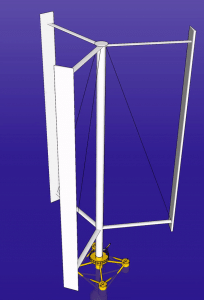
The vertical axis wind turbines are commonly used for small energy production where the space is constrained. The axis of rotation of blades of vertical axis wind turbines is perpendicular to the Earth surface.

The efficiency of VAWT is less compared to HAWT. 

As discussed, the efficiency depends on the area of turbine blades exposed to wind. For VAWT, the area exposed is,

A = DH

Where D and H are the diameter and height of the blades.

Different kinds of VAWT are available. Darrius wind turbine and Savonius wind turbine are common VAWT. The efficiencies of these two are discussed below.

Vertical Axis Wind Turbine offshore
Vertical axis wind turbine. Credit: https://upload.wikimedia.org/wikipedia/commons/1/1f/Vertical_Axis_Wind_Turbine_offshore.gif

Darrius wind turbine efficiency

Darrius wind turbine is a VAWT.

The efficiency of the Darrius wind turbine is between 30-40%. The usage of these turbines are limited even though these are having high efficiency mainly due to inability to self-start.

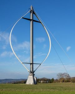
Darrius turbine is a lift based turbine. The figure shows a Darrius wind turbine. As shown below, a number of aerofoil blades are mounted on a vertical shaft that rotates. The blades are stressed only in tension for these turbines due to the curvature. The design is developed by  French engineer Georges Jean Marie Darrieus. These are commonly used near to human habitat, on the top of a building or in the centre of a road. However, the protection of the turbine is tough in extreme conditions.

Darrieus Rotor Ennabeuren 3256
Darrius wind turbine Credit:https://commons.wikimedia.org/wiki/File:Darrieus-Rotor_Ennabeuren-3256.jpg

Savonius wind turbine efficiency

Savonius wind turbine is a different type of VAWT. Unfortunately, the efficiency of these turbines is very low.

The efficiency of the Savonius wind turbine varies between 10-17%. Even though the efficiency is very low, due to the simple structure and reliability of the turbine, these are used to produce a small amount of electricity in appropriate locations.  

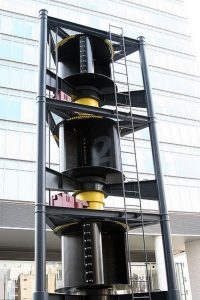
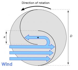
Savonius turbine is drag based turbine. The figure shows an actual Savonius wind turbine. The top view of the blade is also shown in the below figure.

399px Savonius wind turbine
Savonius wind turbine Credit: https://commons.wikimedia.org/wiki/File:Savonius_wind_turbine.jpg
660px Savonius rotor en
Top view of Savonius wind turbine. Credit: https://commons.wikimedia.org/wiki/File:Savonius-rotor_en.svg

Finnish engineer Sigurd Johannes Savonius developed the Savonius wind in 1922. There are two types of blade design for Savonius wind turbine, barrel design and ice wind design. The top view barrel wind turbine is shown above. The blades are half-cylindrical; the barrels are not meeting in the centre; they are away from the centre, which enables the free motion of wind in the blade.

Bladeless wind turbine efficiency

The bladeless wind turbines are a particular type of wind turbine, these turbines don’t have revolving blades, and the turbine works based on vortex-induced vibration.

The efficiency of a bladeless wind turbine is very less compared to any other wind turbine. However, lightweight, cost-effectiveness and less maintenance are the advantages of the bladeless wind turbine. In addition, the turbine requires less space; hence, more turbines can be installed than the usual wind turbine.

Archimedes wind turbine efficiency

Archimedes wind turbine is a recently developed technology. These are small structures and can be used on rooftops, on roads, etc.

Compared to conventional wind turbines Archimedes wind turbines are more efficient. In addition, the turbine reduces many other problems related to conventional turbines. 

For example, the noise produced by Archimedes wind turbines is significantly less compared to the conventional turbine. The shape of the turbine is modelled similar to the spiral of a Nautilus shell. This shape enables the turbine to self-adjust the turbine face according to the wind flow. 

Factors affecting wind turbine efficiency

The efficiency of wind turbines are already discussed above, from that the factors affecting turbine efficiency are,

  • The wind speed.
  • The air density.
  • Blade radius.
  • Type of wind turbine

Wind turbine efficiency comparison

Let’s conclude the wind turbine efficiency here. The wind turbine efficiency is tabulated below.

Turbine Efficiency
Horizontal axis wind turbine 30-45
Vertical axis wind turbine 10-40
Darrius wind turbine 30-40
Savonius wind turbine 10-17
bladeless wind turbines Very less

For more posts on Mechanical Engineering, please follow our Mechanical page

Heat Pump Work In Winter: 13 Important Concepts

Heat pump 300x206 1

How does a heat pump work in winter? It is always a curious question for all of us. We know that in winter the objective of heat pump is to heat the room. Let’s analyse the working of heat pump in winter.

During winter, the liquid refrigerant sucks heat from outside air and becomes vapour form; the vapour refrigerant is compressed to high temperature and pressure. Then the refrigerant is allowed to pass through the room. During that period, the refrigerant releases the heat to the room, by which the room temperature increases. 

This system is a good option for places where mild winter occurs, and it can save energy compared to conventional heating. However, for severe winter, the heat pump alone is not a good alternative. The hybrid system is used in that scenario.

There different type of heat pumps are available. The classification is based on from where the heat is taken, i.e. the location of evaporator. Some of the types are :Air source heat pump, Ground source heat pump, water source heat pump etc.

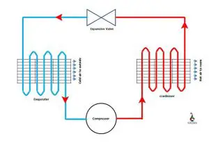
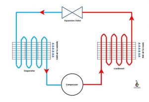
A schematic diagram of heat pump with main components are shown in figure below;

How Does A Heat Pump Work In Winter
The main components of a heat pump
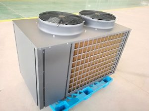
small air source heat pump 4963069 960 720
The outside unit of a small air source heat pump Credit: https://pixabay.com/de/photos/kleine-luft-w%c3%a4rmepumpe-4963069/

How does a ground source heat pump work in winter?

The temperature below few feet from the ground is at a stable temperature of 55oF irrespective of the season. Let’s see how this fact is utilised to run a heat pump.

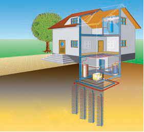
In ground source heat pumps, series of strong pipes are installed below the ground; this is the ground source heat exchanger. Coldwater from the heat pump is circulated through these pipes, and the water absorbs heat from the ground. Then, the water transfers this heat to the refrigerant in the heat pump. 

A schematic diagram is shown below.

Heat pump
Ground source heat pump Credit :https://www.flickr.com/photos/sagabardon/5086132916

The ground source heat pump eliminates the burning of fossil fuel; hence this is environment friendly. Germany, USA, Sweden, Canada, Switzerland are the main countries using this heat pump.

What temperature is a heat pump not effective?

The heat pump is not advised in all temperatures. The ambient temperature influences the effectiveness of the heat pump.

As the ambient temperature decreases the effectiveness of heat pump decreases, from the research the limiting ambient temperature is calculated as 40oF. Hence, a heat pump is advised to use when the ambient temperature is above 40oF. The heat pump becomes less effective than other heating options when the temperature reduces to 25 to 30oF.

Hence, we use an alternative system in those regions where the temperature falls below 40oF. Fossil fuel or any cheap fuel is burned to extract heat in these regions during peak winter.  

The heat pump is working between two temperature limits, room temperature and ambient temperature. Therefore, the performance of heat pump depends on both these temperature. One can assume that if the ambient temperature is low, the heat pump consumes more work to extract the heat; hence efficiency decreases.

Let’s analyze the effectiveness of heat pumps mathematically. The effectiveness of a heat pump is measured as Coefficient of performance (COP). COP is defined as

COP = (Heating effect)/(Work done to the system)

Let’s analyze the COP of a Carnot cycle. Carnot cycle is an ideal cycle that has the maximum COP.

The COP of the Carnot cycle is defined as;

COP = Thot/Thot – Tcold

Tcold is the ambient temperature, and Thot is the room temperature. Let’s assume that we set 68oF in heat pump, hence the room temperature is 68oF. Now let’s assume two conditions when the ambient temperature is 40oF and 20oF.

When these temperature conditions are applied, we get COP of 11.5 and 6.7 for the ambient temperature of 40oF and 20oF, respectively.

(Note: Care should be taken while calculating the COP, the temperatures should be in Kelvin scale or Rankine scale.)

Here, the COP is reduced when the ambient temperature is reduced. The calculated COP is for the maximum possible cycle. This COP cannot achieve in an actual cycle. Hence, we can conclude that as the ambient temperature decreases the COP of heat pump decreases.

What temperature should I set my heat pump in the winter?

This is always a concern for many of us while operating a heat pump.

The human comfort is the primary objective of a heat pump in home. From scientific researches, it is concluded that 680F is best for human comfort during winter. It is advised to reduce the operating temperature further when we use the heat pump continuously. 

Can heat pump work below freezing?

The question here is what happens when the ambient temperature is below freezing point. Is it safe to operate?

Yes we can use heat pump in freezing conditions. The freezing point of refrigerant used in a heat pump is far below the freezing point of water; hence the refrigerant in the heat pump will not freeze even though ambient temperature is below the freezing point of water.

If the question is “is it advised to use heat pump in extreme cold?” then the answer is “no it is not advised”

However, in extremely cold conditions it is not advised to use heat pump. We discussed the effectiveness of heat pumps in previous sections. When the temperature is less than 40oF, the effectiveness of the heat pump reduces; hence heat pump consumes more energy than simply burning fuel.

How can I make my heat pump more efficient in the winter?

Some tips to improve the efficiency is given below.

  • Clean the filter frequently.
  • For fast heating of the room, do not set the heat pump temperature very high.
  • Don’t heat the spaces which you are not using.
  • Perfectly close all the ventilations in the room.
  • Always provide enough space in indoor and outdoor unit of heat pump for free flow of air.
  • Only put emergency heat mode when it is an emergency.
  • Make sure that the outdoor unit is easily accessible for cleaning.

Why is my heat pump blowing cold air when the heat is on?

There are mainly three reasons that you may feel that your heat pump is blowing cold air.

  • The heat pump is working correctly, but you are feeling it cold.
  •  The heat pump started working on defrost mode.
  • The heat pump is not working correctly.

Let’s discuss each point separately.

  • The heat pump is working correctly, but you are feeling it cold.

The heat pump is working correctly; however, when the ambient temperature is very low, the heat pump’s effectiveness and the ability to increase the temperature reduces. In these situations, the heat pump is heating the air, but you do not feel it as the temperature of heated air is far below your body temperature.

Generally, the electric heating starts automatically in these situations.  

  • The heat pump started working on defrost mode.

When a heat pump is working at a very low ambient temperature, water may freeze around the outdoor unit’s coils. The complete covering of the coil with ice should be avoided. The heat pump works on reverse mode to remove this frost, i.e., it starts cooling inside and heating outside coil.

After 1-2 minutes of operation, the heat pump starts working properly when the frost is completely removed.

  • The heat pump is not working correctly.

This is a serious issue, and you should contact a technician. There are many possibilities like leakage of refrigerant, damages in valves or reduction in heat pump efficiency, etc.

 Should I run my heat pump on auto or heat?

 There are three modes in a heat pump “Heat”, “Cool,” and “Auto”. 

It is advised to set “Heat” mode rather than “Auto” mode in the winter season. This is because the “Auto” mode may cool the room on a sunny winter day, which is unnecessary, i.e., the heat pump automatically gets reversed its operation, which should be avoided.

Should I turn my heat pump off in extreme cold?

The extreme cold situation may occur in winter in many countries.

It is advised to stop using the heat pump in an extreme cold situation as the effectiveness of the heat pump decreases, which leads to increased energy consumption, as discussed above.

Usually, the heat pump comes with an electric heating facility. Hence, in an extreme cold situation, the heat pump gets switched off, and electric heating starts automatically.

How long should a heat pump run per day?

We know that the old furnace heating technique won’t run continuously for a long time. What about the heat pump?

The heat pump can run continuously throughout the day if it is required. The advanced heat pumps come with automatic sensors, which allow the heat pump to stop operating when the required temperature is achieved; it starts automatically when the temperature drops. Hence, you should not worry much about energy consumption.

However, you can reduce energy consumption by manually setting the off time in a heat pump.

How do I know if my heat pump is defrosting?

Defrosting is very common in a cold situation. Defrosting cycle may be required for the efficient working of the heat pump.

You can know that the heat pump is working on defrosting cycle if the following is observed.

  • The indoor fan of the heat pump turns off
  • The heat pump stops heating the room
  • The defrosting indicator light blinks
Ecodan outdoor unit in the snow
Frosting in outdoor unit of heat pump Credit: https://commons.wikimedia.org/wiki/File:Heat_pump_model.jpg

How do I keep my heat pump from freezing up?

The outdoor coils of the heat pump may freeze while operating.

The defrost cycle is to avoid the freezing up of the heat pump. The operation of the heat pump reverses in defrosts cycle, and during that period, the heat pump cools indoors and heat outdoor so that the ice melts. This cycle operates automatically. Within 2-3 minutes, the heat pump starts operating normally. 

How do you unfreeze a heat pump in the winter?

You can unfreeze the heat pump in the following ways,

  • Defrosting cycle. In heat pumps defrosting cycle operates automatically. 
  • Remove the frost manually; you can pump water to the frost until it is melted. Or you can chip the frost with a tool

How much frost is normal on a heat pump?

We cannot say the normal frost quantitatively.

There are two conditions when you can say that the frost is too much in a heat pump.

  • When the frost prohibit the flow of air to the heat pump
  • When the frost is staying on the coils for more than 2 hours.

If these conditions are observed, it is advised to contact an operator as the defrost cycle is not running in your heat pump.

How does a pool heat pump work in winter?

The working of a pool heat pump is similar to the air heat pump.

The pool heat pump is used to heat the water to the swimming pool. In this, the condenser transfers heat to the cold water. The other processes are similar to the room heat pump. Hence, the condenser is dipped inside the swimming pool, and the remaining unit is outside the pool.

For more posts on Mechanical Engineering, please follow our Mechanical page.

Hammer: 15 Interesting Facts To Know

1200px IKEA hammer 300x200 1

Hammer is a tool in which heavy metal is mounted on a handle,

The hammers are used for various applications, from pressing a nail into the wood to medical examination of nerves in the legs.

Different types of hammer, parts of hammers , its uses and the making of hammer is discussed in this article.

The below figure shows a typical example of a hammer.

Different types of hammer and their uses

There are different types of hammer in the industry, each have particular uses. Some of therm are listed below,

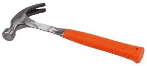
Claw hammer

The main application of a claw hammer is to push the nail into an object or pull the nail from the object.

The main difference between a regular hammer and a claws hammer is the part claw, which helps pull the nail from the object.

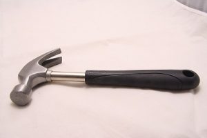
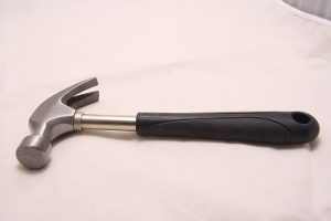
Claw hammer
Claw Hammer Credit: https://pixabay.com/de/photos/klauenhammer-hammer-werkzeug-2202195/

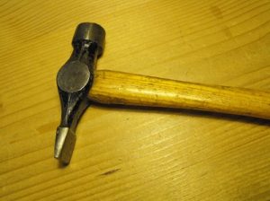
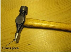
Cross peen hammer

The main applications of cross peen hammers are to push the nail into an object. The advantage of a cross peen hammer is, it can be used to hammer the nail when there is a restriction in space.

Both the surfaces are flat. The cross-section of one side of the hammer is circular, which can be used for general purposes. The other side has a rectangular section with a small cross-sectional area.  This side is known as peen. It can be used when the space is restricted.

Cross peen hammer
Cross peen hammer Credit: https://commons.wikimedia.org/wiki/File:Warrington_hammer.png

Straight peen hammer

The difference between straight and cross peen hammer is the peen is oriented 90o with each other. The application is similar to cross peen hammer.

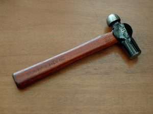
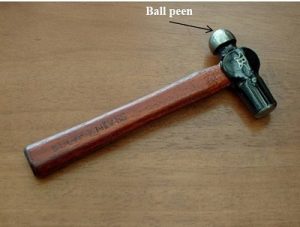
Ball peen hammer

The ball-peen hammer is also similar to a straight peen hammer. However, the peen shape is hemispherical in the case of the ball-peen hammer.

The peen surface is used for rounding the edges of metals, for example, in the case of riveting.

Ball peen
Ball peen hammer Credit: https://commons.wikimedia.org/wiki/File:Buck_Knives_Hammer_(5075278861).jpg

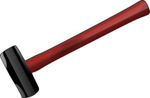
Sledge hammer

These are large hammers. The primary purpose of this is to break large rocks and concrete. Both the shape of the hammer is flat round and symmetrical. It has a large handle, and the weight is 3-16lbs

Sledge
Sledge Hammer Credit:https://pixabay.com/de/vectors/hammer-vorschlaghammer-schlitten-35244/

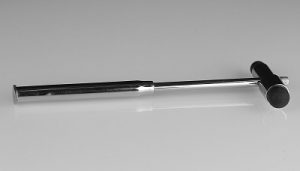
Clinical hammer

Doctors use the clinical hammer. It is also called a reflex hammer. The primary purpose of these hammers is to study nerve conduction in the human body.

The hammerhead is made up of rubber. The doctors hammer on the nerves and observe the reflexes; hence it is called the reflex hammer.

Refelx hammer
Clinical hammer Credit: https://commons.wikimedia.org/wiki/File:Percussionshammer.jpg

Club hammer

A club hammer is miniature of a sludge hammer. The weight, size, and length of the handle are less compared to the sledge hammer. However, the shape of the hammer head is similar to sledge hammer. The handles usually are wood. The weight is around 2-3 lb.

It is used for light demolishing works, chiselling, etc.

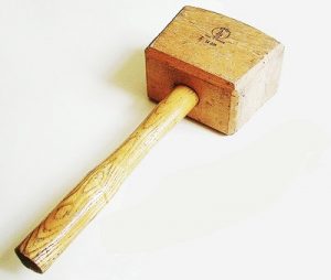
Wooden hammer or mallets

The primary purpose of the mallet is to knock the wooden pieces together or to drive chisels etc.

The hammer head is made up of wood in these hammers.

Mallet and chisel
Mallet Credit : https://commons.wikimedia.org/wiki/File:Mallet_and_chisel.jpg

Power Hammer

These hammers are powered by machinery, not with human muscle. In the power hammer, steam is used to create pressure. These are mainly used in the open die forging industry. These are derived from tripping hammers, where tripping hammers are ancient power hammers. In a power hammer, the desired position of hammer is achieved slowly. However, the hammering stroke is fast and instantaneous, hence get better hammering effects.

powerhammer
Power hammer Credit: https://commons.wikimedia.org/wiki/File:Massey_power_hammer,_Murikka_1.jpg

Parts of hammer

We can separate the parts of a hammer into two categories, Common parts, and special parts. The common parts are there in all types of hammers, and the special parts are available only in a specific hammer, and these are for special purposes.

Common parts of a hammer

Handle

The handle is a long structure in a hammer. When we buy a hammer, we will be looking into the size and shape of the hammer for the user’s comfort. The handle may be wood or steel generally. The steel handle will have the grip to hold the hammer. If the eye diameter is small for a hammer head, the handle may be made in a conical shape to have enough size toward the holding end for easy holding. The cross-sectional shape of the handle can vary; generally, the round is preferred, oval also can be used. The handles should have smooth edges for holding comfortably.

The head is the hammering part. The shape varies tremendously according to the hammer. The hammer at least has one flat side. In sludge and club hammers, both sides are flat. The clinical hammer is an exception; it does not require a flat face in the head.

The head itself has different parts. The particular parts which are peculiar to a hammer are made on the head. The different head parts are discussed below.

Face

The face is the flat surface in the hammer that is used for striking. The hammer has at least one face. The size of the face depends on the application. For example, the sledge hammer has a large face; however, the tack hammer has a small face. The sledge and claw hammer has two faces. Both the faces have the same application; we can use any of these for striking.

Neck

The portion where the head and handle are connected is known as the neck.

Throat

The throat is the portion between the neck and face. In the above figure, we can see the throat section, i.e., for claw hammers, the throat is visible. The sledge and club hammer don’t have a throat.

Cheek

It is the side of the head.

Eye

The eye is the hole that is provided in hammers to connect with the handle. In some hammers, the head and handle come as a single unit. In that case, the hammer doesn’t have an eye. Generally, for wooden handles, we can separate the handle and head. We insert the handle to the eye in these cases. The advantage is that we can change the handle if any damage is occurred to the handle, instead of changing the complete unit.

Special parts of hammer

Different hammers have unique applications. Therefore, the hammer head is made in such a way that the application is achieved easily. Such particular parts are discussed here.

Claw

The claw is provided in a claw hammer to pull out the nail. The nail head is inserted between the two openings of the claw, and then the hammer is pulled so that the nail comes out. The other face is used for the hammering of the nail as usual.

Peen

These are provided in straight, cross, and ball peen hammers. These peens have different applications. The difference between these hammers is the shape of the peen. The straight and cross peen is used when there is not enough space to hammer the nail with the large face like in corners of a wall. The ball-peen is used for rounding the metal edges.

Cross Part 1
Cross peen Credit: https://commons.wikimedia.org/wiki/File:Warrington_hammer.png
Ball part 1
Ball Peen Credit: Credit: https://commons.wikimedia.org/wiki/File:Buck_Knives_Hammer_(5075278861).jpg

Material used to make the hammer

The hammer’s head is made of strong material, as it has to withstand the repeated blow. Generally, heat-treated high carbon steel is used. The high carbon in steel provides high hardness and strength to the hammer. The heat treatment reduces the stress hence improve the fatigue strength.

Wood or steel is used to make the hammer’s handle. The steel hammers are used for small hammers, and the steel handle is permanently attached to the head. A grip is provided in this steel handle.

The wooden handles are attached to the head manually; hence wooden handle can be replaced. The handle is inserted into the eye of the hammer head and appropriately fixed. The re-fixing is required after continuous use. The wooden handle is used for large hammers (Sledge hammer), as the wood act as a vibration damper.

Hammer making

The hammers are mainly two units head and handle. Generally, both are made separately.

The head is made by hot forging operation. Initially, a large hot bar is cut into small pieces and inserted between two dies. The dies have the mirror shape of the head. One die is stationary; the other is moving. After inserting the metallic bar, the moving die is moved toward the stationary die, by which the inserted metal between the dies takes the shape of the hammer head.  After the forging, the hot forged head is cooled to room. Lastly, the surface finishing operation is carried out to remove the unwanted projections in the head.

Metal or wood is used to make hammer’s handle. In the case of the wooden handle, the appropriate shape of the wooden piece is cut, and the handle and head are correctly assembled. A hot extrusion process is used to make the steel handle.

Uses of hammer

The hammers are extensively used in different industries, general works, and real life. As a result, it is one of the most common equipment. Some uses of hammers are listed below.

  • Breaking large objects like rock, concrete etc.; The sledge and club hammer is used for this purpose.
  • The hammering of a nail;  this is the most common use of claw and peen hammers.
  • Pulling out the nail; generally claw in the claw hammer is used.
  • Forging;  in the forging industry, hammers are extensively used. Peen hammers and club hammer is generally used in in the case human forging. The power hammers are used for significant shape change.
  • Carpentry, the wooden mallets are used by carpenters to strike wooden components.
  • Examining the reflex of the human nerve; the clinical hammers are designed for this purpose. Doctors use this hammer to strike at a specific location in the nerve and observe the reflex; based on the reflex, the doctor finalizes whether the nerves are working correctly or not.

Choosing hammer

We have to follow some steps to choose a hammer. This is basically user-centric, i.e. It is based on your comfort. Basically, we have to follow three steps, which are discussed below.

  • Select hammer based on the application

We have to select the hammer according to the application. For example, if your application is striking and pulling out nails, you should go for a claw hammer, and if you want to break a block of concrete or rock, you should choose a sledge hammer.

  • Select the weight and size of the hammer

The weight and size are the next parameters. Next, we have to choose the weight and size of the hammer. The size here represents the size of the face. The size of the face should be so that, when we use the hammer, it won’t miss the nails. The weight is concerned when we chose a sledge hammer. The weight should be high for better hammering effect; however, the person should be able to lift the hammer with that weight easily.

  • Select the grip

The grip of the hammer is essential. It is for human comfort. If the hammer grip is not chosen correctly, the hand may feel pain and limit the hammer’s continuous usage. The steel hammer comes with the proper grip. However, you should check it once. In the case of wooden handles hammer, the size of the holding end should be enough for the person to hold it properly.

FAQs

What is the metal part of a hammer called?

Generally, the hammers have a metallic part and a wooden part. 

The metallic part of the hammer is called as the head of the hammer. The shape and size of the head vary according to the applications.

How many parts does a hammer have?

The hammers have different parts according to the application.

Generally, we can say the hammer has ten parts: Grip, Handle, Neck, Eye, Throat, Face, Head, Cheek, Eye, Claw, or peen.

All these parts are not necessary. For example, in a claw and peen hammer, all these parts can be seen; however, in a sledge hammer, the claw or peen and throat are not present.

What is a hammer drill?

The drill is the equipment used to make a hole in an object; the object may be a wall, wood, or a metallic piece.

A typical drill operates by rotating the cutting tool. While the cutting tool cuts the material, the operator has to push the drill into the hole. If the object is too strong, like a concrete block, the manual pushing may not be enough to push the drill into the hole. 

In a hammer drill, a hammering effect is provided to the drill bit additional to drilling; hence the drilling operation becomes easy. Therefore, the hammering effect reduces the manpower required.

What is a piano hammer?

The piano is a musical instrument in which a string is vibrated, and we hear the sound of vibration.

The piano hammer is used to make the vibration in the string when we press a key in the piano.

There are three components to make sound in piano. The keys, hammers and strings. The piano has 88 keys. When one key is pressed it actuates the hammer connected to that key and the hammer strikes a string or set of strings; thereby, the strings start vibrating. Thus, we hear the vibration of these strings. Each hammer strike produces a different set of vibrations; hence distinct sound is produced for each key.

There is another mechanism known as a damper to stop the vibration of these strings.

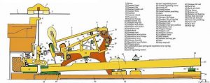
The given figure shows different parts of a piano mechanism. The hammer mechanism can be seen in the figure.

Piano Hammer
Parts of piano Credit: https://www.flickr.com/photos/rain0975/2509155870

Why is it good to make hammers out of high carbon steel?

Heat treated high carbon steel is used to make the hammer head.

The high carbon in steel provides high hardness and strength to the hammer. The heat treatment reduces the stress hence improve the fatigue strength. 

What is a hammer mill?

The hammer mill is mechanically powered hammer that is used in various industries.

Hammer mills are used for crushing large materials into small pieces by the continuous action of tiny hammers. The hammers are attached to a rotor, which rotates at high speed. A cylindrical drum covers the whole rotor hammer mechanism. The drum has two openings, the material to be crushed is inserted from the top, and the fine materials are taken from the bottom. The main application of hammer mills is crushing large rocks into small pieces, shredding automobile parts, etc.

What are mechanically powered hammers?

There are two types of hammers, mechanically powered and Hand powered.

The mechanically powered hammers are different from man-powered hammers.

The mechanically powered hammers use energy from a source other than manpower. The structure of a mechanical hammer is entirely different from the regular hammer; however, the working principle is the same. Examples of mechanically powered hammers are hammer drill, steam hammer, jack hammer, trip hammer, etc.

For more posts on Mechanical Engineering, please follow our Mechanical page.

Magneto Ignition System: 11 Important Facts

Magneto Ignition System edited 300x225 1

Have you wondered what happens to petrol when it reaches the fuel tank? Well the answer is simple, the fuel is ignited to produce a certain amount of thermal energy which then gets converted into mechanical energy (rotary motion of wheels). 

There are two ways by which fuel can be ignited- with the help of electric spark or by applying high pressure. Now the question arises, how to create a spark inside the engine? This is the situation where magneto ignition system comes into play.

In spark ignition engines (petrol engines), a spark is required to ignite the fuel. The source of electricity to create a spark may vary according to engine requirements. Read this article further to get a deep insight on how does a magneto work.

What is magneto ignition system?

Spark ignition engines create a spark to ignite air-fuel mixture. This spark is created with the help of an ignition engine.


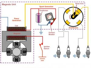
An ignition system that uses a rotating magnet (magneto) for generating electricity is known as magneto ignition system. This electricity is used to power spark plugs.

Magneto ignition system diagram

How does magneto work
Image: Magneto ignition system
Image source

Parts of magneto ignition system

Magneto ignition system uses following parts-

Many parts are employed which work in harmony to give desired output. The basic parts of magneto are discussed below-

  • Magneto
    Magneto refers to a group of rotating magnets used for producing high voltage. The rotational speed of engine (rpm) is directly proportional to the voltage produced by rotating magnets. Based on the rotation of parts, magneto is of three types-  

    -Armature rotating type
    -Magnet rotating type
    -Polar inductor type
  • Distributor
    As the name suggests, distributor invites ignition surges and then distributes it among individual spark plugs. Distributor has a rotor in the center and metallic electrode on the periphery.
  • Primary and secondary winding
    Primary winding act as the input that is draws the power from source and secondary winding having more number of turns acts as output. Secondary winding is connected to distributor.
  • Cam
    Cam facilitates the motion of magnet. It is connected to the poles of magnet.
  • Circuit breaker
    Cam motion is designed in such a way that it breaks the circuit at certain intervals. When the circuit is breaks, the capacitor starts charging by primary current.
  • Capacitor
    A capacitor is an assembly of two metallic plates placed at a small distance from each other.  Capacitor stores charge.
  • Spark plug
    Spark plug is used for igniting air-fuel mixture inside the engine cylinder. Spark plug has two metallic electrodes separated by a small distance.

How does a magneto work?

Magneto system employs a rotating magnet as the source of electricity, rest of the working is similar to the battery ignition system. Working of magneto ignition system is explained briefly below-


As the engine rotates magnet inside the coil, an EMF is generated and so a current starts flowing through the coils. As the poles of magnet start moving away from the coil, the magnetic flux begins to decrease. At this point, the cam breaks the circuit (cam-type contact breaker).

As the contact breaker breaks the circuit, the flow of current disrupts. As a result, capacitor starts charging and voltage on the secondary winding increases rapidly. The voltage increases up to such an extent that it is able to jump small gaps. When this happens, spark is created and fuel-air mixture is ignited.

Types of magneto ignition systems

Based on the engine rotation, magneto ignition system can be of following type-

  • Magnet rotating type- In this type, magnet rotates and armature is kept fixed. As a result there is a relative motion between magnet and the windings. In modern days, this type of magneto ignition system is commonly used.
  • Polar inductor type- In this type, both the coil and magnet is kept fixed. The moving part here is a soft iron core having projections at fixed intervals.
  • Armature rotating type- In this type, magnet is fixed and the armature rotates.

Dual magneto ignition system

Usually a single magnet is used in small engines like in that of two wheelers. Big engines like that of aircrafts need an extra magnet for safety. In dual magneto ignition system, two magnets are used instead of one. This increases the safety factor of the engine.

Dual magneto ignition system is used in aircraft engines where each engine cylinder has two spark plugs and each spark plug is fired by its individual magneto. In case where failure of one magneto takes place, other magneto keeps the engine running with a slight decrease in efficiency.

High tension magneto| Low tension magneto

There are two types of magneto- high tension and low tension magneto. Their working principle being same in ignition system. Both of these magnetos have a minute difference between them.

High tension magneto produces pulses of high voltage that are sufficient enough to jump across the length between two electrodes of spark plug. This type of magneto works when the circuit breaks, only then the voltage rises up to desired level. The main disadvantage of this type of magneto is that it deals with very high voltage.

Low tension magneto produces a low voltage that is distributed in the transformer coil which is again connected to spark plug. Using a low tension magneto eliminates the need of dealing with high voltages. This type of magneto is generally used in spark ignitors and not in spark plugs.

Battery ignition system| Difference between battery and magneto ignition system

Battery ignition system serves the same purpose as magneto ignition system. It acts as the source of electricity that is used to produce sparks in spark plug.  

Battery ignition system was commonly used in four wheelers but now it is being used in two wheelers as well. A 6V or 12V battery is used to produce a spark unlike magneto ignition system where magneto was the source of electricity.

Battery takes more space hence it was not suggested to use it in two wheelers where space constraint is more. Nowadays compact battery systems are available that can be used in two wheelers also.

The major difference between a battery and magneto ignition system is the source of electricity. In battery ignition system, as the name suggests, battery is used as the source of electricity whereas magneto ignition systems use magneto for generating electricity.

Electronic ignition systems

Electronic ignition systems use electrical circuits having transistors that are controlled by sensors to produce spark. This type of system can ignite even a lean mixture and provides better economy.

Electronic system is divided into two types- Transistor and distributorless ignition system. Electronic ignition system in general, doesn’t use breaker points like those used in magneto ignition system. Hence, this type of system provides breakerless ignition.

Advantages and disadvantages of magneto ignition system

Not every system is ideal, every system has its own pros and cons. It is a design trade off which decides which type of system needs to be used. Following are the advantages of magneto ignition system-

  • It generates electricity on its own hence no need of battery.
  • It occupies less space.
  • No problem of charging or discharging of battery as it doesn’t use one.
  • High efficiency/reliability due to high voltage spark.

Disadvantages of magneto ignition system are-

  • Costlier than other ignition systems.
  • During start, quality of spark is low due to low engine speed. It gets higher with high engine speed.

Practice questions

How does a magneto ignition system work?

Ans: Magneto ignition system works on the principle of Faraday’s first law of electromagnetic induction.

The relative motion between magnet and transformer coils induce an electromotive force (EMF). Due to this, a varying electric current is produced. As rotation of the magnet progresses and poles start moving farther from the coil, a circuit breaker breaks the circuit and disrupts the flow of current.

Due to this, a high voltage is produced at secondary coil which is then distributed to the spark plugs. The voltage is high enough for it to jump across the length between two electrodes of spark plug.

What are the main advantages and disadvantages of magneto ignition system?

Ans: The magneto ignition system has its own pros and cons. Advantages of magneto ignition system are as follows-

  • No batteries are requires as magneto itself generates electricity.
  • Takes up less space than other ignition systems.
  • No problem of discharge as no batteries are used.

The following are disadvantages of magneto ignition system-

  • Expensive as compared to other ignition systems.
  • The voltage produced is directly proportional to the engine speed. So low voltage is produced at start due to low engine speed.

What are the three types of ignition systems?

Ans: To ignite the air-fuel mixture, an ignition system is required. For industrial applications, three types of ignition systems are commonly used-

  • Battery ignition system
  • Magneto ignition system
  • Electronic ignition system

What is the purpose of magneto in an ignition system?

Ans: Magneto is a rotating magnet whose rotation speed is equal to the engine speed.
        
      Pulses of high voltage are required to produce a spark in spark plugs. These pulses are produced by a magneto. The spark produced ignites the air-fuel mixture.

Why magneto ignition system is not used however it has higher efficiency and low maintenance?

Ans:  Magneto system works solely on mechanics of engine rotation hence the voltage keeps varying at different speeds. Electronic ignition system is more efficient overall as it can also ignite lean air-fuel mixture. With use of transistors and sensors, the precision of producing sparks improved. Also, mechanical components are ought to wear after certain period of time.
Because of above reasons, magneto systems are not used these days. However, they were best suitable at the time of their invention.
What route is followed by current in magneto ignition system?

Ans: Current in magneto ignition system is induced by varying magnetic flux around the coil.

The induced current flows through primary winding. A circuit breaker breaks the circuit at certain intervals. Current flow disrupts when the circuit is broken. This results in increase of voltage at secondary winding which is connected to spark plug. As the poles reverse, the flow of current reverses.

What is a more efficient ignition system coil and battery or magneto?

Ans: The answer to this question depends on the basis of comparison.

        If we compare on the basis of space and discharge rate, then magneto is more efficient as it takes up less space and has no issue of discharging.

       If we compare on the basis of ignition timing, then battery ignition system is more efficient as it doesn’t have fixed ignition timing. Magneto ignition system is designed mechanically so, it has a fixed ignition timing.

This becomes a problem at low speeds because of low voltage produced. Hence, an ignition system with variable ignition timing is more efficient than one with fixed ignition timing.

Hydraulic Diameter : Calculation of Pipe, Rectangle, Ellipse, FAQs

CodeCogsEqn

Table of Contents

Hydraulic diameter definition

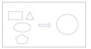
Circle being the simplest shape, easiest form of calculations come around while dealing with circular cross sections. When fluid flows through a non-circular duct, we convert the cross section to circular for convenient calculations. This newly derived diameter of circular cross section is called as hydraulic diameter. It is denoted as Dh. Hence, we can find the same results for a non-circular duct as circular duct by using the concept of hydraulic diameter.

Hydraulic diameter equation

Hydraulic diameter can be found using the formula given below-

Dh = 4A/P

Where,
Dh is hydraulic diameter
A is area of non-circular cross section
P is the wetted perimeter of non-circular cross section

Hydraulic diameter is a function of hydraulic radius Rh, which can be found by dividing area of cross section, A by wetted perimeter, P.

CodeCogsEqn

Note that Dh = 4Rh

This relation is different from the conventional relation between diameter and radius (i.e. D = 2R). This difference arises only while converting non-circular cross sections to circular.

Note- Law of conservation of momentum is satisfied while calculating the hydraulic diameter. Also, hydraulic diameter is not same as normal diameter. Dh is same only for circular conduits.

hydraulic diameter
Simple representation of hydraulic diameter

Hydraulic diameter and Reynold’s number

Reynold’s number is used in fluid mechanics and heat transfer to find the type of flow, laminar or turbulent. Hydraulic diameter is used in the formula to calculate Reynold’s number.
Reynold’s number is the ratio inertia forces to viscous forces. It is a dimensionless number named after Irish scientist Osborne Reynolds who popularized this concept in 1883.

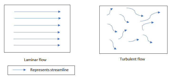
This number shows the effect of viscosity in controlling the velocity of flowing fluid. A linear profile of viscosity is developed when the flow is laminar. In Laminar flow, the fluid flows in such a way that it appears as if it was flowing in parallel layers. These layers do not intersect each other and move without any disruption in between them. This type of flow usually occurs at slow speeds. At slow speeds, mixing of two layers doesn’t take place and fluid flows in layers stacked above one another.

Laminar flow helps us to measure the flow of highly viscous fluids as this type of flow gives a linear relationship between flow rate and pressure drop. Favorable conditions for laminar flow is high viscosity and low velocity. At greater speeds, the fluid particles start behaving in a different manner resulting in mixing of fluid layers. Such mixing gives rise to turbulence and hence the name turbulent flow. Turbulent flow is desirable when proper mixing of fluid is required. One such example is mixing of fuel with oxidizer in rocket engines. Turbulence helps in thorough mixing of fluid.
Reynold’s number can be calculated from the equation given below-

                                                            CodeCogsEqn 3

Where,
Re is Reynold’s number
u is mean speed velocity (in m/s)
ν is kinematic viscosity (in m2/s)
Dh is hydraulic diameter (in m)

In a circular pipe,
Laminar flow, Re < 2000
Transient flow, 2000 < Re <4000
Turbulent flow, Re > 4000

For a flat plate,
Laminar flow, Re <5,00,000
Turbulent flow, Re > 5,00,000

Laminar flow and turbulent flow

Hydraulic diameter of circular pipe | hydraulic diameter of cylinder

Circular pipes are most commonly used pipes for transporting fluid/gas from one place to other (even for large distances). Water pipelines are real life example of circular ducts that are used for transporting fluid. These pipes can carry large distances such as from water filter stations to homes as well as short distances such as ground water tank to terrace water tank. The hydraulic diameter of circular pipe is given by-

Dh = 4πR2/2πR = 2R

                                                                      
Where,
R is the radius of circular cross section.

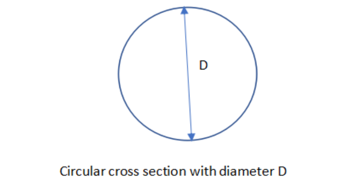
Circle

Hydraulic diameter of rectangular duct

Rectangular ducts are used when spacing is an issue. Moreover, rectangular ducts are easy to fabricate and reduce pressure loss. Air conditioners use rectangular ducts to avoid pressure losses. The hydraulic diameter of rectangular duct is given by-

Dh = 4ab/2(a+b) = 2ab/ a+b

                                                                         
Where,

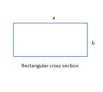
a and b are the lengths of larger and shorter sides.

Rectangle
For square cross section,

a = b

Dh = 2a2/2a = a

Where,
a is the length of each side of square.

Hydraulic diameter of annulus

Sometimes, to increase/decrease the rate of heat transfer, two fluids are passed through an annular tube such that one fluid flows outside the other. heat transfer rate is affected by the action of two fluids. Hydraulic diameter of annulus is given by-    

gif

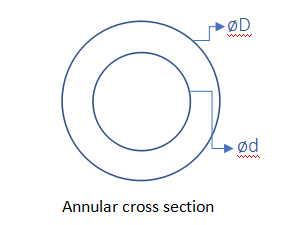
Where D and d are diameters of outer circle and inner circle respectively.

Annulus


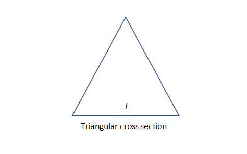
Hydraulic diameter of triangle

gif

Where,
l is the length of each side.

Triangular cross section
                                                   

Hydraulic diameter of ellipse

Dh = 4wh(64-16e2)/w+h(64-3e4)

Where, e= w-h/w+h

Hydraulic diameter of plate heat exchanger | hydraulic diameter of shell and tube heat exchanger

Heat exchangers are thermal devices used for transferring heat from one fluid to other in order to decrease/increase the temperature of fluid as desired. Many types of heat exchangers exist out of which most commonly used are plate and shell tube heat exchangers. Fluids can be passed through the heat exchanger in two ways. In first type, both hot and cold fluids are injected in the same direction hence, it is called as parallel flow heat exchanger. In second type, fluids are passed through the tube in opposite directions hence it is called as a counter flow heat exchanger.

Based on this, evaporator and condenser are designed. In evaporator, the hot fluid’s temperature remains same while the cold fluid gets warmer. In condenser, the temperature of cold fluid remains same and hotter fluid’s temperature decreases.

The rate of transfer in heat exchanger is given by following relation-

For hot fluid: Qh = mh Cph (Thi – Tho )
For cold fluid: Qc = mc Cpc (Tco – Tci )

By conservation of energy,
Heat lost by hot fluid = heat gained by cold fluid.
=> Qh = Qc

Where,
Qh denotes heat lost by hot fluid
Qc denotes the heat gained by cold fluid
Thi is the temperature of hot fluid at inlet
Tho is the temperature of hot fluid at outlet
Tci is the temperature of cold fluid at inlet
Tco is the temperature of cold fluid at outlet
mh is the mass of hot fluid (in Kg)
mc is the mass of cold fluid (in Kg)
Cph is the specific heat of hot fluid (in J/K-Kg)
Cpc is the specific heat of cold fluid  (in J/K-Kg)

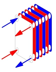
In plate heat exchangers, heat cuts through the section and separates hot and cold fluids. This type of heat exchanger is used in many industrial applications. They are used in heat pump, oil cooling systems, engine cooling system, thermal storage systems etc.
Plate heat exchanger has a rectangular/square cross section hence, hydraulic diameter is given by-

                                                                        Dh = 2ab/a+b            

Where,
a and b are lengths of shorter side and longer side respectively.

Plate heat exchanger 2
Plate heat exchanger
Image credits: https://commons.wikimedia.org/wiki/File:Plate_frame_1.svg

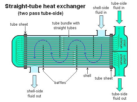
In shell and tube type heat exchanger, tubes are installed in a cylindrical shell. Both hot and cold fluids are passed through these tubes in such a way that one fluid flows outside the other fluid. Due to this, heat is transferred from one fluid to another. Shell type heat exchanger is widely used in industries mainly in chemical processes and applications where high pressure is needed.
Shell tube heat exchanger has annular cross section hence, hydraulic diameter is given by

                                                                               Dh = D-d
shell tube
Shell and tube heat exchanger
Image credits: Straight-tube heat exchanger 2-pass

Equivalent diameter vs Hydraulic diameter

Equivalent diameter and hydraulic diameter differ in values. The diameter of circular duct which gives same pressure loss as rectangular duct for equal flow is called as equivalent diameter. Even though circular ducts have least surface area for given pressure loss, they are not suitable for fabrication. Rectangular ducts are easy to fabricate hence they are used in practical cases. When flow rate and pressure drop is known, then to design a rectangular duct, we use friction chart to find the equivalent diameter and then required dimensions by fixing certain parameters like aspect ratio or length of any one side.

The ratio of length of shorter side to longer side is called as aspect ratio.

AR = a/b
                                                               

We can find equivalent diameter by Huebscher equivalent diameter equation. It is shown below-
                   De = 1.30 (ab)0.625/(a+b)0.25

Where,

a and b are length of shorter side and longer side respectively.

Recent studies have concluded that equivalent diameter being derived from empirical relations, is not reliable while calculating pressure losses in pipes. Hence, we use hydraulic diameter in all cases.

What is the difference between hydraulic diameter, equivalent diameter and characteristic length in fluid mechanics and heat transfer?

Hydraulic diameter, as discussed earlier, is the newly derived diameter from a non-circular duct such that the flow characteristics remain same. Hydraulic diameter is used for calculating Reynold’s number which helps us to understand whether the flow is laminar, transient or turbulent.

The diameter of circular duct which gives same pressure loss as rectangular duct for equal flow is called as equivalent diameter.

Pressure loss in a pipe is given by Darcy-Weisbach equation-  

gif

Where,

ρ is the density of the fluid (kg/m^3)
D is the hydraulic diameter of pipe (in m)
l is the length of pipe (in m)
v is the mean flow velocity (in m/s)Characteristic length is basically volume of a system divided by its surface area.
It can be equal to hydraulic diameter in some cases.

Mathematically,

Lc = Vsurface/Asurface

For square duct-
Lc = a

For rectangular duct-

Lc = 2ab/a+b

In heat transfer, characteristic length is used for calculating Nusselt number.The ratio of convective heat transfer to conductive heat transfer is called as Nusselt number. It shows what type of heat transfer dominates.
Nusselt number, Nu is given by-

Nu = hLc/k

What is the difference between hydraulic radius and hydraulic depth / hydraulic mean depth?

There is a misconception that hydraulic radius and hydraulic depth are same. They both have different meanings and hold individual significance while measuring fluid properties. The concept of hydraulic radius and hydraulic depth is discussed in detail below.

The ratio of cross sectional area of flow to the wetted perimeter is called as hydraulic radius.
Rh = A/P

The ratio of cross sectional area of flow to free water surface or top surface width is called as hydraulic depth.

Hd = A/T

where,

A is the cross sectional area of flow
T is the width up to top surface or free surface.

Mathematically, hydraulic mean depth and hydraulic radius are same.

What is the physical significance of hydraulic diameter in fluid and thermal sciences?

Practically, Reynold’s number is used to check the behaviour or nature of the fluid flow. This in turn helps us in finding Nusselt number which is then used to find the rate of heat transfer from the closed conduit.
Hence, Reynold’s number is a very important dimensionless number which plays a vital role in both fluid and thermal sciences. But to find Reynold’s number, first we need to find hydraulic diameter of the closed conduit. For non-circular cross sections, hydraulic diameter provides a value of diameter such that its flow characteristics are equivalent to that of a circular cross section.

The ratio of convective heat transfer to conductive heat transfer is called as Nusselt number.

Nusselt number is given by following relation-

For laminar flow: Nu = 0.332 Re0.5 Pr0.33
For turbulent flow: Nu = 0.039 Re0.8 Pr0.33

Where,
Re denotes Reynold’s number
Pr denotes Prandtl number

The ratio of momentum diffusivity to thermal diffusivity is called as Prandtl number. It is named after German scientist Ludwig Prandtl. This dimensionless number helps us in calculations related to forced and natural heat convection. Its significance is that it helps us to study the relation between momentum transport and thermal transport capacity of fluid.

Prandtl number is calculated by the formula given below-

Pr = μCp/k

Where,
Pr is Prandtl number
µ is dynamic viscosity
Cp is specific heat

Note that Nusselt number can also be found using the relation: Nu = hLc/k, when we know the values of convective and conductive heat resistances.

In simple words, hydraulic diameter forms the basis for finding the behaviour of flow and rate of heat transfer from the fluid that is flowing in a closed conduit. With that, it also brings us easy calculations by converting a non-circular conduit to a circular one.

Scotch Marine Boiler: 7 Important Facts You Should Know

Content

What Is a Scotch Marine Boiler?

A Scotch Marine boiler is an example of a fire tube boiler wherein the flue gases flow through tubes that are placed in a tank of water. The Scotch Marine boiler has adapted its working principle from the Lancashire boilers which consist of numerous furnaces to increase the heating capacity. Two main differences set Scotch Marine Boiler apart from Lancashire boilers and they are

  • Scotch Marine boilers are made up of multiple fire tubes to increasing the heating capacity per cross-sectional area
  • Scotch Marine boilers are half the size of Lancashire boilers as the path for the flue gas to flow has been packed in the available location.

Scotch Marine Boiler Design

A Scotch Marine boiler is a fire tube boiler that is used in ships. The boiler is shaped like a horizontal cylinder with furnaces at the lower portion of the boiler. Above the furnace, there are many fire tubes. The heat and smoke from the furnace flow to the boiler. The fire tubes have a capping at the end which is known as a smoke box on the outer surface of the boiler shell.

Scotch Marine Boiler Parts

The Scotch Marine Boiler consists of the following parts which are

  • A Furnace: The space below the boiler is where the furnace is located. A boiler with a single end is usually equipped with four furnaces. The furnaces are corrugated for strength, and they have separate combustion chambers for each furnace.
  • A Combustion Chamber: This is the area below the shell of the boiler where the fuel is burnt to generate steam from the water. This chamber is made up of four layers of plates which are top plate, backplate, tube plate, and two-sided plates.
  • A Smoke Box: This unit has several tubes packed together horizontally and connects the combustion chamber and the chimney. The flue gases from the combustion chamber pass through these tubes.
  • A Chimney: It is used for releasing the flue gases from the combustion chamber into the environment.
  • A Boiler Shell: This part of the boiler consists of cylindrical plates which are welded together to contain sufficient water and steam. The layout also helps in protecting the inner parts of the boiler. The fitting of the boiler is usually attached to the boiler shell.

Scotch Marine Boiler Diagram

Image Credit: Image from page 1026 of “Canadian forest industries 1901-1… | Flickr

Scotch Marine Boiler Working

Scotch Marine boilers can be single-ended or double-ended. A single-ended boiler is usually composed of somewhere between one to four furnaces while a double-ended boiler has furnaced on either end of the boiler with somewhere between two to four boilers. It is equipped with a horizontally placed drum which is about 2.5 to 3.5 meters in diameter.

The water that passes through the tubes is heated by the flue that is burned in the combustion chamber of the furnace. The flue gases which are produced from the burning of fuel passes on the outer surface of the tubes to the chimney. This adds additional heat to the tubes thereby providing faster steam generation and better quality of steam. The flue gases are then released into the environment through the furnace

Advantages of Scotch Marine Boiler

The main advantages of Scotch Marine Boiler are as below:

1. The shell of these boilers is large which makes it easy for blowdown and water treatment processes.

2. The working fluid for this type of boiler is primarily water of any type not necessarily purified or distilled water.

3. This type of boiler has high efficiency making it suitable for heavy load.

4. The cost of construction is minimal as it does not require a brickwork model or any external flues.

Disadvantages of Scotch Marine Boiler

The main disadvantages of Scotch Marine Boiler are as follows

1. This type of boiler cannot easily control the variations in load.

2. The steam quality is not comparable to water tube boilers

3. They require larger floor space depending on the load that needs to be handled

4. The diameter of the boiler is the reason why the pressure from this type of boiler cannot exceed 300psi.

Frequently Asked Interview Questions and Answers

1. How does a scotch marine boiler work?

The working principle of a scotch marine boiler is simple. The fuel that is used to heat the water will be burnt in a combustion chamber. The fuel is fed to the combustion chamber through a fire hole. Through the convection heat transfer process, the heat produced by burning the fuel is transferred to the water in the chamber surrounding the combustion process.

The water is then converted into steam and supplied to the steam turbine. The flue gases that were produced during the combustion process are released into the environment via the smoke tube into the boiler chimney. Here, water carried away the heat in the exhaust gases passing through the smoke tubes

2. What are the types of boilers?

Several types of boilers are used in the industries. A list of the commonly used boilers are jotted down below:

  • Shell and Tube boiler
  • Lancashire boiler
  • Locomotive boiler
  • Wet Back Boilers
  • Dry Back Boilers
  • Cornish Boiler
  • Scotch Marine Boiler
  • Packaged Boiler
  • Reversal Chamber
  • Two-Pass Boiler

3. Which is better fire tube boiler or water tube boiler? | Between fire tube and water tube boilers which has more advantages and why?

Among, the two types of boilers i.e., the fire tube boiler and the water tube boiler, the water tube boiler is more efficient than the latter due to the following reasons

  • The amount of water that is used in the water tube boiler is comparatively lesser than the amount used in a fire tube boiler which in turn results in the quicker generation of steam and less fuel requirement in the case of the water tube boiler.
  • Since they require less amount of water for the boiling process, the design of the boiler is compact and environmentally friendly.
  • They respond quickly to changes in load i.e., need of steam. Units that are configured in terms of modules can be charged up and down depending on the required amount of steam.
  • Their increased efficiency and excellent performance are also attributed to their ability to last longer in comparison to their counterpart.
  • It is safer to operate a water tube boiler in comparison to a fire tube boiler as they are internally fired.
  • They occupy small floor space and are usually used in large power plants because of their efficiency and higher steam production.

4. What improvements did the Yarrow Water Tube Boiler have over the Scotch Marine Boiler?

The Yarrow Water Tube Boiler was built with a different concept of working than the Scotch Marine Boiler. A Scotch Marine boiler produces large volumes of steam which is at low pressure. On the other hand, a Yarrow Water Tube Boiler was built to produce fewer volumes of high-pressure steam. It is difficult to compare the merits and demerits of these two types of boilers.

A Yarrow Water Tube boiler is usually used for marine applications with a newly installed turbine not because of the high pressure it produces but also because of its compact sizing and limited maintenance that is required for it to work. While Scotch Marine boilers are often installed in equipment with piston technology which had to undergo timely repair and involves high maintenance.

5. Can anyone explain to me about marine boiler and types of marine boiler

Marine boilers are used for marine applications, whereby the heat produced by the fuel is used for running the ship. The working principle of a marine boiler is to change the state of fluid from liquid to vapor. The temperature of the fluid in the boiler is transformed from liquid to vapor in an enclosed vessel to avoid loss of energy into the surrounding. The heating is carried out in furnaces to ensure that heat is transferred to the operating fluid.

There are two main categories of marine boilers which are

  • Water Tube Boilers
  • Fire Tube Boilers

6. What is the function of a pressure gauge in a boiler?

The primary function of a pressure gauge in any type of boiler is to indicate the pressure build-up inside the drum of the boiler which is often represented as kN/m2.

7. What are stay tubes in a boiler?

In a fire tube or water tube boiler, stay tubes provide support and stability to the endplates and the normal tubes. The stay tubes have a greater wall thickness and strong construction to withstand the high surrounding temperature. They have a greater diameter and are welded to the plates on both the upper well as the lower region. The steam is collected in a region made up of shell-like structures and an internal cone.

8. Why are fire tube boilers not suitable for high pressures?

Fire-tube boilers require large volumes of water due to which the steam pressure is produced after a long time. Since both steam and water are contained in a single vessel, the pressure of the steam produced by this type of boiler is not very high and not very dry.

9. What are the different types of water tube boilers and fire tube boilers?

The different types of water tube boilers used in industries are as follows:

  • Sterling boiler
  • Simple Vertical Boiler
  • Babcock and Wilcox Boiler

The different types of fire tube boilers used are as given below:

  • Immersion Boiler
  • Scotch Marine Boiler
  • Cochran Fire Tube Boiler
  • Lancashire Boiler
  • Cornish Fire Tube Boiler
  • Locomotive Boiler

10. Why are economizers used in boilers?

Economizers are devices used in boilers that use the heat from exhaust gases to preheat the cold water entering the boiler. They are heat exchangers aimed at increasing the temperature of the fluid beyond its boiling point and thereby reducing energy used.

There are other types of boilers such as Benson Boiler, Cochran Boiler, Babcock and Wilcox boiler, and AFBC boilers that are widely used in the industry