How To Solder a Gate Valve: The Correct Way and Solved Problems and Facts

pic 1 1 300x146 1

Gate valves are generally made for shut-off, and you find them in almost all plumbing applications from industrial to water supply at home or in gardens.

Needless to say, the same applies for home fluid plumbing as well. To solder a Gate valve following steps are to be followed:

  • For smooth functioning and cost-effectiveness of the fluid pipelines, proper soldering of a Gate Valve is mandatory.
  • Ensure that the whole piping system is free of any fluid(or water in case of home plumbing) by closing the main valve and draining the residual fluid.
  • Before you start the soldering job, ensure the valve is in close condition.
  • Measure the length of the Gate valve accurately because that much portion of the pipe has to be cut (generally ½ to ¾ inch depending upon the size of the valve and piping)
  • Next, using a pipe cleaner, clean the main pipe as well as the Gate valve. The ends of the pipe must be free of dirt. Cleaning the inside of the pipes is as important.
  • Using a flux brush apply some paste flux on both the ends of the main pipe and along with the Gate valve.
  • Now insert the cut ends of the main pipe inside the Gate valve properly. Some resistance should be expected.
  • For the final step, get the solder wires. Using a propane torch heat both the ends to be soldered. Keep the bent end of solder wire near the adjoined area so that it melts around it properly. Same process is applied for the other end also.
  • Allow to cool down the soldered ends and remove the excess amount with the help of a rag.
  • The Gate valve is now fixed in the piping system.

Do you Solder a Gate Valve open or closed

Generally, each manufacturer has a recommendation for open or closed state of the Gate valve at the time of soldering.  Therefore, it is beneficial to go through the manufacturer’s guidelines before starting the work

As per the experts’ opinion Gate valve should remain in a closed state at the time of soldering. Gate valves are most widely used in industrial sectors for starting or stopping a flow. Gate Valves are not suitable for regulating service.

Before installation of a Gate valve, detailed verification of operating fluid, environment, pressure, and temperature are necessary. The installer should ensure the limit of pressure and temperature that may be sustained by the Gate valve.
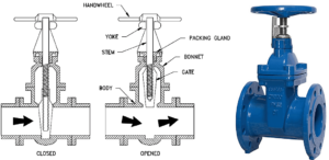
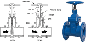
  •  
solder a gate valve

Image credit: Gate valves https://hardhatengineer.com/gate-valve-types-parts/

How do you Solder a copper gate valve?

The soldering flux paste used for copper soldering is Superior No.135 (rosin/petrolatum). This flux provides protection to the soldering area and is ideal for copper soldering.

The basic steps of soldering copper gate valve are as follows:

  • Collect all the necessary tools at one place like a propane torch for heating. Arrange tinning flux or paste flux and lead-free solder.
  • Cut the pipe with a tube cutter.
  • By inserting and twisting a reaming attachment, the inside burrs at the cut ends of the pipe can be removed.
  • Clean dirt and corrosion from the outside pipe surface with an emery cloth.
  • Inside portion of the pipe should also be cleaned using a wire brush.
  • Brush an even layer of flux over the pipe surface and inside the valve, the same way as you apply butter on a toast.
  • Heat the joint with the help of a propane torch evenly and allow itthe solder to meltso that it flows into the joint and seal it. A full joint on all sides should be obtained.

How do you Solder a brass gate valve?

The main difference between copper and brass is that brass requires much more heat for the solder to work efficiently.

As an alloy of copper and zinc, Brass is companionable with copper. Solder adheres to copper as well as brass properly, and fittings are generally molded with slip joints and can be easily soldered to the pipes.

More often than not, you would encounter a brass valve while looking for a valve to solder in a copper pipe. The amount of heat required to melt the flux inside a brass valve is around 5-6times that of a copper valve. Hence, in order to ensure that the flux has properly set in between the piping and the valve, sufficient time must be provided for heating.

What position should a gate valve be is to be soldered?

Gate valves are suitable for all types of applications, both above-ground and underground installations.

Most convenient position for all models of Gate valves (inclined, horizontal, and vertical) with the flow in both directions is installed horizontally with the hand wheel pointing in the upward direction.

The position should be selected in such a way so that it can be easily accessible during operation, inspection, and maintenance. A horizontally placed Gate valve is always easy to operate and also easily accessible for maintenance. However, there are some industrial applications where installing a Gate valve vertically downward is preferred. This is to ensure that the valve remains in an open position, even if the lock-nut holding the gate to the spindle has broken and the gate has fallen off.

How to Solder a ball valve?

Soldering a ball valve is a very familiar and frequently used project in plumbing. The soldering technique of ball valves is not a complex process and can be performed without any professional guidance.

To perform correctly, one should have proper knowledge of the whole process. The step by step process for soldering a ball valve is as follows.

  • Assemble all the necessary tools like tinning flux, lead-free solder, a ball valve, pipe cutter, pipe cleaner, heat source, safety gloves, etc
  • Cut the pipe with the help of a pipe cutter and clean the two ends thoroughly.
  • Apply a layer of flux with the help of a brush on the two pipe ends and inside the ball valve also.
  •  Place the ball valve in between the cut ends of the pipe,
  • According to the manufacture’s guidelines, keep the ball valve in the open or closed position during soldering.
  • Apply heat to the pipe and ball valve area. It is important to note that the body of the valve should not come under direct fame as otherwise, the nylon seal inside the valve may be melted.
  • Apply the solder on adjoined areas and continue heating until the solder melts and fills up the gap.  Let the pipe cool down.
  • One of the most commonly asked questions is whether to solder ball valves in an open or closed position.Both open and closed option is suitable for soldering ball valves. But it is advisable to solder ball valves in a closed position to avoid the chance of formation of blowing gas bubbles in the joint.
  • In the closed position, air generally exits the pipe. On the contrary, there are certain risks involved in soldering a ball valve in an open position. In the open position, water may be trapped in the seals or pipes, which get convert into steam due to the application of heat during soldering. Steam may blow out the seal causing damage to the valve.
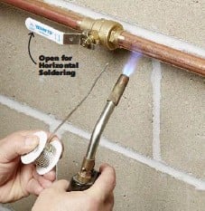
ball valve

Image Credit: Soldering of Ball valves https://www.pressreader.com/usa/the-family-handyman/20180501/282437054662433

Can I Solder a closed ball valve with water on the other side?

Soldering a closed valve with water on the side is beneficial.

It is possible to solder a ball valve with one side in live condition. The application of heat during soldering should not be too high to melt the seals. Otherwise, it may result from a bleeder port. Wrapping a wet rag is always suggested for better results.

To remove the heat produced during soldering, it is normal practice to wrap a wet cloth to remove the heat away. If water is present on the other side, it is beneficial as it will help to remove the heat generated by the soldering process. Care must be taken so that you don’t heat the side with water as it might lead to vaporization of water leading to the blow-up of the ball valve seal.

Can you Solder near Teflon tape?

Teflon tapes or PTFE (Polytetrafluoroethylene) is a common name in plumbing, most widely used for sealing pipe threads. Breakdown may occur in contact with open flames.

The applicable temperature range of a Teflon tape ranges from -268°C to+260°C. Generally, a Teflon tape can withstand temperatures upto 260°C, rate of decomposition is slow up to 400°C. During Soldering near PTFE tape, this temperature range should be maintained.

What is used in Soldering?

Soldering is a joining process most widely used in manufacturing electronic equipment, joining and sealing pipes in the plumbing trade, and also in the jewelry business.

The list of essential items required for any kind of Soldering process are:

  • Solder: The main ingredient of the Soldering technique melts to join different types of metals. Traditionally an alloy of tin and lead (Sn 60% & Pb 40%). Nowadays, due to lead toxicity, most of the solders are lead-free, which is an alloy of tin with other metals like copper and silver.
  • Soldering Iron: It is a handheld tool that is the main source of heat to melt the solder. Generally, it has a pencil-like shape and very comfortable and easy-to-handle tool. As per the requirement, it may also be available as larger solder guns.
  • Soldering Flux:To achieve a good solder joint, a fresh and proper chemical flux is essential. Flux removes oxides from both the metal surface and solder surface so that molten solder can wet the clean metal surfaces to be joined. Resin, Organic, and Inorganic are the different types of flux used as per the requirement.

Soldering valve to copper pipe

Soldering a valve to the copper pipe can be tricky or an easy task at the same time.

The basic steps and precautions that are to be taken for proper soldering of a valve to a copper pipe are as follows:

  • The workmanship of an effective Copper pipe soldering depends largely on sticking to the basics, which are: – right preparation, right tools, and rights methods
  • Get all your tools in places like the flux paste, the propane torch, the solder, a piece of sandpaper, the pipe cutter, and of course, the valve and the pipe.
  • If the soldering is in a live line, ensure the line is drained properly and the source of inlet water is isolated. Then cut the pipes with the pipe cutter.
  • Once the pipes are cut, it is necessary that the surfaces at both ends of the cut pipe are properly rubbed with the abrasive sandpaper so that a shine appears over the surfaces to be soldered.
  • The next step is to dry-fit the valve, and it is to be ensured that the valve fits into both sides snugly.
  • Apply the flux properly on both the surface as you apply butter to a toast!!! And install the valve.
  • Before you start heating, ensure the valve is at least partially open. This is done so that if there is any residual water left in the pipe, it doesn’t pressurize the system and crack the soldered joints.
  • Lit up the propane torch to heat the surface to melt the flux within.
  • Once the flux has melted, the primary sealing is done. The next step is to bring in the solder.
  • Continue heating with the propane torch to melt the solder so that it is assimilated into the gap between the pipe and the fitting, thus providing a leak-proof fitting.
  • Once it is ensured that the solder has got into all the cracks and crevices of the fitting, let it cool down before being put into service. This is to ensure that the newly soldered joint does not crack due to thermal shock.

How to Solder brass valve to copper?

It is not a big deal to solder brass valve to copper pipe if we are aware enough about certain facts. The temperature of the pipe should be hot enough at the time of applying the Solder.

It is advisable to perform soldering of brass valves correctly in the first attempt because redo may create the problem. When the metal surface reaches the accurate temperature, the plumbing solder flows into the joint between the pipe surface and valve by capillary action and, after cooling, results in a watertight seal.

To avoid a leaking joint, make sure that the moisture inside the pipe can escape completely when it turns into steam.

The same steps are followed as discussed above for soldering valve to copper pipe.
Saturated Liquid Water: Need to Know Critical Facts

picture 300x246 1

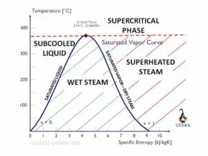
If we consider the phase diagram of a pure substance such as that of water, the Saturated Liquid water Line and Saturated Vapor Line divide the whole phase diagram into three distinct regions.

A pure substance undergoes state changes as per the variation in temperature, pressure, and volume of the substance. The solid line which separates compressed or sub-cooled liquid from the saturated mixture of vapor and liquid is known as Saturated Liquid Line.

The saturated liquid line denotes the phase change of a substance from liquid to vapor. Below the saturated liquid line, the substance is in pure liquid form, and above it is in partial vapor form till enough heat is added to convert it to 100% vapor.

For a laymen water boils at 100 °C and hence the water is considered saturated at that temperature. The above statement would hold true when water is being heated at atmospheric pressure at sea level. However, if water is heated at a higher elevation (like in a mountain top) or in an enclosed pressurized enclosure (like in a boiler), it would start boiling at different temperatures. In other words, water attains saturation state at different temperatures at different system pressures. Thus, a combination of various temperature and pressure values at which water exists in its saturated form defines the saturated liquid line for water.

Properties of Saturated Liquid Water

If water exists in its liquid state at its saturation temperature and pressure, it is known as a saturated liquid or saturated liquid water.

Water or, for that matter, any liquid tends to lose its saturation state as its temperature is increased or its pressure decreases.

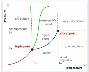
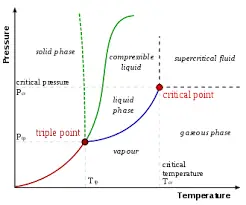
Saturated liquid water is defined by a thermodynamic state specified by its temperature and pressure sets. Water exists in a saturated liquid state from temperatures ranging from 0 deg C to 374 deg C with corresponding Saturation pressures ranging from 0.006 bar to 200.9 bar. At temperatures beyond 374 deg C or pressures beyond 200.9 bar, water exits in both liquid as well as vapor form. These temperature and pressure numbers define what is called the Critical point of liquid water.

On the other hand, at a temperature below 0 deg C, water exists either as solid ice or coexists as a mixture of liquid water and solid ice.

Saturated water becomes sub-cooled as pressure is increased beyond its saturated state. The different states of water are shown by in the following graph:

Saturated liquid water
Image Source: The liquid–vapor critical point in a pressure–temperature phase diagram is at the high-temperature extreme of the liquid–gas phase boundary. The dotted green line shows the anomalous behavior of water.https://en.wikipedia.org/wiki/Critical_point_(thermodynamics)

The Density of Saturated Liquid Water

If we consider  compressible fluid like gases, the density increase with the decrease in temperature and increase in pressure. The liquid is termed an incompressible fluid, so the impact of pressure in densities is minimal, but the temperature does have some impact.

To keep liquid water in a saturated state as the temperature is increased, pressure must be increased. Thus, although minimal, the impact of the decrease in density due to the rise in temperature is partly countered by an increase in respective saturation pressure.

Saturated liquid water at 0.01 deg C has a density of 999.79 kg/m3. The corresponding pressure is 0.006 bar. At a temperature of 100 deg C, the density is 958 kg/m3. The corresponding pressure is 101.42 bar. This indicates as the temperature is increased, saturated liquid water densities too decrease.

Enthalpy of Saturated Liquid Water

Enthalpy is the sum of internal energy and PV work done.

The internal energy of a compound is dependent on its temperature and so its Enthalpy.

If the temperature of a substance increases, the kinetic energy of the molecules also increase resulting in an increase in its internal energy. The PV work done with increased temperature is nil. Thus,the overall enthalpy impact with an increase in temperature is the same as the impact on internal energy with increased temperature.

Saturated Liquid Water Table

The saturated liquid water table includes temperature and pressure set points at which water exists in a saturated liquid state.

By saturated liquid state, it implies that the addition of a small amount of heat to it would lead to vaporization of water. A standard saturation table for water represents the density, Enthalpy, entropy, and specific volume at the corresponding temperature and pressure values.

The saturated liquid water table starts with a temperature of 0.01 °C with corresponding saturation pressure of 611 MPa or 0.006 bar. The corresponding Enthalpy is 2500.9 Kj/kg, and entropy is 9.1555 KJ/Kg.K, density is 999.79, and specific volume of 1.00021 m3/Kg.

As the temperature increases in the saturated water table, the corresponding pressure increase to keep water in a saturated liquid state. With the rise in temperature, the density decreases and also there is an increase in its specific volume. The Enthalpy increases due to an increase in internal energy, while on the other hand, the entropy decreases.

These tables can be generated via software such as WASP® and online calculators such as one available at https://www.spiraxsarco.com/resources-and-design-tools/steam-tables/saturated-water-line for various temperatures. Saturated water tables are also available at sites such as https://www.cambridge.org/br/files/9813/6697/5550/Appendix_B.pdf.

Saturated Refrigerant: Need to Know Critical Facts

Images 300x226 1

What is saturated refrigerant

The temperature of “saturation” is calculated by identifying the observed pressure on the P-T card and measuring the temperature associated with it.

If you can accurately detect temperature at one of these three locations, P-T link is used to determine the “saturation” pressure by identifying the pressure that corresponds to the reported temperature. The refrigerant within vapour/liquid state is known to be the refrigerant kept in the condenser or evaporator coils.

It is only relevant when utilising your PT chart like a troubleshooting tool. The refrigerant is said to be saturated when it exists in both a liquid and a vapour state.

What does saturated mean in HVAC

By detecting the measured pressure on the P-T card and measuring the temperature associated with it, the temperature of “saturation” is computed.

In the HVAC/R industry, the term “saturated” or “at saturation” refers to refrigerant which is in the process of transitioning from liquid to vapour in the evaporator or vapour to liquid in condenser.

It is required to check a series of gauges or use a PT (Pressure-Temperature) table to determine the temperature that corresponds to a specific refrigerant and pressure. This is referred to as the saturation temperature.

How do I know if my refrigerant is saturated

The saturation temperature of a refrigerant is the temperature at which it transitions from a liquid to a gaseous state.

The “saturation” temperature is determined by locating the measured pressure on P-T card and measuring the related temperature.

This also means that if you can properly measure temperature at either of these three sites, you can use the P-T
connection to identify the pressure that corresponds to the reported temperature and calculate the “saturation” pressure.

What is saturated refrigerant temperature

The refrigerant’s saturation temperature is the temperature at which it transforms from a liquid to a vapour state. Its boiling point is the same as its saturation temperature.

When the superheat is too low, the evaporator outlet is extremely close to the point where all the refrigerant is finally evaporated. If this happens, liquid refrigerant may be forced back into the compressor, causing significant damage.

The liquid refrigerant gets completely evaporated much before it enters the evaporator outlet whenever superheat is too high.

As a result, the refrigerant’s vapour temperatures keeps rising, thus increasing the heating rate of the gas in the vapour line to the compressor through the evaporator. The saturation temperature of seawater is 212 degrees Fahrenheit. As pressure rises, a liquid’s saturation temperature rises with it.

Read more about Superheat Refrigeration

Saturated refrigerant table

Any engineer operating with the refrigerant requires a saturated refrigerant table.

It’s commonly used to calculate saturated refrigerant temperature from pressure, or vice versa, that is, pressure from saturated refrigerant temperature. These tables frequently include other relevant data like specific volume (v) and specific enthalpy (h) in addition to temperature and pressure.

Saturated refrigerant vapour

There are refrigerant conditions in addition to refrigerant states and pressure. Superheated, saturated, or subcooled are some of the conditions which enables the existence of a refrigerant.
Condition of saturation: Saturation is usually discussed in terms of temperature. The saturation temperature is the point at which a fluid transitions from vapour to liquid or vice versa. At their saturation temperatures, liquid and vapour are referred to as saturated liquid and saturated vapour, respectively.

Saturated Refrigerant
Saturation- Boiling point

Since phase shifts involving both vapour and liquid states, saturation would occur in both the condenser and evaporator. The liquid is at its peak temperature for that respected pressure, while the vapour is at its lowest temperature for the given
pressure at the time of saturation. However, at a particular pressure, both vapour and liquid are at same temperature at the saturation point.

What is evaporating temperature in refrigeration

To move heat from one medium to another, the refrigeration cycle requires a fluid known as a refrigerant. We normally think of such cycle as producing cooling, but if you’ve ever touched the rear of an air conditioner or a refrigerator, you’ll know it also creates heat.

This is particularly the case of a heat pump, that is essentially an air conditioner with the ability to switch between cooling and heating modes. The evaporator’s refrigerant “evaporates,” as the name implies. The temperature of the liquid refrigerant is somewhere between 35°F and 55°F as it enters the evaporator.


When it changes state to vapour from liquid, then it absorbs the heat without altering the temperature. Warm, humid indoor air is forced across the evaporator coil, which generates heat. This gives off most of its heat as by flowing that over the cooled coil helps the moisture to condense. A fan circulates the cooler, dryer room air back into the cooled chamber.

Saturated refrigerant condensing temperature

Subcooling is when the condenser outflow temperature is lower than the saturation temperature. There would usually be a separator, maybe a receiver, sight glass, as well as some plumbing between the evaporator intake and the condenser outlet.

All of these factors will result in a decrease in pressure. If the system did not have subcooling, the pressure loss in these things could cause the refrigerant to begin converting back into a vapour before it reaches the evaporator, reducing the evaporator’s refrigeration effect.

Also, because the refrigerant enters the evaporator is also at a reduced temperature, subcooling improves the system’s efficiency by a modest amount. Saturated condensing temperature is the temperature at which the vapour state of a refrigerant change to its liquid state.

Saturated refrigerant evaporating temperature

In this section, we are going to discuss about the saturated refrigerant evaporating temperature.

Before changing into a vapour in the evaporator, the refrigerant accumulates a lot of heat. This is known as latent heat, since it does not affect the temperature of the liquid refrigerant; instead, the heat is absorbed until vaporisation occurs.

Refrigeration is made possible by absorbing the latent heat and simultaneous rejection in the condenser coil. Saturated condensing temperature is the temperature at which the liquid state of a refrigerant change to its vapour state.

FAQs

Where is saturated refrigerant vapor found?

In this section, we are going to discuss about various locations where saturated refrigerant could be found.

The evaporator, condenser, and receiver are the three sites where there is an existence of saturated refrigerant vapour. These three locations are proven to have a mixture of both refrigerant liquid and vapour. The refrigerant is said to be “saturated” when both liquid and vapour exist in it.

The temperature relationship represented by a P-T card is only effective whenever there is a combination of refrigeration vapour pressure and liquid present; otherwise it cannot be used. It enables the P-T connection in different states of a refrigerant
with a fully running refrigeration / air conditioning system.

Why does refrigerant need to change states?

Coolant gases have had the ability to absorb heat from their surroundings.

A latent heat is the heat energy that causes a cooling fluid to transform into a vapour at a given pressure for a constant saturation temperature. In other words, heat energy that induces a phase transformation of a refrigerant without changing its temperature is known as latent heat.

A form of energy, generally electricity, is being used to push the gas to transition state inside a mechanical refrigeration unit. The air around the gas is affected by this change in condition.

Pipe Elbow Dimensions:Exhaustive Problems Solution and Facts

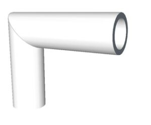
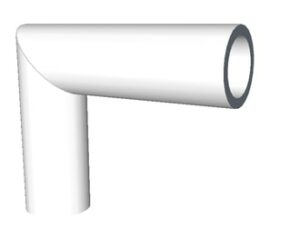
330px Mitre joint pipe 300x247 1

To change the direction of piping, pipe elbows are used. It is important to find pipe elbow dimensions for making a turn of desired radius.

This article discusses about different types of elbows and formulae to calculate their dimensions.

What is elbow in piping?

The path of piping is not always straight, it makes a turn at the end as required.


Elbows are the connectors between two pipes that are inclined at some angle. Elbow contains two openings at a specific angle where the pipes are fixed. Elbows usually come in 90 degrees, 45 degrees or 22.5 degrees.

What is the use of elbow in pipe fitting?

When there is a need to change the direction of fluid flow, the piping system needs to be bent.

This bent cannot be achieved directly by bending the PVC pipe as it is brittle in nature. An elbow is used which connects two straight pipes in angle. This way the direction of piping system is changed and hence the direction of fluid flow.

How do you calculate pipe length elbow?

To calculate the length of the pipe elbow, we need the distance between the ends of two pipes that need to be connected and the angle subtended by elbow.

Lets take an example of 90 degree pipe elbow for which pipe end distance (radius of elbow) is 300 mm.

Circumference of circle is given by-

Circumference = 2πr

90 degree elbow covers 0.25x circumference of circle. Hence, the length of pipe elbow- 0.25 x circumference of circle with radius 300mm.

What is the formula of 90 degree elbow?

Take off is defined as the length of material removed to make the pipe and fitting of a specified length.

The formula for 90 degree elbow is given below-

A = tan(45) x 1.5D X 24.5

Where,

D is diameter of elbow in inch

A is elbow center take off

What is the length of a 90 degrees elbow?

90 degrees elbow makes one quarter of a full circle. To find the length of 90 degrees elbow, we find the circumference of circle and then multiply it by 0.25.

The circumference of circle is given by the formula:

Circumference = 2πr

Hence the length of elbow becomes- 0.25 x circumference

What is the radius of pipe elbow?

On the basis of length of radius, elbows are classified into types- long radius elbow and short radius elbow. 

Radius of curvature is around 1.5 times the nominal diameter of the pipe for long radius elbows. On the other hand, radius of curvature is equal to the nominal diameter of the pipe for short radius elbows.

Short radius elbows are used where space limitation is there and abrupt change is required.

How do you measure 45 degrees elbow length?

A 45 degrees elbow makes 1/8 th of a full circle. Hence, the length of 45 degrees elbow will be equal to 0.125 times the circumference of circle.

If the radius of curvature is r, then circumference of circle is given by-

Circumference = 2πr

Where, the length of 45 degrees elbow will be

L = 0.125 x 2 x π x r

What is the formula of 45 degree elbow?

We have discussed above the formula for calculating take off for 90 degrees elbow.

For calculating take off length for 45 degrees elbow, we use the formula given below-

A = tan(22.5) x 1.5 D x 24.5

Where,

D is diameter of elbow in inch

A is elbow center take off

How many types of pipe elbows are there?

The pipe elbow can be classified on the basis of angle and the length of radius.

On the basis of angle subtended, the pipe elbows are classified as-

  • 90 degrees elbow
  • 45 degrees elbow
  • 180 degrees elbow

For special purposes, 60 degrees and 120 degrees elbows are also made.

On the basis of length of radius, elbows are classified as-

  • Long radius elbow- The radius of curvature is 1.5 times the nominal diameter of the pipe.
  • Short radius elbow- The radius of curvature is equal to the nominal diameter of the pipe, short radius elbows are used in places where space is very less.

How do I straight pipe my elbow?

Miter bend is a type of bend in which the pipes are first cut at various angles and then joint together from ends to make an elbow in the piping.

A typical 90 degrees miter bend is made by joining ends of two pipes each cut at 45 degrees. These pipes are usually welded to each other.

Pipe elbow dimensions
Image: Miter joint

Image credits: Wikipedia

What is the take off for a 6 inch 90 degrees elbow?

The formula for 90 degrees elbow is-

A = tan(45) x 1.5 D x 24.5

Where,

D is diameter of elbow in inch

A is elbow center take off

Substituting D as 6, we get elbow center take off, A as 220.5

How do you join different size PVC pipes?

We can use reducers and bushings for connecting PVC pipes of different sizes.

  • For connecting a larger diameter pipe with smaller diameter pipe, we use a reducer to make a coupling.
  • For connecting a larger fitting to a smaller pipe, we use a reducing bushing.

The reducers and bushings come in various diameters.

Saturated VS Superheated Steam: Detailed Analysis and FAQs

Mollier 300x191 1

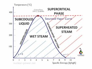
Steam can occur as in various forms depending on temperature and pressure. This article discusses on the topic saturated vs superheated steam.

Saturated steam is the steam in which water exists in both liquid and gaseous state whereas Superheated steam is the steam whose temperature is above vaporization point.

What is saturated steam?

As discussed above, saturated steam is the condition where gaseous and liquid water co-exist. The temperature at which this happens is called as saturation temperature and pressure at which this happens is called saturation pressure.

When we say that both phases of water co exist, it means that the liquid water is in a transition state. The liquid water starts getting converted to gaseous state. If we decrease the temperature, the gas particles will condense to become liquid, if we heat it further then the saturated steam become superheated steam.

Effect on saturation temperature with changing pressure

When we change pressure of the system, the saturation temperature also changes. At lower pressure, the saturation temperature is also less. For example, if we go to higher altitudes where the pressure is low, water will start boiling sooner.

The enthalpy of steam first increases with increasing pressure, after some point it starts decreasing with pressure. This change can be represented on Mollier diagram (discussed in further sections).

What is superheated steam?

As discussed above, superheated steam occurs when temperature of the steam is raised above the vaporization point. In this state of steam, all the liquid particles turn to gas.

The enthalpy of superheated steam is much higher than saturated steam for a given pressure and temperature. It can be shown on Mollier diagram. Mollier diagram is discussed in detail in later section of this article.

Enthalpy-Entropy diagram/ Mollier diagram

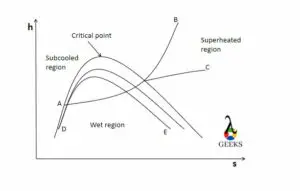
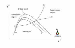
The characteristics of steam can be plotted on h-s diagram also called as Mollier diagram named after the Richard Mollier who plotted the diagram in 1904.

The diagram consists a set of curves that represents different characteristics of steam. The details about curves are given below-

  • Horizontal axis represents entropy (s).
  • Vertical axis represents enthalpy (h).
  • Line A-B represents constant pressure line.
  • Line A-C represents constant temperature line.
  • The dome represents saturated vapour line.
  • Internal lines (D-E) making a similar dome are constant dry fraction lines.
  • The tip of saturated vapour curve represents critical point.
  • Region on the left side of saturated vapour curve is sub cooled region.
  • Region inside the saturated vapour curve is saturated region.
  • Region on the right side of saturated vapour curve represents superheated region.

Note that constant pressure line and constant temperature line are parallel inside the saturated vapour dome.

Saturated Vs superheated steam
Image: Mollier diagram

Saturated and superheat steam conditions

Using the Mollier diagram we can find out the conditions required for saturated and superheat regions.

First we find the condition for saturated steam. For saturated steam condition, the dryness fraction of the steam should be between 0 and 1. For superheated steam, the dryness fraction of the steam should be greater than 1.

In a nutshell,

For saturated steam at given saturation temperature and pressure- 0<x<1

For superheated steam at a given temperature and pressure- x>1

Where x denotes the dryness fraction.

What is dryness fraction?

Saturated steam is a mixture of both water and steam. To find the amount of steam present in the mixture, the term dryness fraction is used.

This term helps in giving an accurate data of steam characteristics. Without this term, characteristics of water would also come into play. Dryness fraction is the amount of dry steam present in the water-steam mixture.

Mathematically,

x = mdrystream/mmixture

This term helps in finding the actual enthalpy of steam and determines the quality of steam. Quality in terms of quantity of steam in the mixture. 100% quality implies the dryness fraction is 1 and the mixture contains only dry steam.

Why is the heat transfer co efficient of saturated steam higher than a superheated steam?

Saturated steam is better at heat transfer than superheated steam.

Superheated steam is a bad conductor of heat and has low thermal conductivity which means it will have low heat transfer co efficient. Saturated steam has better thermal conductivity due to liquid and gas particles mixture. Liquid water being a good conductor of heat, increases the overall heat transfer co efficient of saturated steam.

Due to above reasons, saturated steam has higher heat transfer co efficient than superheated steam.

Turbine Efficiency:Complete Insights and FAQs

turbine efficiency 0

The efficiency of any device is a measure of its performance

The turbine efficiency is expressed as the ratio of useful work energy output to the input energy.

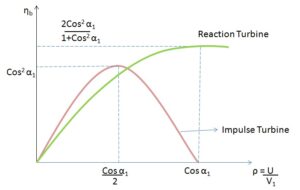
There are mainly two types of a steam turbines. One is an impulse turbine, and another is a reaction turbine. The efficiency of both turbines is different, and it depends upon its action of work.

There are many factors on which the turbine efficiency depends. It can be blade angle, guide vanes angle at the inlet to the turbine, velocity of steam, etc.

turbine efficiency formula

We can know and compare the performance of turbine with turbine efficiency

em%3E%7B3%7D h %7B4%7D%7D%7Bh %7B3%7D h %7B4s%7D%7D%7D%7D

Here,

h3 – enthalpy on point 3

h4 – the enthalpy point 4 (actual turbine)

h4s – the enthalpy point 4s (isentropic turbine)

The isentropic efficiency of the turbine can give us an ideal performance of the turbine. The heat rejected to the surrounding is to be assumed as zero. The isentropic efficiency can be calculated by the ratio of actual work to ideal work.

The ideal turbine is a device that works with 100 % efficiency. It means that all the input energy is converted into useful work. This type of turbine is impossible in the real world. There are always some losses present in the turbine in the form of heat and friction.

turbine efficiency
T – S Diagram of Rankine Cycle credit Wikipedia

turbine efficiency curve

the turbine efficiency curve for impulse and reaction turbine is shown below

turbine efficiency
Turbine efficiency curve for impulse and reaction turbine credit Wikipedia

What is stage efficiency of a turbine

The stage efficiency or gross efficiency of the turbine is related to the stages of blades.

The stage efficiency is the ratio work supplied on the blade by per kg of steam to the energy given per stage (per kg of steam)

Stage efficiency can also be expressed as the multiplication of nozzle efficiency and blade efficiency.

In an impulse turbine, there are stages of blades and nozzle set. The stage efficiency is the providing performance of stage by work done in the stages and enthalpy dropping in nozzles.

gif

how to improve turbine efficiency

The turbine efficiency can be improved by some factors discussed below

It can be enhanced by the superior blade design, Coatings of exhaust blade and geometry

Why turbine has more efficiency than pump

The pump and turbine efficiency can be compared based on fluid handling

The pressure losses in the pumps are higher than in the turbine. This loss can be reduced by making the boundary layer thin in the turbine.

The working fluid in the turbine is expanding from the inlet. At the inlet, the static pressure and the velocity rise continuously. The rising in the kinetic energy of the fluid leads to a decrease in losses. The thin boundary layer can decrease the losses of power.

In the pump, the boundary layer thickness of fluid is more due to deceleration to raise static pressure. This increase in thickness leads to an increase in the losses in the pump.

average turbine efficiency

The average efficiency of the turbine varies between some range depending on size and stage.

The average efficiency of a single-stage turbine is 40 % whereas, the efficiency for the multi-stage turbine is 65 – 90%.

The efficiency in the multistage turbine is high due to the moderate to high pressure ratio. The steam will get expanding through various stages, which is beneficial to efficiency.

What is the ideal efficiency range for practical turbines

The ideal efficiency range of a practical turbine is dependent on various losses.

The overall plant thermal efficiency for the steam turbine is 42- 45%.

The power plant running on the superheated boiler is working with fossil fuels like coal. There are many heat losses present in a practical turbine. Due to thermal losses, the efficiency of the practical turbine is low.

turbine vs piston efficiency

The turbine and piston engine can be compared for aircraft

The piston engine is more efficient compared to the turbine due to less specific fuel consumption.

The turbine is light in weight compared to piston engines. The weight of piston engines is more due to bore, turbocharger, etc. To reduce the unbalancing in an airplane, a long nose is provided.

What is the maximum efficiency of a generator

The generator is a device that provides electrical energy at the expense of mechanical energy.

If the losses are proportional to the square of load current, then the generator’s efficiency is maximum.

The generator efficiency can be stated as the ratio of output electrical power to input mechanical power.

The efficiency of the dc generator can be maximum if the variable and constant losses are the same. The variable losses are armature losses, and the constant losses are field circuit losses and rotational losses.

Saturated Liquid Line: Need to Know Critical Facts

download 2

If we consider the phase diagram of a pure substance, the Saturated Liquid Line and Saturated Vapor Line divide the whole phase diagram into three regions.

A pure substance undergoes state changes as per the variation in temperature, pressure, and volume of the substance. The solid line which separates compressed or sub-cooled liquid from the saturated mixture is known as Saturated Liquid Line.

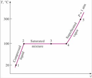
A simple saturated liquid line for water at constant pressure is shown in the Temperature-Volume diagram as below:

Image Credit: T-v diagram for the heating process of water at constant pressure https://www.unipamplona.edu.co/unipamplona/portalIG/home_34/recursos/01general/17012012/unidad_iii_termo_i.pdf

The saturated liquid line denotes the phase change of a substance from liquid to vapor. Below the saturated liquid line, the substance is in pure liquid form, and above it is in partial vapor form till enough heat is added to convert it to 100% vapor.

A substance occupies a higher specific volume above its saturated liquid line due to vaporization.

saturated liquid line

What is a Saturation Line

The saturation line is a point in the Temperature Pressure equilibrium diagram beyond which a substance or component in a system is either changing from liquid to vapor or vapor to liquid.

In general parlance, the Saturation line is synonymous with the concepts of Boiling and Condensation. In fact, both boiling and condensation begin with the saturation line as the starting point.

Linguistically speaking, Saturation refers to a state beyond which a particular system cannot accept more of a component: – Like a saturated solution of sugar in water or a sponge saturated with a liquid. If we add more sugar to a saturated solution of sugar in water, no more sugar would be dissolved if we kept the temperature and pressure of water the same. Under such a state, the sugar solution is said to be saturated.

Similarly, water in atmospheric conditions would start to boil at 100 °C. If the pressure of the system is maintained constant, more water will keep boiling off if more heat is added until all water has transformed into vapor, without any change in the temperature of the system. The temperature at which this phenomenon happens is called the boiling point.

On the other hand, if heat is removed from the water-vapor mixture, keeping the pressure constant, the vapor would start condensing at 100 °C, and it is called condensation point.  

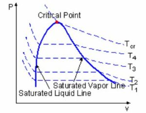
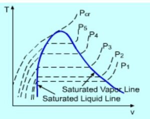
These boiling or condensing points vary with pressure for a particular component and can be denoted by what is called a saturated line in a PV or TV diagram, as shown below.

pic 2

Image Credit: PV diagram for a saturated line https://ecourses.ou.edu/cgi-bin/ebook.cgi?topic=th&chap_sec=02.2&page=theory

pic 3

Image source: TV diagram for a saturated line https://ecourses.ou.edu/cgi-bin/ebook.cgi?topic=th&chap_sec=02.2&page=theory

Definition of Saturated Liquid Line

A substance would exist in liquid form below its saturation line and as a mixture of vapor-liquid above it.

A saturated liquid line identifies the different temperature points in a PV diagram and different pressure points in a TV diagram of any substance beyond which it will cease to exist in pure liquid form.

At any point denoted by the saturated liquid line in the TV and or diagram above, if delta heat is added to the liquid at constant pressure, there will be no change in temperature but its gradual expansion and formation of vapor.

Saturated Liquid Line Temperature

Saturated liquid line temperature varies with system Pressure.

The saturation temperature of a substance shall increase with the increase in pressure, and hence the same is shown by a point higher up in the saturated liquid line of the PV/TV phase diagram.

Saturation liquid line temperature is the point where boiling starts when external heat is added, and the temperature remains the same until all the liquid has vaporized to vapor. This is also the temperature where condensation starts and continues till all the vapors are transformed into liquid. If heat is further removed from the system beyond the point of total vapor condensation, the liquid becomes sub-cooled. Thus the temperature of a sub-cooled liquid lies below the saturated liquid line temperature.

Frequently Asked Questions

Q. What is the definition of a Critical point?

Ans: Critical point signifies the point of a pressure-temperature curve at which liquid and its vapor can coexist.

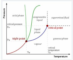
The top limit of the liquid-vapor equilibrium curve is known as a critical point beyond this point liquid and gas are indistinguishable and form a super critical fluid. The pressure and temperature at this point are known as critical pressure and critical temperature, respectively.

If we consider the PV diagram of water, the point where saturated liquid line and saturated vapor line intersect each other is known as Critical point.

download

Image credit: Liquid vapor Critical point in a pressure temperature phase diagram https://en.wikipedia.org/wiki/Critical_point_(thermodynamics)

Q. What is a Triple point?

Ans: A point where a small change in pressure and temperature may lead to phase change of a substance.

The point in the pressure-temperature phase diagram, where solid, liquid and vapor phases of a pure substance co exist in equilibrium is known as Triple point.

How To Reset Camshaft Position Sensor: 7 Important Facts

The camshaft position sensor can be reset with the precautions of other car equipment.

The performance of the inductive sensor can be checked with a voltmeter and ohmmeter. Induction phase detector resistance in between 200 to 900 Ω

The measured resistance will be verified by comparing it with standard car data.

Switch off the ignition switch before measurement.

Take out the induction phase sensor (camshaft position sensor)

Connect two terminals of the voltmeter with the sensor.

Start the engine and let it run on idle

Your RMS value should be more than 0.75 V

What is a camshaft position sensor?

The camshaft position sensor provides valuable data to the engine control system.

It sends positional data of camshaft and crankshaft to the ECU. This position data helps estimate ignition points and injection points.

camshaft position sensor
Crank shaft /Camshaft position sensor Credit Wikipedia

The camshaft position sensor data is used in the engine control system to carry out further steps of combustion. For any engine, the ignition point is essential for better performance. This data can be calculated by the positioning of the camshaft.

Camshaft sensor principle: Functional principle

There are two sensors used to define the position of the crankshaft drive in the engine.

This sensor works on the hall principle. The sensor records the ring gear and changes the voltage reading accordingly.

The change in voltage is recorded and sent to the transmitter device. The voltage signal is studied in a transmitter device, and the required data is produced from it. Combining the signal from the camshaft sensor and crankshaft signal is helpful to get to know the position of the first cylinder in the top dead center.

Where is the location of the Camshaft Position Sensor?

This sensor is helpful for an engine control system to generate required data.

It is utilized to get position and monitor the rotation of the camshaft. The location of the sensor is nearby the cylinder head. This location is convenient to read timing rotor coupled with camshaft.

The electronic control unit (ECU) decodes the signal as the angle of the camshaft. It will calculate the recognition of the cylinder based on the signal given by this sensor.

In modern engine technology of auto start and stop, This sensor scans the cylinder on expansion stroke. It is helpful to supply fuel and advance spark with your acceleration act. A faulty camshaft sensor warns you about its condition before it is useless.

Is it safe to drive with a bad camshaft sensor?

This sensor is helpful to improve the engine performance with signals.

You will not face any driving problems. The engine performance and fuel economy can be affected by lousy camshaft sensors.

This sensor is necessary to improve the performance and fuel economy of any engine. An engine electronic control unit controls the fuel supply and other systems. This ECU collects signals from various sensors, which is ultimately used for further calculation of another system.

The lousy camshaft sensor affects the engine ignition system. It will not be helpful to calculate information for spark advance and fuel supply at the right time. It will always be recommended that you keep your camshaft sensor up to date for the proper functioning of your vehicle.

Can I replace my own camshaft position sensor?

The camshaft position sensor is rarely found at fault except for some physical damages.

Yes, You can replace the camshaft positioning sensor with a basic repair manual (DIY) for your vehicle. You should know its look and location in the car.

The camshaft sensor is working more for an extended period without losing its performance. If you want to replace it, you should know how it looks like and where its location is. Though the faulty replacement of the camshaft position sensor is not lead to stopping your vehicle from working. If you have made any mistake in replacement, you have to visit a mechanic for further guidance.

What causes a camshaft sensor to go bad?

Several aspects can affect the performance of camshaft position sensor

  • Damage due to water
  • Wear or tear
  • Damage due to corrosion of metallic parts
  • Damage due to engine oil leakage
  • Overheating or melting
  • Damage due to short circuit
  • Damage due to fire or spark
  • Other physical damages

There are many different possible reasons to affect the performance of the camshaft positioning sensor. The camshaft positioning sensor can work properly if you maintain your car regularly.

Which is a common problem for camshaft position sensor circuits?

The camshaft position sensor delivers a positional signal to the Electronic control unit circuit.

The sensor circuits can fail mostly with accidents or oil leakage from the engine. It will stop or reduce the signal sending capacity of the sensor.

The engine oil can cause leakage and affect the sensor if improper tightening or loss of engine components. The leakage oil stops the signal carrying capacity of wiring and circuits.

Can you clean a camshaft position sensor?

Periodic maintenance is required for any equipment associated with the car.

It is easily clean camshaft position sensor  with some care. Read more information below for proper steps for cleaning.

The first step is disconnecting the battery with an engine so that all electrical and electronics circuits remain off. Find the place of the camshaft position sensor in your vehicle.  

Disconnect the sensor’s three cables and remember it at the time of connection. Now clean the sensor with a cleaning solution and dry it before connecting.

Connect the sensor with its original three wire location. Connect the battery again and let the system run. You have cleaned the camshaft position sensor. Repeat this procedure after some period of time.

Firing Order And Firing Interval: 7 Facts You Should Know

Vengine numbering 1

Firing order and firing interval have different meanings.

Firing order is the sequence in which the cylinders inside a multi cylinder engine are fired whereas firing interval is the time duration after which the same spark plug (cylinder) gets fired. Firing interval can be used in a single cylinder engine as well whereas firing order exists only when there are multiple cylinders used.

What is firing order?

Firing order helps reducing the chances of vibrations and regulates proper heat transfer.

As discussed in above section, firing order is the sequence with which cylinders inside the engine are fired. This term comes into play when there are multiple cylinders inside an engine.

Firing order of multi cylinder engines

Firing order means the chronology with which the cylinders are fired.

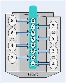
Below are some of the common firing orders used for different types of multi cylinder engine-

Number of cylindersFiring orderEngines using respective firing order
21-2Buick Model B
31-3-2Perodua Kancil engine
41-3-4-2,1-2-4-3Ford Taunus, Ford Kent
51-2-4-5-3,
1-3-5-4-2
Volvo 850, GM Atlas Engine
61-5-3-6-2-4,
1-4-3-6-2-5
Nissan L engine, Volkswagen V6s
71-3-5-7-2-4-6Radial engine
81-8-7-3-6-5-4-2,
1-8-7-2-6-5-4-3
Nissan VK engine, GM LS engine
91-10-9-4-3-6-5-8-7,
1-6-5-10-2-7-3-8-4-9
Dodge Viper V10, BMW S85, Ford V10
Table: Firing orders of multi cylinder engines with examples
Firing order and firing interval
Image: Numbering of cylinders in multi cylinder engine

Image credits: Wikipedia

What is firing interval?

Firing interval is the time between two successive firings of same cylinder/spark plug.

The spark plug has to fire during the ignition stroke. Firing of the spark plug is so precisely timed that it automatically fires when its the time for ignition stroke. If it takes x milliseconds to complete one full cycle then after every x milliseconds, firing takes place.

What is the significance of firing interval?

Anything which is more systematic and more even works more efficiently.

The significance of firing interval is as follows-

  • Minimizes vibrations.
  • Provides increased number of even pressure pulses.
  • Uneven firing interval causes throaty and growly sound in engines

What happens if firing order is not maintained?

The cylinders are fired in a particular sequence because of vibrations and heat transfer issues.

If the firing order is not maintained, lets say, if adjacent cylinders keep firing for a long time. Then the heat generated inside the engine will be very high and high sink temperature is always less efficient. The vibrations from the adjacent cylinders will have serious impact on bearings supporting the crankshaft.

Hence, a proper firing order is desirable.

How is firing order controlled/set?

The firing order is controlled by the ignition system of the engine. It provides necessary current to specific cylinders at specific times when ignition is required.

The distributor controls the spark in each spark plug of a multi cylinder engine in correct order. Changing the distributor position will directly affect the firing order of the engine. But this work needs to be done by expert mechanic. Changing of firing order is not recommended.

How is firing interval controlled/set?

The ignition system of the engine also controls the firing interval. It gives the spark at exact moment when required.

Firing interval is controlled by the action of cam which acts as circuit breaker. When the circuit breaker is open, capacitor starts charging creating a high voltage surge in the circuit. This high voltage surge creates the spark. The cam rotation is perfectly timed in a manner such that it breaks the circuit at the precise moment.  

Different parts used in controlling firing order and firing interval

The ignition system of the vehicle controls the firing order and firing interval of the engine. Most commonly used ignition system is magneto and battery ignition system.

In a magneto ignition system, following parts are used-

  • Magneto– A rotating magnet that controls the voltage.
  • Distributor– It distributes the current to the spark plugs in a correct sequence.
  • Capacitor– Capacitor are nothing two parallel metal plates whose each end is connected to circuit. It is used for storing charge
  • Spark plugs– Spark plugs are responsible for igniting the air fuel mixture.

Magneto itself generates power for the ignition system. Hence, it does not need any external source of power. In battery ignition system, batteries are used as external power source.

Coolant vs Refrigerant: 7 Important Factors Related To It

Refrigerant 199x300 1

Coolant and refrigerant are not entirely different. This article discusses about the topic Coolant vs Refrigerant in detail.

Coolant is a broad term and refers to a fluid that absorbs heat from the system. This way the temperature of the system can be regulated. When the temperature needs to be reduced below ambient temperature, then the coolant is referred as a refrigerant. Hence, all refrigerants are coolants in broader sense.

Definition of coolant

As discussed above, coolant can be any fluid that is used to remove heat from the system and reduce the temperature of the system.

The coolant can work without changing its phase (whether liquid or gas) or by changing its phase (liquid to gas and gas to liquid).

Uses of Coolant

A coolant is used in places where the temperature needs to be regulated. Excess heat can create a lot of problems in engines, machine components etc.

Different places where coolant is used are-

  • Inert gases are used as coolants in nuclear reactors.
  • Vehicle engines use cooling fluid/ water jackets around engine to absorb the excess heat generated in the cylinder.
  • Rocket engine nozzles have small tubes through which liquid oxygen is passed that cools the nozzle to a desired temperature, without which the metals used in nozzle wouldn’t have survived the high temperature generated because of exhaust gases.

Types of coolant

Coolant comes in various forms and phases. It is important to know the nature of coolant because an improper coolant will not be able to regulate the temperature of the system to required value.

The different types of coolants used in industry are-

  • Gaseous- Hydrogen, Boron, Sulfur Hexafluoride are commonly used gas coolants. Hydrogen is used in turbogenerators, Boron in nuclear reactors and Sulfur Hexafluoride in switches, transformers or other kind of circuit breakers etc.
  • Two phase- These types of coolants uses both the phases of coolant that is liquid and gas. These coolants are usually used in applications where desired temperature is below ambient temperature. These coolants are called as refrigerants.
  • Liquids- Water is the most common liquid coolant. But it cannot be used while dealing with metals due to corrosive nature of metals. Various mineral oils are used as coolant in place of water to cool machine components. For example, special oil is used to cool the job while machining on lathe.

Definition of refrigerant

Refrigerants are the coolants that are used in low temperature applications. Refrigerants use their latent heat of vaporization to reduce the temperature to significantly low value.

Refrigerants bring with them a lot of environmental concerns which is why there are many rules and regulations of refrigerants.

Refrigerant
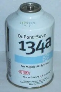
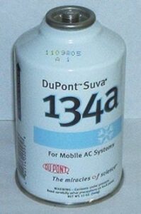
Image: Refrigerant

Image credit: Stephanie~commonswiki, Can of DuPont R-134a refrigerantCC BY-SA 3.0

How do refrigerants cool the system?

Refrigerants absorb heat and change their phase to achieve the desirable temperature. Some gas cycles may use only one phase of the refrigerant for example Bell Coleman cycle or Reverse Brayton cycle.

In a typical refrigeration cycle, the refrigerant enters the system in liquid form. It absorbs the heat from the system and gets converted into gaseous form. Later on, the gaseous refrigerant is converted back to liquid state so that it can be used again.

Coolant Vs Refrigerant
Image: The observed stabilization of HCFC concentrations (left graphs) and the growth of HFCs (right graphs) in earth’s atmosphere.

Image credits: Wikipedia

What are desirable properties of refrigerants?

The use of refrigerants is regulated due to their toxic and inflammable nature. They also give out green house gases which are harmful for ozone layer.

Due to above reasons, some refrigerants are banned. An ideal refrigerant has following properties-

  • Non toxic
  • Non corrosive
  • Non flammable
  • No green house gas emission and ozone layer depletion potential.
  • Freezing point below the target temperature.

Is AC coolant and engine coolant same?

Both AC coolant and engine coolant are used for cooling. But their applications and mechanism differ from each other.

Water is typically used as engine coolant. It cools down the engine by absorbing heat and transferring it to the outside air and also transfers heat to the cabin of the vehicle when vehicle heating feature is turned ON. It is mixed with anti freeze substances so that the water does not get frozen. AC coolant is used for absorbing heat from the cabin and emitting out to the atmosphere. The AC coolant will change its phase from liquid to gas and back to liquid.

Hence, the major difference between the two is the application (one is used to cool engines and other is used to cool the cabin) and other difference is the mechanism of cooling (engine coolant does not change its phase whereas AC coolant switches its state from liquid to gas time to time).