Why Do We Use AC Instead Of DC:Interesting Aspects on Different Industires and Home

This article has discussed the various points why do we use AC instead of DC in multiple applications or appliances used in homes and industries.

Let’s discuss different application why do we use AC instead of DC as:

  • Alternative current (AC) can be a step-down or step-up very easily by using various methods such as transformer to required value while losing minimum energy during conversion, as transformer works efficiently with AC power supply.
  • Alternating current (AC) is used in industry for transmission in the generation of electricity as generation of alternating current is much cheaper and easier than that of a DC voltage. For Higher voltages and AC has much better efficiency in DC during transmission. 
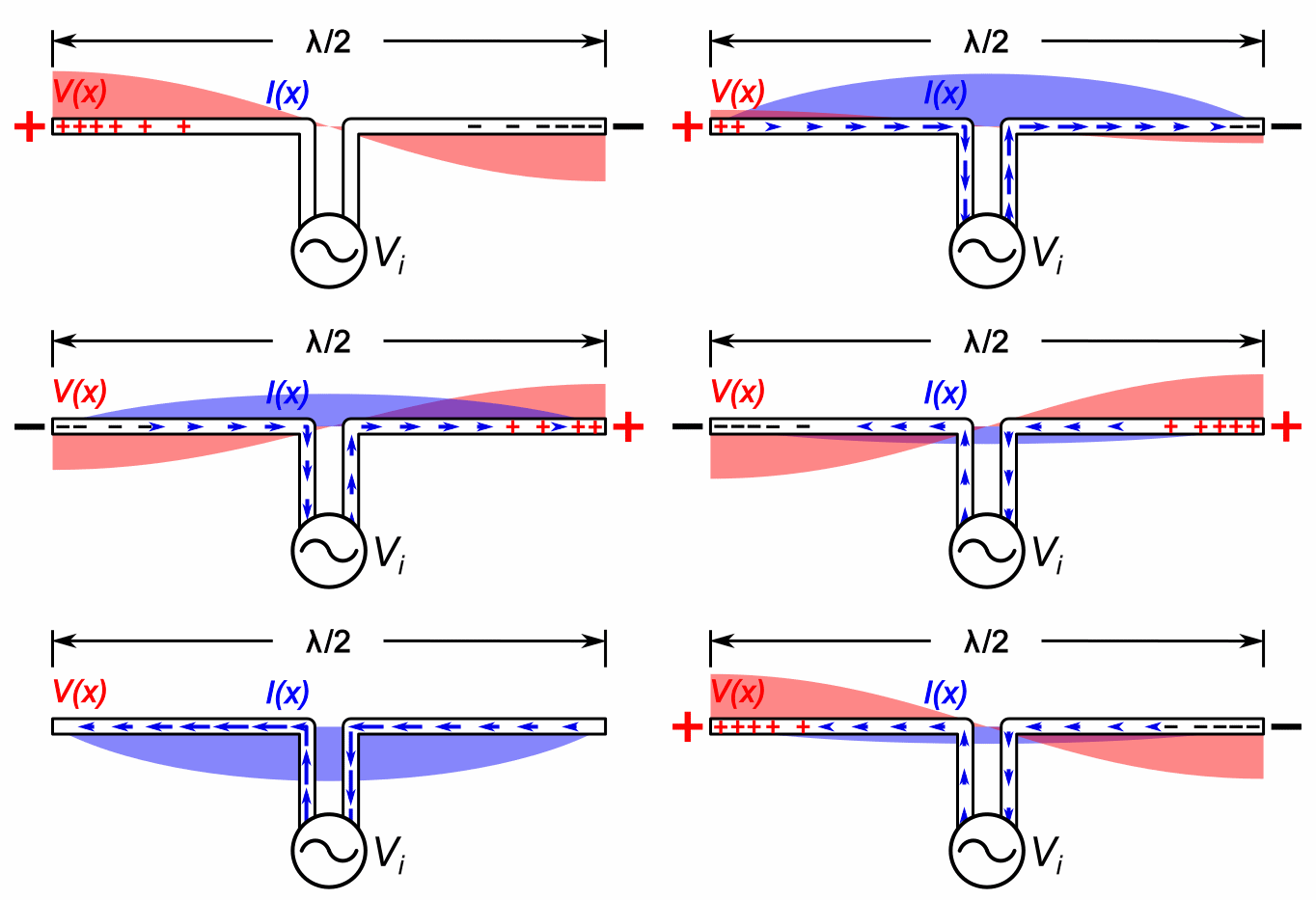
why do we use AC instead of DC
Image Credit: Diagram costs over line length (distance) in comparision HVAC 3-phase systems versus HVDC systems By wdwd – Own work, CC BY 3.0,
  • The devices that convert electrical energy into any mechanical energy use Alternative Current as a power supply, as when energy conversion is easier with AC as loss during conversion is lower the DC power conversion.
  • Generally, for all types of operations in transformer, transformer use of AC supply is the main power supply. Where DC supply does not work properly with transformer as DC cannot easily generate an alternating magnetic field. The fundamental requirement for the operation of the transformer needs a change in the magnetic field, which induces the voltage in the second coil.
  • High-voltage AC is relatively more efficient than DC for sending electricity over a significant distance. High Voltage generation in AC is relatively more accessible than that in DC.
  • A Single-phase AC power supply is used in the home. In contrast, a three-phase AC power supply is used for commercial and steel facilities to accommodate high-voltage load better, for easy generation, transmission, and less maintenance requirement.
  • An AC induction motor is easy to use, whereas a DC induction motor for proper working requires an additional commutator brush and switches.
  • Arc generated in an AC circuit can be easily extinguished or can be self-extinguished, given that an AC has two zero-crossing points in its every complete cycle. In contrast, Arc generated in DC is much stronger and cannot be self-extinguished as DC does not have any zero-crossing.
1024px Types of current.svg
Image Credit: Alternating current or AC (green curve). Direct Current or DC (red line), The horizontal axis measures time (it also represents zero voltage/current) ; the vertical, current or voltage. By Zureks – Own work, Public Domain,
  • The AC generator is more efficient than the DC generator. Due to various losses in DC generators such as eddy current loss, mechanical loss, sparking, copper loss, and hysteresis loss, DC generator efficiency reduces. An AC generator does not require a commutator; maintaining an AC generator is much easier than that of a DC generator. The AC generator is very easily able to generate high voltage relative to the DC generator.
  • Adding switches in the AC circuit is relatively more accessible than that of the DC circuit. When the AC circuit is switched off, a voltage Spark is generated inside the switch, which gets self-extinguished as AC has two zero-crossing points in its complete circle. Wherever in DC, both current and voltage are constant when switched off in DC circuit, the voltage is generated inside the switch stays for longer than that of AC if an Arc stays for longer in the circuit switch contacts making it burnt, pitted, overeating or premature switch failure.
  • Three-Phase AC supply is used because with a three-phase supply, the electrical power is more consistent, which allows the machine to run more efficiently, and the device becomes more durable
  • Three-phase AC energy system is used in various industries which use has high power demand three-phase AC system is used because power delivering through three-phase AC system is constant, can be used for more efficient use of materials, the installation cost is lower, the size of equipment reduces with the use of three-phase power supply etc
  • In the household, the three-phase connection is not required as the power consumption is not as high as industries, but if there are a lot of heavy appliances used in a house, then a three-phase connection may be installed as a requirement
  • Single-phase AC connection is generally used in residential appliances as single-phase AC is more efficient up to 1000 watts, design costs less, and the design is simple, the large array of application use of single-phase AC supply.
  • Three-Phase power supply is used in mobile towers, data centres, aircraft, power grids, ship boards, etc. it is as well as many electronic loads that need more than 1000 watts of power for operation
  • The three-phase power supply is used in power-hungry and high-density data centres. In high-density data centres, a more powerful computing system is being used and is packed in a small area. Some racks hold several servers that can draw 20 to 30 KW of power, so constant power and efficiency matter; that’s why a three-phase AC supply is used. By using a three-phase AC supply in the high-density data centre, losses can be minimised as well as load balancing across power is more straightforward, which results in optimum utilisation of power supply.
  • AC drivers are widely in use in process industries to increase the efficiency of each piece of equipment. AC drivers control the speed of the electric motor as a requirement which reduces the overall energy consumption by 30 to 40%. In contrast, AC drivers in the industry used to regulate and control types of equipment such as conveyors, fans, machine spindles, etc.
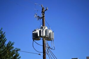
electricity 2864988 640
Image by F. Muhammad from Pixabay
  • The cable size of the AC power supply is somewhat lighter relative to the DC power supply cable for the same rating.
  • Electrosurgery uses the characteristics of a high-frequency alternating current for the removal or destruction of tissue. In this procedure, the high oscillating current is used to heat the tissue; the degree of destruction depends on the frequency of oscillation and the power of the supply current.
  • Because of the two advantages of AC over DC on generation and transmission, alternate marine power (AMP) uses AC for operation.
  • A general air conditioner uses AC over DC; some Air Conditioner uses DC for operations, but that DC AIr conditioner has low power applications. Air Conditioners require AC because of their high power consumption applications.
  • The motor, which uses AC as a power supply, requires lower startup power and has better control over starting current and acceleration can be customised into various speed and torque requirements and ac Motors are more durable than DC Motors.
  • In alternating, current can be easily converted to direct current by using a rectifier, filter, diode, etc. The conversion from DC to AC can be done by a complicated circuit of an inverter that costs much more than that of AC to DC Converter.
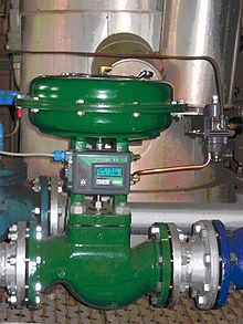
Control Valve Uses: Critical Insights and Facts

This article discusses about control valve uses. Control valve as the name suggests, controls the flow rate and related properties of flowing fluid such as pressure and temperature.

What is a control valve?

As discussed above, a control valve is a device that controls the flow rate and related properties such as pressure and temperature.

The control action takes place as directed by the signal from controller. It opens and closes which helps in controlling the fluid flow in the passage.

control valve uses
Image: Globe control valve
Image credits: Pl_control_valve.GIF: Rafał Rygielski derivative work: User A1 (talk), Pl control valveCC BY-SA 3.0

What are different types of pressure control valves?

Pressure control valves are most commonly found in every hydraulic and pneumatic system.

The different types of pressure control valves used in industries are as follows-

  • Pressure relief valves– Usually the hydraulic system and pneumatic systems work in a specified pressure range. When the pressure goes beyond this range, that is when relief valves come into picture. They avoid the components from getting damaged by controlling the pressure differential.
  • Sequencing valves- If the circuit has more than one actuators then it is necessary for these actuators to move in a sequence. This can be achieved by using limit switches, timers or digital control devices with sequencing valves.
  • Pressure reducing valves– The name itself implies that these valves are used for reducing the pressure of the fluid that is flowing. This ca be achieved in a single stage as well as two stages depending upon the application. This provides a better repititive accuracy. In hydraulic applications, there may be blockage of flow due to oil contamination.
  • Counter balance valves– Counter balance valves are not used directly, they are used passively. That means they are closed valves which maintain a set pressure in certain portion of a flowing circuit. This is done usually to achieve counter balancing of weight. The design of this valve is perfect for counter balancing an external force or counter act a weight as in a press to keep it from free falling.

What is a directional control valve?

Directional control valves or DCVs are the most important parts in both hydraulic and pneumatic systems.

Directional control valves allow the fluid to flow in different passages from one or multiple sources. These valves are actuated by the action of a spool whose position restricts or permits the flow of fluid.

What is a spool in directional control valve?

Spool is responsible for controlling the fluid flow.

It is used to regulate/control the flowing fluid and connects internal passages and port. Its design includes lands and undercuts which are encased in precisely machined housing. The lands and undercuts will open and close flow paths once the spool shifts.

Classification of directional control valves

The classification of directional control valves or DCVs is done as follows-

  • According to number of ports– Depending on the number of ports, directional control valves are classified as 2-way, 3-way or 4-ways valves.
  • According to type of spool– Depending on the type of spool used, they are classified as poppet, rotary and sliding valves.
  • According to actuating method used– The position of the valve is changed by the actuating the handle which can be done manually, mechanically or electronically.

Directional Control Valve benefits and features

The features of directional control valves make them beneficial for industries to use them.

The features and benefits of directional control valve are as follows-

  • Custom porting is available.
  • It is light in weight as aluminium is used for construction.
  • Blocked, open and power beyond options are available.
  • High flow options are also available.

Directional control valve uses

Hydraulic directional valves are used in many agricultural and Mobile industries to have smooth operation and low pressure drop.

The directional control valves are used in many applications such as-

  • Car carriers
  • Machinery
  • Assembly line
  • Energy production
  • Construction machines
  • Material handling cranes
  • Trucks and rigs

What are the things to be considered while choosing a directional control valve?

The following points should be considered while analyzing the performance of a directional control valve-

  • Dynamic power limit.
  • Static power limit.
  • Resistance to flow
  • Switching time
  • Leakage

What is a differential pressure control valve?

Differential pressure valves or DPCVs are valves that are used in heating or cooling systems to regulate sub-circuit pressure to desired or given maximum.

A differential pressure control valve reduces energy consumption, provides silent operation and has simple commissioning process.

How does a differential pressure control valve work?

A differential pressure control valve includes a capillary tube, spring and a diaphragm.

A DPCV controls or regulates differential pressure in the circuit depending on the impulse of pressure coming from the inlet and direct pressure from the outlet side. The spring force will be equal in magnitude as the differential pressure force across the circuit.

Differential pressure control valve uses

Differential pressure control valve sets the differential pressure in the circuit to a maximum due to which we get following uses of differential pressure control valve-

  • Extremely efficient
  • Reduces noise and provides a silent operation.
  • Reduces energy consumption.
  • Makes the commissioning process less complex.
  • As they are pressure relieved so low force actuators can be used.
  • Keeps high controllablity in the system.
  • Reduces pump head.

What is PICV?

PICV stands for Pressure independent control valve.

These valves are used in heating applications where differential pressure exists, by adding an actuator these valves act as flow limited control valves that balances the system and hence provides the best possible indoor comfort and energy efficiency.

What are the features and benefits of pressure independent control valves ?

PICV provides similar features and benefits as that of DPCV.

The features and benefits of pressure independent control valves are-

  • Stable room temperature– It eliminates the overflow situations at partial load conditions that helps in maintaining stable room temperature.
  • Improved indoor comfort– As the room temperature becomes more and more stable, the indoor comfort increases. The desired temperature is accurately met which also increases the productivity of employees.
  • Energy savings– A perfectly balanced system increases the energy savings and cost savings.
  • Reduced maintenance costs– As these valves ensure perfect working conditions, the actuators require few movements which in turn reduces the need of maintenance.

Valve Positioner: What Is It, Working, Type, Necessity And FAQs

Positioner 3 300x300 1

Valve Positioner is one of the most extensively used control valve accessories in different industries.

To regulate the rate of gas and liquid flow, a large number of valves are used in oil and chemical plants as well as food, pharmaceutical, steel plants. Each valve is associated with a positioner that controls the valve’s position according to the command from the control system.

What is a Valve Positioner?

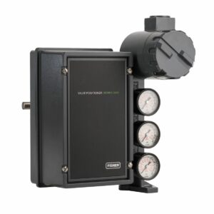
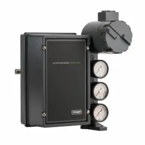
Valve Positioner is a device installed with a control valve to get precise and rapid control over flow, to reduce frictional effect and steady valve position even with fluctuating pressure.

valve positioner

Valve Positioner, Image Source: cascadeautomation

The use of a Valve Positioner with a control valve is essential to get accurate and quick control without any hysteresis. The controller sends a direct input signal to the Positioner instead of the actuator. The control signal applied to the Positioner operates the actuator stem through a flapper nozzle mechanism.

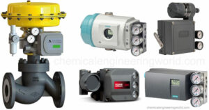
Control Valve Positioner 2

Valve Positioner, Image Source: chemicalengineeringworld

Valves are a vital part of any industry that is installed on pipes to control the flow rate of gases and liquids. Hundreds and thousands of valves are required as per the capacity of a plant. Proper control of opening and closing and adjustment of degree of opening of these valves is essential. To get the correct stem or shaft position as set by the control system, Valve Positioners are used widely so that depending on the input from the controller, it can adjust the air pressure to the actuator diaphragm to maintain the correct stem position of the valve.

Where is a Valve Positioner located?

Valve positioners are installed with a control valve to regulate the position of a valve depending on the predecided data for a process variable which may be flow, pressure, or temperature.

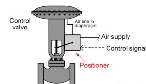
As per the type of Valve actuator, the position of Valve Positioner is determined. Normally, the location of a Positioner in case of pneumatic type actuator for a linear control valve is yolk or top casing. In a rotary control valve, the Positioner is located close to the end of the shaft.

Whether rotary or linear, in either types of control valve, the positioner sits and travels along with the valve stem. It measures the distance travel in case of linear valve and degree of rotation for rotary valves and controls the valve as per the points set by the controller.

Control Valve Positioners 1

Location Of a valve Positioner, Image Source: instrumentationtools

What is the necessity of a Valve Positioner?

Valve Positioner helps a control valve to respond quickly as per the changes of the process variable. They are advantageous for a system where fluctuations are the main obstacles to efficiency and quality.

The necessities of a Valve Positioner are explained below:

  • Speed: Valve Positioner minimizes the response time of the system, whether operating above or below the set point
  • Accuracy: A Positioner gives better resolution and more precision than an actuator can provide on its own. Controller send input signal directly to Valve Positioner. The feedback mechanism provided in the positioner allows to cross-check the valve position and readjust air requirement/pressure to reposition the stem as per the signal provided by the controller. Reduction in friction: Reduces friction effect of valve stem packing, especially beneficial for high-temperature packing material like graphite.
  • Range: Valve Positioners also help to control a wide throttling range.
  • Split Ranging: Using a Valve Positioner, we can use two valves with one controller(4-12 mA and 12-20mA) without any error.
  • Seating friction: Help to defeat seating friction in case of a rotary valve.
  • Increased flexibility: By using a Valve Positioner actuator is enable to face high apparatus air supply pressure.
  • Flexible configuration: Utilization of a Positioner removes the limitation on distance between the controller and the control valve as the control signal can be sent electronically and converted to pneumatic signal at the input point of the Positioner. On the other hand if an actuator is operated pneumatically over long distance, the control becomes erratic.

Valve Positioner types

A Valve Positioner can receive or transmit both electrical as well as pneumatic signal. The classification of Valve Positioner is based on type of signal it can receive and transmit or a combination of both. 

Different types of Valve Positioners are:

  • Pneumatic Valve Positioner:  This type of Positioner get pneumatic signal from controller and they also transmit pneumatic signal to the actuator. They provide a high air pressure to change the position of the actuator and are quite safe for use.
  • Electric valve positioners: They transmit and accept electrical signals.
  • Electro-pneumatic valve positioners: Also known as “Analog Positioner” because the electrical input received are in the form of analog signals. An electrical signal is fed from the controller but in return Positioner deliver a corresponding pneumatic signal to the pneumatic valve actuator.
  • Digital or “smart” valve positioners: Popularly known as “Smart Valve Positioners.” This type of Positioner uses a microprocessor to control the valve actuator and record and monitor data. The electrical input is in the form of a digital signal, and the corresponding output is a pneumatic signal.

Valve Positioner working principle

A pneumatic Valve Positioner is a mechanical device employed to fine-tune the movement of the stem of a control valve.

The pneumatic Positioner is provided with a feedback mechanism to accurately identify the control valve stem position and compares it with the input signal. Based on the feedback signal, the positioner varies the supply of air to the actuator stem in order to bring the stem into the position dictated by the signal sent to the Positioner from the controller. 

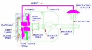
There are two philosophies on how a positioner is implemented. One is where the air is used to opena valve stem, and the other is when to air the used to close a valve stem. The description of the mechanism noted below is for the second case, i.e., the air is used for closing a valve stem. This is also called a direct-acting Valve Positioner.

Direct acting valve positioner

Direct Acting Valve Positioner, Image Credit: instrumentationtools

The Positioner is normally fitted into the yolk or pillars of the actuator. It is operated by an input air pressure of 3-15 psi (0.2 bar to 1.1 bar); as the signal is provided from the controller to open the valve stem, the input air pressure to the input instrument increases. The input pressure acts on the input signal diaphragm, which drives the diaphragm along with the flapper connecting stem. The flapper connecting stem opens the supply flapper allowing the supply air to act on the actuator stem diaphragm.

During this time, the exhaust flapper is in the closed position as the flapper connecting stem is deflected to the right. As the air pressure is increased, it forces the valve stem down. As shown in the figure above, the positioner lever moves clockwise as the valve stem goes down.

Reverse acting valve positioner
Reverse Acting Valve Positioner,
Image Credit: instrumentationtools

Due to this clockwise rotation of positioner lever, range spring experiences a compression through cam. As soon as the valve stem reaches the position as per the set point provided by the controller the range spring exerts a balancing force closing both the exhaust and supply flapper and the desired control action is achieved.

On the other hand, if the controller sends a signal to open the valve, the signal pressure decreases. With the decrease in signal pressure, the force from the range spring push the flapper linking stem towards left direction. As a result, the exhaust flapper is opened. The force acting on the actuator diaphragm also decreases causing a upward movement of the valve stem until an equilibrium in force balance is achieved.

Is DVI Better Than HDMI- Exhaustive Comparison and Detailed Facts and FAQs

This article enlightens upon the question Is DVI Better Than HDMI or not. Digital Visual Interface is shortly called DVI. DVI cables came into the market before the high-definition media interface or HDMI. 

Both HDMI and DVI have some pros and cons. They look different, function differently, and allow different outputs. But in the broader view, HDMI supports audio along with video, has a better data rate, is more available, and is compatible with more devices; all of these make HDMI a more suitable option. 

ParametersHDMIDVI
Time of foundationHDMI was designed in 2002.DVI was designed in 1999.
SizeHDMI is bigger than DVI.The DVI plug is much smaller in size.
StructureThe HDMI cable has a thin gap surrounded by 19 pins.DVI plug has 24 small pins, sometimes with three different rows and one big pin.
Data rateHDMI 2.1 supports 42.6 gbit/sDVI supports 9.9 gbit/s.
ResolutionSupported resolution is Upto 8kMaximum resolution is 3840*2400
Refresh rateMaximum supported refresh rate is up to 120 Hz.Maximum supported refresh rate is 60 Hz.
Audio compatibilityIt supports audio transmission.Audio transmission isn’t supported by DVI.
Is DVI Better Than HDMI- closer view of an DVI plug
DVI Plug; Image Credit : Pinterest

What is DVI and its types? Explain in detail.

Digital Visual Interface, commonly known as DVI, is a platform that transmits video signals. We cannot get audio through the DVI cable. DVI consists of three types- DVI-A, DVI-D, and DVI-i. 

DVI-A or DVI Analog is the oldest version. It can only transfer analog video signals. DVI-D is the most used out of all DVI types. Here, D stands for digital (transmits digital signals). We can classify it in single and dual-link. DVI-i and DVI-D are almost the same, but it allows analog and digital signals both.

DVI-D single link cable
DVI-D single link cable; Image Credit: Flipcart

Is DVI Better Than HDMIFAQS

Is DVI or HDMI better for gaming?

HDMI is the best option after DisplayPort when it comes to HD gaming. DVI doesn’t allow audio transmission, which HDMI does, and it is not a viable choice in high resolution and refresh rate. 

In 1080p or even 1440p and 4K gaming, both DVI and HDMI work fine (without the audio part). But if we think about refresh rates, HDMI is the preferred one. While dual-link DVI can still work at a 60 Hz refresh rate, we have to use HDMI for 144 Hz or more refresh rates. For 4k, DVI doesn’t work over 30 Hz.

Is DVI or HDMI better for PC?

Out of DVI and HDMI, it is better to opt for an HDMI cable. Most of the devices are HDMI compatible, and even HDMI is their default connector. Moreover, it can carry both audio and video over just a single cable. 

While experts recommend HDMI for PC, using already existing DVI won’t be an issue. We certainly get better quality A/V from the latest HDMI standards, but the difference is noticeable in large monitors. So, for basic display, DVI works fine. If we want audio, using HDMI will help us reduce the number of cables.

Does HDMI or DVI have a better picture?

In terms of picture quality, both DVI and HDMI are at par. The picture quality depends upon the monitor. If the monitor can’t show higher resolutions or color schemes, it doesn’t matter whether we use HDMI or DVI.

DVI supports 8-bit RGB colors, while through HDMI, we can display up to 12-bit different color spaces. Also, HDMI is capable of handling 8k resolutions at 120 Hz, where the maximum possible resolution for HDMI is 3840*2400 at 30 Hz. So HDMI appears better than DVI in some specific cases.

Is DVI better than DisplayPort?

Between various A/V devices, DisplayPort is the most preferred of all. Be it a resolution, cable need, or audio compatibility, DisplayPort is a better choice than DVI. So, for many reasons, DisplayPort is finer.

If we have proper systems, we can stream up to 8k video through the latest versions of DisplayPort. DVI dual-link can not even reach up to 4k resolution. Also, the biggest drawback for DVI is the lack of audio transmission. On the other hand, we can run multiple monitors through one cable in DisplayPort.

Do DVI to HDMI adapters work?

HDMI standards are mostly backward compatible. So we can utilize DVI to HDMI adapters in case we have a system with only DVI. But we need to make a separate audio channel as DVI does not support it.

The DVI-D port on the adapter has one big pin and 24 small pins on one side, and an HDMI port on the other side. We need to connect the DVI side of the adapter to the computer and then connect an HDMI cable on the opposite side. Now, we can join the HDMI cable to any compatible device and make things work.

Read more on….How Does A HDMI Arc Adapter Work: What, How and In depth Facts

Can you connect DVI to HDMI?

DVI to HDMI adapters come in handy if we want to connect DVI and HDMI. The cable allows us to join the DVI output with the TV’s HDMI input. Following are the steps to do this task-

1. Turn the display and the TV off.

2. Connect the DVI end of the adapter to the DVI output and the HDMI end to the HDMI port on the TV.

3. Connect a separate audio cable for sound and turn on the display.

4. Follow the instruction manual of the TV to set the HDMI, and the job is done.

EBHKZgdaQajhzfRPGyeDenlD4CrxCm8yhL0T0rW3AD4TnGyIu Mojuc3RxnWC5Dlb EuXuV J1ntts8AMBL4wEIrY2b1hmq79O1InHZucn2Nwe1IHdJuIJqUmUU yAVLX69pvAai
DVI to HDMI adapter; Image Credit: Amazon

Can I go from DVI to DisplayPort?

DVI to DisplayPort connection is possible. There are different DVI to DisplayPort adapters available in the market that help to connect a secondary monitor with a DVI port on the computer. 

The source device, with the help of DisplayPort specifications, can generate a DVI signal of DVI type. So we can use an adapter/ Displayport to DVI cable with a monitor having DVI input. But, the reverse is not supported, i.e., we can not use the DVI output of a video card to the DisplayPort input of a monitor.

DVI to DisplayPort Adapter
DVI to DisplayPort Adapter; Image credit: ubuy

What Are Valves Uses: Critical Insights and Facts

Valve

The device used for regulating the flow of fluids in passage ways are called as valves. This article tells us about what are valves uses and related insights.

Application of valve in industry

Industries use many types of valves which include gate valves, ball valves, globe valves, butterfly valves and check valves. 

The applications of above mentioned valves are given below-

  • Gate valves– They are used in high temperature and pressure conditions. They are used for binary operations such as ON/OFF. They can be used in both directions inside a flow circuit. They operate on low friction and can be used both ways.
  • Globe valves– They are generally used for throttling purposes. These valves are used as stop check valves as their opening and closing time is much shorter than other valves. The body ring seating surface is easier in globe valves.
  • Ball valves– These valves are used to regulate the flow of corrosive fluids and slurry and are also used in oil industry. They provide leak proof service.  They are compact and requires little or no lubrication.
  • Butterfly valves– These valves are used in pharmaceutical, chemical and food processing services. They are used for low pressure and low temperature applications. They can be installed without pipe dislocation. They are very reliable and require little or low maintenance.
  • Check valves– They are used in waste water management and in industries such as refining, petrochemical, chemical, viscous fluids etc. These valves prevent backflow and serve as backup system. They sustain high pressure which helps in preventing the backflow.

What is a valve?

As mentioned above, valve is a device that is used for regulating or controlling the flow of fluids by opening or closing passage ways.

By opening or closing passage ways, valves create obstruction (or remove obstruction) from the fluid flow which enables the flow to stop or continue (if it was being stopped initially). The amount of closing and opening can control the speed and discharge of the flow.

What are valves uses
Image: Valve with rotary handle

Image credits: Paul GoyetteWater valves with spigotsCC BY-SA 2.0

Working mechanism of a simple valve

Valves can be used to regulate or control the flow of fluid. That means it can start/stop the flow as well as control the discharge of the flow as well.

If a valve wants to stop the flow, it will simply close the entire cross section of the passage. To control the discharge, it will partially close the cross section so the flow will occur only through a small portion of the passage.

Variation of sizes in valves

Depending upon the application, valves can vary in size.

The size of a valve is typically in the range of 0.1mm to 60cm. Although there are special valves which have diameters exceeding 5m. They can be cheap (simple disposable valves) and of very high cost that are used for special purposes.

Types of valves

Valves can be classified on many basis. To make it simple, we classify them on the basis of their mode of actuation.

Different types of valves used in industries are-

  • Hydraulic– Hydraulic valves are used to control the fluid flow in a hydraulic circuit. This is done by controlling pressure and flow rate of flowing fluid and are actuated by action of a hydraulic fluid.
  • Pneumatic- Pneumatic valves are used to control or regulate the flow of air or any other inert gas. These valves are actuated with the help of pressurized gas.  
  • Manual– Manual valves are simply those valves which needs to be actuated by a manual operator.
  • Solenoid valve– These are control units which disrupts the flow of fluid when energized or de-energized.
  • Motor valve- Motors are used to actuate the valve. These are used in pumps.

Components of valve

A simple valve comprises of two main parts- Body and bonnet. Both of them form a casing that is responsible for holding the fluid that goes through the valve.

  • Body-As the name suggests, body is the outer casing of the entire valve that contains internal parts.
  • Bonnet-Bonnet is the covering of the valve. It may be semi-permanently screwed to the valve body or simply bolted onto it. Stem passes through bonnet that acts as seal of the valve.
  • Ports-These are small passages that allows the fluid to pass through the valve.
  • Handle or actuator-It is used to control the action of valve manually. With the help of this, the valve can be closed or open as and when needed. The movement of actuator can be automated by the use of sensors and electric circuit.
  • Disc-It is an internal part in the valve assembly which adjustably obstructs the flow of the fluid inside the valve.
  • Seat-It is the inside surface of the body that comes into contact with disc to make a leak-tight seal.
  • Stem-It is responsible for transferring motion from the handle to disc.
  • Valve balls-These are used for high pressure and heavy duty applications. They are generally made of Titanium and stainless steel and sometimes plastics such as ABS, PVC or PVDF.
  • Spring-Some valves have spring for spring loading to set the position of disc and reposition it as and when needed.

What is trim in valve?

Trim simply refers to the internal parts of the valve assembly or internal elements of valve.  

According to API standards, trim contains disc, stem, valve balls, spring, seating surface in the body gate, gate seating surface, bushing, stem hold guide and small internal parts that contact the service fluid.

What valve operating positions of valves?

Valve operating positions are the operating conditions based on the position of disc inside the valve.

  • Two port valves– For two port valves, the operating positions can be completely shut or completely open and sometimes partially open to precisely control the degree of flow.
  • Three port valves– These kind of valves serve many functions. Some of them are used as shuttle valves, thermostatic valves, single handler mixer valves etc.
  • Four port valves- It has four equally spaced ports round the body. It can be operated in two positions. This kind of valve is used to simultaneously isolate and bypass a sampling cylinder that is installed on a pressure line.

Limit Switch Valve: What Is It, Working, Type, Necessity, And FAQs

limit struct img3 1 300x184 1

Limit Switch valves have wide use in our daily life at home as well as in our workplace.

A simple example of the application of Limit Switch is the light comes on inside the fridge whenever we open the fridge door. Here Limit Switch detects if the fridge door is opened or closed.

Another most frequently seen use of Limit Switch is in the overhead shop and garage doors where Limit Switch stops the movement of the door at its fully opened position.

What is a Limit Switch valve?

In an automatically operated machine, Limit Switches are used to convert the mechanical movement of the device into an electrical signal.

As per its name ‘Limit,’ these switches mainly define the limit or boundary of travel of an object or machinery. At the same time, these electromechanical devices indicate the presence or absence of an object.

After getting physical indications, it is easy to operate the whole circuit by converting mechanical motion into an electrical signal.

Limit switch 2 1
switches 1

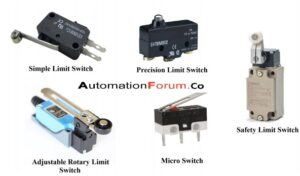
Limit Switch, Image Source: Automation forum

What is the function of Limit Switch?

Limit Switches are activated by the presence or absence of an object or by the movement of machinery.

The primary function of a Limit Switch is to open or close a contact in a circuit when a certain distance covered by a motor-operated device has been reached. Limit Switch is applied in the control circuit for different purposes like slow down, reverse, or stopping the operation of the machinery.

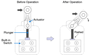
A Limit Switch consists of an actuator connected to an electrical switch. As soon as a moving machine or a moving machine part strikes the actuator, the operation of the Limit Switch begins and actuates the switch. As a result, the Electrical circuit controls the machine and its motion.

Limit Switches can be used either as a control device for standard operations or as emergency switches to stop the inappropriate functioning of the machine.

Components of a Limit Switch

A Limit Switch is a detection kind of switch inside a metal or resin casing. The outer case is necessary to protect the switch from dust, dirt, external forces, moisture, oil, etc.

The main components of Limit Switch are:

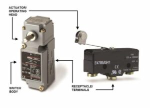
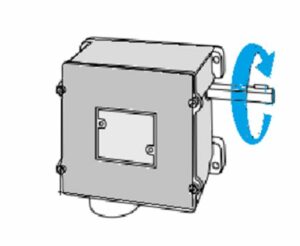
  • Actuator: This is the part that comes in physical contact with the moving machine or machine part. It is constructed with tough material to withstand a significant amount of force and shock.
  • Operating head: Sometimes, the actuator is connected with an operating head which converts the rotary, linear, or perpendicular motion of the device into an electrical signal to operate the switch.
  • Switch body: It refers to the whole electrical contact mechanism.
  • A series of Electrical terminals: Screws or screw/clamp assembly essential for wiring purposes.
one
wo

Components of a Limit Switch, Image Source: @pub/@electrical

What triggers a Limit Switch?

Limit switches are triggered by a physical force applied to the actuator of the switch by machinery. The cams connected to the actuator shaft readily activate the switch.

When the product comes to physical contact with the actuator of a Limit Switch, this physical touch is converted into an electrical signal which activates or deactivates the electrical circuit within the switch. As the product moves away, the actuator and the switch go back to the normal position.

Different types of actuators are used in Limit Switches depending on different applications. Actuators are mainly selected considering certain factors like travel distance, shape, speed, the direction of the machine part being used to trip the Limit Switch. The main types of actuators are flexible rod, plunger, and roller lever.

limit struct img3 1

Function of a Limit Switch, Image Source: omron.com

What is a valve position switch?

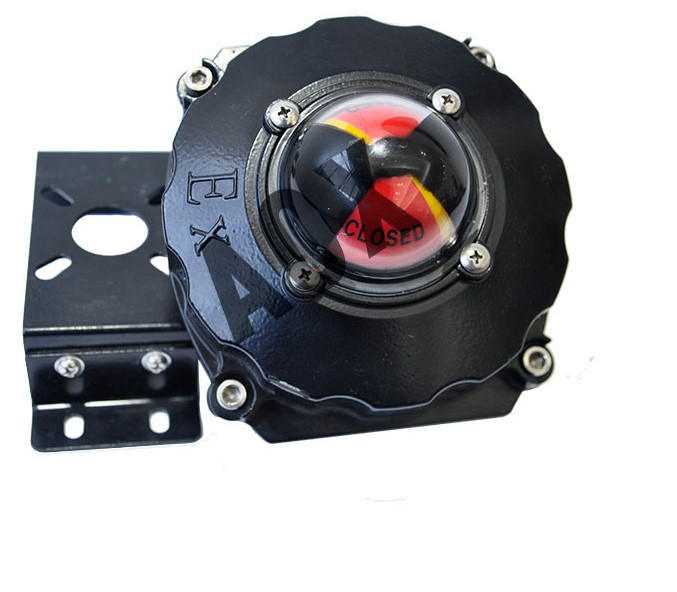
Valve position switches are electrical switching devices associated with a Limit Switch for giving an easy visual indication of the current position of the valve assembly.

Valve position switches inform us about the position(open, closed or in an intermediate state) of the valve in the form of continuous signal. These switches can be fixed directly on the actuator of the valve. They can be used in combination with a valve positioner.

Limit switches are activated by the physical touch experienced by the actuator of machinery. The mechanical motion experienced by the actuator plunger is converted into electrical signals which in turn change or regulate the make or break state of the circuit.

limit switch valve

Valve position switch, Image credit : aoxactuator.com

How does a Rotary Limit switch work?

Rotary Limit Switches are generally used to control shaft revolutions or to limit movement based on the rotation angle of industrial machinery.

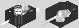
A Rotary Limit Switch is an assembly of gears and cams to trigger a microswitch when the preset number of revolutions has been reached. Here the working principle of a worm drive has been followed. Gears are linked to a cam mechanism that rotates entirely depending on the central gear.

In a Rotary Limit Switch, a shaft must turn a predetermined number of revolutions before the contact changes state as in cranes.

Rotary Limit Switch consists of a shaft that is connected to the shaft of a gear box through a coupling. When the shaft of the gear box rotates, the shaft of the Rotary Limit Switch also rotates. Cams are mounted concentrically with the gears, so as the gears turn, the cams rotate, and rocker arms attached to the cam lobes trip switches at set positions.

limit switch 6

Rotary Limit Switch, Image Source: Motion control tips

Generally the input gear is a worm gear but planetary and spur gear are also used. Gear type is decided depending on the requisite gear ratio. The limit at which the switches are activated depends on design of cam lobes and on the ratio of the input gear.

limit switch 9

Rotary Limit Switch, Image Source: ohmic-local-manufacture

At least two cams and two switches are essential for a Rotary limit Switch assembly, one for each end or upper and lower limit of travel of the machinery.

Frequently Asked Questions (FAQs)

Q.What are the applications of a Limit Switch?

Ans: Though Limit Switches are available in many forms and perform different functions but in general they are electromechanical switches which are operated by the presence or motion of an object.

Some applications of Limit Switches are as follows:

  • In material handling application giving indication of passage of material from one platform to another.
  • Widely used in overhead cranes
  • Used in automatic machinery.
  • Used in High speed equipment.
  • Also used in machine tools and rusticate the travel of a machine axis.
  • Used to control the liquid level in pumping system.
  • Used in elevators and conveyors.

Q. What are the types of Limit Switches?

Ans: Limit switches are classified based on motion of the lever and type of actuating mechanism.

Limit switches are classified based on the actuating mechanism as:- Lever type and Plunger type. Based on the type of motion the limit switches are classified as Rotary motion type and Linear motion type.

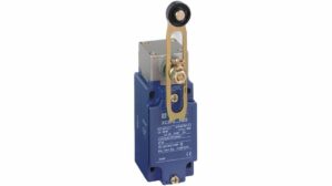
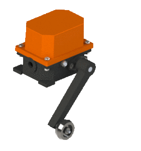
Lever Type: A switch with lever type actuating mechanism has a lever attached to it. When the moving machinery or equipment comes in contact with the lever it pushes the lever, which in turns connects or disconnects the electrical circuit. The contact point of the lever with the machinery is normally provided with a roller. The lever is also provided with a retrace mechanism to bring back the lever to original position once the machinery/ equipment is removed from the position. It normally finds use in lifting cranes, lifts etc.

leverlimitswitchanimation
Lever Limit Switch
Image Credit: anandcontrols.in

Plunger Type: A Push or plunger type Limit switch on the other hand, gets actuated when the machinery or equipment presses against the push button provided in the limit switch. This is the most common type of limit switch which are available in a car or a refrigerator door. A typical push type limit switch is shown below.

Push Type
Push Type Limit switch
Image Credit: instrumentationtools.com

Rotary Motion Limit Switch: A rotary motion limit switch is normally attached to a rotating device such as an electric motor. It detects the rotary motion of the shaft or device connected to it. On achieving specified number of rotations or in other cases angles set for rotation, the limit switch gets activated. They are normally used for rotating service such as crane hoisting or in service where linear motion is translated to rotating motion.

Rotary Motion
Rotary Motion Limit Switch
Image Credit: instrumentationtools.com

Linear Motion Limit Switch: The most common type of limit switch used in the industrial application is the linear motion limit switch. They detect the linear motion of the equipment or machinery and find wide sue in packaging, manufacturing, motor control and other consumer applications.

Do We Use Ac Or Dc:Interesting Aspects on Different Industries and Home

276169274 822a7f2693 b

Electricity has two forms: alternating current AC and direct current DC, so there is always a comparison between AC or DC, Tesla has supported AC where Edison has supported the DC mode of electricity.

Although alternating current AC is comparatively more used than that of DC, this article will discuss where do we use AC or DC in different aspects.

Uses of Alternating Current:

Alternating Current (AC) has its benefits as well as drawbacks. There are different applications where AC is used over DC as per the requirement of operation.

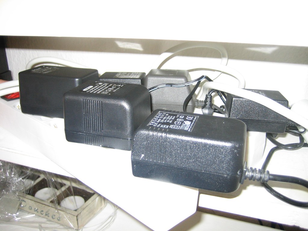
Power Adaptors
Image Credit: “Power Adaptors” by schoschie is licensed under CC BY 2.0

Let’s discuss where do we use ac or dc, The following is where the AC power supply is used :

  • Alternating current is generally used in industry for transmission and generation of electricity as the generation of alternating current (AC) is much easier than that of Direct Current (DC) for high voltages, as AC has better efficiency than DC.
  • DC loses more power to heat relative to AC which causes a higher risk of producing fire, burning appliances, high-cost maintenance and complicated conversion between high voltage and low current to low voltage and high current in DC using Transformers, so in place of DC most industry prefers AC.
  • In the household, there are many appliances that convert electrical energy into mechanical energy that devices use AC power supply such as dishwasher, refrigerator, washing machine, etc.
  • The AC motor (uses AC as power supply) depends on the reversing magnetic field produced by alternating current. The DC motor requires brushes to make electrical contact with the moving coil. In contrast, an AC motor does not require it, which makes AC to operate AC motors easily.
  • Generally, all kind of transformer uses AC supply as DC supply does not work with transformers. The DC Transformer is there but designing that kind of transformer is complicated than a regular transformer.
  • AC induction motors are used for large-sized industrial Servo Motors, which often require variable frequency drives to allow control of their speed.
  • High Voltage AC is more efficient than DC for sending electricity over a considerable distance; that is why high voltages from power plants are supplied to the home, which can be easily converted to required voltage or current by using a transformer.
  • An induction motor or heater uses AC as supply; if DC supply is used in induction motor, commutator and brush will be required as extra part in motor, which will wear out very easily the motor. The need for the replacement of the brush or commutator will be very much frequent. Using the AC in the induction motor makes the overall cost less, the motor will last longer. Maintenance will not be required as a DC induction motor. As for induction heating, the heat is generated by Eddy current, which requires an alternating current eddy current that is not present in DC.
  • The air conditioner uses AC as a supply instead of DC, and there is some air conditioner that uses DC, but that air conditioner has Limited power applications. Although the Air conditioner uses DC, the main supply is always an AC supply. The inverter of the Air conditioner converts the AC to DC then uses it.
  • For home and residential applications, only a single-phase AC power supply is used. A three-phase AC supply is used as 3 phase supply for commercial and industrial facilities to accommodate high loads better. A single-phase AC supply is used when loads are lighting or heating, and a three-phase AC supply is used for large machines for electric motors.
  • The power factor of 3 phase AC motors is high, which means they require less voltage for the load. The motor that uses a three-phase can start with only a power supply. It can even reverse its direction if needed, whereas the motor that uses a single-phase AC cannot start itself; they require an external power supply or device for starting it.
  • Use of AC Motors is preferred for Air Conditioning compressor, power drives, hydraulic and irrigation pump etc.
  • The airline industry uses AC as the main electrical power supply over DC supply. If needed, the AC will be converted to DC using a transformer rectifier unit for the airline. The engine-driven alternator supplies containers powered to AC essentials by an AC bus, where some large turboprops have both AC or DC generators.
  • 3 phase synchronous motor is used for application which needs operating at constant speed such as air compressor motor-generator Rolling Mills paper and cement industry etc
  • Single-phase synchronous motor is used in clocks teleprinters and every kind of timing device, recording instrument, sound recording and reproducing instrument.

Use of Direct Current:

Direct current also has its benefits as well as drawbacks. There are different applications where DC is used over AC because of its efficiency or the specific operation’s requirement.

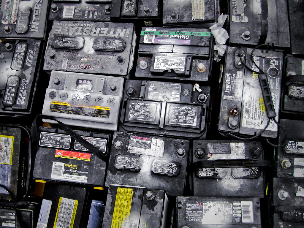
Batteries
Image Credit: “Batteries” by spatulated is licensed under CC BY 2.0

Here are the following where DC supply is used :

  • Different devices or appliances (mainly digital electronic appliances) at home use DC as a supply, such as a microwave oven, computer, phone, etc.
  • DC has better transmission than AC due to laser losses in AC
  • DC is mainly used with appliances that use batteries. Every charger adaptor used in our houses is a converter from AC to DC, such as phone chargers, flashlight chargers, televisions, computers, hybrid or electric verticals, etc.
  • DC is generally used for long-distance transmission. As the transmission of AC power is very much Limited to short or medium range distance maximum distance, AC power cover is 800 km approximately.
  • High voltage DC has better transmission than AC due to laser losses in AC.
  • For local generation DC is much better than that of AC as conversion between AC to DC is expensive.
  • Both rechargeable and non-rechargeable types of battery supplies are always DC rechargeable battery need DC for recharge.
  • Currents generated from solar panels are the DC units of solar panels; an inverter is used to enable DC to AC conversion.
  • Where stable speed torque or operation is required, the steady energy flow of DC is used for operation off Motors.
  • DC motor is used for steel mill rolling equipment, paper machine, etc.
  • Series DC motors are used for heavy-duty applications such as electric locomotives, lifts, cranes, Steel Rolling Mills etc.
  • DC shunt motor is used for operating appliances or devices at constant speed such as vacuum cleaners, woodworking machines, conveyors, elevators, grinders, shafts, small printing presses etc.

AC Circuit Vs Dc Circuit:Comparative Analysis On Different Aspects

In the AC system, voltage and current change their polarity and magnitude at a specific interval of time; the AC system is widely used because of its advantages.

This article will discuss the Ac circuit vs DC circuit, the advantages of AC over DC, etc.

Why is AC used over DC?

The use of DC is very much limited to some devices; for more significant scale generation, distribution, transmission, etc., AC is adopted. AC has been in use for ages.

Advantages of AC over DC:ong>

ACDCAC can be stepped down or stepped up easily using the various methods or by using Transformer as Transformer works for AC properly. Ac can be easily scaled to the desired level with very low energy loss.DC cannot be stepped down or Step Up easily as the Transformer does not work appropriately with DC.
AC generation costs less than that of DC generationGeneration of DC is costlier than that of AC generation
AC can be converted easily into DC using a rectifier, filter, etc.DC to AC converter is complicated. 
AC devices or the motor which uses AC as a power source are economical, robust, and durable. DC devices or instrument which uses DC as a power supply are costlier and less durable. 
The maintenance cost of AC equipment or device is very much cost-effective Maintenance of DC equipment or devices can cost much more than that of AC devices or types of equipment.
At high voltages, AC can be generated.Due to commutation difficulty is a DC cannot be generated at high voltages.
Switchgear is simple for AC circuits.Switchgear is complicated for DC. It required additional measures to work properly.
AC Transmission and distribution are economical as well as loss in AC power due to transmission is relatively lesser than that of DC transmission.DC Transmission and distribution are costlier as well as loss in DC power due to transmission is relatively more than that of AC.
AC generator has high efficiency.The DC generator is less efficient than that of an AC generator.
AC does not have to face much of electrolytic corrosionDC has more Electrolytic corrosion
Arc generated in AC is lower in strength and can be self-extinguished as AC has zero crossing in its cycle.Arc generated in DC is much stronger and cannot be self-extinguished as DC does not have any zero-crossing.
The AC Induction motor  is easy to use or maintainThe DC Induction motor, for proper working, requires a commutator, brushes, and switches.
ac circuit vs dc circuit
Image Credit : AC signal and DC pulsating signal By Omegatron – Own work, CC BY-SA 3.0,

Other Differences between AC and DC are:

AC Circuit vs DC Circuit:

ACDC
An AC circuit current its direction (or polarity) and its magnitude periodically.DC circuit current flows only in one direction; only magnitude can vary polarity of voltage, or current does not change with time.
AC signal has a specific frequencyDC does not have any specific frequency to define it. 
The amplitude of the AC signal changes continuously.The amplitude of DC can change, but polarity remains fixed.
AC cannot be used to directly for electroplating, electrolytic or electrochemical processDC can be used directly for electroplating electrolytic or electrochemical process
AC Motor’s speed cannot be controlled easilyDC Motor’s speed can be controlled easily

Disadvantages of AC:

DC Circuit Breaker vs AC Circuit Breaker

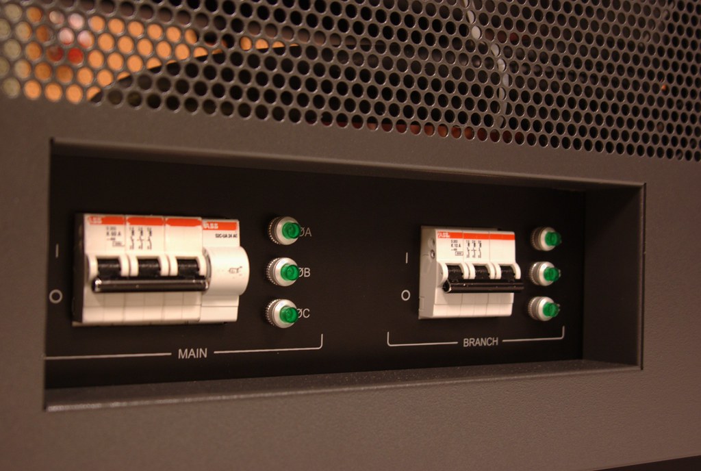
A circuit breaker is a switching device designed to protect any circuit or device from getting damaged. Ac and dc circuit breakers are both used in the different electric circuits.

SC5832 Circuit Breakers
Image Credit: “SC5832 Circuit Breakers” by vaxomatic is licensed under CC BY 2.0
DC Circuit BreakerAC Circuit Breaker
The DC circuit breaker uses a thermal protection principle where the overloaded current is slightly larger than that of the standard current for the highly overloaded magnetic protection principle. The AC circuit breaker uses magnetic protection and thermal protection principles. 
DC circuit breakers can be used to protect the main circuit or a single load that uses a DC source. AC circuit breaker is used with a circuit or device that uses an AC source for power. 
As in the DC circuit, the voltage is continuous, and the arc is constant, so it is difficult to disconnect from the circuit. The AC circuit breaker easily gets disconnected from the circuit. 
Extinguishing the arc is relatively poorer than the AC circuit breaker as DC does not have a zero-crossing point. Extinguishing the arc is easy with an AC circuit breaker as ac has a zero-crossing point with every complete cycle. 
The extinguishing device is mainly magnetic blowing typeThe Arc extinguishing device is mainly grid type
AC circuit breaker cannot be used in place of DC circuit breakerDC circuit breaker cannot be used in place of AC circuit breaker as AC voltage or current may have a different effect on the DC circuit breaker
DC circuit breaker needs extra Arc extinguishing measures as DC cannot be self-extinguished. DC needs to be extended, and additional mechanisms such as DC Arc can only be extinguished by cooling or mechanical introduction. In AC Arc, interruption is easy as voltage and currents are not in steady-state, so the AC circuit arc is weaker than the DC circuit arc, so no additional measures are required. 

How To Solder a Gate Valve: The Correct Way and Solved Problems and Facts

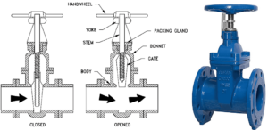
pic 1 1 300x146 1

Gate valves are generally made for shut-off, and you find them in almost all plumbing applications from industrial to water supply at home or in gardens.

Needless to say, the same applies for home fluid plumbing as well. To solder a Gate valve following steps are to be followed:

  • For smooth functioning and cost-effectiveness of the fluid pipelines, proper soldering of a Gate Valve is mandatory.
  • Ensure that the whole piping system is free of any fluid(or water in case of home plumbing) by closing the main valve and draining the residual fluid.
  • Before you start the soldering job, ensure the valve is in close condition.
  • Measure the length of the Gate valve accurately because that much portion of the pipe has to be cut (generally ½ to ¾ inch depending upon the size of the valve and piping)
  • Next, using a pipe cleaner, clean the main pipe as well as the Gate valve. The ends of the pipe must be free of dirt. Cleaning the inside of the pipes is as important.
  • Using a flux brush apply some paste flux on both the ends of the main pipe and along with the Gate valve.
  • Now insert the cut ends of the main pipe inside the Gate valve properly. Some resistance should be expected.
  • For the final step, get the solder wires. Using a propane torch heat both the ends to be soldered. Keep the bent end of solder wire near the adjoined area so that it melts around it properly. Same process is applied for the other end also.
  • Allow to cool down the soldered ends and remove the excess amount with the help of a rag.
  • The Gate valve is now fixed in the piping system.

Do you Solder a Gate Valve open or closed

Generally, each manufacturer has a recommendation for open or closed state of the Gate valve at the time of soldering.  Therefore, it is beneficial to go through the manufacturer’s guidelines before starting the work

As per the experts’ opinion Gate valve should remain in a closed state at the time of soldering. Gate valves are most widely used in industrial sectors for starting or stopping a flow. Gate Valves are not suitable for regulating service.

Before installation of a Gate valve, detailed verification of operating fluid, environment, pressure, and temperature are necessary. The installer should ensure the limit of pressure and temperature that may be sustained by the Gate valve.

  •  
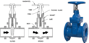
solder a gate valve

Image credit: Gate valves https://hardhatengineer.com/gate-valve-types-parts/

How do you Solder a copper gate valve?

The soldering flux paste used for copper soldering is Superior No.135 (rosin/petrolatum). This flux provides protection to the soldering area and is ideal for copper soldering.

The basic steps of soldering copper gate valve are as follows:

  • Collect all the necessary tools at one place like a propane torch for heating. Arrange tinning flux or paste flux and lead-free solder.
  • Cut the pipe with a tube cutter.
  • By inserting and twisting a reaming attachment, the inside burrs at the cut ends of the pipe can be removed.
  • Clean dirt and corrosion from the outside pipe surface with an emery cloth.
  • Inside portion of the pipe should also be cleaned using a wire brush.
  • Brush an even layer of flux over the pipe surface and inside the valve, the same way as you apply butter on a toast.
  • Heat the joint with the help of a propane torch evenly and allow itthe solder to meltso that it flows into the joint and seal it. A full joint on all sides should be obtained.

How do you Solder a brass gate valve?

The main difference between copper and brass is that brass requires much more heat for the solder to work efficiently.

As an alloy of copper and zinc, Brass is companionable with copper. Solder adheres to copper as well as brass properly, and fittings are generally molded with slip joints and can be easily soldered to the pipes.

More often than not, you would encounter a brass valve while looking for a valve to solder in a copper pipe. The amount of heat required to melt the flux inside a brass valve is around 5-6times that of a copper valve. Hence, in order to ensure that the flux has properly set in between the piping and the valve, sufficient time must be provided for heating.

What position should a gate valve be is to be soldered?

Gate valves are suitable for all types of applications, both above-ground and underground installations.

Most convenient position for all models of Gate valves (inclined, horizontal, and vertical) with the flow in both directions is installed horizontally with the hand wheel pointing in the upward direction.

The position should be selected in such a way so that it can be easily accessible during operation, inspection, and maintenance. A horizontally placed Gate valve is always easy to operate and also easily accessible for maintenance. However, there are some industrial applications where installing a Gate valve vertically downward is preferred. This is to ensure that the valve remains in an open position, even if the lock-nut holding the gate to the spindle has broken and the gate has fallen off.

How to Solder a ball valve?

Soldering a ball valve is a very familiar and frequently used project in plumbing. The soldering technique of ball valves is not a complex process and can be performed without any professional guidance.

To perform correctly, one should have proper knowledge of the whole process. The step by step process for soldering a ball valve is as follows.

  • Assemble all the necessary tools like tinning flux, lead-free solder, a ball valve, pipe cutter, pipe cleaner, heat source, safety gloves, etc
  • Cut the pipe with the help of a pipe cutter and clean the two ends thoroughly.
  • Apply a layer of flux with the help of a brush on the two pipe ends and inside the ball valve also.
  •  Place the ball valve in between the cut ends of the pipe,
  • According to the manufacture’s guidelines, keep the ball valve in the open or closed position during soldering.
  • Apply heat to the pipe and ball valve area. It is important to note that the body of the valve should not come under direct fame as otherwise, the nylon seal inside the valve may be melted.
  • Apply the solder on adjoined areas and continue heating until the solder melts and fills up the gap.  Let the pipe cool down.
  • One of the most commonly asked questions is whether to solder ball valves in an open or closed position.Both open and closed option is suitable for soldering ball valves. But it is advisable to solder ball valves in a closed position to avoid the chance of formation of blowing gas bubbles in the joint.
  • In the closed position, air generally exits the pipe. On the contrary, there are certain risks involved in soldering a ball valve in an open position. In the open position, water may be trapped in the seals or pipes, which get convert into steam due to the application of heat during soldering. Steam may blow out the seal causing damage to the valve.

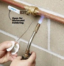
ball valve

Image Credit: Soldering of Ball valves https://www.pressreader.com/usa/the-family-handyman/20180501/282437054662433

Can I Solder a closed ball valve with water on the other side?

Soldering a closed valve with water on the side is beneficial.

It is possible to solder a ball valve with one side in live condition. The application of heat during soldering should not be too high to melt the seals. Otherwise, it may result from a bleeder port. Wrapping a wet rag is always suggested for better results.

To remove the heat produced during soldering, it is normal practice to wrap a wet cloth to remove the heat away. If water is present on the other side, it is beneficial as it will help to remove the heat generated by the soldering process. Care must be taken so that you don’t heat the side with water as it might lead to vaporization of water leading to the blow-up of the ball valve seal.

Can you Solder near Teflon tape?

Teflon tapes or PTFE (Polytetrafluoroethylene) is a common name in plumbing, most widely used for sealing pipe threads. Breakdown may occur in contact with open flames.

The applicable temperature range of a Teflon tape ranges from -268°C to+260°C. Generally, a Teflon tape can withstand temperatures upto 260°C, rate of decomposition is slow up to 400°C. During Soldering near PTFE tape, this temperature range should be maintained.

What is used in Soldering?

Soldering is a joining process most widely used in manufacturing electronic equipment, joining and sealing pipes in the plumbing trade, and also in the jewelry business.

The list of essential items required for any kind of Soldering process are:

  • Solder: The main ingredient of the Soldering technique melts to join different types of metals. Traditionally an alloy of tin and lead (Sn 60% & Pb 40%). Nowadays, due to lead toxicity, most of the solders are lead-free, which is an alloy of tin with other metals like copper and silver.
  • Soldering Iron: It is a handheld tool that is the main source of heat to melt the solder. Generally, it has a pencil-like shape and very comfortable and easy-to-handle tool. As per the requirement, it may also be available as larger solder guns.
  • Soldering Flux:To achieve a good solder joint, a fresh and proper chemical flux is essential. Flux removes oxides from both the metal surface and solder surface so that molten solder can wet the clean metal surfaces to be joined. Resin, Organic, and Inorganic are the different types of flux used as per the requirement.

Soldering valve to copper pipe

Soldering a valve to the copper pipe can be tricky or an easy task at the same time.

The basic steps and precautions that are to be taken for proper soldering of a valve to a copper pipe are as follows:

  • The workmanship of an effective Copper pipe soldering depends largely on sticking to the basics, which are: – right preparation, right tools, and rights methods
  • Get all your tools in places like the flux paste, the propane torch, the solder, a piece of sandpaper, the pipe cutter, and of course, the valve and the pipe.
  • If the soldering is in a live line, ensure the line is drained properly and the source of inlet water is isolated. Then cut the pipes with the pipe cutter.
  • Once the pipes are cut, it is necessary that the surfaces at both ends of the cut pipe are properly rubbed with the abrasive sandpaper so that a shine appears over the surfaces to be soldered.
  • The next step is to dry-fit the valve, and it is to be ensured that the valve fits into both sides snugly.
  • Apply the flux properly on both the surface as you apply butter to a toast!!! And install the valve.
  • Before you start heating, ensure the valve is at least partially open. This is done so that if there is any residual water left in the pipe, it doesn’t pressurize the system and crack the soldered joints.
  • Lit up the propane torch to heat the surface to melt the flux within.
  • Once the flux has melted, the primary sealing is done. The next step is to bring in the solder.
  • Continue heating with the propane torch to melt the solder so that it is assimilated into the gap between the pipe and the fitting, thus providing a leak-proof fitting.
  • Once it is ensured that the solder has got into all the cracks and crevices of the fitting, let it cool down before being put into service. This is to ensure that the newly soldered joint does not crack due to thermal shock.

How to Solder brass valve to copper?

It is not a big deal to solder brass valve to copper pipe if we are aware enough about certain facts. The temperature of the pipe should be hot enough at the time of applying the Solder.

It is advisable to perform soldering of brass valves correctly in the first attempt because redo may create the problem. When the metal surface reaches the accurate temperature, the plumbing solder flows into the joint between the pipe surface and valve by capillary action and, after cooling, results in a watertight seal.

To avoid a leaking joint, make sure that the moisture inside the pipe can escape completely when it turns into steam.

The same steps are followed as discussed above for soldering valve to copper pipe.

HDMI CEC vs ARC: In Depth Comparative Analysis and Facts

HDMI CEC vs ARC

This article shows an overall comparison between HDMI CEC vs ARC. CEC is the “Consumer Electronics Control,” a feature of HDMI that uses a single remote controller to control the HDMI cable connected devices.

We have learned already that HDMI ARC (Audio Return Channel) is also a particular function of HDMI. It is a port in the systems that allow high quality audio transmission. Both HDMI Arc and HDMI CEC use a single cable but for different purposes. Just like the name, HDMI CEC caters to the control of electronic devices.

HDMI CEC vs ARC

What is CEC in HDMI?

As mentioned above, HDMI CEC is the abbreviation of Consumer Electronics Control. HDMI controlling devices are commonly known as CEC. A wide range of professional and consumer AV devices support this function.

Different electronic brands have given various names to CEC. For the brand Sony, it is “BraviaSync,”; for Philips, it is “Easylink,” for Samsung, “Anynet+, LG-“Simplink,” etc. All of these components work similarly, but one is not compatible with the other. HDMI CEC allows HDMI AV devices to communicate with each other.

What is the utility of CEC?

When we have to deal with multiple HDMI AV systems and manage them with an individual remote control, we can use the CEC feature. Besides passing video or audio, CEC helps all the devices to interconnect.

HDMI CEC establishes a back and forth connection between the TV and its HDMI joined peripherals. While the TV can control those devices, the devices also get some control over the TV. For example, we can control a gaming console through the TV remote. Similarly, the other systems can also change any TV input. 

Explain the differences between HDMI ARC and HDMI CEC.

Following are the major differences between HDMI CEC and HDMI Arc-

ParameterHDMI ArcHDMI CEC
PurposeWe use HDMI Arc or Audio Return Channel for better audio experience.HDMI CEC eases the mutual control procedure between a device and its HDMI connected systems.
Method of usageHDMI Arc is a special port in the primary device. We can connect the soundbar or speaker with it so that the main device sends the audio back to the soundbar or speaker and provides good quality sound.If HDMI CEC is enabled in a component, it can control the devices connected to its HDMI port and vice-versa. Different brands have different methods to enable their CEC function.

Read more on…HDMI Vs HDMI Arc: Exhaustive Comparison and Detailed Facts and FAQs

HDMI CEC vs ARC- FAQs

Is HDMI ARC the same as HDMI CEC?

HDMI Arc and HDMI CEC are two separate entities. Arc is an enhanced function of HDMI technology. On the other hand, CEC or consumer electronics control is a single remote control for operating all HDMI systems. 

HDMI Arc ( Audio Return Channel ) is a specific port in HDMI TVs or other equipment that feeds the digital audio stream back to the soundbar. Thus we can play audio through an external sound system. CEC is a channel that controls input, power on and off, volume, play, pause, etc., in HDMI devices combined.

lI7bAnPiyjo8PoH qpKM2swMuRgL5Teo4FYpwuN6 Z2DnrHWaOQo0a6yTk5FZZ3D6YNw98SPqABKrXFeKjsZ7DsPdOjjr7D06D4IrnJ98
Image credits : nakamichi-usa.com

Does eARC need CEC?

HDMI eArc or enhanced Arc is an even better version of Arc technology. The latest 2.1 standard HDMI has the eArc function implemented in it. HDMI eArc provides greater speed and bandwidth for the best audio.

HDMI eArc relies on CEC to automate remote control commands. The HDMI eARC only supports the discovery and set-up of eArc link, lip-sync, etc., operations. HDMI eArc was made to skip volume control commands which CEC performs for better usability. So, to use an eArc device, we must enable CEC as it is part of Arc discovery. 

dV B1Z4OcUuo4YD AQW354N6fAKytoNZDp59Q6aXlwzXtaq9C8ZUUU6FfOUTVl1gtPLgpgAtN8c3wJwtRozPnuIMptcn3NEFCxaRn9cMAnWL8yEt R3571aScE0vTNyd8de0c9O3
HDMI eARC specifications; Image Credit : hdmi.org

How can I set up HDMI Arc and CEC?

All the TV instruction manuals come with the setup process of CEC. We can use the TV remote and browse through the options to enable the CEC mode. Some TVs are by default set in CEC until we manually change them.

Every brand has a specific way to set the CEC function up. So we can not generalize the method. We can take the example of Samsung ( Anynet+) CEC here. Go to the Home screen through the remote, then to settings and select the “Anynet+” to turn it on. Finally, connect and turn on an HDMI device through a cable.  

How to enable Anynet+ in Series 6 4K UHD TV(KU6470)? | Samsung India
Samsung CEC( Anynet+) : Image source: samsung.com

Do all HDMI TVs need CEC?

CEC is a prevalent feature of TVs and other peripheral equipment. It allows two-way communication between the TV and the other devices connected to the TV’s HDMI port without the need for universal control.

CEC wiring is a must in modern TV sets , but optionally we can skip using it. There are many functions like one-touch play, one-touch record, routing control, deck control, system audio control etc. that can be done through CEC in TV. Though CEC can ease the usage, it is usually disabled by default. 

Does HDMI cable matter for CEC?

Consumer Electronics Control or CEC in HDMI equipment facilitates one stop control for all HDMI connected devices. It is just a special command that is independent of the HDMI cable.

CEC feature was first introduced in HDMI 1.0 and later updated in 1.3 standards. The CEC feature in HDMI is just used for the controlling purpose. It is implemented with TV remote settings. It has nothing to do with the cable. Any general HDMI cable works fine for CEC.