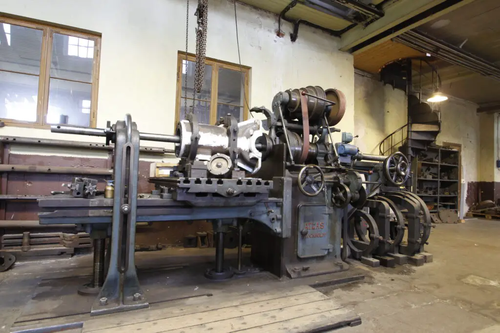
Milling Machine Working:Step By Step

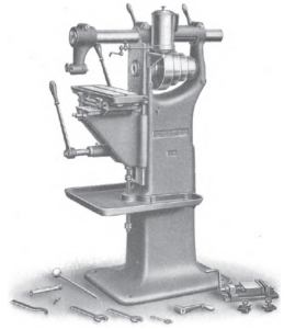
Practical Treatise on Milling and Milling Machines p051 300x139 1

In the article briefly we are going to discuss the topic about the “Milling machine working.” . Milling machine working principle is needed to operating the machine tools.

To get the right features of the material is following the steps:

In milling machine process the metal is removed by followed the steps to creating different types of features to cutting the excess unwanted materials.
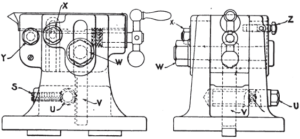
milling machine working
Milling machine
Image credit – Wikimedia Common

How a milling machine tool is working on a tool is briefly discusses in below section,

Time of loading or unloading:

For the installation of the workpiece which is attached to the milling machine tool and then whole setup is again fixed with the fixture and in the final of the process the final product need to unload. The time of loading or unloading is depended on some parameters. The parameters are size of the workpiece and fixture, complexity and weight of the fixture and workpiece.
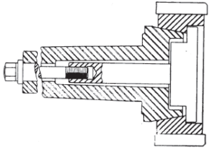
Milling machine working
Image Credit – Wikimedia Commons

Cutting time:

From the term of the workpiece we could easily understand that the time required for the edges cutting of the workpiece and the fixtures for each and every operations of the milling machine tool. The cutting time can be explain as the required time which is calculated the whole amount of the length which is divided by the feed rate for the particular milling operations that is the speed to the relative  cutter of the workpiece or fixture.

Idle time:

The term of idle time means the time which is not productive. The idle time can be explain as the time period of the milling machine operation process which is not engaging the cycle of the process to the fixture and unwanted excess amount of material is removed and get desired shape and size of the material’s part.

The idle time of the process is also included adjusting the setting of the machine, movements of the tools into the features, changes of the machine tools and also approaching the work tool and after that workpiece is reacting.

Read more about The correct way and solved problems and Facts

Time of the tool replacement:

At the last of the process the steps is happed that is the tool replacement. A particular time is needed to replace the tool of the milling machine. The time of the tool replacement is exceeding the time period of the tool that is the main reason behind the worn to cut the effectiveness. The time of the tool replacement is not performed each and every time process cycle but it’s only happed when the tool is reaches to its life time period.

For calculating the time period of the tool is replacement with the time and it is adjusting for making the particular single part which is multiplying with the frequency, in this way the cutting time of the tool is divided by the lifetime of the work tool.

The milling machine mainly a process of material removes. In any field of  production engineering industry there a lots of machine and machine tools are used to do a wide range of operation in the work piece among them milling machine is. By the help of this machine tool a wide range of cutting can so easily without facing any difficulties in the work piece or fixtures.

Milling machine such as operation by which we can easily work with asymmetric material. The asymmetric materials contain a lot of features that can be pockets, internal threads, making surface of the material flat, external threads, revolutions making of the surfaces of workpiece, 3D surface counters, holes or sockets. It works against the fed which is a rotating cutter with multipoint. The multipoint cutter is rotates in a higher speed at the speed of removing the workpiece material is too high.

Required a certain time period to achieving the fixed features of the workpiece with in a cycle time included the setup of the initial time period for each and every steps of the milling machine tool.

Milling machine types:

The milling machine tool is one of the most useful machines among the all machine tools used in the production industries. It is the main operation of machining process. The process is working to feed the fixture besides using a turning tool. Several edges with cutter is contains by the turning cylindrical tool.

In a production industry by the capacity of metal removing rate mainly five types of milling machine is classified. The classifications named are,

The classified milling machines descriptions are given in below section,

Knee and column type milling machine tool: One of the most common and oldest milling machines is knee and column type milling machine.

These are one of the most common used milling machine tool in the industry of the production.

This also can be categorized in four parts. They are,

  • Vertical milling machine
  • Universal milling machine
  • Hand milling machine
  • Horizontal milling machine

Planer milling machine tool: The planer milling machine is almost same as the fixed bed type milling machine.

Fixed bed type milling machine tool: In this type of milling machine the table is situated directly to the bed of machine tool and attached with head and cutters which help to do the operations into the workpiece.

This type of milling machine tool is also can be categorized in three parts. They are,

  • Simplex milling machine tool
  • Duplex milling machine tool
  • Triplex milling machine tool

Centred machining machines: Now a day the milling machine is worked by the computer. The Computer numerical control machines are gives more accrue and define workpiece. With this versatile machine can be attached and do a lots of type operations like boring, milling, drilling tapering and many more.

Individual type of milling machine tool:

The type of this milling machine tool is given below,

  • Duplicating milling machine
  • Continuous milling machine
  • Planetary milling machine
  • Pantograph milling machine
  • Drum milling machine
  • Profiling milling machine
  • Tracer and profiling milling machine

When the motion of milling machine tool is controlled by the electric the classifications names are maintained in below,

  • Transfer lines milling machine
  • Flexible manufacturing system milling machine
  • Flexible manufacturing cell milling machine
  • Centerd machining milling machine
  • CNC programming milling machine
  • Data input manually milling machine

Uses of milling machine:

A milling machine is a process of machining where material is removed with the help of the rotary cutters. The operation of the milling machine can be done in various directions that could be one or more than one axes, pressure and head speed of the cutter. The milling machine operations can be done in various metals that could be large, small, heavy or light. In below we are going to discuss about the application of the milling machine,

  • Gears which are in various types and shapes are made by the milling machine.
  • In the workpiece slot and grooves are easily made by the milling machine.
  • Complicated shapes are also can be make in the workpiece.
  • Make flat the surface of workpiece and countered surface is also can make with it
  • Slotting is done by this machining process.

Milling machine examples:

The example of milling machine is discuss in below,

Horizontal milling machine: Horizontal milling machine another name is plain milling machine. The horizontal milling machine contains a spindle which is situated in horizontally. The table of this machine can be feed in any direction means it can be feed cross sectional or vertically neither horizontally.
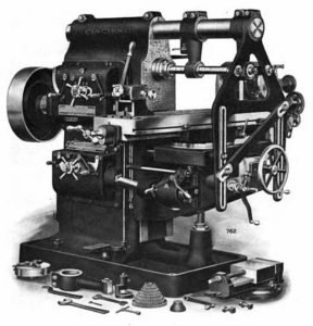
Horizontal milling machine
Image Credit – Wikimedia Commons

In the horizontal milling machine the feed can be done in three dimensions and their little description is given below,

Vertical – In this the table is adjusted vertically.

Cross – In this dimension the table can moves parallel to the spindle of the milling machine.

Longitudinal – In this dimension the table of the milling machine rotate.

Read more about Wing Pulley: What Is, Types, Material, Interesting Guide

Vertical milling machine: In the vertical milling machine the present spindle is situated in vertical position to the table of the milling machine. This milling machine is used to do various operations in the workpiece such as grooving, slot and flatten the surface of the workpiece. The head of the spindle is attached with the column vertically which rotate with a motion angularly.

Vertical milling machine
Image Credit – Wikimedia Commons

Universal milling machine: In the universal milling machine a table is attached with the column. The table can rotate in all motions with a dividing head which can changes all the gears that is the reason the milling machine can do any type of operation into the workpiece and we can get a desired part if the material.
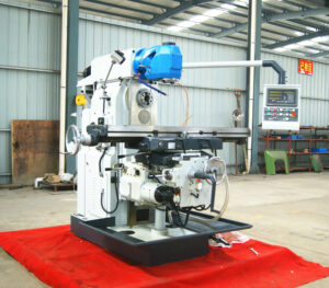
Universal milling machine
Image Credit – Wikimedia Commons

It included some extra attachments’,

  • Rotary attachment
  • Index head
  • Slotting attachment
  • Vertical milling attachment

Planer style milling machine:

Turret milling machine: The turret milling machine is also known as the Bridgeport type milling machine. This is a versatile milling machine tool with the help of it we can proceeds a lot of operation and uses widely in the production engineering.
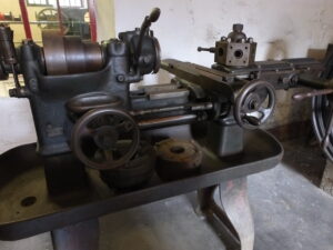
Leeds Industrial Museum machine tools turret lathe 7178
Turret milling machine
Image Credit – Wikimedia Commons

C Frame milling machine: One of the powerful and sturdy milling machine tool is c frame milling machine. Mainly heavy and large size workpiece are can work on it.

Rotary table milling machine

Column milling machine
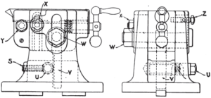
11 Milling Machine Parts:Detailed Explanations

Horizontal milling machine 1024x683 1

In this given article we will briefly discuss about the topic of “Milling Machine Parts”.  The milling machine parts are very useful and uses widely in the work of the production engineering.

In every milling machine tool in generally contain eleven parts.The parts which are carried by the milling machine tool is

A CNC milling machine automated machine tool and CAD software is uses in it.

Milling machine parts
Image Credit – Wikimedia Commons

Milling machine parts and their explanations:

Base:

The base is the part which is placed at the bottom of the milling machine tool. The whole parts of the machine tool are situated in the base.

The base is the foundation of the milling machine tool. The base should be enough rigid and the strength should be enough thus it could hold the whole machine tool.

Material used to make:

The body of the base made with cast iron.

Working Purpose:

1. To hold properly the machine parts of the milling machine tool.

2. Storage of the cutting fluid

3. To absorb the surroundings shocks.

Table:

Table is situated at the saddle’s top portion. The shape of the table is rectangular.

The table is control by the electric power in milling machine. But in common milling machine the milling machine is controlled by both man power and electric power and when the table is controlled by the manpower the hand crank is engaged longitudinally and when the table of the machine tool is controlled by the electric power that time control lever is engaged longitudinally.

Material used to make:

Table of the machine tool is made with cast iron.

Working Purpose:

1. The main purpose of the table is to grip the work piece and the work tool.

2. T slots are also placed in the table of the milling machine tool which are used to hold the work piece and work tool such as jigs and fixtures.

Arbor support:

In the milling machine the tool is support the arbor’s end portion with arbor support’s axle. The support of the arbor is pitch with the help of bearing.

Read more about Timing pulley: What Is,Types,Material,Interesting guide

In the milling machine tool general arbor support is categorized in two types. The one type is smaller diameter bearing which containing the hole diameter maximum up to 1 inch and the another one is bigger diameter bearing which containing the hole diameter is 5.75 inch.

Working Purpose:

1. The oil reservoir is placed in the arbor supports. Lubricate which is comes from the oil reservoir uses in the surface of the bearings.

2. In overhanging arm’s any places the arbor support can be clamped.

Knee:

The shape of the knee in the milling machine tool is almost looks like a human’s knee. The movement of the knee is vertically upon the face of the column. The knee can be moved upward and downward in the directions both.

Material used to make:

The knee of the milling machine tool is made with the help of grey cast iron.

Working Purpose:

 1. Help to hold the feed mechanism which is situated in the table of the milling machine tool.

2. Also helps to grip the saddle.

3. By the help of the knee we could easily adjust the height of the column which is attached with the elevating screw.

Spindle:

The spindle is a machine tool which is act as an intermediate between the knee and table of the milling machine tool. The spindle is placed in the upper portion of the column.

It is actually a shaft which is work in the rotating motion. The spindle can be moved by both manpower and the electric power. The power of the machine tool such as gears, belt and clutches is received by the spindle.

Working Purpose:

1. To horizontally moves the workpiece.

2. The shaft of the spindle is act like as a supporter and positioned for the tool devices.

3. Support the column.

4. The spindle’s face is situated in the tapered machine of the table. The taper of the internal position is situated in the spindle’s face and only permits with arbor or the cutter which is in tapered.

Column:

The column of the milling machine tool is placed the vertical position of the base. The column is one of the most important part of the milling machine tool which carrying all the driving mechanism and also carry the motor.

In the column the v belt is used. The v belt is usually connected the motor and the driving mechanism. The driving mechanism is mainly used to control the speed. It is shaped like a box and all driving mechanisms are situated on it.

Material used to make:

Cast iron is used to make the column of the milling machine tool.

Working Purpose:

1. To hold the driving mechanism and motor.

Ram:

Ram can be defined as if the overhanging arm is present in the milling machine. The ram’s one ending part is attached with the column and other ending part is attached with the head of the milling machine tool.

By the help of the hand lever ram easily can be moved.

Motor:

The power is generated of the milling machine by the motor.

As the human body’s head the milling machine head is also situated at the top. The controlling mechanism is totally handle bf the milling head. The spindle and driven motor also placed in the head.

Machine tool:

The machine tool means the spindle carried the all the components by this the excess amount of material is removed to achieve the desired part.

Machine interface:

The meaning of the machine interface is the operator of the machine components used as machine program of the computer numerical control, load and initiate.

Saddle:

The saddle is placed in the knee and worked as a supporter of a table of the milling machine tool. The dovetail which is placed paralleled to the spindle’s axis. The saddle is present in the horizontal milling machine tool.

Working Purpose:

1.  Guide the table with the help of the top portion of the saddle.

Front brace:

Front brace actually an additional support tool. By the help of the front brace the knee and overhanging arm get extra support.

Arbor:

The arbor of the milling machine meaning into the spindle when the component of the shaft is insert into the horizontal milling machine where tools of machine can be mounted. The component of the milling machine is in various sizes and diameters.

The arbor is present all most every milling machine that could be in end milling, normal milling machine, slitting saw milling cutter, screw, shell cutter arbors and milling cutter arbors.

Working Purpose:

1. Worked as the supporter of the cutters which are used in the milling machining tool.

2. Work tool can be easily hold and move by the arbor.

Milling machine:

In a production industry there a lots of machine and machine tools are present to do a wide range of operation in the work piece among them milling machine is one of the machine tool. By the help of the machine tool a wide range of cutting can be done in the work piece. A lots of operations which are in general very complicated to do on a work piece but with the help of the milling machine tool we can provide this complicated operation too. The operation we could easily do by the machine tool is,

  • Straddle milling
  • Indexing
  • End milling
  • Gang milling
  • Plain milling
  • Face milling
  • Side milling
  • Saw milling
  • Form milling
  • Angular milling or bevel milling
  • Spiral milling or helical milling

In industrial area the milling machine tool mainly used to produce the surfaces .The surfaces which are mainly in form of flat profiled. In other way the slots are made with the help of the tooth cutter which are revolving in multiple.

In the production engineering field there are different types of milling machine tools are present. The types of milling machine which are present in different form is named in the below section,

  • Plain milling machine
  • Knee milling machine
  • Column milling machine
  • Hand milling machine
Hand milling machine
Image Credit – Wikimedia Commons
  • Vertical milling machine
Vertical Milling Machine
Image Credit – Wikimedia Commons
  • Universal milling machine
Universal milling machine
Universal Milling Machine
Image Credit – Wikimedia Commons
  • Plano milling machine
  • Pantograph milling machine
  • Profiling milling machine
  • Planetary milling machine

Frequent Asked Questions:

Question – What is Jigs?

Solution: Jigs can be defined as the device which is helps to grip and locate workpiece of the milling machine tool and control the cutting tool that could be one or more than one.

jig
Jig
Image Credit – Wikipedia

The jigs are also used in the other operations like drilling, tapering or reaming for griping as well as guiding the work tool.

Question: What is fixture?

Fixtures can be defined as the device which is helps to locating and griping the workpiece in the manufacturing operation’s inspection.

Fixture
Fixture
Image Credit – Wikipedia

The fixtures are also used in the other operations like grinding, turning, for griping as well as guiding the workpiece.

The Crucial Role of Logic Gates in Smart Infrastructure

logic gates role in smart infrastructure

Logic gates are the fundamental building blocks of digital circuits, and they play a crucial role in the development and implementation of smart infrastructure. In the context of smart cities, these electronic devices enable the execution of complex logical operations, data storage, and signal processing, which are essential for a wide range of applications, including … Read more

When Do You Need an Amplifier: A Comprehensive Guide to Audio Enhancement

when do you need an amplifier a guide to audio enhancement

When it comes to audio enhancement, an amplifier is often a crucial component in improving sound quality and volume levels. By understanding the key factors that determine when an amplifier is necessary, you can ensure your audio system delivers the best possible performance. In this comprehensive guide, we’ll delve into the technical details and quantifiable … Read more

Understanding Diode Voltage Drop: A Comprehensive Guide

diode voltage drop

The voltage drop across a diode, often ranging from 0.6 to 0.7 volts, is a crucial aspect of diode functionality in electronic circuits. This voltage drop is primarily determined by the diode’s I-V (current-voltage) characteristics, which illustrate the relationship between the voltage and current flowing through the diode. The diode voltage drop is influenced by the diode’s forward current, with a slight increase in voltage drop as the forward current increases. This small increase is often disregarded in practical applications.

Diode I-V Characteristics and Voltage Drop

The I-V characteristics of a diode are typically represented by a graph that shows the relationship between the forward voltage (VF) and the forward current (IF) of the diode. This graph can be used to determine the voltage drop across the diode for a given forward current.

The forward voltage drop of a diode is influenced by several factors, including:

  1. Diode Material: The type of semiconductor material used in the diode, such as silicon (Si) or germanium (Ge), affects the voltage drop. Silicon diodes typically have a forward voltage drop of around 0.6-0.7 V, while germanium diodes have a lower forward voltage drop of around 0.2-0.3 V.

  2. Forward Current: As the forward current through the diode increases, the forward voltage drop also increases slightly. This relationship is generally linear, with the voltage drop increasing by a small amount (typically 0.01-0.02 V) for every tenfold increase in forward current.

  3. Temperature: The forward voltage drop of a diode is also affected by temperature. As the temperature increases, the forward voltage drop typically decreases by about -2 mV/°C for silicon diodes and -4 mV/°C for germanium diodes.

To illustrate the I-V characteristics of a diode, consider the following example:

Forward Current (IF) Forward Voltage (VF)
1 mA 0.60 V
10 mA 0.65 V
100 mA 0.70 V

As shown in the table, as the forward current increases from 1 mA to 100 mA, the forward voltage drop of the diode increases from 0.60 V to 0.70 V. This demonstrates the non-linear relationship between the forward current and voltage drop of a diode.

Diode Voltage Drop in Series with a Resistor

diode voltage drop

When a diode is connected in series with a resistor, the voltage drop across the diode and the resistor will be the same, regardless of whether the resistor is placed before or after the diode. However, it’s essential to consider that the diode’s voltage drop is not a constant value but rather a function of the forward current.

To calculate the total voltage drop across the diode and resistor, you can use the following formula:

VT = VD + VR

Where:
– VT is the total voltage drop across the diode and resistor
– VD is the voltage drop across the diode
– VR is the voltage drop across the resistor

The voltage drop across the resistor (VR) can be calculated using Ohm’s law:

VR = I × R

Where:
– I is the forward current flowing through the circuit
– R is the resistance of the resistor

By substituting the formula for VR into the total voltage drop equation, you can calculate the total voltage drop as:

VT = VD + I × R

It’s important to note that the diode voltage drop (VD) is not a constant value but rather a function of the forward current (I). This means that the total voltage drop across the diode and resistor will vary depending on the forward current flowing through the circuit.

Measuring Diode Voltage Drop

There are several methods for measuring the diode voltage drop, each with its own advantages and limitations.

Using a Digital Multimeter in Diode Test Mode

One common approach is to use a digital multimeter with a “Diode Test” mode. In this mode, the multimeter applies a small voltage (typically around 1 V) between the test leads and measures the voltage drop across the diode when it is forward-biased.

To use the Diode Test mode:
1. Connect the positive (red) test lead to the anode of the diode and the negative (black) test lead to the cathode.
2. The multimeter will display the forward voltage drop of the diode, which should typically be in the range of 0.6-0.7 V for silicon diodes or 0.2-0.3 V for germanium diodes.

This method is generally the most accurate for testing diodes, as it directly measures the forward voltage drop of the diode under a known forward current.

Using the Resistance Mode (Ω)

Another method for measuring the diode voltage drop is to use the Resistance mode (Ω) on a digital multimeter. In this mode, the diode is forward-biased when the positive (red) test lead is connected to the anode, and the negative (black) test lead is connected to the cathode.

The forward-biased resistance of a good diode should range from 1000 Ω to 10 MΩ. However, this method may not always indicate whether a diode is good or bad and should be used with caution, particularly when the diode is connected in a circuit, as it can produce false readings.

It’s important to note that the Resistance mode method is less accurate than the Diode Test mode, as it does not directly measure the forward voltage drop of the diode. Instead, it measures the resistance of the diode, which can be affected by various factors, such as the forward current and temperature.

Factors Affecting Diode Voltage Drop

The diode voltage drop can be influenced by several factors, including:

  1. Diode Type: As mentioned earlier, the type of semiconductor material used in the diode (silicon or germanium) affects the voltage drop. Silicon diodes typically have a higher voltage drop than germanium diodes.

  2. Forward Current: The forward current flowing through the diode has a direct impact on the voltage drop. As the forward current increases, the voltage drop also increases slightly.

  3. Temperature: The temperature of the diode can affect its voltage drop. As the temperature increases, the voltage drop typically decreases for both silicon and germanium diodes.

  4. Diode Characteristics: The specific characteristics of the diode, such as its forward voltage, reverse breakdown voltage, and maximum forward current, can also influence the voltage drop.

  5. Diode Aging: Over time, the characteristics of a diode can change due to aging, which can affect the voltage drop. Older or damaged diodes may have a higher voltage drop than new, well-functioning diodes.

Understanding these factors is crucial when designing and troubleshooting electronic circuits that involve diodes, as the diode voltage drop can have a significant impact on the overall circuit performance.

Conclusion

The diode voltage drop is a critical aspect of diode functionality in electronic circuits. It is primarily determined by the diode’s I-V characteristics, which illustrate the relationship between the voltage and current flowing through the diode. The voltage drop can be influenced by various factors, including the diode material, forward current, temperature, and diode characteristics.

Measuring the diode voltage drop can be accomplished using a digital multimeter in Diode Test mode or Resistance mode, with the former being the most accurate method. It’s essential to consider that the diode voltage drop is not a constant value but rather a function of the forward current, which varies depending on the specific diode and circuit conditions.

By understanding the principles of diode voltage drop and the factors that affect it, electronics engineers and hobbyists can design and troubleshoot circuits more effectively, ensuring optimal performance and reliability.

References:
Calculating the Voltage Drop on a Diode in Series with a Resistor
Basic Question About Diode Voltage Drop and Resistor Position
How to Test Diodes

Why Feedback Loops are Essential in Flip-Flops for Stable Memory Storage

why are feedback loops essential in flip flops the key to stable memory storage

Feedback loops are a critical component in flip-flops, ensuring the stability and reliability of memory storage in digital systems. These feedback mechanisms play a vital role in preventing the instability that can occur when the outputs of memory elements change while the outputs of the combinational circuit connected to the flip-flop inputs are being sampled … Read more

What Components are Inside an Amplifier: A Closer Look at the Inner Workings

what components are inside an amplifier a closer look at the inner workings

An amplifier is a crucial component in any audio system, responsible for boosting the input signal to a level that can effectively drive speakers or other output devices. Understanding the inner workings of an amplifier and the various components that make it up is essential for anyone interested in electronics, audio engineering, or sound system … Read more

Why is the Zener Diode Often Used as a Reference Diode: A Closer Look

why is the zener diode often used as a reference diode a closer look

Zener diodes are a popular choice for use as reference diodes in electronic circuits due to their unique properties and advantages. These semiconductor devices exhibit a stable reverse breakdown voltage, making them ideal for providing a fixed voltage reference in a wide range of applications. In this comprehensive guide, we will delve deeper into the … Read more

Low Discharge Pressure:What,Types,Causes,Several Facts

Air conditioner Sofia P1070790 1 300x225 1

In this article we will discuss about the topic of “Low Discharge Pressure” and also we will briefly discuss the others facts like types, causes, and how with the some several facts are directly related with the low discharge pressure.

Low discharge pressure can be defined as when the gases are discharges under the pressure of the gas in the range between some millitorr to very less than the atmospheric pressure. In the system if the pressure of suction side is increasing continuously then the phenomenon is increases inside the system.

The capacity of the compressor of the refrigeration system is decreases when the quantity of the inside temperature in increasing for some defects of the system. The benefit of the low discharge pressure is it’s required very less amount of power because the rate of the volume combination is less than the discharge substances.

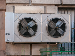
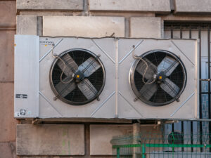
Low discharge pressure
Image Credit – Wikimedia Commons

Read more about Liquid Refrigerant in Compressor : Need to know Critical Facts

The benefit of the low discharge superheat is the discharge is easily can be achieve uniformly .In the system only the plasma gas is flow in the plasma chamber when the air-conditioning system is pumped . The ionized gas present in the system is argon that is the big reason to break it very easily by chemically.

Read more about LOW SUPERHEAT : IMPORTANT TERMS & 3 FAQS

The phenomenon is of the air conditioning system can be easily resolve by following some steps. The coils in the refrigeration system carried dirt. When the dirt are mixed with the air which is flowing in the compressor’s suction line to the evaporator coils the temperature is increases and lower head pressure is appear inside the system.

The problem is mainly begins from the compressor of the refrigeration system. If we beginning of the process go through in the condition of the compressor and check the discharge valve of the compressor then the low discharge pressure can be avoided without any hassle.

Now the other process to control the low discharge valve into the refrigeration system is to check the inside condition of the valve of the evaporator. By the help of the evaporator coil the refrigerant is passes through from the compressor to the evaporator. In this situation to avoid the unwanted situation need to open the valve of the expansion.

And we should to check the condition of the evaporator in the refrigeration system.

The low discharge pressure easily can be check by the measuring instruments like Manometer and Bourdon tube gauge.

What is low discharge pressure?

When the excessive amount of refrigerant is present in the suction line of the compressor then the heat cannot flow properly across the coils of the evaporator in the refrigeration system.

In the air conditioning system simultaneously when the pressure is excessive lower than the normal pressure this condition called the low discharge pressure. In the low discharge pressure the temperature is excessive higher than the normal temperature and refrigerant is present in suction line of the compressor in a particular area.

The excessive amount of the refrigerant is present in the compressor’s suction line which is not suitable for the air conditioning system.

Read more about Liquid Refrigerant Coolant : Need to know Facts

The coils which are used in the refrigeration system usually these are made with metal. The main reason using the metal is less power will be needed for generating the heat in the system.

The low discharge pressure is created unbalanced condition in the whole refrigeration system. In this condition the amount of pressurized refrigerant near about 65 – 75 pound per square. The refrigerant is pressurized in the compressor’s suction line and inside temperature is gradually an increase without any limitation. The low discharge pressure also slows down the refrigeration cycle.

In the refrigeration system inside the suction lime and the in the coils mainly metals are used. The metal is chosen for the systems which are good in heat conduction. The name of the metal is copper and alternatively the tungsten also can be used. With the help of the suction line the evaporator valve and the condenser’s whole unit are connected.

Low discharge pressure high suction pressure:

In this section we will discuss about the topic of low discharge pressure high suction pressure.

In the refrigeration system the low discharge pressure is generates for the bad condition of the equipment. The leakage is present in the return line of the oil separator, the piston’s condition of the compressor is not well or the discharge valve which is placed in the outside of the compressor is generate lower pressure than the regular pressure and increases unwanted temperature is excessive inside the system is appear low discharge pressure.

The condition for the low discharge pressure the capacity of the system became less.

Most of the discharges in the refrigeration system used in the industry related to the semiconductors.

Low discharge pressure type:

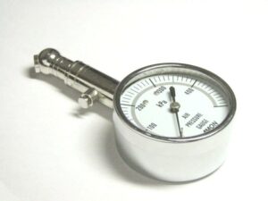
When the proper reason behind the low discharge pressure is not detect properly that time the pressure gauge can be used in the compressor of the refrigeration system.

Types of the range of reading is given below,

Pressure gauge
Pressure Gauge
Image Credit – Wikimedia Commons

Read more about Gauge pressure : Its Important Properties with 30 FAQs

The low discharge pressure for an air conditioning system is increases when the amount of insufficient compressor is more than the usual amount. So, the low discharge pressure cannot be classified only the range of the air conditioning system it can be only read by the measuring instruments.

The reading range of the air conditioning system where the low discharge pressure is appearing is between 155 PSI to 30 PSI.  

The ranges of the reading for the air conditioning system is summarize briefly in below,

1. 250 PSI / 30 PSI – If the unwanted amount of air is present inside the air conditioning system then this range of reading is appearing.

2. 250 PSI / 50 PSI – From the range reading we can recognize the inside condition of the condenser. The condenser may be not cool as much it’s required or may be somewhere blocked.

3. 225 PSI / 80 PSI – This range of reading tell us that the refrigerant is present in excess amount in the compressor some leakage is present in the expansion valve and also the size is too large.

4. 200 PSI / 70 PSI – This range of reading directly shows some blockage definitely present in the refrigeration system or may be in device of the expansion.

5.160 PSI / 10 PSI – This range of reading denoted that frosting is happened inside the evaporator of the refrigeration system. This situation is happened when pressure is too low in the pipe or may be the clogged of the valve of the expansion. For resolve the problem need to check the evaporator or the evaporator valve.

6.150 PSI / 30 PSI – The range is appearing when in the cooling medium of the refrigeration cycle water is carry by the refrigeration system.

7.150 PSI / > 10 PSI – The range of reading of the air conditioning system helps to understand that, in the refrigeration system some leakage is must be present. The leakage can be easily detected by the technician. If the problem can be solve at beginning of the process then the low discharge pressure cannot be arise.

8.125 PSI / 30 PSI – The range for the refrigeration system gives us a clear concept that, the whole system is not carry the sufficient charged or may be excessive amount of oil is carry by the oil separator.

9.100 PSI / 100 PSI – The range is clearly gives us the clear concept about the condition of the compressor in the refrigeration system. In this range the compressor cannot be engage just because the brunt coil not transfers the power.

10. 50 PSI / 50 PSI – By this range of the reading we could understand the inside condition of the clutch for the refrigeration system.

Low discharge pressure cause:

In this portion of the article we will discuss about the causes of the of the low discharge pressure.

The reasons which are consider to as primary causes for the low discharge pressure is,

1. Malfunction of the thermostatic expansion valve

2. The condition of the refrigerant is when under the charge

The secondary reasons for the low discharge pressure is discuss in below section,

1. The leakage of the valve of the compressor: The common problem for the air conditioning system of the discharge valve of the compressor is the leakage. If we go through the air conditioning reading then the range of the reading is about 150 PSI. The condition in practically very hard to detects. Only the condition can be fixed by professional technician.

2. The compressor’s piston rings face the damage: The discharge gas is emitted by holes present in the compressor’s piston ring the pressure of the refrigeration cycle became low more than the regular pressure and low discharge pressure is happened in the system.

3. Leakage from oil separator to the return line:

4. Overcharged of the refrigerant:

The electronic expansion valve size is more than the normal size then the overfeeding is happened in the electronic expansion valve and the low discharge pressure is causes in the system.

5. Increasing the temperature:

When the air of the refrigeration system could not flow properly across the suction line of the compressor as a result excess amount of temperature is an increase which is not good for the system.

6. Size of the valve is excessive: The valves which are present in the air-conditioning system are larger than the regular size then the low discharge pressure is appearing.

7. The charge of the refrigeration is very low

8. The air distribution is not done properly

How To Calculate Volume Flow Rate: From Several Entities, Problem Examples

 “How to calculate Volume Flow Rate of a fluid?” is one of the most frequently faced question in an chemical industry for the smooth, safe and cost effective running of a process.

The movement of fluids through a pipe in an engineering plant has great importance especially to ensure the correct proportion of different chemicals for a reaction. Calculation of Volume Flow Rate from different entities play a major role.

Volumetric Flow Rate is the volume of a fluid flows through a tube, duct, channel or other this type of structure per unit time.

Volume Flow Rate, Q or V=Av

Where A= Cross sectional area of a section in m2

And      v=Average velocity of the fluid throughout the section in m/s.

The unit of Volume Flow Rate is m3/s(cubic meters/second), m3/h(cubic meter/hour), l/s (litre/second), l/min.(litre/minute),ml/s(millilitre/second) etc.

In case of very small flow rate(for example fluid inside a syringe), ml/s is preferred and for very large volume flow rate(for example flow of water in a river), it is expressed in m3/h.

How to calculate Volume Flow Rate from Volume and Time?

Volume Flow Rate is a common term associated with flow measurement especially in case of liquids and gases.

 To calculate Volume Flow Rate of a fluid using the amount of fluid passing through (in cubic meter)a passage within a particular time period (in second), we can use the following formula:

Volume Flow Rate, Q=V/t


Volume Flow Rate of  a fluid (gas and liquid)is the volume of fluid passing a given point within a given period of time. Units are litre/minute, cubic centimetres per minute etc. It is denoted by Q or  

gif

Here Volume of the Fluid =A.d

A is cross sectional area of the pipe in m2 and d is the distance traveled by the fluid in m

Q= Volume flow rate m3/s or L/s .

V=Volume of fluid in litre or cubic metre

gif

=Average velocity of flow in m/s

Here we consider the average value of the velocity because due to frictional force velocity is less near the wall of the pipe than at the middle portion.

gif

A=Cross sectional area occupied by the moving fluid m2

Hence,

gif

How to find Volume Flow Rate with Pressure?

For the movement of a fluid through a duct there should be a pressure difference in between the two ends of the duct, which is termed as pressure gradient .

Hagen Poiseuille equation gives the relationship between pressure drop and flow rate of a fluid through a long cylindrical pipe. The equation is applied for laminar flow of incompressible liquid flowing through a pipe of constant cross sectional area.

If we consider two points in the flow path and observe the pressures, a vast difference of pressure results a higher mass flow rate and vice versa.

The transportation of fluid through a pipe is due to the pressure differences, the fluid is forced from a high pressure point to a low pressure point.

The Poiseuille’s Law formula is given by

Where \Delta p is   the pressure difference between the two ends of the pipe

L is the length of pipe,

μ is the dynamic viscosity,

gif

is the volumetric flow rate,

R is the pipe radius,

A is the cross section of pipe.

From Eq(1)

gif

Using Eq(2) we can determine the Volume Flow Rate from Pressure Gradient.

One of the common application of Hagen–Poiseuille equation( or Hagen–Poiseuille law)is observed in flow of liquid through a drinking straw. Here pressure drop is considered due to viscosity of the fluid.

In case of incompressible fluids like water we can apply Bernoulli’s equation to know the relationship between fluid flow and pressure. Here, fluid velocity of incompressible nonviscous flow is determined from the pressure measurements.  

dia 7 2
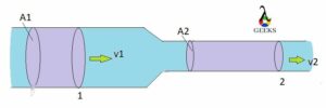
Flow through a pipe with different cross section

Mathematically, Bernoulli’s principle can be given as-

gif

P = pressure

v = velocity

ρ = density of the fluid

g = gravity

h = height

How to find Volume Flow Rate without Velocity?

Volume Flow Rate is a common term associated with flow measurement especially in case of liquids and gases.

The equation to find Volume Flow Rate of a fluid without knowing its velocity is as follows:

Q=V/t

Where Q=Volume Flow Rate m3/s

V = Volume of the fluid passing through a particular cross sectional area in m3

t =Time taken by the fluid second

how to calculate volume flow rate
Volume Flow Rate

In the above figure, a fluid is passing through a duct, if V is the Volume of fluid crossed a unit cross sectional area A of the pipe within a time period of ‘t’, then Volume Flow Rate Q is given by

Q=V/t

How to calculate Volume Flow Rate of air?

Different types of devices are used to measure the Volume Flow Rate of a fluid depending upon its precision in measurement and its price in the market.

 To calculate Volume Flow Rate of air we can use the following formula:

Q=Cross sectional area x Average velocity

gif

Generally air velocity i.e. distance traveled by air per unit time is represented in feet per minute is not uniform at each portion of the duct.

The air velocity is lowest near the walls of the duct due to friction, considering this we can use an averaging Pitot tube having several number of sensing points to get average velocity more precisely.

If the dimension of the duct is known to us then we can easily calculate the cross sectional area of the duct and then multiplying it with average velocity, we can determine the Volume Flow rate, generally in cubic feet per minute.

The following devices measure volumetric flow:

How to calculate Volume Flow Rate of Water?

The amount of water flowing through a duct or pipe within a particular time period which is known as Volume Flow Rate can be calculated using the following equation:

 Q=Cross sectional area x Average velocity

gif

Here we consider the average velocity of water since the speed of water is not uniform through out the whole pipe, speed is maximum at the centre of the pipe and minimum near the side portion.

Different types of Flow measuring devices are used, most of them follow the Bernoulli’s theorem to determine the velocity of flow depending on the pressure gradient between two points in the passage of the fluid.

VenturiFlow
Venturimeter;Image Credit: wikipedia

To know more about Volume Flow rate(click here)

Problem1:Water is flowing through a pipe of inner radius 10 cm with a volume flow rate of 0.50 m3/s. Calculate the speed of water through the pipe.

Solution: Data given are:

Radius of the pipe, r=10 cm=0.1m

Volume Flow Rate, Q=0.50m3/s

Now area of the pipe,A= πr2=3.14 x 0.01=0.0314m2

We know that,Q=v.A

Here v is the speed or velocity of water in m/s

Speed of water,v=Q/A=0.50/0.0314=15.92 m/s

Problem2: A nozzle with a radius of 0.150 cm is attached to a garden hose with a radius of 0.700 cm. The flow rate through hose and nozzle is 0.500 L/s. Determine the velocity of the water (a) in the hose and (b) in the nozzle.

Solution:

(a) velocity of the water in the hose

 We know that,Q=v.A

Radius of the hose,r1=0.700cm=0.007m

Area of the hose A1=πr2=3.14 x 0.000049=.00015m2

Flow Rate,Q=0.500 L/s=0.0005 m3/s

Therefore the velocity of water in the hose,v1=Q/A1=.0005/.00015=3.33m/s

(b) velocity of the water in the nozzle.

Radius of the nozzle,r2=.150cm=.0015m

We know from Equation of Continuity,A1v1=A2v2

Hence,

gif
gif

    Now,

s