Magnetic Flux and Electric Flux: A Comprehensive Guide for Physics Students

magnetic flux and electric

Magnetic flux and electric flux are fundamental concepts in the field of electromagnetism, with wide-ranging applications in various areas of physics and engineering. This comprehensive guide aims to provide a detailed and technical understanding of these crucial topics, equipping physics students with the necessary knowledge and tools to excel in their studies and research.

Understanding Magnetic Flux

Magnetic flux (Φ) is the measure of the total magnetic field (B) passing through a given area (A). It is represented by the formula Φ = B * A * cos(θ), where B is the magnetic field strength, A is the area, and θ is the angle between the magnetic field and the normal vector to the area.

Magnetic Flux Formula and Units

The formula for magnetic flux is:

Φ = B * A * cos(θ)

Where:
– Φ is the magnetic flux, measured in webers (Wb)
– B is the magnetic field strength, measured in teslas (T)
– A is the area, measured in square meters (m²)
– θ is the angle between the magnetic field and the normal vector to the area, measured in radians (rad)

The SI unit of magnetic flux is the weber (Wb), which is equivalent to one tesla square meter (T·m²).

Magnetic Flux Density

Magnetic flux density, measured in teslas (T), is used to quantify the strength of a magnetic field. It is essential in designing magnetic sensors, electromagnets, and MRI machines, where precise control and measurement of magnetic fields are necessary.

The formula for magnetic flux density is:

B = Φ / A

Where:
– B is the magnetic flux density, measured in teslas (T)
– Φ is the magnetic flux, measured in webers (Wb)
– A is the area, measured in square meters (m²)

Applications of Magnetic Flux

Magnetic flux plays a crucial role in various applications, including:

  1. Power generation: Magnetic flux is essential in the operation of generators, transformers, and electric motors, which are the backbone of power generation and distribution systems.
  2. Electromechanical motion: Magnetic flux is responsible for the force that drives the motion of electric motors, solenoids, and other electromechanical devices.
  3. Medical imaging: Magnetic flux is the foundation of magnetic resonance imaging (MRI) technology, which is widely used in medical diagnostics and research.
  4. Structural health monitoring: Magnetic flux can be used to detect and monitor structural defects and changes in materials, making it a valuable tool for non-destructive testing and evaluation.

Understanding Electric Flux

magnetic flux and electric flux

Electric flux is the measure of the total electric field (E) passing through a given area (A). It is represented by the formula ΦE = E * A, where E is the electric field strength and A is the area.

Electric Flux Formula and Units

The formula for electric flux is:

ΦE = E * A

Where:
– ΦE is the electric flux, measured in coulombs per square meter (C/m²)
– E is the electric field strength, measured in volts per meter (V/m)
– A is the area, measured in square meters (m²)

The SI unit of electric flux is the coulomb per square meter (C/m²).

Electric Flux Density

Electric flux density, also known as electric displacement, is the measure of the electric field (E) per unit area (D = εE). It is represented by the formula ΦE = D * A, where D is the electric flux density and A is the area.

The formula for electric flux density is:

D = ΦE / A

Where:
– D is the electric flux density, measured in coulombs per square meter (C/m²)
– ΦE is the electric flux, measured in coulombs per square meter (C/m²)
– A is the area, measured in square meters (m²)

The SI unit of electric flux density is the coulomb per square meter (C/m²).

Applications of Electric Flux

Electric flux is crucial for understanding the behavior of electric fields and their interactions with charges and matter. It has numerous applications, including:

  1. Capacitors: Electric flux is essential in the design and operation of capacitors, which are widely used in electronic circuits and power systems.
  2. Dielectrics: Electric flux is used to analyze the behavior of dielectric materials, which are important in the design of various electrical and electronic devices.
  3. Electromagnetic waves: Electric flux is a fundamental concept in the study of electromagnetic waves, such as those used in radio, television, and wireless communication.

Numerical Examples and Problems

To further solidify the understanding of magnetic flux and electric flux, let’s explore some numerical examples and problems.

Example 1: Calculating Magnetic Flux

Suppose a uniform magnetic field of 2 Tesla (T) is passing through a rectangular area of 0.5 m × 0.8 m, and the angle between the magnetic field and the normal vector to the area is 30 degrees.

Calculate the magnetic flux through the area.

Given:
– Magnetic field strength (B) = 2 T
– Area (A) = 0.5 m × 0.8 m = 0.4 m²
– Angle (θ) = 30 degrees

Using the formula for magnetic flux:
Φ = B * A * cos(θ)
Φ = 2 T * 0.4 m² * cos(30°)
Φ = 0.69 Wb

Therefore, the magnetic flux through the area is 0.69 Wb.

Example 2: Calculating Electric Flux

Consider a uniform electric field of 1000 V/m passing through a circular area with a radius of 0.2 m.

Calculate the electric flux through the area.

Given:
– Electric field strength (E) = 1000 V/m
– Area (A) = π * (0.2 m)² = 0.126 m²

Using the formula for electric flux:
ΦE = E * A
ΦE = 1000 V/m * 0.126 m²
ΦE = 126 C/m²

Therefore, the electric flux through the area is 126 C/m².

Problem 1: Magnetic Flux Density

A solenoid with 500 turns and a cross-sectional area of 0.02 m² carries a current of 5 A. Calculate the magnetic flux density inside the solenoid.

Given:
– Number of turns (N) = 500
– Cross-sectional area (A) = 0.02 m²
– Current (I) = 5 A

Using the formula for magnetic flux density:
B = μ0 * N * I / A
B = 4π × 10^-7 H/m * 500 * 5 A / 0.02 m²
B = 0.157 T

Therefore, the magnetic flux density inside the solenoid is 0.157 T.

Problem 2: Electric Flux Density

A parallel-plate capacitor has a plate area of 0.1 m² and a separation distance of 2 mm. If the capacitor is charged with a total charge of 10 μC, calculate the electric flux density between the plates.

Given:
– Plate area (A) = 0.1 m²
– Separation distance (d) = 2 mm = 0.002 m
– Total charge (Q) = 10 μC = 10 × 10^-6 C

Using the formula for electric flux density:
D = Q / A
D = (10 × 10^-6 C) / (0.1 m²)
D = 0.0001 C/m²

Therefore, the electric flux density between the plates of the capacitor is 0.0001 C/m².

Conclusion

Magnetic flux and electric flux are fundamental concepts in the field of electromagnetism, with wide-ranging applications in various areas of physics and engineering. This comprehensive guide has provided a detailed and technical understanding of these crucial topics, equipping physics students with the necessary knowledge and tools to excel in their studies and research.


Reference:

  1. Magnetic Flux – an overview | ScienceDirect Topics
  2. Fundamentals of Magnetic Flux and Reluctance – Study for FE
  3. Electric Flux vs Magnetic Flux Units – Physics Stack Exchange
  4. Applications of Magnetic Flux – GeeksforGeeks
  5. Search Coil Experiment (measure magnetic field strength) – YouTube

Magnetic Flux and Area: A Comprehensive Guide for Physics Students

magnetic flux and area

Magnetic flux (Φ) is a fundamental concept in electromagnetism that quantifies the total magnetic field passing through a specified surface. It is a crucial parameter in various fields, including physics, engineering, and materials science. This comprehensive guide will delve into the intricacies of magnetic flux and its relationship with surface area, providing a detailed exploration for physics students.

Understanding Magnetic Flux

Magnetic flux is a measure of the total magnetic field that penetrates a specified closed surface. It is quantified by counting the magnetic field lines that intersect the surface. The SI unit of magnetic flux is the Weber (Wb), named after the German physicist Wilhelm Eduard Weber.

The formula for magnetic flux is given by:

ϕ_B = B ⋅ A = B A cos(θ)

Where:
– ϕ_B is the magnetic flux (in Webers)
– B is the magnetic field (in Teslas)
– A is the surface area (in square meters)
– θ is the angle between the magnetic field and the normal to the surface (in radians)

This equation demonstrates that the magnetic flux depends on the strength of the magnetic field, the area of the surface, and the angle at which the field lines pass through the surface. Magnetic flux is a scalar quantity, meaning its magnitude depends on these factors, but it does not have a specific direction.

Magnetic Flux Density

magnetic flux and area

Closely related to magnetic flux is the concept of magnetic flux density, also known as magnetic induction or magnetic field strength. Magnetic flux density (B) is a measure of the concentration of magnetic field lines in a given area. It is defined as the number of magnetic field lines per unit area and is measured in Tesla (T).

The formula for magnetic flux density is:

B = ϕ_B / A

Where:
– B is the magnetic flux density (in Teslas)
– ϕ_B is the magnetic flux (in Webers)
– A is the surface area (in square meters)

Magnetic flux density is a vector quantity, meaning it has both magnitude and direction. It represents the strength and direction of the magnetic field at a specific point in space.

Measuring Magnetic Flux

The measurement of magnetic flux and magnetic flux density is crucial in various fields, including physics, engineering, and materials science. A device commonly used to measure magnetic flux is a magnetometer.

A magnetometer works by measuring the voltage induced in a coil by the magnetic field. The voltage is proportional to the rate of change of the magnetic flux with time, as described by Faraday’s law of electromagnetic induction:

ε = -dϕ_B/dt

Where:
– ε is the induced electromotive force (EMF) in the coil (in Volts)
– dϕ_B/dt is the rate of change of the magnetic flux with time (in Webers per second)

By measuring the induced voltage in the coil, the magnetometer can determine the magnitude and direction of the magnetic flux, which is then used to calculate the magnetic flux density.

Magnetic Flux Indicators and QQIs

In the context of magnetic particle testing, magnetic flux indicators and Quantitative Quality Indicators (QQIs) are used to verify the direction and strength of the magnetic field.

Magnetic Flux Indicators

Magnetic flux indicator strips are used to visualize the direction of the magnetic field. These strips are positioned so that their long dimension is perpendicular to the applied magnetic field. When the magnetic field is energized and magnetic particles (wet suspension or dry powder) are applied, the indications will be strongest and most well-defined when the strip is perpendicular to the magnetic flux. No indications will form if the strip is aligned parallel to the magnetic flux.

Quantitative Quality Indicators (QQIs)

QQIs are artificial flaw notched shims that are attached to example parts to demonstrate both the field strength and direction within a part. They are useful for setting up the magnetization parameters for part-specific techniques and can be used to create an example part for the daily system performance check of the magnetizing equipment.

By using magnetic flux indicators and QQIs, technicians can ensure that the magnetic field is properly oriented and of sufficient strength for effective magnetic particle testing.

Practical Applications of Magnetic Flux and Flux Density

The concepts of magnetic flux and flux density have numerous practical applications in various fields:

  1. Electrical Machines: In electric motors and generators, the magnetic flux and flux density are crucial parameters that determine the efficiency, torque, and power output of the machine.

  2. Transformers: The magnetic flux in the core of a transformer determines the voltage transformation ratio and the power transfer capability of the device.

  3. Magnetic Resonance Imaging (MRI): MRI machines rely on the precise control and measurement of magnetic flux density to generate high-quality images of the human body.

  4. Magnetic Levitation: Magnetic levitation trains and other levitation systems utilize the precise control of magnetic flux to achieve frictionless, high-speed transportation.

  5. Magnetic Particle Testing: As mentioned earlier, magnetic flux indicators and QQIs are used in magnetic particle testing to ensure the proper orientation and strength of the magnetic field for non-destructive evaluation of materials.

  6. Magnetic Data Storage: The storage and retrieval of data in magnetic media, such as hard drives and magnetic tapes, rely on the precise control and measurement of magnetic flux.

  7. Magnetic Shielding: Understanding magnetic flux and flux density is crucial for designing effective magnetic shielding systems to protect sensitive electronic equipment from external magnetic fields.

Numerical Examples and Problems

To further solidify your understanding of magnetic flux and its relationship with surface area, let’s explore some numerical examples and problems:

  1. Example 1: A uniform magnetic field of 0.5 Tesla is applied perpendicular to a rectangular surface with dimensions of 10 cm × 15 cm. Calculate the magnetic flux through the surface.

Given:
– Magnetic field (B) = 0.5 Tesla
– Surface area (A) = 10 cm × 15 cm = 0.15 m²
– Angle (θ) = 0° (perpendicular to the surface)

Magnetic flux (ϕ_B) = B × A × cos(θ)
ϕ_B = 0.5 T × 0.15 m² × cos(0°) = 0.075 Wb

  1. Problem 1: A circular coil with a radius of 20 cm is placed in a uniform magnetic field of 1 Tesla. Calculate the magnetic flux through the coil if the angle between the normal to the coil and the magnetic field is 30°.

Given:
– Magnetic field (B) = 1 Tesla
– Coil radius (r) = 20 cm = 0.2 m
– Angle (θ) = 30°

Surface area (A) = π × r² = π × (0.2 m)² = 0.1256 m²
Magnetic flux (ϕ_B) = B × A × cos(θ)
ϕ_B = 1 T × 0.1256 m² × cos(30°) = 0.1088 Wb

  1. Problem 2: A square coil with a side length of 50 cm is placed in a uniform magnetic field of 0.8 Tesla. Calculate the magnetic flux through the coil if the angle between the normal to the coil and the magnetic field is 45°.

Given:
– Magnetic field (B) = 0.8 Tesla
– Coil side length (s) = 50 cm = 0.5 m
– Angle (θ) = 45°

Surface area (A) = s² = (0.5 m)² = 0.25 m²
Magnetic flux (ϕ_B) = B × A × cos(θ)
ϕ_B = 0.8 T × 0.25 m² × cos(45°) = 0.1414 Wb

These examples and problems demonstrate the application of the magnetic flux formula and the importance of considering the angle between the magnetic field and the surface area. By working through these exercises, you can deepen your understanding of the concepts and their practical implications.

Conclusion

Magnetic flux and magnetic flux density are fundamental concepts in the study of electromagnetism. Understanding the relationship between magnetic flux, surface area, and the angle of the magnetic field is crucial for various applications in physics, engineering, and materials science.

This comprehensive guide has provided a detailed exploration of magnetic flux, including the formula, the concept of magnetic flux density, and the measurement of magnetic flux using magnetometers. Additionally, the practical applications of these concepts, as well as numerical examples and problems, have been discussed to enhance your understanding and problem-solving skills.

By mastering the intricacies of magnetic flux and area, you will be better equipped to tackle complex problems, design efficient electrical machines and devices, and contribute to the advancement of various fields that rely on the principles of electromagnetism.

References

  1. Wired. (2014). How to Measure a Magnetic Field. [online] Available at: https://www.wired.com/2014/01/measure-magnetic-field/ [Accessed 15 May 2023].
  2. e-magnetica.pl. (n.d.). Magnetic Flux Density. [online] Available at: https://www.e-magnetica.pl/doku.php/magnetic_flux_density [Accessed 15 May 2023].
  3. GeeksforGeeks. (n.d.). Magnetic Flux. [online] Available at: https://www.geeksforgeeks.org/magnetic-flux/ [Accessed 15 May 2023].
  4. Magnaflux. (n.d.). Flux Indicators and QQIs. [online] Available at: https://magnaflux.com/Magnaflux/Resources/Blog/Flux-Indicators-and-QQIs [Accessed 15 May 2023].
  5. YouTube. (2018). Magnetic Flux Density and Magnetic Flux. [online] Available at: https://www.youtube.com/watch?v=N4H1X4i2OZ4 [Accessed 15 May 2023].

Mastering Dynamic Equilibrium Conditions: A Comprehensive Guide

dynamic equilibrium conditions

Dynamic equilibrium is a fundamental concept in chemistry and physics, describing a state where the rate of the forward reaction equals the rate of the backward reaction, resulting in constant concentrations of reactants and products. This intricate balance is governed by a set of principles and mathematical relationships that are crucial for understanding and predicting the behavior of chemical systems. In this comprehensive guide, we will delve into the technical details, formulas, and practical applications of dynamic equilibrium conditions.

Understanding the Principles of Dynamic Equilibrium

At the heart of dynamic equilibrium lies the principle of reversibility. In a reversible reaction, the forward and backward reactions occur simultaneously, with the rates of these processes being equal at equilibrium. This can be represented by the general equation:

A + B ⇌ C + D

where the forward reaction rate is equal to the backward reaction rate, resulting in a constant composition of the system.

The key properties of dynamic equilibrium include:

  1. Constant Concentrations: The concentrations of reactants and products remain constant over time, as the forward and backward reaction rates are equal.
  2. Constant Measurable Properties: Properties such as concentration, density, color, and pressure remain constant at a given temperature.
  3. Reversibility: The reaction is reversible, with the forward and backward reactions occurring simultaneously.
  4. Equilibrium Constant (Keq): The equilibrium constant, Keq, is a measure of the equilibrium position and is calculated as the ratio of the concentrations of products to reactants, raised to the power of their stoichiometric coefficients.

Equilibrium Constant (Keq) and Its Significance

dynamic equilibrium conditions

The equilibrium constant, Keq, is a crucial parameter in understanding and predicting the behavior of a dynamic equilibrium system. It is defined as the ratio of the concentrations of the products raised to their stoichiometric coefficients, divided by the concentrations of the reactants raised to their stoichiometric coefficients.

For the general reaction:

aA + bB ⇌ cC + dD

The equilibrium constant, Keq, is calculated as:

Keq = [C]^c × [D]^d / ([A]^a × [B]^b)

where [A], [B], [C], and [D] represent the equilibrium concentrations of the respective species, and a, b, c, and d are their stoichiometric coefficients.

The value of Keq provides valuable insights into the equilibrium position of the reaction:

  • A large Keq value (>> 1) indicates that the reaction favors the formation of products.
  • A small Keq value (< 1) indicates that the reaction favors the formation of reactants.
  • A Keq value of 1 indicates that the reaction is at equilibrium, with equal amounts of reactants and products.

The equilibrium constant is a powerful tool for predicting the direction of a reaction and the relative concentrations of reactants and products at equilibrium.

Factors Affecting Dynamic Equilibrium

The position of a dynamic equilibrium can be influenced by various factors, including temperature, pressure, and the addition or removal of reactants or products. These factors can be understood and predicted using the principles of Le Chatelier’s Principle.

  1. Temperature: An increase in temperature will shift the equilibrium in the direction that absorbs heat (endothermic reaction), while a decrease in temperature will shift the equilibrium in the direction that releases heat (exothermic reaction).

  2. Pressure: An increase in pressure will shift the equilibrium in the direction that reduces the total number of moles of gas, while a decrease in pressure will shift the equilibrium in the direction that increases the total number of moles of gas.

  3. Addition or Removal of Reactants or Products: Adding a reactant or removing a product will shift the equilibrium in the direction that counteracts the change, while adding a product or removing a reactant will shift the equilibrium in the direction that counteracts the change.

These principles can be used to predict the direction of the shift in the equilibrium position and the resulting changes in the concentrations of reactants and products.

Practical Applications of Dynamic Equilibrium

Dynamic equilibrium conditions have numerous practical applications in various fields, including:

  1. Chemical Processes: Understanding dynamic equilibrium is crucial in the design and optimization of chemical processes, such as the Haber process for the production of ammonia, the Contact process for the production of sulfuric acid, and the Solvay process for the production of sodium carbonate.

  2. Biological Systems: Dynamic equilibrium plays a vital role in biological systems, such as the maintenance of pH in the human body, the transport of molecules across cell membranes, and the regulation of enzyme-catalyzed reactions.

  3. Environmental Chemistry: Dynamic equilibrium principles are used to understand and predict the behavior of pollutants in the environment, such as the distribution of heavy metals in soil and water, the formation of acid rain, and the fate of organic compounds in aquatic ecosystems.

  4. Materials Science: Dynamic equilibrium concepts are applied in the study of phase transitions, the formation of solid solutions, and the understanding of defects in crystalline materials.

  5. Atmospheric Chemistry: Dynamic equilibrium is crucial in understanding the composition of the Earth’s atmosphere, including the formation and dissociation of ozone, the transport of greenhouse gases, and the dynamics of atmospheric reactions.

By understanding the principles of dynamic equilibrium, scientists and engineers can design more efficient and sustainable chemical processes, predict the behavior of complex systems, and develop innovative solutions to pressing environmental and technological challenges.

Numerical Examples and Problem-Solving Strategies

To solidify your understanding of dynamic equilibrium conditions, let’s explore some numerical examples and problem-solving strategies.

Example 1: Calculating the Equilibrium Constant (Keq)

Consider the following reversible reaction:

2NO(g) + Cl2(g) ⇌ 2NOCl(g)

At equilibrium, the concentrations of the reactants and products are:
[NO] = 0.10 M, [Cl2] = 0.050 M, and [NOCl] = 0.20 M.

Calculate the equilibrium constant, Keq, for this reaction.

Solution:
The equilibrium constant, Keq, is calculated as:

Keq = [NOCl]^2 / ([NO]^2 × [Cl2])
Keq = (0.20 M)^2 / ((0.10 M)^2 × 0.050 M)
Keq = 0.04 / 0.0005
Keq = 80

Therefore, the equilibrium constant, Keq, for this reaction is 80.

Example 2: Predicting the Direction of Reaction Shift

Consider the following reversible reaction:

N2(g) + 3H2(g) ⇌ 2NH3(g)

The reaction is initially at equilibrium, with the following concentrations:
[N2] = 0.20 M, [H2] = 0.60 M, and [NH3] = 0.10 M.

If the pressure is increased, predict the direction of the shift in the equilibrium position.

Solution:
To predict the direction of the shift, we can use Le Chatelier’s Principle.

The reaction has the following balanced equation:
N2(g) + 3H2(g) ⇌ 2NH3(g)

Increasing the pressure will shift the equilibrium in the direction that reduces the total number of moles of gas. In this case, the forward reaction (formation of NH3) reduces the total number of moles of gas, as 4 moles of reactants (N2 and 3H2) are converted to 2 moles of product (2NH3).

Therefore, increasing the pressure will shift the equilibrium in the forward direction, towards the formation of more NH3.

Example 3: Solving a Dynamic Equilibrium Problem

A mixture of H2(g) and I2(g) is allowed to reach equilibrium at a certain temperature, and the equilibrium concentrations are found to be:
[H2] = 0.10 M, [I2] = 0.10 M, and [HI] = 0.80 M.

Calculate the value of the equilibrium constant, Keq, for the reaction:
H2(g) + I2(g) ⇌ 2HI(g)

Solution:
The equilibrium constant, Keq, is calculated as:

Keq = [HI]^2 / ([H2] × [I2])

Substituting the given values:
Keq = (0.80 M)^2 / (0.10 M × 0.10 M)
Keq = 0.64 / 0.01
Keq = 64

Therefore, the equilibrium constant, Keq, for the given reaction is 64.

These examples demonstrate the application of the principles of dynamic equilibrium, including the calculation of the equilibrium constant and the prediction of the direction of reaction shifts. By mastering these concepts and problem-solving strategies, you can develop a deep understanding of dynamic equilibrium conditions and their practical implications.

Conclusion

Dynamic equilibrium is a fundamental concept in chemistry and physics, describing a state where the forward and backward reaction rates are equal, resulting in constant concentrations of reactants and products. Understanding the principles of dynamic equilibrium, the significance of the equilibrium constant (Keq), and the factors that affect the equilibrium position is crucial for analyzing and predicting the behavior of chemical systems.

By exploring the technical details, formulas, and practical applications of dynamic equilibrium conditions, you can develop a comprehensive understanding of this important topic. The examples and problem-solving strategies provided in this guide will help you apply the principles of dynamic equilibrium to a wide range of scenarios, from chemical processes to biological systems and environmental chemistry.

Mastering dynamic equilibrium conditions is an essential step in becoming a proficient physicist or chemist, as it underpins the understanding of many complex phenomena in the natural world. By continuing to explore and deepen your knowledge in this area, you will be well-equipped to tackle challenging problems, design innovative solutions, and contribute to the advancement of scientific knowledge.

References

  1. A framework for quantifying deviations from dynamic equilibrium theory. (2021). Retrieved from https://www.researchgate.net/publication/355159538_A_framework_for_quantifying_deviations_from_dynamic_equilibrium_theory
  2. Dynamic Equilibrium. (2013). Retrieved from https://www.unite.it/UniTE/Engine/RAServeFile.php/f/File_Prof/CHIARINI_2014/Equilibrio_Chimico.pdf
  3. The Idea of Dynamic Chemical Equilibrium. (2022). Retrieved from https://chem.libretexts.org/Bookshelves/Introductory_Chemistry/Introductory_Chemistry/15:_Chemical_Equilibrium/15.03:_The_Idea_of_Dynamic_Chemical_Equilibrium
  4. Identify the common property for a chemical reaction at dynamic equilibrium. (2022). Retrieved from https://byjus.com/question-answer/identify-the-common-property-for-a-chemical-reaction-at-dynamic-equilibrium/
  5. Dynamic Equilibrium. (n.d.). Retrieved from https://www.studysmarter.co.uk/explanations/chemistry/physical-chemistry/dynamic-equilibrium/

The State of Dynamic Equilibrium: A Comprehensive Guide for Physics Students

state of dynamic equilibrium

The state of dynamic equilibrium is a fundamental concept in physical chemistry, which describes a reversible reaction where the rate of the forward reaction equals the rate of the backward reaction, and the concentrations of reactants and products remain constant over time. This state is characterized by equal reaction rates and constant concentrations, making it a crucial principle for understanding many industrial processes and chemical reactions.

Understanding the Principles of Dynamic Equilibrium

At the heart of dynamic equilibrium lies the principle of equal reaction rates. In a reversible reaction, the forward and backward reactions occur simultaneously, and at dynamic equilibrium, the rate of the forward reaction is exactly equal to the rate of the backward reaction. This can be expressed mathematically as:

$r_f = r_b$

where $r_f$ is the rate of the forward reaction and $r_b$ is the rate of the backward reaction.

The second key property of dynamic equilibrium is the constancy of reactant and product concentrations. Despite the ongoing forward and backward reactions, the concentrations of the reactants and products remain constant over time. This can be represented by the following equation:

$\frac{d[A]}{dt} = \frac{d[B]}{dt} = \frac{d[C]}{dt} = \frac{d[D]}{dt} = 0$

where $[A]$, $[B]$, $[C]$, and $[D]$ are the concentrations of the reactants and products, and the derivatives with respect to time are equal to zero, indicating no change in concentration.

It is important to note that dynamic equilibrium does not necessarily mean that the concentrations of reactants and products are equal. In the reaction $\text{A} + \text{B} \rightleftharpoons \text{C} + \text{D}$, the concentrations of $\text{A}$, $\text{B}$, $\text{C}$, and $\text{D}$ may be different at equilibrium, but they will remain constant over time.

Factors Affecting Dynamic Equilibrium

state of dynamic equilibrium

The state of dynamic equilibrium can be influenced by various factors, including temperature, pressure, and the presence of catalysts. These factors can affect the rates of the forward and backward reactions, ultimately influencing the equilibrium concentrations of the reactants and products.

Temperature

Temperature is a crucial factor in dynamic equilibrium. According to the Arrhenius equation, the rate constant of a reaction is exponentially dependent on temperature. As the temperature increases, the rate constants of both the forward and backward reactions increase, but the ratio of the rate constants, known as the equilibrium constant ($K_c$), remains constant. This relationship is expressed by the van ‘t Hoff equation:

$\frac{d\ln K_c}{dT} = \frac{\Delta H^\circ}{RT^2}$

where $\Delta H^\circ$ is the standard enthalpy change of the reaction, $R$ is the universal gas constant, and $T$ is the absolute temperature.

Pressure

Pressure can also affect the state of dynamic equilibrium, particularly in reactions involving changes in the number of moles of gaseous reactants and products. According to Le Chatelier’s principle, if a system at equilibrium is subjected to a change in pressure, the system will shift to counteract the change and establish a new equilibrium state. For example, in the reaction $\text{N}_2 + 3\text{H}_2 \rightleftharpoons 2\text{NH}_3$, an increase in pressure will favor the forward reaction, which has a smaller number of moles of gaseous reactants, to produce more ammonia and reach a new equilibrium.

Catalysts

The presence of a catalyst can also influence the state of dynamic equilibrium. Catalysts work by providing an alternative reaction pathway with a lower activation energy, which increases the rate of both the forward and backward reactions. However, the equilibrium constant ($K_c$) remains unchanged, as the catalyst affects the rates of both the forward and backward reactions equally.

Quantifying Deviations from Dynamic Equilibrium

While the principles of dynamic equilibrium provide a useful framework for understanding many chemical systems, real-world systems may not always adhere strictly to these principles. Researchers have developed statistical tools to quantify deviations from dynamic equilibrium theory and gain insights into the underlying mechanisms driving the system away from equilibrium.

One such tool is the framework for quantifying deviations from dynamic equilibrium theory, proposed by Grilli et al. (2021). This framework involves testing the assumptions of dynamic equilibrium, such as species independence and constancy of colonization and extinction rates, using statistical methods. By identifying when a system is not in dynamic equilibrium, this framework can provide valuable information about the factors influencing the system’s behavior.

Practical Applications of Dynamic Equilibrium

The concept of dynamic equilibrium has numerous practical applications in various fields, particularly in industrial chemistry and chemical engineering.

The Haber Process

One prominent example is the Haber process, which is used to produce ammonia (NH3) from nitrogen (N2) and hydrogen (H2). The reaction is reversible, and at dynamic equilibrium, the rate of the forward reaction (N2 + 3H2 → 2NH3) is equal to the rate of the backward reaction (2NH3 → N2 + 3H2), with the concentrations of the reactants and products remaining constant.

Acid-Base Equilibria

Dynamic equilibrium is also observed in acid-base reactions, where the forward and backward reactions occur simultaneously. For example, in the dissociation of acetic acid (CH3COOH) in water, the forward reaction (CH3COOH → CH3COO- + H+) and the backward reaction (CH3COO- + H+ → CH3COOH) reach a dynamic equilibrium, with the concentrations of the reactants and products remaining constant.

Solubility Equilibria

Another application of dynamic equilibrium is in solubility equilibria, where a solid solute is in equilibrium with its dissolved ions in a solution. For example, in the dissolution of silver chloride (AgCl), the forward reaction (AgCl(s) → Ag+ + Cl-) and the backward reaction (Ag+ + Cl- → AgCl(s)) reach a dynamic equilibrium, with the concentrations of the dissolved ions remaining constant.

Conclusion

The state of dynamic equilibrium is a fundamental concept in physical chemistry, characterized by equal reaction rates and constant concentrations of reactants and products. Understanding the principles of dynamic equilibrium, the factors that influence it, and the tools used to quantify deviations from the theory is crucial for physics students and researchers working in various fields, from industrial chemistry to chemical engineering. By mastering the intricacies of dynamic equilibrium, students can gain a deeper understanding of the complex chemical systems that govern our world.

References:

  1. Thermodynamic equilibrium – Wikipedia. (n.d.). Retrieved June 23, 2024, from https://en.wikipedia.org/wiki/Thermodynamic_equilibrium
  2. Identify the common property for a chemical reaction at dynamic equilibrium. (n.d.). Retrieved June 23, 2024, from https://byjus.com/question-answer/identify-the-common-property-for-a-chemical-reaction-at-dynamic-equilibrium/
  3. A framework for quantifying deviations from dynamic equilibrium theory. (2021, October 13). Retrieved June 23, 2024, from https://www.researchgate.net/publication/355159538_A_framework_for_quantifying_deviations_from_dynamic_equilibrium_theory
  4. 15.3: The Idea of Dynamic Chemical Equilibrium. (n.d.). Retrieved June 23, 2024, from https://chem.libretexts.org/Bookshelves/Introductory_Chemistry/Introductory_Chemistry/15:_Chemical_Equilibrium/15.03:_The_Idea_of_Dynamic_Chemical_Equilibrium
  5. Dynamic Equilibrium. (n.d.). Retrieved June 23, 2024, from https://www.studysmarter.co.uk/explanations/chemistry/physical-chemistry/dynamic-equilibrium/

Is Thermal Equilibrium a System?

is thermal equilibrium a system

Thermal equilibrium is not a system itself, but rather a state that a system can be in. In this state, two objects or systems in physical contact with each other do not exchange heat energy, meaning there is no net transfer of kinetic energy between them. This occurs when the objects or systems have the same temperature.

Understanding Thermal Equilibrium

Thermal equilibrium can be quantified through the use of the Helmholtz free energy equation, which is given by:

F = U – TS

Where:
– F is the Helmholtz free energy
– U is the internal energy
– T is the temperature
– S is the entropy of the system

This equation allows for the calculation of the maximum reversible work that can be done by a system at constant temperature and volume.

In the context of thermal equilibrium, if two systems are in contact and not exchanging heat energy, their temperatures must be the same, and their Helmholtz free energies must also be the same. This is because the Helmholtz free energy is a function of temperature and entropy, and in thermal equilibrium, the temperatures and entropies of the two systems are equal.

Examples of Thermal Equilibrium

is thermal equilibrium a system

Consider two identical boxes of matter, A and B, that are in thermal contact but initially at different temperatures. As they exchange heat energy, their temperatures will gradually equalize, and when they reach thermal equilibrium, their Helmholtz free energies will also be equal.

Numerical Problem

Calculate the Helmholtz free energy of a system with an internal energy of 50,000 joules, a temperature of 370 kelvins, and an entropy of 10 joules/kelvin.

Given:
– Internal energy (U) = 50,000 joules
– Temperature (T) = 370 kelvins
– Entropy (S) = 10 joules/kelvin

Using the Helmholtz free energy equation:
F = U – TS
F = 50,000 – (370 × 10)
F = 50,000 – 3,700
F = 46,300 joules

Therefore, the Helmholtz free energy of the system is 46,300 joules.

Importance of Thermal Equilibrium

Thermal equilibrium is a dynamic process, meaning that it is constantly being maintained through the exchange of heat energy between systems. Once thermal equilibrium is reached, it will persist as long as the systems remain in contact and no external influences cause a change in their temperatures.

Understanding thermal equilibrium is crucial in various fields, such as thermodynamics, heat transfer, and energy systems, as it helps in the analysis and optimization of these systems.

Conclusion

In summary, thermal equilibrium is not a system itself, but a state that a system can be in. It is characterized by the absence of heat exchange between systems in contact, and can be quantified through the use of the Helmholtz free energy equation. Thermal equilibrium is a dynamic process that is constantly being maintained through the exchange of heat energy between systems.

Reference:
1. Thermal Equilibrium Definition, Equation & Examples – Lesson
2. HW3 Flashcards – Quizlet
3. Thermodynamic Equilibrium – an overview | ScienceDirect Topics

Mastering Relative Angular Velocity: A Comprehensive Guide

relative angular velocity

Relative angular velocity is a fundamental concept in physics that describes the rate of rotation of one object with respect to another. This measure is crucial in understanding the dynamics of rotating systems, from the Earth’s rotation to the motion of car wheels and spinning tops. In this comprehensive guide, we will delve into the intricacies of relative angular velocity, providing a wealth of technical details, formulas, examples, and numerical problems to help you gain a deep understanding of this essential topic.

Understanding Relative Angular Velocity

Relative angular velocity is the rate of change of the angular position of one object with respect to another. It is typically measured in radians per second (rad/s) or degrees per second (deg/s). This measure is crucial in understanding the dynamics of rotating systems, as it allows us to quantify the relative motion between two objects.

The formula for relative angular velocity is:

$\omega_{rel} = \omega_1 – \omega_2$

Where:
– $\omega_{rel}$ is the relative angular velocity
– $\omega_1$ is the angular velocity of the first object
– $\omega_2$ is the angular velocity of the second object

It’s important to note that the relative angular velocity can be positive or negative, depending on the direction of rotation of the two objects.

Measuring Relative Angular Velocity

relative angular velocity

Measuring relative angular velocity requires the use of specialized sensors and instruments. Here are some common methods and their associated data points:

Angular Velocity of the Earth

  • The Earth rotates on its axis once every 24 hours, which means its angular velocity is approximately 0.0000727 rad/s.
  • The angular velocity of the Earth relative to the Sun is about 0.0000102 rad/s, as the Earth orbits the Sun once every 365.25 days.

Angular Velocity of a Car Wheel

  • The angular velocity of a car wheel depends on the speed of the car and the radius of the wheel.
  • For example, if a car is moving at a speed of 60 km/h (16.67 m/s) and the radius of the wheel is 0.3 m, the angular velocity of the wheel is approximately 34.6 rad/s.

Angular Velocity of a Spinning Top

  • The angular velocity of a spinning top can be measured using a high-speed camera and image processing software.
  • For example, a top spinning at a rate of 10 revolutions per second has an angular velocity of approximately 628 rad/s.

Angular Velocity of a Gyroscope

  • The angular velocity of a gyroscope can be measured using a variety of sensors, such as optical encoders, magnetometers, or accelerometers.
  • For example, a gyroscope with a sensitivity of 1 degree per second (0.0175 rad/s) can measure angular velocities up to several hundred rad/s.

Calculating Relative Angular Velocity

To calculate the relative angular velocity between two objects, you can use the formula:

$\omega_{rel} = \omega_1 – \omega_2$

Here are some examples:

  1. Example 1: A car is moving at a speed of 60 km/h (16.67 m/s) and the radius of the wheel is 0.3 m. The angular velocity of the wheel is 34.6 rad/s. The car is driving on a road that is rotating at an angular velocity of 0.0001 rad/s. Calculate the relative angular velocity between the wheel and the road.

Solution:
– Angular velocity of the wheel: $\omega_1 = 34.6$ rad/s
– Angular velocity of the road: $\omega_2 = 0.0001$ rad/s
– Relative angular velocity: $\omega_{rel} = \omega_1 – \omega_2 = 34.6 – 0.0001 = 34.5999$ rad/s

  1. Example 2: A gyroscope has a sensitivity of 1 degree per second (0.0175 rad/s) and can measure angular velocities up to several hundred rad/s. If the gyroscope is measuring an angular velocity of 150 rad/s, what is the relative angular velocity between the gyroscope and the object it is measuring?

Solution:
– Angular velocity of the gyroscope: $\omega_1 = 150$ rad/s
– Angular velocity of the object: $\omega_2 = 0$ rad/s (assuming the object is stationary)
– Relative angular velocity: $\omega_{rel} = \omega_1 – \omega_2 = 150$ rad/s

  1. Example 3: The Earth rotates on its axis once every 24 hours, and it orbits the Sun once every 365.25 days. Calculate the relative angular velocity between the Earth’s rotation and its orbit around the Sun.

Solution:
– Angular velocity of the Earth’s rotation: $\omega_1 = 0.0000727$ rad/s
– Angular velocity of the Earth’s orbit around the Sun: $\omega_2 = 0.0000102$ rad/s
– Relative angular velocity: $\omega_{rel} = \omega_1 – \omega_2 = 0.0000727 – 0.0000102 = 0.0000625$ rad/s

Relative Angular Velocity in Practical Applications

Relative angular velocity has numerous practical applications in various fields, including:

  1. Robotics and Automation: Relative angular velocity is crucial in the control and navigation of robotic systems, allowing for precise control of rotational motion.
  2. Aerospace Engineering: Relative angular velocity is essential in the design and control of aircraft, satellites, and spacecraft, where the accurate measurement of rotational motion is crucial for stability and navigation.
  3. Mechanical Engineering: Relative angular velocity is used in the analysis and design of rotating machinery, such as gears, bearings, and turbines, to ensure efficient and reliable operation.
  4. Biomechanics: Relative angular velocity is used to study the rotational motion of the human body, such as the movement of joints and limbs, which is essential for understanding and improving human performance and rehabilitation.
  5. Geophysics: Relative angular velocity is used to study the Earth’s rotation and its interactions with other celestial bodies, which is crucial for understanding phenomena such as tides, precession, and nutation.

Numerical Problems and Exercises

To further solidify your understanding of relative angular velocity, here are some numerical problems and exercises for you to practice:

  1. A car is moving at a speed of 80 km/h (22.22 m/s) and the radius of the wheel is 0.35 m. Calculate the angular velocity of the wheel and the relative angular velocity between the wheel and the road, assuming the road is stationary.

  2. A gyroscope is mounted on a platform that is rotating at an angular velocity of 10 deg/s (0.1745 rad/s). The gyroscope has a sensitivity of 0.5 deg/s (0.0087 rad/s) and is measuring an angular velocity of 50 rad/s. Calculate the relative angular velocity between the gyroscope and the platform.

  3. The Earth rotates on its axis once every 23 hours and 56 minutes (sidereal day), and it orbits the Sun once every 365.25 days. Calculate the relative angular velocity between the Earth’s rotation and its orbit around the Sun.

  4. A spinning top is rotating at a rate of 15 revolutions per second. Calculate the angular velocity of the top and the relative angular velocity between the top and a stationary reference frame.

  5. A robot arm has two joints, each with a different angular velocity. The first joint has an angular velocity of 2 rad/s, and the second joint has an angular velocity of 1.5 rad/s. Calculate the relative angular velocity between the two joints.

Remember to show your work and provide the final answers with the appropriate units.

Conclusion

Relative angular velocity is a fundamental concept in physics that is essential for understanding the dynamics of rotating systems. In this comprehensive guide, we have explored the intricacies of relative angular velocity, including its formula, measurement techniques, and practical applications. By working through the examples and numerical problems, you should now have a deeper understanding of this crucial topic and be well-equipped to apply it in various fields of study and real-world scenarios.

References

  1. Relative angular velocity – Physics Stack Exchange
  2. Moment of Inertia and Rotational Kinetic Energy – OpenStax
  3. Angular Velocity – an overview | ScienceDirect Topics
  4. Copy of Lady Bug Revolution.docx – Student Directions for…
  5. Human Biomechanics – Rotation Angle and Angular Velocity

Relative Velocity After Collision: A Comprehensive Guide

relative velocity after collision

Relative velocity is a fundamental concept in physics that describes the motion of objects with respect to each other. It is defined as the ratio of the relative velocity of separation to the relative velocity of approach between the two objects. In the context of collisions, relative velocity is an important quantity to consider, especially in elastic collisions where both momentum and kinetic energy are conserved.

Understanding Relative Velocity in Elastic Collisions

In an elastic collision, the relative velocity has certain properties that hold true before and after the collision for any combination of masses. Specifically, the magnitude of the relative velocity is the same before and after the collision, while the relative velocity has opposite signs before and after the collision. This means that if we are sitting on one object moving at a certain velocity, the other object will appear to change direction after the collision, but its speed will remain the same as seen from the first object’s reference frame.

Relative Velocity Theorem

The Relative Velocity Theorem states that in an elastic collision, the relative velocity before the collision is equal in magnitude but opposite in direction to the relative velocity after the collision. Mathematically, this can be expressed as:

$\vec{v}{r,\text{before}} = -\vec{v}{r,\text{after}}$

where $\vec{v}{r,\text{before}}$ is the relative velocity before the collision and $\vec{v}{r,\text{after}}$ is the relative velocity after the collision.

Example: Elastic Collision Between Two Balls

Consider an elastic collision between two balls with masses $m_1$ and $m_2$, moving with initial velocities $\vec{v}_1$ and $\vec{v}_2$, respectively. The relative velocity before the collision is:

$\vec{v}_{r,\text{before}} = \vec{v}_1 – \vec{v}_2$

After the collision, the velocities of the two balls change to $\vec{v}_1’$ and $\vec{v}_2’$, respectively. The relative velocity after the collision is:

$\vec{v}_{r,\text{after}} = \vec{v}_1′ – \vec{v}_2’$

According to the Relative Velocity Theorem, the magnitude of the relative velocity is the same before and after the collision, but the direction is reversed:

$\vec{v}{r,\text{before}} = -\vec{v}{r,\text{after}}$

This means that if the relative velocity before the collision was directed towards the second ball, after the collision, it will be directed away from the second ball.

Calculating Mean Relative Velocity in Gas Collisions

relative velocity after collision

When calculating the mean relative velocity between gas molecules in a collision mean-free path problem, the formula used is:

$\langle |v_r|\rangle =\sqrt2\langle |v|\rangle$

This formula is derived using the Maxwell-Boltzmann distribution of velocities, which describes the distribution of velocities for a large number of particles in a gas. The distribution is given by:

$B(v^2) = 4\pi\left(\frac{m}{2\pi k_BT}\right)^{3/2}v^2e^{-mv^2/2k_BT}$

where $m$ is the mass of the gas molecule, $k_B$ is the Boltzmann constant, and $T$ is the absolute temperature of the gas.

Since the molecules in the gas are independent, the distribution describing them is the product of the two independent distributions $B(v^2, v’^2)$. This leads to the formula for the mean relative velocity between gas molecules.

Example: Calculating Mean Relative Velocity in Argon Gas

Consider a sample of argon gas at a temperature of 300 K. The mass of an argon atom is $6.63 \times 10^{-26}$ kg. Using the formula for the mean relative velocity, we can calculate the value:

$\langle |v_r|\rangle =\sqrt2\langle |v|\rangle$

where $\langle |v|\rangle$ is the mean speed of the argon atoms, which can be calculated using the Maxwell-Boltzmann distribution:

$\langle |v|\rangle = \sqrt{\frac{8k_BT}{\pi m}}$

Plugging in the values, we get:

$\langle |v|\rangle = \sqrt{\frac{8 \times 1.38 \times 10^{-23} \text{ J/K} \times 300 \text{ K}}{\pi \times 6.63 \times 10^{-26} \text{ kg}}} = 402 \text{ m/s}$

Substituting this into the formula for the mean relative velocity, we get:

$\langle |v_r|\rangle =\sqrt2 \times 402 \text{ m/s} = 568 \text{ m/s}$

So, the mean relative velocity between argon gas molecules at 300 K is approximately 568 m/s.

Relative Velocity in Inelastic Collisions

While the Relative Velocity Theorem holds true for elastic collisions, the relationship between the relative velocities before and after the collision is different for inelastic collisions. In an inelastic collision, the relative velocity after the collision is not simply the negative of the relative velocity before the collision.

In an inelastic collision, the relative velocity after the collision is given by:

$\vec{v}_{r,\text{after}} = \frac{m_1\vec{v}_1′ + m_2\vec{v}_2′}{m_1 + m_2} – \frac{m_1\vec{v}_1 + m_2\vec{v}_2}{m_1 + m_2}$

where $\vec{v}_1’$ and $\vec{v}_2’$ are the final velocities of the two objects after the collision, and $\vec{v}_1$ and $\vec{v}_2$ are the initial velocities before the collision.

This formula takes into account the fact that in an inelastic collision, the final velocities of the two objects are not simply the negative of their initial velocities, as in the case of an elastic collision.

Conclusion

Relative velocity is a fundamental concept in physics that describes the motion of objects with respect to each other. In the context of collisions, relative velocity is an important quantity to consider, especially in elastic collisions where both momentum and kinetic energy are conserved.

The Relative Velocity Theorem states that in an elastic collision, the relative velocity before the collision is equal in magnitude but opposite in direction to the relative velocity after the collision. This property holds true for any combination of masses.

When calculating the mean relative velocity between gas molecules in a collision mean-free path problem, the formula used is $\langle |v_r|\rangle =\sqrt2\langle |v|\rangle$, which is derived using the Maxwell-Boltzmann distribution of velocities.

While the Relative Velocity Theorem holds true for elastic collisions, the relationship between the relative velocities before and after the collision is different for inelastic collisions, where the final velocities of the two objects are not simply the negative of their initial velocities.

Understanding the concept of relative velocity and its properties in different types of collisions is crucial for analyzing and predicting the behavior of objects in various physical systems.

Reference Links:

  1. How to work out the relation between the “mean relative speed” and the “mean speed” in a gas?
  2. Relative Velocity – FasterCapital
  3. Elastic Collisions: Bouncing Back with Momentum

Centripetal Acceleration and Mass: A Comprehensive Guide for Physics Students

centripetal acceleration and mass

Centripetal acceleration and mass are fundamental concepts in the study of circular motion, which is a crucial topic in physics. Centripetal acceleration is the acceleration experienced by an object moving in a circular path, directed towards the center of the circle. The mass of an object, on the other hand, is a measure of its inertia or resistance to changes in motion. Understanding the relationship between these two concepts is essential for understanding the dynamics of circular motion.

Understanding Centripetal Acceleration

Centripetal acceleration is the acceleration that an object experiences while moving in a circular path. It is directed towards the center of the circle and is given by the formula:

a = v^2 / r

Where:
a is the centripetal acceleration (in m/s^2)
v is the tangential velocity of the object (in m/s)
r is the radius of the circular path (in m)

The unit of centripetal acceleration is meters per second squared (m/s^2).

Factors Affecting Centripetal Acceleration

The centripetal acceleration of an object depends on several factors:

  1. Tangential Velocity: The higher the tangential velocity of the object, the greater the centripetal acceleration.
  2. Radius of the Circular Path: The smaller the radius of the circular path, the greater the centripetal acceleration.

For example, consider a mass of 1 kg attached to a string and swung in a circular path of radius 1 m with a tangential velocity of 5 m/s. The centripetal acceleration of the mass is given by:

a = v^2 / r
a = (5 m/s)^2 / 1 m
a = 25 m/s^2

Understanding Mass

centripetal acceleration and mass

Mass is a measure of an object’s inertia, or resistance to changes in motion. It is a scalar quantity, meaning it has only a magnitude and no direction. The unit of mass in the International System of Units (SI) is the kilogram (kg).

The mass of an object is a constant and does not change, unlike its weight, which varies with the gravitational field. The weight of an object is the force exerted on it by gravity, and it is given by the formula:

W = m * g

Where:
W is the weight of the object (in N)
m is the mass of the object (in kg)
g is the acceleration due to gravity (in m/s^2)

Relationship between Mass and Centripetal Acceleration

In the context of circular motion, the mass of an object affects its centripetal acceleration. Specifically, the greater the mass of an object, the greater the force required to keep it moving in a circular path. This force is given by the formula:

F = m * a

Where:
F is the force (in N)
m is the mass of the object (in kg)
a is the centripetal acceleration (in m/s^2)

For example, consider a mass of 1 kg attached to a string and swung in a circular path of radius 1 m with a tangential velocity of 5 m/s. The centripetal acceleration of the mass is 25 m/s^2, and the force required to keep the mass moving in a circular path is:

F = m * a
F = 1 kg * 25 m/s^2
F = 25 N

Experimental Setups and Tools for Exploring Centripetal Acceleration and Mass

In the context of physics education, the concept of centripetal acceleration and mass is often introduced in the study of uniform circular motion. Students can explore the relationship between these concepts using various experimental setups and tools.

Centripetal Force Apparatus (CFA)

The Centripetal Force Apparatus (CFA) from Vernier is a popular tool used in physics labs to measure the force required to keep an object moving in a circular path. The CFA allows students to vary the mass, velocity, and radius of the circular motion and observe the resulting centripetal force.

Using the CFA, students can:
– Measure the centripetal force required to keep an object moving in a circular path
– Relate the centripetal force to the object’s mass, velocity, and radius
– Verify the relationship between centripetal force, mass, and centripetal acceleration

Logger Pro and LabQuest App with Wireless Dynamic Sensor System (WDSS)

In addition to the CFA, students can use Logger Pro files and the LabQuest App with Wireless Dynamic Sensor System (WDSS) to analyze the motion of objects in circular paths. These tools enable students to collect and analyze data on the position, velocity, and acceleration of objects in circular motion, and relate it to the concepts of centripetal acceleration and mass.

Using Logger Pro and LabQuest App with WDSS, students can:
– Measure the position, velocity, and acceleration of an object in circular motion
– Analyze the relationship between these quantities and the object’s mass
– Verify the formulas for centripetal acceleration and centripetal force

Numerical Examples and Problems

To further solidify the understanding of centripetal acceleration and mass, let’s explore some numerical examples and problems.

Example 1: Centripetal Acceleration of a Rotating Object

A mass of 2 kg is attached to a string and swung in a circular path with a radius of 0.5 m. If the tangential velocity of the mass is 10 m/s, calculate the centripetal acceleration.

Given:
– Mass (m) = 2 kg
– Radius (r) = 0.5 m
– Tangential velocity (v) = 10 m/s

Using the formula for centripetal acceleration:

a = v^2 / r
a = (10 m/s)^2 / 0.5 m
a = 200 m/s^2

Therefore, the centripetal acceleration of the rotating mass is 200 m/s^2.

Example 2: Centripetal Force on a Rotating Object

Continuing the previous example, calculate the centripetal force required to keep the 2 kg mass moving in the circular path.

Given:
– Mass (m) = 2 kg
– Centripetal acceleration (a) = 200 m/s^2

Using the formula for centripetal force:

F = m * a
F = 2 kg * 200 m/s^2
F = 400 N

Therefore, the centripetal force required to keep the 2 kg mass moving in the circular path is 400 N.

Problem 1: Relationship between Mass and Centripetal Acceleration

A mass of 3 kg is attached to a string and swung in a circular path with a radius of 1 m. If the centripetal acceleration of the mass is 16 m/s^2, calculate the tangential velocity of the mass.

Given:
– Mass (m) = 3 kg
– Radius (r) = 1 m
– Centripetal acceleration (a) = 16 m/s^2

Using the formula for centripetal acceleration:

a = v^2 / r
16 m/s^2 = v^2 / 1 m
v^2 = 16 m^2/s^2
v = 4 m/s

Therefore, the tangential velocity of the 3 kg mass is 4 m/s.

Conclusion

Centripetal acceleration and mass are fundamental concepts in the study of circular motion in physics. Understanding the relationship between these two concepts is crucial for analyzing the dynamics of objects moving in circular paths.

By exploring the formulas, factors, and experimental setups related to centripetal acceleration and mass, physics students can develop a deeper understanding of these concepts and apply them to solve a variety of problems. The numerical examples and problems provided in this guide can further reinforce the students’ understanding and help them apply the concepts in real-world scenarios.

References

  1. Centripetal Force. (n.d.). In Notre Dame College of Arts and Letters. Retrieved from https://www3.nd.edu/~hgberry/Fall2012/E5-Centripetal_Force-2012.pdf
  2. Centripetal Force Apparatus – Vernier. (n.d.). In Vernier Software & Technology. Retrieved from https://www.vernier.com/files/manuals/cfa.pdf
  3. Centripetal Force Apparatus – Vernier CZ. (n.d.). In Vernier CZ. Retrieved from https://courses.lumenlearning.com/suny-physics/chapter/6-2-centripetal-acceleration/
  4. Centripetal Acceleration | Physics – Lumen Learning. (n.d.). In Lumen Learning. Retrieved from https://courses.lumenlearning.com/suny-physics/chapter/6-2-centripetal-acceleration/
  5. U1 Lab -Uniform circular motion (doc) – Course Sidekick. (2023). In Course Sidekick. Retrieved from https://www.coursesidekick.com/physics/688227

Centripetal Acceleration and Radius: A Comprehensive Guide for Physics Students

centripetal acceleration and radius

Centripetal acceleration is a fundamental concept in physics, describing the acceleration experienced by an object moving in a circular path. This acceleration is directed towards the center of the circle and is directly proportional to the square of the linear velocity and inversely proportional to the radius of the circular path. Understanding the relationship between centripetal acceleration and radius is crucial for analyzing various physical phenomena, from the motion of planets to the design of amusement park rides.

Understanding Centripetal Acceleration

Centripetal acceleration, denoted as a_c, is the acceleration experienced by an object moving in a circular path. This acceleration is directed towards the center of the circle and is given by the formula:

a_c = v^2 / r

where v is the linear velocity of the object and r is the radius of the circular path.

This formula reveals several important insights:

  1. Relationship with Linear Velocity: Centripetal acceleration is directly proportional to the square of the linear velocity. As the linear velocity increases, the centripetal acceleration increases exponentially.

  2. Relationship with Radius: Centripetal acceleration is inversely proportional to the radius of the circular path. As the radius increases, the centripetal acceleration decreases.

  3. Constant Magnitude: The magnitude of centripetal acceleration remains constant for an object moving in a circular path, as long as the linear velocity and radius remain constant.

  4. Direction: The direction of centripetal acceleration is always towards the center of the circular path, perpendicular to the velocity vector.

Calculating Centripetal Acceleration

centripetal acceleration and radius

To calculate the centripetal acceleration of an object moving in a circular path, you can use the formula:

a_c = v^2 / r

where:
a_c is the centripetal acceleration (in m/s^2)
v is the linear velocity of the object (in m/s)
r is the radius of the circular path (in m)

Here are some examples to illustrate the calculation of centripetal acceleration:

Example 1: Fairground Ride

A fairground ride spins its occupants inside a flying saucer-shaped container with a radius of 8.00 m. If the riders are subjected to a centripetal acceleration whose magnitude is 1.50 times that due to gravity, at how many revolutions per minute will they be spinning?

Given:
– Radius of the circular path, r = 8.00 m
– Centripetal acceleration, a_c = 1.50 × 9.81 m/s^2 = 14.715 m/s^2

Step 1: Calculate the linear velocity of the riders.
v = sqrt(a_c × r)
v = sqrt(14.715 m/s^2 × 8.00 m) = 15.7 m/s

Step 2: Calculate the number of revolutions per minute.
rev/min = (v / (2 × π × r)) × 60
rev/min = (15.7 m/s / (2 × π × 8.00 m)) × 60 = 12.8 rev/min

Therefore, the riders will be spinning at approximately 12.8 revolutions per minute.

Example 2: Satellite in Orbit

A satellite orbits the Earth at an altitude of 400 km. Assuming the Earth’s radius is 6,371 km, calculate the centripetal acceleration experienced by the satellite.

Given:
– Radius of the Earth, r_Earth = 6,371 km
– Altitude of the satellite, h = 400 km
– Total radius of the circular path, r = r_Earth + h = 6,771 km

Step 1: Convert the radius from kilometers to meters.
r = 6,771 km × 1,000 m/km = 6,771,000 m

Step 2: Calculate the centripetal acceleration.
a_c = v^2 / r
(Assuming the satellite’s linear velocity is approximately 7,800 m/s)
a_c = (7,800 m/s)^2 / 6,771,000 m = 0.0902 m/s^2

Therefore, the centripetal acceleration experienced by the satellite in its orbit around the Earth is approximately 0.0902 m/s^2.

Factors Affecting Centripetal Acceleration

Several factors can influence the centripetal acceleration experienced by an object moving in a circular path:

  1. Linear Velocity: As mentioned earlier, centripetal acceleration is directly proportional to the square of the linear velocity. Increasing the linear velocity will result in a higher centripetal acceleration.

  2. Radius: Centripetal acceleration is inversely proportional to the radius of the circular path. Increasing the radius will decrease the centripetal acceleration.

  3. Mass: While the centripetal acceleration formula does not explicitly include the mass of the object, the centripetal force required to maintain the circular motion is proportional to the mass. The greater the mass, the greater the centripetal force needed to maintain the circular motion.

  4. Gravitational Acceleration: In the case of objects orbiting a massive body, such as a planet or a star, the centripetal acceleration is often provided by the gravitational force acting on the object. The magnitude of the centripetal acceleration in this case is determined by the gravitational acceleration and the radius of the orbit.

Practical Applications of Centripetal Acceleration

Centripetal acceleration is a fundamental concept in various fields of physics and engineering. Some practical applications include:

  1. Amusement Park Rides: Centripetal acceleration is crucial in the design of amusement park rides, such as Ferris wheels, roller coasters, and spinning rides. Calculating the centripetal acceleration helps ensure the safety and thrilling experience for the riders.

  2. Satellite Orbits: Satellites orbiting the Earth or other celestial bodies experience centripetal acceleration due to the gravitational force. Understanding centripetal acceleration is essential for predicting and maintaining stable satellite orbits.

  3. Circular Motion in Machinery: Centripetal acceleration is important in the design and analysis of machinery that involves circular motion, such as flywheels, centrifuges, and rotary engines.

  4. Circular Motion in Sports: Many sports, such as figure skating, gymnastics, and cycling, involve circular motion, and understanding centripetal acceleration is crucial for analyzing the athletes’ performance and safety.

  5. Planetary Motion: The motion of planets and other celestial bodies around the Sun is governed by the principles of centripetal acceleration and gravitational force, as described by Kepler’s laws of planetary motion and Newton’s law of universal gravitation.

Conclusion

Centripetal acceleration is a fundamental concept in physics that describes the acceleration experienced by an object moving in a circular path. Understanding the relationship between centripetal acceleration and radius is crucial for analyzing various physical phenomena and designing systems that involve circular motion. By mastering the concepts and formulas presented in this guide, physics students can develop a deeper understanding of this important topic and apply it to solve real-world problems.

References

  1. Centripetal Acceleration | Physics – Lumen Learning
  2. U1 Lab -Uniform circular motion (doc) – Course Sidekick
  3. Centripetal Force – University of Notre Dame
  4. Calculating Centripetal Acceleration | Physics – Study.com
  5. Centripetal Force Apparatus – Vernier CZ

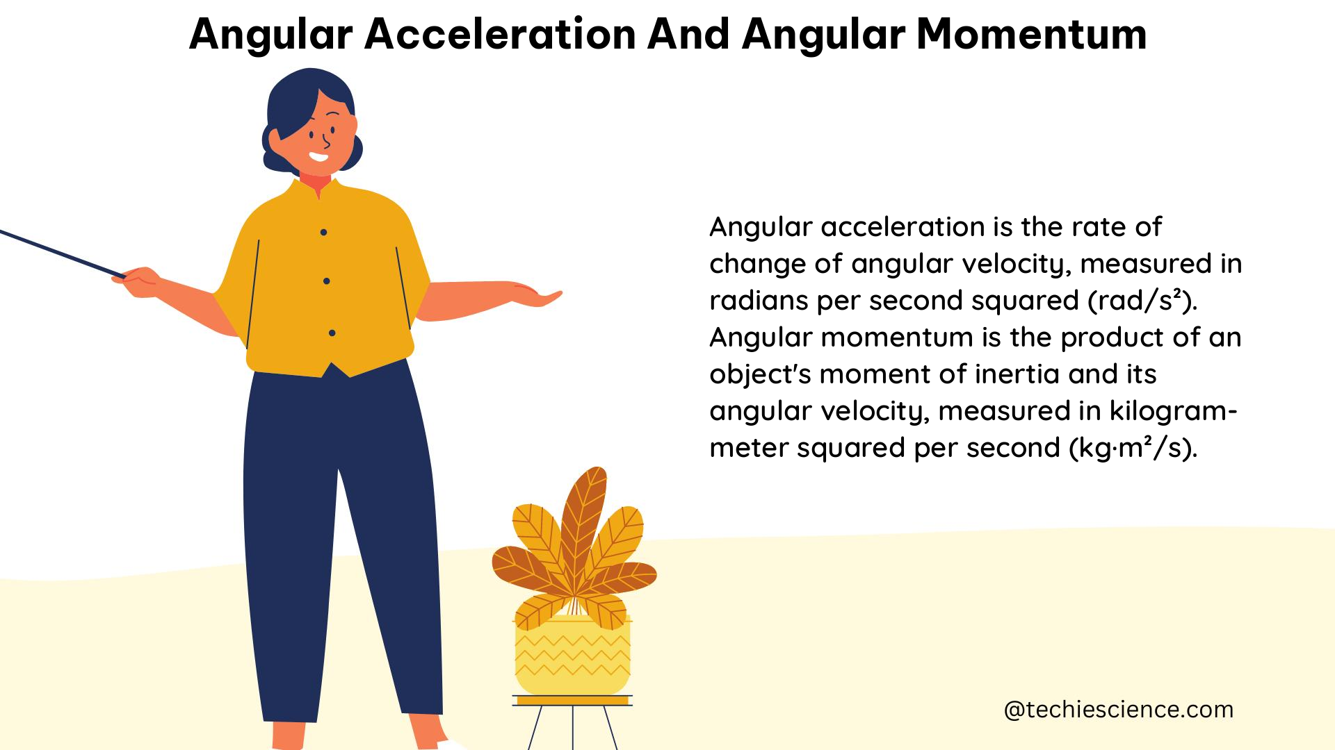
A Comprehensive Guide to Angular Acceleration and Angular Momentum

angular acceleration and angular momentum

Angular acceleration and angular momentum are fundamental concepts in the field of physics, particularly in the study of rotational motion. These two quantities are closely related and play a crucial role in understanding the behavior of objects undergoing rotational motion. In this comprehensive guide, we will delve into the intricacies of angular acceleration and angular momentum, providing a detailed exploration of their definitions, formulas, applications, and real-world examples.

Understanding Angular Acceleration

Angular acceleration is the rate of change of angular velocity with respect to time. It is a vector quantity, meaning it has both magnitude and direction. The magnitude of the angular acceleration vector is directly proportional to the rate of change of angular velocity, and its direction is perpendicular to the plane in which the rotation takes place.

The formula for angular acceleration is:

α = dω/dt

where:
α is the angular acceleration (in radians per second squared, rad/s²)
ω is the angular velocity (in radians per second, rad/s)
t is the time (in seconds, s)

The direction of the angular acceleration vector is determined by the right-hand rule. If the rotation is in the counterclockwise direction, the angular acceleration vector points in the direction of the thumb when the fingers of the right hand are curled in the direction of rotation.

Factors Affecting Angular Acceleration

The magnitude of the angular acceleration of an object depends on several factors:

  1. Net Torque: The net torque acting on the object is the primary factor that determines its angular acceleration. The greater the net torque, the greater the angular acceleration.
  2. Moment of Inertia: The moment of inertia of an object is a measure of its resistance to changes in its rotational motion. The greater the moment of inertia, the smaller the angular acceleration for a given net torque.
  3. Mass Distribution: The distribution of an object’s mass around its axis of rotation also affects its angular acceleration. Objects with a greater concentration of mass near the axis of rotation will have a smaller moment of inertia and, consequently, a larger angular acceleration for the same net torque.

Examples of Angular Acceleration

  1. Spinning Top: When a spinning top is released, it experiences a constant downward force due to gravity, which creates a net torque about the top’s axis of rotation. This net torque results in an angular acceleration, causing the top to slow down and eventually topple over.

  2. Bicycle Wheel: When a bicycle wheel is accelerated, the angular acceleration of the wheel is directed perpendicular to the plane of rotation, pointing in the direction of the wheel’s axis.

  3. Rotating Disk Experiment: In the context of Experiment 1, the angular position and velocity of a rotating disk are measured using a rotary motion sensor. The sensor records the angular position and velocity as the disk undergoes a constant angular acceleration.

Understanding Angular Momentum

angular acceleration and angular momentum

Angular momentum is a measure of the amount of rotation an object has, taking into account its mass, angular velocity, and the distribution of its mass around the axis of rotation. It is also a vector quantity, and its direction is the same as the direction of the angular velocity vector.

The formula for angular momentum is:

L = I * ω

where:
L is the angular momentum (in kilogram-meters squared per second, kg·m²/s)
I is the moment of inertia (in kilogram-meters squared, kg·m²)
ω is the angular velocity (in radians per second, rad/s)

The moment of inertia, I, is a measure of an object’s resistance to changes in its rotational motion. It depends on the object’s mass and the distribution of its mass around the axis of rotation.

Conservation of Angular Momentum

The angular momentum of a system is conserved unless there is a net external torque acting on the system. This means that the total angular momentum of a closed system remains constant over time, unless an external force or torque is applied.

Examples of Angular Momentum

  1. Spinning Figure Skater: When a figure skater pulls their arms in during a spin, their moment of inertia decreases, causing their angular velocity to increase in order to conserve angular momentum.

  2. Dropping Ring on Rotating Disk: In Experiment 2, a non-rotating ring is dropped onto a rotating disk. The conservation of the angular momentum of the system is verified by measuring the linear speed before and after the torque-free collision.

  3. Gyroscope: A gyroscope maintains its orientation due to the conservation of angular momentum. When a force is applied to the gyroscope, it resists the change in orientation, demonstrating the principle of angular momentum conservation.

Numerical Examples and Problems

  1. Calculating Angular Acceleration: A solid cylinder with a mass of 5 kg and a radius of 0.2 m is subjected to a constant net torque of 10 N·m. Calculate the angular acceleration of the cylinder.

Given:
– Mass (m) = 5 kg
– Radius (r) = 0.2 m
– Net Torque (τ) = 10 N·m

Moment of Inertia (I) for a solid cylinder:
I = (1/2) * m * r^2
I = (1/2) * 5 kg * (0.2 m)^2
I = 0.2 kg·m²

Angular Acceleration (α):
α = τ / I
α = 10 N·m / 0.2 kg·m²
α = 50 rad/s²

  1. Calculating Angular Momentum: A solid sphere with a mass of 3 kg and a radius of 0.1 m is rotating at an angular velocity of 20 rad/s. Calculate the angular momentum of the sphere.

Given:
– Mass (m) = 3 kg
– Radius (r) = 0.1 m
– Angular Velocity (ω) = 20 rad/s

Moment of Inertia (I) for a solid sphere:
I = (2/5) * m * r^2
I = (2/5) * 3 kg * (0.1 m)^2
I = 0.006 kg·m²

Angular Momentum (L):
L = I * ω
L = 0.006 kg·m² * 20 rad/s
L = 0.12 kg·m²/s

These examples demonstrate the application of the formulas and principles related to angular acceleration and angular momentum, providing a deeper understanding of these concepts.

Conclusion

Angular acceleration and angular momentum are fundamental concepts in the study of rotational motion. Understanding these concepts is crucial for analyzing the behavior of objects undergoing rotational motion, whether it’s a spinning top, a rotating bicycle wheel, or a figure skater in motion.

By exploring the definitions, formulas, and examples related to angular acceleration and angular momentum, we have gained a comprehensive understanding of these important physics principles. This knowledge can be applied to a wide range of real-world scenarios, from engineering applications to the analysis of sports and everyday activities.

As we continue to delve into the world of physics, the mastery of angular acceleration and angular momentum will undoubtedly prove invaluable in our pursuit of a deeper understanding of the physical universe.

References: