21 Facts on Plug Weld: The Complete Beginner’s Guide

plug weld

In this article, the subject “Plug Weld” with 21 Facts on Plug Weld will be discussing in a brief manner. Plug weld is also known as, Rosette weld.

The welding process of the plug is done when two metals are fused by the welds areas in younger circular holes. The plug weld method is done by the overlapping two metals. When two are overlapped in the top metal hole is created for deposition of the weld.

When spot weld cannot be performing in the metal in that case plug weld is done which can be occurring fairly at every moment.

What is plug weld?

The meaning of the plug weld is a stopper of a gap. Plug welds actually a round shaped weld. In the weld system of the plug two metals are overlapping with each other and a gap is present in one of the metal. The weld is credited in the gap to stop it. The wall of the gaps are remains straight but it is not required. The wall of the gaps can be bended too.

Plug weld symbol:

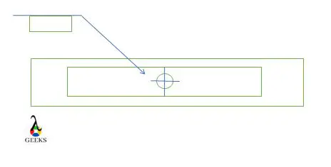
The symbol of the plug weld is a rectangle with a symbol of diameter situated to the side of the left of the weld symbol same as the number is combined with the symbol of diameter.

Plug Weld
Image – Plug Weld

Plug welds uses:

At modern engineering fields the plug weld are widely used in various sectors. A welder can easily handle the plug weld with a little exercise and learning. In the automotive sectors and aerospace plug weld is used.

Automotive sector:-

In the automotive sector where heavy machines are need to weld in that case the equipment of spot weld cannot be installed to perform for the insufficient space but as an alternative the plug weld easily can be installed there. The gaps of the machines can be easily welded by the plug weld. The strength of the plug weld is stronger than the spot weld.

Aerospace:-

To fill in the damages in the gaps on the components of the aerospace the plug weld is use. In the gaps of the exit cases and fans preciously filled without scrapping the whole system.

When to use plug weld?

In the sector of the automotive and aerospace where more precious and cleaned welding is require in that case plug weld is used instead of spot welding.

In automotive fields heavy machines are need to weld in that case the equipment of spot weld cannot be installed to perform for the insufficient space but as an alternative the plug weld easily can be installed there.

In the aerospace to filling the holes more accurate welding process is needed in that case plug weld is also used. Accuracy and strength of the plug is more than the spot weld.

Why to use plug weld?

Plug welds are circular shaped welds which are mainly used to corroborate two faces of the metal together by a small size space in one of the faces. In the field of the automotive plug welding is widely used as a substitute of spot welding when the equipment of the spot welding is gets insufficient area to operate.

The strength of the plug welding is more compare to the spot welding.

Plug weld hole size:

The minimum size of the diameter of the hole particularly for the plug should not be less than, the thickness of the part mixed with it plus 5/16(8 mm) ideally rounded to the following higher unaccompanied 1/16″. The highest width shall is same to the minimum width plus 1/8″(3 mm) or 2-1/4 times the thickness of the part, whichever is greater.

Plug weld joint:

In the industrial field with the help of the plug weld in generally five types of joints can be made, they are listed below,

  • Edge joint
  • Corner joint
  • Butt joint
  • Lap joint
  • Tee joint

Edge joint:-

Edge joint is not applicable for pressure and stress application. Edge joint can be explained as, when two edges of two different parts are joint with each other. The edge joint is appropriate for when the two sheets are adjacent and almost stays at parallel surface at the spot of the welding.

The different types of Edge joints are listed below,

  1. U groove weld
  2. V groove weld
  3. J groove weld
  4. Bevel groove weld
  5. Corner flange weld
  6. Square groove weld

Corner joint:-

Corner joint can be explained as; when two parts corners are situated to form a joint at the angle of right. With the two parts joining the shaped form like L.

The different types of Corner joints are listed below,

  1. Spot weld
  2. Bevel groove weld
  3. U groove weld
  4. V groove weld
  5. J groove weld
  6. Square groove weld
  7. Fillet weld
  8. Corner flange weld
  9. Edge weld
  10. Flare V groove weld

Butt joint:-

The easiest and simplest joint which is can make by the plug weld is butt joint. The butt joint is created by situated the two parts end section together. The two parts in the butt joint place in the same surface or one after another.

The different types of the Butt joint are listed below,

  1. Bevel groove weld
  2. U groove weld
  3. V groove weld
  4. J groove weld
  5. Square groove weld
  6. Flare bevel groove weld
  7. Flare V groove weld

Lap joint:-

With the help of lap joint mainly two different thickness metals can be joint with each other. Lap joint can be define as, when two parts are overlapping with each other. Lap joint can be double sided or single sided.

The different types of the Lap joint are listed below,

  1. Bevel groove weld
  2. J groove weld
  3. Slot weld
  4. Fillet weld
  5. Spot weld
  6. Flare bevel groove weld
  7. Plug weld

Tee joint:-

Tee joint can be explained as, when the two different parts are intersecting with each other at the angle of right and one part is lie at the other at the centre. Tee joint form like T letter.

The different types of the Tee joint are listed below,

  1. Plug weld
  2. Bevel weld
  3. Slot weld
  4. Fillet weld
  5. Melt through weld
  6. Flare bevel weld
  7. J groove weld

Plug welding thick steel:

The process done with the thick metal in plug welding is listed below,

  • Cleaning the thick steel
  • Marking on the top the thick steel
  • Holes are created on the top of the thick steel
  • Place the thick steels together
  • Placed the welding

Plug welds design and strength:

The strength of the plug weld is more than comparative to the spot weld. With the plug weld thick metals can be work. The design of the plug weld is not applicable for high force and stress.­­­­­­

How to calculate plug weld strength?

The process for calculating the strength of the plug weld is listed below,

  • The weld size and the weld strength are multiply with each other.
  • The highest permissible tensile strength is dividing with the above product.
  • The resultant should be multiply with the value of 0.77 to get the joint of the weld length.

Plug welding procedure:

The process of the plug welding is done in some steps. The steps are describe in below,

  • Step – 1: Cleaning the metal
  • Step – 2: Marking on the top metal
  • Step – 3: Holes are created on the top metal
  • Step – 4: Place the top metal and base metal together
  • Step – 5: Placed the welding

Step – 1: Cleaning the metal:-

In the beginning of the plug welding at first the pre preparation is done. In this step the base metal need to clean up thus any dirt or impurities cannot takes place during the welding process and also cleaning is important after the welding  method no defect is present. Safety is very important while welding process. Welding gloves, welding helmet, should be wear by the welder to prevent accident. At last welding burn is not desire during the plug welding process.

Step – 2: Marking on the top metal:-

In the next step of the plug welding marking is done on the top section of the base metal. If multiple plugs welding are done in the base metal in that case requires to be spaced out on a level.

Step – 3: Holes are created on the top metal:-

After marking, the holes are created in which places where the plug welding will be created. In the various ways hole can be done in the base metal among them drilling is most common process chosen by the welders to create holes.

Step – 4: Place the top metal and base metal together:-

After completingmarking the metal should be placed together thus they cannot move during the process. A plug weld clamp is use to clamp the metals at one place.

Step – 5: Placed the welding:-

At the last of the process weld is placed. When the welding is placed the most important criteria need to remember that, the process should be start on the external side along the points of the edges, the way of the working will be towards the middle. The strength of the metal will be increases and chances of the defect will be decreases by this process and also the temperature of the base metal is rise up to the temperature of the top metal.

Can plug welds be used in tension?

No, plug welds cannot be used in tension.

The dimensions which are applied for the symbol of the plug weld are listed below,

  1. Depth of filling
  2. Size
  3. Angle of counter stroke
  4. Number of the welds
  5. Spacing of the welds

How to plug weld sheet metal?

The process of the plug welding in the sheet metal is done in some steps. The steps are describe in below,

  • Cleaning the sheet metal
  • Marking on the top the sheet metal
  • Holes are created on the top of the sheet metal
  • Place the sheet metal together
  • Placed the welding

Cleaning the sheet metal:-

In the beginning of the plug welding at first the pre preparation is done. In this step the sheet metal need to clean up thus any dirt or impurities cannot takes place during the welding process and also cleaning is important before the welding  method no defect is present.

Marking on the top the sheet metal:-

In the next step of the plug welding marking is done on the top section of the sheet metal. If multiple plugs welding are done in the sheet metal in that case requires to be spaced out on a level.

Holes are created on the top of the sheet metal:-

After marking, the holes are created in which places where the plug welding will be created. In the various ways hole can be done in the base metal among them drilling is most common process chosen by the welders to create holes. Mostly 8 mm – 10 mm hole is doing. The hole diameter depend on the flange width and the distance keep between the holes are near about 25 mm.

Place the sheet metal together:-

After completingmarking the metal should be placed together thus they cannot move during the process. A plug weld clamp is use to clamp the metals at one place.

Placed the welding:-

At the last of the process weld is placed. When the welding is placed the most important criteria need to remember that, the process should be start on the external side along the points of the edges, the way of the working will be towards the middle. The strength of the metal will be increases and chances of the defect will be decreases by this process and also the temperature of the base metal is rise up to the temperature of the top metal.

Plug weld vs. slot weld:

The major differences in between the plug weld and slot weld are describe below,

Plug weldSlot weld
A weld made in a circular hole in one member of a joint fusing that member to another member. A fillet-welded hole is not to be construed as conforming to this definition.A slot weld joins the surface of a piece of material to another piece through an elongated hole. The hole can be open at one end and can be partially or completely filled with weld material.
The shape of the plug weld can be identified with the help of diameter.The shape of the slot weld can be identified with the help of the both length and diameter.
Application of the plug weld is,
1. Manufacturing the body of the automotive 2. Repairing the body of the automotive
3. Welding tubes inside a pipe
4. To join different thickness metal
Application of the slot weld is,
1. Dispatch the shear force in lap joints
2. Stopping buckling in overlapped portions.

Puddle weld vs. plug weld:

The major differences in between the plug weld and puddle weld are describe below,

Plug weldPuddle weld
The welding process of the plug is done when two metals are fused by the welds areas in younger circular holes.A type of plug welds for joining two sheets of light-gauge material; a hole, burned in the upper sheet, is filled with a puddle of weld metal to fuse the upper sheet to the lower.
Thick material can work with the plug weld.Thick material could not work with puddle weld.

Plug weld vs. spot weld:

The major differences in between the plug weld and spot weld are describe below,

Plug weldSpot weld
The welding process of the plug is done when two metals are fused by the welds areas in younger circular holes. The plug weld method is done by the overlapping two metals. When two are overlapped in the top metal hole is created for deposition of the weld.  Spot welding process can be explain as, welding together two or more than two metals with the help of heat and pressure into the area of the weld from an electric current.
The strength of the plug weld is more than the spot weld.The strength for the spot weld is comparative less than the plug weld.
Technical cost is low.Technical cost is high.
Accuracy of the plug weld is more.Accuracy of the spot weld is less comparative to the spot weld.
For the repairing of the automotive body panel plug weld is used.For the assembly of the automotive body panel spot weld is used.

Necessity of space in plug socket weld:

With the help of space between the two plates in the plug socket weld the quality of the weld can be easily determine. If gap is present in between two plates then it’s called good plug socket weld and if gap is not present in between two plates then it’s called bad plug socket weld.

The space of the plug socket weld is used to minimize the crakes while the plates are gets warmer to absorb the excess amount of temperature during the welding process.

Conclusion:

If skilled welder with a little learning can work with plug weld then it is very advanced and suitable process to weld. The strength of the plug weld is good enough to weld.
23 Facts on Hoop Stress: The Complete Beginner’s Guide

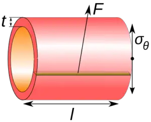
386px Circumferential stress.svg 300x242 1

In this article, the topic, “hoop stress” with 23 Facts on Hoop Stress will be discussed in a brief portion. In the outer radius or inner radius portion of a tube hoop stress is remains maximum.

The calculation of the hoop stress is estimate the stress which is acted on a thin circumference pressure vessel. For estimate the hoop stress in a sphere body in some steps. The steps are listed below,

  • The internal diameter of the yard and internal pressure should be multiply at the beginning of the process.
  • In the next step the resultant should be divided four times with the thickness of the shell.
  • In final stage divide the resultant with the joint efficiency.
hoop stress
Image – Components of hoop stress; Image Credit – Wikipedia

What is hoop stress?

The hoop stress can be explain as, the stress which is produce for the pressure gradient around the bounds of a tube. The maximum amount of hoop stress is appearing in the outer radius and inner radius of the tube. The hoop stress depends upon the way of the pressure gradient.

The reason behind the hoop stress is, when a cylinder is under the internal pressure is two times of the longitudinal stress. In a tube the joints of longitudinal produced stress is two times more than the circumferential joints. If pressure is applied in a tube uniformly then the hoop stress in the length of the pipe will be uniform.

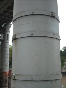
450px Wrought iron straps Chepstow Railway Bridge
Image – Cast iron pillar of Chepstow Railway Bridge, 1852. Pin-jointed wrought iron hoops (stronger in tension than cast iron) resist the hoop stresses; Image Credit – Wikipedia

What is hoop stress in pressure vessel?

The hoop stress in a pressure vessel is acted perpendicular to the direction to the axis. Hoop stresses are generally tensile. The hoop stress is appearing for resist the effect of the bursting from the application of pressure.

Mathematically can written for hoop stress in pressure vessel is,

σθ = P.Dm/2t

Where,

σθ = Hoop stress

P = Internal pressure of the pressure vessel

Dm= Mean diameter of the pressure vessel

t = Thickness of the wall of the pressure vessel

For thin walled pressure vessel the thickness will be assumed as one tenth of the radius of the vessel not more than of it.

In the system of the Inch – pound – second the unit for the internal pressure of the pressure vessel express as ponds – force per square inch, unit for Mean diameter of the pressure vessel is inches, unit for thickness of the wall of the pressure vessel inches and, In the system of the S.I. unit for the internal pressure of the pressure vessel express as Pascal, and unit for Mean diameter of the pressure vessel is meter, unit for thickness of the wall of the pressure vessel meter.

What is hoop stress in pipelines?

Hoop stress in pipelines can be explain as, the stress in a wall of a pipe operable circumferentially in a profile perpendicular to the axis of the longitudinal of the tube and rose by the tension of the fluid substance in the pipe.

The hoop stress actually is a function which is go about to tension the pipe separately in a direction of the circumferential with the tension being created on the wall of the pipe by the internal pressure of the pipe by natural gas or other fluid.

The hoop stress increases the pipe’s diameter, whereas the longitudinal stress increases with the pipe’s length. The hoop stress generated when a cylinder is under internal pressure is twice that of the longitudinal stress.

Hoop stress formula:

The formula of the Barlow’s is used for estimate the hoop stress for the wall section of the pipe.

The formula for the hoop stress can be written as,

 σθ = P.D/2t

Where,

σθ = Hoop stress

P = Internal pressure of the pipe

D = Diameter of the pipe

t = Thickness of the pipe

In S.I. unit, P (the internal pressure of pipe) expresses as Pascal, and unit for D (diameter of the pipe) is meter, unit for t (thickness of the wall of the pipe) is meter. In the system of the Inch – pound – second unit, P (the internal pressure of pipe) expresses as ponds – force per square inch, and unit for D (diameter of the pipe) is inches, unit for t (thickness of the wall of the pipe) is inches.

Hoop stress formula for thick cylinder:

Tangential stress and radial stress in a cylinder with thick walled tubes or cylinder with internal pressure, external pressure with closed ends.

Hoop stress formula in the case of thick cylinder three sections. The three sections are listed below,

  • Hoop stress in the direction of the axial
  • Hoop stress in the direction of the circumferential
  • Hoop stress in the direction of the radial

Hoop stress in the direction of the axial:-

The hoop stress in the direction of the axial at a particular point in the wall of the cylinder or tube can be written as,

gif

Where,

σa= Hoop stress in the direction of the axial and unit is MPa, psi.

pi = Internal pressure for the cylinder or tube and unit is MPa, psi.

ri = Internal radius for the cylinder or tube and unit is mm, in.

po = External pressure for the cylinder or tube and unit is MPa, psi.

ro = External radius for the cylinder or tube and unit is mm, in.

Hoop stress in the direction of the circumferential:-

The hoop stress in the direction of the circumferential at a particular point in the wall of the cylinder or tube can be written as,

gif

Where,

σc = The hoop stress in the direction of the circumferential and unit is MPa, psi.

pi = Internal pressure for the cylinder or tube and unit is MPa, psi.

ri = Internal radius for the cylinder or tube and unit is mm, in.

po = External pressure for the cylinder or tube and unit is MPa, psi.

ro = External radius for the cylinder or tube and unit is mm, in.

r = Radius for the cylinder or tube and unit is mm, in. (ri < r < ro)

Maximum hoop stress for the cylinder or tube is, ri = r

Hoop stress in the direction of the radial:-

The hoop stress in the direction of the radial at a particular point in the wall of the cylinder or tube can be written as,

gif

Where,

σr = The hoop stress in the direction of the radial circumferential and unit is MPa, psi.

pi = Internal pressure for the cylinder or tube and unit is MPa, psi.

ri= Internal radius for the cylinder or tube and unit is mm, in.

po = External pressure for the cylinder or tube and unit is MPa, psi.

ro = External radius for the cylinder or tube and unit is mm, in.

Hoop stress formula for pipe:

The formula of the Barlow’s is used for estimate the hoop stress for the wall section of the pipe.

The formula for the hoop stress can be written as,

σθ = P.D/2t}

Where,

σθ] = Hoop stress

P = Internal pressure of the pipe

D = Diameter of the pipe

t = Thickness of the pipe

In S.I. unit, P (the internal pressure of pipe) expresses as Pascal, and unit for D (diameter of the pipe) is meter, unit for t (thickness of the wall of the pipe) is meter.

In the system of the Inch – pound – second unit, P (the internal pressure of pipe) expresses as ponds – force per square inch, and unit for D (diameter of the pipe) is inches, unit for t (thickness of the wall of the pipe) is inches.

Hoop stress formula for sphere:

The hoop stress formula for the sphere is discussed in below section,

  • Hoop stress formula for sphere in thin walled section
  • Hoop stress formula for sphere in thick walled section
  • Hoop stress formula for sphere in thick walled section (Only for internal pressure)
  • Hoop stress formula for sphere in thick walled section (Only for external pressure)

Hoop stress formula for sphere in thin walled section:-

Thin walled portions of a spherical tube or cylinder where both internal pressure and external pressure acted can be express as,

Pr/2t

Hoop stress formula for sphere in thick walled section:-

Thick walled portions of a spherical tube and cylinder where both internal pressure and external pressure acted can be express as,

gif

Hoop stress formula for sphere in thick walled section (Only for internal pressure):-

Thick walled portions of a tube and cylinder where only internal pressure acted can be express as,

gif

Hoop stress formula for sphere in thick walled section (Only for external pressure):-

Thick walled portions of a tube and cylinder where only external pressure acted can be express as,

gif

Where,

σh = The hoop stress and unit is MPa, psi.

P = Pressure under consideration and unit is MPa, psi.

pi = Internal pressure for the cylinder or tube and unit is MPa, psi.

ri = Internal radius for the cylinder or tube and unit is mm, in.

po = External pressure for the cylinder or tube and unit is MPa, psi.

ro = External radius for the cylinder or tube and unit is mm, in.

r = Radius for the cylinder or tube and unit is mm, in.

t = Wall thickness for the cylinder or tube and unit is mm, in.

Hoop stress formula for conical cylinder:

Hoop stress formula for conical cylinder can be express for two conditions. The conditions are listed below,

  • When the liquid substance is stays at the surface of below y (y < d)
  • When the liquid substance is stays at the surface of above y or equal to y (y >d, y = d)

Case: 1: When the liquid substance is stays at the surface of below y (y < d):-

Meridional stress:

σ1 = δytanα/2tcosα (d-2y/3)

Hoop stress or circumferential stress:

gif

Radial Displacement of circumference :

gif

Change in the height of dimension y:

gif

Turning of a meridian out of its unloaded condition:

gif

Case: 2: When the liquid substance is stays at the surface of above y or equal to y (y >d, y = d):-

Meridional stress:

gif

Hoop stress or circumferential stress:

σ2 = 0

Radial Displacement of circumference:

gif

Change in the height of dimension y:

gif

Turning of a meridian out of its unloaded condition:

gif

Where,

σ1 = Hoop stress and unit is lbs/in2

σ2 = Hoop stress and unit is lbs/in2

E = Modulus of Elasticity and unit is lbs/in2

ψ = Turning of a meridian out of its unloaded condition.

v = Poisson’s ratio and it is unit less.

Δ= Liquid density and unit is lbs/in3

d = Liquid fill level and unit is in.

t = Wall thickness unit is in.

α = Angle and unit degree.

y = Pointing a level of a cone and unit is in.

Hoop stress formula derivation:

Another term for the cylindrical tube is pressure vessel. In various fields of engineering the pressure vessels are used such as, Boilers, LPG cylinders, Air recover tanks and many more.

Derivation of the hoop stress formula:-

Cylindrical shell bursting will take place if force due to internal fluid pressure will be more than the resisting force due to circumferential stress or hoop stress developed in the wall of the cylindrical shell.

Let consider the terms which explaining the expression for hoop stress or circumferential stress which is produce in the cylindrical tube’s wall.

P = Internal fluid pressure of the cylindrical tube

t = Thickness for the cylindrical tube

L= Length for the cylindrical tube

d = Internal diameter for the thin cylindrical tube

σH = Hoop stress or circumferential stress which is produce in the cylindrical tube’s wall

Force produce for the internal fluid pressure = Area where the fluid pressure is working * Internal fluid pressure of the cylindrical tube

Force produce for the internal fluid pressure = (d x L) x P

Force produce for the internal fluid pressure = P x d x L …….eqn (1)

Resulting force for the reason of hoop stress or circumferential stress = σH x 2Lt …….eqn (2)

From the …….eqn (1) and eqn (2) we can write,

Force produce for the internal fluid pressure = Resulting force for the reason of hoop stress or circumferential stress

P x d x L = σH x 2Lt

σH= Pd/2t

How to calculate hoop stress?

For calculating the hoop stress for a sphere body the steps are listed below,

  • The internal diameter of the yard and internal pressure should be multiply at the beginning of the process.
  • In the next step the resultant should be divided four times with the thickness of the shell.
  • In final stage divide the resultant with the joint efficiency.

How to calculate hoop stress in pipe?

For calculating the hoop stress just need to multiply the internal diameter (mm) of the pipe with internal pressure (MPa) of the pipe and then the value need to divided with the thickness (mm) of the pipe with 2.

Formula for estimate the hoop stress in a pipe is,

Hoop stress = Internal diameter x Internal pressure/2 x Thickness

Mathematically hoop stress can be written as,

σθ= P.D/2t

Where,

σθ = Hoop stress

P = Internal pressure

D = Diameter of the pipe

t = Thickness of the pipe

How to calculate hoop stress of a cylinder?

Hoop stress can be explained as; the mean volume of force is employed in per unit place. The hoop stress is the capacity is applied circumferentially in both ways on every particle in the wall of the cylinder.

Formula for estimate the hoop stress of a cylinder is,

Hoop stress = Internal diameter x Internal pressure/2 x Thickness

Mathematically hoop stress can be written as,

σθ = P.D/2t

Where,

σθ = Hoop stress in the direction of the both and unit is MPa, psi.

P = Internal pressure of the pipe and unit is MPa, psi.

D = Diameter of the pipe and unit is mm, in.

t = Thickness of the pipe and unit is mm, in.

Hoop stress vs. radial stress:

The major difference between hoop stress and radial stress are describe in below section,

Hoop stress Radial stress
Hoop stress can be explained as; the mean volume of force is employed in per unit place. The hoop stress is the capacity is applied circumferentially in both ways on every particle in the wall of the cylinder.   Radial stress can be explained as; stress is in the direction of or away from the central axis of a component.
Mathematically hoop stress can be written as,
σh= P.D/2t
Where,
P = Internal pressure of the pipe and unit is MPa, psi.
D = Diameter of the pipe and unit is mm, in.
t = Thickness of the pipe and unit is mm, in.  
Mathematically radial stress can be written as,
gif Where,
σr= The radial stress and unit is MPa, psi.
pi = Internal pressure for the cylinder or tube and unit is MPa, psi.
ri = Internal radius for the cylinder or tube and unit is mm, in.
po = External pressure for the cylinder or tube and unit is MPa, psi.
ro = External radius for the cylinder or tube and unit is mm, in.
r = Radius for the cylinder or tube and unit is mm, in.
 
The hoop stress usually much larger for pressure vessels, and so for thin-walled instances, radial stress is usually neglected. The radial stress for a thick-walled cylinder is equal and opposite of the gauge pressure on the inside surface, and zero on the outside surface.

Hoop stress vs. axial stress:

The major difference between hoop stress and axial stress are describe in below section,

Hoop stress Axial stress
The hoop stress, or tangential stress, is the stress around the circumference of the pipe due to a pressure gradient. The maximum hoop stress always occurs at the inner radius or the outer radius depending on the direction of the pressure gradient. Axial stress describes the amount of force per unit of cross-sectional area that acts in the lengthwise direction of a beam or axle. Axial stress can cause a member to compress, buckle, elongate or fail.
Mathematically hoop stress can be written as, σh= P.D/2t Mathematically axial stress can be written as,
σa = F/A= Pd2/(d + 2t)2 – d2 
Hoop stress is not a shear stress. Axial stress is a shear stress.

Hoop stress vs. tangential stress:

The major difference between hoop stress and tangential stress are describe in below section,

Hoop stressTangential stressThe hoop stress in a pressure vessel is acted perpendicular to the direction to the axis. Hoop stresses are generally tensile. The hoop stress is appearing for resist the effect of the bursting from the application of pressure.   When the direction of the deforming force or external force is parallel to the cross-sectional area, the stress experienced by the object is called tangential stress.
Hoop stress is not a shear stress. Tangential stress is a shear stress.

Hoop stress vs. yield strength:

The major difference between hoop stress and yield strength are describe in below section,

Hoop stress Yield strength
Hoop Stress define as, the pipe material stress tangential to the pipe. In a properly supported round pipe containing a fluid under pressure the largest tensile stress is the hoop stress.   Yield Stress defines as, yield strength or yield stress is the material property defined as the stress at which a material begins to deform plastically whereas yield point is the point where nonlinear (elastic + plastic) deformation begins.  

Is hoop stress shear stress?

No, hoop stress or circumference stress is not a shear stress. In the theory of pressure vessel, any given element of the wall is evaluated in a tri-axial stress system, with the three principal stresses being hoop, longitudinal, and radial. Therefore, by definition, there exist no shear stresses on the transverse, tangential, or radial planes.

Is hoop stress tensile?

Hoop stress can be explained as; the stress is developed along the circumference of the tube when pressure is acted.

Yes, hoop stress is tensile and for this reason wrought iron is added to various materials and has better tensile strength compare to cast iron. Hoop stress is works perpendicularly to the direction of the axial. Hoop stresses are tensile, and developed to defend the effect of the bursting that appears from the movement of pressure.

Is hoop stress a principal stress?

Yes, hoop stress is the principal stresses. To estimate the longitudinal stress need to create a cut across the cylinder similar to analyzing the spherical pressure vessel. The form of failure in tubes is ruled by the magnitude of stresses in the tube. 

If there is a failure is done by the fracture, that means the hoop stress is the key of principle stress, and there are no other external load is present.

Is hoop stress normal stress?

Yes, hoop stress or circumferential stress is a normal stress in the direction of the tangential. Stress is termed as Normal stress when the direction of the deforming force is perpendicular to the cross-sectional area of the body. The length of the wire or the volume of the body changes stress will be at normal.

How to reduce hoop stress?

The method is to reducing the hoop stress is control a strong wire made with steel under tension through the walls of the cylinder to shrink one cylinder over another.

The most efficient method is to apply double cold expansion with high interference along with axial compression with strain equal to 0.5%. This technique helps to reduce absolute value of hoop residual stresses by 58%, and decrease radial stresses by 75%.

Conclusion:

  • A normal stress in tangential direction horizon of the cylinder surface.
  • Hoop stress also called as, Circumferential stress.
  • Hoop stress acts along φ.

Fillet Weld: What, Symbol, Diagram, Process, Machine, Strength And Several Facts

11 1

Fillet Weld is a continuous weld joint used to connect two metal pieces which are making an angle, in most of the cases a 90 degree angle to each other.

The Fillet welds may attain triangular, concave, convex or flat shape due to the influence of the welding technique. Most frequently used weld type in fabrication industries which covered a wide range(almost 70-80%) of joints prepared by arc welding method.

Non fusion processes like brazing and soldering are also used for fillet welded joint.

Fillet welds are seen as T joints where two metal pieces are connected to each other making a right angle and also seen as lap joints where one piece of metal overlap the other piece of metal.

What is a Fillet Weld?

A Fillet weld requires less edge preparation and has an almost triangular cross section.

Fillet Weld is very cost effective as well as a simple joining method, that’s why one of the most widely used weld type in the fabrication industry. The different arc welding processes like metal arc, tungsten arc, shielded metal arc etc are adopted to get a fillet weld.

440px Fillet Weld Notation 3
Fillets ;Image Credit: Wikipedia

Fillet Weld example

In welding industry, fillet weld joint are most frequently used for different purposes.

Generally welders prefer fillet welds when want to connect flanges to pipes, welding cross sections of infrastructures and to replace bolts since they are not strong enough and having high chances of wear off.

Fillet Weld joint

Fillet Weld Joint occurs when two metal surfaces or other shapes are joined or welded to each other perpendicularly or at an angle.

Tee joint, lap joint, corner joint all are come under fillet weld joint. Fillet welds attain the appearance of a triangle, and depending on welder’s technique and different parameters, they can have concave, flat or convex surface.

The symbols also gives dimensions of the weld in different ways like leg length, length of the weld, spaces between the  welds. The strength of the weld is also mentioned using a letter and a number combination just like E60.

Fillet Weld symbols

The basic symbol for Fillet Weld is in the shape of a triangle consisting of a reference line and an arrow and a tail.

The triangle lies either below or above the reference line, the arrow head always points towards the weld location. The tail is an optional element of the symbol which gives the in formations regarding the weld.

In ISO 2553,A system one continuous and one dashed line placing parallel to each other are used as reference line. If a symbol consists of a single reference line with a triangle above the line, it indicates the weld is going to be on the opposite side of the arrow.

If a joint consists of two fillets then an arrow with two triangles above and below the reference line is used for indication. For a continuous weld around the joint, then a small circle is placed around the junction point of the reference line and the arrow pointing to the joint.

To describe the aesthetics of the weld, different symbols are there. For a concave shaped weld, a simple curve pointing away from the hypotenuse of the fillet triangle and for a convex weld a curve towards hypotenuse is used for representation.

Fillet Weld Parts

Commonly used joint designs for Fillet Welds are Tee Joint, Lap Joint and Corner Joint, in each of the joints the two surfaces at an right angle to each other.

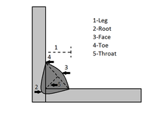
The different parts of a fillet joint can be explained with the help of a figure below:

Fillet Weld
Different Parts of a Fillet Joint; Image Credit: Wikipedia

The parts of a Fillet weld can be seen in the above figure: Leg, Root, Face, Toe and Throat. The length (5) represents the throat thickness, distance between the centre point of the face surface of the fillet to the root of the fillet joint.

Throat thickness should be equal to the thickness of the metal piece to be welded. Using throat length, we can calculate the strength that can be withstand by a fillet joint.

The leg length(1) represents the two sides of the triangular fillet. To specify the size of a weld, leg length of the fillet is used. Face(3) gives the outer look of the weld, root(2) represents the deepest penetration part.

How to Measure Fillet Weld Size?

In a technical drawing, the symbol for Fillet might consist of weld dimensions.

We can define the weld size differently like the length of the weld, size of the legs, the measurement of the gap between the welds.

In a symbol, the size of the leg is placed in the left, for a fillet joint with unequal leg size we have to mentions both the dimensions like 1″ x 1.3″. On the other hand for a weld with equal leg sizes, single dimension is enough for representation.

In the right side of the fillet triangle we mention the length of the weld. In case of a double fillet the sizes are mentioned separately for both sides of the joint. If the fillet weld is not continuous, the length and pitch between centre of intermittent fillets are mentioned to the right of the symbol.

Fillet Weld Size Formula

Calculation of minimum and maximum Fillet weld size is necessary to endure the maximum stresses acting on a weld.

We always prefer an optimum value for a welded joint, an accurate calculation to get a correct fillet weld size is necessary. If a designer goes for a weld size above the optimum value, it does not add strength to the welded joint instead a hike in weld metal, man power and cost is observed.

To decide the leg length of a fillet weld always we have to remember that minimum leg size should be 3/4th of the plate thickness and for unequal plate thickness consider the thinner one.

Minimum Fillet weld size= 3/4th, t= fillet thickness, considering both side welded fillet joint with full length fillet weld. For only one side Fillet leg length should be doubled.

Effective Length of Fillet Weld

Site adaptability and ease of fabrication are the advantages which make a fillet joint abandon one One member overlaps the other therefore require less precision while fitting.

To calculate the effective length of the fillet we have to subtract two times the fillet size from the total length of the fillet weld.

Effective Length of Fillet, leff = l – 2 . Z

leff must have a minimum value of four times the weld size, leff > 4 . Z

The length of a weld shown in a diagram is considered as effective length of the weld and 2 . Z is the extra length provided by the welder.

Throat Thickness of Fillet Weld

The cross sectional of a fillet weld can be represented by a right angled triangle and, the perpendicular distance of the hypotenuse from the intersection point of legs is known as throat thickness.

The step by step method to calculate throat thickness is mentioned below:

12
Cross sectional view of a Fillet Weld

In the above figure, for triangle ABC, Z= leg size or size of the weld

BD= throat thickness=t

Length of weld=l

The minimum area of the throat is obtained at the throat BD, which is given by product of t and Z.

Now t= z cos 450 Or 0.707 Z

Minimum area of the weld or throat area

A= throat thickness X length of weld=0.707 Z l

If σt is allowable tensile stress for the weld metal then the tensile strength of the joint for single fillet

P=Throat area x allowable tensile strength=

The joint with double fillet,

Fillet Weld design

Though Fillet joints are very common but different aspects are to be considered before producing such a weld.

The throat thickness and leg size should always be within a specific range for a perfect fillet weld.

It is little bit difficult to achieve the correct weld size maintaining required leg length and throat thickness. Generally designers allow a safety factor when calculating the size, therefore the weld size mentioned in a fabrication drawing is generally larger than the required design size

11 1
Different Designs of Fillet Joints

Fillet welds can be précised by two terms, Z= weld size or leg size and t= throat size.

Throat is the minimum cross section of the weld located at 450 to the leg size.

Now t= z cos 450 Or 0.707 Z

The size of a weld is specified by its leg size(Z).

A parallel Fillet Weld is subjected to shear failure at the throat section,

The strength of a single fillet weld is

Where l= length of the complete weld

gif

= maximum permissible shear stress

P = load acting on the plates.

Transverse Fillet Weld

Fillet Joints are of two types: Transverse Joint and Parallel Joint. The main purpose of design a Transverse Fillet Joint is to withstand the tensile strength.

In Transverse Fillet weld the direction of weld is perpendicular to the direction of the force acting on the joint and in Parallel joint the direction of weld is parallel to the direction of the force acting on the joint. Transverse weld can be subdivided into single and double transverse fillet weld.

A single transverse joint may warp out of the shape from the edge which one is not welded, this is the main drawback of a single transverse fillet.In transverse Fillet Weld the load is considered as tensile because the load is perpendicular to the weld.

Load carrying capacity or strength of the weld is σt = F/A where

σt= tensile strength of the weld

F= Force the weld can handle

A=the effectivearea of the weld

The effective considering both the legs are equal, the theoretical throat will be z cos 450

Or 0.707 Z

For all fillet joints, area can be calculated by multiplying throat of the weld to length of leg(z) of the weld.

If σt is the allowable tensile stress of the weld material , then tensile strength of the single transverse fillet weld is

P= throat area x allowable tensile stress

P = 0. 707Z . l . σt

For double transverse fillet weld

P = 2 x 0. 707Z . l . σt

Fillet weld Vs Buttweld

The differences between Fillet and Butt welds are mentioned below:

FilletButt
Suitable for automatic welding situations.Due to groove preparation before welding, automatic processes are not applied.
Abandon in welding industry due to no need of extensive joint preparation.Sometimes avoided due to compulsory edge preparation.
Require higher heat input than the butt weld for same thickness of metal plateRequire lesser heat input than fillet joint for same metal thickness.
Fillet Vs Butt Weld

Fillet Weld Size Formula

Distortion is a common disorder associated with welded joints, main reasons of distortion are thermal expansion and contraction of weld material and base material during welding.

Symmetrical weld reduces distortion but adaptation of symmetrical weld in each case is not possible. Over welding also causes distortion.

In European countries the technical drawings for a fillet joint mention the throat size and in UK generally leg size is mentioned. For a fillet weld with equal leg lengths, the cross-section triangle is a right-angle triangle with angles of 45 degrees in each corner.

The relation between throat size and leg size is mentioned below:

gif

If\\tau is the allowable shear stress of the weld material , then shear strength of the single parallel fillet weld is

 P= throat area x allowable shear stress=

For double parallel fillet weld

The tensile strength calculation formulae for transverse fillet weld are mentioned above (heading transverse fillet weld).

Generally, Fillets should be designed to withstand shearing stress. For a fillet joint with equal legs, the throat thickness is 0.707 times the leg size which gives a weld area equal to the throat dimension times the length of the weld.

How to use a Weld Fillet Gauge?

The two main uses of a Fillet Weld Gauge is to measure the leg length and to check the throat thickness.

Reading a Fillet Gauge is quite simple and very clear cut without any complexity. Each end of the gauge measures both leg length and throat thickness. The convex sides calculate the leg length and the sides with protrusions in the middleof a Welding Fillet Gauge calculate the throat thickness.

Depending on the type of fillet joint we have to decide the side of the gauge used to measure. Excessive convexity should always be avoided since the high convexity of a joint add to the stress risers and leads to crack and weld failures.

In the case of a concave weld, the weld size is measured using the side of the weld gauge where the center tab is required to touch the weld face. The thickness of deepest penetration part is difficult to measure since it is in the heat affected zone and difficult to define its extent precisely.

Conclusion:

To wrap up our post we can state that a thorough knowledge of fillet weld design is necessary for an Engineer. An appropriate weld symbol is necessary to represent the weld size. In UK, the leg length is specified by ‘Z’ in EN ISO 2553 and the number gives the weld size in millimeters.

Bevel Weld: What, Diagram, Symbol, Process, Machine, Strength, And Several Facts

Flare bevel

This article discusses about flare bevel weld. . Bevelling is a process of removing some material from the base metal for the weld metal to flow in easily.

The welds made after bevelling are called as bevel weld. This article will discuss about flare bevel weld. First we will discuss about what is a flare bevel weld then discuss about its design, symbol, size etc.

What is a flare bevel weld?

A flare bevel weld is a type of bevel weld made between a curved surface and a flat surface, when two curved surfaces are there then it will be called as flare V groove weld.

In this type of bevel weld, bevelling is not required as such because the gap between curved surface and flat surface acts as the valley which we create using bevelling. Hence no more material needs to be scraped out as the valley already exists. The weld metal seeps inside this valley.

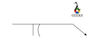
Flare bevel weld symbol

There are many types of weld used in industry. These welds are represented by symbols. The symbol which represents flare bevel weld is given below-

flare bevel weld
Image: Flare Bevel Weld

Flare bevel weld size

The size of the flare bevel is slightly different than bevel weld. We can measure the leg length of the flare groove.

A minimum leg length is specified based on the type of joint. A weld that is filled till atleast the specified minimum leg length or even higher will suffice the job. The flare bevel weld size is written inside the parenthesis just like the size written for other bevel welds.

Flare bevel weld examples

The flare bevel weld is made between a radial surface and a flat surface. The most common examples of flare bevel weld is discussed in the section below.

  • Welding of two pipes– It is done in such a way that the flat surface is connected to the round surface. This is done for making branches in pipe network. The flat end of the pipe is cut in such a way that it makes the desired angle with the second pipe on which it is going to be welded.
  • Trophies– Some trophies have a complicated design where a circular surface stand on a flat surface. For wooden trophies this can be done by making slots. But for metallic trophies flare weld can be done to serve this purpose.
  • Rod holder- In many applications where a rod needs to be held on a flat surface, a holder is welded on the flat surface inside which the rod can be inserted. The

Flare bevel weld joint

A flare bevel weld joint is simply the joint made by flare bevel weld. This is done to join a work piece with flat surface to another work piece with round surface.

Beveling is not required in this type of weld because the round surface makes a cavity like structure with the flat surface, the molten metal seeps inside this cavity so that it can make stronger bonds easily.

Flare bevel weld design

The flare bevel welds are made for joining a flat surface with a work piece having round surface. The design procedure is similar to design of other welds.

While designing the weld we need to keep in mind that the weld strength is more than the strength of the work pieces. The welds design depends on the type of force that the weld needs to sustain. The required area is calculated using the permissible stress value.

Double flare bevel weld

A bevel weld is a weld done on base metals that are beveled on the edges. A flare bevel weld will have one of the two base metals curved and other flat.

A double flare bevel weld is a type of flare bevel weld in which one of the joint edge is bevelled on both the sides. The work pieces make a V shape between them before double flare bevel weld is made on them. In this type of weld also, we do not bevel the surfaces as the shape of the work piece itself makes the cavity required.

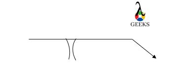
Double flare bevel weld symbol

We already know that different types of welds are represented by different welding symbols. The welding symbol for double flare bevel weld is given below

Double flare
Image: Double flare bevel weld symbol

Note that different types of weld have different symbols which means that different types of bevel welds also have different symbols.

Flare bevel weld vs fillet weld

The comparison between flare bevel weld and fillet weld is given in the section below-

Flare Bevel WeldFillet Weld
There is a cavity inside which the molten metal goes to make a strong bond.There is no cavity required for welding to take place.
No bevelling is requiredNo bevelling is required
A flare bevel weld is made between a flat work piece and a round work piece.A fillet weld is made between two flat plates placed at right anglesTable: Comparison between flare bevel weld and fillet weld

Types of weld

The metal sheets can be joined by using various types of welds. The different types of welds used in the industry are given in the section below-

  • Fillet weld – A fillet weld may sound like a weld having round edges but that is not the case. A fillet weld is triangular in cross section used to weld two plates at right angles.The size of weld is determined by the length of throat size which in turn is calculated using Pythagoras theorem. The length of fillet weld is the total length up to which the weld has been made.
  • Groove weld – Groove weld as the name suggests has a groove within the base metal inside which the molten metal seeps in. The molten metal after cooling forms a strong bond with the base metals. This way the two base metal plates are welded with each other.
  • Spot weld – Spot Welding can be observed by a dot like weld. This is usually done to hold the plates with each other before actual welding is done. The spot weld is made so that when the actual welding needs to be done, the plates will be in tact.
  • Edge welding – Edge welding is done on the edges of the plates. This type of welding seals the plates. The weld is made up till entire length of the edge of the plate. The weld may fail due to shear force acting on the plates.

Conclusion

In this article we have studied about flare bevel weld. The flare bevel weld does not need any type beveling to be done as the work piece themselves have a cavity like shape. The cavity allows the metal to settle in so that it can make strong bond after cooling.

Bevel Weld: What, Diagram, Symbol, Process, Machine, Strength And Several Facts

Bevel

This article discusses about the topic bevel weld. There are many types of welding processes as well as many types of welds that take place after welding.

These types depend on the configuration of metal sheets that need to be welded. In this article we shall discuss about one of many types of welds that is Bevel Weld. First we shall discuss about what is bevel weld, then we shall discuss in brief about other types of welds as well.

What is bevel weld?

A weld that fills the gap between two metals is called as bevel weld. Bevelling is done before we proceed with welding.

Bevelling is the process of removing some metal at the area where weld is going to take place. The weld is made after bevelling process is complete. The weld is formed in the valleys created after bevelling. Let us discuss more about bevel weld in further sections.

Bevel welding symbol

Different types of welds are shown with different symbols. Bevel weld can be represented by the following symbol

Bevel weld size

Size of bevel weld can be determined by measuring effective throat on groove. The size is written on the symbol itself.

The number written inside the parenthesis is the size of the bevel weld. For example if the number written is ¼ (3/8) then the size of weld is 3/8. If there is no number written inside the brackets then the size of weld can not be any lesser than groove depth.  These numbers are written right beside the groove symbol.

Bevel weld angle

Bevel angle is the angle made by the single plate which bevelled. Included angle is the total angle made by preparing both plates.

For a single bevel weld, the bevel angle is equal to the total angle between the plates or the included angle. This is not the case with single-v groove weld. The bevel angle is written between the groove in the bevel weld symbol.

Bevel weld vs fillet weld

The primary difference between both the welds is the configuration of the plates that are welded.

The table below shows the comparison between bevel weld and fillet weld.

Bevel WeldFillet Weld
The bevel weld is made between the plates or work piecesThe fillet weld is made between plates which are placed at right angle to each other
Bevel weld is stronger for same magnitude of force applied.Fillet weld is weaker than bevel weld for same magnitude of force applied.
Table: Comparison between Bevel weld and fillet weld

Bevel weld strength

Strength of the welds is determined by looking at the value of stress under which the weld can fail. There are many types of stresses that can break the weld.

These stresses are mainly tensile stress, compressive stress and bending stress. The weld is weakest for the stress which has the least value. Generally the tensile strength of bevel weld is 0.3 times of the tensile strength of the material used for welding.

Bevel weld process

The bevel weld process includes the following steps

  • Beveling– The sheets are beveled from the ends where the weld needs to be made. Bevelling means removing some material from the end of the plate where the weld needs to be made. Beveling is done so that the molten metal can seep inside the groove and make the bonds properly.
  • Welding– Bevel weld can be made trough many techniques. TIG welding provides the strongest weld.

Types of weld

There are many types of welds made in industry. These welds have different characteristics and are made on the need basis.

The different types of welds are as follows-

  • Fillet welds – Fillet welds are used to weld two plates kept at right angle. This weld is triangular in shape and the size of weld is calculated by measuring the throat length. This can be found using Pythagoras Theorem.
  • Butt weld or Bevel weld – Bevel welds are used to weld plates from its ends. Some material is scraped out so that molten metal can seep inside the valley produced. This way a stronger bond is made.
  • Spot weld – Spot weld is made to join the plates initially such that they do not move. Spot welds are generally made before the actual welding process is started. This is done to keep the plates intact.
  • Edge weld – As the name suggests edge welds are made on the edges of plates. The weld takes place along the length of the edge. This way that side of the plate is sealed by the weld.
  • Slot weld– The slot weld is made by using a hole on the plate. An elongated hole is made to weld two pieces.

Welding defects

No process is perfectly ideal, some defects are bound to be there. The goal is to make as less defects as possible.

Following are the list of defects that can occur in welding.

  • Cracks – Cracks as we all know are sleek openings that happen when the material is stretched more than it can handle. It appears as if the material is torn off. Cracks will propagate if not sealed and it will break the weld if the crack propagates along the entire length.
  • Overlap – This is a welding defect in which the molten metal used for welding runs on the surface of the base metal without actually fusing with it.
  • Porosity – Porous means something which has pores and gases can pass through it. Porosity in welding means that the weld is left with some pores through which gases enter inside the weld making the weld weaker. For example Oxygen can corrode the metal.
  • Undercut – In this defect, the thickness of weld metal is reduced due to which its strength is compromised.
  • Slag inclusion – Slags are tiny particles that are non metallic. Slag act as impurities in the weld, because of slag inclusion the weld strength will be compromised.
  • Incomplete fusion- Incomplete fusion means the weld metal has not completely bonded with the base metal. This can happen due to lower temperature while welding or insufficient current in the circuit.
  • Incomplete penetration – Incomplete penetration happens in groove welds when the weld metal does not penetrate through the entire joint thickness.

Summary

In this article we studied in detail about bevel welds. We realised that beveling makes it easier for the molten metal to seep inside. This makes the bond stronger. The molten metal sits perfectly inside the cavity which when cooled makes a good joint between the plates.

SMAW Welding: What, How,Symbol, Diagram, Process, Parts,Electrodes

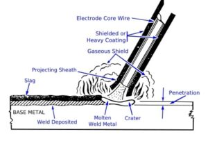
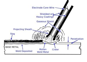
450px SMAW weld area.svg 300x213 1

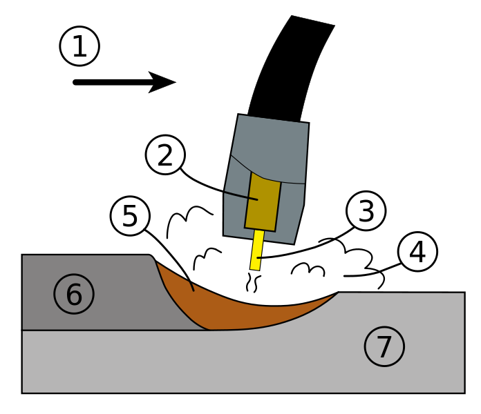
This article discusses about the topic SMAW welding. SMAW stands for Submerged Metal Arc Welding. The name of this type of welding gives us an idea that the metal electrodes is submerged in some kind of fluid.

SMAW employs a consumable electrode which has a protective coating on it. When the electrode starts melting, the coat starts wearing off and then protects the weld pool oxygen and other atmospheric gases. In this article we shall discuss about SMAW in detail.

What is SMAW welding?

SMAW or Submerged Metal Arc Welding is a process in which the electrode itself has a coating which melts and protects the weld pool from contaminating gases like oxygen and other atmospheric gases.

An electric arc will be forming between the tip of the electrode and the surface of work piece. The electric arc is formed when the electrode is touched and electric current is passed through it. The arc forms as soon as the electrode is lifted by some distance. Due to the electric arc, excess heat is generated which melts the electrode and the coating on it.

SMAW welding process

SMAW welding process is a type of welding in which the coalescence of metals takes place by the heat generated from the electric arc generated between the electrode and the surface of the work piece.

When an alternating current or direct current is applied on the electrode, an electric arc is formed between the electrode and work piece. The electric arc is formed when the electrode is lifted by a small distance from the work piece. The electric arc produces enough heat that can be used for welding two metal pieces.

SMAW welding diagram

The welding diagram of SMAW process is shown below-

smaw welding
Image: SMAW welding diagram

Image credits: Wikipedia

SMAW weld symbol

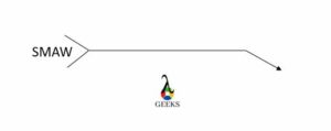
There are many types of symbols which represent different types of welds. The SMAW is represented by the following symbol-

Capture 3
Image: SMAW Welding symbol

SMAW welding machine

An SMAW welding machine is an assembly of certain equipment used to perform SMAW welding process. The machine requires a consumable electrode and electric supply.

The major equipment is the power source of SMAW process that may include- welding transformer, a dc rectifier or a dc generator set. A consumable electrode is used which has protective coating which melts when heat is produced on the weld area. When the coat melts, it provides shielding to weld pool from gases like oxygen and other impurities.

SMAW welding temperature

The SMAW welding process requires the electrode to reach a particular temperature to melt and for welding to take place. The electric arc will be generating the heat.  

On an average the SMAW process requires around 11,000 Degrees Fahrenheit or 6100 Degrees Celsius for the welding to take place. The temperature depends on the magnitude of electric current passed through the electrode.

SMAW welding electrodes

In industry there are four common types of electrodes used for welding. They are flat, horizontal, vertical and overhead.

These are further named depending on the material properties. In SMAW process electrodes named 6010, 6011, 6013, 7018 and 7024 are used. Their diameters range from 1/8 to 5/32 inches. These electrodes can work in all the positions except 7024.

SMAW welding technique

The SMAW welding process can be started by two techniques. They are listed below-

  • Scratch start technique– The name tells us that scratching of two things is taking place which in this case is electrode and work piece. The electrode will light up when an optimum distance between the work piece and electrode is made.
  • Tapping technique– As the name suggests, the electrode is tapped on the surface of the work piece. When an optimum distance is achieved between electrode and work piece, an electric is produced between workpiece and electrode.

SMAW welding circuit

The SMAW welding circuit includes the following parts-

  • Power source- It provides the necessary voltage difference to create the electric arc between the  work piece and the electrode.
  • Welding cables- The welding cables hold the electrode as well as provide current to the electrode.
  • Electrode holder- As the name suggests it holds the electrode firmly.
  • Ground clamp- Ground clamp fixed the work piece tightly so that it does not move while welding is taking place.
  • Base metal- The base metal is the metal on which welding is going to take place.
  • Arc welding electrode– Arc welding electrode is the electrode having a coating on it which shields the weld pool after melting.

SMAW advantages and disadvantages

The advantages and disadvantages of SMAW welding process are given in the section given below-

Advantages

  • The equipment cost is lower than other conventional methods of welding.
  • Change from one material to another is easy.
  • Deposition rates are faster in SMAW
  • The apparatus is easy to shift from one place to another.
  • There is no need of shielding gas.

Disadvantages

  • The deposition rate is still lower than GMAW
  • The cost of filler metal per length is higher
  • It needs more hand eye coordination
  • The slug must be removed
  • Production speed is lower

How to calculate travel speed in SMAW welding?

Welding speed is important to calculate so that we can know the time it will take to complete the welding procedure. The travel speed in SMAW welding can be calculated by the following formula-

Travel speed= Length of weld/ Time to weld

The units of travel speed are mm /s, inches /sec or cm /s.

Why is SMAW good for welding outdoors?

No special gas is required for shielding in SMAW welding process. The equipment used in SMAW process can be moved from one place to another.

The slug can be removed by light and medium winds. The weld area can be cleaned by the wind blowing outside. Hence it is recommended to perform the SMAW welding process outdoors.

SMAW welding vs TIG welding

The table below shows the comparison between smaw and tig welding

SMAW WeldingTIG Welding
The smaw process uses a consumable electrodeA non consumable electrode is used in this process.
The electrode is non reusableThe same electrode can be used again for another round.
Table: Comparison Between SMAW Welding and TIG Welding

SMAW welding vs GMAW

The table below shows the comparison between smaw and gmaw

SMAW WeldingGMAW Welding
The electrode used in the smaw process cannot be reused and it is consumableThe electrode used in the gmaw process is also consumable and cannot be reused like in SMAW process
The machine needs to be stopped to change the electrode.The machine need not be stopped because the electrode is automatically fed to the system by the spool
Table: Comparison between SMAW Welding and GMAW Welding

SMAW welding vs fcaw

The table below shows the comparison between smaw and fcaw welding process

SMAW WeldingFCAW Welding
The electrode used in the smaw process is covered with an inert gas used for shieldingThe flux will be filled only at the core of electrode. Unlike the electrode used in SMAW process.
Electrode used in this process is consumable.The electrode used is consumable like in smaw.
Table: Comparison between SMAW Welding and FCAW welding

SMAW vs Gtaw welding

The table below shows the comparison between smaw and gtaw welding

SMAW WeldingGTAW Welding
The electrode is consumableThe electrode is non consumable and re usable
The electrode has inert gas coating which keeps meltingThe shielding gas is fed externally from the cylinder
Table: Comparison between SMAW Welding and GTAW Welding

Summary

We have discussed about SMAW welding process in this article. We also discussed about various other welding processes. We saw that SMAW welding requires a consumable electrode which has a coating that on melting protects the weld pool from harmful gases. Gases can penetrate inside weld pool and affect the strength of weld.

Surfacing Weld: What, Diagram, Symbol, Process, Machine, Strength and Several Facts

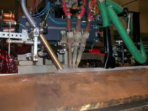
800px Submerged Arc Welding 2 300x225 1

In this article, concerned giving information on “surfacing weld” will be discussed. By the surfacing weld the properties such as friction, abrasion, and resistance are improved in a metal or alloy.

By the help of surfacing weld the properties of chemical and physical can be improved of a material. Surfacing weld is performed by spray or weld a filler metal which is coated to a matter. Corrosion is prevented of a matter by the surfacing welding.

What is a surfacing weld?

Surfacing weld is not expensive method it is economical to extending and conserving the life of construction equipment, tools and machines.

Surfacing weld can be explain as, a weld which is applied to a surface, like that prevents to a make a joint, for getting aimed dimensions or properties. Surfacing is a welding method which is used a wear resistant, hard covering of metal to borders or grounds of worn out sections.

In various industrial fields surfacing weld is widely used. The industrial fields are listed below,

  1. Farming industrial fields
  2. Coal industrial fields and Mining industrial fields
  3. Chemical sector industrial fields
  4. Manufacturing industrial fields
  5. Petrochemical industrial fields
  6. Shipbuilding industrial fields
  7. Structural industrial fields and construction industrial fields
  8. Shipyard industrial fields

Surfacing weld symbol:

The symbol of the surfacing weld should be clearly indicated to the area where the deposition of surface welding is happened.

The symbol of the surfacing weld is used to pointed,

  • Cladding for corrosion resistance
  • Hard facing with wear resistance material
  • Build – up surfaces to required dimensions.

Thickness for the weld of the surface is indicated clearly by installing the dimension to the left flank of the symbol of the weld, the placed which is surfaced is pointed on the sketch.

Surfacing weld symbol can be determined with the help of some steps. The steps are listed below,

  • Determine the classification of the joint and preparation of the joined is required
  • Visualize the opening of the root
  • Visualize the angle of the groove
  • Visualize the radii of the root and also the face dimension of the root
  • Visualize the thickness of the groove
  • Visualize the size of the weld
  • Visualize the contour finish
  • Visualize the finishing process
  • Visualize the edge of the joint

Determine the classification of the joint and preparation of the joined is required:-

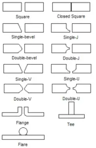
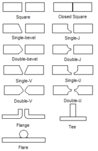
The AWS A2.4:2007 is introduced by the American Welding Society they are published the symbol for the process of welding which contain different classifications of joints of groove which can be double or single. Single groove means joint by only one side and double groove means joint by both side. The symbols of the welding for the different types of joints of groove are listed below,

  • Bevel groove
  • V groove
  • Scarf
  • Square groove
  • U groove
  • J groove
  • Flare V groove
  • Flare bevel groove

Visualize the opening of the root:-

The opening of root will be indicating within the sign of the groove type. Root opening actually the amount of the detachment by the two pieces of the base metal. If detachment is not present showing that’s mean no space is present in by the parts. 0 is also admissible for the sign of the root opening.

Visualize the angle of the groove:-

The groove angle is expressed as degree. The angle of the groove can be present in the above section or the below section of the dimension of the root. The presences of groove angle depend upon the arrow.

Visualize the radii of the root and also the face dimension of the root:-

In the two ways, the radii of the root and also the face dimension of the root can be determined. The ways are listed below,

With the help of the drawing of cross section the dimension for the root opening is shown.

Need to note down the tail for the symbol of the welding process.

Visualize the thickness of the groove:-

The thickness of the preparation of the grooves is shown in the side of the left of groove weld symbol.

Visualize the size of the weld:-

In a groove weld, weld size is the effective throat. The weld size is included the penetration rate of the root of the groove and also the depth of the groove. The weld size will be display the left side of the symbol of the groove in parenthesis. If number is absent in the parenthesis then weld size not be lower than the depth of the groove.

Visualize the contour finish:-

The contour finish for the fillet weld can be classified in three categorized, such as,

  • Flat contour finish
  • Concave contour finish
  • Convex contour finish

Visualize the finishing process:-

The symbol of the welding describes how much contour can be achieved. As a example, a flat contour by the grinding process the requirement is, AWS A2.4:2007 is introduced by the American Welding Society standard symbol for Brazing, Non-destructive investigation identified methods of finishing with 7th unspecified method,

  • C – Chipping
  • G – Grinding
  • H – Hammering
  • M – Machining
  • P – Planishing
  • R – Rolling
  • U – Unspecified

Visualize the edge of the joint to be produce when the picture demands for a single bevel:-

In the case for the J groove, flare bevel and bevel symbol of welding inform us which side need to produce by having an arrow which is broken. When we observe the arrow which is already broken that’s mean the particular the side of the weld need to prepared.

Surfacing weld size:

The surfacing weld size can be estimated by the help of height of the weld from the substrate to the surface of the weld. The direction of the weld of surfacing welds is pointed in the tail of the symbol of the welding by the denominations of circumferential, axial, lateral, procedure of the welding and longitudinal.

Methods uses during the Surfacing weld joint:

The methods are uses during the Surfacing weld joint are listed below,

  1. Furnace fusing
  2. Plasma Arc Welding Surfacing
  3. Gas Metal Arc Welding Surfacing
  4. Gas Tungsten Arc Welding Surfacing
  5. Submerged Metal Arc Welding Surfacing
  6. Submerged Arc Welding Surfacing
  7. Oxy Acetylene Surface welding
  8. Flux Cored Arc Welding Surfacing
surfacing weld
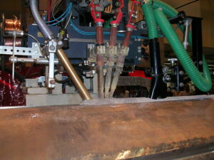
Image – Submerged arc welding. The welding head moves from right to left. The flux powder is supplied by the hopper on the left hand side, then follow three filler wire torches and finally a vacuum cleaner;
Image Credit – Wikipedia

Avoid things to prepare Surfacing weld design:

Thoughtless the method of cleaning, there are lots of vital things to avoid when the surface weld design is done. The things we have to avoid while prepare the design of surface welding,

  1. Leaving the marks or deep grooves
  2. Cutting excess amount of the plane of the workpiece
  3. During the wet metal welding is done
  4. Forget to wipe down the metal before starting
  5. Not properly handling the chemicals

Leaving the marks or deep grooves:-

When the marks or deep grooves are leave in that case the containments driven into the grooves and the process of surface welding became very difficult to perform.

Cutting excess amount of the plane of the workpiece:-

When surface welding perform with very thin metal or metal sheet in that case if excess amount of surface is cut down from the workpiece then the strength of the metal also the shape of the metal get effected.

During the wet metal welding is done:-

In the surface welding the methods which are widely used is, Tungsten Insert Gas Welding and Metal Insert Gas Welding. The welding method Tungsten Insert Gas Welding and Metal Insert Gas Welding always should to perform when the metal is completely dry.

Tungsten Insert Gas Welding and Metal Insert Gas Welding method never should to perform during the wet metal.

Forget to wipe down the metal before starting:-

In naked eye the metal can be looks like so clean but invisible impurities can be still present in the metal. So, before beginning the surface welding process the metal always should to wipe down to avoid type of disturbance.

Not properly handling the chemicals:-

In the surface welding process chemicals are use to run the process for avoiding any type of chemical reaction we should wear proper gloves, goggles and need to wash up solvents properly when it is done.

Frequent Asked Question:-

Question: – Describe about the different types of Surfacing in welding.

Answer:-The classification of Surfacing in welding are listed below,

  • Hardfacing
  • Buttering
  • Buildup
  • Weld Cladding

Hardfacing:-

By the help of hardfacing the properties for the base metals are improved. The properties which are improved are resistance, strength and durability. Hardfacing can be explaining as, a stronger material is credited to a workpiece.

Buttering:-

Buttering can be explaining as, a metal with dissimilar properties is credited to a workpiece.

As an example, in alloy of steel nickel alloy is credited

Buildup:-

When a base metal is added to a junction, prior weld or surface, this type of surfacing weld is known as buildup.

Weld Cladding:-

Weld Cladding can be explaining as, when corrosion resistant material is credited into the workpiece.

Conclusions:-

  • The surfacing welding is dine in a base metal to protect from corrosion.
  • The initial cost is lower comparative than the others welding methods.
  • Maintained cost is also low.
  • Skilled worker not needed to perform the surface welding.

Laser Welding Vs Welding : Comparative Analysis On Different Features

SMAW 200x300 1

This article discusses about laser welding vs welding. Welding here refers to different types of welding processes used in industry. Welding can be defined as the process of joining two or more metals.

They can be similar or dissimilar. Depending upon the applications, welding can be classified into many types. Sometimes even a weak weld can do the job whereas some times the weld needs to have a lot of strength. This article will compare laser welding with other types of welding.

What is laser welding?

In the name itself, it suggests that laser welding uses lasers for welding purpose. Lasers provide a very narrow and concentrated heat source.

Narrow and concentrated heat source will make room for deeper welds and higher welding rates. This type of welding can be used in automation where high volume production of the same product needs to be done. In industries mostly the robots do the laser welding.

Types of welding

There are many types of welding. The type of welding depends on the source of heat, type of electrodes used, method of heating the desired area and much more.

The types of welding are discussed in the section given below-

  • Gas welding – Gas welding uses a gas to produce flame hence the name gas welding. The major advantage of using gas welding is that we can control the temperature of the weld zone by changing the temperature of the flame which is done by regulating the flow of gas.
  • Solid state welding – No filler metal is used in this process. Coalescence is produced at temperatures below the melting point of the base materials that are being welded.
  • Resistance welding – Electrical resistance is used to generate heat for welding purposes. The electric current is passed through the metals that need to be welded. The resistance created in this process generates enough heat to weld the metals.
  • Arc welding – An electric arc is generated between the work piece and an electrode. This electrode generates enough arc to produce heat for welding.
  • Newer welding– Rapidly moving objects create heat through friction which is used for welding purposes.

Laser welding vs arc welding

The table below shows the comparison of laser welding and arc welding

Laser Welding Arc Welding
Cleaner welds are provided by this type of welding Soot is produced from the burnt electrodes.
More precise welds The precision of welds depends on the operator
Easy to automate It is semi automatic or manually operated.
Can be used on thinner materials as well Used on thin materials but does not provide enough strength
The welds have high tensile and bending strength. Provides lesser tensile and bending strength.
Table: Comparison between Laser Welding and Arc Welding
laser welding vs welding
Image: Shielded Metal Arc Welding

Image Credits: WeldscientistExcalibur 7018CC BY-SA 4.0

Laser welding and TIG welding

The table below show the comparison between laser beam welding and tig welding. TIG stands for Tungsten Inert Gas.

Laser Welding TIG Welding
The welds are precise The precision depends on the workers
The welds are cleaner The welds are not as clean as laser welds
Laser beam welding uses lasers for welding In TIG welding, lasers are not used for welding
No electrode is used Tungsten electrode is used for welding
Easy to automate Even TIG welding can be automated easily.
Table: Laser Welding Vs TIG Welding

Laser welding vs MIG welding

MIG stands for Metal Inert Gas. The table below shows the comparison between laser welding and mig welding.

Laser Welding MIG Welding
Uses high precision laser beam for welding Uses metal electrodes for welding purposes.
Deep penetrations using laser provide better welding strength to thick plates. The penetration power of mig is not as good as Laser welding
No inert gas is used An inert gas shields the weld pool
No electrode is used in this process A metal electrode is used in this process
Sheets having large thickness can be welded in a single pass only. Thicker sheets can be welded using MIG but it will need more number of passes to complete the job.
Table: Comparison between Laser Welding and MIG Welding

Electron beam welding vs laser welding

Both of these welding techniques are modern and are expensive in nature. Both of them have similar weld characteristics.

The table below shows the comparison between electron beam welding and laser welding-

Laser Welding Electron Beam Welding
Uses a monochromatic beam of light or laser for welding purposes Uses a beam of fast moving electrons for welding purposes.
The penetration power is high The penetration power is high
Deeper penetrations provide strength to thicker welds. Deeper penetrations provide strength to thicker welds.
No electron beam is used for welding purpose Electron beam is converged using a converging apparatus
Cleaner welds The welds are cleaner compared to other conventional methods of welding
Table: Comparison between Laser welding and Electron beam welding

Laser welding vs Ultrasonic welding

The table below shows the comparison between laser welding and ultrasonic welding

Laser Welding Ultrasonic Welding
Uses a monochromatic beam of light for welding purposes Uses vibrating electrode for welding purposes
The rate at which material is removed is high Material removal rate is lower than laser welding
This process allows to penetrate deep in to the metals for welding Penetration power is low so multiple passes are required to weld thicker plates
No electrode is used for welding purposes No electrode is used in this type either
The weld strength is high The strength of weld using ultrasonic welding is lower than the weld strength provided by laser welding
Laser welds can withstand higher amount of currents. The amount of current that it can withstand is lesser
Table: Comparison Between Laser Welding and Ultrasonic Welding

Spot welding vs laser welding

Spot welding as the name suggests contains a weld in the form of small bead or dot. The table below shows the comparison between spot welding and laser welding

Laser Welding Spot Welding
It uses a beam of laser to weld. Uses a metal strip and electrode for welding purposes
The welding takes place at a faster rate than resistance spot welding The process is slower than laser welding
Better weld quality The quality of weld is not like laser welding it is slightly lower in quality.
Repeatability is also better of laser weldingRepeatability is not like that of laser weldingCannot be used for every jobIt can weld sheets of metals which are thinTable : Comparison between Laser welding and Spot welding

Laser welding vs plasma welding

The table below shows comparison between laser welding and plasma welding.

Laser Welding Plasma Welding
A laser beam of high intensity is used to generate heat in the area that needs to be weld. It uses a high density plasma arc beam as the heat source to weld the metal sheets
It can be compared to MIG welding to produce hybrid welds. It can alone be used to produce high density welds with low stress concentration
High penetration ability It also has a high penetration ability
Inert gas is required Inert gas is used to shield the weld pool
No special environment is needed Special environment is required
Table: Comparison between laser welding and plasma welding

Laser welding vs resistance welding

The table below shows the comparison between laser welding and resistance welding –

Laser Welding Resistance Welding
Produces only fusion weld Produces three types of weld- solid state, fusion and braze
External weld is produced by this type of process An internal weld can be produced by using resistance welding.
The welding procedure employs a high intensity laser beam The welding procedure employs the heat generated by electrical resistance between the metal sheets when electric current is applied to them.
High penetration The penetration is not that deep as compared to laser welding
Table: Comparison between Laser welding and Resistance welding

Summary

In this article we compared laser welding with other welding techniques. We could see clearly that laser welding has majorly an upper hand over other welding techniques due to its high penetration power and ability to generate high amount of heat at a single spot.

Single Bevel Weld: What, Symbol, Diagram, Process, Machine, Strength And Several Facts

Bevel and chamfer.svg

In this article, the subject ,”single bevel weld” with  single bevel weld respected facts such as, Symbol, Diagram, Process, Machine, Strength will be summarize in a brief manner.

In a butt weld or a groove weld the components are related to each other in a same surface. The butt weld and groove weld represent the same type of the weld. American National Standards Institute represents the term groove weld and International Organization Standardization represents the term of butt weld.

What is a single bevel weld?

Angle of bevel is only one half of the weld of V groove. The dimension for the bevel weld only shown within the symbol of the weld itself.

A single bevel weld can be explain as, a groove weld that’s one part has a junction edge beveled from one side. The parts consists by the single bevel weld are, Root face, Groove angle, Root gap and Bevel angle.

Single bevel weld symbol:

Single bevel weld symbol can be determined with the help of some steps. The steps are listed below,

Determine the classification of the joint and preparation of the joined is required:-

The AWS A2.4:2007 is introduced by the American Welding Society they are published the symbol for the process of welding which contain different classifications of joints of groove which can be double or single. Single groove means joint by only one side and double groove means joint by both side. The symbols of the welding for the different types of joints of groove are listed below,

  1. Bevel groove
  2. V groove
  3. Scarf
  4. Square groove
  5. U groove
  6. J groove
  7. Flare V groove
  8. Flare bevel groove

Visualize the opening of the root:-

The opening of root will be indicating within the sign of the groove type. Root opening actually the amount of the detachment by the two pieces of the base metal. If detachment is not present showing that’s mean no space is present in by the parts. 0 is also admissible for the sign of the root opening.

Visualize the angle of the groove:-

The groove angle is expressed as degree. The angle of the groove can be present in the above section or the below section of the dimension of the root. The presences of groove angle depend upon the arrow.

Visualize the radii of the root and also the face dimension of the root:-

In the two ways, the radii of the root and also the face dimension of the root can be determined. The ways are listed below,

With the help of the drawing of cross section the dimension for the root opening is shown.

Need to note down the tail for the symbol of the welding process.

Visualize the thickness of the groove:-

The thickness of the preparation of the grooves is shown in the side of the left of groove weld symbol.

Visualize the size of the weld:-

In a groove weld, weld size is the effective throat. The weld size is included the penetration rate of the root of the groove and also the depth of the groove. The weld size will be display the left side of the symbol of the groove in parenthesis. If number is absent in the parenthesis then weld size not be lower than the depth of the groove. 

Visualize the contour finish:-

The contour finish for the fillet weld can be classified in three categorized, such as,

  • Flat contour finish
  • Concave contour finish
  • Convex contour finish

Visualize the finishing process:-

The symbol of the welding describes how much contour can be achieved. As a example, a flat contour by the grinding process the requirement is, AWS A2.4:2007 is introduced by the American Welding Society standard symbol for Brazing, Non-destructive investigation identified methods of finishing with 7th unspecified method,

  • C – Chipping
  • G – Grinding
  • H – Hammering
  • M – Machining
  • P – Planishing
  • R – Rolling
  • U – Unspecified

Visualize the edge of the joint to be produce when the picture demands for a single bevel:-

In the case for the J groove, flare bevel and bevel symbol of welding inform us which side need to produce by having an arrow which is broken. When we observe the arrow which is already broken that’s mean the particular the side of the weld need to prepared.

Single bevel weld size:

The size for the single bevel is included the penetration rate into the root of the groove weld and also depth of the groove. In the side of the left the size for the single bevel weld will be shown of the symbol of the single bevel weld in parenthesis.

If any number is not contain by the parenthesis then obviously the size of the single bevel weld surely is not less than the depth of the groove of single bevel weld.

Single bevel weld joint method:

A bevel shape weld means the structure of the edge is not perpendicular across the faces of the parts. The words chamfer and bevel overlap in usage.

The single bevel weld joint can be making stronger using the method name is, Tungsten Insert Gas Welding. Another name for the Tungsten Insert Gas Welding is, Gas Tungsten Arc Welding. With help of Tungsten Insert Gas Welding also cleaner weld can be making. The weld is produced by heating with an arc between a single tungsten (non consumable) electrode and the work.

GTAW helps prevent distortion, particularly on thin materials. Overall, the lower heat generated by the GTAW process also minimizes the chances of burn-through on thin materials.

Shielding is obtained from an inert gas mixture. No weld spatter or slag is produced.

In the general uses of the chamfer and bevel they are frequently permutation. Even though some usage of technical purpose the chamfer and bevel can be differentiated sometimes.

The other method are to shape a single bevel weld joint are listed below,

  1. Metal Insert Gas Welding
  2. Flux Cored Arc welding
  3. Submerged Arc Welding 
  4. Shield Metal Arc Welding

Single bevel weld design advantages and disadvantages:

The advantages and disadvantages of the single bevel weld design is listed below,

Advantages:-

  • Leak proof joining
  • Joining of the different shapes
  • Metals which are dissimilar are jointed
  • Strength of the joint is superior
  • High load capacity
  • Joining of plastics
  • Light welded assemblies
  • Changing of the mechanical properties

Disadvantages:-

  • Skilled welders are needed to perform the single bevel weld design.
  • Electricity required.
  • Joints of the single bevel weld design are brittle type for this reason the fatigue strength will be less comparative to the member joints.
  • The inspection for the single bevel weld design is more complicated.
  • Defects such as, incomplete penetration, slag inclusion, air pocket, are very complicated to detect.

How to measure a single bevel weld?

The formula is used to measure a single bevel weld is listed below,

P = WLE

Where,

 P is represented as, Pounds of wire or electrode is required in the single bevel weld.

W = Weight of the weld metal in per foot.

L = Length of the weld which is expressed as, feet

E = Deposition efficiency

The fillet weld size can be estimated with the help of leg length. The fillet weld size determine as, an equilateral triangle. An original weld never can be triangle and the shape will be convex or concave and not required to equal the lengths of the legs.

Frequent Asked Question:-

Question: – What are the advantages using the bevel weld?

Solution: – The advantages of using the bevel weld is listed below,

The J bevel is that the boundary layers are stay more uniform through a larger portion of a tube and less material is used to fill the space.

Less amount of welding is involved for this particular reason heat affected zone is smaller in size.

single bevel weld
Image – Side views of a bevel (above) and a chamfer (below);
Image Credit – Wikipedia

Question: – What is easiest welding process.

Solution: – The easiest welding process is Metal Insert Arc welding process.

In the Metal Insert Arc Welding method the electric arc is produce in between a workpiece metal and consumable wire electrode.

Metal Insert Arc Welding is most used in source of direct current power, constant voltage. The Metal Insert Arc welding method also used in alternating current and constant current.

Metal Insert Arc Welding process inert gases or mixture of gases as the shielding gas. Helium and Argon mixes are inert gases and non ferrous metals are used. In the Metal Insert Arc Welding method high skilled operators are not needed to operate.

696px GMAW weld area.svg
Image – Metal Insert Arc welding process weld area:
(1) Direction of travel, (2) Contact tube, (3) Electrode, (4) Shielding gas, (5) Molten weld metal, (6) Solidified weld metal, (7) Workpiece;
Image Credit – Wikipedia

Conclusion:

Single V welds is almost similar to the bevel joint. In the single v welds only one side have beveled edge and in the bevel joint both of the sides have beveled edge.

Butt Welding: What, Diagram, Symbol, Process, Machine, Strength And Several Facts

220px Butt Weld Geometry 2 196x300 1

Butt Welding is a frequently used technique in welding industries, both automated and manual methods of butt welding are very popular from decades.

A butt weld joins two metal surfaces lying edge to edge on the same plane against one another. In case of a gap in between the plates, the maximum allowable gap is 1/16 inch and finally, this gap is filled with a welding rod during the welding process.

Mainly Butt and Fillet welds are the two types of continuous welds, all other joints are the modification of these two types.

butt welding
Single V butt Weld; Image Credit: wikipedia

What is a Butt Weld?

Butt Weld is the most familiar, simplest and versatile form of joint used in fabrication industries and pipelines.

In Butt Weld, the two members do not overlap each other and their edges are nearly parallel to each other. Butt weld joint is done simply by placing two metal plates or components side by side on the same plane and weld metals remain along the joint, within the planes of the surfaces.

This method of welding is very common in industries like piping, automobile, energy, power etc.

Butt Joint Diagram

Butt Joints are widely used in fabrication industries and pipelines. Molten metal is applied in the outer circumference of the joint.

Different types of Butt welds are prepared depending on the thickness of the metal plates, groove and edge preparation are necessary before welding. In the figure below different types of Butt welds are shown, which will give a clear idea.

220px Butt Weld Geometry 2
Butt Joint Geometries; Image Credit: Wikipedia

Butt Weld Symbol

Standard symbols are used within a drawing to guide the welders which in turn helps to get a better control over finished appearance and mechanical properties of welds.

The US standard symbols are outlined by the American National Standards Institute and the American Welding Society and are noted as “ANSI/AWS”. Welding symbols are most widely used in metal fabrication drawings.

Welding symbols are most widely used in metal fabrication drawings.

Butt Weld can be symbolized with the help of
1. An arrow line
2. A reference line
3. A dashed line
4. A symbol

The technical drawings for welds consist of an arrow, the arrow head always points towards the joint to be welded. This arrow comprises with letters, certain symbols and numbers which indicates design or pattern of the weld joint.

440px Fillet Weld Notation 1
The symbolic representation of a V weld of chamfered plates in a technical drawing; Image Credit: Wikipedia

Butt Welding Process

Generally to butt joints are welded adopting methods like arc welding, resistance welding, high energy beam welding and even it is done by brazing for copper pieces.

MIG or TIG are mostly applied for Butt Welds as they can naturally join two pieces of metal together, different types of welding electrodes are used to enhances properties like corrosion resistance and strength.

The area which is melted during welding process is known as the faying surface, to increase the strength of the weld, the faying surface has to be shaped which is popularly known as edge preparation. Edge preparation is compulsory in most of the butt joint designs.

Edge preparation may be same or different for both the members of butt joint.

Butt Joint Uses

Simple, strong, durable, wide range of material coverage, smooth surface finish etc are the pros which make a butt weld more versatile.

One of the most common type of weld joints and observed in fabrication works and pipeline in industries. Butt joints are also used in automotive sectors, manual arc welding applications, power and energy sectors.

Butt Joint Advantages

Butt welds are preferred over another types of weld as it creates a strong weld and can be applied for various situations.

The advantages offer by Butt Welds are as follows:

  • Butt welds can be performed over a wide range of materials like aluminum, steel, stainless steel, nickel alloys, titanium etc.
  • It gives a strong and permanently sealed joint with complete fusion.
  • We can get low cost pipe fittings with these welds.
  • The welds have a smooth surface finish as the filler metal is deposited into the groove.
  • Occupy a small space in a structure.
  • It is possible to create multiple welds of different shape and size over the joint area.
  • Inspection of butt welds is quite easy.
  • Machining is simple and
  • It provides distortion control.
  • Less prone to dirt and pollutions.

Butt Joint Disadvantages

The advantages associated with Butt Joint are as follows:

  • In case of thick metals, beveling of the joint edges is required for Butt welding.
  • Burnthrough, Porosity, cracking and incomplete penetration are associated with these joints.
  • Due to the welding geometry, applications can be limited.
  • Due to the geometry of the welds, restrictions come in their applications.
  • Difficult to weld thin sheet metal piece without filler metal.
  • Sensitive towards faying surface conditions.

Types of Butt Joints

Butt Joints are made in different designs depending on width of the gap, thickness of the plates and they are used for different purposes.

Certain typical examples of Butt Joints are listed below:

Square butt weld

This one is the simplest joint design, the thickness of metal pieces to be joined are 3/16 inch or less than that. On thin metal piece, a full penetration welds can be possible using square butt welds.

Though the square butt welds are quite strong they are not suitable for constant fatigue loads. The edges of two pieces do not need any modifications like beveling or chamfering.

Single and double Bevel Butt Weld

In case of thick metal pieces, it is difficult to get 100% penetration using butt welding, for this purposes certain type of groove preparation is required.

 In single bevel design one piece remains as square and the other part is beveled to a specified angle.

Single and Double V Butt Weld

V welds cost more in preparation than square butt welds, it also consumes more filler material. Using cutting torch or beveling machine, the V groove is prepared. The main advantage is that V welds are stronger than square butt joint

The preparation time for double V is longer in comparison to single V. But use of filler metal is less as double V gives a narrower space.

Single and Double  U butt weld

The preparation and welding cost of the U joint is the highest. The two pieces are prepared as a J groove and when they come together it gives a shapethe oa f U.

In double U joint , U shaped groove exists both on top and bottom of the joint, generally applied on thick base metals.

Single and double J Butt Weld

J groove is more difficult and costly to prepare than V groove, groove preparation is done by special machinery or grinding. Here one member is in J shape and the other one is square.

In double J, one piece is in J shape from both the ends and the other one is in square shape.

Mitered Butt Joint

The classic example of a mitered butt joint is a painting frame, consisting of four butt joints at each corner, all the four ends cut at a 45 degree angle.

A mitered butt joint is an union between two pieces cut at 45 degree at the corner and place next to one another  to usually form an angle of 90 degree. It can and do vary at any angle greater than 0 degree and the joint meets at a sharp point. Picture frame, molding and pipes are the common examples.

330px Mitre joint pipe
Mitered Joint of two pipes; Image Credit: Wikipedia.

It is a kind of easy wood working joint which generally gives a pretty look in picture and painting frames. They are not strong enough since they have no interlocking elements and depend only on wood glue.

Upset Butt Welding

Upset or Resistance Butt Welding is mainly used for nonferrous materials of smaller cross-sections like bars, rods, tubes, wires, etc.

This type of welding produces coalescence simultaneously along the joint, by the heat generated from electrical resistance through the area where the surfaces are in contact. Application of pressure is mandatory , heat application starts prior to heating and goes all throughout the process.

Upset welding is also observed in steel rails, closure of capsules, small containers etc.

Square butt weld

This one is the simplest joint design, the thickness of metal pieces to be joined are 3/16 inch or less than that.

Though the square butt welds are quite strong they are not suitable for constant fatigue loads. The edges of two pieces do not need any modifications like beveling or chamfering. On thin metal piece, a full penetration welds can be possible using square butt welds.

Butt vs Fillet Weld

Both of them are the most common continuous welds.

We can differentiate between Butt and Fillet welds as mentioned below:

ButtFillet
The members to be welded are lying on the same level.If the joining surfaces are perpendicular to each other, then they are joined with fillet welds.
Edge preparation is must in case of butt weldsDo not require any kind of edge preparation.
The joining surfaces are placed side by side or edge to edge.Lap joint is also a type of fillet welds where two surfaces overlap each other.
Look wise weld can be resemble with seam or bead.A 45 degree angle is formed between the two parts in case of fillet welds, filler metal is deposited in a triangular section at the joint.

Butt weld vs Socket weld

Both Socket and Butt weld are quite popular.

We can differentiate between Butt and Socket welds as mentioned below:

ButtSocket
Here two pieces of pipes are kept in same plane and then welded.In case of Socket weld two different diameter’s pipes are used and smaller one is inserted into the larger one.
For better penetration beveling is required.Both the ends are square cut and no need of beveling or any preparation, other than surface cleaning.
Generally used for pipes having large diameters.Mostly applied for small diameter pipes.
Pipes are connected by butt welding.It gives a fillet weld.
X-ray inspection method is adopted for testing.Non destructive testing methods  like magnetic powder testing(MT) or Penetration Testing(PT)are adopted.
Highly resistant to corrosion.Less corrosive resisteant.

If we consider a small diameter pipe the cost of socket weld fitting is higher than butt weld fittings but butt welds are more expensive if we consider design, testing ,installation and maintenance. Socket joints are quite easy in terms of assembly, maintenance and installation making it less expensive than but welds.

In certain conditions Butt welds prove almost twice as much as stronger than socket welds.

.

Butt Welding Machine

An efficient Butt Joint machine should provide accurate welding pressure as well as a strong welding strength.

A Butt welding machine must possess a body with clamps, trimmer, heater, a removable electric facer, control unit, machine housing box and a set of inserts to adjust with different diameters of pipes.

The price of the welding machine varies as per the welding diameter of the product, for large weld diameter the cost of the welding machine is also high.

These machines vary in size between W160(power 220V -.55 KW) -W2800(power 380V -4KW).

Conclusion:

To wrap up our post we can state that Butt Welding is one of the most widely used welding process which results different types of Butt Welds with different specialties and they have to be selected carefully as per our requirement and budget.