What is comparator circuit ?
A comparator or a voltage comparator is a device used to compare two voltage levels. We can determine which voltage level is higher from the comparator’s output. It is an application of typical op-amps, and it has applications furthermore.
What does a comparator circuit do ?
A comparator compares two given input voltage and provides the output indicating which voltage has a more excellent value. The circuit takes input using inverting and non-inverting terminals and provides output from the output terminal. The output range lies between the positive saturation voltage and negative saturation voltage.

Op Amp comparator circuit
The below image represents a circuit diagram of the comparator circuit. As we can observe that the circuit comprises only an op-amp, and voltage inputs are supplied in it through the inverting and non-inverting terminals.
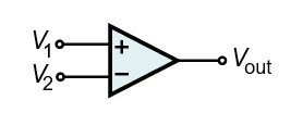
Comparator circuit design
The comparator circuit is designed using an op amp. To make it ready for operation, input voltages are provided. There is no feedback system incorporated with it. A reference voltage and a voltage signal are provided through the op-amp. The positive and negative saturation voltage inputs are also provided. The indicative output is collected from the output of the op-amp.
How comparator circuit works ?
The working principle of the comparator is pretty simple. In general, it compares between two voltage sources and provides a greater output. Below mentioned two points state the working.
- If the voltage in the non-inverting terminal is higher than the inverting terminal voltage, the output is switched to the op-amp’s positive saturation voltage.
- If the inverting terminal’s voltage is higher than the voltage in the non-inverting terminal, the output is switched to the op-amp’s negative saturation voltage.
Voltage comparator circuit using op amp 741
Op-amp 741 is an integrated circuit containing an op amp. A voltage comparator can be created using op amp 741. The below image represents a non-inverting voltage comparator’s circuit diagram using op amp 741.
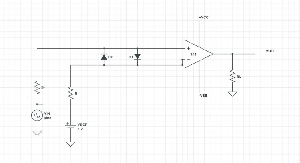
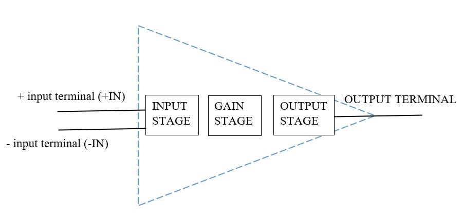
Comparator block diagram
The operation of a comparator can be represented by using block diagrams. The following image represents a block diagram of a comparator,
Comparator circuit relay
Relays are switches that can control a circuit. It can turn On or OFF a circuit and can connect and disconnect a circuit from another circuit. A comparator is broadly utilized as the utilization of the relays.
Comparator circuit uses
A comparator is a valuable and essential device. There are several applications of comparators. Some of the applications of the comparators are listed below.
- Null Detector: If a value is zero, a null detector detects it. A comparator is typically a high-gain amplifier, and for controlled inputs, a comparator is suitable for detecting Null.
- Level Shifter: A level shifter can be designed using a single op-amp. Using a suitable pull-up voltage, the circuit allows for a lot of versatility in selecting the voltages to be interpreted.
- Analog-to-digital Converter (ADC): Comparators are used to create analog-to-digital converters. In a converter, the output indicates which voltage is higher. This operation is the same as a 1-bit quantization. That is why comparators are used in almost every analog-to-digital converter.
- Other than the mentioned applications, there are many other comparators like – Relaxation Oscillator, in Absolute Value Detectors, in Zero-Crossing Detectors, in Window Detectors, etc.
Comparator fuzz circuit
Fuzz circuits can be developed using comparators. LM311 IC is such an example of comparator fuzz. We will discuss this later about LM311.
How to make a comparator ?
A comparator is a particular and straightforward electrical device to build. To build a comparator, we need an op amp and supply voltages. At first, the op-amp is provided with positive and negative saturation voltages. The output will vary in that range of voltages. Then inputs are provided in their inverting and non-inverting terminals. The reference voltage is provided in the non-inverting terminal, and the input voltage is provided in the inverting terminal. There is no feedback system associated with this circuit.
Voltage comparator circuit
A comparator circuit can detect the high-valued voltages between two voltages. Comparators, which typically compare to voltages, are known as a voltage comparator circuit.
Phase comparator circuit diagram
A phase comparator is an analog logic circuit capable of mixing and multiplying. It detects the differences in phases between two given signals by generating a voltage signal. The below image represents the phase comparator circuit diagram.
Ic comparator circuits
As mentioned earlier, a comparator compares two voltage signals and produces an indicative output. Comparators are incorporated inside an integrated circuit for better usability. The below image represents the circuits for comparator ic.
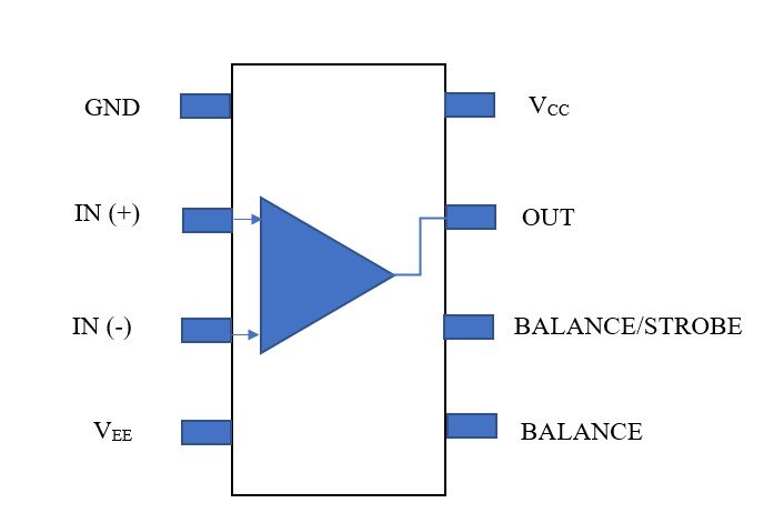
lM358 comparator circuit
lm358 is a comparator ic consisting of two comparators inside it. It has eight pins. This ic doesn’t require any independent external power supply for functioning each comparator. The circuit diagram of the ic is given below.
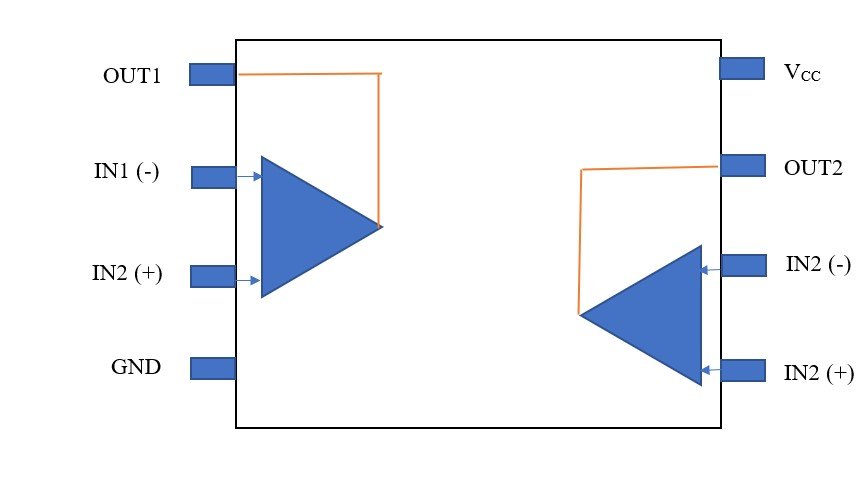
Comparator internal circuit
The comparator is designed using an op amp—the op amp as further circuitry. The internal circuitry inside an ic is given below in the diagram. Observing the diagram, we can see that it consists mainly of transistors, diodes, and resistors. The internal diagram can be divided into three parts based on their operation. They are – input stage, gain stage, and output stage.
Comparator circuit schematic
The schematic diagram of a comparator is given below. The internal schematic diagram is the same as an internal comparator circuit. It has diodes, transistors, and resistors. The internally connected components work as a comparator.
Schmitt trigger comparator circuit
Schmitt trigger is a viral circuit used to improve noise immunity and reduce the likelihood of multiple switching.
A schmitt trigger is a comparator circuit with separate input switching levels for changing the outputs. The schmitt trigger comparator circuit is depicted in the below diagram.

555 timer comparator circuit
555 timer is an oscillator circuit. It is known as 555 timers as there are three resistors of 5 kilo-ohms that are internally connected to provide the reference voltages for both the timer circuits’ comparators. A555 timer ic is used in delay timers, LED flashers, pulse generations, etc. A basic block diagram of 555 timer ic is given below. There are two comparators, an NPN transistor, a flip-flop, three 5k resistors, and an output driver.

comparator circuit using lm324
lm324 is a general-purpose op-amp IC that has four op-amps inside it. It can be used as a comparator also. The op-amps have properties of higher stability, wider bandwidth. LM324 has 14 pins. The pin diagram of lm324 is given below.
| Pin No. | Description |
| 1 | First Comparator’s Output |
| 2 | First Comparator’s Inverting input |
| 3 | First Comparator’s Non-inverting input |
| 4 | 5V supply voltage |
| 5 | Second Comparator’s Non-inverting input |
| 6 | Second Comparator’s Inverting input |
| 7 | Second Comparator’s Output |
| 8 | Third Comparator’s Output |
| 9 | Third Comparator’s Inverting input |
| 10 | Third Comparator’s non-inverting input |
| 11 | Ground PIN (GND) |
| 12 | Fourth Comparator’s non-inverting input |
| 13 | Fourth Comparator’s Inverting input |
| 14 | Fourth Comparator’s Output |
The circuit diagram of the LM324 comparator is depicted in the below diagram.
lm139 comparator circuit
lm139 is another comparator ic. It has four separate precision comparators. The ic is designed to function under a single power supply. It is specially developed for directly interacting with Transistor-Transistor Logic and Complementary MOS logic. The ic comes with a propagation delay of 0.7 microseconds.
The below image depicts the internal circuit diagram of the lm139 comparator.

lm319 comparator circuit
lm319 is another comparator ic having 14 pins. It has two separate precision comparators. The ic is designed to function under a wide range of supply voltages. It is specially developed for directly interacting with Transistor-Transistor Logic and Complementary MOS logic, RTL, DTL. The ic comes with a propagation delay of 0.025 microseconds.
lm311 voltage comparator circuit
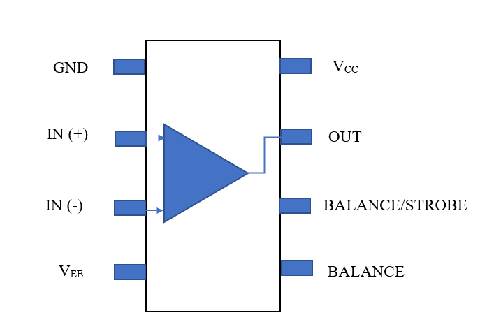
lm311 is another comparator ic having eight pins. It has a single comparator. The ic comes with a response time of a minimum of 0.200 nanoseconds and a typical voltage gain of 200.
The below image depicts the internal circuit diagram of the lm311 comparator.
lm339 comparator circuit
lm339 is another comparator ic. It has four separate precision comparators. The ic is designed to function under a single power supply and for a wide range of voltages. It is specially developed for directly interacting with Transistor-Transistor Logic and Complementary MOS logic and DTL, ECL, MOS logic. The ic comes with a propagation delay of 0.7 microseconds.
Op amp comparator circuit example
Op-amp comparator circuits are used in various applications. For example – to ensure if an input value has reached the peak or the specific value or not, or for quantization in an ADC, also in window detectors, zero-crossing detectors, etc.
Voltage window comparator circuit
A window comparator refers to the circuit that works only in a particular frame or window or voltage. And a voltage comparator compares two signals and provides the output. For a window comparator circuit, there is something called the sandwich effect: if the input voltage goes higher than the low-level reference voltage. The circuit is ON, and if the input voltage gets higher than the high-level reference voltage, then the circuit is OFF.
Components required for a voltage window comparator:
- LM741 op-amps (2)
- 4049 Inverter Chip (1)
- A resistor of 470 ohms (1)
- 1N4006 Diodes (2)
- LED
The voltage window comparator circuit is given in the below image.
<image: vol-win1>
Latching comparator circuit
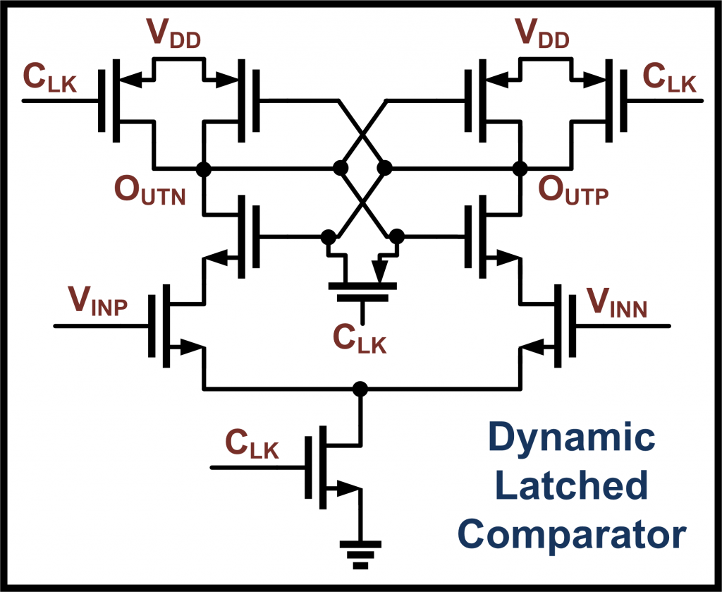
A latched comparator is developed using a StrongArm latch. The StrongArm latch is considered the primary decision amplification stage. The next stage is processed out with a latching element to carry the output load.
Op amp comparator circuit with hysteresis
The difference between Upper Trip Point and Lower Trip Point is Hysteresis. Hysteresis comes with the concept of Schmitt Trigger. If a typical comparator is designed with positive feedback, that circuit causes hysteresis. The below image depicts the circuit diagram.
Regenerative comparator circuit
A Schmitt trigger circuit is also called regenerative comparator circuits. They are used to improve noise immunity and reduce the likelihood of multiple switching Regenerative comparator circuits to design other complex circuits. They are used in ADCs, slicer circuits, memory sensing, etc. The Schmitt Trigger circuit diagram is referred to as the regenerative comparator circuit’s circuit diagram.
Temperature comparator circuit
A temperature circuit is a digital electronic circuit that measures whether the input temperature is below the specified reference temperature. It is one of the primary examples of a comparator circuit. Temperature sensors include a comparator.
Frequently Asked Questions
1. How does a comparator circuit work ?
Answer: The working principle of the comparator is pretty simple. In general, it compares between two voltage sources and provides a greater output. Below mentioned two points state the working.
- If the voltage in the non-inverting terminal is higher than the inverting terminal voltage, the output is switched to the op-amp’s positive saturation voltage.
- If the inverting terminal’s voltage is higher than the voltage in the non-inverting terminal, the output is switched to the op-amp’s negative saturation voltage.
2. Comparator circuit types
Answer: There are several types of comparators. Some of the widely used amplifiers are listed below.
3. Why is the output voltage in the comparator circuit of an op amp equal to the saturation voltage ?
Answer: Comparator circuits do not have any feedback associated with them. The op-amp thus has an open-loop gain. For an ideal op-amp, the open-loop gain is infinite, and for a practical op-amp, the gain is very high. Now, the saturation voltage of typical op-amps is +- 15 V. The op-amp gets saturated at +13 or -13 V. Now, the op-amp gets quickly saturated for a small input voltage. That is why the output voltage in the comparator circuit equal to the saturation voltage.
4. In an op amp comparator circuit, why is a reference voltage used
Answer: Comparison is made between two or more quantities. To indicate which is more significant, we need a reference to decide. We need to determine which voltage is more significant for a comparator. That is why a reference voltage is used to make the decision.
5. How does the digital comparator circuit distinguishes between a lesser and more significant number
Answer: A digital comparator compares two binary numbers. The comparator first finds out the equivalent voltage of the binary numbers and then determines which number is less, which number is significant.
For more Electronics related article click here

Hi, I am Sudipta Roy. I have done B. Tech in Electronics. I am an electronics enthusiast and am currently devoted to the field of Electronics and Communications. I have a keen interest in exploring modern technologies such as AI & Machine Learning. My writings are devoted to providing accurate and updated data to all learners. Helping someone in gaining knowledge gives me immense pleasure.
Let’s connect through LinkedIn –