Specific Enthalpy Vs Enthalpy: Comparative Analysis and FAQs

Capture 5 300x253 1

Specific Enthalpy vs Enthalpy

Enthalpy is a fundamental concept in thermodynamics that measures the total heat content of a system. It is often used to describe the energy changes that occur during chemical reactions or phase transitions. However, there is another term closely related to enthalpy known as specific enthalpy. While both terms are used to quantify energy changes, they have distinct differences in their definitions and applications. In this article, we will explore the differences between specific enthalpy and enthalpy, and understand how they are used in various fields of science and engineering. So, let’s dive in and unravel the mysteries behind these two important concepts in thermodynamics.

Key Takeaways

  • Enthalpy is a thermodynamic property that represents the total heat content of a system, while specific enthalpy is the enthalpy per unit mass of a substance.
  • Specific enthalpy is useful in engineering applications as it allows for more accurate calculations and comparisons between different substances.
  • Enthalpy is typically measured in units of energy, such as joules or calories, while specific enthalpy is measured in units of energy per unit mass, such as joules per kilogram.
  • The specific enthalpy of a substance can be calculated by dividing the enthalpy by the mass of the substance.
  • Both enthalpy and specific enthalpy are important concepts in thermodynamics and are used to analyze and design various processes and systems.

Enthalpy vs Specific Enthalpy

Enthalpy: Definition and Components (Internal Energy and Pressure-Volume Work)

Enthalpy is a fundamental concept in thermodynamics that helps us understand the energy content of a system. It is denoted by the symbol “H” and is defined as the sum of the internal energy (U) and the product of pressure (P) and volume (V) of the system. In other words, enthalpy accounts for both the heat energy and the work done by the system.

The internal energy represents the total energy stored within the system, including the kinetic and potential energies of its particles. On the other hand, the pressure-volume work accounts for the energy transferred to or from the system due to changes in its volume under constant pressure.

Specific Enthalpy: Definition as Enthalpy per Unit Mass
Capture 5
.nuclear-power.com

Specific enthalpy, denoted as “h,” is the enthalpy per unit mass of a substance. It is obtained by dividing the enthalpy (H) of the system by its mass (m). Specific enthalpy allows us to analyze the energy content of a substance on a per-unit-mass basis, which is particularly useful in engineering and thermodynamic calculations.

By expressing enthalpy in terms of mass, specific enthalpy enables us to compare the energy content of different substances or different amounts of the same substance.

Comparison between Enthalpy and Specific Enthalpy

The main difference between enthalpy and specific enthalpy lies in their units and the way they are used. Enthalpy is an extensive property, meaning it depends on the size or amount of the system. On the other hand, specific enthalpy is an intensive property, which remains constant regardless of the system size.

Enthalpy allows us to analyze the total energy content of a system, taking into account both the internal energy and the work done. It is commonly used in thermodynamic calculations, such as determining the heat transfer in chemical reactions or phase changes.

Specific enthalpy, on the other hand, provides a more detailed analysis by considering the energy content on a per-unit-mass basis. It is particularly useful in engineering applications, such as calculating the energy required for heating or cooling a specific mass of a substance.

Units of Measurement for Enthalpy and Specific Enthalpy

Enthalpy is typically measured in units of energy, such as joules (J) or calories (cal). The SI unit for enthalpy is joule, while the calorie is commonly used in the field of chemistry.

Specific enthalpy is expressed in the same units as enthalpy but divided by mass. Therefore, the units for specific enthalpy are joules per kilogram (J/kg) or calories per gram (cal/g).

To summarize, enthalpy and specific enthalpy are both important concepts in thermodynamics. Enthalpy provides a comprehensive analysis of the energy content of a system, while specific enthalpy allows for a more detailed examination on a per-unit-mass basis. Understanding these concepts is crucial for engineers, scientists, and anyone working with energy systems.

Specific Enthalpy of Steam Water System

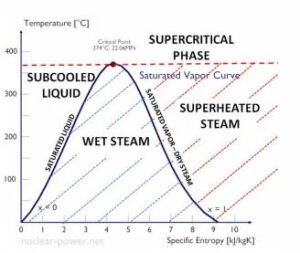
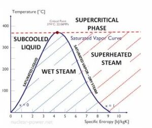
The specific enthalpy of a steam water system is a crucial thermodynamic property that helps us understand the energy content of the system. It is defined as the amount of heat energy per unit mass of a substance, and it plays a significant role in various engineering applications, particularly in the field of thermodynamics.

Specific Enthalpy Values for Vaporization and Saturation of Water

When water undergoes a phase change from a liquid to a vapor state, it requires a certain amount of energy. This energy is known as the specific enthalpy of vaporization. It represents the heat energy needed to convert one unit mass of liquid water into vapor at a given temperature and pressure.

Similarly, the specific enthalpy of saturation refers to the energy content of water when it exists in a saturated state. In this state, water is at the boiling point corresponding to a specific pressure. The specific enthalpy of saturation is the sum of the specific enthalpy of liquid water and the specific enthalpy of vaporization.

Calculation of Specific Enthalpy for Saturated Steam at Atmospheric Pressure

To calculate the specific enthalpy for saturated steam at atmospheric pressure, we need to consider the specific enthalpy of liquid water and the specific enthalpy of vaporization. The specific enthalpy of liquid water can be determined using tables or equations based on temperature. The specific enthalpy of vaporization can also be obtained from tables or correlations.

By adding the specific enthalpy of liquid water and the specific enthalpy of vaporization, we can determine the specific enthalpy of saturated steam at atmospheric pressure. This value represents the energy content of steam in its saturated state.

Increase in Specific Enthalpy with System Pressure

As the pressure of a steam water system increases, the specific enthalpy also increases. This is because higher pressures require more energy to convert water into steam. The specific enthalpy of steam at a given pressure is higher than that at atmospheric pressure due to the additional energy required for vaporization.

The increase in specific enthalpy with system pressure is an important consideration in various industrial processes, such as power generation and steam-driven machinery. Understanding the relationship between pressure and specific enthalpy allows engineers to design efficient systems and optimize energy usage.

Calculation of Specific Enthalpy for Superheated Steam

Superheated steam refers to steam that has been heated beyond its saturation point. To calculate the specific enthalpy for superheated steam, we need to consider the specific enthalpy of saturated steam and the specific enthalpy of superheating.

The specific enthalpy of saturated steam can be determined as mentioned earlier. The specific enthalpy of superheating represents the additional energy required to heat the steam beyond its saturation point. This value can be obtained from tables or correlations based on the temperature and pressure of the superheated steam.

By adding the specific enthalpy of saturated steam and the specific enthalpy of superheating, we can determine the specific enthalpy of superheated steam. This value represents the total energy content of steam in its superheated state.

Molar Enthalpy vs Specific Enthalpy

Definition of Molar Enthalpy and Specific Enthalpy

Enthalpy is a fundamental concept in thermodynamics that measures the total energy of a system. It is denoted by the symbol “H” and is often used to describe heat transfer and energy changes in chemical reactions. Molar enthalpy and specific enthalpy are two related but distinct concepts that are commonly used in different contexts.

Molar enthalpy, also known as molar heat capacity, is the amount of heat required to raise the temperature of one mole of a substance by one degree Celsius. It is represented by the symbol “Cp” and has units of joules per mole per degree Celsius (J/mol·°C). Molar enthalpy takes into account the mass of the substance and is used to calculate the enthalpy change in reactions.

On the other hand, specific enthalpy, also known as specific heat capacity, is the amount of heat required to raise the temperature of a unit mass of a substance by one degree Celsius. It is represented by the symbol “cp” and has units of joules per kilogram per degree Celsius (J/kg·°C). Specific enthalpy is used for heat balance calculations in engineering and is independent of the mass of the substance.

Differences between Molar Enthalpy and Specific Enthalpy

The main difference between molar enthalpy and specific enthalpy lies in the units of measurement and the quantity being considered. Molar enthalpy is expressed in terms of moles of a substance, while specific enthalpy is expressed in terms of kilograms of a substance.

Molar enthalpy takes into account the mass of the substance and is used to calculate the enthalpy change in reactions. It is particularly useful in chemical reactions where the quantities involved are often measured in moles. Specific enthalpy, on the other hand, is used for heat balance calculations in engineering, where the focus is on the energy required to heat or cool a given mass of a substance.

Molar Enthalpy used for calculating enthalpy change in reactions

Molar enthalpy is commonly used in chemical reactions to calculate the enthalpy change, also known as the heat of reaction. The enthalpy change is the difference in enthalpy between the products and the reactants in a chemical reaction. By knowing the molar enthalpies of the reactants and products, it is possible to calculate the enthalpy change using the principle of conservation of energy.

For example, in the combustion of methane (CH4), the molar enthalpy of methane is -890.3 kJ/mol, and the molar enthalpy of carbon dioxide (CO2) is -393.5 kJ/mol. By subtracting the molar enthalpy of the reactants from the molar enthalpy of the products, the enthalpy change of the reaction can be determined.

Specific Enthalpy used for heat balance calculations in engineering

Specific enthalpy is widely used in engineering for heat balance calculations. Heat balance calculations involve determining the amount of heat energy required to heat or cool a given mass of a substance. Specific enthalpy allows engineers to calculate the energy requirements for various processes, such as heating water or cooling air.

For example, in HVAC (Heating, Ventilation, and Air Conditioning) systems, specific enthalpy is used to calculate the energy required to heat or cool air as it flows through the system. By knowing the specific enthalpy of the incoming and outgoing air, engineers can determine the amount of energy needed to achieve the desired temperature change.

Units of measurement for Molar Enthalpy and Specific Enthalpy

Molar enthalpy is measured in joules per mole per degree Celsius (J/mol·°C), while specific enthalpy is measured in joules per kilogram per degree Celsius (J/kg·°C). These units reflect the different quantities being considered – moles for molar enthalpy and kilograms for specific enthalpy.

Calculation of total enthalpy change using Molar Enthalpy and Specific Enthalpy

To calculate the total enthalpy change in a system, both molar enthalpy and specific enthalpy can be used. The molar enthalpy is used to determine the enthalpy change at the molecular level, while the specific enthalpy is used to determine the enthalpy change at the mass level.

The total enthalpy change can be calculated by multiplying the molar enthalpy by the number of moles involved in the reaction and adding it to the product of the specific enthalpy and the mass of the substance. This allows for a comprehensive understanding of the energy changes occurring in a system.

Different Types of Enthalpy Change

Enthalpy change refers to the amount of heat energy transferred during a chemical reaction or physical process. There are various types of enthalpy changes that occur in different scenarios. Let’s explore some of the most common types of enthalpy changes.

Explanation of Various Types of Enthalpy Changes

  1. Enthalpy of Reaction: The enthalpy change associated with a chemical reaction is known as the enthalpy of reaction. It represents the difference in enthalpy between the products and the reactants. This value can be positive or negative, depending on whether the reaction is exothermic (releases heat) or endothermic (absorbs heat).

  2. Enthalpy of Combustion: The enthalpy change that occurs during the combustion of a substance is called the enthalpy of combustion. It measures the heat energy released when a substance reacts with oxygen to form carbon dioxide and water.

  3. Enthalpy of Formation: The enthalpy change when one mole of a compound is formed from its constituent elements in their standard states is known as the enthalpy of formation. It provides information about the stability and energy content of the compound.

  4. Enthalpy of Neutralization: The enthalpy change that occurs when an acid reacts with a base to form a salt and water is called the enthalpy of neutralization. It represents the heat energy released or absorbed during the neutralization process.

  5. Enthalpy of Solution: The enthalpy change associated with the dissolution of a solute in a solvent is known as the enthalpy of solution. It measures the heat energy released or absorbed when a solute dissolves to form a solution.

  6. Enthalpy of Fusion: The enthalpy change when a substance changes from a solid to a liquid state at its melting point is called the enthalpy of fusion. It represents the heat energy required to overcome the intermolecular forces holding the solid together.

  7. Enthalpy of Sublimation: The enthalpy change when a substance changes directly from a solid to a gaseous state without passing through the liquid state is known as the enthalpy of sublimation. It measures the heat energy required to overcome the forces holding the solid together and convert it into a gas.

  8. Enthalpy of Vaporization: The enthalpy change when a substance changes from a liquid to a gaseous state at its boiling point is called the enthalpy of vaporization. It represents the heat energy required to overcome the intermolecular forces holding the liquid together.

  9. Enthalpy of Mixing: The enthalpy change that occurs when two or more substances are mixed together is known as the enthalpy of mixing. It measures the heat energy released or absorbed during the mixing process.

By understanding these different types of enthalpy changes, we can gain insights into the energy transformations that occur during chemical reactions and physical processes. These values play a crucial role in various scientific and engineering applications, such as designing efficient energy systems and understanding the thermodynamics of chemical reactions.

Favorable Enthalpy

Enthalpy is a fundamental concept in thermodynamics that helps us understand the energy changes that occur during chemical reactions. It plays a crucial role in determining whether a reaction is favorable or not. In this section, we will explore the relationship between enthalpy change and reaction favorability, as well as introduce the concept of Gibbs free energy.

Favorability of a reaction based on enthalpy change

The enthalpy change of a reaction, often denoted as ΔH, is a measure of the heat energy absorbed or released during a chemical reaction. It represents the difference in enthalpy between the products and the reactants. By analyzing the sign and magnitude of ΔH, we can determine whether a reaction is exothermic or endothermic.

An exothermic reaction releases heat energy to the surroundings, resulting in a negative ΔH value. On the other hand, an endothermic reaction absorbs heat energy from the surroundings, leading to a positive ΔH value. The magnitude of ΔH indicates the amount of heat energy involved in the reaction.

Relationship between enthalpy change and entropy change

Entropy, denoted as ΔS, is a measure of the disorder or randomness in a system. It accounts for the number of ways in which the particles of a system can be arranged. A positive ΔS value indicates an increase in disorder, while a negative ΔS value suggests a decrease in disorder.

The relationship between enthalpy change (ΔH) and entropy change (ΔS) is described by the equation:

ΔG = ΔH – TΔS

where ΔG is the Gibbs free energy change and T is the temperature in Kelvin. The Gibbs free energy change determines the spontaneity of a reaction. If ΔG is negative, the reaction is spontaneous and favorable. If ΔG is positive, the reaction is non-spontaneous and unfavorable. If ΔG is zero, the reaction is at equilibrium.

Gibbs free energy (ΔG) is a thermodynamic potential that combines the effects of enthalpy change (ΔH) and entropy change (ΔS) to determine the spontaneity of a reaction. It provides a more comprehensive understanding of reaction favorability compared to enthalpy alone.

The equation ΔG = ΔH – TΔS tells us that for a reaction to be favorable, the enthalpy change must be negative (exothermic) and the entropy change must be positive (increase in disorder). However, the temperature also plays a crucial role. At low temperatures, a negative enthalpy change dominates, making the reaction favorable. At high temperatures, a positive entropy change dominates, making the reaction favorable.

Frequently Asked Questions

1. Why are enthalpy values different?

Enthalpy values can vary depending on the specific process or reaction being considered. Factors such as temperature, pressure, and the presence of other substances can influence the enthalpy of a system, leading to differences in the measured values.

2. Is enthalpy the same as specific heat?

No, enthalpy and specific heat are different properties. Enthalpy is a measure of the total energy of a system, including both its internal energy and the work done on or by the system. Specific heat, on the other hand, is a measure of the amount of heat required to raise the temperature of a unit mass of a substance by a certain amount.

3. What is the difference between specific heat capacity and enthalpy?

Specific heat capacity refers to the amount of heat required to raise the temperature of a unit mass of a substance by a certain amount. Enthalpy, on the other hand, is a measure of the total energy of a system, including both its internal energy and the work done on or by the system. While specific heat capacity is a property of a substance, enthalpy is a property of a system.

4. Why is the experimental enthalpy higher than the theoretical value?

There can be several reasons for the experimental enthalpy to be higher than the theoretical value. Experimental errors, incomplete reactions, side reactions, and impurities in the reactants can all contribute to the deviation between the experimental and theoretical enthalpy values.

5. What is the difference between standard enthalpy and enthalpy?

Standard enthalpy refers to the enthalpy change that occurs under standard conditions, which typically include a temperature of 25°C and a pressure of 1 bar. Enthalpy, on the other hand, is a more general term that refers to the total energy of a system, including both its internal energy and the work done on or by the system.

6. What is specific enthalpy?

Specific enthalpy is the enthalpy per unit mass of a substance. It is a measure of the total energy of a unit mass of a substance, including both its internal energy and the work done on or by the substance.

7. What is the difference between enthalpy change and standard enthalpy change?

Enthalpy change refers to the difference in enthalpy between the reactants and the products in a chemical reaction. It can be positive (endothermic) or negative (exothermic). Standard enthalpy change, on the other hand, refers to the enthalpy change that occurs under standard conditions, typically at a temperature of 25°C and a pressure of 1 bar.

8. What is the difference between specific enthalpy and enthalpy?

Specific enthalpy refers to the enthalpy per unit mass of a substance, while enthalpy is a more general term that refers to the total energy of a system. Specific enthalpy takes into account the mass of the substance, whereas enthalpy does not.

9. What is the difference between enthalpy of formation and enthalpy of reaction?

Enthalpy of formation refers to the enthalpy change that occurs when one mole of a compound is formed from its constituent elements in their standard states. Enthalpy of reaction, on the other hand, refers to the enthalpy change that occurs in a chemical reaction, regardless of the formation of new compounds.

10. What is the difference between enthalpy of mixing and enthalpy of solution?

Enthalpy of mixing refers to the enthalpy change that occurs when two or more substances are combined to form a mixture. Enthalpy of solution, on the other hand, refers to the enthalpy change that occurs when a solute is dissolved in a solvent to form a solution.
Bending Strength Of Steel: Several Use Cases And Examples

I channel 300x256 1

This article discusses about bending strength of steel. Bending strength is the ability of a material to resist or withstand the bending stress applied.

Strength is ability to withstand or resist a particular amount of stress. A material has a particular amount of strength, only that much stress it can withstand. Any amount of stress which exceeds the strength can lead to material failure. Simply put, the applied stress should be lesser than the strength of the material for minimizing failure.

What is bending strength?

Bending strength or flexural rigidity is the ability of a work piece to withstand bending stress. The flexural strength depends on the failure load, effective length of the work piece and the dimensions of the cross section of the beam.

Mathematically the bending strength is given as-

σb = M.y/I

where,

sigma is bending strength or maximum allowable bending stress that can be applied before fracture

M is the bending moment

I is the moment of inertia of the cross section of the work piece

What is bending stiffness?

Bending stiffness and bending strength are not same. As discussed above, bending strength is the ability of the work piece to withstand a given amount of bending stress.

On the other hand, bending stiffness tells the amount of deflection the work piece will undergo under a given amount of bending stress. The bending stiffness depends on moment of inertia of cross section the work piece and the modulus of rigidity of the material of work piece.

Mathematically, bending stiffness can be given as-

Bending stiffness = E x I

Where, E is the Young’s modulus or modulus of rigidity

I is the moment of inertia of the cross section of the work piece

Bending strength of stainless steel

The bending strength not only depends on the material but the dimensions of the work piece too. The table below shows the bending strength of a stainless steel bar.

Base metal Bending strength (MPa)
700 W 267
700 F 817
900 W 750
900 F 633
Table: Bending strength of welded stainless steel pipes
Data Source: Investigation on Mechanical Properties of Austenitic Stainless-Steel Pipes Welded by TIG Method – Scientific Figure on ResearchGate. Available from: https://www.researchgate.net/figure/Mechanical-properties-of-the-base-steel-and-four-steel-welded-pipes_tbl1_329360548 [accessed 22 Jan, 2022]

Bending strength of steel pipe

Steel pipes are used at a large scale in industries. It is very important to know the physical properties of steel pipe and the behaviour of these pipes under different types of loads.

Bending strength of steel pipe can be found using the formula given below-

σ = 32MD/π(D4-d4)

where,

D is the outer diameter of pipe

d is the inner diameter of pipe

Pipe is simply a hollow cylinder.

Bending strength of steel plate

Let us assume a steel plate having a depth d and breadth b. The permissible load acting it is P.

The bending strength of this steel plate is given by following-

σ = 3M/bd2

Plate has a rectangular cross section where,

b is the breadth

d is the depth of rectangle

M is the bending moment

Bending strength of steel rod

Steel rods are widely used in construction industry for reinforcement purpose. They are used in aircrafts as well. To avoid construction failure, it is very important to know the mechanical properties of rods being used.

Let us consider a steel rod of diameter d. The bending strength can be given by the following formula-

σ = 32M/πd3

Bending strength of steel bar

Let us assume a circular steel bar of diameter d having permissible force value P. Then the bending strength formula for steel bar will be same as that of steel rod.

The bending strength of steel rod is discussed in above sections.

Bending strength of steel channel

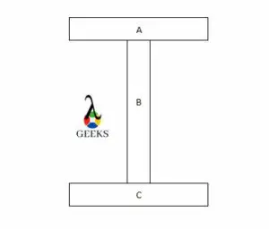
Let us consider a “I” steel channel as shown in the figure below.

Bending strength of steel
Image: Cross section of I channel

To find the moment of inertia of the entire cross section, we add the individual moment of inertia of the parts A, B and C.

The bending strength of this channel can be written from the basic formula. That is,

σb =M.y/I

Bending strength of steel square tube

Square tube is simply a hollow square cross section tube. These tubes are used in construction industry and interior designing. It is very important to know the bending strength of square tube before taking into use.

The section modulus of a square tube can be given by-

σ = bd3/3

Hence the bending strength becomes,

σ = 3M/ bd3

How to calculate bending strength of steel

Bending strength can be found using flexural test. Flexural tests can be performed with a single axial load, three point loading set up and four point loading set up.

Let us consider a three point set up. The given data for the set up is given below-

The work piece is a rectangular bar having breadth of 10cm and depth of 10 cm. The length of the bar is 1m and the load at failure is 10kN.

To find the bending strength of in a three point flexural test, following formula is used-

σ = 3FL/ 2bd2

Substituting all the values in above formula we have,

Bending strength= 15 MPa

How to calculate yield strength of steel

Yield strength of any material can be found using a tensile test on universal testing machine. The machine pulls the work piece from its ends and provides us with a stress strain graph from which we can easily make out the tensile strength of the material.

Let us consider the given data-

Load at failure- 5kN

Area of cross section- 1mm^2

The yield strength can be calculated using the formula-

Syt = P/A

Substituting the values in above equation we get,

Yield strength= 500Mpa

The diagram obtained from this test is commonly called as stress strain diagram.

Stress strain diagram

The graph which shows relationship between stress and strain is called as stress strain diagram.

This graph gives information like yield point, proportional limit, fracture point and ultimate tensile strength of the specimen. This diagram makes it easy to measure the mechanical properties of the specimen.

Low Discharge Superheat: Process, Formula, Work, Example And Exhaustive FACTS

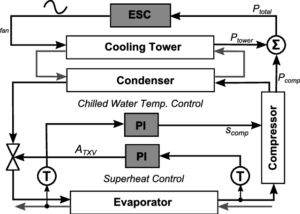
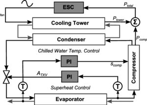
Chiller inner loop controls of superheat and chilled water temperature 3 300x214 1

In this article we will discuss about the “Low discharge superheat” and its related factors.

The Low discharge superheat is when the refrigerant liquid flooding to the compressor or in the screw compressor in the very low oil temperature. The insufficient amount of air flows through the evaporator coils causes low discharge superheat.

With a high ambient temperature the refrigerant liquid go back to the compressor which causes the leakage to the heat exchangers and liquid injection device if it is fitted. This condition also point to an Actuator or Check valve issue. A dirty air filter, evaporator coil or air flow causes discharge measure low. The heat which is carried by the coils is low which result in low discharge superheat.

Process:

The low discharge superheat can be obtaind by the following,

  • At first we need to run the refrigeration system minimum for 10 min.
  • When the system running for a while we have to attach the pipe clamp thermocouple in one side of the refrigerant line which actually separate the thermal expansion valve and the condenser discharge valve.
  • Connect with the refrigerant manifold gauges with discharge service valve.
  • Read refrigerant manifold gauge to check the discharge service valve.
  • Check the thermocouple temperature using a digital thermometer.
  • Measure the pressure chart and temperature for the refrigerant.
  • Now need to turn over the condenser pressure reading to a condenser saturation temp.
  • Pressure takes from the thermocouple and the temperature of the condenser saturation from it.

Formula:

The low discharge superheat is calculated in the way as any other discharge superheat calculated on a system, by measuring the low discharge superheat and have to subtract the suction superheat and then then leaves with a figure of how much low superheat the compressor has given through compression and mechanical/electrical inefficiencies.

Work:

Prevent damage the machine from worn rings, acid formation and oils breakdowns and make it run more effective.

Example:

Let, the Discharge Temperature = 152, Condensing Sat. Temp. = 91

Then the discharge superheat would be = 61

Exhaustive facts:

In the discharge superheat refrigerant is saturated with oil causes low discharge superheat. Low discharge superheat can causes low temperature to the compressor, if the condition goes more low and low then it could damage the compressor too.

What does a low superheat indicate?

The low discharge of a system means refrigerant liquid floods to the compressor for the load is present through the evaporator coil.

When excess amount of refrigerant is enter into the coil or excessive amount of heat present into coil to vaporize the refrigerant properly,that time this condition appear.

Read more about Low Superheat: Important Terms and 3 FAQs

What causes low discharge superheat?

  • Flooding to the compressor with the refrigerant liquid through the evaporator coil. The situation mostly happened when the expansion valve overfeeding to the evaporator or faulty of an actuator.
  • Pressure is too high.
  • Low evaporator air flow.
  • Temperature is low.
  • The shape of the system is over sized during discharge of a superheated liquid.
  • Reduced airflow through the evaporator.
  • Due to low cooling water flow or dirty tubes the refrigerant charge may be excess.
  • Over charged of refrigerant liquid or oil.

Low discharge superheat trane chiller:

With the help of the compressor’s discharge temperature the inside condition of the refrigeration or air conditioning system easily can be recognize. In other term the discharge temperature describe as a measurement of the superheated refrigerant’s vapour temperature.

Formula-

Discharge Superheat = Temperature of discharge connection – Saturated temperature of the liquid line.

Purpose:

This is used to point an actuator or check the valve issue. The Trane chillers are used to system for improve the efficiency mechanical or electrical to the compressor,deliver the correct amount of the temperature, humidity. During the flooding of the refrigerant liquid or oil the sound of the system is increases, with the Trane chillers the sound became less which impact is good for the environment .The Trane chillers deliver ventilation for the space and also helps to minimize the operating cost.

York yvaa low discharge superheat:

The low discharge superheat faults due to reason of the quantity of oil in the oil separator causes York Yvaa low discharge superheat. For this reason the oil charge is reduced in these specific circuits to correct the nuisance superheat trips. The change is only applicable to the circuits.

Procedure:

  • The first step is to identify the unit and the amount of the oil. The oil should be taken as that much quantity with which it could be removed as per the corresponding compressor.
  • As per the correct size the compressors are verified.
  • Need to walkout the unit.
  • After that need to discharge the unit.
  • A container is used which should be have measuring indicators gradually.
  • In the next step required oil is removed from the container.
  • The oil is separate from the compressor on the oil line.
  • In the starting if the refrigerant was removed from the low discharge superheat then make sure to correct the refrigerant level.
  • Adding the adjusted refrigerant to the system.
  • Apply unit to the system.
  • For about one hour the unit should be operate at full load.
  • Finally need to note down the oil level from the oil separator.

York low discharge superheat:

Low discharge superheat usually the situation occurs because of overcharge of refrigerant or overcharge of oil. Both condition gives lower discharge temperature. Once the refrigerant is saturated with oil low discharge will continue to occur.

Low discharge superheat sensor:

In the low discharge superheat all chillers will have a certain amount of the oil in the refrigerant, a little amount of oil is good but the system but too much is not good for the entire system. An excess amount of present of oil can cut blade from the impeller and reduce the efficiency of the compressor and also minimize the percentage of the heat transfer. For the recovery from this unwanted situation in the low discharge superheat’s chillers recovery equipment is needed, the recovery equipment is called the low discharge superheat sensor.

The main purpose of the sensor is to sense the oil which is float on the top of the refrigerant. The low discharge superheat condition is happened when the refrigerant liquid flooding into the compressor, or in the case of screw compressor, low cold oil temperature.

Low discharge superheat in chiller :

In the application field after doing the investigation we could find that the performance of the chillers attached with an electronic expansion valve. The chillers mainly work in steady state and transient condition. .The chillers capacity works in both hot and cold starts.

In low pressure the chillers start to work, at this condition the refrigerant enter to the evaporator. In case of low discharge superheat the capacity is very fast. In the cooling condition the chillers leading to low off/on cycling losses. The expansion valve works on the both steady and transient state of the chillers.

The capacity of the chillers is about 25 kW.  The chillers mainly consists four components. The components are compressor, evaporator, expansion unit and condenser. Every chillers system has refrigerant.

What is good discharge superheat?

The temperature of the ideal discharge superheat is about 10K-15K.

Frequently Asked Questions:

Q.What is low discharge superheat?

When a little amount of air could passes to the system for the reason of stopping the head load entry through the evaporator coils,which occur low discharge superheat.

The low discharge indicates that the quantity of refrigerant liquid or oil present in the compressor.

How To Calculate Superheat: Process, Formula, Work, Example

How to calculate superheat

Dive into our comprehensive guide designed to clarify your doubts on ‘How to Calculate Superheat.’ This article provides step-by-step instructions, practical examples, and essential tips to accurately measure superheat in various systems, ensuring a clear understanding of this crucial HVAC concept.

It is calculated by obtaining the difference between two temperatures. The one temperature is the outlet temperature of the evaporator, and the second temperature is converted with pressure.

How to calculate superheat

The temperature measurement is done by using the contact type thermometer.

The superheat level indicates the level of the refrigerant present in the evaporator. If the superheat is higher than the average level, the refrigerant is less than the required level in the evaporator.

The following are the reason for the lower refrigerant in the system,

  • The technician has charged low refrigerant than an actual level requirement
  • the device resists refrigerants like orifices, thermocouples etc.
  • The heat load on the evaporator is higher than the average level

How to calculate target superheat?

The target superheat of the air conditioning system can be obtained by the following.

The target can be calculated with wet bulb temperature near to evaporator inlet and the outside dry bulb temperature.

After obtaining both temperatures, the following formula calculates the target superheat.

Target superheat = (3 * Wet bulb temperature – 80 – Dry bulb temperature)/2

The instrument used for the indoor wet bulb temperature measurement is a digital psychrometer. The instrument used for outside dry bulb temperature measurement is the digital temperature measuring instrument.

The dry bulb temperature remains same in the most case. The target can vary with the change in the wet bulb temperature. At the time of refrigerant charging, the wet bulb temperature is changing.

To obtain proper refrigerant charging, the target superheat is maintained near the actual superheats.

Lets’s understand target superheat with the following calculation,

Suppose, Wet bulb temperature = 64 ° F

Dry bulb temperature = 86 ° F

An equation to calculate target superheat

Target superheat = (3 * Wet bulb temperature – 80 – Dry bulb temperature)/2

Target superheat = (3 * 64 – 80 – 86)/2

Target superheat = (192 – 80 – 86)/2

Target superheat = (26)/2

Target superheat = 13° F

How to calculate superheat in a freezer?

The calculation of the superheat in the freezer is similar to the refrigerator.

The superheat in the freezer is the difference between saturation temperature and freezer outlet temperature.

A pressure-temperature chart obtains the saturation temperature. The evaporator’s outlet temperature is measured with a digital thermocouple. Take the difference between both temperatures.

The answer to the difference is the value of the superheat for the freezer.

How to calculate superheat in a chiller?

The superheat of the chiller can be calculated with the following steps

  • Identify the suction line for measurement of pressure.
  • To obtain the pressure of the suction line, Fix the pressure gauge near the condenser coil.
  • Attach the thermocouple at the outlet of the evaporator coil. The service port is provided for the thermocouple.
  • Note the reading of pressure after the system achieves steady flow.
  • Note the reading of the temperature at the same time.
  • Convert the reading of pressure into the corresponding temperature using a pressure-temperature saturation chart.
  • Take the difference between the corresponding temperature and the evaporator’s outlet temperature reading.
  • The answer to the difference is the value of the superheat.

This process of calculating the superheat remains the same for refrigeration and another similar system.

How to calculate superheat on a heat pump?

The heat pump is functioning opposite to the refrigerant. The superheat can be calculated with the following steps.

  • Identify the suction line in the system as the suction line always has more cross-sectional area than another line
  • To measure the suction line pressure in the system, install the pressure gauge neat to the condenser coil.
  • Attach the temperature measuring device to the outlet of the evaporator coil. The service port is provided for the measuring device.
  • Note the reading of pressure after the system achieves steady flow.
  • Note the reading of the temperature at the same time.
  • Convert the reading of pressure into the corresponding temperature using a pressure-temperature saturation chart.
  • Take the difference between the corresponding temperature and the evaporator’s outlet temperature reading.
  • The answer to the difference is the value of the superheat.

This process of calculating the superheat remains the same for refrigeration and another similar system.

T-S diagram for heat pump and refrigeration
T- S Diagram heat pump Credit wikipedia

For example :

If the low side pressure reading of the gauge is 120 PSIG.

The corresponding conversion of the pressure into temperature with a pressure-temperature chart. The value of temperature is 42 ° F.

The temperature measurement at the outlet of the evaporator is 50 ° F.

Now, take a difference between the corresponding temperature and the saturation temperature at the evaporator.

Superheat = Corresponding temperature at the low side – Temperature measured at the evaporator

Superheat = 50 – 42

Superheat = 8 ° F

So, With these simple steps, we can calculate the superheat of the system. The superheat in this example is 8 ° F.

How to calculate evaporator superheat?

The evaporator superheat calculation remains the same as in the refrigerator.

It is a difference between the measured evaporator outlet temperature and the corresponding saturation temperature.

The vapour line temperature is measured by identifying the large cross-section of the suction line. The temperature measurement is not the same in the refrigeration and the air conditioning.

The temperature and the low side pressure of the system are measured after achieving the steady flow condition. The measurement of the system will change if measured immediately after starting.

How to calculate superheated steam temperature?

The superheated steam is generally generated in the higher pressure boiler.

The degree of superheat is obtained by using either a steam table or Mollier diagram. The energy is required to raise the temperature of the saturated steam.

The temperature of the superheated steam is always greater than 100 ° C at the standard pressure condition.
How to calculate superheat R22?

The superheat in the system with R22 is calculated by the following equation

Total Superheat with R22 = Corresponding temperature at suction pressure – Temperature measured at a suction line or outlet of the evaporator

The superheat is nearby 10 ° F  in most cases. If the superheat is high, then it causes an increase in the heat of compression. This increase in temperature can affect the performance of the compressor. It is required to maintain and monitor the superheat continuously on the system.
How to calculate superheat 404a?

There are two types of superheat in the refrigeration system.

Total Superheat with R404a = Corresponding temperature at suction pressure – Temperature measured at a suction line or outlet of the evaporator

The refrigeration system can be analyzed with evaporator superheat, and the compressor superheat. The evaporator superheat always less than the compressor superheat. The compressor superheat also called the total superheat.

To obtain total superheat for R404, one has to measure temperature at the inlet of temperature with a temperature measuring device. Also, measure the pressure at that location.

The compressor superheat is the sum of the evaporator superheat and vapour line or suction line superheat.

The range of low side pressure for the R404 is nearby 20 psig in the usual case, and the inlet temperature of the compressor is 25° C approx.

For the safe operation of a system with R404 refrigerant, the recommended superheat should be in the range of 20° C to 30° C. If the superheat with R404 is more than the above value, then it can deteriorate the performance of the compressor or system.

How to calculate superheat
TXV to control superheat Credit Wikipedia

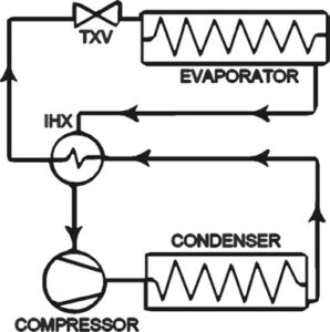
The thermal expansion valve is the device used to control the superheat in the refrigeration system. The expansion of TXV can control the evaporator superheat. It can reduce the total superheat at the desired level for efficient working of the system.

How to calculate superheat 410a?

The superheat in the system with R410a is calculated by the following equation

Total Superheat with R410a = Corresponding temperature at suction pressure – Temperature measured at a suction line or outlet of the evaporator

To obtain total superheat for R410a, one must measure temperature at the inlet of temperature with a temperature measuring device. Also, measure the pressure at that location.

Bending Stress Formula: Several Use Cases And Examples

Bending stress derive1 300x181 1

This article discusses about bending stress formula for different types of beam configurations. We all know that when an object curves due to application of load then it is said to be subjected under bending.

It is very important to know the amount of bending stress being experienced by the work piece. The work piece will break if the applied bending stress exceeds more than the maximum allowable bending stress. The bending strength of the material is the maximum amount of bending strength that can be applied on the work piece before the work piece starts to fracture.

What is bending stress?

Let us start our discussion with the definition of bending stress. It is simply the stress which is responsible for bending of the work piece.

In further sections we shall see the mathematical forms of bending stress for various beam configurations and cross sectional shapes.

What is a beam?

A beam is a structural element that is mainly used for supporting the primary structure. The beam is not necessarily a support, it can itself be a structure for example bridges and balconies.

Most commonly used beams in industry are cantilever beams, simply supported beams and continuous beams.

Bending stress formula for beam

The bending stress depends on the bending moment moment of inertia of cross section and the distance from the neutral axis where the load is applied.

Mathematically, it can be represented as-

σ = My/I

y it he distance from the neutral axis

I is the moment of inertia of cross section

In terms of section modulus-

σ = M/Z

where,

Z is the section modulus of the beam

M is the bending moment

Bending stress formula units

The formula of bending stress can be given as-

σ = My/I

The formula in terms of units of each quantity can be given as-

Units = N – mm x mm/mm4

From above, we can derive that the units of bending stress is-

Units = N/mm2

Allowable bending stress formula

The allowable stress is the value of stress beyond which stress should not be applied for safety reasons. The allowable bending stress depends on the flexural rigidity of the material.

The allowable bending stress formula can be given as-

σallowable = σmax/Fs

where,

Fs is the factor of safety

Bending stress formula derivation

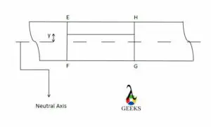
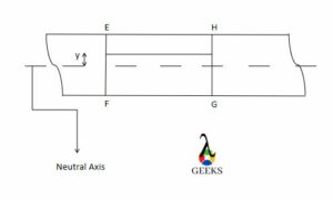
Let us consider a beam section as shown in the diagram below-

bending stress formula
Image: Beam

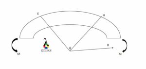
Let us assume a moment, M is applied on the beam. The beam curves by an angle theta and makes a radius of curvature R as shown in figure below-

Bending stress derive2
Image: Bending moment on beam

The strain in neutral axis is zero. Whereas the strain acting on the line where force is applied experiences strain. Balancing all strain values we get total strain,

(R + y)θ – Rθ/Rθ = y/R

Strain is also given by-

Strain = σ/E

from above equations we can conclude that,

σ/y = E/R

Now,

M = Σ E/R x y2

and,

δA = E/R Σ y2 δA

M = E/R x I

From above equations we conclude that,

σ/y = E/R = M/I

Hence derived.

Bending stress formula for rectangular beam

Depending upon the cross section of the beam, the moment of inertia changes and hence the bending stress formula.

The moment of inertia of rectangle is given as-

I = bd3/12

From above, bending stress formula for a rectangular beam can be written as-

σ = 6M/ bd2

Bending stress formula for hollow rectangular beam

Hollow beams are used to reduce the weight of the beam. These beams can be used in light weight applications.

Let us consider a beam with hollow rectangular cross section with outside length as D and inner length as d, outside breadth as B and inner breadth as b.

The section modulus of this cross section will be-

Z = 1/6D x (BD3 – bd3)

Hence the bending stress formula for a hollow beam can be given by-

σ = 3M/(BD3 – bd3)

Bending stress formula for circular cross section

Let us consider a beam having a circular cross section of diameter D.

The moment of inertia of circular section can be given by-

I = πD4/64

From above, we can write the bending stress formula for circular beam as-

σ = 32M/ bd3

Bending stress formula for hollow shaft

Let us consider a hollow circular shaft having inner diameter d and outside diameter D.

The moment of inertia of hollow circular section can be given as-

I = π (D4-d4)/64

From above, the bending stress can be written as-

σ = 32MD/π(D4-d4)

Bending stress formula for pipe

A pipe is simply a hollow circular shaft. So the bending stress formula is same as that of hollow circular shaft.

That is,

σ = 32MD/π(D4-d4)

Maximum bending stress for simply supported beam

The general formula for bending stress remains the same that is-

σ = My/I

However, the formula is modified as per the type of loading. The loading can be in the form of point load, uniformly distributed load or uniformly variable load. In further sections we shall see the different formulae for simply supported beams in different forms of loading.

What is bending moment?

The reaction induced in a structural element or the bending effect produced when an external load is applied on the beam (structural element).

Bending moment formula for different beam configurations under different types of loading is discussed in below sections.

Bending moment formula for fixed beam

A fixed beam is a type of beam which is fixed at both the ends. At both the ends the reaction forces are present. The bending moment formula for fixed beam under different types of loading is given below-

  • Bending moment under UDL or Uniformly distributed load

The formula for bending moment of fixed beam under UDL is given as-

M = ωL2/12

  • Bending moment under point load

The formula for bending moment of fixed beam under point load is given as-

M = ωL/8

  • Bending moment under trapezoidal load or UVL or uniformly variable load

The formula for bending moment of fixed beam under trapezoidal load is given as-

M1 = ωL2/30

For other side,

M2 = ωL2/20

Bending moment formula for continuous beam

The bending moment of continuous under different types of loading is shown below-

  • Bending moment under UDL

To find the bending moment of continuous beam under uniformly distributed load, we need to find the reaction forces at the end points. After that we have to apply equilibrium conditions that is sum of all horizontal and vertical forces is zero as well as moments is zero. To solve UDL, we multiply the length with the magnitude of UDL. For example, if 2N/m of UDL is applied till 4m length of work piece then the net load acting will be 2×4= 8N at center that is at 2m.

  • Bending moment under point load

The procedure is same as for UDL. The only difference is that here we know the magnitude of force and the distance at which it is acting so we need not convert it into point load as we did for UDL.

  • Bending moment under UVL or uniformly varied load

To solve UVL, we need to find the area of the triangle formed by UVL. The area is the magnitude of point load that will be acting due to UVL. The distance from vertex will be L/3 at which the point load will act. Rest of the procedure is discussed above.

Bending moment formula for rectangular beam

Bending moment of the beam does not depend on the shape of the beam. The bending moment will change as per the loading conditions and the type of beam (whether continuous, cantilever simply supported etc).

Only the moment of inertia changes with the shape of the cross section of the beam. This way the bending stress formula changes. The bending stress formula for rectangular cross section is discussed in above section.

Bending moment formula for UDL

UDL or uniformly distributed load is the type of load which is applied to a certain length of the work piece and is equal in magnitude wherever applied.

The bending moment formula for UDL of different beam configurations are given below-

The formula for bending moment of simply supported beam under UDL is given as-

M = ωL2/8

  • For cantilever beam-

The formula for bending moment of cantilever beam under UDL is given as-

M = ωL2/2

Bending moment formula for point load

Point load is the type of load which acts only at a particular point on the surface of the work piece.

The bending moment formulae for point loads for different beam configurations are given below-

  • For simply supported beam: The formula for bending moment of simply supported beam under point load is given as- M = ωL/4
  • For cantilever beam: The formula for bending moment of cantilever beam under point load is given as- M = ωL

For other beam configurations, the formula for bending moment is discussed in above sections.

Bending moment formula for trapezoidal load

Trapezoidal load is a type of load which is applied to a certain length of the work piece and varies linearly with length. Trapezoidal load is combination of both UDL and UVL. Lets assume magnitude of UDL as zero to ease our calculations.

The bending moment for different beam configurations under trapezoidal load are given below-

  • For simply supported beam– The bending moment of simply supported beam under trapezoidal load is given as- M = ωL2/12
  • For cantilever beam– The bending moment of cantilever beam under trapezoidal load is given as- M = ωL2/6

For other beam configurations, the formula is discussed in above section

Summary of bending moment formula

Table below shows a brief summary of formula for different beam configurations under different types of loading

Type of beam Point load UDL UVL
Cantilever wL (WL^2)/2 (WL^2)/6
Simply supported wL/4 (WL^2)/8 (WL^2)/12
Fixed wL/8 (WL^2)/12 (WL^2)/20
Table: Maximum bending moments of different beam configurations under different types of loading

Summary of bending stress formula

Table below shows a brief summary of formula for bending stresses of different beam cross sections

Cross section Bending stress
Rectangular 6M/(bd^2)
Hollow rectangular 3M/BD^3-bd^3)
Circular 32M/bd^3
Hollow circular 32MD/(D^4-d^4)
Table: Summary of bending stress formula

3 Unilateral Tolerance Examples: Explanations And Detailed Facts

DIA 0

Unilateral Tolerance examples are generally observed in interchangeable manufacturing processes specially where precision fits are required.

A Unilateral Tolerance basically signifies a nominal size and either a plus or a minus tolerance. In Unilateral Tolerance the allowable size variation is only in one direction, it can be positive or negative and zero value is also permitted.

Tolerance or permissible variation of dimension is always allowed during machining of a mating component or any engineering parts to avoid high cost and long time consumption.

The permissible deviation of true dimension of a mating part without hindering any functional accuracy and useful for actual working is known as tolerance.

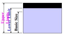
Tolerance zone indicates the difference between the upper and lower limit of deviation.

There different types of tolerances are listed below:

  • Unilateral Tolerance
  • Bilateral Tolerance
  • Compound Tolerance
  • Geometric Tolerance

Here we are going to discuss mainly about Unilateral Tolerance

Unilateral Tolerance Examples
Unilateral Tolerance;  Image Credit: home.iitk.ac.in

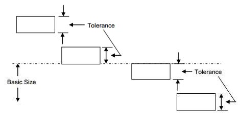
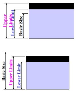
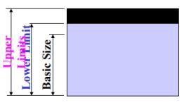
The diagram shows us that the tolerance lies only on one side of the basic size. It may be above or below the nominal dimension.

Some examples of Unilateral Tolerances are given below to get a clear idea:

  • 12.0mm +0/+0.5mm
  • 5.5″ +0.010″/+0.015″
  • 5.325″ +0/-0.002″
  • 7.1mm -0.5/-0.6mm

The above examples can be illustrated elaborately as below:

Nominal SizeBottom ToleranceTop Tolerance
12.0mm12.0mm12.5mm
5.5″5.51″5.515″
5.325″5.325″5.323″
7.1mm6.6mm6.5mm

What is Unilateral Tolerance?

During machining of mating parts Unilateral Tolerance assist the operators to calculate the deviation in a easy and simple way.

In Unilateral tolerance the variation from the original profile is only allowed in one direction i.e tolerance limits lie only above or below the basic size. Here the variation in dimension is permitted only in one direction, not in both the directions.

Unilateral Tolerance is most widely used especially in case of precision fits due to its simplicity in determining the deviations.

DIA 2
Unilateral tolerance;Image Credit: theengineerspost.

Example of Unilateral Tolerance for machining a shaft:

DIA 3 4

Here we try to achieve a diameter of 25 cm, known as basic or nominal size. The deviation from the basic size is permitted as +0.02 cm as upper limit and +0.01 cm as lower limit. Here the variation in dimension is allowed only in positive direction or above the basic size.

Basic size: 25 cm

Upper limit: 25+.02=25.02cm

Lower limit: 25+.01=25.01cm

DIA4 3
Unilateral Tolerance; Image Credit: getmyuni.azureedge.

How to calculate Cpk for Unilateral Tolerance?

Unilateral or one-sided tolerances impose only an upper limit or a lower limit on the process, and leave the specification unbounded on the other side.

The Process Capability Indices Cp & Cpk can be calculated by using the following formulae:

Cp = USL-LSL/6σ

gif
gif
gif

Where USL=Upper Specification Limit

LSL=Lower Specification Limit

0

The process capability index Cpk is used in manufacturing industry to calculate the ability of the process to meet customers’ expectations. In this competitive world to sustain in the market the good knowledge of Cp and Cpk value is a powerful strategy.

In general, higher the Cpk value, the better the product or process that means the process or the product has a higher ability to satisfy the customers. In other words an improvement in the process results a higher Cpk value.

Cpk is calculated by determining the difference between mean value and specification(upper and lower), then this difference is divided by 3 x standard deviation. The value obtained indicates the process capability, higher value means better product or process.

Cpk=Zmin/3

Zmin=Smaller of Zupper or Zlower

Zupper=[(USL-Mean)/Estimated sigma*]

Zlower=[(Mean-LSL)/Estimated sigma*]

Estimated sigma=average range/d2

In case of Unilateral Tolerance we have only one specification or tolerance either upper tolerance or lower tolerance. For example in our example we have only upper tolerance value but no lower tolerance.

In this case we can go for two options

  • Considering LSL as 0
  • Lower specification or tolerance is missing and calculation is done without considering it.

Let here USL=0.5

And estimated sigma=0.15

In case of the 1st option,

We consider LSL=0

Zupper = [0.5-0.0025/0.15] = 3.316

Zlower = [0.0025-0/0.15] = 0.01667

Zmin = 0.01667

Cpk = 0.01667/3 = 0.005

This value of Cpk i.e. 0.005 cann not satisfy a customer .

In case of the 2nd option,

Here we assume that lower specification or tolerance is missing, without LSL, obliviously Z lower value is also missing.

Zupper=3.316(from above)

Cpk=3.316/3=1.10

A Cpkof 1.10 is more realistic than one of 0.005.

From the above example it is clear that Cpk can be calculated when only one deviation exists, using only the available specification and the other one specification is considered as missing. Now consider either the upper limit( Zupper) or the lower limit( Zlower).

If we consider lower specification as zero it will give a lower value of Cpk which is not advisable.

How to convert Unilateral Tolerance to Bilateral Tolerance?

A bilateral tolerance is plus AND minus whereas a unilateral tolerance is a plus OR minus tolerance.

In case of Bilateral Tolerance variation from the true profile is permitted in both directions whereas in case of Unilateral Tolerance variation is allowed only in one direction.

DIA10
Unilateral Tolerance;Image Credit: https://ncet.co.in/

1
Bilateral Tolerance; Image Credit: https://ncet.co.in/

Let us consider an example of a Unilateral Tolerance is

2 1
DIA13 1
DIA12

Here Basic size: 40.0

Upper Tolerance:40.0+0.0=40.0

Lower Tolerance:40.0-0.5=39.5

Now if we try to convert this Unilateral Tolerance into Bilateral Tolerance, then it will be:

Divide the total tolerance by 2,   -0.5/2= -0.25

Determine the mean dimension,  40.0-0.25= 39.75

Now write as a bilateral tolerance  ,

For this new bilateral form

Basic size: 39.75

Upper Tolerance:39.75+.25=40.0

Lower Tolerance:39.75-0.25=39.5

We can convert Unilateral tolerance into Bilateral Tolerance keeping the Tolerance zone same and including both +ve and –ve tolerance.

How to find Unilateral Tolerance?

Unilateral Tolerance is a unequally disposed tolerance where deviations lie only in one direction of the nominal size.

Unilateral Tolerance consists of one nominal size or basic size and a plus or minus deviation. Using these values we can easily calculate the Unilateral Tolerance given for a component.

Considering an example of Unilateral Tolerance ,

1)

DIA 3 3

Basic size: 25 cm

Upper limit: 25+.02=25.02cm

Lower limit: 25+.01=25.01cm

Tolerance Zone=25.02-25.01=0.01cm

2)

DIA14

Basic size: 25 cm

Upper limit: 25-.01=24.90cm

Lower limit: 25-.02=24.80cm

Tolerance Zone=24.90-24.80=0.10cm

DIA15
Examples of Unilateral Tolerance;Image Credit: getmyuni.azureedge.

Types of Tolerance: Explanation, Comparative Analysis, Examples

Capture 1 2

Types of Tolerances used in a technical drawing mainly indicate the permissible amount of deviations from the original dimension.

Tolerance can be classified as follows

  • Unilateral Tolerance
  • Bilateral Tolerance
  • Compound Tolerance
  • Geometric Tolerance

Tolerance or permissible variation of dimension is always allowed during machining of a mating component or any engineering parts to avoid high cost and long time consumption.

 The permissible deviation of true dimension of a mating part without hindering any functional accuracy and useful for actual working is known as tolerance.

Unilateral Tolerance: In Unilateral tolerance the variation from the original profile is only allowed in one direction i.e tolerance limits lie only above or below the basic size. Here the variation in dimension is permitted only in one direction, not in both the directions.

Bilateral Tolerance: In Bilateral Tolerance the size of the part varies above and below the basic size, i.e. the variation in dimension is in both the directions.

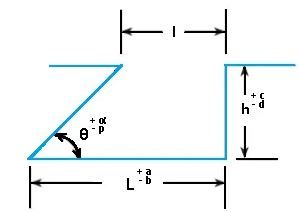
Compound Tolerance: Compound Tolerance can be calculated by adding or subtracting multiple Tolerances associated with different dimensions. Compound Tolerance is derived by using different established Tolerances (for e.g. lateral, angular etc). 

types of tolerances
Compound Tolerance; Image Credit: htheengineerspost.com

From the above figure it is clear that Compound tolerance on I  is dependent on tolerances of L, h and θ.Here I is the combination of three tolerances .The minimum tolerance on ‘l’ will be corresponding to L-b, θ+∝ and h+c.

Geometric Tolerance: Geometrical tolerances are associated with certain geometrical features like flatness of a plane surface, straightness of a cylinder, squareness of a square shape, roundness etc.

While defining the tolerances of a complex structure requiring various tolerances in multiple dimensions, it is important to note the individual tolerance provided are kept on check so that, the cumulative effect of tolerance build-up doesn’t make the overall tolerance to be un undesirable range.

This is particularly true in case of specifying dimensional geometric tolerances which are frequently used to indicate the relationship of one part to another. This is also called positional tolerance which is a 3 dimensional geometric tolerance comprising of position, symmetry and concentricity of various parts making up the object.

What is Compound Tolerance?

Compound Tolerance is a combination of established tolerances on more than one dimensions.

Compound Tolerance is determined by combining  more than one tolerances associated with different dimensions, these tolerances may be angular or lateral.

Compound Tolerance Examples

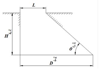
Example of a Compound Tolerance is given below:

Capture5
Compound Tolerance; Image Credit: getmyuni.azureedge.

Here to calculate tolerance for the dimension L we have to consider tolerances associated with D,H and ϴ.

The maximum limit of L can be obtained when base is D+a, angle is ϴ+a and vertical is H-d.

The minimum limit of L can be obtained when base dimension is D-b , angle is ϴ-b and vertical dimension is H+c.

What is Bilateral Tolerance?

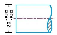
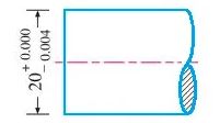
It is the type of tolerance where only the nominal size is defined and error margin is provided on both upper and lower end, both of which are having same absolute value.

In case of Bilateral Tolerance variation from the true profile is permitted in both directions.

Capture3
Bilateral Tolerance; Image Credit: theengineerspost.

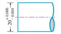
Here Basic size:20 mm

Upper limit:20+0.002=20.002 mm

Lower limit:20-0.002=19.998 mm

DIA11
Bilateral Tolerance; Image Credit: https://ncet.co.in/

What is Unilateral Tolerance?

During machining of mating parts Unilateral Tolerance assist the operators to calculate the deviation in a easy and simple way.

In Unilateral tolerance the variation from the original profile is only allowed in one direction i.e tolerance limits lie only above or below the basic size. Here the variation in dimension is permitted only in one direction, not in both the directions.

DIA 2 1
Unilateral Tolerance; Image Credit: theengineerspost.com

Example of Unilateral Tolerance for machining a shaft:

DIA 3 5

Here we try to achieve a diameter of 25 cm, known as basic or nominal size. The deviation from the basic size is permitted as +0.02 cm as upper limit and +0.01 cm as lower limit. Here the variation in dimension is allowed only in positive direction or above the basic size.

Basic size: 25 cm

Upper limit: 25+.02=25.02cm

Lower limit: 25+.01=25.01cm

DIA4 4
Unilateral Tolerance; Image Credit: getmyuni.azureedge

Bilateral Tolerance Examples

In case of Bilateral Tolerance Upper and Lower limit values lie on both sides (above and below) of basic value.

Examples of Bilateral Tolerance are:

Capture4

Here

 Basic size:25 mm

Upper limit:25+0.02=25.02 mm

Lower limit:25-0.02=24.98 mm

Capture6

Here

 Basic size:25 mm

Upper limit:25+0.02=25.02 mm

Lower limit:25-0.01=24.99 mm

Why Unilateral Tolerance is preferred over Bilateral Tolerance?

In Unilateral Tolerance variation is made only in one direction from the basic size as against bilateral tolerance, where the upper and lower limit of values lies on the both sides of basic value.

There are a good number of reasons for preference of unilateral tolerance as it provides significantly higher advantages over bilateral tolerance.

  • The deviation from basic size is only in one direction due to which it is easy and simple to calculate the tolerances.
  • suitable for interchangeable manufacturing processes specially where precision fits are required.
  • In Unilateral Tolerance Go Gauge ends can be standardized as the holes of different tolerance grades possess same lower limit and all the shafts have same upper limit.
  • In case of Unilateral Tolerance the chance of rejection in  machining the mating parts is very less. The operator can machine the upper limit of the shaft or lower limit for the hole, because he get extra margin to modify if changes are required later during final fitup.

Why use Unilateral Tolerance?

Reasons to use Unilateral Tolerance are :

  • Here deviation is allowed only in one direction from the basic dimension so it is easy and simple to calculate.
  • Unilateral Tolerance system is preferred for interchangeable manufacturing processes mainly where precision fits are required.
  • Helps to standardise Go gauge end.
  • In this system tolerance can be revised without changing the type of fit.
  • This system minimizes the chance of rejection during machining of a component. Operators can machine the maximum dimension of the shaft and minimum dimension of the hole without any tension and they have enough margin before anything goes wrong.

Why use Bilateral Tolerance?

In industrial practice, bilateral tolerance is more of a norm than an exception. It provides flexibility to the machinist and in a sense more convenient for the designer to specify.

  • Providing a bilateral tolerance allows a machinist the margin of error on both side of the target value
  • While specifying a dimension drawing of say, a shaft and a hole, if bilateral tolerance is specified, only changing the nominal size of a shaft or hole is enough to rescale the drawing.
  • These are suitable for large scale manufacturing where machine is set for a basic size of a part

3 Bending Stress Examples: Detailed Facts

This article discusses about bending stress example. When an object curves as a result of stress applied on it, then the corresponding stress is called as bending stress.

The radius of curvature is visual proof that the object is under the state of bending. Bending can lead to mechanical failure for mechanical tools. The tools may break due to excessive bending and hence it is very important to know the amount of bending stress being applied.

What do you mean by bending?

As discussed in above section, when an object curves due to the stress applied on it then it is said that the object is bending.

Amount of bending taking place depends on the rigidity of the material and the stress applied on the material. If the material is less rigid and more stress is applied then it will undergo more bending and has a greater chances of breaking.

Bending stress formula

Stress can be defined as the force applied on a unit surface area of work piece. Bending stress is the stress acting per unit area that is responsible for curving or bending of the work piece.

Bending stress depends on bending moment, moment of inertia and the distance from the neutral axis where the load is applied. The formula for bending stress can be given as follows-

σ = MY/I

Where,

sigma is bending stress

M is bending moment

I is moment of inertia

Y is distance from neutral axis

What is bending moment?

Bending moment is the reaction induced in the work piece when an external force is applied to it. The bending moment at a section of the beam can be defined as the sum of all bending moments acting along that point.

Positive bending moment causes sagging and negative bending moment causes hogging. The point where the bending moment changes from negative to positive or vice versa is called as point of contraflexure.

Bending stress example in daily life

Dealing with bending stress in mechanical industry is everyday job. Lets see examples of bending stress that we see in everyday life.

  • Bending of hanger due to weight of clothes.
  • Bending of fan propeller at its end due to self weight.
  • Bending of curtain rod due to weight of curtain.
  • Hair acts as cantilever, when we comb our hair we apply bending stress on hair.
  • Folding of paper in origami.
  • Breaking of biscuit in two halves is a result of excessive bending stress.

Maximum bending stress example

Let us assume the data given below-

Bending moment, M= 50,000Nm

Distance from neutral axis, y= 0.2169m

Moment of inertia, I=4.74 x 10^-4 m^4

Now let us calculate bending stress from the data given above.

Formula for finding bending stress is-

σ = MY/I

Substituting the values in the formula, we get

Bending stress= 22.815 MPa

What is a cantilever beam?

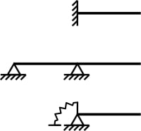
A cantilever beam is a type of structural element which is firmly supported at one end and free at other end. The support may be a flat wall or firmly pinned joint.

A cantilever beam will have a moment and two reaction forces at the fixed end, the free end will have no reaction force acting on it. While solving the problems related to cantilever beams, we apply equilibrium conditions to find the reaction forces and moment.

bending stress example
Image: Cantilever beam diagram
Image credits: Mecanismo at English WikipediaCantilever examplesCC BY-SA 3.0

Examples of cantilever beam

Cantilever beam is nothing but a beam extending from a fixed support to a free end. The examples of cantilever beam are as follows-

  • Bridge under construction.
  • Balconies protruding out of rooms.
  • Building is an example of cantilever with fixed end at ground and free end is the top floor.
  • Wings of an aeroplane.

Cantilever beam bending stress example

Let us assume the following given data for a cantilever beam-

Bending moment, M= 1962 N-mm

Section Modulus, Z= 12mm^3

The bending stress can be given by the formula-

σ = M/Z

Substituting all the values in above formula we get,

Bending stress= 163.5 MPa

Combined axial and bending stress

When both axial stress and bending stress are applied, the system experiences deformation in longitudinal as well as plane normal to the longitudinal plane.

To calculate the combined stress acting on the work piece, following formula is used-

For compressive axial force and bending-

gif

For tensile axial force and bending-

gif

First part of the formula represents axial stress and latter represents bending stress.

Combined axial and bending stress example

Let us assume the following data for a work piece experiencing both axial and bending stress-

Cross section area, A=8000mm^2

Bending moment, M= 12800kN-mm

Section modulus, Z= 266666.67 mm^3

Load, P= 256kN

We calculate the bending stress from the formula given above

Substituting the values we get,

Bending stress= 80 Mpa

What is a simply supported beam?

A simply supported beam is a structural element which is fixed at one and supported at other end by a roller. A roller permits movement in one direction only and restricts movement in another.

Unlike cantilever beams, the simply supported beam has a reaction force acting at the end opposite to fixed end. The examples of simply supported beams include truss structure, bridges etc.

How To Calculate Subcooling: Process, Formula, Work, Example

The subcooling is a valuable process in the refrigeration and HVAC system

It can be obtained by knowing the temperature of the circulating refrigerant and the saturation temperature at the corresponding pressure.

It can be defined as a refrigerant existing at a temperature less than the refrigerant’s boiling point.

It is a valuable process to ensure that the refrigerant passes through the thermal expansion device.

Subcooling formula

The subcooling of a liquid, particularly in the context of refrigeration cycles, is calculated by the formula:

 \text{Subcooling (°F or °C)} = T_{\text{sat}} - T_{\text{ll}}

(Subcooling value = Temperature of saturated liquid – Temperature of liquid line)

Where:

  •  (T_{\text{sat}}) is the temperature of the saturated liquid at a given pressure, measured in degrees Fahrenheit (°F) or Celsius (°C).
  •  (T_{\text{ll}}) is the temperature of the liquid line or the actual temperature of the refrigerant liquid as it exits the condenser, also in °F or °C.

How to Calculate Subcooling

To calculate subcooling in a refrigeration system:

Record the Liquid Temperature:

Using a surface temperature probe, measure the temperature of the liquid refrigerant as it leaves the condenser. This is your liquid line temperature.

Determine the Saturated Liquid Temperature:

Do this by converting the high side pressure at the condenser’s exit into its corresponding saturated liquid temperature. A pressure/temperature chart or comparator specific to your refrigerant type will be required here, as different refrigerants have different pressure-temperature relationships. The resulting saturated temperature is your saturation temperature.

Calculate Subcooling:

Apply this formula:

Subcooling = T_{\text{sat}} - T_{\text{ll}}

Practical Example

Assume that you measure 115°F for the liquid leaving temp (T_{\text{ll}}). Using a pressure/temperature chart, you find that your high side pressure corresponds to a saturated liquid temp (T_{\text{sat}}) of 125°F.

If you plug those values into the formula, you get:

 \text{Subcooling} = 125°F - 115°F = 10°F

So, in this case there is a 10°F subcooling which means that heat is being efficiently removed from your refrigerant by your condenser and fully condensed into its liquid form before it reaches the expansion valve.

How to measure subcooling in HVAC ?

The subcooling can be measured by following the simple steps

  • Obtain steady-state condition for measurement
  • Keep the system run till you get sure about the steady-state condition
  • Attach the thermocouple between the condenser and the expansion valve to measure the temperature of the refrigerant line
  • Note the temperature of the refrigerant line
  • Measure the pressure at the condenser with the pressure measuring instrument (pressure gauge)
  • Find the condenser saturation temperature with the pressure reading with the chart.
  • Find the difference between the condenser saturation temperature and the refrigerant line temperature.
  • The difference between both temperature is the subcooling

The system’s temperature can be measured with various temperature measuring instruments like RTD, Thermocouple and digital thermocouple, etc. The bourdon tube pressure gauge is attached to the system to obtain the pressure. The pressure-temperature chart converts the pressure data into corresponding saturation temperature. The process of subcooling measurement is simple, but accuracy in reading is required to obtain the correct value.

The value of subcooling is helpful to find the many problems situated in the system. If the subcooling value is not proper, then there are chances of the following problems in the system,

  • Insufficient airflow over the condenser tubes
  • Expansion problem associated with an expansion device
  • There is no sufficient refrigerant in the system
  • Troubleshooting

How to calculate subcooling in refrigeration?

The subcooling in the refrigeration can be calculated with the values of temperatures.

It is a difference of two temperatures; one is the temperature of saturated liquid and the temperature of the liquid line.

The subcooling can be calculated with the following equation after measurement of the values with the experiment.

How to calculate subcooling
Subcooling in refrigeration credit Wikipedia

Subcooling value = Temperature of saturated liquid – Temperature of liquid line

The subcooling can be measured in a refrigerator with the following steps:

  • Measure the pressure at the receiver. Measure with the pressure gauge
  • Use the pressure-temperature chart to obtain the value of the saturation temperature of the refrigerant
  • Measure the real temperature of the refrigerant circulating through the condenser. Measure the value at the outlet of the condenser
  • Take the difference between both temperatures. The value of the difference is the value of the subcooling.
  • The value of the subcooling is helpful to find various issues associated with the refrigeration system.

How to calculate target subcooling ?

Target Subcooling is obtained using the target subcooling chart

It can obtain by finding the indoor wet bulb temperature and the outdoor dry bulb temperature.

The meaning of indoor wet-bulb temperature is the measurement of indoor temperature with a thermometer bulb covered with a wet cloth.

The outdoor dry bulb temperature can be measured by placing the thermometer outside the environment. Care should be taken to avoid putting a thermometer in direct sunlight.

The outdoor dry bulb is the outdoor ambient temperature of the air entering the compressor coils. Thermometer placement is essential, keep out of the sun.

Different manufacturer of HVAC system follows different method to calculate target subcooling. They follow their own target subcooling chart to find the target subcooling.

The manufacturer provides the value of target subcooling with the system.

The target subcooling is provided on the rating plate of the system. It is named “TXV Subccoling” on the rating plate. This number of target subcooling is not very high; it is slightly as per the manufacturer.

How to calculate subcooling 410a ?

The equation calculates the subcooling of the refrigerant 410a

Subcooling value of refrigerant R – 410a = Temperature of saturated refrigerant R – 410a – Temperature of liquid line

The calculation method and formula remain the same for every refrigerant. The temperature values are changed according to the nature of the refrigerant.

The refrigerant R410a is a member of the family hydrofluorocarbon.

How to calculate subcooling r22 ?

The equation calculates the subcooling of the refrigerant R22

Subcooling of refrigerant R22 = Temperature of saturated refrigerant R22 – Temperature of liquid line

The measurement of both temperatures can be done by a few steps discussed in the topic above. You can visit the above topic for more detail on practical how-to measure temperature and pressure for calculation.

The chemical name of the R22  is mono chlorofluoromethane

How to calculate subcooling r134a ?

The equation calculates the subcooling of the refrigerant R134a

Subcooling value of refrigerant R134a = Temperature of saturated refrigerant R134a – Temperature of liquid line

The chemical name of the R134a  is 1, 1, 1, 2 – Tetraflouroethane.

Von Mises Stress Vs Principal Stress: Comparative Analysis And Exhaustive FACTS

Von Mises Stress and Principal Stress

The knowledge about Von Mises Stress Vs Principal Stress is highly effective to judge if a mechanical design is within design limits and will work safely during its operation period.

Principal stress on a plane is the maximum stress acts on it and in this case shear stress is measured as zero. Von Mises stress, mostly considered in case of a ductile material is a value used to determine the limit of fracture of a given material.

The equation to calculate Von Mises stress on a mechanical component

V = √(σx2 – (σx * σy) + σy2 + (3 *txy2))

Where V is the Von Mises Stress

σx is the normal stress x component

σy is the normal Stress y component

τxy is the Shear Stress

When a mechanical component is acted upon by 3D loads a very complex three dimensional stress system has developed. The direction and magnitude of stresses are different from point to point. Here Von Mises criterion is a formula for calculating the effect of these combined stresses at a point is responsible for failure or not.

Von Mises Stress Vs Principal Stress

Both Von Mises stress and Principal stress have owm significance in identifying the behaviour of a mechanical or structural component.

The differences between Von Mises and Principal stress are as follows:

Principal StressVon Mises Stress
Principal stress is a real stressA measure of energy density, not a real stress.
Principal stress represents the maximum and minimum of normal stresses on a principal plane at a condition of zero shear stress acts on a body. Von Mises stress is associated with yielding criterion of a ductile material . Von Mises stress is a theoretical measurement and +ve or –ve sign depends on the principal stress.
Failure theory based on Principal stress is applicable to brittle materials like casting components, for example gear box.Failure theory bases on Von Mises is used for ductile materials like aluminium, steel etc.
Not possible to calculate Principal stresses from Von Mises.Possible to calculate Von Mises easily from Principal stresses.

The normal stresses act on a principal plane are called Principal stresses which give the extreme values.If we consider two dimensional stress state of a material major and minor principal stresses will give the extreme values of the normal stresses.

Principal stresses can be obtained by rotating suitably the stress element in such a way that the rotated element does not experience any shear stress.

Engineers most widely use distortion energy theory to predict the failure of a ductile material and this theory also gives the perception of Von Mises stress.

Von Mises stress is not a true stress but a theoretical value which gives a comparison in between general tri dimensional stress and uni axial stress yield limit.

Von MIses stress vs Principal stress
The von Mises yield surfaces in principal stress coordinates circumscribes a cylinder;Image Credit: www.simscale.com

The above figure shows the yield criterion in the principal stress space. Any stress state can be represented by three principal stresses and considering as three coordinates, the various combinations of Von Mises stress may lead to a cylindrical surface.

The failure or yielding of a mechanical component starts at a point if the stress state associated with any point lies on the cylindrical surface.

Can Principal Stress be Greater than Von Mises?

In certain cases, the principal stresses are greater than Von Mises stress.

Von Mises sress can be expressed using the principal stresses acting in different axis as below:

EQ1 1

In certain conditions, principal stresses attains a greater value than the Von Mises stress. If Compression stresses which are acting on principal axes are nearly equal then Von Mises stresses will be very less.

Two types of failure are generally observed in Engineering materials: Brittle failure and Ductile failure.

4 1

For the safe designing of piping and structural beams Von Mises stress theory is applied under various load condition.

The strength of a material is nothing but the necessary stress for breaking the atomic bond and splitting all the atoms of a material.

Ductile materials fail due to yielding and it happens due to the sliding of atoms. The necessary energy to yield is lower than the energy necessary for untying the atomic planes.

When the shear stress of a ductile material reaches its highest value(maximum), the yielding of the ductile material starts.

In case of brittle material the separation of atomic planes lead to failure of the material.

The strain energy density experienced at a point of a material can be expressed in terms of principal stresses as given below:

EQ2 1

The strain energy density observed at a point in a material are mainly due to change in volume(Uh) and due to change in shape (Ud)which are popularly known as  Dilatational and  Distortion strain energy density respectively.

By substracting Uh i.e Dilatational Strain energy density from U0 i.e total energy density we will get Distortion strain energy(Ud) part.

EQ11 1

The expression for Ud in terms of Von Mises stress can be written as below:

EQ12 1

In the above formula, Ud is the distortion energy density and when it reaches a critical value, the yielding of ductile material begins. This idea is given by Von Mises theory.

Since this is generally applicable for an uniaxial stress state, we can easily calculate this critical value of distortional energy from uniaxial test.

Under this condition, the principal stress is given by σ1 = σY(yield stress) and and σ2 = σ3 = 0.

The necessary energy density for yielding is given below:

EQ 13 1

The above expression for energy density gives the the critical value of the distortional energy density for the material.

As per the Von Mises’s failure criterion, When a material is subjected to multiaxial loading, yielding of the material takes place when the distortional energy = or > than the critical value for the material.

EQ14 1

Therefore, the yielding of a material starts when the  Von Mises stresses acting on the material are greater than the yield stress experienced by the material in a uniaxial tensile test.

In terms of stress components Von Mises stress can be written as

EQ15 2

For 2D plane stress state σ3=0, the Von Mises stress in terms of principal stress can be expressed as follows

EQ 16 1
DIA2
Failure envelope of the distortion energy theory;Image Credit: mae.ufl.edu