How To Test Capacitor With A Multimeter & Safety Precaution

how to test a capacitor

Testing a capacitor with a multimeter is a crucial step in troubleshooting electrical circuits. A capacitor stores electrical energy and can fail over time, causing issues in electronic devices. By using a multimeter, you can determine if a capacitor is functioning properly or if it needs to be replaced. In this article, we will explore the steps involved in testing a capacitor with a multimeter, ensuring that you can diagnose and resolve capacitor-related problems effectively.

Key Takeaways:

Test Multimeter Setting Expected Reading
Capacitance Test Capacitance (Farad) Within the specified range
Resistance Test Resistance (Ohm) Continuity or a gradual increase in resistance
Leakage Test Resistance (Ohm) Infinite resistance or a very high value
Polarity Test Diode Test Forward bias reading for electrolytic capacitors
ESR Test Resistance (Ohm) Low resistance reading for good capacitors

Note: The table above provides a concise overview of the different tests and multimeter settings used to test a capacitor.

Key Takeaways

Y4iyd75VCdpYKJjgcjTSJA4bTXitYAblDyzJ0pUPBexWEWJlsKO26da5Y4OJ5ygFD0y2gB qtaCZki0XBqpNZ o1DfHdv1VVGdcIrojYUUaDCUzw ObOCIzvuLrmXBC c8ycEYabF3RXGd RXwOoy4E

[]

When it comes to testing capacitors, using a multimeter can be a valuable tool. By following a few simple steps, you can effectively measure the capacitance and check the health of a capacitor without the need for desoldering or removing it from the circuit. In this guide, we will explore the process of testing capacitors using a multimeter, covering everything from the basic setup to interpreting the readings.

To begin testing a capacitor, you will need a multimeter capable of measuring capacitance. Both digital and analog multimeters can be used for this purpose. Once you have the necessary equipment, follow these steps:

  1. Disconnect the capacitor: Before testing, ensure that the capacitor is disconnected from any power source or circuit to prevent any interference or potential damage.

  2. Set the multimeter: Adjust the multimeter settings to the capacitance measurement mode. This mode is usually denoted by a symbol resembling a series of parallel lines or the letter “F” for farads.

  3. Connect the multimeter probes: Connect the multimeter probes to the corresponding terminals of the capacitor. The positive probe should be connected to the positive terminal, and the negative probe to the negative terminal.

  4. Read the multimeter: Once the probes are connected, the multimeter will display the capacitance value of the capacitor. This reading indicates the amount of charge the capacitor can store.

    • If the multimeter displays a value close to the labeled capacitance value of the capacitor, it indicates that the capacitor is in good health.

    • If the multimeter shows a reading of zero or infinity, it suggests that the capacitor is faulty and needs to be replaced.

    • A significant rise in resistance during the test can also indicate a faulty capacitor.

    • In some cases, the multimeter may display a very low capacitance value or no reading at all. This could be due to a short circuit or a capacitor that has lost its capacitance over time.

  5. Discharge the capacitor: After testing, it is essential to discharge the capacitor to ensure safety and prevent any residual charge. This can be done by connecting a resistor across the capacitor terminals or using the discharge function on the multimeter if available.

Remember, when testing electrolytic capacitors, it is crucial to observe the polarity. Connecting the multimeter probes incorrectly can cause damage to the capacitor or even lead to its failure. Additionally, always release any pressure built up in the capacitor before testing, as it can affect the accuracy of the readings.

By following these steps and understanding the readings obtained from the multimeter, you can effectively test capacitors and verify their health without the need for specialized equipment. Regularly checking the condition of capacitors in your circuits can help prevent potential failures and ensure the smooth operation of your electronic devices.

Understanding Capacitors and Multimeters

What is a Capacitor?

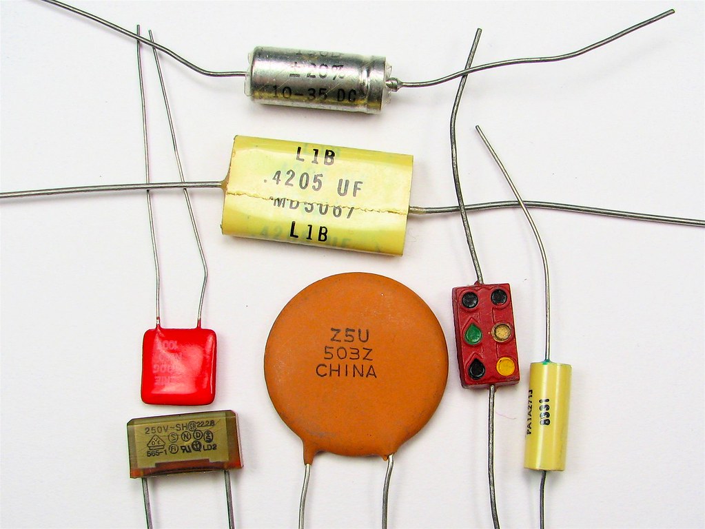
A capacitor is an electronic component that stores and releases electrical energy. It consists of two conductive plates separated by an insulating material called a dielectric. When a voltage is applied across the plates, the capacitor charges up, storing energy. This stored energy can be released when needed, making capacitors useful in a wide range of electronic circuits.

Capacitors are commonly used in various applications, such as filtering out noise in power supplies, smoothing voltage fluctuations, and storing energy in flash cameras. They come in different types, including electrolytic capacitors, ceramic capacitors, and tantalum capacitors, each with its own characteristics and uses.

To ensure the proper functioning of a capacitor, it is important to test it regularly. Testing a capacitor can help identify faulty components and prevent potential circuit failures. There are several signs that indicate a faulty capacitor, such as bulging or leaking, a burnt smell, or a capacitor that fails to hold a charge. By testing capacitors, you can verify their health and avoid potential issues in your electronic devices.

Capacitor Testing Guide

When testing a capacitor, a multimeter is a handy tool to have. A multimeter is a versatile device used for measuring various electrical quantities, including voltage, current, and resistance. It can also be used to test capacitors and determine their values.

What is a Multimeter?

A multimeter, also known as a volt-ohm meter (VOM), is an essential tool for any electronics enthusiast or professional. It combines several measurement functions into a single device, making it convenient for troubleshooting and testing electronic circuits.

There are two main types of multimeters: digital multimeters (DMM) and analog multimeters. Digital multimeters provide precise measurements and are easier to read, while analog multimeters use a needle to indicate values and are better for observing changes in readings over time.

Multimeter Usage

To test a capacitor using a multimeter, you need to set the multimeter to the appropriate settings. The specific settings may vary depending on the type of multimeter you have, but generally, you will need to select the capacitance measurement function.

To begin the test, disconnect the capacitor from the circuit and discharge it to ensure your safety. Then, connect the multimeter probes to the capacitor terminals, making sure to connect the positive probe to the positive terminal and the negative probe to the negative terminal.

Multimeter Settings for Capacitor Testing

When using a multimeter to test a capacitor, it is important to set the multimeter to the correct range. Start with the highest range and gradually decrease it until you get a reading. This will ensure accurate measurements and prevent damage to the multimeter.

When testing capacitors, the multimeter will display the capacitance value in microfarads (µF). If the multimeter reading shows zero or infinity, it indicates a faulty capacitor that needs to be replaced. A good capacitor should have a stable reading close to its rated value.

Testing Capacitors Without Desoldering

In some cases, you may want to test a capacitor without desoldering it from the circuit. This can be done by using the multimeter’s continuity test or resistance measurement function.

To test continuity, set the multimeter to the continuity mode and touch the probes to the capacitor terminals. If the multimeter beeps or shows a low resistance value, it indicates that the capacitor is shorted and needs to be replaced.

To test resistance, set the multimeter to the resistance measurement mode and connect the probes to the capacitor terminals. A good capacitor should show a high resistance value that gradually rises and then stabilizes. If the resistance value is too low or does not rise, it indicates a faulty capacitor.

Remember to always discharge a capacitor before testing it to release any stored electrical energy and prevent potential accidents. Additionally, be cautious when handling capacitors, as they can store a charge even when disconnected from a power source.

By understanding how capacitors work and using a multimeter effectively, you can ensure the proper functioning of electronic components and troubleshoot circuit issues with ease. Regular testing and maintenance of capacitors can help prevent failures and ensure the longevity of your electronic devices.

General Steps to Test a Capacitor with a Multimeter

Testing a capacitor with a multimeter is a crucial step in diagnosing faulty electronic components. By following a few general steps, you can determine the health and functionality of a capacitor. Let’s walk through the process together.

Discharging the Capacitor

Before testing a capacitor, it is essential to discharge it to ensure your safety. Capacitors store electrical energy, and if not discharged properly, they can give you an unpleasant shock. To discharge a capacitor, you can use a resistor or a short wire to create a safe path for the stored charge to dissipate.

Setting up the Multimeter

To begin the testing process, you need to set up your multimeter correctly. Whether you are using a digital or analog multimeter, ensure that it is set to the appropriate settings for capacitance measurement. Refer to the user manual of your multimeter to determine the specific settings required.

Connecting the Multimeter Probes

Next, you need to connect the multimeter probes to the capacitor. Identify the positive and negative terminals of the capacitor. The positive terminal is usually marked with a “+” symbol, while the negative terminal is marked with a “-” symbol. Connect the positive probe of the multimeter to the positive terminal of the capacitor and the negative probe to the negative terminal.

Measuring the Capacitance

Once the multimeter is properly connected to the capacitor, you can proceed to measure the capacitance. Activate the capacitance measurement function on your multimeter and observe the reading. The multimeter will display the capacitance value in microfarads (μF) or picofarads (pF), depending on the range of your multimeter.

Checking for Proper Charging and Discharging

In addition to measuring the capacitance, it is important to check if the capacitor charges and discharges properly. To do this, you can use the multimeter’s voltage measurement function. Connect the multimeter probes to the capacitor terminals as before and observe the voltage reading. A healthy capacitor should charge and discharge smoothly, with the voltage rising and falling accordingly.

Interpreting the Results

After performing the measurements and observations, it’s time to interpret the results. If the multimeter displays a capacitance value within the expected range for the specific capacitor, it indicates that the capacitor is functioning correctly. However, if the capacitance value is significantly lower or higher than the expected range, it may indicate a faulty capacitor.

Remember, testing a capacitor without desoldering it from the circuit can provide a general idea of its health. However, for a more accurate assessment, it is recommended to remove the capacitor from the circuit and test it individually.

By following these general steps, you can effectively test a capacitor using a multimeter. It is an essential skill for any electronics enthusiast or technician, allowing you to identify faulty capacitors and ensure the proper functioning of electronic devices.

Specific Capacitor Testing Procedures

Capacitors are essential electronic components used in various circuits to store and release electrical energy. Over time, capacitors can degrade or fail, leading to circuit malfunctions. Therefore, it is crucial to test capacitors regularly to ensure their proper functioning. In this guide, we will explore different methods to test capacitors using a multimeter, catering to specific scenarios and equipment.

How to Test a Guitar Capacitor with a Multimeter

When it comes to testing a guitar capacitor, a multimeter can be a handy tool. Follow these steps to check the health of your guitar capacitor:

  1. Disconnect the guitar from any power source and remove the back cover to access the electronics.
  2. Set your multimeter to the capacitance measurement mode.
  3. Identify the capacitor in the circuit and locate its terminals.
  4. Connect the multimeter probes to the capacitor terminals, ensuring the positive probe is connected to the positive terminal and the negative probe to the negative terminal.
  5. Read the capacitance value displayed on the multimeter. Compare it to the expected value specified by the manufacturer. If the readings deviate significantly, the capacitor may be faulty and should be replaced.

How to Test a Capacitor with a Multimeter HVAC

In HVAC systems, capacitors play a crucial role in the operation of motors and compressors. To test a capacitor in an HVAC system using a multimeter, follow these steps:

  1. Turn off the power supply to the HVAC system and discharge any stored energy in the capacitor by shorting its terminals with an insulated screwdriver.
  2. Set your multimeter to the capacitance measurement mode.
  3. Identify the capacitor in the HVAC circuit and locate its terminals.
  4. Connect the multimeter probes to the capacitor terminals, ensuring the positive probe is connected to the positive terminal and the negative probe to the negative terminal.
  5. Read the capacitance value displayed on the multimeter. Compare it to the expected value specified by the manufacturer. If the readings deviate significantly, the capacitor may be faulty and should be replaced.

How to Test a Microwave Capacitor with a Multimeter

Microwave ovens utilize capacitors to store and discharge high voltage energy. To test a microwave capacitor using a multimeter, follow these steps:

  1. Ensure the microwave oven is unplugged and discharge any stored energy in the capacitor by shorting its terminals with an insulated screwdriver.
  2. Set your multimeter to the capacitance measurement mode.
  3. Locate the capacitor in the microwave circuit and identify its terminals.
  4. Connect the multimeter probes to the capacitor terminals, ensuring the positive probe is connected to the positive terminal and the negative probe to the negative terminal.
  5. Read the capacitance value displayed on the multimeter. Compare it to the expected value specified by the manufacturer. If the readings deviate significantly, the capacitor may be faulty and should be replaced.

How to Test a Capacitor with a Klein Multimeter

Klein multimeters are versatile tools that can be used to test capacitors in various electronic circuits. Follow these steps to test a capacitor using a Klein multimeter:

  1. Set your Klein multimeter to the capacitance measurement mode.
  2. Identify the capacitor in the circuit and locate its terminals.
  3. Connect the multimeter probes to the capacitor terminals, ensuring the positive probe is connected to the positive terminal and the negative probe to the negative terminal.
  4. Read the capacitance value displayed on the multimeter. Compare it to the expected value specified by the manufacturer. If the readings deviate significantly, the capacitor may be faulty and should be replaced.

How to Test a Fan Capacitor with a Multimeter

Fan capacitors are commonly found in ceiling fans and other motor-driven fans. To test a fan capacitor using a multimeter, follow these steps:

  1. Turn off the power supply to the fan and discharge any stored energy in the capacitor by shorting its terminals with an insulated screwdriver.
  2. Set your multimeter to the capacitance measurement mode.
  3. Locate the capacitor in the fan circuit and identify its terminals.
  4. Connect the multimeter probes to the capacitor terminals, ensuring the positive probe is connected to the positive terminal and the negative probe to the negative terminal.
  5. Read the capacitance value displayed on the multimeter. Compare it to the expected value specified by the manufacturer. If the readings deviate significantly, the capacitor may be faulty and should be replaced.

How to Test a Furnace Capacitor with a Multimeter

Furnace capacitors are critical components in heating systems. To test a furnace capacitor using a multimeter, follow these steps:

  1. Turn off the power supply to the furnace and discharge any stored energy in the capacitor by shorting its terminals with an insulated screwdriver.
  2. Set your multimeter to the capacitance measurement mode.
  3. Locate the capacitor in the furnace circuit and identify its terminals.
  4. Connect the multimeter probes to the capacitor terminals, ensuring the positive probe is connected to the positive terminal and the negative probe to the negative terminal.
  5. Read the capacitance value displayed on the multimeter. Compare it to the expected value specified by the manufacturer. If the readings deviate significantly, the capacitor may be faulty and should be replaced.

How to Test a Generator Capacitor with a Multimeter

Generators rely on capacitors for smooth power generation. To test a generator capacitor using a multimeter, follow these steps:

  1. Turn off the generator and discharge any stored energy in the capacitor by shorting its terminals with an insulated screwdriver.
  2. Set your multimeter to the capacitance measurement mode.
  3. Locate the capacitor in the generator circuit and identify its terminals.
  4. Connect the multimeter probes to the capacitor terminals, ensuring the positive probe is connected to the positive terminal and the negative probe to the negative terminal.
  5. Read the capacitance value displayed on the multimeter. Compare it to the expected value specified by the manufacturer. If the readings deviate significantly, the capacitor may be faulty and should be replaced.

How to Test a Bad Capacitor with a Multimeter

If you suspect a capacitor to be faulty, you can perform a simple test using a multimeter. Follow these steps to test a potentially bad capacitor:

  1. Set your multimeter to the resistance or continuity mode.
  2. Discharge the capacitor by shorting its terminals with an insulated screwdriver.
  3. Connect the multimeter probes to the capacitor terminals, ensuring the positive probe is connected to the positive terminal and the negative probe to the negative terminal.
  4. Observe the multimeter reading. A good capacitor should initially show zero resistance or continuity and then gradually rise to infinity. If the reading remains constant or shows zero resistance, the capacitor may be faulty and should be replaced.

By following these specific capacitor testing procedures, you can effectively diagnose and identify faulty capacitors in various electronic circuits. Regular testing and maintenance of capacitors will help ensure the proper functioning of your electronic devices and prevent potential circuit failures. Remember to always exercise caution and follow safety guidelines when working with electrical components.

How to Test a Motor Capacitor with a Multimeter

How to Test a Capacitor with a Fluke Multimeter

Testing a motor capacitor is an essential step in troubleshooting electrical equipment. A faulty capacitor can cause various issues, such as motor failure or erratic behavior. By using a multimeter, you can easily check the health of a capacitor and determine if it needs to be replaced. In this guide, we will focus on how to test a capacitor with a Fluke multimeter, a popular and reliable brand known for its accuracy and versatility.

Before we dive into the testing process, let’s briefly understand what a capacitor is and its role in an electrical circuit. A capacitor is an electronic component that stores electrical energy. It consists of two conductive plates separated by an insulating material called a dielectric. Capacitors are commonly used in motors to provide an extra boost of power during startup or to smooth out voltage fluctuations.

To test a capacitor with a Fluke multimeter, you will need to follow a few simple steps. Here’s a step-by-step guide:

  1. Ensure Safety: Before starting any electrical measurements, make sure to disconnect the power source and discharge the capacitor to avoid any potential electrical shocks. Safety should always be a top priority.

  2. Select the Correct Multimeter Setting: Set your Fluke multimeter to the capacitance measurement mode. This mode allows you to measure the capacitance value of the capacitor accurately. Refer to your multimeter’s user manual if you are unsure how to change the settings.

  3. Connect the Multimeter Probes: Take the multimeter probes and connect the positive (red) probe to the positive terminal of the capacitor. Similarly, connect the negative (black) probe to the negative terminal of the capacitor. Ensure a secure and proper connection to obtain accurate readings.

  4. Read the Multimeter Display: Once the probes are connected, the multimeter will display the capacitance value of the capacitor. Compare this reading with the expected value specified by the manufacturer. If the measured value is significantly different or close to zero, it indicates a faulty capacitor that needs to be replaced.

It’s important to note that not all multimeters have a dedicated capacitance measurement mode. In such cases, you can use the resistance (ohm) measurement mode to test the capacitor indirectly. Follow these steps:

  1. Discharge the Capacitor: Before proceeding, discharge the capacitor by shorting its terminals with a resistor or using the discharge function on your multimeter. This step ensures your safety and prevents any residual charge from interfering with the test.

  2. Connect the Multimeter Probes: Set your multimeter to the resistance (ohm) measurement mode. Connect the positive probe to the positive terminal of the capacitor and the negative probe to the negative terminal. Make sure the connections are secure.

  3. Observe the Multimeter Reading: The multimeter will display a resistance value. A good capacitor will initially show a low resistance reading, which should then rise gradually and eventually stabilize. If the resistance remains at zero or infinity, it indicates a faulty capacitor that needs to be replaced.

By following these steps, you can effectively test a motor capacitor using a Fluke multimeter. Remember to always refer to the manufacturer’s specifications for the expected capacitance value and consult a professional if you are unsure about any electrical measurements or procedures. Regularly testing and verifying the health of capacitors in your electrical circuits can help prevent potential failures and ensure the smooth operation of your equipment.

Using Online Resources

How to Test a Capacitor with a Multimeter YouTube

When it comes to testing capacitors, online resources can be incredibly helpful. One such resource is a YouTube video titled “How to Test a Capacitor with a Multimeter.” This video provides a step-by-step guide on how to test a capacitor using a multimeter, making it easier for beginners to understand the process.

In the video, the presenter explains the importance of capacitor testing and demonstrates how to perform the test using a multimeter. They cover various aspects, including multimeter settings for capacitor testing, different types of multimeters (digital and analog), and the correct way to connect the multimeter probes to the capacitor terminals.

To ensure that the video remains relevant and coherent, the presenter emphasizes the significance of understanding capacitor health and the signs of a faulty capacitor. They also explain how to discharge a capacitor safely before testing and provide tips on interpreting the multimeter readings.

One of the key takeaways from the video is the importance of checking the capacitor’s value. The presenter explains how to verify the capacitor’s value using the multimeter and discusses the significance of capacitance measurement in electronic component testing.

The video also covers the testing of electrolytic capacitors, microfarad readings, and non-polarized capacitor testing. Additionally, the presenter explains how voltage measurement can be a factor in capacitor failure and how excessive pressure can cause a capacitor to fail.

To determine the health of a capacitor, the video suggests testing for zero or infinity resistance and observing the rise in resistance over time. By using the multimeter’s terminals and connecting them to the capacitor in the circuit, users can effectively test the capacitor’s functionality.

Overall, the “How to Test a Capacitor with a Multimeter” YouTube video provides a comprehensive guide for DIY enthusiasts and beginners alike. It offers valuable insights into capacitor testing, multimeter usage, and electrical measurements. By following the instructions in the video, users can gain confidence in testing capacitors and troubleshooting circuit issues.

Frequently Asked Questions

Can I test a capacitor with a multimeter using YouTube tutorials?

Yes, you can definitely use YouTube tutorials as a helpful resource to learn how to test a capacitor with a multimeter. Many experienced individuals and experts share their knowledge and techniques through video tutorials, making it easier for beginners to understand the process. These tutorials often provide step-by-step instructions, demonstrations, and tips to ensure accurate testing. However, it is important to note that not all tutorials may be reliable or accurate, so it’s essential to cross-reference information and follow trusted sources.

How do I test a capacitor with a multimeter in a circuit board?

Testing a capacitor with a multimeter while it is still in a circuit board requires a slightly different approach. Here’s a step-by-step guide to help you:

  1. Safety First: Before starting any testing, ensure that the circuit board is powered off and disconnected from any power source.
  2. Discharge the Capacitor: To discharge the capacitor, use a resistor or a screwdriver with an insulated handle to bridge the capacitor’s terminals. This will prevent any residual charge from causing damage or giving inaccurate readings.
  3. Set the Multimeter: Set your multimeter to the capacitance measurement mode (usually denoted by the symbol “F” for Farads). If your multimeter doesn’t have a dedicated capacitance mode, you can use the resistance mode.
  4. Connect the Multimeter: Connect the multimeter probes to the capacitor terminals. Ensure that the positive probe is connected to the positive terminal of the capacitor and the negative probe to the negative terminal.
  5. Read the Value: The multimeter will display the capacitance value of the capacitor. Compare this reading to the expected value specified on the capacitor or in the circuit’s documentation. If the reading deviates significantly from the expected value, it may indicate a faulty capacitor.

Can you test a capacitor with a digital multimeter?

Yes, you can test a capacitor with a digital multimeter. Digital multimeters are versatile tools that offer various measurement modes, including capacitance measurement. To test a capacitor with a digital multimeter, follow these steps:

  1. Set the Multimeter: Set your digital multimeter to the capacitance measurement mode (usually denoted by the symbol “F” for Farads).
  2. Connect the Multimeter: Connect the multimeter probes to the capacitor terminals. Ensure that the positive probe is connected to the positive terminal of the capacitor and the negative probe to the negative terminal.
  3. Read the Value: The digital multimeter will display the capacitance value of the capacitor. Compare this reading to the expected value specified on the capacitor or in the circuit’s documentation. If the reading deviates significantly from the expected value, it may indicate a faulty capacitor.

How to test a capacitor without a multimeter?

If you don’t have a multimeter available, there are alternative methods to test a capacitor. Here are a couple of techniques you can try:

  1. Using a Battery: To test a capacitor without a multimeter, you can use a battery (such as a 9V battery) and a resistor. Connect the positive terminal of the battery to the positive terminal of the capacitor and the negative terminal of the battery to one lead of the resistor. Connect the other lead of the resistor to the negative terminal of the capacitor. If the capacitor is functioning properly, you may observe a brief spark when connecting the resistor. However, this method only provides a basic indication of the capacitor’s health and does not provide an accurate capacitance value.
  2. Visual Inspection: Another way to test a capacitor without a multimeter is through visual inspection. Examine the capacitor for any physical signs of damage, such as bulging, leaking, or a burnt smell. These signs often indicate a faulty capacitor that needs replacement.

Remember, while these alternative methods can provide some insight into the capacitor’s condition, they may not be as accurate or reliable as using a multimeter.

Testing a capacitor with a multimeter is a simple and effective way to determine its health and functionality. By following the steps outlined in this guide, you can easily check if a capacitor is working properly or if it needs to be replaced. Remember to always discharge the capacitor before testing to ensure your safety. Multimeters provide accurate readings of capacitance, resistance, and voltage, allowing you to identify any issues with the capacitor. Regularly testing your capacitors can help prevent unexpected failures and ensure the smooth operation of your electronic devices.

Frequently Asked Questions

Q1: What is the simple method to test a capacitor with a multimeter?

A: A simple method to test a capacitor with a multimeter involves setting the multimeter to the capacitance mode, connecting the probes to the capacitor terminals, and reading the measurement on the screen. This should give you the capacitance value in microfarads.

Q2: How can I use a voltmeter to test a capacitor?

A: To use a voltmeter to test a capacitor, first, ensure the capacitor is discharged. Connect the voltmeter across the capacitor terminals and observe the reading. A good capacitor will initially show a low resistance, and then it will gradually increase as the capacitor charges.

Q3: Can I visually check the health of a capacitor?

A: Yes, you can visually check a capacitor for signs of failure. Look for bulging, leakage, or any signs of physical damage. However, not all faulty capacitors show physical signs, so electrical testing with a multimeter is recommended.

Q4: How do I use the continuity mode of a multimeter to test a capacitor?

A: To use the continuity mode of a multimeter to test a capacitor, first, ensure the capacitor is discharged. Then, set the multimeter to continuity mode and connect the probes to the capacitor terminals. A good capacitor will not show continuity.

Q5: What is the time constant parameter to consider while testing a capacitor?

A: The time constant of a capacitor is the product of the resistance and capacitance (RC). It is the time it takes for the voltage across the capacitor to reach approximately 63% of its final value after a step change in voltage. This parameter can be useful in diagnosing a faulty capacitor.

Q6: How to test a capacitor without a multimeter?

A: A traditional method to test a capacitor without a multimeter is to charge the capacitor with a known voltage, then disconnect it and connect it to a resistor. By measuring the time it takes for the voltage to drop to 37% of its original value, you can calculate the capacitance.

Q7: What tools are required to test a capacitor?

A: The primary tool required to test a capacitor is a multimeter with a capacitance mode. Other tools can include a voltmeter, a resistor for the traditional method, and safety equipment like gloves and goggles.

Q8: How to test a capacitor in a circuit board with a multimeter?

A: To test a capacitor in a circuit board with a multimeter, it’s best to disconnect one terminal of the capacitor from the circuit to avoid false readings from other components. Then, set the multimeter to capacitance mode and measure the capacitance as usual.

Q9: What are the signs of a faulty capacitor?

A: Signs of a faulty capacitor can include a bulging or leaking case, a high or low capacitance reading on a multimeter, no continuity on a multimeter, or a high ESR (Equivalent Series Resistance) value.

Q10: How to test an electrolytic capacitor with a multimeter?

A: To test an electrolytic capacitor with a multimeter, set the multimeter to capacitance mode and connect the probes to the capacitor terminals, ensuring the correct polarity. The reading should be close to the rated capacitance. If it’s significantly off, the capacitor may be faulty.

Chiller Work: 7 Important Facts You Should Know

1024px Kompresors.svg 300x192 1

Chillers are machines used to dehumidify or cool fluids. There are various types of chillers classified on the basis of working fluid used, working mechanism used etc.

This article explains how does a chiller work, different types of chillers used in industry and general information about compressors used in air cooled chillers.

How does an air-cooled chiller work?

Ever seen multiple fans installed on the top of a building? They are used for cooling purposes inside the building. These fans are a part of a bigger system known as air cooled chiller.

Chiller is a machine that absorbs heat using vapour compression cycle, vapour absorption cycle or vapour adsorption cycle. The cool fluid can be passed through a heat exchanger for further applications. Concepts of thermodynamics are used in air cooled chillers to cool the fluid or dehumidify air.

Chillers collects heat from water and sends it back to air handling unit which uses cool water for its operation. After AHU’s operation, the water temperature rises and is brought back to the air chiller.

How does an industrial chiller work?

The main purpose of industrial air chiller is to cool the water and send it back to the AHU (Air Handling Unit). After AHU does its specified task, the water inside the AHU becomes warm. This warm water is sent back to the inlet of chiller. This cycle continues till the end of AHU’s operation.

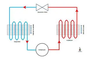
The air chiller absorbs heat from the processed water that comes into the inlet of the chiller. Heat is absorbed with the help of chiller’s evaporator.

After the liquid refrigerant passes through evaporator, its phase changes to gas and pressure decreases in this process. After compression, the refrigerant that leaves has high pressure and high temperature.

This gas enters the condenser where it is cooled by condensing fans. The cooling fans blow away the heat into ambient hence it is suggested to install air chillers outside the room or at a place where dumping heat is not an issue.

An industrial air chiller has following components- Evaporator, condenser, compressor, pump and cooling fans.

  • Evaporator-It takes away heat from the water to change the phase from liquid to gas.
  • Compressor-Temperature and pressure of the gas is increased by compressing the gas in compressor.
  • Condensing fans/cooling fans-The cooling fans blow away the heat from the refrigerant reducing the temperature of gas.
  • Condenser-The phase changes back to liquid inside the condenser.

What are industrial chillers used for?

Industrial chillers are used for cooling mechanisms, products and a wide range of machinery. It can be centralized where one chiller can be used for multiple applications or decentralized where each and every application has one dedicated chiller.

Chillers are used in plastic industries, metal cutting work oils, injection and blow moulding, cement processing. They are also used in gas turbine cooling system, high heat applications such as MRI and lasers in hospitals.

Liquid cooled chillers are used for indoor operations due to as liquid absorbs the rejected heat. Air cooled chillers are meant for outdoor installations because the heat is rejected in the ambient. Hence, most air cooled chillers are installed at the top of buildings.

Types of compressors used in air cooled chillers

There are various types of compressors that can be used in chillers depending on the load requirements in the application. Following are the compressors that can be used in chillers-

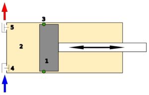
  • Reciprocating compressor-A simple positive displacement pump which used a piston to deliver gas at high pressure. The gas enters the cylinder in the suction stroke when the piston is at bottom dead centre. The gas is compressed in the next stroke when the piston move towards the top dead centre. Compressed gas leaves through the delivery valve. This type of compressors deliver compressed gas in pulsations.
  • Rotary screw compressor-Rotary compressors are used in large sized refrigeration applications such as chillers. These have rotary type positive displacement mechanism and provide continuous delivery of compressed gas unlike reciprocating compressors which have pulsations. Rotary compressors are more quiet in operation.  
  • Vane compressor-Most common type of compressor is the vane compressor. It uses centrifugal force to compress the gas. These compressors uses vanes instead of helical screws to generate compressed air.
  • Scroll compressor-A scroll compressor uses two spiraled scrolls for compressing the gas or refrigerant. Usually one scroll is fixed and other orbits with a little offset without rotating. The tapped gas between the scrolls get compressed due to the relative motion between scrolls. Its efficiency is slightly higher than reciprocating compressors.
how does a chiller work
Image: Reciprocating compressor
Image credit: No machine-KompresorsCC BY-SA 3.0

Water cooled chillers

As the name suggests, water cooled chillers use water instead of air for cooling. It uses latent heat for cooling purposes.

External cooling towers supply water that is used to cool the gaseous refrigerant in the condenser. Inside the condenser, refrigerant’s phase changes. The gaseous refrigerant turns into liquid refrigerant and is then re-circulated in the system.

Advantages and disadvantages of water cooled chillers

Every mechanical component has its own pros and cons. Designers have to make a trade off between pros and cons to make the best design suitable for the particular application. Following are the advantages and disadvantages of water cooled chillers

Advantages of water cooled chillers-

  • They are more efficient than air chilled coolers.
  • They don’t create much noise while operating.
  • They can be used in both small scale and commercial scale applications.

Disadvantages of water cooled chillers-

  • Due to continuous requirement of water, water cooled chillers are not feasible to use in areas having water shortage problems.
  • As the number of components are increased (cooling tower and pumps), installation cost of water cooled chillers is more.

Vapour compressed chillers vs vapour absorbed chillers

Vapour compressed and vapour absorbed chillers are both air cooled chillers. The principle difference between vapour compressed chiller and vapour absorbed air chiller is the way of cooling.

Vapour compressed chillers Vapour absorbed chillers
Vapour compressor chillers use following components- evaporator, condenser, compressor and an expansion unit. Refrigerant extracts unwanted heat, this refrigerant is pumped by the action of compressor. Vapour absorption chillers use same components as vapour compressed chillers except compressor. Instead of compressor, there is an absorber, generator and a pump. Heat source itself is used to pump refrigerant around the system for cooling purposes.
Table: Difference between vapour compressed chillers and vapour absorbed chillers

It is clear that vapour absorbed chiller has more parts but it is cheaper to operate as it does not need any compressed air for operation.

Convert Step Down To Step Up Transformer: 5 Important Facts

We can convert the step-down transformer to a step-up transformer by simply swapping the primary and the secondary windings. We shall now discuss the technique on How To Convert Step Down To Step Up Transformer along with some relevant frequently asked questions in detail.

A step-down transformer implies that it has fewer turns in its secondary coil than its primary coil. If we connect the transformer in a reverse manner, the primary coil becomes secondary, and the secondary coil becomes primary. Therefore, the behaviour of the transformer becomes analogous to that of a step-up transformer. 

How To Convert Step Down To Step Up Transformer- Related Topics

How To Convert Step Down To Step Up Transformer

Step-up transformer – working principle and diagram

A step-up transformer is said to be an electrical apparatus that enlarges the voltage from the primary coil to the secondary coil. It is generally used in power plants where voltage generation and transmission take place. 

 A step-up transformer has two major parts- the core and the windings. The core of the transformer is built with a material having permeability higher than the vacuum. The reason behind using a highly permeable substance is to restrict the magnetic field lines and reduce the losses. Silicon steel or ferrite is used to prevent the transformer from excess eddy current and hysteresis loss. So, the magnetic flux can easily flow through the core, and the efficiency of the transformer increases. 

The transformer windings are fabricated with copper. Copper has huge rigidity and is perfectly suited for carrying a large amount of current. These are covered with insulators to provide safety and endurance for better performance. The windings are coiled over the transformer core. The primary coil consists of fewer windings with thicker wires, specifically designed to carry low voltage and high current. The exact opposite phenomenon takes place for the secondary coil. The wires are thinner this time with more turns. These wires are good carrers of substantial voltage and small current. 

The primary winding is composed of fewer turns than the secondary winding. So, Ns>Np where,

Ns=number of turns in the secondary coil.

Np=number of turns in the primary coil

We know from the properties of an ideal transformer,

Np/Ns=Vp/Vs

Therefore, the more the number of turns in the secondary coil, the more the induced voltage.

But the power should be fixed for a transformer. Therefore, the step-up transformer steps the voltage up and reduces the current so that the power remains unchanged. 

Step-up transformers are an integral part of power systems. Transmission lines use step-up transformers to transfer voltage through long distances. The voltage produced in power plants steps up, transmits through them, and reaches the domestic systems. A step-down transformer lowers the voltage and makes it safe to use in households.

Step-up transformer coil
Step-up transformer winding

Step-down transformer – working principle and diagram 

An electrical device that brings down the voltage from the primary winding to the secondary winding is known as a step-down transformer. The function of a step-down transformer is exactly opposite to the operation of a step-up transformer. 

A step-down transformer core is typically made up of soft iron. The construction is similar to that of the step-up transformer—the ferromagnetic properties of the core help in magnetization and energy transfer. 

The insulator-covered copper wires are employed for the inductor coils. The primary coil is joined with a voltage source, and the secondary coil is joined with the load resistance. The voltage provided as input to the primary coil generates magnetic flux and induces EMF in the secondary coil. The load connected to the secondary coil draws required a “stepped down” alternating voltage. 

We know, in a step-down transformer, the number of turns in the primary winding is more than the number of turns in the secondary winding. So, Np>Ns where,

Ns=number of turns in the secondary coil

Np=number of turns in the primary coil

We know, Np/Ns=Vp/Vs

Therefore, Vs = (Np/Ns) x Vp

As the ratio Ns/Np<1 , Vs<Vp. So, we can conclude that the step-down transformer reduces the voltage.

Just like the step-up transformer, the power is kept constant in the case of the step-down transformer as well. As the voltage level drops, the current at the secondary coil is increased to maintain the balance. 

For houses or other distribution systems, step-down transformers are an essential component.

A 9Py7o9oMgempNnNLH
Step-down transformer winding

How To Convert Step Down To Step Up Transformer-FAQs

What are the differences between a step-up and a step-down transformer?

Step-up transformer Step-down transformer 
A step-up transformer steps the primary voltage up to the secondary coil.A step-down transformer steps the primary voltage down to the secondary coil.
The quantity of turns within the secondary inductor coil of a step-up transformer is higher than the quantity of turns within the primary inductor coil.The quantity of turns within the primary inductor coil of a step-up transformer is higher than the quantity of turns inside the secondary inductor coil.
The value of the output voltage is greater than the input voltage value.The value of the output voltage is lower than the input voltage value.
Thick copper wires are used in primary and thin wires are used in the secondary winding.Thin copper wires are used in primary and thick wires are used in the secondary winding.
Step-up transformers are essential components of electrical substations, power plants etc.Step-down transformers are essential components of distribution systems, adapters, CD players etc.
Transformer Power-Line Electricity - Free photo on Pixabay
Transmission lines make use of step-up transformer

How to use a step-down transformer as a step-up transformer?

A step-down transformer can sufficiently work as a step-up transformer by reversing the operation.

The voltage source and the load resistor are attached to the primary winding and the secondary winding in case of a step-down transformer, respectively. If we power the secondary winding with the voltage and connect the load to the primary winding, the secondary coil acts as primary and vice-versa. So we can say, now the step-down transformer behaves as a step-up transformer and produces an elevated voltage at the secondary coil.

If a step-down Transformer is connected with its output and input interchanged, does it work as a step-up transformer?

It is possible to interchange the input and the output of a step-down transformer to make it work like a step-up transformer.

While we can perform this reverse operation, we have to keep in mind that it is good for temporary uses. We must maintain the original transformer ratings; otherwise, serious hazards may occur. 

What are the conditions while converting a step-down to a step-up transformer?

There are some points that we need to remember when we are going to use a step-down transformer as a step-up transformer. 

  • Theoretically, this method looks easy and plausible. In reality, it is a challenging job and has limitations. When we’re connecting the transformer backward, we change polarity, but the number of turns remains the same as previous. So the turns ratio also doesn’t change. Therefore, the voltage level must be increased in order to keep everything balanced. Let us take an example. Suppose we have a step-down transformer that yields 100 Volt secondary voltage when 200 Volt input voltage is supplied. Turns ratio, Np/Ns= Vp/Vs = 200/100= 2. If we want to use the transformer as a step-up, the same 200-volt input voltage will produce 400 volts of stepped-up output. Therefore, we can say that this conversion is fine for low ratings. Otherwise, the circuit can be shorted, and the set-up would be destroyed.
  • ‌Another important side of this method is the use of highly durable core and insulation materials. If materials with weak magnetic properties are used, the high voltage would harm the material and eventually lead to severe damage. 
  • ‌ The turns ratio must not be high. If the factor is 10, the output voltage gets multiplied by ten times and exceeds the limit of the transformer. So, it is better to have a turns ratio <=3.

Can Voltage Be Negative:When,How,Exhaustive FAQs,Insights

image 7

Voltage doesn’t always mean that it has to be positive. That’s why a question arises can voltage be negative or not? Let’s feed your curiosity about negative voltage.


This article explains how a voltage can be negative, explaining the sign convention of voltage (according to basic circuit sign convention) in various circuitry, what causes the negative voltage, and converting any voltage to negative voltage.

Is voltage positive or negative?

  Voltage is the potential created between the two different points. Voltage can be elucidated as the work done per unit required to make a move for a unit charge from one point to another in presence of a static electric field.

 Voltage has magnitude and polarity. The polarity of the voltage can be negative or positive, where is the magnitude of voltage can only be positive. Voltage is a relative quantity, so that it can be positive as well as negative. 

File:Electric load animation.gif
Image Credit: “File:Electric load animation 2.gif” by Chetvorno is marked with CC0 1.0

 The concept of positive and negative voltage comes from the sign convention. The sign convention is a rule adopted globally to define electric flow or signs of electric power in a circuit. Benjamin Franklin was the one who surmised that electric flow from the positive terminal of voltage to the negative voltage terminal. At that time, the role of the electron in current flow was not clear the convention given by him to get accepted. Still, later on, after several discoveries, it was found that electron which causes current travel in the opposite direction of the current flow.

In-circuit zero volts are referred to as the ground, which is taken as a reference to measure other voltages. The voltage polarity of an electric circuit element varies for active or passive element for a passive element such as resistor The Terminal through which electron enters the element that terminal is the negative voltage terminal and another terminal of the component is the positive voltage terminal. For active components such as power supply and capacitor, the terminal that delivers current is the positive terminal, and the other terminal is the negative terminal.

What does it mean when voltage is negative?

Voltage is a relative quantity, so that it can be a negative or positive value.

When the voltage is more negative (in polarity) with respect to the circuit’s ground, then the voltage is negative. 

For example, a DC voltage source such as a battery (or cell) has a negative and positive terminal. When the battery’s positive terminal is founded, the negative terminal is connected to the circuitry then the voltage provided through the supply to the circuit is a negative voltage.

 The positive or negative voltage can be due to the orientation of voltage supplies in the circuitry. When the negative terminal is directly linked to the ground and the positive terminal is directly linked to the circuitry, the voltage generated is the positive voltage.  When the positive (+) terminal linked directly to the ground, and the negative (-) terminal is linked to the circuitry, the voltage generated out of the negative(-) terminal of supply is the negative voltage.
What is Negative Voltage used for

Several circuits use negative voltage, such as a transistor, Telecom, push-pull amplifier, a power driver circuit, etc.

Use of negative voltage:

 The operational amplifier (OpAmp) needs both positive and negative voltage for proper operation and amplification. For transistor biasing, a negative voltage is one requisite. In telecommunication, the lines are buried underground in the presence of moisture and other external material, which can cause corrosion in the wire, which is generally made of copper. When a negative voltage is used through the wire, it minimizes the corrosion.

Can Voltage Gain be Negative ?

Voltage gain is the ratio of output voltage (in volt) to the input voltage (in volt) of an circuit element.

Negative voltage gain means there is a change in polarity of the voltage from input to output. In other words, the output voltage is 180 degrees out of phase concerning the input. Voltage gain is negative when the output voltage is less (due to attenuation or phase shift) than that of the input voltage. A negative feedback amplifier has a negative voltage gain.

Can a battery voltage be negative?

Battery voltage polarity depends upon how it is connected between the circuitry and the ground.

Suppose the battery’s positive (+) terminal is directly linked to the ground and the negative (-) terminal is linked to the circuit. In that case, the voltage generated from it will be negative, and if the negative terminal is grounded.

The positive terminal is connected to the circuitry, then the voltage generated from it will be positive.

What is Negative Voltage in AC ?

In an alternating current (AC) circuit, two poles of the AC source interchanges between positive and negative.

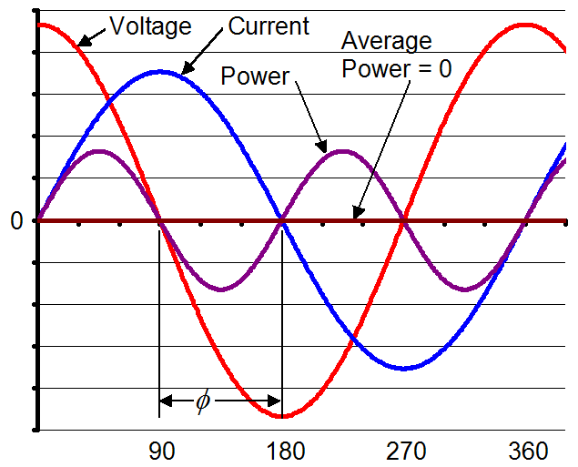
The negative voltage in AC means the voltage is 180 degrees out of phase concerning the positive voltage. A complete cycle of AC consists of two half-cycle one is positive (+) half, and the other is the negative (-) half. The positive half is where the voltage is positive at any instant. Still, during the negative half of the circle, the polarity of voltage gets inverted with respect to the positive half of the cycle, which means at any instant of time during the negative half cycle, the voltage is negative.

Can Thevenin Voltage be Negative?

Thevenin voltage can be defined according to the Thevenin theorem, which states that any linear circuitry is a combination of several voltage sources, and resistors can be replaced by a resistor and a voltage source; the resulting voltage source is the Thevenin voltage.

The polarity of Thevenin voltage can be negative and positive depending upon the orientation of the Thevenin voltage in the circuitry. If the calculated Thevenin voltage is negative, that means the direction of the resultant power source will change. If the calculated value remains positive, then the orientation of the resulting power supply orientation is correct.

Can RMS Voltage be Negative ?

RMS stands for route mean square value. RMS voltage can be obtained by taking the square root of the mean value of squared instantaneous voltage over a time interval

The outcome of a square root can be negative or positive. Suppose the amplitude of the voltage is taken for the RMS, then by convention. In this case, the RMS of the voltage will only be positive if amplitude and phase of the voltage are taken for obtaining RMS voltage, then it can be a complex negative or positive value.

Can Node Voltage be Negative ?

In a circuit, the node is a point between two or more circuit elements, and node voltage is the electric potential difference between two nodes of the circuit.

Node voltage can be positive or negative as it is a relative quantity. One node of the circuit can be considered as a reference node, and with respect to that node, another node voltage can be measured. Generally, the reference voltage is the ground node, so the other node’s value depends on the direction of the current orientation, etc., with respect to the reference node. The measuring node voltage may be inferior than that of the reference voltage.

Can Stopping Voltage be Negative ?

In the Photoelectric effect experiment, the anode is the target material. The anode is connected to the positive terminal of the voltage source while exposed to the monochromatic and electromagnetic wave, which results in current flow through the circuit current is called photocurrent.

When the anode is linked to the negative terminal of the voltage source, as the voltage increases, the photocurrent dies out. The voltage at which the photocurrent stops flowing through the circuit is known as the stopping voltage. Through this experiment, we got to know that the stopping voltage is a negative value.

Can Peak to Peak Voltage be Negative ?

Peak to peak voltage is the difference between minimum voltage and a maximum voltage of a voltage signal.

The magnitude of the peak to peak voltage can vary from 0 to any positive value as the polarity of peak to peak voltage can be negative and positive.

Can Instantaneous Voltage be Negative ?

Instantaneous voltage is the value of the voltage ( or potential difference) at a particular moment of time.

Instantaneous voltage can be negative or positive. The instantaneous voltage of a negative DC voltage source is consistently negative at any instant of time. In AC voltage, the instantaneous voltage varies from positive to negative with time. For the negative cycle of the AC voltage signal, the instantaneous value of the voltage is negative at any instant in time.

Is Current Negative if Voltage is Negative?

Voltage is a relative quantity so that it can be negative. Negative current can only mean the direction of electron current, which is opposite to the electrical current as of the convention.

Negative voltage means the supply’s negative terminal is directly connected to the circuitry, and the positive terminal is grounded. The current from the negative(-) terminal of the voltage source is taken into consideration . That current will be the negative current as we know the electrical current from the positive terminal of any voltage supply.

What does Negative 5 Volts mean?

5 volt is a potential difference (or voltage) between two different points. Acknowledge that voltage is a relative quantity, the polarity of the voltage can change considering the references.

image 6
Image: 5 DC volt supply connected the ground through positive terminal.

When the positive terminal of the 5 DC volt supply is directly linked to the ground. As a result, the positive (+) terminal becomes the reference voltage, and the negative (-) terminal of the 5 volt supply is linked to the circuitry. The resultant voltage through the 5 volt supply will be negative 5 volts as the positive terminal is taken as the reference point.

How do you create a Negative Voltage?

Different methods can be used to generate a negative voltage.

Using :-

With the combination of 555 timers and a clipper circuit, the negative voltage can be generated as output. Here 555 timer act as an astable vibrator. After receiving power from the power supply, 555 will generate a square wave as an output, which will consist of both positive and negative voltage. During the positive half of the output voltage, the capacitor connected with the output gets charged, so there will be no positive voltage. During the negative voltage at the capacitor gets discharged through the diode providing negative voltage as output.

There are several ICS that uses switched capacitor voltage converter to convert a voltage into a negative voltage. Generally, these IC contains non-critical capacitors for the charge pump and charge reservoir. And as the fundamental component of these ICs is oscillator voltage level translator and MOS switches.

As we know half-wave rectifier can filter out positive or negative half of any AC signal as required output is the negative voltage negative half-wave rectifier can be used in this rectifier only negative half of the AC signal can pass through it so as a result, there will only be the negative voltage as output

The voltage gain of inverting amplifier is negative, which means the output of the inverting amplifier is 180 degrees out of phase with the input of the amplifier, so if a positive voltage is fed into the inverting, amplifier, then the negative voltage will be as output.

How do you convert Negative Voltage to Positive?

Negative voltage can be converted into positive voltage as a requirement.

Inverting amplifier can be used to transform the negative (-) voltage into positive(+) voltage. The voltage gain of the inverting amplifier is negative, which means the output voltage is 180 degrees out of phase concerning the input. If the input is taken as a negative voltage, then the output voltage of the inverting amplifier will be positive.

What are Negative Voltage Regulators?

Voltage regulators are used to maintaining a specific range of voltage for different purposes.

A negative voltage regulator is a circuit that is used to maintain the voltage of any specific negative voltage range. 79XX is an IC family which is a three-pin negative voltage regulator.

These ICs are available in 3 different output voltages -5, -12, and – 15. These integrated circuits have intercurrent limiting properties and thermal shutdown protection for their safety.

Can Arduino Output Negative Voltage?

There are several Arduino boards available commercially.

Generally, the output voltage directly from Arduino is in the positive voltage range. The voltage range will vary from one type to another or the pin from which output is taken. For getting negative voltage output from Arduino, external voltage converter circuitry is required for the voltage conversion from positive to negative.

Is Ground Positive or Negative?

The ground is the reference point of the circuitry with respect to which the voltage of any point can be measured.

The ground can be positive as well as negative depending upon the design of the circuitry. In electronics, a positive or a negative terminal of any power supply can be considered the ground. When the supply’s negative terminal is directly connected to the ground, then the ground is called negative ground. When the supply’s positive terminal is directly connected to the ground, then the ground is called positive ground.

Can you Connect Ground to Negative?

The voltage source has two terminals; one is considered positive, and the other is negative.

The ground is the Zero Volt reference point of the circuit. If there is only one supply in the circuit, then the supply’s negative terminal is considered the same as the ground. If required, the ground can also be linked directly to the negative (-) terminal of the DC supply. When the DC terminal is directly connected to the ground, then the ground is called negative ground. There is no positive or negative end in AC supply as polarity changes with time, so a neutral wire from the AC circuit can be directly connected to the ground. The ground is not necessary for every circuit. It is generally used for protection, a common reference point for voltages, etc.

How do you test a Negative Voltage Regulator?

The output and input voltage of the regulator can check for testing the negative voltage regulator.

The input voltage to the negative regulator can be measured with respect to the ground; the regulator’s input voltage is tested so that the regulator can work appropriately with sufficient input voltage. The input voltage must be greater than that of the regulated output voltage in magnitude. The output voltage range differ with distinct voltage regulators. As for the negative voltage regulator, the output voltage range will be in negative voltage values. When a negative voltage regulator is tested, ensure the output voltage is in the negative voltage range. The voltage output must be nearby its rated output voltage. If the output voltage is not around the rated output, then the regulator may be defective.

Which IC is used to get Negative Voltage?

Switched capacitor voltage converter that inverts, divides, doubles, or multiples, the positive input voltage.

IC’s used to get the negative voltage as output are TL7660, MAX1044, NCP1729, LT1026, MAX870, MAX829, LT1054, CAT7660, etc. These IC’s are used in line drivers, operational amplifiers, suppliers, negative voltage generators, voltage splitters, voltage developers, etc. These ICs work for a different range of voltage that’s depends on the specifications of the IC.

Why does Current Flow from Negative to Positive?

The potential difference between the two points in the circuit is the flow of current.

The electron current begins from the negative (-) terminal. It travels to the supply’s positive terminal, as the electron current is in the contradictory direction of the electric convention of current. The flow of electrons is caused by the difference in polarity or the potential difference created by the excess of the electron at one end and the deficiency of electron at other—negatively charged electrons drawn towards the positive end of the supply from the negative end the supply.

What is difference between Positive and Negative Voltage?

Any voltage can be either positive, negative, or zero.

The difference between positive (+) and negative (-) voltage is in the polarity of the voltage. The polarity of the voltage can change with the reference as if a higher potential point is taken as a reference to measure the lower potential. The potential difference will be negative, which is the negative voltage. And when a lower potential point is taken as a reference to measure the higher potential, the potential difference will be positive. The polarity of voltage also influenced the orientation of the DC source. For AC source with time, the polarity of the voltage changes as for the positive half of the AC signal, the voltage is positive, and for the negative half, the voltage is negative.

Wind Turbine Efficiency: 11 Complete Quick Facts

Windmills D1 D4 Thornton Bank 194x300 1

Wind turbine energy production is a growing field of electricity generation; in 2020, the total wind power capacity in the world is 743GW. As the wind plants are producing less pollution, the demand for wind power generation is growing.

The efficiency of a wind turbine depends on many factors, like the type of turbine, the blade geometry, available wind velocity etc. 59% is the maximum efficiency that can be achieved by a wind turbine. The practical efficiency of a wind turbine varies between 30 -45%, and it may rise to 50% during peak wind.

If the turbine is working at 100% efficiency, the wind speed after striking the turbine becomes zero, which is impossible.  

wind turbine efficiency
Windt turbine Credit : https://commons.wikimedia.org/wiki/File:Windmills_D1-D4_(Thornton_Bank).jpg
Wind turbine
Wind turbine Credit:https://commons.wikimedia.org/wiki/File:Wind_turbine.gif

Wind turbine efficiency formula

The calculation of efficiency is essential; the efficiency helps to compare the performance of different wind turbines and optimum wind speed for maximum efficiency.

Co-efficient of power is the more common word for efficiency of the wind turbine. The Cp is defined as,

gif

The amount of electricity produced by a wind turbine can be calculated from the generator output. The below equation calculates the input kinetic energy,

Where,

gif

A is the covered area of the wind turbine, V is the wind speed, ρ is the air density.

The Cp value varies with respect to the wind speed; hence the efficiency of the wind turbine varies while operating.

Further, the Cp depends on turbine parts, i.e. the turbine blades, shafts and generator. Therefore, the multiplication of aerodynamic efficiency of blades, mechanical efficiency of the shaft and electrical efficiency of generator provide the value of Cp.

Maximum efficiency of wind turbine

The maximum possible efficiency of the wind turbine is proposed by Albert Betz, a German physicist, in 1919. It provides insight into the maximum possible turbine efficiency.

The Betz’s limit shows that 59.3% is the maximum possible efficiency of a wind turbine. Hence, the turbine efficiency never exceeds 59%, including all other losses it comes to 35-45% value in practical cases.  

Let’s assume that the efficiency of a wind turbine is 100% that means the turbine consumes all the air energy. If it happens, the velocity of air after passing the turbine becomes zero. That means the air is not flowing, which hinders the further flow of air. Thus, this is an impossible situation.

Now, if the inlet and exit air velocity are the same, that means no energy is extracted, which gives 0% efficiency to the turbine. Hence the maximum possible turbine efficiency is somewhere between 0 and 100%, excluding these limits.

Betz proved that the maximum possible efficiency is 59.3% for a wind turbine with maths and solid physics.

Types of wind turbines and their efficiencies

A variety of wind turbines are available according to the axis of rotation and design of blades. The most commonly used wind turbine is the Horizontal axis wind turbine. However, other kinds of turbines are also used for appropriate conditions. The different types of turbines are,

Let’s discuss the efficiency of these turbines separately,

Horizontal axis wind turbine (HAWT) efficiency

The horizontal axis wind turbines are commonly used for large plants, where enough space and wind is available. The axis of rotation of the turbine blade is parallel to the earth surface.

The efficiency of HAWT varies between 35-50%. Currently, HAWT has the highest efficiency.

The captured wind energy by wind turbine depends on the area covered by the turbine blades. For a HAWT, the area is calculated as follows,

A = πL2

Where, L is the length of blade. The length varies between 20 to 80 meters.

Usually these wind turbines are used for large production plants. Most common horizontal wind turbine is 3 bladed, and the colour of turbines usually white for visibility by aircraft.

Horizontal
HAWT Credit: https://commons.wikimedia.org/wiki/File:Micon-Turbine.JPG

Vertical axis wind turbine (VAWT) efficiency

The vertical axis wind turbines are commonly used for small energy production where the space is constrained. The axis of rotation of blades of vertical axis wind turbines is perpendicular to the Earth surface.

The efficiency of VAWT is less compared to HAWT. 

As discussed, the efficiency depends on the area of turbine blades exposed to wind. For VAWT, the area exposed is,

A = DH

Where D and H are the diameter and height of the blades.

Different kinds of VAWT are available. Darrius wind turbine and Savonius wind turbine are common VAWT. The efficiencies of these two are discussed below.

Vertical Axis Wind Turbine offshore
Vertical axis wind turbine. Credit: https://upload.wikimedia.org/wikipedia/commons/1/1f/Vertical_Axis_Wind_Turbine_offshore.gif

Darrius wind turbine efficiency

Darrius wind turbine is a VAWT.

The efficiency of the Darrius wind turbine is between 30-40%. The usage of these turbines are limited even though these are having high efficiency mainly due to inability to self-start.

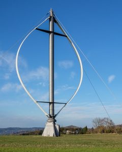
Darrius turbine is a lift based turbine. The figure shows a Darrius wind turbine. As shown below, a number of aerofoil blades are mounted on a vertical shaft that rotates. The blades are stressed only in tension for these turbines due to the curvature. The design is developed by  French engineer Georges Jean Marie Darrieus. These are commonly used near to human habitat, on the top of a building or in the centre of a road. However, the protection of the turbine is tough in extreme conditions.

Darrieus Rotor Ennabeuren 3256
Darrius wind turbine Credit:https://commons.wikimedia.org/wiki/File:Darrieus-Rotor_Ennabeuren-3256.jpg

Savonius wind turbine efficiency

Savonius wind turbine is a different type of VAWT. Unfortunately, the efficiency of these turbines is very low.

The efficiency of the Savonius wind turbine varies between 10-17%. Even though the efficiency is very low, due to the simple structure and reliability of the turbine, these are used to produce a small amount of electricity in appropriate locations.  

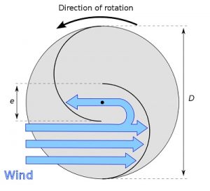
Savonius turbine is drag based turbine. The figure shows an actual Savonius wind turbine. The top view of the blade is also shown in the below figure.

399px Savonius wind turbine
Savonius wind turbine Credit: https://commons.wikimedia.org/wiki/File:Savonius_wind_turbine.jpg
660px Savonius rotor en
Top view of Savonius wind turbine. Credit: https://commons.wikimedia.org/wiki/File:Savonius-rotor_en.svg

Finnish engineer Sigurd Johannes Savonius developed the Savonius wind in 1922. There are two types of blade design for Savonius wind turbine, barrel design and ice wind design. The top view barrel wind turbine is shown above. The blades are half-cylindrical; the barrels are not meeting in the centre; they are away from the centre, which enables the free motion of wind in the blade.

Bladeless wind turbine efficiency

The bladeless wind turbines are a particular type of wind turbine, these turbines don’t have revolving blades, and the turbine works based on vortex-induced vibration.

The efficiency of a bladeless wind turbine is very less compared to any other wind turbine. However, lightweight, cost-effectiveness and less maintenance are the advantages of the bladeless wind turbine. In addition, the turbine requires less space; hence, more turbines can be installed than the usual wind turbine.

Archimedes wind turbine efficiency

Archimedes wind turbine is a recently developed technology. These are small structures and can be used on rooftops, on roads, etc.

Compared to conventional wind turbines Archimedes wind turbines are more efficient. In addition, the turbine reduces many other problems related to conventional turbines. 

For example, the noise produced by Archimedes wind turbines is significantly less compared to the conventional turbine. The shape of the turbine is modelled similar to the spiral of a Nautilus shell. This shape enables the turbine to self-adjust the turbine face according to the wind flow. 

Factors affecting wind turbine efficiency

The efficiency of wind turbines are already discussed above, from that the factors affecting turbine efficiency are,

  • The wind speed.
  • The air density.
  • Blade radius.
  • Type of wind turbine

Wind turbine efficiency comparison

Let’s conclude the wind turbine efficiency here. The wind turbine efficiency is tabulated below.

Turbine Efficiency
Horizontal axis wind turbine 30-45
Vertical axis wind turbine 10-40
Darrius wind turbine 30-40
Savonius wind turbine 10-17
bladeless wind turbines Very less

For more posts on Mechanical Engineering, please follow our Mechanical page

Steam Turbine Efficiency: 15 Important Facts You Should Know

29952475153 c87b98e738 w 300x200 1

Steam turbines convert kinetic energy/pressure energy to mechanical energy; these are used for electricity production by coupling the turbine with a generator.

The practical steam turbine efficiency varies with the turbine’s size, type, and frictional losses. Although the maximum value reaches 50% for a 1200MW turbine, small turbines have less efficiency. The efficiency of the steam turbine is maximised by expanding the steam in different stages instead of a single stage.

Impulse and reaction turbines are two types of steam turbine; the efficiency of these turbines varies. The upcoming section explains the equation of efficiencies.

Steam turbine efficiency formula

Many parameters control steam turbine efficiency. The steam turbine is equipped with a nozzle/stator and rotor. Hence, the efficiency of each component affects turbine efficiency.

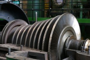
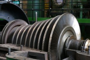
steam turbine efficiency
Steam turbine Credit: https://www.flickr.com/photos/elsie/29952475153

The basic formula for the calculation of turbine efficiency is

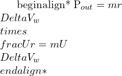
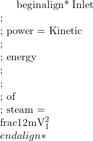
Efficiency = Work done on turbine/input kinetic energy of steam

First, let’s define some of the efficiencies.

Blade efficiency

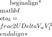
The blade efficiency is defined as, The ratio of work done on the blades divided by the input kinetic energy.

Nozzle efficiency

Each stage of the impulse turbine is equipped with a nozzle and blades.  Hence, overall efficiency is affected by the nozzle efficiency,

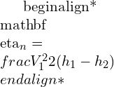
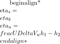
The nozzle efficiency is defined as; the ratio of output kinetic energy from the nozzle to the difference in the inlet and exit enthalpies of the steam.

Stage efficiency

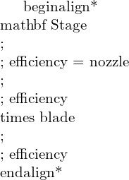
The overall efficiency of the combination of nozzle and blade stage is known as stage efficiency.

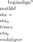
The stage efficiency is obtained by multiplying the blade efficiency with nozzle efficiency.

Isentropic efficiency

The isentropic efficiency is thermodynamic efficiency. This is also known as the 2nd law efficiency of the turbine.

The isentropic efficiency is the ratio of actual work produced in the turbine to the maximum possible work produced if the ideal isentropic process has occurred.

Efficiency of impulse turbine

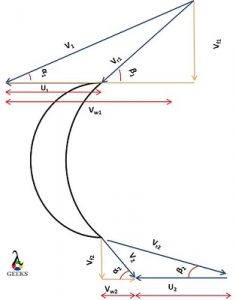
The impulse turbine utilises the kinetic energy of the steam and converts it to mechanical energy. The steam pressure energy is converted to kinetic energy with the help of a nozzle before entering the rotor blades in impulse turbine.

The final efficiency of one stage, i.e. one nozzle and blade set of impulse steam turbine, is given as,

(1)    \\begin{align*} \\mathbf{ Stage\\;\\; efficiency = nozzle\\;\\; efficiency \\times blade\\;\\; efficiency} \\end{align*}

(2)   \\begin{align*} \\mathbf{ \\eta = \\eta_n \\times \\eta_b}  \\end{align*}

Where blade efficiency is,

(3)   \\begin{align*} \\mathbf{\\eta_b = \\frac{2U\\Delta V_w}{V_1^2} }\\end{align*}

Where, U is the blade speed, V1 is the velocity of inlet steam from nozzle and ΔVw  is the difference between whirl component of inlet and exit velocity

And Nozzle efficiency is,

(4)   \\begin{align*} \\mathbf{ \\eta_n = \\frac{V_1^2}{2(h_1-h_2)}} \\end{align*}

Where, h1 and h2 is inlet and exit enthalpy of the steam respectively.

Let’s do the detailed analysis of stage efficiency,

The velocity triangle of impulse turbine is given below.

blades
Velocity triangle of impulse turbine

In the figure, the steam enters from the top and leaves through the bottom.

Vr is the relative velocity of steam

V is the absolute velocity of steam

Vw is the whirl component of steam velocity and Vf is the flow component of steam velocity.

U is the blade velocity

Α is the guide vane angle and β is the blade angle

The suffix 1 and 2 represents inlet and exit, respectively.

The whirl component is helping to rotate the blade and the flow component helps the flow of steam over the turbine. Hence, a momentum is created in the direction of blade rotation due to the difference in whirl component. Applying the law of moment of momentum gives

(5)    \\begin{align*}  Torque = m(r_1V_{w1}-r_2(-V_{w2})) \\end{align*}

The r1=r2=r for an impulse turbine.

Hence,

(6)    \\begin{align*}  T = mr\\Delta V_w \\end{align*}

Now,

(7)    \\begin{align*}  Power = T \\times \\omega \\end{align*}

(8)    \\begin{align*}  P_{out} = mr \\Delta V_w \\times \\frac{U}{r} = mU \\Delta V_w \\end{align*}

(9)    \\begin{align*}  Inlet \\; \\; power = Kinetic \\; \\; energy \\; \\; \\; of \\; steam =\\frac{1}{2}mV_1^2 \\end{align*}

Hence the final blade efficiency is

(10)    \\begin{align*}  \\eta_b =\\frac{mU\\Delta V_{w}}{\\frac{1}{2}mV_1^2} \\end{align*}

(11)    \\begin{align*}  \\eta_b =\\frac{2U\\Delta V_{w}}{V_1^2} \\end{align*}

Substituting blade efficiency and nozzle efficiency in stage efficiency equation,

(12)    \\begin{align*}  \\eta_s=\\eta_b \\eta_n = \\frac{U \\Delta V_w}{h_1-h_2} \\end{align*}

Now let’s find out the ΔVw,

(13)    \\begin{align*}  \\Delta V_w = V_{w1}-(-V_{w2} ) \\end{align*}

(14)    \\begin{align*}  \\Delta V_w = V_{w1}+V_{w2} \\end{align*}

From velocity triangle,

(15)    \\begin{align*}  V_{w1}=V_{r1} cos \\beta_1+U\\end{align*}

(16)    \\begin{align*}  V_{w2}=V_{r2} cos \\beta_2-U \\end{align*}

Substituting these give,

(17)    \\begin{align*}  \\Delta V_{w}=V_{r1} cos \\beta_1\\left ( 1+\\frac{V_{r2} cos \\beta_2}{V_{r1} cos \\beta_1} \\right ) \\end{align*}

(18)    \\begin{align*}  \\Delta V_{w}=V_{r1} cos \\beta_1\\left ( 1+ck \\right ) \\end{align*}

Where,

(19)    \\begin{align*}  k= \\frac {V_{r1}}{V_{r2}} \\;\\;\\;\\; and \\;\\;\\;\\; c = \\frac{cos \\beta_2}{cos \\beta_1} \\end{align*}

Applying ΔVw on blade efficiency equation,

(20)    \\begin{align*}  \\eta_b=\\frac{2UV_{r1} cos \\beta_1\\left ( 1+ck \\right )}{V_1^2} \\end{align*}

From velocity triangle,

(21)    \\begin{align*}  \\eta_b=\\frac{2U(V_1 cos\\alpha_1-U)\\left ( 1+ck \\right )}{V_1^2} \\end{align*}

(22)    \\begin{align*}  \\eta_b=2\\frac{U}{V_1}\\left( cos\\alpha_1-\\frac{U}{V_1}\\right) ( 1+ck ) \\end{align*}

k is the ratio of relative velocities, for  perfect smooth blades, k = 1 and otherwise, k is less than 1.

Differentiating the efficiency equation with respect to U/V1 and equating to zero gives the criteria for maximum turbine efficiency. U/V1 is known as blade speed ratio.

Efficiency of Reaction turbine

Let’s analyse the efficiency of reaction turbine by analysing the most commonly used Parson’s reaction turbine.The degree of reaction of parson turbine is 50%. The rotor and stator are symmetrical and velocity triangles are similar.

The final blade efficiency equation of Parson’s Turbine is given below,

(23)    \\begin{align*} \\mathbf{ \\eta_b=\\frac{2U(2V_1cos \\alpha_1-U)}{V_1^2-U^2+2V_1Ucos \\alpha_1}} \\end{align*}

The reaction turbine uses the reaction force to generate the power. The steam flow over the stator, the stator itself acts as convergent nozzle. The flow to rotor is controlled by fixed vanes known as stator. In impulse turbine the pressure remains constant while the steam flows over the rotor, however, in the reaction turbine the pressure drops while steam flows over the rotor.

Let’s derive the efficiency equation.

Figure shows the velocity triangle of Parson’s reaction turbine.

Parson
Velocity triangle of Parson’s turbine

In the reaction turbine, the primary objective is to find out the total energy supplied by the steam.

In the case of reaction turbine, the energy is supplied in the form of pressure energy also, additional to the kinetic energy. Therefore, the equation of input energy includes the term for kinetic energy and pressure energy. The pressure energy term can be represented with the change in total relative velocity.

Finally, the total input energy

(24)    \\begin{align*} input \\;\\; energy =\\frac{V_1^2}{2}+\\frac{V_{r2}^2-V_{r1}^2}{2} \\end{align*}

For parson’s turbine, V1 = Vr2, V2 = Vr1, α12 and α21

Applying these conditions,

(25)    \\begin{align*} input \\;\\; energy =\\frac{V_1^2}{2}+\\frac{V_{1}^2-V_{r1}^2}{2} \\end{align*}

(26)    \\begin{align*} input \\;\\; energy = {V_1^2}-\\frac{V_{r1}^2}{2} \\end{align*}

From input velocity triangle, applying Cosine rule,

(27)    \\begin{align*} V_{r1}^2=V_1^2+U^2-2V_1Ucos \\alpha_1 \\end{align*}

Hence, the input energy equation becomes,

(28)    \\begin{align*} input \\;\\; energy = {V_1^2}-\\frac{V_1^2+U^2-2V_1Ucos \\alpha_1}{2} \\end{align*}

(29)    \\begin{align*} input \\;\\; energy = \\frac{V_1^2-U^2+2V_1Ucos \\alpha_1}{2} \\end{align*}

The work done is similar to impulse turbine,

(30)    \\begin{align*} workdone= U \\Delta V_w \\end{align*}

(31)    \\begin{align*} U \\Delta V_w=U(V_{w1}+V_{w2} ) \\end{align*}

(32)    \\begin{align*} U \\Delta V_w=U(V_{1}cos \\alpha_1+V_{2}cos \\alpha_2 ) \\end{align*}

(33)    \\begin{align*} U \\Delta V_w=U(V_{1}cos \\alpha_1+V_{r1}cos \\beta_1 ) \\end{align*}

Where,

(34)    \\begin{align*} V_{r1}cos \\beta_1 = V_1 cos \\alpha_1-U \\end{align*}

Hence,

(35)    \\begin{align*} U \\Delta V_w=U(V_{1}cos \\alpha_1+V_1 cos \\alpha_1-U) \\end{align*}

Finally, ,

(36)    \\begin{align*} U \\Delta V_w=U(2V_{1}cos \\alpha_1-U) \\end{align*}

Hence the equation efficiency,

(37)    \\begin{align*} \\eta_b=\\frac{2U(2V_1cos \\alpha_1-U)}{V_1^2-U^2+2V_1Ucos \\alpha_1} \\end{align*}

Condition for maximum efficiency of steam turbine

It is always better to operate the turbine in maximum efficiency.

By analysing the efficiency equation explained above, the variable that we can change is U/V1 , hence by differentiating the equation with respect to U/V1 and equating it to zero yields the condition for maximum efficiency.

Condition for maximum efficiency of impulse turbine

The equation for maximum efficiency of impulse turbine is,

(38)    \\begin{align*} \\mathbf{ \\eta_b=\\frac{cos^2 \\alpha_1}{2}(1+ck)}\\end{align*}

Now, let’s derive the equation for maximum efficiency.

The blade efficiency equation of impulse turbine is,

(39)    \\begin{align*} \\eta_b=2\\frac{U}{V_1}\\left( cos\\alpha_1-\\frac{U}{V_1}\\right) ( 1+ck )\\end{align*}

Differentiating it with respect to , For simplification let’s take ρ = U/V1

Hence,

(40)    \\begin{align*} \\frac{d \\eta_b}{d \\rho}=2(1+ck)\\left[\\left(cos \\alpha_1-\\frac{U}{V_1} \\right )-\\frac{U}{V_1} \\right ]\\end{align*}

Equation it to zero gives,

(41)    \\begin{align*} 2(1+ck)\\left[\\left(cos \\alpha_1-\\frac{U}{V_1} \\right )-\\frac{U}{V_1} \\right ] = 0\\end{align*}

(42)    \\begin{align*} \\frac{U}{V_1} = \\frac{cos \\alpha_1}{2}\\end{align*}

This is the condition for maximum efficiency.

Applying this condition to efficiency equation yields the maximum blade efficiency.

(43)    \\begin{align*} \\eta_b=2\\frac{cos \\alpha_1}{2}\\left( cos\\alpha_1-\\frac{cos \\alpha_1}{2}\\right) ( 1+ck )\\end{align*}

(44)    \\begin{align*} \\eta_b=\\frac{cos^2 \\alpha_1}{2}( 1+ck )\\end{align*}

If blades are equiangular, β12, hence c = 1, and for smooth blades k=1.

Finally, the maximum efficiency of impulse turbine with equiangular smooth blades is,

(45)    \\begin{align*} \\eta_b={cos^2 \\alpha_1}\\end{align*}

Condition for maximum efficiency of reaction turbine

The equation for maximum efficiency of parson’s reaction turbine is,

(46)    \\begin{align*} \\mathbf{ \\eta_{b,max}=\\frac{2cos^2 \\alpha_1}{1+cos^2 \\alpha_1}}\\end{align*}

Now, let’s derive the equation.

The efficiency equation of Parson’s reaction turbine is,

(47)    \\begin{align*} \\eta_b=\\frac{2U(2V_1cos \\alpha_1-U)}{V_1^2-U^2+2V_1Ucos \\alpha_1}\\end{align*}

 Let’s take ρ =U/V1 

Then,

(48)    \\begin{align*} \\eta_b=\\frac{2 \\rho(2cos \\alpha_1- \\rho)}{1-\\rho^2+2 \\rho cos \\alpha_1}\\end{align*}

Differentiating this with respect to ρ

(49)    \\begin{align*} \\frac{d\\eta_b}{d \\rho}=\\frac{(1-\\rho^2+2 \\rho cos \\alpha_1)(2(2cos \\alpha_1- \\rho)-2 \\rho)-2 \\rho(2cos \\alpha_1 - \\rho)(-2 \\rho+2cos \\alpha_1)}{(1-\\rho^2+2 \\rho cos \\alpha_1)^2}\\end{align*}

Equating the above equation to zero yields,

(50)    \\begin{align*} \\rho = cos \\alpha_1\\end{align*}

Applying this on efficiency equation yields the maximum efficiency,

(51)    \\begin{align*} \\eta_{b,max}=\\frac{2cos^2 \\alpha_1}{1+cos^2 \\alpha_1}\\end{align*}

Steam turbine efficiency curve

The curve between ρ and  is efficiency curve.

The efficiency curve for equiangular smooth impulse turbine for α=20o is shown below,

Impulse

The efficiency curve of parson’s reaction turbine for α=20o is shown below,    


Parsons

Factors affecting steam turbine efficiency

Now, we can easily the take out the factors affecting the steam turbine by looking into the efficiency equation.

The factors affecting steam turbine,

  • The blade angle (α1)
  • Inlet steam velocity (V1)
  • The smoothness of turbine blade (k)
  • Blade angle on the rotor.
  • The blade velocity (U)

Thermal efficiency of steam turbine

The steam power plants are based on Rankine cycle. Hence, the efficiency of the plant is calculated based on the Rankine cycle

The thermal efficiency of steam turbine power plant is defined as,

(52)   \\begin{align*} \\mathbf{\\eta= \\frac{(Turbine\\;\\; work-Pump\\;\\; work)}{(Heat\\;\\; added)}}\\end{align*}

Rankine

The figure shows the ideal Rankine cycle, from the figure the thermal efficiency can be calculated as,

(53)   \\begin{align*}\\eta= \\frac{(h_3-h_4)-(h_2-h_1)}{(h_3-h_2)}\\end{align*}

How to calculate steam turbine efficiency?

The efficiency is the ratio of obtained work to given work.

The efficiency of steam turbine can be calculated by measuring the amount of work produced by the turbine to the amount of energy supplied. The supplied energy depends on the steam input, and output power depends on the turbine.

The equation to calculate the turbine efficiencies are explained in previous sections.

 In a steam power plant, we calculate the efficiency by calculating the ratio amount of electricity produced to the energy equivalent of fuel burned. The steam plant efficiency depends each component, which include steam turbine, boiler, pump, electricity generator etc.

How to improve steam turbine efficiency?

The methods to improve steam turbine efficiency are,

  • Improve the design of turbine blades.
  • Minimise the friction loses.
  • Increase steam velocity, achieved by optimising the temperature and pressure of steam.
  • Minimise the leakage of steam in turbine

Filter Capacitor: 23 Important Facts You Should Know

437339684 f643935543 b

Content:

What is a Filter Capacitor?

The capacitor’s impedance can be defined as a function of frequency as the capacitor is a reactive element, it is suitable for using it as an analog electronics filter.

A filter capacitor is a passive filter that consists of the passive element. Capacitor effects of any signal are frequency-dependent. This capacitor characteristic is used to design filters that can filter out a specific frequency range of signals as required.

Filter Capacitor Image

Capacitors
Image Credit: “Capacitors” by oskay is licensed under CC BY 2.0

Working of Filter Capacitor

The capacitor is a reactive circuit element; its impedance and resistance will vary with the frequency signal passing through it.

The working of the filter-capacitor is based on the fundamental principle of capacitive reactance. The value of capacitive reactance changes with the frequency applied to the capacitor for lower frequency signal capacitor offers a higher resistance, and higher frequency signal capacitor provides low resistance. The capacitor is always trying to maintain the capacitance of the capacitor, so the capacitor will try to resist small current flow in the circuit creates capacitor impedance.

Filter Capacitor Replacement

The filter-capacitor can be replaced by Active Capacitor, Inductor filter circuit, FET circuits, etc.

Filter Capacitor Types

The filter-capacitor can be classified as following as basic types:

  • Low Pass capacitor-filter
  • High pass capacitor-filter
  • Bandpass capacitor-filter
  • Bandstop / Band Reject capacitor-filter

Filter Capacitor Formula

As we got to know, there is a relationship between the capacitor’s capacitive reactance (Xc) with the capacitor’s input signal frequency and capacitance.

Xc=1/ (2πfC)

So, the capacitive reactance (Xc) of the filter capacitor is inversely proportional to the frequency (f) of the signal. 

Filter Capacitor Circuit

filter capacitor
Fig. A basic filter-capacitor circuit.

Filter Capacitor Applications

The filter-capacitor is used in various applications such as:

  • Block the DC or AC component of the signal.
  • Bypass DC or AC part of the signal.
  • High voltage filter applications.
  • To limit the frequency band.
  • To remove unwanted noise from the circuit.
  • To remove interference in circuitry.
  • It is used to remove radio noise.

Filter Capacitor Circuit to Block DC and Pass AC

When a capacitor is connected to a series with the DC source in a completely discharged state, the current will flow until the capacitor is fully charged. At that stage, the capacitor voltage is equal to the applied voltage, and at that point, the capacitor is saturated now no current can flow through it, so the capacitor will behave as an open circuit. As we know, DC usually e is a constant value that is it has 0Hz frequency. As the capacitor offers high resistance towards low frequency, when the capacitor is connected in series with the DC source, it will block all the DC components from the signal and let AC pass through it.

DC filter capacitor calculation

As we know, the DC signal is usually a constant value, I.e. it has 0 Hz frequency.

Now Xc=1/ (2πcf) as f=0

Xc=

So for the DC input, the capacitor provides infinite resistance, so I = V/Xc

 As for the value of Xc= , the value of I=0.

Filter Capacitor in Rectifier

The output of the rectifier is pulsating in nature which makes it suitable for DC supply in the electronic circuit, so the capacitor is connected across the load. The filter-capacitor helps to reduce the pulsating behaviour of the rectifier output.

  In a half rectifier circuit, one ideal diode in the voltage source is an AC source with a sinusoidal signal in the positive half of the signal. The diode is in forward bias, so the diode is forward biased, and the capacitor got charged. In the negative half of the signal, the diode is in reverse bias, so no current flow through the diode, and the charged capacitor will discharge through the load resistor, that’s how the filter capacitor reduces the pulsating nature of the output of the rectifier.

To keep the output voltage from reducing too much during capacitor discharge, select a capacitor with a value so that time constant is much higher than the discharge interval. The filter-capacitor is connected in parallel with the load, so this filter circuit is also known as a shunt capacitor-filter. A capacitor is of the larger value connected across the load impedance.

Filter Capacitor for Bridge Rectifier

A bridge rectifier converts AC to DC by using four diodes same as the half-bridge rectifier. The output is pulsating in nature, so a capacitor is connected across the load to make a more pure DC form. The working is the same as the half rectifier filter circuit. The main advantage of a full-wave bridge rectifier is that its output is less pulsating behaviour than that of the half-wave rectifier, so the capacitor size in bridge filter circuit can be smaller than that of the half-wave filter-capacitor.

Filter Capacitor Value Calculation

How to calculate the filter capacitor value in power supply ?

The relation between the capacitance of Capacitor (C) with change (Q) and voltage (V) across the capacitor is defined as C=QV

The relation between the charge and the current is Q= IT

As we know that time is inversely proportional to the time T=1/f

For the above equations, we get C=I/(FV)

Low Pass Filter Capacitor

Low pass filter only passes the frequency signal, which is lower than that of the filter’s cutoff frequency. For this low pass filter, the relationship between capacitor resistance and the cutoff frequency is

fc = 1/(2πRC)

The resistor in the circuit is independent of the variation of the applied frequency, but the capacitor is sensitive to the changes in the input signal frequency.

Picture2
Fig. Diagram of first order low pass filter-capacitor circuit.

When the input signal frequency is low, the capacitor’s impedance is higher than the impedance of the resistor to the input voltage drop across the capacitor. Still, when the input signal frequency is high, then the capacitor’s impedance is lower than that of the resistor does more voltage drop across the resistor. Low frequency gets passed through, and high frequency gets blocked.

 In a low pass filter, the frequencies below the cutoff frequency are known as passband, and the frequency above the cutoff frequency is known as stopband.

Low pass filters are used for

  • To reduce electrical noise
  • To limit the bandwidth of the signal
  • To reduce interference

The gain of the low-pass filter in magnitude can be calculated by

Gain of filter = 20log (Vout/Vin)

Vout-> output voltage of the filter

Vin-> input voltage of the filter

Low Pass Filter Capacitor Type

It can be of two type:

  • First Order Filter-Capacitor
  • Second Order Filter-Capacitor

The low pass filter circuit above has only one reactive component capacitor, called one poll filter or first-order filter.

In the second-order of the low pass filter, it has to the reactive element that is capacitor in its circuit does design is helpful when the signal does not provide a wideband range between desired and undesired frequency components.

Picture3
Fig. Diagram of second order low pass filter.

Bypass Filter Capacitor

Here one end of the capacitor is linked to the power supply, and the other is linked directly to the ground. This capacitor helps to reduce the effect of voltage spikes or any AC component from the power supply; it shorts the AC signal to the ground and reduces AC noise to produce a much clear DC signal.

Picture4
Fig. Diagram of Bypass filter Capacitor.

The capacitor in this circuit must have at least one-tenth of resistance as that of the resister Re. As we know, electric current chooses the path with a low resistance to following if it has multiple paths to choose from is; the capacitor offers great resistance to low frequency, so only the AC component of the signal passes through it. The DC component of the input signal will pass through the resistor Re.

High Frequency Filter Capacitor

A high pass filter is a filter that blocks low frequency and let pass through the higher frequency signal here. The frequency lower than the cutoff frequency is blocked, and the frequency higher than the cutoff frequency allowed to pass through this filter is also called a low cut filter. A capacitor is linked in series with the input supply; the resistor is linked in parallel.

Picture5
Fig. First order high pass capacitor-filter circuit.

 As we know, when the frequency of the input signal is low, the capacitor’s impedance is higher as the capacitor is in series with the power supply through which only a high-frequency signal can pass it.

The above circuit is a first-order high pass capacitor filter as there is only one reactive element in that circuit.

The second-order high pass capacitor-filter and the first order high pass capacitor filter are cascaded together to form a second-order high pass capacitor-filter.

Picture6
Fig. Diagram of Second order high pass capacitor-filter.

3 Terminal Filter Capacitor

Three terminal capacitor-filters consist of a three-terminal capacitor, which features a more negligible impedance than two terminal capacitors. Which allows it to reduce the impedance in the higher frequency band with lesser number of the reactive element it has great noise suppression effect these are used in power lines of circuit, smartphones, LED TV etc.

Harmonic Filter Capacitor

The harmonic filter can be designed of series or parallel reactive elements to block or shunt the harmonic currents. They can be available in several shapes and sizes. Still, when this capacitor is connected in parallel with the power supply, it helps reduce harmonic current and voltage in the circuitry.

The capacitor required in the harmonic filter must accept the given magnitude of various orders of harmonic current. A harmonic current can be a non-sine wave since the capacitor is very sensitive towards the high tension value. The capacitor is used in the harmonic filter in specific ranges depending upon the capacitor in use. A harmonic filter is formed by a capacitor bank, mainly a group of capacitors of the same rating. This filter converts the harmonic current into heat to protect the load from it.

Feedthrough Filter Capacitor

The feedthrough filter-capacitor is a three-terminal capacitor whose grounding impedance is a small and low effect on the lead impedance. It is specially designed for more efficient performance in filtering circuit.

 The ordinary capacitor is not very good for filter application as they have a high impedance which is undesirable and can affect the efficiency of the filtering circuit feedthrough filter capacitor has a small value of shunt capacitance. This capacitor is used in AC and DC supply lines to reduce harmful interference.

The feedthrough filter-capacitor has a filtering effect close to that of an ideal capacitor. The capacitor was initially designed for DC power lines in the RF system, blocking RF energy and letting DC signals pass through it.

Line Filter Capacitor

The line filter capacitor is a capacitor used to suppress electrical noise generated from the power supply.

 The power supply can have various disturbances that include transient surges and fluctuations in its supply voltage. To reduce the effect of such noise, line filter capacitors use line filter capacitors that can endure fluctuations or transients for a more extended period without falling into it.

Line filter capacitor is used to

  • keep potentially damaging line transients
  • To reduce line disturbance produced by the source
  • To reduce the circuit generated noise

 There are two topologies used in the line filter: one is an X capacitor, and the other is a Y capacitor.

 In X Capacitor, here capacitor is connected across the line supply X capacitor is used where cellular could not lead to an electric shock. It eliminated the electrical noise coming from the power supply and made it used in high-frequency applications. The capacitance of X capacitor can range from 1microF to 10MicroF.

Picture7
Fig. Diagram of X capacitor connected to the power supply.

Y capacitor,  in this topology, capacitors are connected between the line voltage supply and the chassis of the appliances list of colleges used for an application that could lead to electrical shock. The range of this capacitor can be from 0.001 micro F to 1micro F.

Picture8
Fig.  Diagram of Y filter Capacitor.

Filter Capacitor in a Power Supply Circuit

Picture7 1
Fig. Diagram of X capacitor connected to the power supply.

Alternator Filter Capacitor

Alternator stator windings generate the current 3 phase AC. There is not much ripple voltage to produce radio noise. A diode converts the AC to DC, and if any alternator diode fails, the ripple voltage will increase, or noise can be caused by those who have electrical connections. Still, a filter-capacitor can be used to minimize the noise in the circuit. The filter-capacitor can either block the unwanted AC voltage or bypass the unwanted AC voltage back to the source.

Electrolytic Filter Capacitor

An electrolytic capacitor is a capacitor whose positive plate is made of metal and covered by an insulating oxide layer over the metal. This capacitor uses an electrolyte to have a massive capacitance than other capacitors. The capacitor is used in a filter circuit that combines AC power DC voltage electrolytic capacitor filter to eliminate 60 Hz to 120 Hz AC ripple in DC power supply.

EMI Filter Capacitor

Capacitors used in filtering electromagnetic interference in AC and DC power lines are known as EMI filter capacitors. This capacitor can fail due to over-voltage and transients. There are two different types of topology used in filter capacitor X, and Y.  X capacitor topology is used for differential mode EMI filtering. In contrast, Y capacitor topology is used in standard mode EMI filtering.

Theoretically, several capacitor technologies design X or Y capacitors, but the most commercially available are film capacitors or ceramic capacitors.

Filter Capacitor Design

Filter capacitors can be designed in different ways as per requirement.

 When a low pass filter is created, the capacitor is then connected across the load. When a high pass filter is designed, the filter-capacitor is in series with a power supply. The capacitor-filter is used as a bypass filter when the capacitor is connected between the ground and power supply. Different filter capacitors can be designed based on the different ranges of operations, costs, decisions, operating temperatures and sizes.

Filter Capacitor Amplifier

The filter capacitor has a great disadvantage: the amplitude of the output signal is lower than that of the input signal due to an attenuation of the signal. This means the overall gain of the filter-capacitor is less than one, so there may be a need to amplify the output signal.

 Different amplifiers can be used to restore or control the attenuated signal, such as OpAmp, transistors or FETs. After the capacitor-filter amplifier can draw power from an external source to boost or amplifier the output signal through the capacitor-filter, the output signal of the capacitor-filter can be altered or reshaped as required by the amplifier circuit.

Filter Capacitor Selection

How to select filter capacitor value ?

Select the capacitor-filter based on:

  • Cost
  • Precision
  • Range of operation
  • Stability
  • Leakage current
  • Size
  • Operating temperature

High Voltage Filter Capacitor

High Voltage capacitor passive circuit component that can store charge and energy for use in High Voltage application, ordinary capacitor cannot be used in high voltage applications so high voltage capacitor used in higher voltage range application such as high voltage power line filtering, high voltage AC or DC filtering, high voltage AC or DC bypass, etc. These capacitors are designed where the two metal plates of the capacitor are separated by dielectric metal in between for efficient operation in high voltage application.

How to Test Filter Capacitor

There are two ways to check the filter-capacitor:

  1. Before checking the capacitor, make sure the capacitor is fully discharged. If it is not fully discharged, then discharge the capacitor by connecting it through a load. If you are using a multimeter, then set the metre to read high ohm range. Correctly connect the positive and negative end of the capacitor with the multimeter. The meter should begin from 0 and then move towards infinity, that shows the capacitor is in working condition; if the meter stays at 0, then the capacitor is not charging through the meter, that shows it is not working properly.
  2. Another way to test the filter capacitor, charge the capacitor with the DC voltage supply and then observe the voltage across the anode and cathode of the capacitor. In this test, the capacitor’s polarity is essential just before applying the voltage. Check the capacitor after charging, disconnect the voltage source from the capacitor, and use a multimeter to observe the voltage on the capacitor. Upon checking, the charged capacitor must hold the voltage applied. The voltage will rapidly drop to zero when the multimeter is connected because the capacitor will be discharging through the multimeter. If the capacitor is not holding any value near the applied voltage, then the capacitor is not working correctly.

SMD filter capacitor

SMD stands for surface mounted device which means SMD capacitor is the surface-mounted capacitor nowadays SMD capacitor is widely in use as a filter because they are smaller in size and can be placed easily on the circuit board surface mounted technology allows faster and reliable construction of Electronic element, so it is capacitor are readily available and having cheaper and higher performance.

FAQ

What does a filter capacitor do ?

Filter-capacitors can be used for different purposes with different arrangements in the circuit.

The filter-capacitor can be used to restrict the DC component of the input signal. It can also reject or bypass the AC component of the input signal. Filter-capacitors can limit the signal’s bandwidth or remove a specific range of frequency from the signal. It can also be used to remove unwanted components or noise from the circuitry.

How to select filter capacitors?

Select the capacitor-filter based on:

  • Cost
  • Precision
  • Range of operation
  • Stability
  • Leakage current
  • Size
  • Operating temperature

What is the effect of a capacitor as a filter?

The capacitor is used as a filter. It can filter out AC or DC components from the signal or eliminate a specific frequency range.

Capacitor offers high resistance towards the low-frequency input signal. In contrast, it offers low resistance to the high-frequency signal, so when the capacitor is connected in series with the power signal, only the AC component can pass through that. Only the DC component can passes through the load when the capacitor is linked in parallel to the load.

What are the advantages and disadvantages of capacitor filter?

There are several advantages and disadvantages of capacitor filters.

The advantages of capacitor-filters are cheaper, smaller in size, readily available. The disadvantages of the filter-capacitor are that it is sensitive to temperature change, its capacitance reduces with time.

What happens when filter capacitor value is larger?

The larger the filter-capacitor value, the size of the capacitor also increases with it.

With a larger filter capacitor, the voltage will be minimal. The time constant will be large. The charge will be maintained for a longer period, but it will draw a large amount of current and take a long time to complete the charge and be expensive.

Which one is best either capacitor filter or inductor filter?

The filter can be designed with either a Capacitor or Inductor or by using both.

Capacitor-filters are cheaper than inductor fitters. The size of the filter-capacitor is always less than the size of the inductor filter. The capacitor-filter is better at a smoothening voltage, whereas the inductor filter is better at smoothing current.

Which type of capacitor is used in a low-pass filter?

In a low pass filter, the capacitor is connected across the load.

The type of capacitor used in low pass filter depends on the operating range, temperature, sensitivity, stability, cost, size, etc. The capacitor, which fulfils the requirements, can be used.

What is the difference between a rail and a filter capacitor in a circuit?

A rail capacitor is used in power rail, and the filter capacitor is used for different purposes.

A rail capacitor is used to filter out the noise or ripple in the rail power line. This capacitor is mainly used to maintain the voltage in its rated value and to stabilize it. Where is the filter capacitor used for different purposes such as to eliminate the AC component of the signal, block DC component signal, as bypass filter, EMI filter, limit the bandwidth of the signal, eliminate a specific range of the signal, etc.

Why do we use capacitors as filters in rectification when capacitors are used to block DC and allow AC?

When we use a filter-capacitor in the rectification circuit, it only reduces the AC component of the signal.

In the rectifier circuit, the filter-capacitor is linked in parallel to the load appliances circuit. The DC component of the input signal can pass through the load, and the AC component of the input signal will pass through the filter capacitor. The capacitor shows low resistance towards the high-frequency signal.

What is the effect of filter capacitance magnitudes on the ripple voltage in DC power supplies?

When the filter-capacitor is connected in series with the DC power supply, it reduces the power supply’s AC component.

 A filter-capacitor is used in circuitry to minimize the ripple voltage of the power supply.

The ripple voltage output from the filter can be calculated by 

Vr= Vp/(2fCR)

Where Vr =ripple voltage

Vp = peak voltage

f= frequency of the signal (supply)

C= Capacitance of the Capacitator

R= the value of the resistance

Heat Pump Work In Winter: 13 Important Concepts

Heat pump 300x206 1

How does a heat pump work in winter? It is always a curious question for all of us. We know that in winter the objective of heat pump is to heat the room. Let’s analyse the working of heat pump in winter.

During winter, the liquid refrigerant sucks heat from outside air and becomes vapour form; the vapour refrigerant is compressed to high temperature and pressure. Then the refrigerant is allowed to pass through the room. During that period, the refrigerant releases the heat to the room, by which the room temperature increases. 

This system is a good option for places where mild winter occurs, and it can save energy compared to conventional heating. However, for severe winter, the heat pump alone is not a good alternative. The hybrid system is used in that scenario.

There different type of heat pumps are available. The classification is based on from where the heat is taken, i.e. the location of evaporator. Some of the types are :Air source heat pump, Ground source heat pump, water source heat pump etc.

A schematic diagram of heat pump with main components are shown in figure below;

How Does A Heat Pump Work In Winter
The main components of a heat pump
small air source heat pump 4963069 960 720
The outside unit of a small air source heat pump Credit: https://pixabay.com/de/photos/kleine-luft-w%c3%a4rmepumpe-4963069/

How does a ground source heat pump work in winter?

The temperature below few feet from the ground is at a stable temperature of 55oF irrespective of the season. Let’s see how this fact is utilised to run a heat pump.

In ground source heat pumps, series of strong pipes are installed below the ground; this is the ground source heat exchanger. Coldwater from the heat pump is circulated through these pipes, and the water absorbs heat from the ground. Then, the water transfers this heat to the refrigerant in the heat pump. 

A schematic diagram is shown below.

Heat pump
Ground source heat pump Credit :https://www.flickr.com/photos/sagabardon/5086132916

The ground source heat pump eliminates the burning of fossil fuel; hence this is environment friendly. Germany, USA, Sweden, Canada, Switzerland are the main countries using this heat pump.

What temperature is a heat pump not effective?

The heat pump is not advised in all temperatures. The ambient temperature influences the effectiveness of the heat pump.

As the ambient temperature decreases the effectiveness of heat pump decreases, from the research the limiting ambient temperature is calculated as 40oF. Hence, a heat pump is advised to use when the ambient temperature is above 40oF. The heat pump becomes less effective than other heating options when the temperature reduces to 25 to 30oF.

Hence, we use an alternative system in those regions where the temperature falls below 40oF. Fossil fuel or any cheap fuel is burned to extract heat in these regions during peak winter.  

The heat pump is working between two temperature limits, room temperature and ambient temperature. Therefore, the performance of heat pump depends on both these temperature. One can assume that if the ambient temperature is low, the heat pump consumes more work to extract the heat; hence efficiency decreases.

Let’s analyze the effectiveness of heat pumps mathematically. The effectiveness of a heat pump is measured as Coefficient of performance (COP). COP is defined as

COP = (Heating effect)/(Work done to the system)

Let’s analyze the COP of a Carnot cycle. Carnot cycle is an ideal cycle that has the maximum COP.

The COP of the Carnot cycle is defined as;

COP = Thot/Thot – Tcold

Tcold is the ambient temperature, and Thot is the room temperature. Let’s assume that we set 68oF in heat pump, hence the room temperature is 68oF. Now let’s assume two conditions when the ambient temperature is 40oF and 20oF.

When these temperature conditions are applied, we get COP of 11.5 and 6.7 for the ambient temperature of 40oF and 20oF, respectively.

(Note: Care should be taken while calculating the COP, the temperatures should be in Kelvin scale or Rankine scale.)

Here, the COP is reduced when the ambient temperature is reduced. The calculated COP is for the maximum possible cycle. This COP cannot achieve in an actual cycle. Hence, we can conclude that as the ambient temperature decreases the COP of heat pump decreases.

What temperature should I set my heat pump in the winter?

This is always a concern for many of us while operating a heat pump.

The human comfort is the primary objective of a heat pump in home. From scientific researches, it is concluded that 680F is best for human comfort during winter. It is advised to reduce the operating temperature further when we use the heat pump continuously. 

Can heat pump work below freezing?

The question here is what happens when the ambient temperature is below freezing point. Is it safe to operate?

Yes we can use heat pump in freezing conditions. The freezing point of refrigerant used in a heat pump is far below the freezing point of water; hence the refrigerant in the heat pump will not freeze even though ambient temperature is below the freezing point of water.

If the question is “is it advised to use heat pump in extreme cold?” then the answer is “no it is not advised”

However, in extremely cold conditions it is not advised to use heat pump. We discussed the effectiveness of heat pumps in previous sections. When the temperature is less than 40oF, the effectiveness of the heat pump reduces; hence heat pump consumes more energy than simply burning fuel.

How can I make my heat pump more efficient in the winter?

Some tips to improve the efficiency is given below.

  • Clean the filter frequently.
  • For fast heating of the room, do not set the heat pump temperature very high.
  • Don’t heat the spaces which you are not using.
  • Perfectly close all the ventilations in the room.
  • Always provide enough space in indoor and outdoor unit of heat pump for free flow of air.
  • Only put emergency heat mode when it is an emergency.
  • Make sure that the outdoor unit is easily accessible for cleaning.

Why is my heat pump blowing cold air when the heat is on?

There are mainly three reasons that you may feel that your heat pump is blowing cold air.

  • The heat pump is working correctly, but you are feeling it cold.
  •  The heat pump started working on defrost mode.
  • The heat pump is not working correctly.

Let’s discuss each point separately.

  • The heat pump is working correctly, but you are feeling it cold.

The heat pump is working correctly; however, when the ambient temperature is very low, the heat pump’s effectiveness and the ability to increase the temperature reduces. In these situations, the heat pump is heating the air, but you do not feel it as the temperature of heated air is far below your body temperature.

Generally, the electric heating starts automatically in these situations.  

  • The heat pump started working on defrost mode.

When a heat pump is working at a very low ambient temperature, water may freeze around the outdoor unit’s coils. The complete covering of the coil with ice should be avoided. The heat pump works on reverse mode to remove this frost, i.e., it starts cooling inside and heating outside coil.

After 1-2 minutes of operation, the heat pump starts working properly when the frost is completely removed.

  • The heat pump is not working correctly.

This is a serious issue, and you should contact a technician. There are many possibilities like leakage of refrigerant, damages in valves or reduction in heat pump efficiency, etc.

 Should I run my heat pump on auto or heat?

 There are three modes in a heat pump “Heat”, “Cool,” and “Auto”. 

It is advised to set “Heat” mode rather than “Auto” mode in the winter season. This is because the “Auto” mode may cool the room on a sunny winter day, which is unnecessary, i.e., the heat pump automatically gets reversed its operation, which should be avoided.

Should I turn my heat pump off in extreme cold?

The extreme cold situation may occur in winter in many countries.

It is advised to stop using the heat pump in an extreme cold situation as the effectiveness of the heat pump decreases, which leads to increased energy consumption, as discussed above.

Usually, the heat pump comes with an electric heating facility. Hence, in an extreme cold situation, the heat pump gets switched off, and electric heating starts automatically.

How long should a heat pump run per day?

We know that the old furnace heating technique won’t run continuously for a long time. What about the heat pump?

The heat pump can run continuously throughout the day if it is required. The advanced heat pumps come with automatic sensors, which allow the heat pump to stop operating when the required temperature is achieved; it starts automatically when the temperature drops. Hence, you should not worry much about energy consumption.

However, you can reduce energy consumption by manually setting the off time in a heat pump.

How do I know if my heat pump is defrosting?

Defrosting is very common in a cold situation. Defrosting cycle may be required for the efficient working of the heat pump.

You can know that the heat pump is working on defrosting cycle if the following is observed.

  • The indoor fan of the heat pump turns off
  • The heat pump stops heating the room
  • The defrosting indicator light blinks
Ecodan outdoor unit in the snow
Frosting in outdoor unit of heat pump Credit: https://commons.wikimedia.org/wiki/File:Heat_pump_model.jpg

How do I keep my heat pump from freezing up?

The outdoor coils of the heat pump may freeze while operating.

The defrost cycle is to avoid the freezing up of the heat pump. The operation of the heat pump reverses in defrosts cycle, and during that period, the heat pump cools indoors and heat outdoor so that the ice melts. This cycle operates automatically. Within 2-3 minutes, the heat pump starts operating normally. 

How do you unfreeze a heat pump in the winter?

You can unfreeze the heat pump in the following ways,

  • Defrosting cycle. In heat pumps defrosting cycle operates automatically. 
  • Remove the frost manually; you can pump water to the frost until it is melted. Or you can chip the frost with a tool

How much frost is normal on a heat pump?

We cannot say the normal frost quantitatively.

There are two conditions when you can say that the frost is too much in a heat pump.

  • When the frost prohibit the flow of air to the heat pump
  • When the frost is staying on the coils for more than 2 hours.

If these conditions are observed, it is advised to contact an operator as the defrost cycle is not running in your heat pump.

How does a pool heat pump work in winter?

The working of a pool heat pump is similar to the air heat pump.

The pool heat pump is used to heat the water to the swimming pool. In this, the condenser transfers heat to the cold water. The other processes are similar to the room heat pump. Hence, the condenser is dipped inside the swimming pool, and the remaining unit is outside the pool.

For more posts on Mechanical Engineering, please follow our Mechanical page.

Cam And Follower: 9 Interesting Facts To Know

weaving 2747847 960 720 300x200 1

Cam and follower is a mechanism used to get the desired motion such as reciprocating or translational from an available input, usually rotational.

The cam and followers have numerous applications in industries and real life. Its application varies from simple child toys to high precision valve systems in IC engine. Here we are discussing about some of the examples of cam and follower.

We will discuss 10 cam and follower examples


Cam and follower in IC engine

Valves in IC Engine

There are two valves in a four-stroke IC engine. The suction valve and exhaust valve. Those valves have to be opened accurately for the better performance of the IC engine. The suction valve should open during air intake to the cylinder, and the exhaust valve should open to remove the combustion product. The accurate opening of these valves is operated by a cam and follower mechanism.


Generally, a radial plate cam with a flat-faced or spherical follower is used.


Generally, an engine consists of multiple cylinders; hence, each cylinder requires a cam mechanism. All the cams are located on a camshaft. The camshaft is linked with the crankshaft through a chain or belt drive or gear mechanism. Hence, the camshaft is driven by the engine itself.
The number of camshafts varies with the engine. The figure shows two camshafts, one for the exhaust valve and one for the suction valve.

Operation of the fuel pump in Diesel engine   

The fuel pumps are used in the Diesel engine. In a Diesel engine, the only air is added to the cylinder in the suction stroke; after compressing the air to high temperature and pressure, fuel is injected through a fuel pump. The fuel pumps are operated by a cam and follower mechanism similar to the valves.

Separate camshafts are provided for using the fuel pump in the engine.

Cam and follower examples
Cam and follower used in IC engines. The two cam shafts are visible in the figure.
Credit: https://commons.wikimedia.org/wiki/File:Engine_movingparts.jpg#filelinks

Cam and Follower in Industries

Cam automatic lathe

An automatic cam lathe is a machine in which the movements of tools are controlled by the cam and follower mechanism. This machine has high speed, high accuracy, and less noise.

The tool has to move axially and radially; two cams are provided in automatic lathes; a cylindrical cam and a plate cam. The plate cam is used to provide the radial motion of the follower, and the cylindrical cam is used to provide the axial motion of the tool.

Cam indexer

The cam and follower are commonly used in the automatic manufacturing system. The application of cam is automatic indexing of the tool; hence the cam follower system is known as cam indexer. The primary purpose is the positioning of the tool.

The cylindrical cam or globoid cam with a rotating follower is used in cam indexing.

During the cam indexing period, the tool rotates and comes to the required location, then comes the dwelling period. The machining operation is carried out during the dwelling. The cycle is repeated.

The automatic screwdriver, rivets, etc., are some examples where cam indexers are used.

Weaving industry

Cam and follower are used extensively used in a weaving machine to get the shedding motion.

Shedding is the process of separating the warp yarns to make the space for passing the filling yarn. In weaving, one warp yarn is lifted above the other warp yarn, and the filling yarn is passed through the space; after this, the lifted warp yarn is returned, and the other warp yarn is lifted, and the filler yarn is passed through the space. The process is repeated. Hear, we can see the ascend, dwell, descend and dwell of the follower. There are two followers which are connected to the warp yarns. Hence, the conjugate cam and follower mechanism is used for this purpose.

weaving 2747847 960 720
Weaving operation. The white threads are warp and the pink is filler. We can see a space between the white threads through which the filler is passed in each weaving operation. Credit: https://www.piqsels.com/id/public-domain-photo-fedto

Paper cutting

There are mainly two motions in paper cutting. The transverse motion of paper that is to be cut and the motion of the tool. The tool is operated by a cam and follower mechanism. The tool is connected to the follower, and the tool reciprocates. When the tool is not cutting the paper, the paper makes the transverse motion using the Geneve mechanism.

Automatic copying machine

The cam and follower mechanism can be used to copy the surface profile of a component. Usually reciprocating cam is used for this purpose.

We need to copy the cam profile in this scenario. Hence the follower is mounted on the cam with a cutting tool on the other end. During the reciprocatin motion of the cam the follower cut the workpieces which is mounted on the other side of the follower. The workpiece profile will be same as that of the cam in the end of the cutting operation.

Cam and follower in real life

Wall clocks

The cam and follower mechanism are used in wall clocks. 

The heart shaped cam were used in early post office model clocks to synchronise the clock time with Greenwich Mean Time.

Toys

Different variety of toys can be made using cam and follower mechanisms. The mechanism can achieve the repeated motion in toys very easily.

Pin Tumbler Lock

Pin tumbler lock is special kind of lock where cam and follower mechanism is used to prevent the opening of the lock without the proper key.

Pin tumbler lock all
Working of pin tumbker lock. Credit: https://upload.wikimedia.org/wikipedia/commons/1/18/Pin_tumbler_lock-all.JPG

The figure shows the working of pin tumbler lock.

The first two figures shows the operation when the correct key is inserted. When we insert the correct key, the gap between driver pin(blue) and key pin (red) align with the edge of the plug (yellow), which allows the free rotation of the plug hence the lock can be opened.

When wrong key is inserted (left bottom figure), the key pin and driver pin gap will not along with the plug, hence it prevent the opening of the key.

The last figure (bottom right) shows the position of key pin and driver pin when key is not inserted.

FAQ

Why cam and follower are used?

Cam and follower mechanism is extensively used in ic engine, industries and in real life.

It is a simple, compact mechanism that can work with high accuracy, and a large variety of motions can be generated by the proper design of cam profile.

What are the applications of cam and follower?

There is a variety of applications for cam and follower. Some are listed below.

  • The valves of IC engines are operated by cam and follower
  • Conjugate cam is used in the weaving industry for getting shedding motion
  • A large variety of toys uses a cam and follower mechanism.
  • Cam and follower are used in automatic lathe machines.
  • Cam mechanism used for tool indexing
  • Cam and follower are used in paper cutting machines.
  • Cam and followers are used in conveyor belts.

What is the material used for making camshafts?

Chilled cast iron is used for making the cam shafts.

What is the application of cam and follower in the weaving industry?

In the weaving industry cam and followers are used to get the desired motion in the process known as shedding.Shedding is the process of separating the warp yarns to make the space for passing the filling yarn. The conjugate cam follower mechanism is used.

Two concentric cams are connected on a shaft in the conjugate cam and follower mechanism, separate followers attached to each cam. The unit rotates together, and the follower rise or falls accordingly.

What are the application of cam and follower in automobiles?

The main applications of cam and follower in automobiles are given below,

Application of D Flip Flop: 73 Interesting Facts To Know

image 7 1

Shift Register using D flip flop

A flip flop is also a single register that can store one bit when a register is designed with multiple flip flops, which can hold more bit data. Finally, a shift register is a type of logic circuit used to store or transfer data.

The shift register is designed with different numbers of flip flops, where data can be conveyed from left to right or right to left. It can have parallel input or serial input and serial output or parallel output. The shift register can also be designed with D flip flops also.

Serial In Serial Out Shift Register using D flip flop

In this type of register, the input is serial one bit at a time, and output is also serial one bit in a serial sequence.

application of d flip flop
Fig. Serial In Serial Out shift register design with D flip flop

Each flip flop can store one bit at a time, so for a 4-bit shift register, four flip flops are needed. As shown above, serial data is applied through D of the 1st Flip flop to all remaining flip flops. When a series of data feeds to the register, each bit is provided to the next flip flop with every positive edge of the clock pulse, and with every clock pulse, the serial data moves from one flip flop to the next flip flop.

2 Bit Shift Register using D flip flop

The following diagram is the diagram of a 2-bit shift register that can store or transfer 2-bit data. Where input data and output data are both in serial sequence, so it is a Serial in Serial out (SISO) shift register of two-bit, the process of entering data begins with the lowest significant bit of the register, the data input enters the register with every positive edge of the clock pulse.

image 8
Fig. 2 bit shift register using D flip flop

Disadvantages of SISO:

Parallel In Serial Out Shift Register using D flip flop

Here are four different data lines for the 4-bit shift register; each D flip flop has its separate input. Data is fed into the respective registers in a parallel way. With every clock pulse, the data bits are shifted towards the output Z. here, and the output comes out in the serial sequence form. Parallel in Serial Out (PISO) shift register can be of two types of data loading: synchronous loading and asynchronous loading. With this shift register, the data in parallel form can be converted into the serial form of data.

image 9
Fig. Circuit diagram of parallel in serial out shift register.

4 bit Bidirectional Shift Register using D flip flop

A 4-bit bidirectional shift register is a type of shift register in which data bits can be shifted from left to right or right to left as per requirement. When the Right/Left is high, the circuit works as a right shift register, and when it’s low, this circuit acts as a left shift register, and the data shift with every positive edge of the clock pulse in this type of register.

image 10
Fig. Diagram of 4 bit bidirectional shift register designed with D flip flop

4 bit Universal Shift Register using D flip flop

It is a bidirectional shift register, where input can be fed in serial or parallel ways, and output can also be in serial or parallel. That’s why it is called a universal shift register. Moreover, it can be developed with a D flip-flop, as shown in the given figure of the universal shift register.

image 12
Fig. Circuit diagram of universal register using d flip flop.

8 bit Register D flip flop

The 8-bit register can be designed with an 8 D flip flop.

image 13
Fig. Diagram of 8-bit universal shift register designed with D flip flop

D type flip flop Counter

The counter can be designed with a D flip flop; the number of flip flops depends on the number of bit counters to be developed. In addition, both synchronous and asynchronous counters can be created with the d flip flop.

Counter circuit D flip flop

A counter is a group of flip flops whose state changes with every clock pulse applied. The counter is used to count pulses, form waveform, generate a required sequence, etc.

A counter can be a synchronous or asynchronous counter. The ripple counter is an asynchronous type counter. Several states that counter that pass through before returning to the initial state are called the counter’s modulus.

D flip flop up Counter

The counter starts from the minimum digit value of a counter according to the number of flip flops used to design the counter and goes to the maximum capacity of the counter with every clock pulse. So that is an up counter.

D flip flop Down Counter

The counter starts from the maximum value of the digit according to the number of flip flops used in the counter and goes down to the minimum digit value of the counter. So that’s down the counter.

D flip flop Asynchronous Counter

In this type of counter, each Flip Flop has a different clock pulse; the output of this type of counter is independent of a clock pulse; here, the output of a flip flop can be fed into the next flip flop as a clock pulse.

Ripple Counter using D flip flop | Asynchronous D flip flop Counter

Ripple counter, or asynchronous counter, is the simplest form of counter, which is very simple to design and requires very little hardware. However, Flip Flop does not operate simultaneously; each Flip Flop works at different time instances, and each Flip Flop toggles with a clock pulse. Therefore, to design a ripple counter from a d flip flop, the d flip flop must be in a toggle state so that with every clock pulse, it toggles.

4 bit Binary Ripple Counter using D flip flop

image 14
Fig. 4 bit ripple counter designed with D flip flops

3 bit D flip flop Counter Asynchronous Up Counter using d flip flop


image 15
Fig. 3 bit ripple counter which can counter using D flip flop.

2 bit Binary Counter using D flip flop

image 16
Fig. Diagram of 2 bit binary counter designed with D flip flop

3 bit Asynchronous Down Counter using D flip flop

image 17
Fig. Diagram of 3 bit asynchronous down counter designed using D flip flop

Decade Counter using D flip flop

A decade counter is a counter which can count up to 9, the counter starts from 0, and with every clock pulse, it counts up to nine, and when it reaches nine, it resets itself to 0.

image 18
Fig. diagram of decade counter designed using d flip flop

BCD Counter using D flip flop

image 19
Fig. Diagram of BCD counter designed with D flip flop

Mod 3 Counter using D flip flop

image 20
Fig. Diagram of mod 3 counter designed with D flip flop

Mod 5 Asynchronous Counter using D flip flop

image 21
Fig. Diagram of mod 5 asynchronous counter designed with D flip flop

Mod 6 Asynchronous Counter using D flip flop

image 22
Fig. Diagram of mod 6 asynchronous counter designed with d flip flop

Mod 7 Counter using D flip flop

image 23
Fig. MOD & counter designed with D flip flop

Ring Counter using D flip flop

A ring counter is a synchronous counter, where the number is a maximum bit that can be counted depending on the number of flip flops used in the circuit. Here, each flip flop operates simultaneously; the output of a flip flop feeds into the next flip flop as input, where the last flip flop’s output is provided to the first flip flop as input.

Two bit Counter D flip flop   

image 24
Fig. Diagram of 2 bit Synchronous Counter D flip flop

4 bit Ring Counter using D flip flop|4 bit Binary Synchronous Counter with D flip flop

image 25
Fig. 4 bit ring or synchronous counter designed with D flip flop

5 bit Ring Counter using D flip flop

image 26
Fig. Diagram of 5 bit ring counter designed with D flip flop

2 bit Up Down Counter with D flip flops

image 27
Fig.  Diagram of 2 bit up-down counter designed with D flip flop

3 Bit Synchronous Counter using D flip flop

image 28
Fig. Diagram of a 3 bit binary counter designed with D flip flop

3 bit Synchronous Up Down Counter using D flip flop

image 29
Fig. Diagram of 3 bit synchronous up-down counter  designed with D flip flop.

4 bit Synchronous Up Down Counter using D flip flop

image 30
Fig. Diagram of 4 bit synchronous up counter designed with D flip flop

2 bit Synchronous Counter using D flip flop

image 31
Fig. 2 bit synchronous counter designed with D flip flop.

4 bit Down Counter using D flip flop

image 32
Fig. Diagram of synchronous Down counter designed with D flip flop

4 bit Synchronous Up Counter using D flip flop

image 33
Fig. Diagram of synchronous up counter designed with D flip flop

Design 3 bit Synchronous Counter using D flip flop 

image 34
Fig. Diagram of 3 bit Synchronous counter designed with D flip flop

Johnson Counter Using D flip flop

image 35
Fig. Johnson counter designed with D flip flop

Mod 6 Synchronous Counter using D flip flop

image 36
Fig. MOD 6 counter using D flip flop

Mod 6 Synchronous Counter using D flip flop Truth Table

Q1Q2Q3RESET
0000
0010
0100
0110
1000
1010
1101

Mod 10 Synchronous Counter using D flip flop

image 37
Fig. MOD 10 synchronous counter using D flip flop

Mod 12 Synchronous Counter using D flip flop

image 38
Fig. Mod 12 synchronous counter using D flip flop

Mod 8 Synchronous Counter D flip flop

image 39
Fig. MOD 8 synchronous counter designed using D flip flop

Sequence Generator using D flip flop

A sequence generator is used to generate the required sequence as output; the output set may vary with the requirements, and the series’s length is also very. It can be designed with counters to achieve the required output sequence using different counters with different gates. The sequence generator is used for coding and control.

Pseudo Random Sequence Generator using D flip flop

The pseudo noise sequence is not truly random; it is a periodic binary sequence with finite length to be determined. The PN sequence generator can be designed with a linear feedback shift register, whereas in the shift register, the data is shifted from left to right with each clock cycle.

image 40
Fig. Designing of PN sequence generator using d flip flop

Pseudo noise sequence generator is designed with D flip flop and XOR gate; here the bit got shifted from left to right with clock, the output of the 3rd D flip flop and the output of the 2nd D flip flop are XORed together and feed as input to the 1st D flip flop. The PN sequence increases with the number of flip flops used.

Double Edge Triggered D flip flop

Double Edge or Dual Edge triggered D flip flop is a type of sequential circuit that can select data from the clock pulse’s positive and negative edge. Double edge triggered D flip flop can be designed from two D flip flop one is positive. The other is a negative edge triggered D flip flop connected to a 2:1 multiplexer, wherein the multiplexer clock pulse acts as the select line. The positive edge D flip flop output is fed into one input data, and the negative edge d flip flop output is fed into the other input data of the multiplexer.

image 41
Fig. Double edge triggered D flip flop designed with MUX and D flip flop

Traffic Light Controller using D flip flops

Traffic light controller can be designed with d flip flop, as shown in the given figure, Qbar of the 2nd D flip flop powers the red light. Whereas Q from 1st D flip flop provides power to the Yellow light, the green light gets power when the AND gate is high.

image 42
Fig.  Diagram of traffic light controller designed with D flip flop

Both D flip flops are in toggle states when the clock is high, and the flip flop toggles when there is no clock; the flip flop is in a hold state. The time duration of each light can be controlled with the clock frequency; for different requirements, the clock pulse frequency can be changed.

Conversion of T flip flop to D flip flop

D flip flop can also be designed with a T flip flop when the output of the T flip flop is feed in ]to an XOR gated with Data input, and the output of XOR gate connected to the input of the T flip flop.

image 43
Fig. T to D flip flop conversion

Convert SR Flip Flop to D Flip Flop

Data (D) will be the external input for the flip flop, whereas S and R of SR flip flop are expressed in D, S gets data input, whereas R gets inverted data input.

image 44
Fig. SR flip flop to conversion D flip flop

Conversion of D flip flop to JK

 JK flip flop can be designed with a D flip flop by adding a combinational circuit to the input of the D flip flop, as shown in the given figure.

image 45
Fig. D to JK flip flop conversion
JKQnQn+1D
00000
00111
01000
01100
10011
10111
11011
11100
Table: Conversion table of D to JK flip flop

JK Flip Flop using D Flip Flop and Multiplexer

JK flip flops can be designed with a d flip flop and a multiplexer. As shown in the figure, the output Q of the d flip flop is used as a select signal of the multiplexer. Thus, J and K are the input to the multiplexer, whereas J input with an inverter to the multiplexer. The multiplexer used here is 2: 1 MUX; the output of the MUX is acted as the input to the D flip flop as Q changes the select line of the MUX changes accordingly.

image 46
Fig. JK flip flop designed with Multiplexer and D flip flop.

Conversion of D flip flop to T flip flop

The D flip flop should toggle with every high input to convert the D flip flop into a T flip flop. So for that, an XOR gate is connected to the D flip flop, T will be the external input to the XOR gate, and the output of the D flip flop will be the other input of the XOR gate.

image 47
Fig. D to T flip flop conversion

T flip flop using D flip flop Truth Table

DQnQn+1T
0000
0101
1011
1110
Table: D to T flip flop conversion table

D flip flop to SR flip flop

An SR flip flop can be designed with a D flip flop in addition to a combinational circuit, as shown in the given figure. One OR gate AND gate and NOT gates are used to create the additional combinational circuit.

image 48
Fig. D to SR flip flop conversion

D flip flop Toggle Switch

The toggle switch circuit uses a push-button; when the first button press happens, the output will hold into the active, and the output will be held to active or in on state until the next button press happens. I.e., whenever the button is pressed, the output toggles, which can be designed with a D flip flop with a relay switch. D flip flop should be in a toggle state, which can be created by adding the Qbar output of the Flip flop feedback to the D input.

Advantages and Disadvantages of D flip flop

Advantages:

Disadvantages:

D flip flop IC

IC stands for an integrated circuit, whereas D flip flop IC means the integrated circuit of D flip flop.D Flip Flop is commercially available in both TTL and CMOS packages format with the majority familiar being the 74LS74 (D flip flop IC) which is a Dual D flip-flop IC, different IC of D flip flops has different IC numbers, and some IC contains eight d flip flops, six d flip flops,  two d flip flops, etc. Moreover, some IC has set and preset pin with the flip flops, some IC has Q compliment as pin output, some IC can contain edge-triggered D flip flops, etc.

File:7474 flip flop.JPG - Wikimedia Commons
Fig. A D flip flop IC 74LS74
Image Credit :  Erwin138 at Hebrew Wikipedia

D flip flop IC number

74HC74, 74LS75, 74HC174, 74HC175, 74HC273, 74HC373, 74HC374A, 74LVC1G79, 74LVC1G74, 74LVC1G175, 74LVC1G80, 74LS74, 7474, CD4013, etc. These are all different types of D flip flop IC.

Single D flip flop IC

A single D flip flop is available on an Integrated circuit. this D flip flop IC contains eight pins, one for data input, one for the clock signal, one for the voltage source, one for ground, one output, one clear, one preset, and one complimentary output Q. It consumes low power and has high noise immunity, and can be packed in any package as it has multiple packaging options. These IC can be used in different applications such as Motor Drives, Telecom Infrastructure, Tests and Measurements, etc.

Single D flip flop IC number

74LVC1G79, 74LVC1G74, 74LVC1G175, 74LVC1G80, SN74LVC1G80, NL17SZ74, NLX1G74, These are some IC number which contains single d flip flop.

Dual D flip flop IC

Two D flip-flops are available in Integrated circuit (IC) form. this D flip flop IC has 14 pins in its integrated circuitry, containing separate input and output for each d flip flops like data input, Q output, and Qbar output in the IC. The remaining pins are two clock pins, one for each flip flop, one voltage supply pin, one ground pin, and two clear pins for both the flip flops. Commercially available dual D flip flop IC are MC74HC74A, MC74HCT74A, CD4013B, SN54ALS874B, SN74ALS874B, HEF4013, 74LS74, 74AHC74D etc. These Dual D flip flop ICs are used in different applications such as time delay circuits, shift register applications, Building Automation, Power Deliver, Telecom Infrastructure, Test and Measurement, etc.

D flip flop Pin Configuration

CLK1, CLK2 -> clock pulse input

VDD -> Voltage supply

GND -> Ground

D1, D2 -> Data input

C1, C2 -> Clear

S1, S2 -> Set

Q2, Q1 -> output

Q’1, Q’2-> complementary output of the flip flop

image 49
Fig. Pin Diagram of D flip flop IC 4013

Dual D flip flop 7474|Dual D type Positive Edge Triggered flip flop

7474 D flip flop IC has two independent D flip flops: positive edge trigger flip flops; the data input is propagated to output Q with the positive-going edge clock pulse. Setup time and hold time of the D flip-flop should be considered for correct operation. Reset and Set in this IC are asynchronous, i.e., both change the output value at any instant of time without considering the clock pulse. The IC 7474 has a wide operating range because of its large voltage range operation.

D flip flop 7474 Pin Diagram

image 50
Fig. Pin diagram of D flip flop IC 7474 .

D flip flop IC 7474 Theory

D flip flop IC 7474 is a TTL device. It has data and clock inputs; these inputs are called synchronous because they operate in step with the clock pulse, whereas preset and reset are the asynchronous input. They are independent of the clock pulse. The preset here is active low, where preset is activated with a low input to its pin, it sets the flip flop output Q as 1. The clear signal is also active low; when the clear input is activated, the output Q of the D flip-flop is set to Zero. 7474 D flip flop IC applications are used for Latching devices, Shift Registers, Buffer Circuits, Sampling Circuits, and Memory and Control Registers.

D flip flop IC 7474 Pin Configuration

Pin NumberPin DescriptionInput/Output Pin
1Clear 1Input
2Data 1Input
3Clock 1Input
4Preset 1Input
5Q 1Output
6Q’1Output
7GroundOutput
8Q’2Output
9Q 2Output
10Preset 2Output
11Clock 2Input
12Data 2Input
13Clear 2Input
14Voltage supplyInput
Table: pin configuration of 7474 D flip flop IC.

7474 D flip flop Circuit

image 51
Fig. Circuit diagram of 7474 d flip flop IC.

D flip flop IC 74LS74

74LS74 D flip flop IC has 2 d flip flops; here, every flip flop has different input and output pins; it also has Qbar as an output pin; both flip flops are independent of each other. The Flip Flop here has a positive edge-triggered flip flop with a set preset and clear. 74LVC2G80, HEF40312B are equivalent IC of 74LS74.

Negative Edge Triggered D flip flop IC 

SN74HCS72-Q1 D flip flop IC contains a Dual D type negative edge D flip flop, it has an active-low preset and clear pin, and both are asynchronous. It has 14 pins, one voltage source, two clear, two preset, 2 Q output, 2 Qbar output, one ground, two clocks, 2 data input. Both flip-flops are independent of each other. It is used to toggle switches and can operate in noisy environments. 

74HC74 Dual D Type flip flop

74HC74 D flip flop IC contains dual positive edge-triggered D flip flops and has a total of 14 pins. Two asynchronous reset pins, which are active low, 2 data pins, two clock pins, one ground, two outputs, two complementary outputs, two asynchronous set pins which are active low and one voltage source pin. So it is very high immunity to noise.

74LS74 Dual Positive Edge Triggered D flip flops

74LS74 D flip-flop IC (Integrated Circuit) contains two individualistic positive edge-triggered D flip-flops with asynchronous preset and reset pin. It has 14 pins, two asynchronous reset pic, active low, 2 data pins, two clock pins, one ground, two outputs, two complementary outputs, two asynchronous set pins, and one voltage source pin.

CD4013 Dual D flip flop

The CD4013 or 4013 D flip flop IC is an Integrated circuit containing two d flip-flops; in this IC, you can use 3V to 15V. Some also support up to 20V of power supply. There is a different pin for Data input, Set, Reset, Clock, for both the d flip flop in this IC. And as output, also get Q and Qbar for both the flip flops.

Low Power D flip flop

A D flip flop that consumes low power for operation can be designed with AVL (Adoptive voltage level) techniques, TSPC (True single-phase clock) method, or D flip flop designed with transmission gates, which is based on SPTL (Static pass transistor logic) method.

Scan D flip flop

This flip flop has functioned as a simple D flip flop. In addition to that, it has a design for testability. It has scan enable, clock, scan input, and data are the input to a scan d flip flop, enable pin of the flip flop is for it to work as a simple d flip flop or as a scan flip flop. A scan D flip flop is a D flip flop with a multiplexer added to the input where one input of the multiplexer acts as the input data (D) to the D flip flop. This means scan D flip flop is a D flip flop with alternative input sources as per requirement.

TSPC D flip flop

A true single-phase clock d flip flop is a dynamic flip flop type that can perform D flip flop operation with very high speed while using low power, and it also consumes less area. The TSPC method of creating a D flip flop causes minor phase noise in the circuit, which helps to eliminate clock skew.

FAQ/ Short Note

What is the difference between a ring counter and Johnson counter?

Ring counter and Johnson counter are both synchronous counters, there is not much difference between the cirucity of both, here the basic difference between both the counter.

What is the difference between a ring counter and ripple counter?

The ring counter is a synchronous counter, whereas the ripple counter is an asynchronous counter. The difference between both the counters is given below points.

Which counter is faster?

The counter can be of the asynchronous or synchronous counter type. In the synchronous counter, every flip flop receives clock pulse simultaneously, whereas asynchronous counter, every flip flop receives clock pulse at a different time.

The synchronous counter is faster, as all the flip-flops in this counter operate simultaneously. Whereas the speed of the counter depends on the circuitry, type of the flip flop used, clock pulse, delays, etc.

What are the types of shift registers?

The classification of the shift registers into four basic types:

Which shift register is fastest?

There are four different types of shift registers such as SISO, SIPO, PISO, and PIPO. After comparison between all of them, we found out that.

Parallel in and parallel out (PIPO) is the fastest shift register. Here, all inputs and outputs are in parallel form, and the slowest one is the Serial in Serial out (SISO), where all input and output are in sequential format.

What is a mod 8 counter?

Mod is the modulus of the counter which can be number of counter states while counting from minimum to maximum.

Mod 8 counter is a 3 bit counter with 8 states, so it is called mod eight counter. 8 number of input pulses are required to reset this counter to its initial state zero.

What are the application of shift register?

There are several applications for the shift register. Here are some applications for shift register: