Transformer Example:Exhaustive List of Examples

The transformer is an appliance that conveys electrical energy from one electrically isolated circuit to other electrically isolated circuit by way of a magnetic field medium without change in the frequency.

This article will discuss the different transformer examples in details.

Transformer Example as follows:

Instrument Transformer

An instrument transformer is a special transformer designed with high accuracy to measure, isolate or transform high-level current or voltage applications in a power system.

The primary winding (or coil) of the instrument transformer is directly linked to the high voltage or high current circuit, whereas the secondary winding (or coil) of the instrument transformer is linked to the instrument or meter.

Instrument Transformers can be classified into two types:

Potential transformer

A potential transformer is a type of instrumentation transformer designed to measure high voltage in a power system while using a standard low range voltmeter.

The primary winding (or coil) of the potential (or voltage) transformer has greater number of turns than that of the secondary winding (or coil), where the secondary winding is linked to a voltmeter. In potential transformer magnetic core with shell-type construction is used for better accuracy.

Application:

  • Used to operate protective devices and relays.
  • Used in synchronizing generators or devices with grid.
  • Used while protecting feeders.
  • Used in long power line carrier communication circuits.
undefined
Image Credit: Instrument Transfromer By Wordtwist – Own work, CC BY-SA 3.0,

Current Transformer

The Current Transformer is an example of a transformer designed to measure a high current in the power system, which can convert the primary current into the required secondary current.

In the current transformer, the primary winding has less number of turns than that of the secondary winding, whereas the wire used in the primary winding is is heavy wire. In contrast, the wire used in the secondary winding is a very fine (or thin) wire.

A low range of ammeter is connected in the secondary winding where the can be treated as short circuit because the internal resistance of the ammeter is negligible relative to the resistance of the secondary winding resulting current transformer is prepared for short circuit condition. Current Transformers secondary winding should not be left open because it can lose its calibration.

Application

  • A current transformer is used for isolation between the measuring instrument and the high voltage power circuits, which ensures the operator’s safety with proper operation.
  • A current transformer is used to measure current, which is very accurate within a specific current range.

Auto Transformer

Auto transformer is an example of a transformer that is predominantly used in applications where low voltage is required.

An auto transformer is a transformer that contains only one winding common to both primary and secondary circuits of the transformer.

Advantages of the auto transformer (over two separate winding transformers):

  • Less amount of conductor and core material is required for construction
  • Ohmic loss is reduced
  • An auto transformer has powerful efficiency than two-winding transformers for the exact value of the input.
  • The lower value of leakage impedance
  • An auto transformer is low-priced relative to two winding transformers.

The main disadvantage of an auto transformer is that, unlike two separate winding transformers, here in an auto transformer, direct physical contact between the primary and the secondary circuit is there, which causes to Lost in electrical isolation between two sides. If electrical isolation is not required in the application, then the auto transformer is inexpensive to tie nearly equal voltages together. 

Applications:

Audio frequency Transformer

In the audio frequency span of 20 to 20000 Hz, a tiny iron core transformer is used, which is known as an Audio-frequency transformer.

Audio frequency Transformers can be used for communication, measurement, and control. It can be used in isolation, such as the output speaker being isolated from the input amplifier; in such a case, the primary and secondary winding ratio is 1:1.

 Audio frequency transformer is mainly used for 

  • Impedance Matching.
  • To step up or step down the voltage in the amplifier to obtain the required voltage gain.
  • To increase or decrease the load impedance.

This device can be used as a bidirectional device, such as primary winding can be output winding and input winding, similarly the secondary winding can be operate as input or output winding.

An audio frequency transformer’s complete audio frequency range can be divided into three-part low-frequency, immediate, and high-frequency ranges.

Pulse Transformer

A pulse transformer is a transformer that operates with pulse form of voltage and current this type of transformer is commonly used in digital communication, radar, television, thyristor systems, etc.

The input of the pulse transformer is discontinuous or discrete in nature, where the pulse width can vary. An essential requirement of the transformer is that the input pulse to the primary circuit, after being transferred to the secondary circuit, can be reproduced accurately.

The Transformer analysis in Pulse transformer is carried out by dividing its solution into three parts. The first part gives the response for the front edge of the pulse, the second part gives the response for the flat top of the pulse, and the third part provides a reaction after the termination of the pulse.

The size of the pulse transformer is minimal. As primary and secondary winding have comparatively few turns resulting leakage inductance is minimum.

Rotary Transformer

The rotary transformer is the same as a two separate winding Transformer accept the geometry.

Rotatory Transformer is used to couple electrical signals between primary and secondary winding, which rotates concerning each other with negligible changes in electrical characteristics.

There can be three basic configurations of rotatory transformer: concentric cylindrical Axis configuration, face-to-face or pot core configuration, and the LT core configuration.

Parametric Transformer

Parametric Transformer was first described by Wanlass, et al. in 1968.

The parametric transformer is a special type of transformer that transfers power from primary to secondary without using mutual inductance coupling but by variation of the parameter in its magnetic circuit.

Linear variable differential transformer (LVDT)

The linear variable differential transformer is a class of transformer which is used for measuring position and displacement of an object under observation.

The linear variable differential transformer (LVDT) is an electromechanical instrument that responds to the linear motion (of an object) or position and convert it into a corresponding electrical signal.

Linear Variable Differential Transformer (LVDT) embodied of three coils, one primary coil and two secondary coils. The number of turns in both secondary coils is identical, and both secondary coils are connected in such a way that the output is the difference of voltage between two secondary coils.

undefined
Image Credit: linear variable differential transformer By Wapcaplet, CC BY-SA 3.0,

LVDT (Linear Variable Differential Transformer) is known also as linear variable displacement transformer or differential transformer.

Rotary variable differential transformer (RVDT)

The rotary variable differential transformer (RVDT) is a class of transformer which responds on angular displacement or rotatory motion of an object under observation.

RVDT is similar to LVDT apart from the geometry design. The output of the RVDT is AC current equivalent (or relative) to the angular displacement of the object under observation.

RVDT has one primary coil and two secondary coils same as LVDT. The number of turns in both secondary coils of RVDT is identical. Both secondary coils are linked in such a way that the resulting voltage is the difference in voltage between both secondary coil’s voltage. But the geometric shape of RDVT Cam.
How Does A HDMI Arc Adapter Work: What, How and In depth Facts

In this article, we’ll get to know How Does A HDMI Arc Adapter Work and the subsequent concepts. An HDMI Arc adapter is an interface between the Arc enabled devices and the devices that don’t support HDMI. 

Sometimes, we have two systems, out of which one does not support HDMI Arc. In that case, we need a third device that connects both the devices. These are called HDMI Arc adapters or audio extractors. The adapters arrange a conversion from HDMI input to RCA, coaxial cable, headphone jack, etc.

What are the necessary conditions of using an HDMI Arc adapter?

HDMI Arc adapters are multipurpose components that can convert one input to multiple outputs. But these adapters don’t work in every situation. Following are the constraints of using an HDMI Arc adapter-

  • The soundbar or speakers of the TV supports only the optical(Toslink) port. In this case, we must choose an HDMI Arc adapter with optical output.
  • The cable box also lacks the ports that the TV doesn’t have. Here, we don’t have any other option without the HDMI Arc adapter.
  • The TV does not have an RCA connector. Then we need an HDMI Arc adapter or extractor with a 3.5 m.m. jack. 
38ArULaWWeizCXmbmhw0x7IAdxcyoq46 5lTDdKGhlnoWCdhCEDoeFT QhZwWnNE3Vemv54xBkxh3pCaip RCi4GLiJt1TjDesWS6Vf1MS5r9wBtSg8yOrb9Akffg 0dYqKIB9NG
Close view of an HDMI Arc Adapter, Image credits : Amazon.in
How Does A HDMI Arc Adapter Work
Image credits: AliExpress

What are some disadvantages of the HDMI Arc adapter?

While HDMI Arc adapters are cost-effective, easy to use, and cater to many functions, they have very few downsides as well. The primary issue is the sound quality that might not be as good as proper Arc connection. The other problems are-

  • Mostly, HDMI Arc adapters are automatic but cheaper ones come with a manual switch. So, we need to flip the switch to operate the machine.
  • Some HDMI Arc adapters have only one or two ports. We should never opt for those adapters without the optical and 3.5 m.m. jack.
  • HDMI arc adapters need external power. Therefore, we have to use some extra cables.

How Does A HDMI Arc Adapter Work- FAQs

What does an HDMI ARC adapter do?

The HDMI Arc adapter basically adds a set of output audio ports onto the TV set. We can use this adapter with TV streaming devices, Blu-ray, Cable boxes, gaming consoles, etc. 

An HDMI Arc adapter can be handy when we want to use older sound systems with new HDMI components. Of course, the old systems can’t produce as good audio as the new ones. But it is good enough. This way, we can keep recycling electronic devices and avoid the hassle of buying new things every time.

How do I use an HDMI ARC adapter?

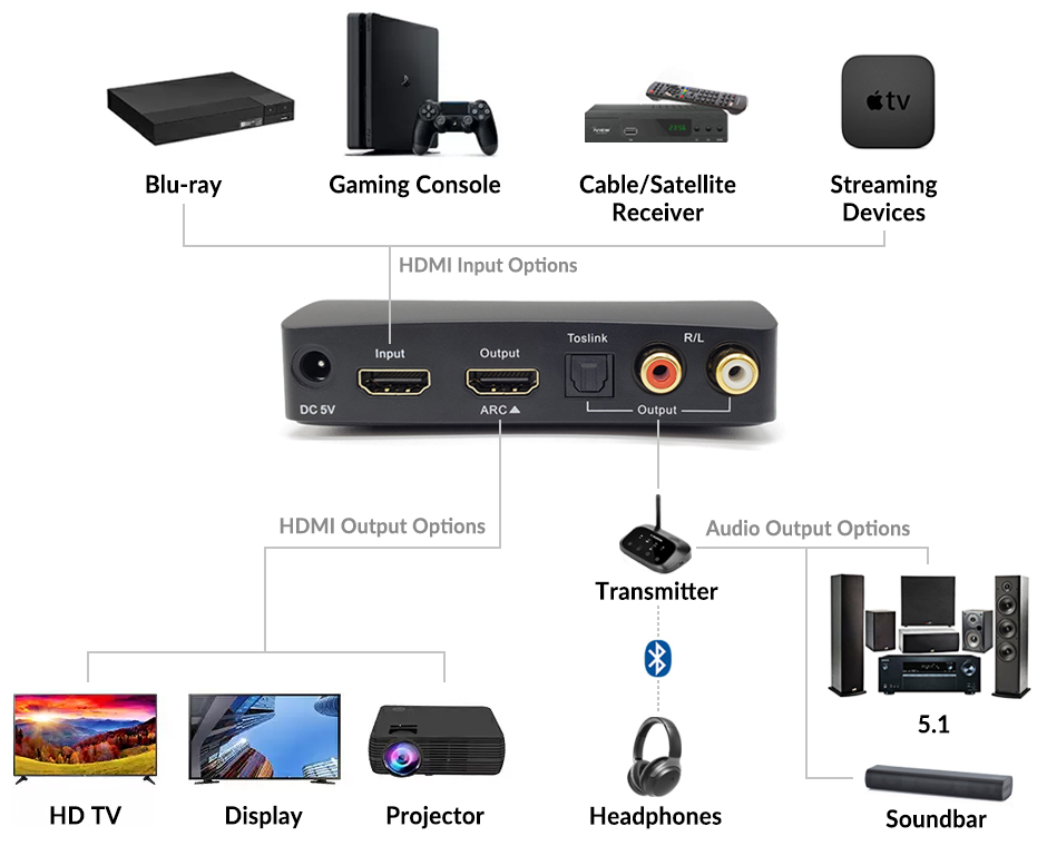
We are taking an example of the Avantree HDMI audio extractor here. Only the Toslink (optical) port on the adapter can work in this mode. Below mentioned steps are the ways of using the HDMI Arc adapter-

  • Connect the converter to the power source.
  • Take an HDMI cable and plug one end to the converter’s Arc port and the other end to the system’s Arc port. 
  • Plug the external speaker into the Toslink output port on the adapter. 
  • Click the Arc button. If the Arc indicator light turns green, then the job’s done.
1 hax04 multiple inputs video outputs audio outputs
Image credits: Avantree.com

Can I use HDMI ARC as a regular HDMI?

Seldom, our TV sets are labeled with “ARC” on the top of the HDMI port. ARC is an improved technology, and it refers to “Audio Return Channel.”. Arc helps in simplifying the system by sending the audio back to the TV.

All the HDMI cables can be utilized backward, i.e., we can use non-Arc ports. All HDMI cables are the same and perform similar functions. So if we plug in a generic HDMI cable to an HDMI Arc port, it will behave as regular HDMI. HDMI cables are all-in-one components that can switch in between standard HDMI and HDMI Arc.

Read more on…HDMI vs HDMI Arc: Exhaustive Comparison And Detailed Facts And FAQs

How do I know if my HDMI cable is ARC?

The cable is the same for regular HDMI or HDMI Arc. It is the ports that differ. If the HDMI port on the TV or the soundbar is marked with the “Arc” word printed on it, then we can identify the cable as an Arc cable. From 2009, most of the TVs have Arc port.

HDMI cables are just a specific type of wire. They don’t have any version or particular function such as Arc. Arc refers to the ports on the systems. HDMI cables come with standards such as 1.4, 2.0, or 2.1, etc. No cable is mainly designed for the “Arc” feature. We need to check if the TV port or the soundbar port is Arc enabled.

HDMI Vs HDMI Arc: Exhaustive Comparison and Detailed Facts and FAQs

hdmi0000

In this article, we are drawing a comparison of the regular HDMI vs HDMI Arc. HDMI Arc is the improved version of the generic HDMI cables that comes with additional features.

The key difference that separates HDMI and HDMI Arc is the transmission mode. HDMI cable only caters to video transmission while the HDMI Arc provides high quality audio transmission, similar to the working of an additional soundbar. Arc technology doesn’t require any new cable, it can be implemented upon any compatible HDMI.

What is HDMI? Explain

HDMI is abbreviated as “High Definition Media Interface”. It is one of the most preferred HD signal interfaces for transmitting both HD audio and video over just a single cable in commercial and home entertainment market.

We are able to connect a lot of devices such as TV, DVD, Bluray, Xbox, playstation and many more into our television through HDMI. In short, more and more AV devices can be connected through a simple effective HDMI cable. Even the corporate world is also moving towards HDMI for presentations, education, digital signage etc.

What is HDMI Arc? Explain

Often in new generation smart TVs, we can see a HDMI port written as “Arc”. This ARC is the abbreviation of Audio Return Channel. It is a newly launched protocol for HDMI devices. 

ARC accomplishes dual-way transmission of audio data via a single HDMI cable. The most important function of HDMI ARC is, it can send signals both upstream and downstream. Suppose, you want to watch the HD content of the OTT platforms on your smart TV. You can set up the TV and the soundbar with a single arc cable.

Draw a comparison between HDMI and HDMI Arc

Following are the major differences between regular HDMI and HDMI Arc-

ParameterHDMIHDMI Arc
Mode of TransmissionIt is suitable for videos.It is best suited for audio and video
ConnectivityIt cannot feed the audio back to the origin.It can work like a two-way audio transmitter cable.
Cable requirementRegular HDMI set-up requires more than one cable for overall connection.HDMI Arc cable is a single multipurpose cable that can pair with soundbar also.
CostThe cost of HDMI is average.HDMI Arc is very costly due to its improved features.

Read more about D flip flop Types

HDMI Vs HDMI Arc-FAQs

Is HDMI and HDMI ARC the same?

HDMI is the cable whereas Arc is a port or adapter. Both of the technologies require a HDMI cable in the first place. The Arc port is differently designed.

Nowadays, most of the HDMI cables are Arc-enabled. “High speed” printed HDMI cables generally support Arc function. If the HDMI port is labelled as “Arc” then we can identify it. If we connect a non-arc HDMI cable in Arc port, it acts as generic HDMI. 

Are all HDMI ports HDMI ARC?

Recently, all the HDMI ports come with Arc compatibility. But, we must read the user guide thoroughly to know if a particular device is Arc-enabled or not.

The use of HDMI Arc minimizes the need of using an extra optical cable for transmitting audio downstream. All HDMI ports are not Arc supported. We should also keep in mind that we cannot use any external device to convert regular HDMI to HDMI Arc. 

Do I need HDMI ARC for soundbar?

HDMI Arc is a very useful tool for making a home theatre like audio system using only one cable. The TV and the soundbar both must contain Arc compatible HDMI jack.

Through the HDMI arc soundbar, we can adjust the volume with our TV remote itself. For this set-up, we connect one end of the HDMI Arc cable to the TV port and the other end to the port of the soundbar. Thus we can establish the connection. While HDMI Arc is not a compulsory feature for the soundbar, it improves the sound quality.

Does HDMI ARC sound better?

HDMI Arc is regarded as the best option for high quality audio. Though optical cables provide satisfactory sound, HDMI Arc can be an even better choice for quality and minimized cable connection.

Still now most of the TVs use optical cables for sound transmission. But, if we want to hear top notch sound, we can use HDMI Arc. Also, some technologies like Dolby Digital Plus, DTS HD, True HD etc. don’t support optical cable. Only Arc can cater to the purpose. HDMI Arc supports every possible virtual audio format and sounds better than all.

xXUQLNrjWO9pzPtpSTKJ11tOzfnLOS6W7YYFzTOVm4TqtClmtN5ndCtcCncwz0VqjqRel pM03OLZpKr4p8UkhF3dD59r8 3FnJDfRLdWhRTSkwHSEMbV 3DzefvtSLc1iA8J7oL
Credits: Reliance Trends

Can The HDMI ARC Output On My TV Be Used As Normal HDMI?

We can definitely use HDMI Arc output on the TV as a generic HDMI. By connecting a simple HDMI cable into the Arc jack, we can make it function like the regular HDMI.

Sometimes any of the TV or the soundbar isn’t HDMI Arc enabled. In that case, we cannot get an Arc connection. In that case, if we connect normal HDMI cable in the Arc port, though it cannot provide high quality arc-like audio, it can yield regular sound. But we can not get an Arc facility with normal HDMI.

VGA vs HDMI:Exhaustive Comparison and Detailed Facts and FAQs

10983658213 fcaa77dcd0

VGA and HDMI are both display interfaces. Nowadays, HDMI is widely in use, where VGA is used in limited applications as VGA is the oldest display interface. 

This article will discuss the comparison between VGA vs HDMI in a detailed manner.

VGA HDMI Comparison:

VGA is the oldest display interface, and HDMI is one of the latest display interfaces, so lets compare these two technologies:

ParametersHDMIVGA
Stands For High Definition Multimedia Interface Video Graphic Array
Founded in HDMI was introduced at the end of 2002 VGA is the oldest digital interface introduced in 1987
Designed and Introduced byHitachi, Sony, Toshiba, Philips, Silicon Image, Panasonic, and Thomson.IBM
Signal HDMI uses digital signals for communication. HDMI uses digital data signal and VGA uses analog data signal, then transfer or transmission of data is more efficient in HDMI than VGA. and HDMI is easily completable with digital devices VGA uses analog signals for communication. New devices use a digital signal, so for using VGA cable digital to analog and  then analog to digital conversion required.
CompatibilityHDMI is compatible with DVI, VGA, etc, with converter.VGA to DVI and VGA to HDMI converter is also available
Resolution and Refresh rate HDMI with different versions, it can attain 8k (7680 X 4320) resolution with 120Hz refresh rate, but HDMI with 2K resolution it can achieve 480Hz refresh rate. The maximum resolution of a standard VGA is 640 X 480 with a 60 Hz refresh rate. Higher resolution can be attained with different versions of VGA.
ConnectorHDMI has 19 or 29 pins in its connector, there are five different types of connectors in HDMI, such as Type A, Type B, Type C, Type D and Type E.VGA only has 15 pins in the D-SUB connector and VGA BNC connector has a separate connector for each color and sync, such as Red, Blue, Green, Horizontal Sync, and Vertical sync.
Noise or InterferenceHDMI cables are less sensitive to crosstalk but can suffer from interference by electromagnetic fields.VGA cables are easily subjected to crosstalk and interference.
CableVGA cable cannot carry audio, and video signal with one cable, for carrying audio and video two different cables is required. HDMI cables carry Consumer Electronics Control (CEC) which enable user to control HDMI devices with a maximum of 15 devices.HDMI cable carries both video and audio signal through one cable simultaneously .
CostVGA is inexpensive, but converters from VGA to any other signal can cost more than that of a VGA cable.HDMI is relatively costlier than that of a VGA, but converters of HDMI to Other signal is cheaper.
LagHDMI apply post processing on the input signal which causes lag.VGA connections generally exhibit less input lag than HDMI connections because VGA does not apply post-processing on the (input) signal.
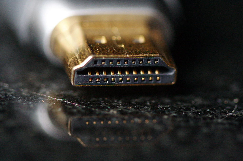
HDMI
Image Credit: “HDMI” by Sam-Cat is licensed under CC BY-ND 2.0

HDMI vs VGA quality

HDMI can transfer eight channels of uncompressed or compressed digital audio simultaneously

The quality of HDMI is better than that of VGA because HDMI uses an uncompressed or compressed digital signal. In contrast, VGA uses an analog signal, which creates a significant difference in quality.

Since HDMI uses an uncompressed connection, HDMI is independent of the various digital standards used by individual devices. It can carry high-quality multi-channel audio data and can carry all standard videos. HDMI is capable of carrying control and Status information in both directions, and as modern devices use digital signals, HDMI is easily compatible with them. HDMI allows managing pixel by pixel the native resolution of the screen with whatever the source devices.

VGA vs HDMI gaming

High-resolution and high refresh rates, all frame rates are required for a quality gaming experience for modern gaming.

The standard VGA is limited to 640 X 480 resolution and refresh rate of 60 Hz, which is not very much suitable with modern gaming standards. In contrast, the maximum resolution HDMI can attain 8K with a 120 Hz refresh rate which is very much ideal for every modern gaming experience.

Although the cables do not limit the refresh rate or resolution, they can be restricted by the source or connectors used. As HDMI is comfortable with digital devices, it is preferred over VGA because VGA Uses an analog interface which seems outdated nowadays. Only limited devices use an analog signal, so if it is not necessary to use VGA, always go for HDMI for gaming.

VGA vs HDMI resolution

HDMI was introduced in 2002 to improve existing connectivity standards by creating more miniature and better connectors which can summon tenuously transmit digital video and audio signals.

The standard VGA 640 X 480 resolution with 60 Hz refresh rate, whereas with a different version of HDMI, it can go up to 8K resolution with 240 refresh rate.

VGA’s maximum resolution can attend up to 2048 X 1536, but VGA does not prefer HDMI for high-resolution.

VGA vs HDMI
Image Credit: “Monitor” by davispuh is licensed under CC BY 2.0

VGA vs HDMI cable

Resolution and refresh rates are not limited to the cable but are determined by the source or device.

The quality of HDMI cables is much better than that of VGA cables, as VGA requires separate cables for audio and video, where HDMI can transfer audio and video simultaneously. HDMI cable is capable of up to 8 compressed or uncompressed digital audio channels, along with Consumer Electronic Control (CEC). 

13w3 to VGA cable
Image Credit: “13w3 to VGA cable” by gctwnl is licensed under CC BY-SA 2.0

The data in the VGA signal is analogous, so loss in data or interference in this type of signal is easy. With an increase in the length of the wire, the quality of the signal decreases. VGA Analogue data signal is also prone to noise and interference. HDMI uses transmission minimized differential signaling (TMPS), which can convert A picture automatically into the most appropriate format such as 16:9 or 4:3.

HDMI cable has16 wires that are wrapped in a single cable and carry a bandwidth of 5gbps. HDMI carries high-quality multi-channel audio data and can carry all standard formate of video. HDMI has three different channels for communication such as Display Data Channel (DDC), Transition-minimized differential signaling (TMDS) and Consumer Electronics Control (CEC).

Does VGA to HDMI reduce quality

VGA to HDMI converter is more expensive than the price of the VGA cable.

As the signal in VGA is analog and signal in HDMI Digital, when the conversion of the signal takes place, some loss of Signal quality happens, which can also introduce noise in the Signal.

During the conversion from VGA to HDMI, the analog signal is converted into a digital signal (using analog to digital converter), and running the VGA signal directly into an HDMI connector can cause damage. The connector as an analog signal has a higher voltage level, so a scaler or converter is required, which will take the VGA analog signal and audio signal to convert them into a digital signal (using digital to analog converter), which can be sent out to HDMI cable for connection.

Why does VGA to HDMI not work

Convert the signal between VGA and HDMI using a converter chip, where the converter chip is either designed to convert a VGA signal to HDMI or HDMI signal to VGA signal.

VGA to HDMI converter is not working causes can be:

  • The problem with the connector or port.
  • The malfunctioning signal from VGA to HDMI.
  • Check the power supply of the converter as VGA to HDMI converter requires external power for processing.
  • Check connection or lose connections.
  • Bad quality display can be caused by incorrect interference with the cable or faulty connector.
  • Restart the device after connecting as VGA is required to restart for better compatibility with the device.
  • New cables can be covered with a plastic cap so remove the plastic cap before using it.

Can VGA do 1080p 144Hz

Nowadays, only the older version of devices uses VGA port; otherwise, the newer ones use DisplayPort or HDMI.

VGA is not recommended for 1080p 144Hz, as it can adequately work till 1080p with a 60 Hz refresh rate, when the refresh rate increases beyond 60 Hz resolution decreases.

Original VGA cable can have a maximum resolution of 640 X 480 with a refresh rate of 60Hz; nowadays, 1080p is possible with VGA. The maximum resolution of VGA can be limited by signal source refresh rate also depends upon the signal source and display different modern connectors can easily achieve 1080p with 144 Hz.

Is HDMI better than VGA for 1080p

HDMI carries a digital signal where VGA has an analog signal that causes a significant difference between both the signals.

HDMI is recommended over for 1080p as VGA carries analog signal where HDMI carries digital in VGA at 1080p refresh rate is limited to 75 Hz at most, whereas with different versions of HDMI 240hz frequency rate can be achieved with 1080p resolution.

Standard VGA has a maximum resolution of up to 640 X 480, but with the latest technology, it is capable of 1080p. Still, the resolution and frequency rate can be limited due to the signal source or display.

Is HDMI sharper than VGA

Currently, HDMI is used with most devices as devices are compatible with digital signals, where is the use of VGA is very much limited.

HDMI has sharp images or videos, then VGA for higher resolution.

HDMI uses a digital interface that is able to carry video and audio 17 easily as HDMI uses digital signal which has many advantages over analog signal practically the difference in image quality is unnoticeable between HDMI and VGA. As VGA uses an analog signal, which can decrease image quality during transmission or conversion of the signal, noise or interference may occur incorrect translation of level may happen, as the length increases, the quality of signal decreases. The difference in quality VGA and HDMI is noticeable for higher resolution.

Can a VGA cable affect screen resolution

Connectors have 15 pins for VGA cable and VGA cables require separate cables for video and audio transmission. The source and quality of the cable can control the resolution of VGA.

Analog signal is not much immune to external noise, flickering, interference, etc. And with an increase in the distance, the quality of the signal degraded, which affects the overall resolution. Using a better quality VGA cable with a covering minimum length as possible may reduce noise and interference.

Do I need both VGA and HDMI?

VGA uses analog interference, whereas HDMI uses digital interference.

Display devices cannot use VGA and HDMI simultaneously, but display devices can change or switch between the cables if required.

Generally, VGA and HDMI are not required simultaneously. VGA is the oldest interface with display. The devices which still use the VGA port are very much limited, where the HDMI port is widely in use.

How can I increase my VGA resolution?

The standard VGA resolution is very much limited; it doesn’t support high-definition images or video.

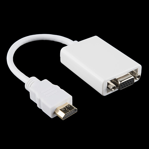
HDMI to VGA converter or adaptor can be used to get better resolution from the source for a better and sharper image or video for VGA connector.

HDMI to VGA Adapter
Image Credit: “HDMI to VGA Adapter” by SparkFunElectronics is licensed under CC BY 2.0

HDMI uses digital signal and can carry both audio and video conversion of HDMI to VGA converter will not improve the quality of the original signal, but for better transmission HDMI cable can be used instead of VGA cables. If Required but with HDMI converter will be needed, which will increase the overall expenditure.

Do monitors need a VGA cable

VGA is the oldest display interface, introduced by IBM in 1987.

Only an older version of monitors or devices have a VGA connector so the VGA cable can only be used for only older monitors or devices.

As VGA cable is much more intensive than other cables, it can be used when the budget is limited but not recommended with converters as the converter is more expensive than that of the VGA cable. If any device has an HDMI port, use an HDMI cable. If any device has a VGA port, then only use a VGA cable because using a converter also reduces the quality of the signal and using a converter increases the overall expenditure.

Does VGA to HDMI adapter work

HDMI adapter is used to convert the analog VGA signal into a digital HDMI signal.

If all the connections are correctly connected to the eye doctor and from the adapter, then the adaptor should work properly if their adapter is not faulty.

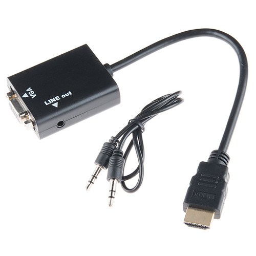
HDMI to VGA Adapter
Image Credit: “HDMI to VGA Adapter” by SparkFunElectronics is licensed under CC BY 2.0

Does VGA affect gaming

VGA uses separate cables for audio and video. It cannot transfer video and audio simultaneously through a single cable.

The slandered version of VGA is limited to 640 X 480 resolution with a 60 Hz refresh rate, which is not suitable for modern gaming standards. With many different versions of VGA, it can extend up to 1080p with a 60 Hz to 75 HZ refresh rate, which can limit the use of VGA in gaming.

VGA can affect the quality and can get interference, on lower quality of VGA cables and the image quality also may get affected. Several devices that produce or use analog signals had different refresh rates with different resolutions, the processor of the device must be able to process it as VGA cable does not limit the resolution or reference rate these are mainly limited by the source, but with higher refresh rate then limit can degrade the image quality.

Does VGA cause lag

More components or converters are connected in the path of the signal, and more lag is added to the signal as every component causes some degree of delay.

VGA has a relatively lower leg than HDMI because the VGA signal does not apply post-processing on the input.

Pipe Elbow Dimensions:Exhaustive Problems Solution and Facts

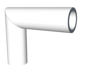
330px Mitre joint pipe 300x247 1

To change the direction of piping, pipe elbows are used. It is important to find pipe elbow dimensions for making a turn of desired radius.

This article discusses about different types of elbows and formulae to calculate their dimensions.

What is elbow in piping?

The path of piping is not always straight, it makes a turn at the end as required.


Elbows are the connectors between two pipes that are inclined at some angle. Elbow contains two openings at a specific angle where the pipes are fixed. Elbows usually come in 90 degrees, 45 degrees or 22.5 degrees.

What is the use of elbow in pipe fitting?

When there is a need to change the direction of fluid flow, the piping system needs to be bent.

This bent cannot be achieved directly by bending the PVC pipe as it is brittle in nature. An elbow is used which connects two straight pipes in angle. This way the direction of piping system is changed and hence the direction of fluid flow.

How do you calculate pipe length elbow?

To calculate the length of the pipe elbow, we need the distance between the ends of two pipes that need to be connected and the angle subtended by elbow.

Lets take an example of 90 degree pipe elbow for which pipe end distance (radius of elbow) is 300 mm.

Circumference of circle is given by-

Circumference = 2πr

90 degree elbow covers 0.25x circumference of circle. Hence, the length of pipe elbow- 0.25 x circumference of circle with radius 300mm.

What is the formula of 90 degree elbow?

Take off is defined as the length of material removed to make the pipe and fitting of a specified length.

The formula for 90 degree elbow is given below-

A = tan(45) x 1.5D X 24.5

Where,

D is diameter of elbow in inch

A is elbow center take off

What is the length of a 90 degrees elbow?

90 degrees elbow makes one quarter of a full circle. To find the length of 90 degrees elbow, we find the circumference of circle and then multiply it by 0.25.

The circumference of circle is given by the formula:

Circumference = 2πr

Hence the length of elbow becomes- 0.25 x circumference

What is the radius of pipe elbow?

On the basis of length of radius, elbows are classified into types- long radius elbow and short radius elbow. 

Radius of curvature is around 1.5 times the nominal diameter of the pipe for long radius elbows. On the other hand, radius of curvature is equal to the nominal diameter of the pipe for short radius elbows.

Short radius elbows are used where space limitation is there and abrupt change is required.

How do you measure 45 degrees elbow length?

A 45 degrees elbow makes 1/8 th of a full circle. Hence, the length of 45 degrees elbow will be equal to 0.125 times the circumference of circle.

If the radius of curvature is r, then circumference of circle is given by-

Circumference = 2πr

Where, the length of 45 degrees elbow will be

L = 0.125 x 2 x π x r

What is the formula of 45 degree elbow?

We have discussed above the formula for calculating take off for 90 degrees elbow.

For calculating take off length for 45 degrees elbow, we use the formula given below-

A = tan(22.5) x 1.5 D x 24.5

Where,

D is diameter of elbow in inch

A is elbow center take off

How many types of pipe elbows are there?

The pipe elbow can be classified on the basis of angle and the length of radius.

On the basis of angle subtended, the pipe elbows are classified as-

  • 90 degrees elbow
  • 45 degrees elbow
  • 180 degrees elbow

For special purposes, 60 degrees and 120 degrees elbows are also made.

On the basis of length of radius, elbows are classified as-

  • Long radius elbow- The radius of curvature is 1.5 times the nominal diameter of the pipe.
  • Short radius elbow- The radius of curvature is equal to the nominal diameter of the pipe, short radius elbows are used in places where space is very less.

How do I straight pipe my elbow?

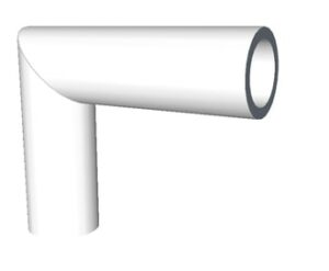
Miter bend is a type of bend in which the pipes are first cut at various angles and then joint together from ends to make an elbow in the piping.

A typical 90 degrees miter bend is made by joining ends of two pipes each cut at 45 degrees. These pipes are usually welded to each other.

Pipe elbow dimensions
Image: Miter joint

Image credits: Wikipedia

What is the take off for a 6 inch 90 degrees elbow?

The formula for 90 degrees elbow is-

A = tan(45) x 1.5 D x 24.5

Where,

D is diameter of elbow in inch

A is elbow center take off

Substituting D as 6, we get elbow center take off, A as 220.5

How do you join different size PVC pipes?

We can use reducers and bushings for connecting PVC pipes of different sizes.

  • For connecting a larger diameter pipe with smaller diameter pipe, we use a reducer to make a coupling.
  • For connecting a larger fitting to a smaller pipe, we use a reducing bushing.

The reducers and bushings come in various diameters.

Series Circuit Examples:Complete Insights and FAQs

R s 300x128 1

A series circuit has only one path for electric currents to travel through. In this type of circuit, all the different circuit components are linked in a single branch or path of the circuitry.

This article will discuss in detail different basic series circuit examples such as:

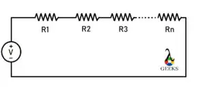
Resistor in Series

Suppose there is more than one resistor linked in a series circuit combination. In a series combination, the resistor is linked in such a way that the terminal of one resistor is connected to the terminal of the following resistor resulting in only one path for current to flow through.

The value of resistance increases with the increasing number of resistors in series combination. The current magnitude through each resistor remains constant, where is the voltage or potential drop across each resistor depends upon the magnitude resistance of each resistor.

If the resistors linked in the series are of identical values, then the potential drop across individual resistors will be identical, as the current flowing across each resistor is the same.

The equivalent resistance represents the overall resistance effect of the resistors in the series combination.

series circuit examples
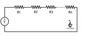
Fig. Series combination of ‘n’ resistors.

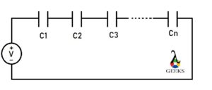
Capacitors in Series

Suppose there is more than one capacitor connected in such a way that the terminal of one capacitor is linked to the terminal of the following capacitor resulting in only one path for current to flow.

The overall capacitance decreases as the number of capacitors increases in a series combination.

C s
Fig. Series combination of ‘n’ Capacitors.

As the current magnitude through each capacitor is the same, the charge stored by each capacitor will be the same regardless of the value of the capacitor’s capacitance. At the same time, the potential drop across each capacitor will depend upon the value of each capacitor’s capacitance.

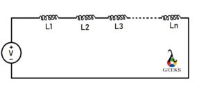
Inductor in Series

Suppose there is more than one inductor connected in a series combination such a way that one terminal of the inductor is connected to another terminal of the inductor resulting in only one path for current to flow.

The voltage or potential drop across individual inductors is not equal, whereas the current flowing through individual inductors is identical in the series combination.

L s
Fig. Series combination of ‘n’ inductor.

The total or equivalent inductance is the summation of the individual inductance of each inductor connected in series as the number of turns of coils increases with the addition of the inductor.

Resistor and Capacitor in series

Resistor and capacitor can also be linked in a series combination with each other.

If there is at least one resistor and one capacitor connected in series with each other, then the resulting circuit will be first-order circuitry.

The overall importance of the RC series circuit

gif 5

Where is Z is the overall impedance

R is the resistance of the resistor

XC is the impedance of the capacitor

The phase angle of the RC series circuit is

gif 1
File:AC RC series circuit.svg
Image Credit: “File:AC RC series circuit.svg” by P1ayer is marked with CC0 1.0

In this RC series circuit, the overall voltage lags current, the angle between voltage and current depends upon the value of resistance and the impedance generated by the capacitor.

Resistance and Inductor in series

The resistor and inductor can also be connected in a series combination with each other.

When there is only one resistor and one inductor in the circuitry, it is the first-order RL circuit.

The overall impedance of the RL series circuit is

gif 2

Where R is the resistance of the resistor

And XL is the impedance generated by the inductor.

The phase angle of the RL series circuit is equal to

gif 3

The overall voltage leads to current in the RL series circuit, and the angle between the voltage and current depends on the value of the resistance and impedance generated by the overall circuitry.

RLC (Resistance, Inductor and Capacitor) Series 

In an RLC series circuit, at least one resistor, one capacitor, and one inductor are connected in series combination with each other.

The current across each circuit element in the series combination is the same. Still, the total or overall voltage is split across each component’s voltage magnitude depending upon each component’s electrical characteristics.

RLC series is a resonant circuit that resonates at a specific frequency which is called the resonance frequency.

If the inductor impedance is greater than that of the capacitor’s impedance, then the overall circuit voltage leads to current. If the capacitor impedance is greater than the impedance of the inductor, then the overall circuit voltage lags current by some angle. In both cases, the angle value depends on the resistance and impedance generated by the inductor and capacitor.

The overall impedance of RLC series circuit :

gif 4

The phase angle of the RLC series circuit is equal to

gif 5

LC  (inductor and capacitor) Series

Pure inductor and capacitor can be connected in a series combination. There must be at least one inductor and one capacitor in this combination.

As both the elements are connected in series with each other, the current flowing through each element will be the same, and the overall voltage will be simply the summation of the voltage drop across the capacitor and the inductor.

The total (or overall) impedance of the circuitry is the summation of the impedance of capacitor and inductor in the LC (inductor and capacitor) series circuit.

The overall impedance Z = ZL+ ZC

where

gif 7

then

gif 6
File:Tuned circuit animation 3.gif
Image Credit: “File:Tuned circuit animation 3.gif” by Chetvorno is marked with CC0 1.0

Voltage in Series

The current source cannot be combined in a series but can be combined in parallel as the series combination of current sources violates Kirchhoff’s current law.

For example, two voltage sources are linked in a series combination. When the voltage source’s positive terminal is linked together with the negative terminals of the voltage source, the overall voltage combination will be added.

In contrast, when the positive terminal of the voltage source is connected to the negative terminal of another voltage source, then the combination’s overall voltage will subtract from each other; this is based on the sign convention of the voltage source or the direction of the flowing current in the circuitry.

If there is more than one current source connected between two circuit nodes, then the current source is in parallel combination.

FAQ:

Why do we connect circuit in series

The series circuit can be a combination of different circuit elements such as resistance, capacitor, inductor, etc.

When the constant current is required, the series combination is used as the current’s magnitude remains consistent in the series combination, which can be controlled or changed easily.

How does voltage changes in a series circuit

Series circuit is also known as a voltage divider circuit as the overall potential energy gets split into all circuit components.

As the current throughout the series circuit is constant, the value of voltage depends upon the impedance or resistance generated by each circuit element connected in the series combination. That is how the value of voltage changes with the electrical property of each component.

What is the advantage of series circuit?

There are several advantages and disadvantages of a series circuit combination depending on the application or where it is used.

The components connected in a series combination have the same magnitude of current flowing through it. All the components connected in series can be turned on or off by using only one switch. The circuit combination does not get overheated easily, and the circuitry design is very simple relative to the parallel circuit.

Firing Order And Firing Interval: 7 Facts You Should Know

Vengine numbering 1

Firing order and firing interval have different meanings.

Firing order is the sequence in which the cylinders inside a multi cylinder engine are fired whereas firing interval is the time duration after which the same spark plug (cylinder) gets fired. Firing interval can be used in a single cylinder engine as well whereas firing order exists only when there are multiple cylinders used.

What is firing order?

Firing order helps reducing the chances of vibrations and regulates proper heat transfer.

As discussed in above section, firing order is the sequence with which cylinders inside the engine are fired. This term comes into play when there are multiple cylinders inside an engine.

Firing order of multi cylinder engines

Firing order means the chronology with which the cylinders are fired.

Below are some of the common firing orders used for different types of multi cylinder engine-

Number of cylindersFiring orderEngines using respective firing order
21-2Buick Model B
31-3-2Perodua Kancil engine
41-3-4-2,1-2-4-3Ford Taunus, Ford Kent
51-2-4-5-3,
1-3-5-4-2
Volvo 850, GM Atlas Engine
61-5-3-6-2-4,
1-4-3-6-2-5
Nissan L engine, Volkswagen V6s
71-3-5-7-2-4-6Radial engine
81-8-7-3-6-5-4-2,
1-8-7-2-6-5-4-3
Nissan VK engine, GM LS engine
91-10-9-4-3-6-5-8-7,
1-6-5-10-2-7-3-8-4-9
Dodge Viper V10, BMW S85, Ford V10
Table: Firing orders of multi cylinder engines with examples
Firing order and firing interval
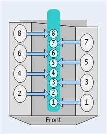
Image: Numbering of cylinders in multi cylinder engine

Image credits: Wikipedia

What is firing interval?

Firing interval is the time between two successive firings of same cylinder/spark plug.

The spark plug has to fire during the ignition stroke. Firing of the spark plug is so precisely timed that it automatically fires when its the time for ignition stroke. If it takes x milliseconds to complete one full cycle then after every x milliseconds, firing takes place.

What is the significance of firing interval?

Anything which is more systematic and more even works more efficiently.

The significance of firing interval is as follows-

  • Minimizes vibrations.
  • Provides increased number of even pressure pulses.
  • Uneven firing interval causes throaty and growly sound in engines

What happens if firing order is not maintained?

The cylinders are fired in a particular sequence because of vibrations and heat transfer issues.

If the firing order is not maintained, lets say, if adjacent cylinders keep firing for a long time. Then the heat generated inside the engine will be very high and high sink temperature is always less efficient. The vibrations from the adjacent cylinders will have serious impact on bearings supporting the crankshaft.

Hence, a proper firing order is desirable.

How is firing order controlled/set?

The firing order is controlled by the ignition system of the engine. It provides necessary current to specific cylinders at specific times when ignition is required.

The distributor controls the spark in each spark plug of a multi cylinder engine in correct order. Changing the distributor position will directly affect the firing order of the engine. But this work needs to be done by expert mechanic. Changing of firing order is not recommended.

How is firing interval controlled/set?

The ignition system of the engine also controls the firing interval. It gives the spark at exact moment when required.

Firing interval is controlled by the action of cam which acts as circuit breaker. When the circuit breaker is open, capacitor starts charging creating a high voltage surge in the circuit. This high voltage surge creates the spark. The cam rotation is perfectly timed in a manner such that it breaks the circuit at the precise moment.  

Different parts used in controlling firing order and firing interval

The ignition system of the vehicle controls the firing order and firing interval of the engine. Most commonly used ignition system is magneto and battery ignition system.

In a magneto ignition system, following parts are used-

  • Magneto– A rotating magnet that controls the voltage.
  • Distributor– It distributes the current to the spark plugs in a correct sequence.
  • Capacitor– Capacitor are nothing two parallel metal plates whose each end is connected to circuit. It is used for storing charge
  • Spark plugs– Spark plugs are responsible for igniting the air fuel mixture.

Magneto itself generates power for the ignition system. Hence, it does not need any external source of power. In battery ignition system, batteries are used as external power source.

Two Surge Protectors In One Outlet: Essential Guidelines

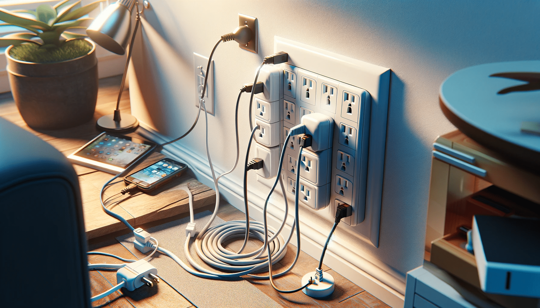
two surge protectors plugged into one outlet

This article elucidates what happens if we keep Two Surge Protectors In One Outlet. The power devices are susceptible to voltage surges. So we utilize surge protectors to avoid any unwanted electrical mishap.

Is it safe to install Two Surge Protectors In One Outlet? If we maintain the current limit of the socket, it is totally fine. Even Two Surge Protectors In One Outlet can serve as extra protection over a single one if connected in parallel. Both the surge protectors will work as backup for each other.

What are the surge protectors? 

A surge protector or a surge suppressor is an electrical device that provides protection to electrical appliances from voltage surges.

Fluctuations in electricity supply can cause sudden changes in voltage in home distribution. They are called spikes. If a spike lasts for a long time, we call it a surge. A surge can be harmful to delicate electronic devices. A surge protector is beneficial in protecting the appliances against voltage surges.

Read more about voltage…..Can voltage be negative: When, How, Exhaustive FAQs, insights

Why do we use surge protectors?

A voltage surge can cause permanent damage to electrical circuits. A surge protector is efficient in preventing voltage or power surges. It has more functions also.

There are two primary reasons behind using a surge protector. Firstly, a surge protector can accommodate multiple components in one single power socket. Secondly, a surge protector shunts the extra electricity through a semiconductor material to a grounding wire whenever it senses any surge.

How does a surge protector work?

Power surges damage electronic components or even lead to their untimely failure. A surge protector guards by passing current to the equipment plugged into it. The central part of a surge protector is a MOV.

The MOV acts as a pressure sensing valve. Whenever there is a sudden surge or spoke in the current, the MOV senses it. It brings down the resistance when there’s high voltage. Similarly, in low voltage, it increases resistance. The surge protector diverts extra current through the grounding wires of the outlets.

Two Surge Protectors In One Outlet- FAQs

Is it safe to overload surge protectors?

We should perform overloading of surge protectors carefully. We should keep in mind the rating given on the surge protector. 

Surge protectors are designed to incorporate devices that draw little current. It is not recommended that we use surge protectors for high amperage appliances like fridges, heaters, microwaves, etc., as they are heavy power users. However, we must not exceed the capacity of the power strip.

What are the necessary conditions to plug in Two Surge Protectors In One Outlet?

Plugging two surge protectors in one outlet is a pretty safe approach. To ensure better safety, one can use outlets that support a multi-device set-up (e.g., duplex socket).

However, some safety measures need to be followed-

1. We should never connect a lot of devices with both the surge protectors. The combined load of them may overload and burn them.

2. We should put the surge protectors in series so that if somehow one fails, the other one compensates for the entire load.

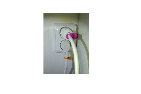
Two Surge Protectors In One Outlet
Credits: Quora

Can we plug an extension cord into a surge protector?

Although we run a risk of catching fire if we plug an extension cord into a surge protector or reverse, the phenomenon isn’t impossible. We can push the extension cord plug to the outlet of the surge protector.

With correct gauge and ampacity, daisy-chaining extension cords and surge protectors can be performed with overloading and fear of electrical hazards. But if any of the devices are improper or weak, the process can really turn into danger. Ratings of both of them must be equal.

Is it possible to plug two surge protectors?

It is not at all an illegal method to plug one surge protector into another. Though, this is often regarded as a hazardous task due to the fear of overload.

Surge protectors contain a Metal Oxide Varistor (MOV). When it fails during any surge, the protector loses its capability. So, if we plug in another surge protector, then that acts as protection and prevents any mishap. Surge protectors with failure indicators are even better. They don’t get destroyed.

How to daisy chain surge protectors? 

Daisy-chaining surge protectors are often believed to be malpractice. Daisy chain means the connection of equipment in series. Daisy chains can lead to power overload and fire.

Along with the warnings, it is also a bad idea to daisy chain surge protectors. There are some expensive surge protectors that come with a sensing circuit. It monitors the entire circuitry and indicates surges through the LED. The use of these types of surge protectors can be useful if we want to daisy chain them.

Is a surge protector the same as a fuse?

It is a very common misconception that a fuse or a circuit breaker is the same as a surge protector. But a surge protector is a completely different product.

The main difference between a fuse and a surge protector is, the former protects a circuit from excess current while the latter protects from excess voltage. A fuse blows away in a very high current. The surge protector bypasses any voltage surge through low resistance, and it doesn’t get burnt as well.

Coolant vs Refrigerant: 7 Important Factors Related To It

Refrigerant 199x300 1

Coolant and refrigerant are not entirely different. This article discusses about the topic Coolant vs Refrigerant in detail.

Coolant is a broad term and refers to a fluid that absorbs heat from the system. This way the temperature of the system can be regulated. When the temperature needs to be reduced below ambient temperature, then the coolant is referred as a refrigerant. Hence, all refrigerants are coolants in broader sense.

Definition of coolant

As discussed above, coolant can be any fluid that is used to remove heat from the system and reduce the temperature of the system.

The coolant can work without changing its phase (whether liquid or gas) or by changing its phase (liquid to gas and gas to liquid).

Uses of Coolant

A coolant is used in places where the temperature needs to be regulated. Excess heat can create a lot of problems in engines, machine components etc.

Different places where coolant is used are-

  • Inert gases are used as coolants in nuclear reactors.
  • Vehicle engines use cooling fluid/ water jackets around engine to absorb the excess heat generated in the cylinder.
  • Rocket engine nozzles have small tubes through which liquid oxygen is passed that cools the nozzle to a desired temperature, without which the metals used in nozzle wouldn’t have survived the high temperature generated because of exhaust gases.

Types of coolant

Coolant comes in various forms and phases. It is important to know the nature of coolant because an improper coolant will not be able to regulate the temperature of the system to required value.

The different types of coolants used in industry are-

  • Gaseous- Hydrogen, Boron, Sulfur Hexafluoride are commonly used gas coolants. Hydrogen is used in turbogenerators, Boron in nuclear reactors and Sulfur Hexafluoride in switches, transformers or other kind of circuit breakers etc.
  • Two phase- These types of coolants uses both the phases of coolant that is liquid and gas. These coolants are usually used in applications where desired temperature is below ambient temperature. These coolants are called as refrigerants.
  • Liquids- Water is the most common liquid coolant. But it cannot be used while dealing with metals due to corrosive nature of metals. Various mineral oils are used as coolant in place of water to cool machine components. For example, special oil is used to cool the job while machining on lathe.

Definition of refrigerant

Refrigerants are the coolants that are used in low temperature applications. Refrigerants use their latent heat of vaporization to reduce the temperature to significantly low value.

Refrigerants bring with them a lot of environmental concerns which is why there are many rules and regulations of refrigerants.

Refrigerant
Image: Refrigerant

Image credit: Stephanie~commonswiki, Can of DuPont R-134a refrigerantCC BY-SA 3.0

How do refrigerants cool the system?

Refrigerants absorb heat and change their phase to achieve the desirable temperature. Some gas cycles may use only one phase of the refrigerant for example Bell Coleman cycle or Reverse Brayton cycle.

In a typical refrigeration cycle, the refrigerant enters the system in liquid form. It absorbs the heat from the system and gets converted into gaseous form. Later on, the gaseous refrigerant is converted back to liquid state so that it can be used again.

Coolant Vs Refrigerant
Image: The observed stabilization of HCFC concentrations (left graphs) and the growth of HFCs (right graphs) in earth’s atmosphere.

Image credits: Wikipedia

What are desirable properties of refrigerants?

The use of refrigerants is regulated due to their toxic and inflammable nature. They also give out green house gases which are harmful for ozone layer.

Due to above reasons, some refrigerants are banned. An ideal refrigerant has following properties-

  • Non toxic
  • Non corrosive
  • Non flammable
  • No green house gas emission and ozone layer depletion potential.
  • Freezing point below the target temperature.

Is AC coolant and engine coolant same?

Both AC coolant and engine coolant are used for cooling. But their applications and mechanism differ from each other.

Water is typically used as engine coolant. It cools down the engine by absorbing heat and transferring it to the outside air and also transfers heat to the cabin of the vehicle when vehicle heating feature is turned ON. It is mixed with anti freeze substances so that the water does not get frozen. AC coolant is used for absorbing heat from the cabin and emitting out to the atmosphere. The AC coolant will change its phase from liquid to gas and back to liquid.

Hence, the major difference between the two is the application (one is used to cool engines and other is used to cool the cabin) and other difference is the mechanism of cooling (engine coolant does not change its phase whereas AC coolant switches its state from liquid to gas time to time).

Saturated Liquid vs Subcooled Liquid: 3 Critical Facts

Article 3 image 1

Saturated Liquid VS Subcooled Liquid: Need to know Critical Facts

Saturated liquid and subcooled liquid are the different stages during the phase change process of a pure liquid. The principal phases of a pure substance are Solid, Liquid, and Gas.

Subcooled liquid refers to that phase of a substance where it exists in liquid form at a temperature below its boiling point at the system pressure. The saturated liquid is a liquid that is about to vaporize, which means any decrease in pressure without changing its temperature causes it to boil.

Saturated Liquid Vs Subcooled Liquid

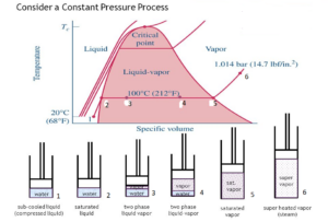
Image Credit: Saturated liquid Vs Subcooled liquid https://s3.studentvip.com.au/notes/11438-

Any liquid, whether in its pure form or in a mixture exerts a specific pressure over the surface of the liquid at a particular temperature, which is called the vapor pressure of the substance at that temperature. If the temperature of the liquid increases, its vapor pressure also increases. As this vapor pressure equals the pressure of the surrounding atmosphere, the liquid starts to boil. The liquid at its boiling point is called a saturated liquid.

For example, water is a saturated liquid at its boiling point of 100°C under the atmospheric condition at Sea level or 1-atmosphere pressure. As water is cooled below 100°C, it becomes sub-cooled. As the pressure is increased beyond 1 atmosphere, the boiling point of water increases, or it becomes a sub-cooled liquid at 100 °C.

Subcooled liquid example

Any liquid below its boiling temperature at a given pressure can be considered as a Subcooled liquid.

Water boils at 373 °K(100° C). Now water at room temperature293°K(25°C) andat normal atmospheric pressure is an example of a Subcooled liquid.

Certain conditions that cause a liquid to be Subcooled are:

At a given system pressure when the liquid attains a temperature lower than its saturation temperature. When the liquid is at a pressure higher than its saturation pressure at the given temperature. Thermodynamically the liquid has lower enthalpy and Specific volume than that of a saturated liquid.

Article 3 image 1

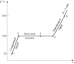
Image credit: T-v diagram representing phase change for water at constant pressure https://engineering.purdue.edu/CFDLAB/class/me200/filesFall2010/me200_notes_f10_week3.pdf

Some other examples of sub cooled liquid are:

  • Liquid ammonia at a temperature below -33.3°C and pressure 1 bar or higher.
  • Liquid ammonia at a temperature below -50°C and pressure 0.41 bar or higher.
  • Ethylene glycol at a temperature  below 197 C and pressure 1 bar or higher
  • Ethyl alcohol at a temperature below 77.8 C and pressure 1 bar or higher.

As can be seen above, in the example of liquid ammonia, it can exit in sub-cooled conditions at different conditions of pressure and temperature. -33.3°C is the saturation temperature of ammonia at 1 bar pressure. Similarly, for a temperature of -50°C, the corresponding saturation pressure for ammonia is 0.41 bar (approx).

Subcooled liquid pressure

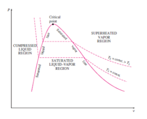
A liquid with a pressure higher than its saturation pressure at the given temperature is said to be a Sub-cooled or Compressed liquid.

Sub-cooled liquid means that the temperature of the liquid is lower than the saturation temperature for that particular pressure and a compressed liquid means that the pressure of the liquid is superior than the saturation pressure for the given temperature. Both the terms can be used alternatively.

Since liquids are incompressible in nature, their properties are relatively independent of pressure. Subcooled liquids are defined by:

  • Higher pressure than a saturated liquid(P>Psatat a given T)
  • Lower temperature than a saturated liquid(T<Tsat at a given P)
  • Lower enthalpy than a saturated liquid(h<hfat a given T or P)
  • Lower internal energy than a saturated liquid(u<ufat a given T or P)
  • Lower specific volume than a saturated liquid (v<vf at a given T or P)

Enthalpy is mostly affected by pressure, a more accurate relationship for h

hf~hf@T+vf(P-Psat)

pv

Image Credit:P-V Diagram of a pure substance http://processandinstrumentation.blogspot.com/

Frequently Asked Questions

Q. What is the difference between Saturated and Subcooled liquid?

Ans:Thoughboth Saturated liquid and Subcooled liquid are the two phases of the same liquid, they are quite different from each other.

Subcooled is the condition where the liquid is colder than the minimum temperature (saturation temperature), which is required to keep it away fromboiling. On the contrary saturated liquid is the condition when the liquid is almost at its boiling point.

In the case of saturated liquid, if the pressure is further lowered andkeeping the temperature constant, the saturatedliquid will start to boil. On the other hand, the liquid will besub-cooled if pressure is increased beyond its saturated pressure at its boiling point.

Q. Why is sub-cooling desirable in a refrigeration system?

Ans:A sub-cooled liquid increases the energy efficiency of a refrigeration system as it has lower specific volume

The refrigerant is sub cooled in the condenser to avoid the early vaporization of the refrigerant before heading towards the expansion device.

If proper condenser surface area is not provided to ensure proper subcooling, the refrigerant may partially evaporate in the piping as it moves to the expansion device. If the refrigerant partially evaporates before entering the expansion device, it will require higher refrigerant volume to be pumped to achieve the same cooling. This increases the pumping cost and hence the energy consumption.