Outrunner vs Inrunner: A Comprehensive Technical Guide for Electronics Students

outrunner vs inrunner

When it comes to electric motors, the choice between outrunner and inrunner configurations is a crucial decision for electronics students. These two motor types have distinct advantages and disadvantages, and understanding their technical specifications is essential for designing and implementing efficient electrical systems. This comprehensive guide will delve into the intricate details of outrunner and inrunner motors, providing electronics students with a thorough understanding of their performance characteristics, theoretical principles, and practical applications.

Inrunner Motors: High-Speed Efficiency

Inrunner motors, also known as “in-hub” or “spindle” motors, are characterized by their rotor positioned inside the stator. The stator consists of multiple permanent magnets, while the rotor contains copper windings. This unique configuration offers several advantages:

  1. High RPM Capability: Inrunner motors are capable of reaching exceptionally high rotational speeds, making them ideal for applications that require rapid movements, such as drones and high-speed RC vehicles.
  2. Efficient Heat Dissipation: The close proximity of the windings to the air-cooled exterior of the motor allows for efficient heat dissipation, improving overall efficiency and performance.
  3. Compact Design: Inrunner motors have a more compact and lightweight design compared to their outrunner counterparts, making them suitable for applications where space and weight are critical factors.
  4. High-Speed Performance: The high-speed capabilities of inrunner motors make them well-suited for tasks that demand rapid acceleration and precise control, such as in robotics and industrial automation.
  5. Lower Torque Output: While inrunner motors excel in high-speed applications, they generally have a lower torque output compared to outrunner motors.

Outrunner Motors: High-Torque Powerhouses
outrunner vs inrunner

Outrunner motors, also known as “external rotor” or “hub” motors, have the rotor positioned outside the stator. The stator consists of copper windings, while the rotor contains permanent magnets. This configuration offers several distinct advantages:

  1. High Torque Output: Outrunner motors are designed to provide exceptional low-RPM torque, making them ideal for applications that require high-torque, low-speed performance, such as electric bicycles and electric scooters.
  2. Larger Diameter: Outrunner motors typically have a larger diameter compared to inrunner motors of similar power output, allowing for a more efficient conversion of electrical energy into mechanical energy.
  3. Lower RPM Capability: While outrunner motors excel in low-speed, high-torque applications, they generally have a lower top speed compared to inrunner motors.
  4. Less Efficient Heat Dissipation: Due to their larger size and the increased distance between the windings and the air-cooled exterior, outrunner motors can be less efficient in dissipating heat, which can impact their overall performance at higher RPMs.
  5. Bulkier Design: Outrunner motors have a larger and heavier design compared to inrunner motors, which can be a consideration in applications where size and weight are critical factors.

Technical Specifications Comparison

To further understand the differences between outrunner and inrunner motors, let’s delve into their technical specifications:

Specification Inrunner Motors Outrunner Motors
Size and Weight Compact and lightweight Larger diameter and heavier
Speed and Torque Higher RPM capability, lower torque output Lower RPM capability, higher torque output
Efficiency Generally more efficient due to compact design and efficient heat dissipation Can be less efficient, especially at higher RPMs, due to larger size and less efficient heat dissipation
Applications Ideal for high-speed applications (e.g., drones, RC cars) Suitable for high-torque, low-speed applications (e.g., electric bicycles, electric scooters)

Theoretical Principles and Electronics Formulas

The fundamental principle governing the operation of both inrunner and outrunner motors is the principle of electromagnetic induction. This principle states that a voltage is induced in a conductor moving relative to a magnetic field, which is the foundation for the operation of all electric motors.

The formula for calculating the power (P) of an electric motor is:

P = τ × ω

Where:
– P = Power (Watts)
– τ = Torque (Nm)
– ω = Angular velocity (rad/s)

This formula demonstrates the relationship between power, torque, and angular velocity, which is crucial for understanding the performance characteristics of both inrunner and outrunner motors.

Practical Examples and Numerical Problems

Let’s explore some practical examples and numerical problems to further illustrate the differences between inrunner and outrunner motors.

Example 1: Calculating the power of an inrunner motor
Given:
– Torque (τ) = 0.1 Nm
– Angular velocity (ω) = 500 rad/s

P = τ × ω
P = 0.1 Nm × 500 rad/s
P = 50 Watts

Example 2: Calculating the torque of an outrunner motor
Given:
– Power (P) = 100 Watts
– Angular velocity (ω) = 200 rad/s

P = τ × ω
100 Watts = τ × 200 rad/s
τ = 0.5 Nm

These examples demonstrate how the power formula can be used to determine the power and torque characteristics of inrunner and outrunner motors, respectively.

Figures, Data Points, and Measurements

To provide a visual representation of the differences between outrunner and inrunner motors, consider the following figures, data points, and measurements:

  1. Size Comparison:
  2. A 500W outrunner motor may have a diameter of 60mm, while a 500W inrunner motor may have a diameter of 40mm.

  3. Weight Comparison:

  4. A 500W outrunner motor may weigh 1kg, while a 500W inrunner motor may weigh 0.5kg.

  5. Speed and Torque Curves:

  6. Inrunner motors typically have a higher RPM capability and lower torque output, while outrunner motors provide better low-RPM torque and lower top speeds.

These data points and measurements can help electronics students visualize the physical and performance differences between outrunner and inrunner motors, aiding in their understanding of the technical specifications and practical applications of these motor configurations.

Conclusion

In the world of electric motors, the choice between outrunner and inrunner configurations is a crucial decision for electronics students. Inrunner motors excel in high-speed applications, offering efficient heat dissipation and compact design, while outrunner motors are better suited for high-torque, low-speed tasks, with their larger diameter and higher low-RPM torque output.

By understanding the technical specifications, theoretical principles, and practical examples of these two motor types, electronics students can make informed decisions when designing and implementing efficient electrical systems. This comprehensive guide has provided a detailed exploration of the key differences between outrunner and inrunner motors, equipping you with the knowledge and tools necessary to navigate the world of electric motor technology.

References

  1. In-runner VS Out-runner .. inherent Advantages/Disadvantages – Endless Sphere Forum
  2. Inrunner vs. Outrunner – RCPowers Forum Discussion
  3. Inrunner vs. outrunner – RC Groups
  4. Inrunner Vs Outrunner – Reacher Technology Co.,Ltd
  5. Outrunner vs inrunner motors – Reddit

Adiabatic Vs Isothermal: Exhaustive Comparative Matrices And Detailed Facts

image 37

Both Adiabatic and Isothermal processes are integral part of thermodynamics but both of them are totally different from each other.

An Adiabatic process undergoes in such a way that no heat enters or leaves the system during the whole process i.e.

image 37

An Isothermal process is a process where temperature remains constant throughout the whole process i.e.

image 38

Adiabatic vs Isothermal Process

The major differences between Adiabatic and Isothermal process are listed below:

Adiabatic ProcessIsothermal Process
Heat transfer takes place during the process.No any transfer of heat and mass during the process.
Temperature remains constant.Temperature of an adiabatic process changes due to internal system variation.
Work done is due to the net heat transfer in the system.Work done is mainly the outcome of change in internal energy inside the system.
Transformation occur in the system is very slowTransformation occur in the system is very fast.
To maintain the temperature constant , addition and subtraction of heat take place.There is no any change in heat, so no any addition or subtraction of heat take place

Adiabatic curve vs Isothermal curve

Certain differences can be observed in between Adiabatic and Isothermal processes depending on the changes occur in pressure, volume, temperature etc. during the process.

Adiabatic curveIsothermal curve
This curve is a representation of the relation between pressure and volume of a given mass of gas when there is no change  in temperature during the whole process.This curve is a representation of the relation between pressure and volume of a given mass of gas when there is no transfer of heat throughout the whole process.
It is represented by the equation PV=constant It is represented by the equation, This image has an empty alt attribute; its file name is image-39.png
  
adiabatic vs isothermal
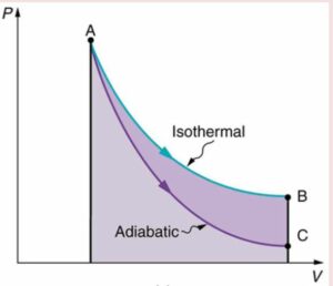
P-V diagram of Isothermal and Adiabatic path

Image Credit: lumenlearning

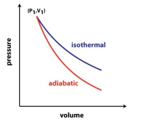
In the above figure both Isothermal and Adiabatic curves are plotted. Both the processes Isothermal

This image has an empty alt attribute; its file name is image-38.png

and Adiabatic (Q=0) start from the same point A. In case of Isothermal process to maintain the temperature constant, heat transfer takes place between the system and the surrounding due to which during the Isothermal process more work has to be done.

Pressure remains higher in Isothermal process than the adiabatic process generating more work.The final temperature and pressure for the Adiabatic path(point C) is below the Isothermal curve indicating a lower value though the final volume of both the processes are same.

Adiabatic Expansion vs Isothermal Expansion

article 14 2
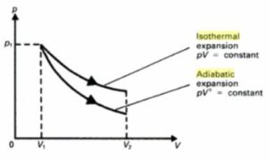
P-V curves for Adiabatic Vs Isothermal Expansion

Image Credit: A_level_Physics

In the above figure represents the isothermal and adiabatic expansion of an ideal gas which is initially  at a pressure p1.

For both Adiabatic and Isothermal expansion volume starts at Vand ends at V2 (V2> V1). If we integrates the curves in the figure above , we will get positive work for both the cases which implies work done is done by the system only.

In case of Expansion process, Wisothermal>Wadiabatic .

That means Isothermal expansion does greater work than Adiabatic expansion.

Work done in an adiabatic process ,

article 14 3 1

Work done in an Isothermal expansion process

A 14 6

 In adiabatic expansion work is done by the gas which implies work done is positive, since Ti >Tf  the temperature of the gas goes down. The final pressure obtained in an Adiabatic expansion is lower than the final pressure of Isothermal expansion. The area under the isothermal curve is larger than that under the adiabatic curve which implies more work is done by the isothermal expansion than by the adiabatic expansion.

.

Adiabatic vs Isothermal Humidification

In both adiabatic and isothermal humidification processes, approximate 1000 BTU’s per pound (2.326 KJ/kg) of water are necessary to transform water from a liquid to a vapour.

Humidification occurs when the water has absorbed enough heat to evaporate. Two common  methods of humidification used are: isothermal and adiabatic. In isothermal humidification, boiling water is the main source of energy. In adiabatic humidification, surrounding air is used as the source of energy.

 In adiabatic humidification, the air and water is in direct contact, which is not heated. Generally a wetted medium or a spray mechanism is required to spray water directly in to the air and heat from the surrounding atmosphere causes the evaporation of water.

In Isothermal humidification, steam vapour is produced from external energy and steam is injected directly into the air. An outside energy source like natural gas, electricity or a steam boiler is always necessary for steam humidification process. These energy sources transfer energy to water in its liquid form and then transformation of liquid to vapour takes place.

Isothermal as well as Adiabatic humidification are used in commercial and industrial applications to sustain a set-point humidity level in their working areas.

A 14 5
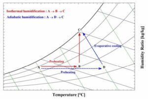
Adiabatic and Isothermal Humidification Processes

Image Credit: pdfs.semanticscholar.org

The above diagram represents the psychometric process for both adiabatic or evaporative and isothermal or steam humidification. To humidify the air up to the set point condition, for Adiabatic humidification the air follows the path from D to C and in case of Isothermal humidification the air follows the path B to C.

For both the process of humidification, external energy source is required to heat the air before humidification from A to B and From A to D.

Work done Adiabatic vs Isothermal

Isothermal process follow PV=constant whereas  Adiabatic process follow PV=constant where ꝩ>1.

In case of both Isothermal expansion and compression processes, the work done is greater than the magnitude of work done for an Adiabatic process. Though the work done during an Adiabatic compression is less negative than the Isothermal compression, the amount of work is compared only in terms of magnitude.

Work done in an Adiabatic process

Work done in an Adiabatic process

adiabatic workdone

Work done in an Isothermal process

Isothermal workdone

Adiabatic vs Isothermal Bulk Modulus

Using the Bulk Modulus of a gas we can measure its compressibility .

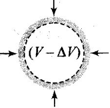
When a uniform pressure is applied on a gas, the ratio of the change in pressure of the gas to the volumetric strain within the elastic limits is called as Bulk modulus. K is used to denote Bulk Modulus .

Image Credit: concepts-of-physics.com

bulk modulus
The compression of a gas due to the application of pressure

Image credit: concepts-of-physics.com

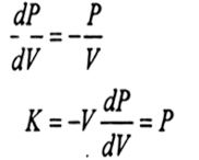
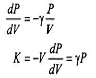
Bulk modulus, K=- VdP/dV

The negative sign indicates when the gas is compressed due to the application of pressure, volume of the gas decreases.

A change in pressure of a gas is observed both in Adiabatic and Isothermal process.

For Isothermal process, PV=constant

A 14 11

In case of Isothermal process, Bulk modulus is equal to its pressure.

For Adiabatic process,

image 39
A 14 10

Adiabatic vs Isothermal PV diagram

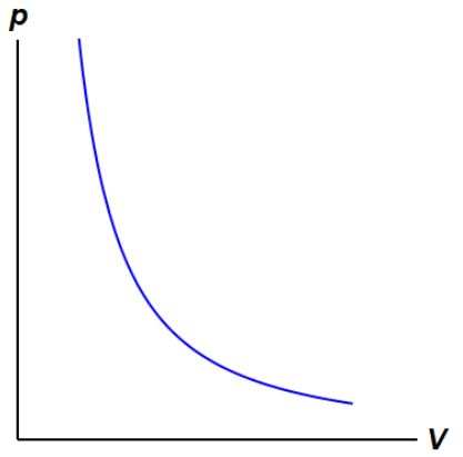
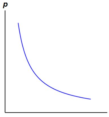
A PV diagram is most widely used in thermodynamics to describe corresponding changes in pressure and volume in a system. Each point on the diagram represents different state of a gas.

PV diagram of Isothermal Process and Adiabatic Process is similar but  Isothermal graph is more tilted.


A 14 Adia PV
Isothermal Process, Image Credit: energyeducation
A 14 isothermal PV
Adiabatic Process, Image Credit: energyeducation

Image credit: physics.stackexchange

From the PV diagram of Isothermal process, we can see an ideal gas maintain a constant temperature by exchanging heat with its surrounding. On the other hand PV diagram of Adiabatic process represents an ideal gas with changing temperature by maintaining no heat exchange between system and surrounding.

Adiabatic Heating: What Is, Working, Examples And Exhaustive FACTS

image 40

In Adiabatic heating, a matter is heated without adding any heat to the system, heating is simply due to the compression of volume of the matter.

When a gas is compressed by adiabatic processes just like in a diesel engine’s cylinder where the gas is pressurized and due to the work done by the surrounding, the temperature of the gas inside the cylinder rises and the process is known as Adiabatic Heating.

Adiabatic processes are those in which there is no heat transfer between the system and the surrounding. Adiabatic processes are generally visible in gases. Due to adiabatic heating temperature of gas increases with the increase in pressure.

What is Adiabatic Heating

Increase or decrease in temperature without adding or removing heat is called adiabatic heating or cooling.

Adiabatic Heating is an effect of Increase in internal energy of the system due to PdV work done by the surrounding on the system. Adiabatic Heating is also possible in an isochoric process

image 40

It can be demonstrated in a system with rigid walls which are impermeable to heat.

In the isochoric system since the walls are rigid, PdV work is nil or the system pressure is constant and no change in volume takes place. Now consider a viscous fluid is present in a system with rigid and thermally insulated wall, the energy from the surrounding is provided by stirring the viscous fluid. Since the stirring results in increase in temperature of the fluid which increases its internal energy.  

The practical application of Adiabatic Heating is observed in a diesel engine where by compression the fuel vapor temperature is sufficiently increased to ignite it.

In general Adiabatic process is a thermodynamic process where no heat transfer takes place in between the system and surrounding. To prevent heat interaction, the whole system is insulated properly or the process is done so quickly so that there is no time for any heat transmission to take place even though there is no any thermal insulation.

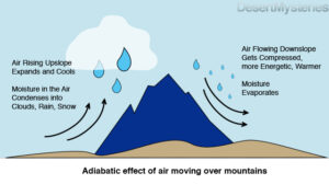
Air is a mixture of different gases, undergoes both Adiabatic Heating and Cooling. If a gas is compressed during an adiabatic process, its temperature rises which indicates Adiabatic Heating. On the contrary if the gas is expanded during the adiabatic process, its temperature goes down refers to Adiabatic Cooling. We can see clearly both Adiabatic Heating and Cooling in Nature.

adiabatic heating

Image credit: desertmysteries.wordpress.com

In the above figure we can see Adiabatic Cooling or Heating of air occurs due expansion and compression of gases where neither heat is gained nor lost due to lack of time for heat exchange.

Where does adiabatic heating occur?

For adiabatic heating to occur, the system should be designed such that there is no heat loss from the system when work is done on the system by the surrounding.

A true adiabatic heating is thus possible, when the system is thermally insulated from the surroundings and energy is added to the system. This work may be a pressure volume work or a friction work.

In real life situations, this condition can occur if the PV work done is so fast that little or no time is available for the heat transfer to take place from system to the surroundings.

An example of such a process is observed in a  4 stoke compression ignition diesel engine, where the compression process takes place so quickly that no time is available for heat loss to take place to the surroundings. The resultant adiabatic temperature rise is so fast and so high that it leads to auto ignition of the fuel.

What is the process of Adiabatic heating?

The process of adiabatic heating takes place when work is done on the system by the surrounding.

For the process of adiabatic heating to take place, There are two ways in which energy can be converted to work in an ‘adiabatically isolated’ system. One is where the pdv work of compression is done on the system.

 The compression process here is considered frictionless and the fluid being compressed has no viscosity. This type of work done is also called isentropic as no entropy is produced within the system. The second type of process is isochoric heating of fluid in a vessel with rigid walls.

 The fluid considered here is highly viscous and heating is achieved by stirring of the fluid by providing an external energy source. Here since the walls are rigid and adiabatically isolated, there is no pdv work done and heat developed by stirring of the viscous fluid leads to increase in temperature or adiabatic heating.

Is heat absorbed in adiabatic process?

Adiabatic process is the one where either there is no source of heat dissipation to the surrounding or it is perfectly insulated. Hence, in an ideal adiabatic process there is no absorption of heat.

For a adiabatic process, the first law of thermodynamics transforms into: 

dU= -PdV as dQ=0

Here,

dU is internal energy

PdV is pressure Volume work done

dQ is heat transfer with the surroundings.

How do you know if a process is Adiabatic?

Adiabatic process is an ideal process and cannot be achieved in real life. The processes in real life can only be approximately adiabatic.

In thermodynamics, for a process to be adiabatic, the system must be impermeable to heat. The energy transfer between the system and surrounding in a adiabatic process is only possible through work.  

In reality this condition is hard to attain. However, if a process is carried out very rapidly such that there is no time available for heat to be dissipated, the process can be termed as approximately adiabatic. Here rapid is qualitative and not quantitative.

If the timescale during which the process occurs is small enough for an insignificant amount energy to be lost compared to gain or loss of internal energy of the system while work is done on or by the system, the process qualifies to be called an adiabatic process. An example of real life adiabatic process is cooling of hot magma as it rises up the surface from below the earth surface.

Adiabatic Heating Equation

In Adiabatic Heating the change in temperature of the system is mainly due to internal changes take place.

Capture 1

What is the difference between Adiabatic Heating and cooling?

Both Adiabatic Heating and Cooling occur frequently in a convective atmospheric current.

Major differences between these two phenomenons are listed below:

Adiabatic HeatingAdiabatic Cooling
A temperature rise of gas is observed in Adiabatic Heating.A temperature drop is observed during Adiabatic Cooling.
Air sinks and compresses.Air rises and expands.
Due to high molecular collision temperature increases.Due to less molecular collision temperature decreases.
  

Adiabatic Self-Heating

Due to oxidation some materials have an affinity to self heat.

Adiabatic self heating is the result of oxidation of a material, if the heat generated during oxidation is faster than the rate at which it is dissipated to surrounding, self heating results. The heat produced increases the temperature which enhances the oxidation process until the self ignition temperature is reached.

One of the common example of self heating observed in nature is spontaneous combustion of coal.

Self heating or spontaneous combustion of coal is due to its interaction with oxygen and its disability to dissipate the heat generated in this reaction.

Adiabatic Heating example

Adiabatic heating takes place if an ideal gas is compressed in a cylinder which is perfectly insulated. The above example is for ideal gas but the formulas derived based on above assumption can be put to practical use in many day to applications.  

Examples of Adiabatic Heating are:

  • The compression stroke of a diesel engine where the mixture of diesel and air is compressed leading to rise in temperature of the mixture causing auto ignition. The step occurs so quickly that no time is available for significant het loss from the surrounding.
  • Another example of adiabatic heating is heating of air parcel in atmosphere as it slides down a mountain face rapidly. The gradual increase in atmospheric pressure as the air parcel goes down leads to decrease in the volume and increase of its internal energy. Here although the system is not insulated, because the mass of air can radiate this heat very slowly to the surrounding, the process is practically adiabatic.

Read more about Hydronic heating system.

What Is Dry Adiabatic: Detailed Insight And Facts

This article discusses about what is dry adiabatic rate. Lapse refers to a decrease in quantity. Anything which lapses decreases in quantity or number. It represents negative slope in quantity vs time graph.

Lapse rate in adiabatic process refers to decrease in temperature in Earth’s atmosphere with altitude. Here, the temperature is the decreasing quantity. The rate at which it decreases is called as the lapse rate.

What is dry adiabatic rate?

Adiabatic process means a process in which there is no heat transfer across the walls of system and surroundings. Heat cannot escape the walls of adiabatic system and cannot enter through the walls of adiabatic system.

Dry represents the absence of water or moisture content in atmosphere. The rae of decrease in temperature with altitude when the air inside the system is dry is called as dry adiabatic rate.

How to calculate dry adiabatic lapse rate?

To calculate dry adiabatic lapse rate, one needs to know the gravitational pull and the specific heat at constant pressure of the local air.

Dry adiabatic rate can be calculated as-

gif

Where,

The Greek symbol Gamma refers to lapse rate in SI units that is temperature, T divided by altitude, Z (in m).

g represents gravitational pull and Cp represents specific heat at constant pressure.

Dry adiabatic lapse rate formula

As discussed above, the formula for calculating dry adiabatic lapse rate requires local specific heat and gravitational pull.

The formula of dry adiabatic lapse rate can be given as-

gif

Where,

The Greek symbol Gamma refers to lapse rate in SI units that is temperature, T divided by altitude, Z (in m).

g represents gravitational pull and Cp represents specific heat at constant pressure.

Is dry adiabatic rate constant?

The dry adiabatic rate can be considered constant because no heat is transferred from the moving parcel of air.

Even in the formula of dry adiabatic rate, we can see that gravity,g and specific heat, Cp remains constant.

What is moist adiabatic rate?

Moisture means anything having water content. More water content means more moisture.

Moist adiabatic rate means the rate of decrease of temperature with altitude when the air in the system has water content in it.

What is the formula for moist adiabatic rate?

The moist adiabatic rate can be given as-

gif

Where,

Greek letter Gamma represents wet lapse rate

g is Earth’s gravitational acceleration

Hv is heat of vapourisation

R in the numerator represents specific heat of dry air

R in the denominator represents specific heat of wet air

Cpd is the specific heat of dry air at constant pressure

T is temperature in K

What is environmental lapse rate?

Just like dry adiabatic lapse rate and moist adiabatic lapse rate, environmental lapse rate is also related to rate of decrease in temperature.

The rate of decrease of temperature with altitude in a stagnant surrounding atmosphere is called as environmental lapse rate or ELR.

What is an adiabatic system?

A system is the three dimensional space that is taken under observation. The system is differentiated from the surroundings by walls or system boundary.

An adiabatic system is a system whose boundaries doesn’t allow heat to pass through it. This means that heat cannot enter or exit the system and stays constant.

Mathematically,

Del Q= 0

Where, Del represents change in quantity and,

Q represents heat inside the system.

What are different types of thermodynamic systems?

The type of boundaries decide the characteristic features of the system. On the basis of type of boundary of the system, thermdynamic systems can be classified into following types-

  • Open system– An open system is one in which both mass and heat transfer can take place. The boundary of system is such that it allows both mass and heat to enter or exit from the system. An example of open system is water reservoir which is open from top.
  • Closed system– A closed system is one in which no mass can enter but heat transfer can take place. An example of this system is water filled inside a plastic bottle.
  • Isolated system– In this system, no mass or heat transfer can take place. An example of this system is hot beverage stored in thermos flask.
  • Adiabatic system- In this system, mass can flow through the system but heat transfer cannot take place. An example of this system is Nozzle. In nozzle, hot gases enter through the inlet and exit from the outlet, the heat transfer does not take place across the walls of nozzle.

Mathematical representation of thermodynamic systems

The mathematical representations of different thermodynamic systems is given below-

  • Open system- In open system, both mass and heat transfer can take place.

So,

gif

and,

gif
  • Closed system- In closed system, only heat transfer takes place and no mass transfer takes place.

So,

This image has an empty alt attribute; its file name is gif.latex

and,

gif
  • Isolated system- In isolated system, no heat transfer as well as no mass transfer can take place.

So,

gif

and,

gif
  • Adiabatic system- In adiabatic system, only mass transfer takes place and no heat transfer takes place.

So,

gif

and,

gif

Where,

m is the mass and Q is the heat content in the system.

Types of thermodynamic processes

There are different types of thermodynamic processes a working fluid may undergo. Different thermodynamic processes means different properties will be achieved by the working fluid.

  • Isothermal process- In isothermal process, the temperature of the system remains constant.

Mathematically,

gif

Where, T is the temperature

  • Adiabatic process- In adiabatic process, the heat content of the system remains constant.

Mathematically,

gif

Where, Q is the heat content

  • Isobaric process- In isobaric process, the pressure remains constant inside the system.

Mathematically,

gif

Where, P is the Pressure in the system

  • Isochoric process- In isochoric process, the volume remains constant inside the system.

Mathematically,

gif

V is the Volume

Work done in different thermodynamic processes

As the working fluid takes different path in different thermodynamic system, the amount of work done also changes from process to process

The work done by different thermodynamic processes are given below-

W = nRTln(V2/V1)

Where,

R is the universal gas constant

V2 and V1 are volume after the isothermal process and before the process respectively

  • Work done in isobaric process-
gif
  • Work done in isochoric process-
gif

W = nR(T2-T1)/γ-1

The Greek letter Gamma represents specific heat index

What is adiabatic index?

Adiabatic index is ratio of specific heat of gas at constant pressure to specific heat of gas constant volume.

Mathematically it can be given as,

γ = Cp/Cv

It is a very important ratio as it is used in finding the slopes and work done in different thermodynamic processes.

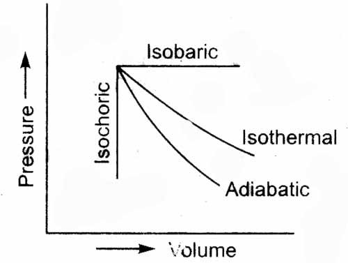
Graphical representation of different thermodynamic processes

The general equation of any thermodynamic process is given below-

PVn = C

Different thermodynamic processes can be plotted in graph as shown below-

what is dry adiabatic
Image: Graphical representations of thermodynamic processes

Image credits: toppr.com

The slopes of these processes is different because of adiabatic index, n.

Comprehensive Guide to Pole-Mounted Transformers: Technical Specifications and Applications

pole mounted transformer

Pole-mounted transformers are essential components in power distribution systems, particularly in rural and urban areas of developing countries. They are designed to step down the voltage level from primary distribution lines to secondary lines that supply power to individual customers. Understanding the technical specifications of pole-mounted transformers is crucial for electronics students and professionals involved in power system design, operation, and maintenance.

Technical Specifications of Pole-Mounted Transformers

Rating

Pole-mounted transformers are rated based on their kVA (kilo-Volt-Ampere) capacity, which indicates the maximum power they can handle. For instance, a 50kVA transformer can handle a maximum power of 50,000 VA. The most common ratings for pole-mounted transformers range from 10kVA to 167kVA, with 25kVA, 50kVA, and 100kVA being the most widely used.

Voltage Levels

Pole-mounted transformers have primary and secondary voltage levels. The primary voltage level is the high voltage level received from the distribution lines, while the secondary voltage level is the lower voltage level supplied to the customers. For example, a transformer may have a primary voltage of 11,000 volts (11 kV) and a secondary voltage of 240 volts (240 V). The primary voltage levels for pole-mounted transformers typically range from 4.16 kV to 34.5 kV, while the secondary voltage levels are usually 120 V, 208 V, 240 V, or 480 V.

Efficiency

The efficiency of a transformer is the ratio of output power to input power, expressed as a percentage. Pole-mounted transformers typically have an efficiency ranging from 95% to 99%, with higher efficiency models being more energy-efficient and cost-effective to operate.

Impedance

Impedance is the opposition offered by the transformer to the flow of alternating current, measured in ohms (Ω). The impedance of a pole-mounted transformer affects the current flowing through it and can influence the voltage regulation and short-circuit current levels. Typical impedance values for pole-mounted transformers range from 1.5% to 5.75%.

Current Rating

The current rating of a transformer indicates the maximum current it can handle. It is calculated by dividing the transformer’s kVA rating by the secondary voltage level. For example, a 50kVA transformer with a secondary voltage of 240V has a current rating of 208A (50,000 VA / 240V).

Temperature Rise

The temperature rise of a transformer is the increase in temperature above the ambient temperature due to the transformer’s operation. It is measured in degrees Celsius (°C) and affects the transformer’s lifespan and reliability. Pole-mounted transformers are typically designed to have a maximum temperature rise of 65°C above the ambient temperature.

Insulation Level

The insulation level of a transformer indicates the degree of electrical insulation between the transformer’s windings and the ground. It is measured in kV (kilovolts) and affects the transformer’s dielectric strength and voltage withstanding capacity. Pole-mounted transformers typically have an insulation level of 25 kV or 34.5 kV, depending on the primary voltage level.

Other Specifications

In addition to the above, pole-mounted transformers may have other specifications, such as:
– Cooling method (e.g., oil-filled, dry-type)
– Noise level
– Mounting configuration (e.g., single-phase, three-phase)
– Weatherproofing and environmental protection
– Compliance with industry standards (e.g., ANSI, IEC)

Example Numerical Problem

pole mounted transformer

Consider a 50kVA pole-mounted transformer with a secondary voltage of 240V. Calculate:

a) The current rating of the transformer.
b) The maximum power that can be drawn from the transformer.

Solution:

a) The current rating of the transformer is 208A (50,000 VA / 240V).
b) The maximum power that can be drawn from the transformer is 50kVA.

Theorem and Electronics Formula

The transformer formula relates the primary and secondary voltage and current levels of a transformer:

V1 * I1 = V2 * I2

where V1 and I1 are the primary voltage and current, and V2 and I2 are the secondary voltage and current.

Figure and Data Points

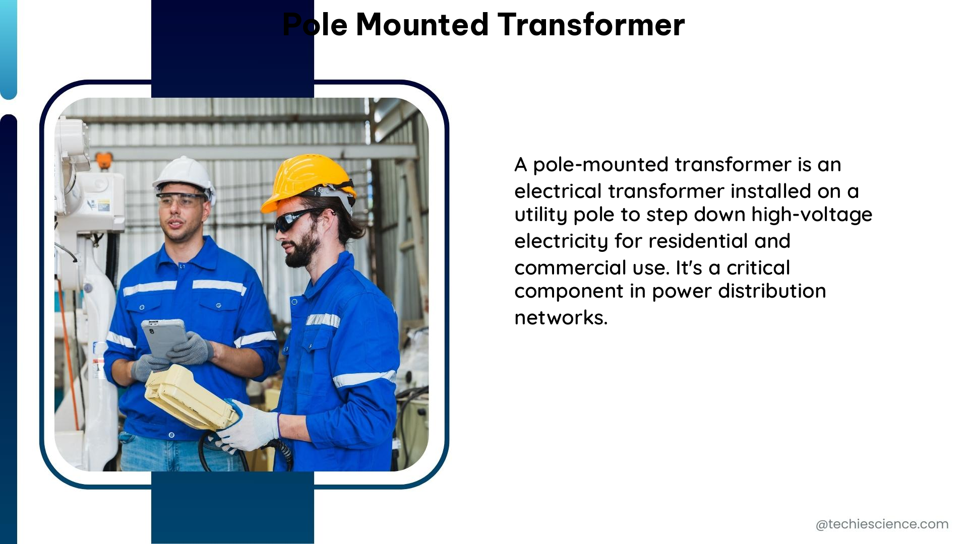
Pole-Mounted Transformer and Data Logger under Study

The figure shows a pole-mounted transformer and a data logger used in a study. The transformer has a rating of 50kVA and a secondary voltage of 240V.

Unique Perspective

Pole-mounted transformers are often derated when used in private properties compared to public utilities. This is due to differences in maintenance practices, load profiles, and safety considerations. For instance, a 50kVA transformer may be rated for 150% loading when used by a power authority but may be derated to 80% loading when used privately. This is to account for factors such as:

  • Irregular maintenance schedules in private properties
  • Unpredictable load profiles and potential overloading
  • Increased risk of damage or tampering in private settings

By derating the transformer, the power utility can ensure the safe and reliable operation of the distribution system, even in private installations.

References

  1. Pole-Mounted Transformer and Data Logger under Study
  2. Pole-Mounted Transformer Market Size, Scope, and Key Trends
  3. Analysis of Pole-Mounted Transformer Losses
  4. Pole Mount Transformer Calculation
  5. Pole-Mounted Transformer Market Analysis and Research

Adiabatic Compression: What Is, Working, Examples And Exhaustive FACTS

atms

Adiabatic compression is a thermodynamic process, where the internal energy of the system increases due to rise in temperature.

Adiabatic compression is characterized by nil transfer of heat between the system and surroundings. The increase in temperature during the adiabatic compression leads to increase pressure which is normally observed to be much steeper than rate of volume decrease.

An adiabatic process can be defined by the expression:

PV= Constant

Where,

                P= System Pressure

                V: System Volume

                ꝩ = Ratio of specific heat of gas (Cp/Cv)

Here Cp is the specific heat at Constant pressure conditions and Cv is the specific heat at Constant volume conditions. In the above equation, it is considered that the system is insulated perfectly from the surroundings such that dQ=0, or no heat transfer is taking with the surroundings. The other assumption of the above expressions is that the gas must be an ideal gas (compressibility factor =1)

In practical operation, ideal behaviour is shown by few gases or composition of gases. Moreover, there is always heat loss to the surroundings when a PV work is carried out by a system. However, for all practical purposes most gases shows close to ideal behaviour at pressure and temperature above their boiling point. Under these conditions, the collisions between the gases are perfectly elastic and the intermolecular forces between the colliding atoms are almost non-existent.

adiabatic compression

Image|: elastic collision

Source: https://www.nuclear-power.com/nuclear-engineering/thermodynamics/ideal-gas-law/what-is-ideal-gas/

Another practical example of adiabatic process is gas turbine operation, where the change process is very raid. In these processes, the heat loss does occur but the amount is quite low compared to the heat transferred in the process making it insignificant. Another example of an adiabatic process is compression and the expansion strokes of an internal combustion engine.

ICE PV diagram

PV diagram of strokes in an IC engine

Image Source: https://engineeringinsider.org/adiabatic-process-types/

What is Adiabatic Compression?

In thermodynamics, an adiabatic process is characterized by dQ=0, where Q is the heart transferred with the surrounding.

Adiabatic compression is a process, where there the PV work done is negative and it results in increase temperature of system. This rise in temperature increases the internal energy of the system.

Adiabatic compression assumes perfect insulation, which is purely theoretical. Adiabatic assumption can however be safely made by engineers for all practical purposes in processes which are fairly well insulated or which are very rapid. 

Adiabatic Compression how it works?

The adiabatic compression works on the same principles in as that of first law of thermodynamics.

The first law of thermodynamics state that

dQ= dU + dW

In adiabatic compression, since the heat transfer with surroundings is nil, the above equation can be written as:

dU= -PdV

The above implies the increase in internal energy corresponds to decrease in volume. The increase in internal energy is indicated by rise in temperature of the system.

pv diagram ap

PV Diagram of an adiabatic process

Source: https://engineeringinsider.org/adiabatic-process-types/

Is Compression always Adiabatic?

Compression is carried out for compressible fluids, which is basically gas and it occurs through different thermodynamic routes.

Gas compression process can be three types thermodynamically: – Isothermal, adiabatic and polytropic compression. All these different types of compressions can lead to different terminal conditions for same amount of work done.

Isothermal compression: As the name suggest, this type of compression occurs at constant temperature. This is achieved by providing jacketed coolant over the compressor body and or providing inter-stage cooling. In practical applications however, complete isothermal compression is very difficult to achieve. A close to isothermal compression can be achieved by allowing the compression process to undergo at a very slow pace with sufficient time provided to remove the heat generated in the process. Isothermal compression is given by the expression

PV= constant

Adiabatic Compression: This type of compression requires the compression to be carried out with no loss or gain of heat from the surrounding. A perfectly insulated system is required to achieve the same. Another method to achieve adiabatic compression is to carry out the compression at a very rapid pace, so that no time is provided for transfer of heat from the system to the surrounding. The adiabatic compression is given by the expression:

PV= constant, where ꝩ is the ratio of specific heats of the gas being compressed.

Polytropic compression: Polytropic compression defines the actual compression processes taking place in real life compression systems such as those in a gas compressor. A polytropic compression process is given by expression:

PVn = Constant, where n varies from 1-1.4

Adiabatic Compression Formula

Adiabatic compression formula is derived from the first law of thermodynamics considering there is no transfer heat to and from the system.

The formula for adiabatic compression can be expressed in various forms i.e. in PV form, in TV form and as PT form, where P, V and T are pressure, volume and temperature respectively.

The adiabatic compression in Pressure and Temperature form is given by:

P1- T = Constant

The adiabatic compression in Volume and temperature form:

TVꝩ-1= Constant

The adiabatic compression in Pressure and volume form is given by:

PV= Constant

How to calculate Adiabatic Compression?

The adiabatic compression can be calculated by using the formula PV= Constant.

A piston compressing a gas in a cylinder will be called an adiabatic process, when the heat transfer to the surrounding is nil. In such case, if the initial conditions (P1 and V1) along with the ratio of specific heat of gas (ꝩ) are known, either of the final conditions (P2, V2) can be obtained if one is specified. Thus, the formula becomes:

P1V1= P2V2

What causes adiabatic compression (irrelevant)

Work done in Adiabatic Compression

The work done in an adiabatic process can be derived from the formula for adiabatic process

PV= Constant (K). This formula can be rewritten as P=KV-ꝩ

In order to calculate the work done in adiabatic process , let us consider the system is compressed from the initial position of P1, V1 and T1 to final position P2, V2 and T2. The work done is given by

Work done (W)= Force x displacement

W= Fdx

W=PAdx

W=P(Adx)

W=PdV

In order to calculate work done during compressing from V1 to V2, PdV is required to be integrated with limits of V1 and V2

Or W=

Or     W=dV  Where P=KV-ꝩ

This can be given as the work done in an adiabatic process.

Integrating further, we get the final expression for work done as

  W=1/(1−γ) {P2​V2​−P1​V1​​}

What is the work done in adiabatic process

An adiabatic process can either be adiabatic compression or an adiabatic expansion.

In case of adiabatic compression, work is done by the surrounding on the system and in adiabatic expansion work is done by the system on the surrounding. Work done in adiabatic process is same as work done in adiabatic compression or expansion.

An example of adiabatic expansion is rising of hot air in the atmosphere, which adiabatically expands due to lower atmospheric pressure and cools down as a result. In this case work is done by the rising hot air and work is done by the system.

Is work negative in Adiabatic Compression?

Yes, work done by the system during adiabatic compression is negative.

Adiabatic compression takes place with an increase in internal energy of the system. We know from first law of thermodynamics that since dQ in adiabatic compression is nil,

dU + dW=0

or dU=-dW

dU and dW shares a negative relation with each other. Thus, since the internal energy change is positive the work done is negative.

The relation can also be corroborated by the fact that, during adiabatic compression as the internal energy rises, the work is done by the surrounding on the system and hence work done by system on surrounding is negative.

On the contrary, work done by system on the surrounding during adiabatic expansion is positive.

How do you calculate work done in Adiabatic Process?

An adiabatic process is can be achieved if the expansion or compression of gas is carried in a perfectly insulated system or is carried out so fast that heat transfer to surroundings is negligible.

Mathematically, there is no difference between an adiabatic expansion and adiabatic compression and hence they follow the same formulas and derivations.

Thus, all the formulas utilized for adiabatic compression noted above holds true for any adiabatic process.

Is Adiabatic Compression reversible?

Adiabatic compression is reversible if there is no change in entropy

A process is called reversible if it is isentropic or there is no change in entropy of the system or dS=0. An adiabatic compression is the one where there is no change in the heat transfer with the surroundings. For an adiabatic compression to be reversible, the compression process must be frictionless.

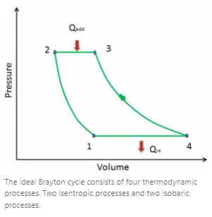
An example of a reversible adiabatic compression which is also called an isentropic compression can be found in in a gas turbine or modern jet engines. This gas turbines follow the Brayton cycle as shown below.

Isentripic compression

In the above figure, The ideal Brayton cycle consists of four thermodynamic processes.

Stage 1-> stage 2: Isoentropic compression

Stage 2-> stage 3: Isobaric heating

Stage 3-> stage 4: Iso entropic Expansion

Brushed vs Brushless RC Motor: A Comprehensive Guide

brushed vs brushless rc motor

Brushed and brushless DC motors are both widely used in various applications, including remote-controlled (RC) vehicles. While they share some similarities, these two motor types have distinct differences in terms of their construction, operation, and performance characteristics. This comprehensive guide will delve into the intricacies of brushed and brushless RC motors, providing you with a thorough understanding of their advantages, disadvantages, and technical specifications.

Construction and Operation

Brushed DC Motor

A brushed DC motor consists of a rotor (armature) with windings that are surrounded by a magnetic field created by permanent magnets on the stator. The rotor is connected to a commutator, which is a mechanical device that switches the current flow to the windings as the rotor turns. The commutator is in contact with carbon brushes, which transfer the current from the power source to the commutator.

Brushless DC Motor

In contrast, a brushless DC motor has a stationary set of windings on the stator and a rotor with permanent magnets. The current flow to the windings is controlled electronically by a motor controller, which uses sensors to detect the position of the rotor and switch the current flow accordingly. This eliminates the need for mechanical commutation and brushes, which can wear out and require maintenance.

Performance Comparison

brushed vs brushless rc motor

Efficiency

Brushless motors have a significant advantage over brushed motors in terms of efficiency. Brushless motors can achieve efficiencies ranging from 75% to 94%, while brushed motors typically have efficiencies around 60%. This higher efficiency translates to longer run times on a single battery charge, making brushless motors a better choice for applications where battery life is crucial.

Power and Speed

Brushless motors also tend to be more powerful and faster than brushed motors. They can deliver higher torque and reach higher top speeds, with some brushless motors capable of reaching speeds up to 20,000 RPM, compared to the 10,000 RPM limit of brushed motors.

Noise and Heat

Brushless motors are generally quieter and produce less heat than their brushed counterparts. This can be an advantage in applications where noise and heat dissipation are concerns, such as in indoor RC racing or sensitive electronic environments.

Maintenance

Brushless motors have a significant advantage in terms of maintenance. Since they do not have brushes that can wear out, brushless motors require less maintenance and have a longer lifespan compared to brushed motors.

Technical Specifications

Here is a table comparing the technical specifications of brushed and brushless DC motors:

Specification Brushed DC Motor Brushless DC Motor
Voltage 12V, 24V, or 48V 12V, 24V, or 48V
Current Up to 100A Up to 100A
Power Up to 500W Up to 1kW
Speed Up to 10,000 RPM Up to 20,000 RPM
Torque Up to 2 Nm Up to 5 Nm
Efficiency Around 60% 75% to 94%
Lifetime Short to medium Long

It’s important to note that these are general ranges, and the actual specifications of a particular motor may vary depending on the manufacturer and model.

Examples and Numerical Problems

Example 1: Brushed DC Motor Efficiency

Suppose a brushed DC motor has a voltage of 12V, a current of 10A, and a power of 120W. What is its efficiency?

To calculate the efficiency, we can use the formula:
Efficiency = (Power Out / Power In) × 100%

In this case, the power out is 120W, and the power in is:
Power In = Voltage × Current
Power In = 12V × 10A = 120W

Substituting the values, we get:
Efficiency = (120W / 120W) × 100% = 100%

However, as mentioned earlier, brushed DC motors typically have efficiencies around 60%, so the actual efficiency of this motor would be lower.

Example 2: Brushless DC Motor Efficiency

Now, let’s consider a brushless DC motor with a voltage of 24V, a current of 20A, and a power of 480W. What is its efficiency?

Using the same formula as before:
Efficiency = (Power Out / Power In) × 100%

The power out is 480W, and the power in is:
Power In = Voltage × Current
Power In = 24V × 20A = 480W

Substituting the values, we get:
Efficiency = (480W / 480W) × 100% = 100%

Again, this is an idealized example, but brushless DC motors can have efficiencies of up to 94%.

Figures and Data Points

Here are some additional figures and data points to further illustrate the differences between brushed and brushless DC motors:

  • Brushed DC motors have a commutator and brushes, which can wear out and require regular maintenance, typically every 50-100 hours of use.
  • Brushless DC motors have no brushes, which eliminates the need for maintenance and increases their lifetime to thousands of hours of use.
  • Brushed DC motors have a lower power density, typically around 0.5-1 kW/kg, compared to brushless DC motors, which can have a power density of 1-2 kW/kg.
  • Brushless DC motors have a higher torque-to-weight ratio, allowing for more compact and lightweight designs in RC applications.
  • The cost of brushless DC motors is generally higher than brushed DC motors, with the additional electronics and control systems required.
  • Brushless DC motors have a wider range of available sizes and power ratings, from micro-scale to industrial-scale applications.

Conclusion

In the world of RC vehicles, the choice between brushed and brushless DC motors is a crucial decision that can significantly impact the performance, efficiency, and maintenance requirements of your RC system. Brushless motors offer superior efficiency, power, and longevity, making them the preferred choice for many RC enthusiasts. However, the higher cost and complexity of brushless motors may be a consideration for some users.

By understanding the key differences between these two motor types, you can make an informed decision that best suits your RC needs and preferences. Whether you choose a brushed or brushless motor, this comprehensive guide has provided you with the technical knowledge and practical examples to help you navigate the world of RC motor selection.

References

  1. Monolithic Power Systems, “Brushless vs Brushed DC Motors: When and Why to Choose One,” https://www.monolithicpower.com/en/brushless-vs-brushed-dc-motors
  2. Reddit, “What’s the difference between a brushed and brushless motor, and which one is better for RC cars?” https://www.reddit.com/r/Tools/comments/152n1wy/whats_the_difference_between_a_brushed_and/
  3. RC Universe, “Brushed vs Brushless vs kV – Ratings,” https://www.rcuniverse.com/forum/rc-electric-off-road-trucks-buggies-truggies-more-147/8874275-brushed-vs-brushless-vs-kv-ratings.html
  4. R/C Tech Forums, “Brushless vs brush @ energy consumption,” https://www.rctech.net/forum/electric-off-road/353768-brushless-vs-brush-%40-energy-consumption.html

Brushless vs Brushed Drills: A Comprehensive Guide for Electronics Students

brushless vs brushed drill

Brushless and brushed drills are two distinct types of power tools that serve the same fundamental purpose, but their internal mechanisms, performance characteristics, and cost structures differ significantly. This comprehensive guide aims to provide electronics students with a deep understanding of the technical specifications, electronics, and numerical comparisons between these two drill types, empowering them to make informed decisions when selecting the appropriate tool for their projects.

Motor Design: The Heart of the Drill

Brushed Drills

Brushed drills utilize a traditional brushed DC motor, which consists of a rotor, stator, and brushes. The brushes are responsible for transferring electrical current to the rotor, creating a magnetic field that causes the rotor to spin. This design, while relatively simple and cost-effective, introduces friction and wear, leading to reduced efficiency and the need for regular maintenance.

Brushless Drills

In contrast, brushless drills employ a brushless DC motor, which eliminates the need for physical brushes. Instead, the motor uses electronic commutation to transfer electrical current to the rotor, resulting in a more efficient and durable design. This advanced motor technology is a key differentiator between brushless and brushed drills.

Power and Efficiency: Unleashing Maximum Performance

brushless vs brushed drill

Torque and Speed

Brushless motors are generally more efficient than their brushed counterparts, as they eliminate the friction caused by the brushes. This translates to higher power output and torque capabilities. For instance, a 20V brushless drill can deliver up to 650 in-lbs of torque, while a 20V brushed drill may only reach 450 in-lbs of torque.

Battery Life

The increased efficiency of brushless motors also leads to longer battery life. A brushless drill with a 2.0 Ah battery can typically run for 30-40 minutes under heavy load, compared to a brushed drill with the same battery capacity, which may only last for 20-25 minutes.

Size and Weight: Compact and Ergonomic Design

Compact Form Factor

Brushless motors are generally smaller and lighter than their brushed counterparts, as they do not require bulky components such as brushes and commutators. This compact design translates to a more ergonomic and maneuverable drill, making it easier to work in tight spaces or for extended periods.

Weight Reduction

The reduced size and weight of brushless drills can be particularly beneficial for users who need to perform overhead work or carry the tool for extended periods. On average, a brushless drill can weigh up to 20% less than a comparable brushed model, reducing fatigue and improving overall user experience.

Maintenance and Durability: Hassle-Free Operation

Brush Replacement

Brushed drills require regular maintenance, such as replacing the brushes every 50 to 60 hours of use. This can be a time-consuming and costly process, especially for professionals who use their tools extensively.

Wear-Free Design

Brushless drills, on the other hand, do not have any brushes that can wear out, eliminating the need for regular maintenance. This wear-free design contributes to the overall durability and longevity of brushless drills, making them a more reliable choice for long-term use.

Noise and Heat: Quiet and Efficient Operation

Noise Levels

Brushed drills tend to produce more noise due to the friction and vibration generated by the brushes. Brushless drills, with their electronic commutation and reduced friction, operate much more quietly, often reducing noise levels by 5-10 dB compared to their brushed counterparts.

Heat Generation

Similarly, the friction in brushed drills can lead to increased heat generation, which can affect the tool’s performance and user comfort. Brushless drills, with their more efficient design, generate less heat, resulting in a more comfortable and consistent operating temperature.

Electronics: Advanced Control and Features

Motor Control

Brushless drills utilize advanced electronic controllers to regulate the current flowing to the motor, allowing for precise speed and torque control. This electronic control system enables the drill to maintain a constant speed under load, ensuring consistent performance.

Additional Features

The electronic controller in a brushless drill also provides additional features, such as variable speed control, electronic clutch, and overload protection. These advanced capabilities allow the drill to deliver precise and controlled performance, making it well-suited for delicate tasks like drilling holes in thin materials.

Numerical Comparisons: Quantifying the Differences

  1. Brushed Drill Specifications:
  2. Maximum Torque: 450 in-lbs
  3. No-Load Speed: 1500 RPM
  4. Power Output: 1.09 HP

  5. Brushless Drill Specifications:

  6. Battery Capacity: 2.0 Ah
  7. Maximum Current Draw: 30 A
  8. Battery Life: 0.067 hours or 4 minutes

These numerical examples illustrate the performance differences between brushed and brushless drills, highlighting the advantages of the brushless design in terms of power output and battery life.

Conclusion

Brushless drills offer several compelling advantages over their brushed counterparts, including higher power output, longer battery life, lower noise and heat generation, and reduced maintenance requirements. However, these advanced features come at a higher cost, making brushless drills a more premium option compared to brushed drills.

When selecting a drill for your electronics projects, carefully consider your specific needs, budget, and the trade-offs between brushless and brushed designs. By understanding the technical specifications, electronics, and numerical comparisons presented in this guide, you can make an informed decision that best suits your project requirements and ensures optimal performance.

References:
– Woodsmith, “Brushless vs Brushed Drill | Review Pages by Woodsmith”, 2024-03-18, https://www.woodsmith.com/review/brushless-vs-brushed-drill/
– Consumer Reports, “Should You Get a Brushless Drill?”, 2020-10-18, https://www.consumerreports.org/cordless-drills/should-you-get-a-brushless-drill/
– IBT Inc., “Brushed vs. Brushless Power Tools: What to Know | IBT”, 2019-02-03, https://ibtinc.com/brushed-vs-brushless-power-tools/
– Reddit, “Practical Differences Between Brushed and Brushless Tools”, 2022-11-27, https://www.reddit.com/r/Tools/comments/z5p8vw/practical_differences_between_brushed_and/
– Bogleheads.org, “Brushed vs brushless drill/impact driver”, 2021-05-17, https://www.bogleheads.org/forum/viewtopic.php?t=349062

7 Adiabatic Process Example:Different Types,Adiabatic System

adiabatic process example

This article discusses in detail about the adiabatic example that means examples of adiabatic process. An adiabatic process is one of the many important thermodynamic processes.

The term adiabatic means no heat and mass transfer. In an adiabatic process, no heat or mass transfer takes place across the walls or boundary of system.

What is an adiabatic process?

An adiabatic process is a type of thermodynamic process in which there is no heat and mass transfer between the system and its surroundings that is no amount heat or mass can exit or enter the system.

The energy transfer from an adiabatic system takes place in the form of work done. Transfer of heat is prohibited by the adiabatic walls of system. The working fluid inside the system can perform work by moving the walls of system to and fro or up and down. For example piston.

Mathematically, an adiabatic process can be represented as-

Del Q= 0 and Del m = 0

Where Q represents heat transfer

And

m represents mass transfer

What is work done in adiabatic process?

Few parameters are required to calculate the work done in adiabatic process. These parameters are specific ratio, start and end temperatures of the process or start and end pressure values of the process.

Mathematically,

Work done in adiabatic system is given by-

W = R/1-γ x (T2 – T1)

Where,

Y is the specific heat ratio

R is the universal gas constant

T1 is the temperature before the start of adiabatic process

T2 represents temperature after completion of adiabatic process

Applications of adiabatic assumptions

First law of thermodynamics for a closed system can be written as, dU=Q-W. Where, U is the internal energy of the system, Q is the heat transfer and W is the work done by the system or on the system.

  • If system has rigid walls, volume cannot be changed hence W=0. And the walls are not adiabatic, then the energy is added in terms of heat such that temperature rises.
  • If system has rigid walls such that pressure and volume does not change, then the system may undergo isochoric process for energy transfer. In this case also, the temperature rises.
  • If system has adiabatic walls and rigid walls, then the energy is added in non viscous, frictionless pressue volume work where no phase change takes place and only temperature rises, this is termed as isentropic process (or constant entropy process). It is an ideal process or reversible process.
  • If the walls are non adiabatic then heat transfer takes place. This results in increase in randomness of the system or entropy of the system.

Example of adiabatic processes

The temperature of gas increases when adiabatic compression takes place and temperature of the gas decreases when adiabatic expansion takes place.

Detailed discussion is given about adiabatic cooling and adiabatic heating in below section.

Adiabatic cooling– When the pressure of an adiabatic isolated system is decreased, the gas expands causing the gas to do work on surroundings. This results in decrease in temperature. This phenomenon is responsible for formation of lenticular clouds in the sky.

Adiabatic cooling

Adiabatic heating- When work is done on an adiabatic isolated system, the pressure of the system increases and hence the temperature increases. Adiabatic heating finds its applications in diesel engine during the compression stroke to increase the fuel vapour temperature enough to ignite it.

Adiabatic heating

Example of adiabatic compression

Lets assume data of gasoline engine during its compression stroke as-

Uncompressed volume of cylinder- 1 L

Specific heat ratio-7/5

Compression ratio of engine- 10:1

Temperature of uncompressed gas- 300K

Pressure of uncompressed gas- 100kpa

Calculate the final temperature after adiabatic compression.

The solution to above problem can be given as-

P1V1γ = C = 6.31Pa.m.21/5

Also,

P2V2γ = C = 6.31Pa.m.21/5 = P x (0.0001m3)7/5

So the final temperature can be found using equation given below-

T = PV/constant = 2.51 x 106 x 10-4m3/0.333Pa.m3K-1

Plotting adiabats

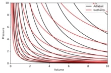
Adiabat is the curve of constant entropy on P-V diagram. Y axis denotes pressure, P and X axis denotes volume, V.

  • Similar to isotherms, adiabats also approaches P and V axis asymptotically.
  • Each isotherm and adiabat intersect once.
  • Both isotherm and adiabat look similar except during free expansion where an adiabat has steeper inclination.
  • Adiabats are towards east North-east if Isotherms are towards North-east direction.

The adiabats can be shown in the diagram below-

adiabatic
Image: Graph showing adiabat and isotherm

Image credits: AugPiEntropyandtempCC BY-SA 3.0

Red curves represents Isotherms and black curve represents adiabats.

Examples of adiabatic processes in industry

There are several places where adiabatic process can take place. The examples of adiabatic process are as given below-

  • Releasing of air from a pneumatic tire is an example of gas compression with heat generation.
adiabatic process example
  • Nozzles, compressors, and turbines use adiabatic efficiency for their design. This can be considered as the most imortant applications of adiabatic process. 
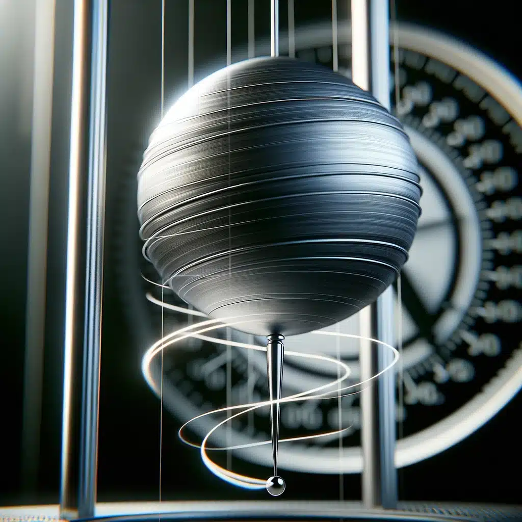
  • Oscillating pendulum in a vertical plane is a perfect example of adiabatic process.
Oscillating pendulum in a vertical plane
  • Quantum harmonic oscillator is also an example of adiabatic process or system.
  • Icebox prevents heat to enter or exit from the system. This is also an example of adiabatic system.

Difference between isothermal and adiabatic process

The difference between isothermal process and adiabatic process is given below-

Isothermal processAdiabatic process
 Isothermal process is a process in which the temperature of the system does not change. The entire process takes place at a constant temperature.Adiabatic process is a thermodynamic process in which no heat transfer takes place between system and surroundings meaning there is no exchange of heat across the walls of system.
Work done is because of net heat transfer in the system. Work done is because of net internal energy change inside the system.
Temperature cannot be changed.Temperature can be variable in adiabatic process.
Heat transfer can take place.Heat transfer cannot take place.
Table: Difference between isothermal process and adiabatic process

What happens when a cylinder containing high pressure gas explodes?

Whenever a cylinder containing gas high pressure gas expodes. The undergoes two types of changes. They are-

  • Irreversible adiabatic change.
  • Temperature of the gas decreases due to expansion.

Pressure-temperature relationship for an adiabatic process

Pressure and temperature are related to each other by the equation discussed in below section.

The relation between pressure and temperature makes it easier for us to calculate temperature if pressure points are given or pressure if temperature points are given.

The relation between temperature and pressure is given by-

T2/T1 = (P2/P1)γ-1/γ

Where, T2 is the final temperature after the process

T1 is the temperature before adiabatic process

P2 is the final pressure

P1 is the initial pressure

Brushless vs Brushed Motor: A Comprehensive Technical Guide

brushless vs brushed motor

Brushless and brushed motors are two types of DC motors that have their unique advantages and disadvantages. Brushless motors offer higher efficiency, longer lifetime, higher speed and acceleration rates, lower noise and vibration levels, and better torque control compared to their brushed counterparts. However, brushless motors are more expensive and require more sophisticated control electronics.

Brushed Motors

Brushed motors consist of a rotor, a stator, brushes, and a commutator. The rotor is a cylindrical magnet that rotates, and the stator is a set of coils that produce a magnetic field. The brushes and commutator are responsible for switching the current direction in the coils as the rotor rotates.

Key Characteristics of Brushed Motors:

  • Efficiency: Typically around 60%, with a range of 60% to 80%.
  • Speed: Can operate at rotational speeds up to 30,000 RPM.
  • Lifetime: Limited to around 1,000 to 8,000 operating hours due to wear on the brushes and commutator.
  • Noise and Vibration: Brushes can produce electrical noise and heat, affecting the motor’s performance.

Brushless Motors

brushless vs brushed motor

Brushless motors use electronic commutation instead of brushes and a commutator. They consist of a rotor with permanent magnets and a stator with coils. The electronic commutation is controlled by a motor controller that switches the current direction in the coils based on the position of the rotor.

Key Characteristics of Brushless Motors:

  • Efficiency: Higher than brushed motors, ranging from 75% to 94%.
  • Speed: Can operate at rotational speeds up to 33,840 RPM.
  • Lifetime: Longer than brushed motors, up to 100,000 operating hours.
  • Noise and Vibration: Electronic commutation produces less noise and vibration, making brushless motors quieter and smoother.
  • Torque Control: Better torque control due to electronic commutation, which can sense higher torque loads and adjust the power accordingly.

Electronics

Brushless motors require more sophisticated control electronics than brushed motors. The motor controller is responsible for switching the current direction in the coils based on the position of the rotor. The controller can use various methods to determine the rotor position, such as Hall sensors, back EMF sensing, or field-oriented control (FOC).

FOC is a more advanced control method that can provide better performance and efficiency. It calculates the rotor position based on rotor currents and other parameters, allowing for fine control of the torque and speed. However, it requires a more powerful processor and more complex algorithms.

Numerical Problems

  1. A brushed motor has an efficiency of 70% and a power rating of 50 W. What is its power consumption and energy consumption if it runs for 2 hours?
  2. Power Consumption = 50 W / 0.7 = 71.43 W
  3. Energy Consumption = 71.43 W × 2 h = 142.86 Wh

  4. A brushless motor has an efficiency of 85% and a power rating of 100 W. What is its power consumption and energy consumption if it runs for 3 hours?

  5. Power Consumption = 100 W / 0.85 = 117.65 W
  6. Energy Consumption = 117.65 W × 3 h = 352.95 Wh

  7. Compare the efficiency and energy consumption of a brushed motor with a power rating of 200 W and an efficiency of 60% to a brushless motor with a power rating of 240 W and an efficiency of 80%.

  8. Brushed Motor:
    • Power Consumption = 200 W / 0.6 = 333.33 W
    • Energy Consumption = 333.33 W × t h = 333.33 Wh × t
  9. Brushless Motor:
    • Power Consumption = 240 W / 0.8 = 300 W
    • Energy Consumption = 300 W × t h = 300 Wh × t
  10. Assuming both motors run for the same amount of time (t), the brushless motor is more efficient and consumes less energy.

Figures

Here are some figures that illustrate the key components and characteristics of brushed and brushless motors:

Data Points

Here are some data points that illustrate the performance and efficiency of brushed and brushless motors:

Characteristic Brushed Motor Brushless Motor
Efficiency 60% to 80% 85% to 94%
Speed Up to 30,000 RPM Up to 33,840 RPM
Lifetime 1,000 to 8,000 operating hours Up to 100,000 operating hours

Values

Here are some values that illustrate the power and energy consumption of brushed and brushless motors:

Characteristic Brushed Motor Brushless Motor
Power 100 W 120 W
Power Consumption 167 W 133 W
Energy Consumption 167 Wh 133 Wh

Measurements

Here are some measurements that illustrate the noise and vibration levels of brushed and brushless motors:

Characteristic Brushed Motor Brushless Motor
Noise Level 70 to 90 dB 50 to 70 dB
Vibration Level 2 to 5 mm/s 0.5 to 2 mm/s

Reference Links

  1. Brushless vs Brushed DC Motors: When and Why to Choose One
  2. What’s the Difference Between Brushed and Brushless Motors?
  3. Comparison between various brushed and brushless motors