Does the Quality Factor Q Affect the Transition Region of a High-Pass Filter?

does the quality factor q affect the transition region of an hpf

The quality factor (Q-factor) is a crucial parameter that significantly impacts the performance and characteristics of high-pass filters (HPFs). In the context of HPFs, the Q-factor directly affects the transition region, which is the area between the passband and the stopband where the filter transitions from allowing signals to pass through to blocking them. Understanding … Read more

Bending Strength Of Steel: Several Use Cases And Examples

I channel 300x256 1

This article discusses about bending strength of steel. Bending strength is the ability of a material to resist or withstand the bending stress applied.

Strength is ability to withstand or resist a particular amount of stress. A material has a particular amount of strength, only that much stress it can withstand. Any amount of stress which exceeds the strength can lead to material failure. Simply put, the applied stress should be lesser than the strength of the material for minimizing failure.

What is bending strength?

Bending strength or flexural rigidity is the ability of a work piece to withstand bending stress. The flexural strength depends on the failure load, effective length of the work piece and the dimensions of the cross section of the beam.

Mathematically the bending strength is given as-

σb = M.y/I

where,

sigma is bending strength or maximum allowable bending stress that can be applied before fracture

M is the bending moment

I is the moment of inertia of the cross section of the work piece

What is bending stiffness?

Bending stiffness and bending strength are not same. As discussed above, bending strength is the ability of the work piece to withstand a given amount of bending stress.

On the other hand, bending stiffness tells the amount of deflection the work piece will undergo under a given amount of bending stress. The bending stiffness depends on moment of inertia of cross section the work piece and the modulus of rigidity of the material of work piece.

Mathematically, bending stiffness can be given as-

Bending stiffness = E x I

Where, E is the Young’s modulus or modulus of rigidity

I is the moment of inertia of the cross section of the work piece

Bending strength of stainless steel

The bending strength not only depends on the material but the dimensions of the work piece too. The table below shows the bending strength of a stainless steel bar.

Base metal Bending strength (MPa)
700 W 267
700 F 817
900 W 750
900 F 633
Table: Bending strength of welded stainless steel pipes
Data Source: Investigation on Mechanical Properties of Austenitic Stainless-Steel Pipes Welded by TIG Method – Scientific Figure on ResearchGate. Available from: https://www.researchgate.net/figure/Mechanical-properties-of-the-base-steel-and-four-steel-welded-pipes_tbl1_329360548 [accessed 22 Jan, 2022]

Bending strength of steel pipe

Steel pipes are used at a large scale in industries. It is very important to know the physical properties of steel pipe and the behaviour of these pipes under different types of loads.

Bending strength of steel pipe can be found using the formula given below-

σ = 32MD/π(D4-d4)

where,

D is the outer diameter of pipe

d is the inner diameter of pipe

Pipe is simply a hollow cylinder.

Bending strength of steel plate

Let us assume a steel plate having a depth d and breadth b. The permissible load acting it is P.

The bending strength of this steel plate is given by following-

σ = 3M/bd2

Plate has a rectangular cross section where,

b is the breadth

d is the depth of rectangle

M is the bending moment

Bending strength of steel rod

Steel rods are widely used in construction industry for reinforcement purpose. They are used in aircrafts as well. To avoid construction failure, it is very important to know the mechanical properties of rods being used.

Let us consider a steel rod of diameter d. The bending strength can be given by the following formula-

σ = 32M/πd3

Bending strength of steel bar

Let us assume a circular steel bar of diameter d having permissible force value P. Then the bending strength formula for steel bar will be same as that of steel rod.

The bending strength of steel rod is discussed in above sections.

Bending strength of steel channel

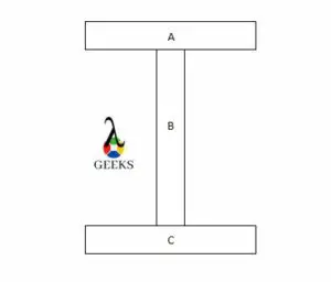
Let us consider a “I” steel channel as shown in the figure below.

Bending strength of steel
Image: Cross section of I channel

To find the moment of inertia of the entire cross section, we add the individual moment of inertia of the parts A, B and C.

The bending strength of this channel can be written from the basic formula. That is,

σb =M.y/I

Bending strength of steel square tube

Square tube is simply a hollow square cross section tube. These tubes are used in construction industry and interior designing. It is very important to know the bending strength of square tube before taking into use.

The section modulus of a square tube can be given by-

σ = bd3/3

Hence the bending strength becomes,

σ = 3M/ bd3

How to calculate bending strength of steel

Bending strength can be found using flexural test. Flexural tests can be performed with a single axial load, three point loading set up and four point loading set up.

Let us consider a three point set up. The given data for the set up is given below-

The work piece is a rectangular bar having breadth of 10cm and depth of 10 cm. The length of the bar is 1m and the load at failure is 10kN.

To find the bending strength of in a three point flexural test, following formula is used-

σ = 3FL/ 2bd2

Substituting all the values in above formula we have,

Bending strength= 15 MPa

How to calculate yield strength of steel

Yield strength of any material can be found using a tensile test on universal testing machine. The machine pulls the work piece from its ends and provides us with a stress strain graph from which we can easily make out the tensile strength of the material.

Let us consider the given data-

Load at failure- 5kN

Area of cross section- 1mm^2

The yield strength can be calculated using the formula-

Syt = P/A

Substituting the values in above equation we get,

Yield strength= 500Mpa

The diagram obtained from this test is commonly called as stress strain diagram.

Stress strain diagram

The graph which shows relationship between stress and strain is called as stress strain diagram.

This graph gives information like yield point, proportional limit, fracture point and ultimate tensile strength of the specimen. This diagram makes it easy to measure the mechanical properties of the specimen.

Mastering the Art of Finding Parallel Resistance: A Comprehensive Guide

how to find parallel resistance

In the world of electrical circuits, understanding the concept of parallel resistance is crucial for designing, analyzing, and troubleshooting various electronic systems. This comprehensive guide will delve into the intricacies of finding parallel resistance, providing you with a step-by-step approach and a wealth of technical details to ensure you become a proficient practitioner in this field.

Understanding Parallel Resistance

Parallel resistance is a fundamental concept in electrical engineering, where multiple resistors are connected in a parallel configuration. In a parallel circuit, the current has multiple paths to flow through, and the total resistance of the circuit is always less than the resistance of the individual components.

The formula to calculate the equivalent resistance (Req) of a parallel circuit is:

1/Req = 1/R1 + 1/R2 + 1/R3 + … + 1/Rn

Where R1, R2, R3, …, Rn are the individual resistor values in the parallel circuit.

Calculating Parallel Resistance: Step-by-Step Approach

how to find parallel resistance

To find the parallel resistance of a circuit, follow these steps:

Step 1: Identify the Resistors in Parallel

The first step is to identify the resistors that are connected in parallel. This can be done by carefully examining the circuit diagram or the physical layout of the components.

Step 2: Determine the Individual Resistor Values

Once you have identified the resistors in parallel, you need to determine the individual resistance values. This information can be obtained from the circuit diagram, component datasheets, or by directly measuring the resistors using a multimeter.

Step 3: Apply the Parallel Resistance Formula

With the individual resistor values, you can now apply the parallel resistance formula to calculate the equivalent resistance of the circuit:

1/Req = 1/R1 + 1/R2 + 1/R3 + … + 1/Rn

Step 4: Simplify the Calculation

After applying the formula, you may need to simplify the calculation to arrive at the final equivalent resistance value. This may involve performing mathematical operations such as addition, subtraction, multiplication, and division.

Step 5: Verify the Result

Once you have calculated the equivalent resistance, it’s important to verify the result. You can do this by checking the calculated value against the expected or measured resistance of the circuit.

Examples and Case Studies

Let’s explore some practical examples to solidify your understanding of finding parallel resistance.

Example 1: Two Resistors in Parallel

Suppose you have two resistors, R1 = 20 Ω and R2 = 30 Ω, connected in parallel. To find the equivalent resistance, we can use the formula:

1/Req = 1/R1 + 1/R2
1/Req = 1/20 + 1/30
1/Req = 3/60 + 2/60
1/Req = 5/60
Req = 60/5 Ω
Req = 12 Ω

Therefore, the equivalent resistance of the parallel circuit with two resistors is 12 Ω.

Example 2: Three Resistors in Parallel

Now, let’s consider a parallel circuit with three resistors: R1 = 20 Ω, R2 = 30 Ω, and R3 = 30 Ω. To find the equivalent resistance, we can use the formula:

1/Req = 1/R1 + 1/R2 + 1/R3
1/Req = 1/20 + 1/30 + 1/30
1/Req = 3/60 + 2/60 + 2/60
1/Req = 7/60
Req = 60/7 Ω
Req ≈ 8.57 Ω

Therefore, the equivalent resistance of the parallel circuit with three resistors is approximately 8.57 Ω.

Example 3: Parallel Resistance with Varying Resistor Values

In this example, let’s consider a parallel circuit with four resistors: R1 = 10 Ω, R2 = 20 Ω, R3 = 30 Ω, and R4 = 40 Ω. To find the equivalent resistance, we can use the formula:

1/Req = 1/R1 + 1/R2 + 1/R3 + 1/R4
1/Req = 1/10 + 1/20 + 1/30 + 1/40
1/Req = 4/60 + 3/60 + 2/60 + 1.5/60
1/Req = 10.5/60
Req = 60/10.5 Ω
Req ≈ 5.71 Ω

Therefore, the equivalent resistance of the parallel circuit with four resistors of varying values is approximately 5.71 Ω.

Practical Applications and Considerations

Parallel resistance is widely used in various electronic circuits and systems, including:

  1. Power Supply Circuits: Parallel resistors are often used in power supply circuits to distribute the current load and ensure efficient power distribution.
  2. Sensor Networks: In sensor networks, parallel resistors are used to create voltage divider circuits for signal conditioning and processing.
  3. Lighting Systems: Parallel resistors are employed in lighting systems, such as LED arrays, to ensure uniform current distribution and prevent individual LEDs from burning out.
  4. Analog Circuits: Parallel resistors are used in analog circuits, such as amplifiers and filters, to provide feedback, load balancing, and impedance matching.
  5. Digital Circuits: Parallel resistors are used in digital circuits, such as pull-up or pull-down resistors, to ensure proper logic levels and prevent signal degradation.

When working with parallel resistance, it’s important to consider the following factors:

  1. Power Dissipation: In a parallel circuit, the power dissipated by each resistor is inversely proportional to its resistance value. Ensure that the resistors can handle the power dissipation without exceeding their rated limits.
  2. Tolerance and Accuracy: The tolerance and accuracy of the individual resistors can affect the overall equivalent resistance. Consider using resistors with tight tolerance specifications for critical applications.
  3. Temperature Effects: Resistor values can change with temperature, which can impact the equivalent resistance of the parallel circuit. Account for temperature variations in your design and analysis.
  4. Parallel Resistance in Series Circuits: When dealing with a combination of series and parallel circuits, the equivalent resistance of the parallel portion must be calculated first before determining the overall series resistance.

Conclusion

Mastering the art of finding parallel resistance is a crucial skill for any electronics engineer or technician. By following the step-by-step approach and understanding the underlying principles, you can confidently tackle a wide range of parallel resistance problems, from simple two-resistor circuits to more complex multi-resistor configurations.

Remember, the key to success in this field lies in your ability to apply the parallel resistance formula, simplify the calculations, and verify the results. With the examples and practical considerations provided in this guide, you are well on your way to becoming a proficient practitioner in the world of parallel resistance analysis.

Reference:

  1. Resistors in Parallel: Circuit Analysis with Parallel Resistance
  2. How to Calculate Series and Parallel Resistance
  3. Resistors in Parallel

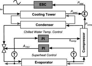
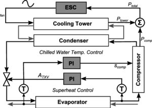
Low Discharge Superheat: Process, Formula, Work, Example And Exhaustive FACTS

Chiller inner loop controls of superheat and chilled water temperature 3 300x214 1

In this article we will discuss about the “Low discharge superheat” and its related factors.

The Low discharge superheat is when the refrigerant liquid flooding to the compressor or in the screw compressor in the very low oil temperature. The insufficient amount of air flows through the evaporator coils causes low discharge superheat.

With a high ambient temperature the refrigerant liquid go back to the compressor which causes the leakage to the heat exchangers and liquid injection device if it is fitted. This condition also point to an Actuator or Check valve issue. A dirty air filter, evaporator coil or air flow causes discharge measure low. The heat which is carried by the coils is low which result in low discharge superheat.

Process:

The low discharge superheat can be obtaind by the following,

  • At first we need to run the refrigeration system minimum for 10 min.
  • When the system running for a while we have to attach the pipe clamp thermocouple in one side of the refrigerant line which actually separate the thermal expansion valve and the condenser discharge valve.
  • Connect with the refrigerant manifold gauges with discharge service valve.
  • Read refrigerant manifold gauge to check the discharge service valve.
  • Check the thermocouple temperature using a digital thermometer.
  • Measure the pressure chart and temperature for the refrigerant.
  • Now need to turn over the condenser pressure reading to a condenser saturation temp.
  • Pressure takes from the thermocouple and the temperature of the condenser saturation from it.

Formula:

The low discharge superheat is calculated in the way as any other discharge superheat calculated on a system, by measuring the low discharge superheat and have to subtract the suction superheat and then then leaves with a figure of how much low superheat the compressor has given through compression and mechanical/electrical inefficiencies.

Work:

Prevent damage the machine from worn rings, acid formation and oils breakdowns and make it run more effective.

Example:

Let, the Discharge Temperature = 152, Condensing Sat. Temp. = 91

Then the discharge superheat would be = 61

Exhaustive facts:

In the discharge superheat refrigerant is saturated with oil causes low discharge superheat. Low discharge superheat can causes low temperature to the compressor, if the condition goes more low and low then it could damage the compressor too.

What does a low superheat indicate?

The low discharge of a system means refrigerant liquid floods to the compressor for the load is present through the evaporator coil.

When excess amount of refrigerant is enter into the coil or excessive amount of heat present into coil to vaporize the refrigerant properly,that time this condition appear.

Read more about Low Superheat: Important Terms and 3 FAQs

What causes low discharge superheat?

  • Flooding to the compressor with the refrigerant liquid through the evaporator coil. The situation mostly happened when the expansion valve overfeeding to the evaporator or faulty of an actuator.
  • Pressure is too high.
  • Low evaporator air flow.
  • Temperature is low.
  • The shape of the system is over sized during discharge of a superheated liquid.
  • Reduced airflow through the evaporator.
  • Due to low cooling water flow or dirty tubes the refrigerant charge may be excess.
  • Over charged of refrigerant liquid or oil.

Low discharge superheat trane chiller:

With the help of the compressor’s discharge temperature the inside condition of the refrigeration or air conditioning system easily can be recognize. In other term the discharge temperature describe as a measurement of the superheated refrigerant’s vapour temperature.

Formula-

Discharge Superheat = Temperature of discharge connection – Saturated temperature of the liquid line.

Purpose:

This is used to point an actuator or check the valve issue. The Trane chillers are used to system for improve the efficiency mechanical or electrical to the compressor,deliver the correct amount of the temperature, humidity. During the flooding of the refrigerant liquid or oil the sound of the system is increases, with the Trane chillers the sound became less which impact is good for the environment .The Trane chillers deliver ventilation for the space and also helps to minimize the operating cost.

York yvaa low discharge superheat:

The low discharge superheat faults due to reason of the quantity of oil in the oil separator causes York Yvaa low discharge superheat. For this reason the oil charge is reduced in these specific circuits to correct the nuisance superheat trips. The change is only applicable to the circuits.

Procedure:

  • The first step is to identify the unit and the amount of the oil. The oil should be taken as that much quantity with which it could be removed as per the corresponding compressor.
  • As per the correct size the compressors are verified.
  • Need to walkout the unit.
  • After that need to discharge the unit.
  • A container is used which should be have measuring indicators gradually.
  • In the next step required oil is removed from the container.
  • The oil is separate from the compressor on the oil line.
  • In the starting if the refrigerant was removed from the low discharge superheat then make sure to correct the refrigerant level.
  • Adding the adjusted refrigerant to the system.
  • Apply unit to the system.
  • For about one hour the unit should be operate at full load.
  • Finally need to note down the oil level from the oil separator.

York low discharge superheat:

Low discharge superheat usually the situation occurs because of overcharge of refrigerant or overcharge of oil. Both condition gives lower discharge temperature. Once the refrigerant is saturated with oil low discharge will continue to occur.

Low discharge superheat sensor:

In the low discharge superheat all chillers will have a certain amount of the oil in the refrigerant, a little amount of oil is good but the system but too much is not good for the entire system. An excess amount of present of oil can cut blade from the impeller and reduce the efficiency of the compressor and also minimize the percentage of the heat transfer. For the recovery from this unwanted situation in the low discharge superheat’s chillers recovery equipment is needed, the recovery equipment is called the low discharge superheat sensor.

The main purpose of the sensor is to sense the oil which is float on the top of the refrigerant. The low discharge superheat condition is happened when the refrigerant liquid flooding into the compressor, or in the case of screw compressor, low cold oil temperature.

Low discharge superheat in chiller :

In the application field after doing the investigation we could find that the performance of the chillers attached with an electronic expansion valve. The chillers mainly work in steady state and transient condition. .The chillers capacity works in both hot and cold starts.

In low pressure the chillers start to work, at this condition the refrigerant enter to the evaporator. In case of low discharge superheat the capacity is very fast. In the cooling condition the chillers leading to low off/on cycling losses. The expansion valve works on the both steady and transient state of the chillers.

The capacity of the chillers is about 25 kW.  The chillers mainly consists four components. The components are compressor, evaporator, expansion unit and condenser. Every chillers system has refrigerant.

What is good discharge superheat?

The temperature of the ideal discharge superheat is about 10K-15K.

Frequently Asked Questions:

Q.What is low discharge superheat?

When a little amount of air could passes to the system for the reason of stopping the head load entry through the evaporator coils,which occur low discharge superheat.

The low discharge indicates that the quantity of refrigerant liquid or oil present in the compressor.

How To Calculate Superheat: Process, Formula, Work, Example

How to calculate superheat

Dive into our comprehensive guide designed to clarify your doubts on ‘How to Calculate Superheat.’ This article provides step-by-step instructions, practical examples, and essential tips to accurately measure superheat in various systems, ensuring a clear understanding of this crucial HVAC concept.

It is calculated by obtaining the difference between two temperatures. The one temperature is the outlet temperature of the evaporator, and the second temperature is converted with pressure.

How to calculate superheat

The temperature measurement is done by using the contact type thermometer.

The superheat level indicates the level of the refrigerant present in the evaporator. If the superheat is higher than the average level, the refrigerant is less than the required level in the evaporator.

The following are the reason for the lower refrigerant in the system,

  • The technician has charged low refrigerant than an actual level requirement
  • the device resists refrigerants like orifices, thermocouples etc.
  • The heat load on the evaporator is higher than the average level

How to calculate target superheat?

The target superheat of the air conditioning system can be obtained by the following.

The target can be calculated with wet bulb temperature near to evaporator inlet and the outside dry bulb temperature.

After obtaining both temperatures, the following formula calculates the target superheat.

Target superheat = (3 * Wet bulb temperature – 80 – Dry bulb temperature)/2

The instrument used for the indoor wet bulb temperature measurement is a digital psychrometer. The instrument used for outside dry bulb temperature measurement is the digital temperature measuring instrument.

The dry bulb temperature remains same in the most case. The target can vary with the change in the wet bulb temperature. At the time of refrigerant charging, the wet bulb temperature is changing.

To obtain proper refrigerant charging, the target superheat is maintained near the actual superheats.

Lets’s understand target superheat with the following calculation,

Suppose, Wet bulb temperature = 64 ° F

Dry bulb temperature = 86 ° F

An equation to calculate target superheat

Target superheat = (3 * Wet bulb temperature – 80 – Dry bulb temperature)/2

Target superheat = (3 * 64 – 80 – 86)/2

Target superheat = (192 – 80 – 86)/2

Target superheat = (26)/2

Target superheat = 13° F

How to calculate superheat in a freezer?

The calculation of the superheat in the freezer is similar to the refrigerator.

The superheat in the freezer is the difference between saturation temperature and freezer outlet temperature.

A pressure-temperature chart obtains the saturation temperature. The evaporator’s outlet temperature is measured with a digital thermocouple. Take the difference between both temperatures.

The answer to the difference is the value of the superheat for the freezer.

How to calculate superheat in a chiller?

The superheat of the chiller can be calculated with the following steps

  • Identify the suction line for measurement of pressure.
  • To obtain the pressure of the suction line, Fix the pressure gauge near the condenser coil.
  • Attach the thermocouple at the outlet of the evaporator coil. The service port is provided for the thermocouple.
  • Note the reading of pressure after the system achieves steady flow.
  • Note the reading of the temperature at the same time.
  • Convert the reading of pressure into the corresponding temperature using a pressure-temperature saturation chart.
  • Take the difference between the corresponding temperature and the evaporator’s outlet temperature reading.
  • The answer to the difference is the value of the superheat.

This process of calculating the superheat remains the same for refrigeration and another similar system.

How to calculate superheat on a heat pump?

The heat pump is functioning opposite to the refrigerant. The superheat can be calculated with the following steps.

  • Identify the suction line in the system as the suction line always has more cross-sectional area than another line
  • To measure the suction line pressure in the system, install the pressure gauge neat to the condenser coil.
  • Attach the temperature measuring device to the outlet of the evaporator coil. The service port is provided for the measuring device.
  • Note the reading of pressure after the system achieves steady flow.
  • Note the reading of the temperature at the same time.
  • Convert the reading of pressure into the corresponding temperature using a pressure-temperature saturation chart.
  • Take the difference between the corresponding temperature and the evaporator’s outlet temperature reading.
  • The answer to the difference is the value of the superheat.

This process of calculating the superheat remains the same for refrigeration and another similar system.

T-S diagram for heat pump and refrigeration
T- S Diagram heat pump Credit wikipedia

For example :

If the low side pressure reading of the gauge is 120 PSIG.

The corresponding conversion of the pressure into temperature with a pressure-temperature chart. The value of temperature is 42 ° F.

The temperature measurement at the outlet of the evaporator is 50 ° F.

Now, take a difference between the corresponding temperature and the saturation temperature at the evaporator.

Superheat = Corresponding temperature at the low side – Temperature measured at the evaporator

Superheat = 50 – 42

Superheat = 8 ° F

So, With these simple steps, we can calculate the superheat of the system. The superheat in this example is 8 ° F.

How to calculate evaporator superheat?

The evaporator superheat calculation remains the same as in the refrigerator.

It is a difference between the measured evaporator outlet temperature and the corresponding saturation temperature.

The vapour line temperature is measured by identifying the large cross-section of the suction line. The temperature measurement is not the same in the refrigeration and the air conditioning.

The temperature and the low side pressure of the system are measured after achieving the steady flow condition. The measurement of the system will change if measured immediately after starting.

How to calculate superheated steam temperature?

The superheated steam is generally generated in the higher pressure boiler.

The degree of superheat is obtained by using either a steam table or Mollier diagram. The energy is required to raise the temperature of the saturated steam.

The temperature of the superheated steam is always greater than 100 ° C at the standard pressure condition.

How to calculate superheat R22?

The superheat in the system with R22 is calculated by the following equation

Total Superheat with R22 = Corresponding temperature at suction pressure – Temperature measured at a suction line or outlet of the evaporator

The superheat is nearby 10 ° F  in most cases. If the superheat is high, then it causes an increase in the heat of compression. This increase in temperature can affect the performance of the compressor. It is required to maintain and monitor the superheat continuously on the system.

How to calculate superheat 404a?

There are two types of superheat in the refrigeration system.

Total Superheat with R404a = Corresponding temperature at suction pressure – Temperature measured at a suction line or outlet of the evaporator

The refrigeration system can be analyzed with evaporator superheat, and the compressor superheat. The evaporator superheat always less than the compressor superheat. The compressor superheat also called the total superheat.

To obtain total superheat for R404, one has to measure temperature at the inlet of temperature with a temperature measuring device. Also, measure the pressure at that location.

The compressor superheat is the sum of the evaporator superheat and vapour line or suction line superheat.

The range of low side pressure for the R404 is nearby 20 psig in the usual case, and the inlet temperature of the compressor is 25° C approx.

For the safe operation of a system with R404 refrigerant, the recommended superheat should be in the range of 20° C to 30° C. If the superheat with R404 is more than the above value, then it can deteriorate the performance of the compressor or system.

How to calculate superheat
TXV to control superheat Credit Wikipedia

The thermal expansion valve is the device used to control the superheat in the refrigeration system. The expansion of TXV can control the evaporator superheat. It can reduce the total superheat at the desired level for efficient working of the system.

How to calculate superheat 410a?

The superheat in the system with R410a is calculated by the following equation

Total Superheat with R410a = Corresponding temperature at suction pressure – Temperature measured at a suction line or outlet of the evaporator

To obtain total superheat for R410a, one must measure temperature at the inlet of temperature with a temperature measuring device. Also, measure the pressure at that location.

Power vs Voltage: A Comprehensive Guide for Electronics Enthusiasts

power vs voltage

Power and voltage are two fundamental concepts in electronics that are closely related. Power represents the rate at which energy is transferred or converted, while voltage is the electric potential difference between two points in a circuit. Understanding the intricate relationship between these two parameters is crucial for designing, analyzing, and troubleshooting electronic systems.

Defining Power and Voltage

Power, denoted as “P,” is the rate at which energy is transferred or converted, and it is measured in watts (W). The formula for power is P = IV, where “I” represents the current flowing through the circuit, and “V” represents the voltage across the circuit.

Voltage, on the other hand, is the electric potential difference between two points in a circuit, and it is measured in volts (V). Voltage is the driving force that pushes the flow of electric charge, or current, through a circuit.

Measuring Power and Voltage

power vs voltage

To measure power and voltage, we use specialized instruments:

  1. Voltmeter: A voltmeter is used to measure the voltage difference between two points in a circuit. It is connected in parallel with the load or component being measured.

  2. Wattmeter: A wattmeter is used to measure the power consumed by a load or component in a circuit. It measures both the voltage and current, and then calculates the power using the formula P = IV.

  3. Power Factor: The power factor is the ratio of the real power (in watts) to the apparent power (in volt-amperes) in an AC circuit. It is a dimensionless quantity and is an important consideration in power systems.

Theoretical Explanation of Power and Voltage

The relationship between power and voltage can be understood through the concept of electric fields and potential differences. An electric field is a region around a charged particle or object where a force would be exerted on other charged particles or objects. Voltage, on the other hand, is the electric potential difference between two points in a circuit, and it is related to the amount of energy required to move a unit charge from one point to another.

Advanced Hands-on Details

Understanding the relationship between power and voltage is crucial in designing and analyzing circuits, as well as in troubleshooting electrical systems. Here are some advanced details:

  1. DC Circuits: In a direct current (DC) circuit, the power consumed by a load can be calculated using the formula P = IV, where “I” is the current flowing through the load, and “V” is the voltage across the load.

  2. AC Circuits: In an alternating current (AC) circuit, the power consumed by a load can be calculated using the formula P = VIcos(φ), where “V” is the voltage, “I” is the current, and “φ” is the phase angle between the voltage and current.

  3. Theorems and Formulas: There are several theorems and electronics formulas that are relevant to the topic of power and voltage, such as the power theorem and the maximum power transfer theorem.

Numerical Problems

Let’s consider an example to illustrate the relationship between power and voltage:

A resistive load is connected to a DC power supply with a voltage of 10V and a current of 2A. Calculate the power consumed by the load.

Using the formula P = IV, we can calculate the power as:
P = 10V x 2A = 20W

Visualizing the Relationship

The relationship between power and voltage can be visualized using a power-voltage curve, which shows the power consumed by a load at different voltage levels. The curve typically has a parabolic shape, with the power increasing as the voltage increases.

Conclusion

Power and voltage are fundamental concepts in electronics, and understanding their relationship is crucial for designing, analyzing, and troubleshooting electronic systems. By mastering the theoretical and practical aspects of power and voltage, electronics enthusiasts can gain a deeper understanding of the underlying principles and apply this knowledge to a wide range of applications.

References:
– Is voltage basically the measure of the strength (or density) of an electromagnetic field? – Physics Stack Exchange
– Voltage Tolerance Boundary – Power Quality Blog
– Fundamentals of RF and Microwave Power Measurements – Pacific Gas and Electric Company (PG&E)

Do Zener Diodes Limit High Frequency Applications?

do zener diodes limit high frequency applications

Zener diodes are widely used in various electronic circuits for voltage regulation, wave shaping, and transient voltage suppression. However, their high-frequency performance is often a subject of concern due to their parasitic capacitance, which can limit their effectiveness in high-speed applications. Understanding Parasitic Capacitance in Zener Diodes Parasitic capacitance in Zener diodes is an inherent … Read more

When is an HPF Used in an Electronic Circuit: Understanding its Applications and Benefits

when is an hpf used in an electronic circuit understanding its applications and benefits

An HPF (High-Pass Filter) is a crucial component in electronic circuits, designed to allow high-frequency signals to pass through while blocking or reducing low-frequency signals. This selective filtering capability makes HPFs invaluable in a wide range of applications, from audio systems to communication circuits. In this comprehensive guide, we will delve into the intricacies of … Read more

Comprehensive Guide: How to Measure Logic Gate Power Consumption

how to measure logic gate power consumption

Summary Measuring the power consumption of logic gates is crucial for optimizing the energy efficiency of electronic circuits. This comprehensive guide delves into the intricacies of static and dynamic power consumption, providing a step-by-step approach to accurately quantifying the power requirements of logic gates. From calculating the power-dissipation capacitance to leveraging advanced measurement techniques, this … Read more

Infinite Resistance vs Zero Resistance: A Comprehensive Guide for Electronics Students

infinite resistance vs zero resistance

Infinite resistance and zero resistance are two extreme cases in electronics that have significant implications in circuit analysis and design. Understanding the differences between these two concepts is crucial for any electronics student or enthusiast. This comprehensive guide will delve into the measurable and quantifiable data, theoretical explanations, and advanced hands-on details of infinite resistance and zero resistance.

Measurable and Quantifiable Data on Infinite Resistance

Resistance Measurement and Representation

  • Infinite resistance is measured in ohms (Ω) and is represented by the symbol “∞” or “OL” (over limit) on a multimeter.
  • The resistance value displayed as “∞” or “OL” indicates that the resistance is beyond the measurement range of the multimeter.

Open Circuits and Disconnected Components

  • An open circuit or a disconnected component has an infinite resistance, as there is no complete path for current to flow.
  • Examples of components with infinite resistance include open switches, broken wires, and disconnected terminals.

Voltage Drop and Current Flow

  • The voltage drop across an infinite resistance is zero, as no current flows through it.
  • Infinite resistance does not allow any current to flow, regardless of the applied voltage, as there is no complete path for the current to travel.

Measurable and Quantifiable Data on Zero Resistance

infinite resistance vs zero resistance

Resistance Measurement and Representation

  • Zero resistance is also measured in ohms (Ω) and is represented by the value “0” on a multimeter.
  • A reading of “0 Ω” on a multimeter indicates a short circuit or a component with negligible resistance.

Short Circuits and Conductive Paths

  • A short circuit or a piece of wire with zero resistance allows unlimited current flow, as there is a complete and low-resistance path for the current to travel.
  • Examples of components with zero resistance include copper wires, metal connectors, and shorted terminals.

Voltage Drop and Current Flow

  • The voltage drop across a zero resistance is zero, as the current can flow without any voltage drop.
  • Ohm’s law (V=IR) does not apply to zero resistance, as the current flow becomes infinite for any finite voltage.

Theoretical Explanation

Ohm’s Law and Finite Resistance

  • Ohm’s law, which states that the current flowing through a conductor is directly proportional to the voltage applied across it, holds true for resistors with finite resistance.
  • Finite resistance allows a predictable and measurable current flow based on the applied voltage and the resistance value.

Open Circuits and Infinite Resistance

  • In the case of an open circuit, the current flow is zero, regardless of the applied voltage.
  • The voltage drop across an open circuit is also zero, as there is no current flowing through it.

Short Circuits and Zero Resistance

  • A short circuit has zero resistance, which allows unlimited current flow.
  • The voltage drop across a short circuit is also zero, as the current can flow without any voltage drop.
  • However, this can lead to dangerous situations, as excessive current flow can cause components to overheat and fail.

Advanced Hands-on Details

Resistance Measurement with a Multimeter

  • When measuring resistance with a multimeter, it is essential to ensure that the circuit is de-energized, and the test leads are properly connected to the component or portion of the circuit being measured.
  • The multimeter sends its own current through the unknown resistance and then measures that current to provide a resistance value readout.

Connecting the Multimeter Leads

  • When measuring resistance, the test leads should be attached to the ends of the resistance to be measured.
  • Since current can flow either way through a pure resistance, there is no polarity requirement for attaching the meter leads.
  • The meter’s battery sends a current flow through the unknown resistance, the meter’s internal resistors, and the current meter.

Multimeter Resistance Readings

  • The ohmmeter is designed so that it will display 0 Ω when the test leads are clipped together (zero external resistance).
  • The meter reads infinite (I) resistance or over limit (OL) resistance when the leads are left open.
  • When a resistance is placed between the leads, the readout increases according to how much current that resistance allows to flow.

By understanding the measurable and quantifiable data, theoretical explanations, and advanced hands-on details of infinite resistance and zero resistance, electronics students and enthusiasts can develop a deeper understanding of these fundamental concepts. This knowledge will be invaluable in analyzing and designing circuits, troubleshooting issues, and ensuring the safe and efficient operation of electronic systems.

References: