C O N T E N T S
- What is a Varactor diode?
- Definition of a Varactor Diode
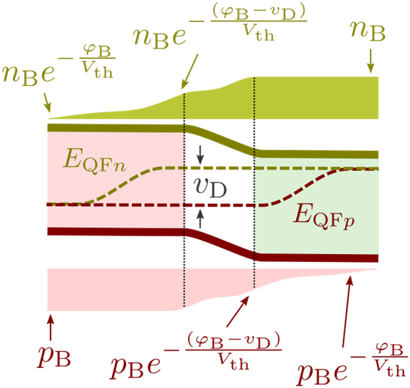
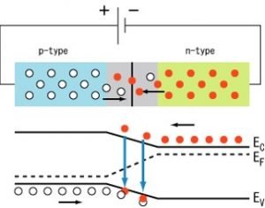
- Working principle of Varactor diode
- Symbol of Varactor diode
- I-V Characteristic of Variable diode
- Structure of Varactor Diode
- Ohmic loss in Variable diode
- Advantages of Varactor diode
- Important applications of Variable diode
What is Varactor Diode?
Definition of a Varactor Diode:
“The term varactor is the shortened form of a variable reactor, which refers to the voltage-variable capacitance of a reverse-biased p-n junction.”
Varactor diode is also known as a variable diode, vericap diode, tuning diode, variable reactance diode, or variable capacitance diode.
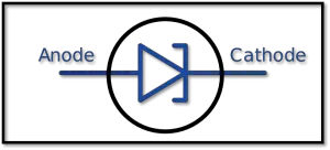
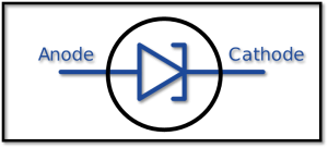
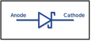
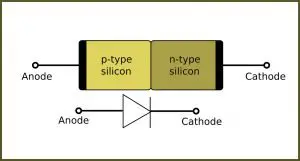
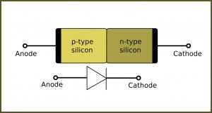
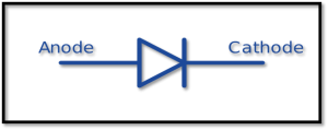
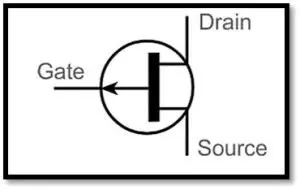
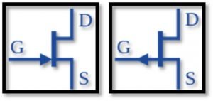
Symbol of Varactor Diode:

How does a varactor diode work?
Working principle of varactor diode:
At this point the junction capacitance be influenced by on the instigated voltage and the design parameter of the junction. A junction with constant reverse biasing can be utilized as a capacitance. Usually, the variable diode is designed to employ the voltage-variable characteristics of junction capacitance. For instance, a varactor may be hand-me-down in the radio receiver’s tuning stage to supplementary of the large variable plate capacitor. The measurement of the resulting circuit can be reduced, and its dependability is increased. All the uses of varactor diode comprise with harmonic generation, microwave frequency amplification, and active filter applications. In an abrupt P-N junction, the capacitance changes as the reverse bias Vr‘s square root.
In a graded junction, the capacitance can regularly be written as,
Cj∝ Vr-n for the condition Vr >>V0
In a linearly categorized junction, the exponent n is always one-third. That’s why, varactor diodes are prepared by ‘ the epitaxial growth methodology’ or by ‘the ion implantation technique’. The epitaxial layer can be devised to get junctions for which the exponent n is more significant than one-half. Such junctions are called hyper abrupt junctions.
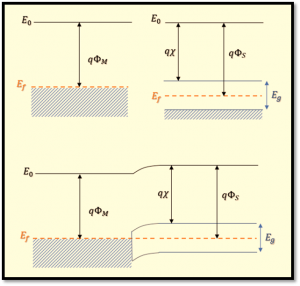
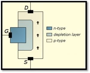
Structure of Varactor Diode

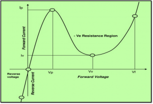
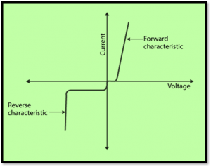
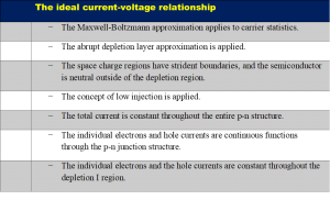
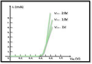
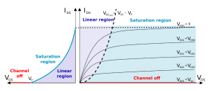
I-V Characteristic of Varactor Diode:

Doping Profiles of Varactor Diode

Three different doping profiles has been explained above with the junction is devalued as p+ -n so that the depletion layer width W is extended originally into the n side. We can observe that the exponent n is 1/(m + 2) for the p+-n junction.
The hyper abrupt junction16 with m = -3/2 is particularly interesting for specific varactor applications for this case, n = 2, and the capacitance is equivalent to Vr-2. If a capacitor is connected with an inductor L in a resonant circuit, the resonant frequency varies linearly with diode’s applied voltage.

For the reason that of the wide variability of Cj vs. Vr reliance on doping profiles selection, variable diodes can be utilized in various specific uses. In one of these case, varactors can be designed to exploit the forward-bias charge storage capacitance for high-frequency applications.
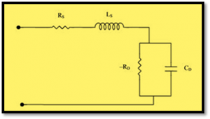
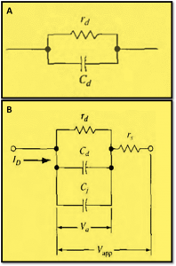
Ohmic Loss of Varactor Diode:
While deriving the diode equation, we assumed that the device’s voltage appears solely over the junction. For most of these diode, the voltage drop in the neutral regions are negligible and the doping require is comparatively higher. The resistivity of each of the neutral region is small, and a characteristic diode area is outsized compared to the length.
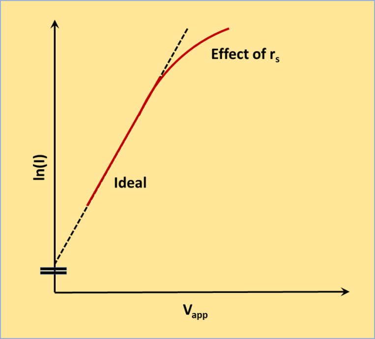
Sometimes the ohmic loss is explained in a diode by inclusion of a simple resistance in series with the junction. The effects of voltage drop exterior to the development region are important because the voltage decline be influenced on the current, explained by the voltage across the junction. For instance, if we expressed the series resistance of a p and n constituencies by Rp and Rn, correspondingly, the junction voltage V is
V = Va – I[Rp(I) + Rn(I)]
Where Va is a voltage applied externally to the device. There is a on the rise voltage drop in the resistance region Rp and Rn correspondingly when the current become higher and the junction voltage V is declined. An additional complication of loss calculation may occur if conductivity has been increased in neutral region with cumulative carrier injection. Though, at high injection levels, with the injected surplus carriers’ conductivity inflection can reduce Rp and Rn considerably. The Ohmic losses are often avoided in properly-outlined devices. For that reason, deviations of the current in general give the impression only for very high currents operating beyond regular region.
The forward and reverses current-voltage characteristics in a semi-log scale

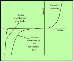
The forward and reverses current-voltage characteristics of a p-n junction on a semi-log scale has been explained above. We observe a straight line on a semi-log plot for the ideal forward-biased diode, corresponding the exponential relationship of current on voltage. Considering the second-order properties, we realize different operation modes. The enhanced generation–recombination current is directed to a further distinguished diode with ‘ideality factor’ (n = 2). For neutral currents, we get an excellent low-level injection and diffusion-limited current (n = 1). At more currents, we can get a higher injection level and n = 2, while at even greater currents, the ohmic drops initiated and space charge-neutral regions become critical.
At reverse biasing, a constant reverse saturation current has been observed, during this current is independent to voltage change. However, in substance, we receive an increased, voltage-dependent leakage current. The avalanche or Zener effects cause break down in sufficiently high reverse biasing.
Advantages of using a Varactor Diode:
Since the varactor diode has low noise compared to the p-n junction diode, there is less power loss in this diode. variable diodes are lightweight and easily portable due to its small size.
Applications of Varactor Diode:
- variable diodes are used in a variable resistant tank, which is generally an L-C circuit.
- variable diode can be used as a frequency modulator.
- It is used as RF phase shifter.
- variable diodes are utilized in a microwave receiver.

For more Electronics related article click here
