Is Malleability A Physical Property: How, Why And Detailed Facts

This article focuses on the regions dealing with Malleability, a physical property of matter.

Malleability is the ability or tendency of a material to undergo a change in shape or to get flattened when compression stress is imposed on it. i.e., the easiness showed by the material to get hammered, rolled or pressed into the form of thin sheets without any breakage.

In the following section, let us discuss the detailed facts of Malleability, a physical property.

Is Malleability a physical property?

Malleability (ability to be shaped) is undoubtedly a physical property.

Malleability can be observed and even measured without changing the matter into another substance. This nature of Malleability makes it a physical property of matter. The ability of matter to get moulded or transformed into thin sheets is usually done by making it lighter using any tool such as a hammer or rollers that make the metal thinner by pressing it.

One can declare the characteristic of a material to exhibit Malleability as a physical property by studying its nature.

Further, we can now know a detailed explanation of how Malleability is a physical property.

How Is Malleability a physical property?

The definition of Malleability itself depicts that it is related to the physical structure and behaviour.

Malleability, a physical property – a brief description of this and facts that pave the way for it is given below, A chemical reaction is not required to observe or calculate Malleability, i.e., the matter is not transformed into a new substance, but only its physical appearance (shape) is varied.

In the case of brittle or so-called hard metals, when imposed by force, they will quickly get distorted and found to break into pieces as those metals are not strong enough to withstand that force; this explains that indeed there is a change in the substance physically.

 The upcoming region contributes to the discussion of change in Malleability, being a physical property.

 Read more: Is hardness a physical property

Is change in Malleability a physical property?

The change in Malleability is regarded as a physical property.

Malleability changes are related to physical concepts of matter. Since a closely packed structure of molecules is seen in metals when they get hammered. The molecules start to disperse in all possible directions (but will not get entirely separated from each other) due to the applied force or pressure, which is taken to be a physical deviation from the original structure.

How is a change in Malleability a physical property?

It is found that after completing the whole process, the same old substance will be present.

One could achieve the ability of the metal to withstand stress by varying the strength of metallic bonds present in the matter and by varying the temperature of the surrounding in which the given metal is placed. A physical change such as applying force or pressure needs to be done for a substance to show Malleability a physical property and a change in exhibited Malleability

Here, we intend to know a method to measure the Malleability of a metal.

Read more: Is boiling point a physical property

How are you supposed to measure the Malleability of a metal?

The measurement of Malleability is done by considering the resistivity of metal to stress.

The prime method to measure the malleability is, by evaluating the amount of pressure or, in other words, the compressive stress a metal can withstand or resist, it is possible to know the magnitude of the Malleability of that metal. Due to the difference in crystal structures, various metals possess some differences in their Malleability.

Read more: Is density a physical property

Frequently asked questions| FAQS

 What will be the definition of Malleability?

Malleability is a physical property of metals.

In chemistry, Malleability is defined as the ability of a metal or even a metal alloy to get transformed into various other shapes by applying stress to the metal in different ways. Metals that can exhibit Malleability could be removed and elongated, pressed to be shaped in many ways to manufacture tools and equipment for application purposes in various fields.

Malleability can be defined in both physical and chemical views.

What makes a metal malleable?

Most of the metals are found to be malleable, whereas non-metals are not malleable.

The molecules can be seen in a closed pack structure in metal in all directions. A malleable metal can be stretched without any deformation or fracture in the metal; for the process of spinning, rolling, stretching, shrinking, flanging etc., this property of metals is necessary. Some prime examples of malleable metals are gold, silver, copper, aluminium and iron.

Gold, silver and platinum are considered to be the most malleable metals.

 What makes Malleability different from ductility?

Malleability and ductility differ based on the metal’s ability to take various shapes.

The properties of metal to undergo change in its appearance ( bluntly considering the shape) under stress, i.e., Malleability is the tendency that allows it to get rolled into sheets. On the other hand, ductility tells us how easily a metal gets stretched into wires without any deformations.

Both Malleability and ductility are physical properties of matter.

Is malleability a physical property
Image creditds: Pixabay free images

How can you explain Malleability on a molecular level?

The interaction of applied stress and the atoms present in the metal explains Malleability.

Atoms present in the malleable metals are forced by the compression stress to shift into a new position after rolling over each other; during this mechanism, the metallic bonds are not supposed to be broken. Now, the particles will stay in their new positions permanently.

What is the relation between the Malleability and hardness of a substance?

As the hardness of a substance increases, its Malleability is seen to decrease.

For a substance to exhibit Malleability, it must be possible to suppress the atoms of that substance to other positions without any breakage; this becomes more difficult in the case of metals that are considered hard, like antimony and bismuth. The reason is the existence of grain boundaries in which the atoms are loosely bound.

One can explain the connection between Malleability and hardness by considering the crystal structure.

How Malleability depends on temperature?

The Malleability of a substance is related directly to the temperature, i.e., as temperature increases, the material becomes more malleable.

The dependency of Malleability on temperature is associated with the behaviour of atoms when they get heated. This relation is used in deriving the practical applications out of the metals. The atoms and their behaviour are affected directly by the temperature.

After heated, the atoms gain energy are arranged more regularly, increasing the Malleability of the metal by decreasing the grain boundaries.

What are the similarities between Malleability and ductility?

Malleability and ductility have very much in common.

As we already discussed, Malleability and ductility are physical properties of matter. Some of the evident similarities are mentioned below, The cause is the free movement of outer electrons present in the atom. These properties have a similar dependency on the hardness and softness of the material.

Simultaneously, a substance can be both malleable and ductile. There occurs a change in shape and the dimension of the substance.

What kind of elements will not possess Malleability?

The possession of Malleability is decided based on the lattice arrangement in the metals.

A metal that cannot withstand stress will not be regarded as malleable. These metals will tend to break on the application of pressure since the atoms move farther or get distorted entirely due to the application of force or pressure. Thus, we cannot observe the property of Malleability in them.


Also Read:

Exploring the Magnetic Field in a Transformer: A Comprehensive Guide

magnetic field in a transformer

The magnetic field in a transformer is a crucial aspect of its operation, as it is responsible for the efficient transfer of electrical energy from the primary winding to the secondary winding. Understanding the behavior and characteristics of the magnetic field is essential for designing and optimizing transformer performance.

Magnetic Flux Density (B) and Faraday’s Law

The magnetic field in a transformer is often characterized by the magnetic flux density (B), which is the measure of the strength of the magnetic field passing through a given area. The magnetic flux density can be calculated using Faraday’s law of induction, which states that the voltage (V) induced in a coil is proportional to the rate of change of the magnetic flux (dΦ/dt) through the coil. The magnetic flux (Φ) is the product of the magnetic flux density (B) and the area (A) through which it passes, as expressed by the equation:

Φ = B × A

Faraday’s law of induction can be written as:

V = -N × (dΦ/dt)

where N is the number of turns in the coil.

Magnetic Field Generation in a Transformer

magnetic field in a transformer

In a transformer, the primary winding generates a magnetic field when a current flows through it. This magnetic field induces a voltage in the secondary winding, which can be used to transfer power from the primary to the secondary winding. The magnetic flux density (B) in a transformer is determined by several factors:

  1. Number of Turns in the Windings: The number of turns in the primary and secondary windings directly affects the magnetic flux density. Increasing the number of turns in the primary winding will increase the magnetic flux density, while increasing the number of turns in the secondary winding will decrease the magnetic flux density.

  2. Current in the Primary Winding: The current flowing through the primary winding is another factor that determines the magnetic flux density. As the current increases, the magnetic flux density also increases, as described by the equation:

B = μ × N × I / l

where μ is the magnetic permeability of the core material, N is the number of turns in the primary winding, I is the current in the primary winding, and l is the length of the magnetic path.

  1. Magnetic Properties of the Core Material: The magnetic properties of the core material, such as its permeability and saturation flux density, also play a crucial role in determining the magnetic flux density. Ferromagnetic materials, such as silicon steel, are commonly used in transformer cores due to their high permeability and low losses.

Measuring the Magnetic Field in a Transformer

The magnetic field in a transformer can be quantified by measuring the magnetic flux density (B) and the magnetic field strength (H) at various points within the transformer. Several techniques can be used for these measurements:

  1. Hall Effect Sensors: Hall effect sensors measure the voltage generated by the magnetic field perpendicular to the direction of current flow in a conductive material. They can be used to measure the magnetic flux density (B) at specific locations within the transformer.

  2. Fluxgate Magnetometers: Fluxgate magnetometers measure the magnetic field by detecting the distortion of a magnetic field produced by a coil wrapped around a magnetically permeable core. They can be used to measure both the magnitude and direction of the magnetic field.

  3. Search Coils: Search coils measure the voltage induced in a coil by a changing magnetic field. They can be used to measure the rate of change of the magnetic flux (dΦ/dt), which can then be used to calculate the magnetic flux density (B) using Faraday’s law.

  4. Induction Coils, Rogowski Coils, and Current Transformers: These devices can be used to measure the magnetic field strength (H) by measuring the current or voltage induced in the coils due to the changing magnetic field.

Magnetic Field Distribution and Visualization

In addition to measuring the magnetic field strength and flux density, it is also important to consider the distribution of the magnetic field within the transformer. The magnetic field distribution can be visualized using magnetic field plots, which show the magnetic field strength or flux density at various points within the transformer.

Magnetic field plots can be used to identify areas of high magnetic field strength or flux density, which can be a source of heat generation and energy loss in the transformer. These areas of high magnetic field can lead to increased core losses, eddy current losses, and hysteresis losses, all of which can reduce the overall efficiency of the transformer.

Frequency Dependence of the Magnetic Field

The magnetic field in a transformer can vary at different frequencies, depending on the operating conditions of the transformer. Measuring the magnetic field at different frequencies can help to identify any frequency-dependent effects, such as resonances or harmonic distortion.

For example, at higher frequencies, the skin effect and proximity effect can become more pronounced, leading to increased eddy current losses in the transformer windings and core. Measuring the magnetic field at these higher frequencies can help to quantify the impact of these effects and inform the design of the transformer to mitigate them.

Numerical Examples and Data Points

To illustrate the concepts discussed, let’s consider a few numerical examples and data points related to the magnetic field in a transformer:

  1. Magnetic Flux Density Calculation: Consider a transformer with a primary winding of 500 turns and a secondary winding of 50 turns. If the primary winding carries a current of 10 A and the cross-sectional area of the core is 50 cm^2, the magnetic flux density can be calculated as:

B = μ × N × I / l
B = 4π × 10^-7 H/m × 500 × 10 A / 0.1 m
B = 0.314 T

  1. Magnetic Field Strength Measurement: Using a Rogowski coil, the magnetic field strength (H) in a transformer core was measured to be 800 A/m. Assuming a relative permeability (μ_r) of the core material as 2000, the magnetic flux density (B) can be calculated as:

B = μ × H
B = 4π × 10^-7 H/m × 2000 × 800 A/m
B = 1.005 T

  1. Magnetic Field Distribution: A magnetic field plot of a transformer core revealed that the magnetic flux density was highest near the corners of the core, reaching values up to 1.2 T. This uneven distribution of the magnetic field can lead to increased core losses and localized heating in the transformer.

  2. Frequency Dependence: Measurements of the magnetic field in a transformer at different frequencies showed that the magnetic flux density decreased by 5% when the frequency was increased from 50 Hz to 400 Hz. This frequency-dependent behavior is due to the skin effect and proximity effect, which become more pronounced at higher frequencies.

These examples and data points illustrate the importance of understanding and quantifying the magnetic field in a transformer for optimizing its design and performance.

Conclusion

The magnetic field in a transformer is a complex and multifaceted phenomenon that plays a crucial role in the efficient operation of the device. By understanding the factors that influence the magnetic field, such as the number of turns, current, and core material properties, as well as the techniques for measuring and visualizing the magnetic field, engineers can design more efficient and reliable transformers for a wide range of applications.

References

  1. Transformer Magnetic Fields and Cans / Covers – diyAudio
  2. Induction in transformer coil relationship to magnetic field lines in core – Electronics Stack Exchange
  3. Magnetic flux and current directions of transformer – Physics Forums
  4. Magnetic Field Evaluation in Transformers and Inductors – Texas Instruments
  5. Measurement of Magnetic and Magnetostrictive Characteristics of … – National Center for Biotechnology Information

The State of Static Equilibrium: A Comprehensive Guide for Physics Students

state of static equilibrium

The state of static equilibrium is a fundamental concept in physics that describes a situation where an object is at rest, and all the forces acting on it are balanced, resulting in zero net force and zero acceleration. This concept is a direct application of Newton’s first law of motion, which states that an object at rest tends to stay at rest, and an object in motion tends to stay in motion, unless acted upon by an external force.

Understanding the Principles of Static Equilibrium

To understand the state of static equilibrium, it is essential to grasp the underlying principles and the mathematical relationships involved.

Newton’s First Law of Motion

The state of static equilibrium is a direct consequence of Newton’s first law of motion, also known as the law of inertia. This law states that an object at rest will remain at rest, and an object in motion will continue to move at a constant velocity, unless acted upon by an unbalanced force.

In the state of static equilibrium, the net force acting on an object is zero, meaning that the object will remain at rest, as per Newton’s first law.

Conditions for Static Equilibrium

For an object to be in a state of static equilibrium, two conditions must be met:

  1. The vector sum of all the forces acting on the object must be zero.
  2. This means that the net force acting on the object is zero, and the object will not experience any acceleration.
  3. Mathematically, this can be expressed as:
    ΣF_x = 0
    ΣF_y = 0
  4. Where ΣF_x and ΣF_y represent the sum of all the forces acting on the object in the x and y directions, respectively.

  5. The net torque acting on the object must be zero.

  6. Torque is a measure of the tendency of a force to cause rotational motion about a specific point.
  7. For an object to be in static equilibrium, the net torque acting on it must be zero, meaning that the object will not experience any rotational acceleration.
  8. Mathematically, this can be expressed as:
    Στ = 0
  9. Where Στ represents the sum of all the torques acting on the object.

Analyzing Forces in Static Equilibrium

When an object is in a state of static equilibrium, the forces acting on it can be analyzed using vector addition or by resolving each force into its horizontal and vertical components.

Vector Addition

The vector sum of all the forces acting on the object should be zero, indicating that the net force is balanced. This can be achieved by adding the vectors representing the forces acting on the object, ensuring that the resultant vector is zero.

Resolving Forces into Components

Alternatively, the forces acting on the object can be resolved into their horizontal and vertical components. The sum of the horizontal components and the sum of the vertical components should both be zero, indicating that the forces are balanced.

This approach is particularly useful when the forces are acting at angles, as it allows for a more intuitive analysis of the force balance.

Experimental Verification of Static Equilibrium

A common physics lab involves hanging an object by two or more strings and measuring the forces exerted at angles upon the object to support its weight. By analyzing the forces acting on the object, students can determine if the object is in a state of static equilibrium.

If the net force acting on the object is zero, then the object is at equilibrium. Conversely, if the components of the forces only nearly balance, it suggests experimental error in the measurement of the forces.

Applications of Static Equilibrium

state of static equilibrium

The state of static equilibrium is widely applicable in various physical situations, ranging from everyday scenarios to complex engineering problems.

Constant-Speed Motion on a Straight, Level Road

A car moving with constant speed along a straight, level road is in a state of static equilibrium. The balanced forces acting on the car include the forward force of the engine, the rolling resistance, and the force of air resistance. As long as these forces are balanced, the car will maintain a constant speed.

Projectile Motion at the Highest Point

At the highest point of a projectile’s trajectory, the object is in a state of static equilibrium. The downward force of gravity is balanced by the upward force of air resistance, resulting in zero net force and zero acceleration.

Structural Analysis and Design

The principles of static equilibrium are crucial in the analysis and design of structures, such as bridges, buildings, and cranes. Engineers use these principles to ensure that the forces acting on a structure are balanced, preventing collapse or deformation.

Mechanical Systems and Machines

Static equilibrium is also essential in the design and analysis of mechanical systems and machines. For example, in the case of a pulley system, the forces acting on the pulleys and the suspended object must be in a state of static equilibrium to ensure proper functioning.

Biomechanics and Ergonomics

The concept of static equilibrium is also applicable in the field of biomechanics and ergonomics. When analyzing the human body’s posture and movement, the forces acting on the various body parts must be in a state of static equilibrium to maintain balance and stability.

Numerical Examples and Problem-Solving Techniques

To solidify the understanding of the state of static equilibrium, it is essential to work through numerical examples and practice problem-solving techniques.

Example 1: Analyzing Forces on a Suspended Object

Consider an object suspended by two strings, as shown in the figure below. The object has a mass of 10 kg, and the strings are attached at angles of 30° and 45° with respect to the horizontal.

Suspended Object

Given:
– Mass of the object, m = 10 kg
– Angle of the first string, θ1 = 30°
– Angle of the second string, θ2 = 45°

Determine the tension in each string to maintain the object in static equilibrium.

Solution:
1. Identify the forces acting on the object:
– Gravitational force (weight), F_g = m * g = 10 kg * 9.8 m/s^2 = 98 N
– Tension in the first string, T_1
– Tension in the second string, T_2

  1. Resolve the forces into horizontal and vertical components:
  2. Horizontal components:
    • T_1 * cos(30°) + T_2 * cos(45°) = 0
  3. Vertical components:

    • T_1 * sin(30°) + T_2 * sin(45°) = F_g
  4. Solve the system of equations to find the tensions:

  5. T_1 = 113 N
  6. T_2 = 98 N

Therefore, the tension in the first string is 113 N, and the tension in the second string is 98 N to maintain the object in static equilibrium.

Example 2: Analyzing Forces on a Ladder

Consider a ladder leaning against a wall, as shown in the figure below. The ladder has a mass of 20 kg, and it makes an angle of 60° with the horizontal. The coefficient of friction between the ladder and the wall is 0.3, and the coefficient of friction between the ladder and the ground is 0.4.

Ladder against a Wall

Determine the normal force exerted by the wall on the ladder and the normal force exerted by the ground on the ladder to maintain the ladder in static equilibrium.

Solution:
1. Identify the forces acting on the ladder:
– Gravitational force (weight), F_g = m * g = 20 kg * 9.8 m/s^2 = 196 N
– Normal force from the wall, N_w
– Normal force from the ground, N_g
– Frictional force from the wall, F_fw = μ_w * N_w
– Frictional force from the ground, F_fg = μ_g * N_g

  1. Resolve the forces into horizontal and vertical components:
  2. Horizontal components:
    • F_fw - F_fg = 0
  3. Vertical components:

    • N_w + N_g - F_g = 0
  4. Solve the system of equations to find the normal forces:

  5. N_w = 113 N
  6. N_g = 196 N

Therefore, the normal force exerted by the wall on the ladder is 113 N, and the normal force exerted by the ground on the ladder is 196 N to maintain the ladder in static equilibrium.

These examples demonstrate the application of the principles of static equilibrium in analyzing the forces acting on various physical systems. By working through such examples, students can develop a deeper understanding of the concept and improve their problem-solving skills.

Conclusion

The state of static equilibrium is a fundamental concept in physics that underpins various physical phenomena. By understanding the principles of static equilibrium, including the conditions for equilibrium, the analysis of forces, and the applications in different scenarios, students can develop a strong foundation in classical mechanics and apply these principles to solve a wide range of problems.

Through the examples and problem-solving techniques presented in this guide, students can gain practical experience in analyzing and determining the forces acting on objects in a state of static equilibrium. This knowledge is essential for success in physics courses, as well as in various engineering and scientific fields that rely on the principles of classical mechanics.

References

  1. APlusPhysics. (n.d.). Static Equilibrium. Retrieved from https://www.aplusphysics.com/courses/honors/dynamics/static_eq.html
  2. Course Hero. (n.d.). PHYS207 Lab 6 Static Equilibrium Instructional Goals. Retrieved from https://www.coursehero.com/file/22009817/6-Static-Equilibrium/
  3. The Physics Classroom. (n.d.). Equilibrium and Statics. Retrieved from https://www.physicsclassroom.com/class/vectors/Lesson-3/Equilibrium-and-Statics
  4. Serway, R. A., & Jewett, J. W. (2018). Physics for Scientists and Engineers with Modern Physics (10th ed.). Cengage Learning.
  5. Halliday, D., Resnick, R., & Walker, J. (2013). Fundamentals of Physics (10th ed.). Wiley.

Dynamic Equilibrium in Solution: A Comprehensive Guide

dynamic equilibrium in solution

Dynamic equilibrium in solution is a fundamental concept in chemistry that describes the state where the forward and reverse reactions occur at equal rates, resulting in no net change in the concentrations of reactants and products. This concept is crucial in understanding various chemical reactions, particularly those involving acid-base equilibria. In this comprehensive guide, we will delve into the intricacies of dynamic equilibrium in solution, providing a wealth of technical and advanced details to help you gain a deeper understanding of this important topic.

Understanding Dynamic Equilibrium

Dynamic equilibrium in a solution occurs when the rate of the forward reaction is equal to the rate of the reverse reaction. This means that the concentrations of the reactants and products remain constant over time, even though the individual molecules are continuously undergoing the forward and reverse reactions.

The key characteristics of dynamic equilibrium in solution are:

  1. Constant Concentrations: The concentrations of the reactants and products remain constant at equilibrium, despite the ongoing forward and reverse reactions.
  2. Equal Rates: The rate of the forward reaction is equal to the rate of the reverse reaction, resulting in no net change in the concentrations.
  3. Reversible Reactions: Dynamic equilibrium can only be achieved in reversible reactions, where the forward and reverse reactions can both occur.
  4. Temperature Dependence: The equilibrium constant (Keq) for a reaction is temperature-dependent, meaning that changes in temperature can shift the position of the equilibrium.

Equilibrium Constant (Keq)

dynamic equilibrium in solution

The equilibrium constant (Keq) is a quantitative measure of the extent of a reaction at equilibrium. It is defined as the ratio of the concentrations of the products raised to their stoichiometric coefficients to the concentrations of the reactants raised to their stoichiometric coefficients, all at equilibrium.

The general expression for the equilibrium constant is:

Keq = [C]^c * [D]^d / ([A]^a * [B]^b)

Where:
– [A], [B], [C], and [D] are the equilibrium concentrations of the reactants and products
– a, b, c, and d are the stoichiometric coefficients of the reactants and products

The equilibrium constant is a constant for a particular reaction at a given temperature and does not depend on the initial concentrations of the reactants or products.

Factors Affecting Equilibrium Constant

The value of the equilibrium constant (Keq) can be affected by several factors:

  1. Temperature: The equilibrium constant is temperature-dependent. As the temperature changes, the value of Keq will also change, following the van ‘t Hoff equation:

ln(Keq2/Keq1) = -ΔH°/R * (1/T2 – 1/T1)

Where:
– Keq1 and Keq2 are the equilibrium constants at temperatures T1 and T2, respectively
– ΔH° is the standard enthalpy change of the reaction
– R is the universal gas constant

  1. Pressure: For reactions involving gases, the equilibrium constant can be affected by changes in pressure. However, for reactions in solution, the effect of pressure is generally negligible.
  2. Ionic Strength: In solutions with high ionic strength, the activity coefficients of the ions can affect the equilibrium constant, leading to deviations from the ideal behavior.

Calculating Equilibrium Constant

The equilibrium constant (Keq) can be calculated using the following steps:

  1. Write the balanced chemical equation for the reaction.
  2. Identify the stoichiometric coefficients of the reactants and products.
  3. Measure the equilibrium concentrations of the reactants and products.
  4. Substitute the equilibrium concentrations into the equilibrium constant expression and calculate the value of Keq.

For example, consider the reaction:

H2(g) + I2(g) ⇌ 2HI(g)

At equilibrium, the concentrations are:
[H2] = 0.2 M
[I2] = 0.1 M
[HI] = 0.6 M

The equilibrium constant can be calculated as:

Keq = [HI]^2 / ([H2] * [I2])
Keq = (0.6)^2 / (0.2 * 0.1)
Keq = 0.36 / 0.02
Keq = 18

Acid-Base Equilibria

In the context of acid-base equilibria, the equilibrium constant is often referred to as the acid dissociation constant (Ka) or the base dissociation constant (Kb). These constants are used to quantify the strength of acids and bases, respectively.

Acid Dissociation Constant (Ka)

The acid dissociation constant (Ka) is the equilibrium constant for the dissociation of an acid in water. It is defined as the ratio of the concentrations of the dissociated products (H+ and the conjugate base) to the concentration of the undissociated acid at equilibrium.

The general expression for the acid dissociation constant is:

Ka = [H+] * [A-] / [HA]

Where:
– [H+] is the equilibrium concentration of hydrogen ions
– [A-] is the equilibrium concentration of the conjugate base
– [HA] is the equilibrium concentration of the undissociated acid

The value of Ka provides information about the strength of the acid. A larger Ka value indicates a stronger acid, as it dissociates more in water.

Base Dissociation Constant (Kb)

The base dissociation constant (Kb) is the equilibrium constant for the dissociation of a base in water. It is defined as the ratio of the concentrations of the dissociated products (the conjugate base and OH-) to the concentration of the undissociated base at equilibrium.

The general expression for the base dissociation constant is:

Kb = [B-] * [OH-] / [B]

Where:
– [B-] is the equilibrium concentration of the conjugate base
– [OH-] is the equilibrium concentration of hydroxide ions
– [B] is the equilibrium concentration of the undissociated base

The value of Kb provides information about the strength of the base. A larger Kb value indicates a stronger base, as it dissociates more in water.

Applications of Dynamic Equilibrium in Solution

Dynamic equilibrium in solution has numerous applications in various fields of chemistry, including:

  1. Acid-Base Titrations: The concept of dynamic equilibrium is crucial in understanding the behavior of acids and bases during titrations, which are used to determine the concentration of an unknown acid or base.
  2. Buffer Solutions: Buffer solutions maintain a relatively constant pH by utilizing the dynamic equilibrium between an acid and its conjugate base or a base and its conjugate acid.
  3. Solubility Equilibria: The solubility of sparingly soluble salts in water is governed by dynamic equilibrium, which can be described using the solubility product constant (Ksp).
  4. Precipitation Reactions: Dynamic equilibrium plays a role in precipitation reactions, where the formation and dissolution of precipitates are in equilibrium.
  5. Biological Systems: Many biological processes, such as the regulation of pH in the human body, involve dynamic equilibria in solution.

Conclusion

Dynamic equilibrium in solution is a fundamental concept in chemistry that describes the state where the forward and reverse reactions occur at equal rates, resulting in no net change in the concentrations of reactants and products. Understanding the principles of dynamic equilibrium, the equilibrium constant (Keq), and its applications in various chemical systems is crucial for students and researchers in the field of chemistry.

This comprehensive guide has provided a wealth of technical and advanced details on dynamic equilibrium in solution, including the factors affecting the equilibrium constant, the calculation of Keq, and the specific applications in acid-base equilibria and other chemical systems. By mastering the concepts presented in this guide, you will be well-equipped to tackle complex problems and deepen your understanding of the dynamic nature of chemical reactions in solution.

Reference:

  1. Dynamic Equilibrium – Chemistry LibreTexts
  2. Acid-Base Equilibrium – Chemistry LibreTexts
  3. Equilibria 16–18 | Resource – RSC Education
  4. Equilibrium Constant (Keq) – Chemistry LibreTexts
  5. Acid Dissociation Constant (Ka) – Chemistry LibreTexts
  6. Base Dissociation Constant (Kb) – Chemistry LibreTexts

7 Important Chemical Equilibrium Examples You Should Know

acid and base

In the present article, we intend to discuss about the important chemical equilibrium examples you should know. We can always witness a state corresponding to a system in which it is found that the reactant concentration and the product concentration both evidently remain unchanged and also further more changes across properties cannot be seen to occur in correspondence to the system.

  • Ionization of acids and bases
  • Buffer solution
  • Methanol production
  • Ethanol production
  • Ammonia production
  • Solubility equilibria
  • Equilibrium in chemical processes

Ionization of acids and bases

Here, we can say that there is a splitting up of molecules that are generally neutral giving rise to the charged ions when they come in contact with the solution is itself the ionization. In this case, there occurs a point at which we can see a rate of both forward as well as backward reactions to be same.

Thus, is nothing but the chemical equilibrium. i.e., the expenditure of reactants in the reaction is compromised by the reverse reaction producing the same without any loss. It is one of the chemical equilibrium examples.

At such equilibrium point, there will be no variation in the concentration of the reactants as well as the products in accordance with time. In the aqueous medium there will be a production of hydrogen ions when dissociation of the acids takes place in that medium.

acid and base
Image credits: Pixabay free images

Buffer solution

For the functioning of cells to be normal we need to maintain the pH of the respective substance. For this purpose, we require a solution generally referred as a buffer. Even in several chemical as well as biochemical processes also we may find a prime utility of the buffer solution. This is because of the mandatory need to control the pH. 

The ideal pH of blood so that there is a normal functioning in the human body is found to be 7.35. By the use of buffer solution, the reactant concentration and the product concentration both evidently remain unchanged and also further more changes across properties cannot be seen to occur in correspondence to the system. It is one of the chemical equilibrium examples.

blood
Image credits: Pixabay free images

Methanol production

The conditions that are experimentally found to be favourable for the production are referred as the compromise conditions. The forward reaction in turn the production of methanol is usually favoured by a temperature that is comparatively lower which is around 500K as the forward reaction that is responsible for generating a lesser moles of gas  is recognized to be an exothermic reaction.

Along with lower temperature, a higher pressure is also found to be in favour of the forward reaction. A copper catalyst may be of great use in order to increase the rection rate. It is one of the chemical equilibrium examples.

Ethanol production

The conditions that are experimentally found to be favourable for the production are referred as the compromise conditions. The forward reaction in turn the production of ethanol is usually favoured by a temperature that is comparatively lower approximately 570K as the forward reaction that is responsible for generating a lesser moles of gas is recognized to be an exothermic reaction.

Along with lower temperature, a higher pressure is also found to be in favour of the forward reaction. A phosphoric acid catalyst may be of great use in order to increase the rection rate. It is one of the examples of chemical equilibrium examples.

Ammonia production

The conditions that are experimentally found to be favourable for the production are referred as the compromise conditions. The forward reaction in turn the production of ammonia is usually favoured by a temperature that is comparatively lower i.e., around 670K as the forward reaction that is responsible for generating a lesser moles of gas is recognized to be an exothermic reaction.

Along with lower temperature, a higher pressure is also found to be in favour of the forward reaction. A iron catalyst may be of great use in order to increase the rection rate. It is one of the chemical equilibrium examples.

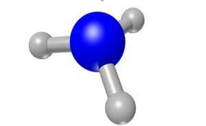
ammonia
Image credits: Pixabay free images

Solubility equilibria

In this case, the considered solid molecules intend to produce individual molecules that are found to be aqueous by undergoing the process of dissolving. Below given reaction is an example for the same,

H2O
C12H22O11(S) —————> C12H22O11 (aq)

Whereas, there is a production of positive as well as the negative ions separately by the occurrence of dissociation of ionic solids. i.e.,

 NaCl (s) ————————-> Na + (aq) + Cl  (aq )

The salt solutions are experimentally recognized to be a good conductors corresponding to the electricity as thus formed ions are responsible for carrying the electric current. It is one of the examples of chemical equilibrium examples.

examples of chemical equilibrium
Image credits: Pixabay free images

Equilibrium in chemical processes

We can always witness a state corresponding to a chemical reaction in which it is found that the reactant concentration and the product concentration both evidently remain unchanged and also further more changes across properties cannot be seen to occur in correspondence to the system.

As we all know, in chemical reactions we find the interconversion of products and reactants through forward and backward reactions respectively.

There occurs a point at which we can see a same rate of both forward and backward reactions. Thus, is nothing but the chemical equilibrium. i.e., the expenditure of amount of reactants in the reaction is compromised by the reverse reaction producing the same without any loss. It is one of the chemical equilibrium examples.

reaction 1
Image credits: Pixabay free images


What are the different types that are associated with the chemical equilibrium?

In general, we can witness two types of chemical equilibrium. i.e.,

  • Homogeneous equilibrium
  • Heterogeneous equilibrium

Homogeneous equilibrium

In this type of chemical equilibrium, we may observe that the products of the reaction happen to be in the same phase as that of the reactants.

 Heterogeneous equilibrium

In this type of chemical equilibrium, we may observe that the products of the reaction happen to be in a different phase when compared to that of the reactants.

Why chemical equilibrium is dynamic?

The chemical equilibrium can also be called as the dynamic equilibrium as, As we all know, in chemical reactions we find the interconversion of products and reactants through forward and backward reactions respectively.

There occurs a point at which we can see a same rate of both forward and backward reactions. Thus, is nothing but the chemical equilibrium. i.e., the expenditure of amount of reactants in the reaction is compromised by the reverse reaction producing the same without any loss.

Name the factors that influence the chemical equilibrium.

The factors that are proved to be influencing the chemical equilibrium are,

  • Change in concentration
  • Pressure change
  • Temperature change
  • Effect of catalyst
  • Addition of acids and bases

What do you mean by chemical equilibrium?

We can always witness a state corresponding to a system in which it is found that the reactant concentration and the product concentration both evidently remain unchanged and also further more changes across properties cannot be seen to occur in correspondence to the system.

As we all know, in chemical reactions we find the interconversion of products and reactants through forward and backward reactions respectively.

There occurs a point at which we can see the same rate of both forward and backward reactions. Thus, it is nothing but the chemical equilibrium. i.e., the expenditure of the number of reactants in the reaction is compromised by the reverse reaction producing the same without any loss.

Conclusion

As we all know, in chemical reactions we find the interconversion of products and reactants through forward and backward reactions respectively. There occurs a point at which we can see a same rate of both forward and backward reactions. Thus, is nothing but the chemical equilibrium.

Read more about Is Chemical Equilibrium a Dynamic Equilibrium?

Also Read:

Is Centripetal Acceleration a Vector?

is centripetal acceleration a vector

Centripetal acceleration is a fundamental concept in physics that describes the acceleration experienced by an object moving in a circular path. This acceleration is always directed towards the center of the circular motion, making it a vector quantity. In this comprehensive guide, we will delve into the details of centripetal acceleration, its mathematical formulation, and its applications in various scenarios.

Understanding Centripetal Acceleration

Centripetal acceleration is the acceleration experienced by an object moving in a circular path. It is directed towards the center of the circle and is responsible for the object’s change in direction, rather than its change in speed. The magnitude of centripetal acceleration depends on the object’s velocity and the radius of the circular path.

The formula for centripetal acceleration is:

$a_c = \frac{v^2}{r}$

where:
– $a_c$ is the centripetal acceleration (in m/s²)
– $v$ is the velocity of the object (in m/s)
– $r$ is the radius of the circular path (in m)

This formula clearly shows that centripetal acceleration is a vector quantity, as it has both magnitude and direction. The direction of the centripetal acceleration is always towards the center of the circular path, while the magnitude depends on the object’s velocity and the radius of the circular motion.

Uniform Circular Motion

is centripetal acceleration a vector

In the case of uniform circular motion, where the object’s speed remains constant, the centripetal acceleration can be calculated using the formula:

$a_c = \frac{v^2}{r}$

Here, the velocity $v$ is the constant linear velocity of the object, and $r$ is the radius of the circular path.

For example, consider a car moving at a constant speed of 20 m/s on a circular road with a radius of 50 m. The centripetal acceleration experienced by the car would be:

$a_c = \frac{(20 \text{ m/s})^2}{50 \text{ m}} = 8 \text{ m/s}^2$

The direction of this centripetal acceleration is always towards the center of the circular path.

Non-uniform Circular Motion

In the case of non-uniform circular motion, where the object’s speed is changing, the formula for centripetal acceleration becomes more complex:

$a_c = \omega^2 r + 2\omega v + \alpha r$

where:
– $\omega$ is the angular velocity of the object (in rad/s)
– $v$ is the linear velocity of the object (in m/s)
– $r$ is the radius of the circular path (in m)
– $\alpha$ is the angular acceleration of the object (in rad/s²)

This formula takes into account the changing velocity and radius of the circular path, allowing us to calculate the centripetal acceleration in non-uniform circular motion.

For example, consider a satellite orbiting the Earth with a varying velocity and radius. The centripetal acceleration experienced by the satellite would be calculated using the above formula, taking into account the changes in its angular velocity, linear velocity, and the radius of its orbit.

Centripetal Acceleration in Real-World Applications

Centripetal acceleration is a fundamental concept in many areas of physics and engineering, including:

  1. Circular Motion in Vehicles: Centripetal acceleration is responsible for the forces experienced by passengers in vehicles making turns, such as cars, trains, and roller coasters.

  2. Satellite Orbits: Centripetal acceleration is crucial in the analysis of satellite orbits, where the satellite’s motion is governed by the balance between centripetal acceleration and gravitational forces.

  3. Rotational Machinery: Centripetal acceleration plays a role in the design and analysis of rotating machinery, such as turbines, centrifuges, and flywheels.

  4. Particle Accelerators: In particle accelerators, such as cyclotrons and synchrotrons, charged particles are accelerated in a circular path using centripetal acceleration.

  5. Centrifugal Pumps: Centripetal acceleration is the driving force behind the operation of centrifugal pumps, which are widely used in various industrial and domestic applications.

Conclusion

In summary, centripetal acceleration is a vector quantity that always points towards the center of a circular path. Its magnitude depends on the object’s velocity and the radius of the circular motion, and it plays a crucial role in various physical phenomena and engineering applications. Understanding the concept of centripetal acceleration is essential for a comprehensive understanding of circular motion and its implications in the real world.

Reference:

  1. Centripetal Acceleration | Definition, Equation & Formula – Lesson
  2. Proof of centripetal acceleration formula ($a_c = v^2/r$) for non-uniform circular motion
  3. How does centripetal acceleration have direction/vector and magnitude while in the formula $v^2=v⋅v$ is scalar?
  4. Physics Lab Evaluation Questions Flashcards | Quizlet
  5. Centripetal Acceleration Report Sheet 1 .docx – Course Hero

Is Angular Acceleration Negative?

is angular acceleration negative

Angular acceleration can be positive, negative, or zero, and it plays a crucial role in the study of rotational motion. A negative angular acceleration indicates that the angular velocity of an object is decreasing or becoming more negative over time. This concept can be represented mathematically and has various practical applications in physics and engineering.

Understanding Negative Angular Acceleration

The relationship between angular velocity (ω), initial angular velocity (ω₀), angular acceleration (α), and time (t) can be expressed as:

ω = ω₀ + αt

When the angular acceleration (α) is negative, it means that the angular velocity (ω) is decreasing over time. This can be visualized as the object slowing down or decelerating in its rotational motion.

Negative Angular Acceleration Formula

The formula for negative angular acceleration is the same as the general formula for angular acceleration:

α = (ω – ω₀) / t

Where:
– α is the angular acceleration (in rad/s²)
– ω is the final angular velocity (in rad/s)
– ω₀ is the initial angular velocity (in rad/s)
– t is the time elapsed (in seconds)

If the final angular velocity (ω) is less than the initial angular velocity (ω₀), then the angular acceleration (α) will be negative, indicating a deceleration in the rotational motion.

Examples of Negative Angular Acceleration

  1. Rotating Disc: Suppose a rotating disc changes its angular speed from 100 rad/s to 40 rad/s in 10 seconds. The angular acceleration during this time would be:

α = (ω – ω₀) / t
α = (40 rad/s – 100 rad/s) / 10 s
α = -6 rad/s²

This means that the angular velocity of the disc is decreasing at a rate of 6 rad/s every second.

  1. Bicycle Wheel: Consider the rear wheel of a bicycle having an angular acceleration of -20 rad/s². This indicates that the angular velocity of the wheel is decreasing at a rate of 20 rad/s every second, resulting in a deceleration of the wheel’s rotational motion.

Negative Angular Acceleration in Rotational Dynamics

Negative angular acceleration is often associated with the concept of rotational dynamics, which deals with the relationship between torque, angular acceleration, and the moment of inertia of an object.

The equation of motion for rotational dynamics is:

τ = Iα

Where:
– τ is the net torque acting on the object (in N·m)
– I is the moment of inertia of the object (in kg·m²)
– α is the angular acceleration of the object (in rad/s²)

If the net torque (τ) acting on the object is in the opposite direction of the object’s angular velocity, the angular acceleration (α) will be negative, indicating a deceleration in the rotational motion.

Practical Applications of Negative Angular Acceleration

is angular acceleration negative

Negative angular acceleration has various practical applications in different fields, including:

  1. Braking Systems: In vehicles, negative angular acceleration is used in braking systems to slow down or stop the rotation of the wheels. The brake pads apply a frictional force that creates a negative torque, resulting in a negative angular acceleration and a decrease in the angular velocity of the wheels.

  2. Rotational Machinery: In industrial machinery, such as motors, generators, and turbines, negative angular acceleration is often used to control the speed and prevent damage to the system. When the load on the machine increases, the angular acceleration may become negative, causing the machine to slow down and maintain a safe operating speed.

  3. Sports and Biomechanics: In sports and human movement analysis, negative angular acceleration is observed in various activities, such as the deceleration phase of a baseball pitch, the landing phase of a gymnastic routine, or the braking action of a cyclist.

  4. Robotics and Automation: In robotic systems and automated machinery, negative angular acceleration is used to control the motion and prevent damage to the components. Precise control of angular acceleration is crucial for the smooth and safe operation of these systems.

Conclusion

In summary, angular acceleration can be positive, negative, or zero, and understanding the concept of negative angular acceleration is essential in the study of rotational motion. Negative angular acceleration indicates a decrease in the angular velocity of an object, which can be represented mathematically and has various practical applications in physics, engineering, and other related fields.

References:

Diffusion and Temperature: A Comprehensive Guide for Physics Students

diffusion and temperature

Diffusion and temperature are two closely related concepts in physics that play a crucial role in various physical and chemical processes. Understanding the intricate relationship between these two phenomena is essential for students studying physics, materials science, and related fields. This comprehensive guide will delve into the technical details, formulas, and practical applications of diffusion and temperature, providing a valuable resource for physics students.

Diffusion Coefficient: The Key to Understanding Diffusion

The diffusion coefficient is a fundamental parameter that describes the rate at which a substance spreads out in a given medium. This value can be measured in units of area per time, such as square centimeters per second (cm²/s). The diffusion coefficient is directly influenced by temperature, with higher temperatures generally leading to faster diffusion rates.

For example, in a study of diffusion in clay bricks, a diffusion coefficient of 0.014 cm²/s was measured at room temperature. This value is very close to the model prediction for the diffusion coefficient of sample A at an ambient temperature, which is 0.011 cm²/s. The diffusion coefficient can be calculated using the following formula:

D = (kB * T) / (6 * π * η * r)

Where:
– D is the diffusion coefficient (cm²/s)
– kB is the Boltzmann constant (1.38 × 10^-23 J/K)
– T is the absolute temperature (K)
– η is the dynamic viscosity of the medium (Pa·s)
– r is the radius of the diffusing particle (m)

This formula demonstrates the direct relationship between the diffusion coefficient and temperature, as the diffusion coefficient is proportional to the absolute temperature.

Mean Free Path Length and Knudsen Number

diffusion and temperature

In addition to the diffusion coefficient, two other important parameters in the study of diffusion and temperature are the mean free path length (λ) and the Knudsen number (Kn).

The mean free path length is the average distance that a particle will travel before colliding with another particle. It can be calculated using the following formula:

λ = 1 / (√2 * π * d^2 * n)

Where:
– λ is the mean free path length (m)
– d is the diameter of the particles (m)
– n is the number density of the particles (m^-3)

The Knudsen number is the ratio of the mean free path length to the characteristic length scale of the system, and it is a dimensionless quantity. The Knudsen number can be calculated using the following formula:

Kn = λ / L

Where:
– Kn is the Knudsen number (dimensionless)
– λ is the mean free path length (m)
– L is the characteristic length scale of the system (m)

For example, in a study of gas diffusion in clay samples, the mean free path length and Knudsen number were calculated for nitrogen gas at various temperatures, using a mean pore diameter of 0.45 μm. The results showed that the Knudsen number was approximately equal to 1 over the entire temperature range studied, indicating that Knudsen diffusion was the dominant mechanism for gas diffusion in this system.

Temperature Dependency of Diffusion Coefficients

The temperature dependency of diffusion coefficients is often assumed to be exponential, with the diffusion coefficient increasing rapidly with temperature. This relationship can be described by the Arrhenius equation:

D = D0 * exp(-Ea / (R * T))

Where:
– D is the diffusion coefficient (cm²/s)
– D0 is the pre-exponential factor (cm²/s)
– Ea is the activation energy for diffusion (J/mol)
– R is the universal gas constant (8.314 J/mol·K)
– T is the absolute temperature (K)

The Arrhenius equation demonstrates that the diffusion coefficient is exponentially dependent on the inverse of the absolute temperature, with the activation energy (Ea) being a key parameter that determines the temperature sensitivity of the diffusion process.

However, it is important to note that the exact form of the temperature dependency can vary depending on the specific system and conditions being studied. In some cases, the relationship may not be strictly exponential, and other models or empirical correlations may be more appropriate.

Practical Applications of Diffusion and Temperature

The understanding of diffusion and temperature has numerous practical applications in various fields, including:

  1. Materials Science: Diffusion plays a crucial role in the processing and properties of materials, such as the diffusion of dopants in semiconductor devices, the diffusion of atoms in metal alloys, and the diffusion of gases in porous materials.

  2. Chemical Processes: Diffusion is a fundamental mechanism in many chemical processes, such as the transport of reactants and products in chemical reactions, the separation of gases in industrial processes, and the transport of ions in electrochemical systems.

  3. Biological Systems: Diffusion is a vital process in biological systems, governing the transport of nutrients, gases, and other molecules across cell membranes and within living organisms.

  4. Energy Storage and Conversion: Diffusion processes are important in energy storage and conversion technologies, such as the transport of ions in batteries and fuel cells, and the diffusion of gases in hydrogen storage materials.

  5. Environmental Science: Diffusion plays a role in the transport and fate of pollutants in the environment, such as the diffusion of contaminants in soil and groundwater, and the diffusion of gases in the atmosphere.

By understanding the relationship between diffusion and temperature, students can gain valuable insights into these and other applications, and develop a deeper appreciation for the fundamental principles of physics.

Numerical Examples and Problem-Solving

To further solidify the understanding of diffusion and temperature, let’s consider some numerical examples and problem-solving exercises:

Example 1: Calculating the Diffusion Coefficient
Given:
– Temperature (T) = 298 K
– Dynamic viscosity of the medium (η) = 0.001 Pa·s
– Radius of the diffusing particle (r) = 1 × 10^-9 m

Calculate the diffusion coefficient using the formula:
D = (kB * T) / (6 * π * η * r)
D = (1.38 × 10^-23 J/K * 298 K) / (6 * π * 0.001 Pa·s * 1 × 10^-9 m)
D = 2.59 × 10^-10 m²/s

Example 2: Calculating the Mean Free Path Length and Knudsen Number
Given:
– Particle diameter (d) = 5 × 10^-10 m
– Number density of particles (n) = 1 × 10^28 m^-3
– Characteristic length scale of the system (L) = 1 × 10^-6 m

Calculate the mean free path length (λ) and the Knudsen number (Kn):
λ = 1 / (√2 * π * d^2 * n)
λ = 1 / (√2 * π * (5 × 10^-10 m)^2 * 1 × 10^28 m^-3)
λ = 6.93 × 10^-8 m

Kn = λ / L
Kn = (6.93 × 10^-8 m) / (1 × 10^-6 m)
Kn = 0.0693

These examples demonstrate how to apply the formulas and concepts discussed earlier to calculate the diffusion coefficient, mean free path length, and Knudsen number, which are essential for understanding the behavior of diffusion systems and their relationship with temperature.

Figures and Data Visualization

To further enhance the understanding of diffusion and temperature, it is helpful to incorporate relevant figures and data visualizations. For example, you could include:

  1. Graph of Diffusion Coefficient vs. Temperature: This graph would demonstrate the exponential relationship between the diffusion coefficient and temperature, as described by the Arrhenius equation.

  2. Plot of Mean Free Path Length vs. Temperature: This plot would show how the mean free path length varies with temperature, which is crucial for understanding the dominant diffusion mechanism in a given system.

  3. Contour Plot of Knudsen Number vs. Temperature and Characteristic Length Scale: This plot would provide a visual representation of the Knudsen number as a function of both temperature and the characteristic length scale of the system, helping to identify the regions where Knudsen diffusion is the dominant mechanism.

  4. Experimental Data Points and Comparison to Theoretical Models: Incorporating real-world experimental data points and comparing them to theoretical models would provide a more comprehensive understanding of the relationship between diffusion and temperature, and the limitations or assumptions of the models.

By incorporating these types of figures and data visualizations, you can create a more engaging and informative resource for physics students, helping them to better understand the concepts and apply them in practical situations.

Conclusion

In conclusion, the relationship between diffusion and temperature is a fundamental topic in physics that has numerous practical applications. By understanding the key parameters, such as the diffusion coefficient, mean free path length, and Knudsen number, as well as the temperature dependency of these values, students can gain a deeper appreciation for the underlying principles and their real-world implications.

This comprehensive guide has provided a detailed exploration of the technical aspects of diffusion and temperature, including relevant formulas, numerical examples, and data visualization. By mastering these concepts, physics students will be better equipped to tackle complex problems, design experiments, and contribute to the advancement of various fields that rely on the understanding of diffusion and temperature.

References

  1. Instructables. “Real Diffusion Experiment for Home or School.” Instructables, www.instructables.com/Real-Diffusion-Experiment-for-Home-or-School/.
  2. CliffsNotes. “Diffusion and Temperature.” CliffsNotes, www.cliffsnotes.com/study-notes/3784767.
  3. Gao, Yonghui, et al. “Diffusion Coefficient Measurement and Modeling of Methane in Shale Rocks.” Processes, vol. 9, no. 8, 2021, p. 1400., doi:10.3390/pr9081400.
  4. Cussler, E. L. “Diffusion: Mass Transfer in Fluid Systems.” Cambridge University Press, 1997.
  5. Incropera, Frank P., et al. “Fundamentals of Heat and Mass Transfer.” John Wiley & Sons, 2007.

Mastering Melting Point and Temperature: A Comprehensive Guide for Physics Students

melting point and temperature

Melting point and temperature are fundamental concepts in physics and chemistry, particularly in the study of matter and its properties. The melting point is the temperature at which a solid substance transitions into a liquid state, while temperature is a measure of the average kinetic energy of a substance’s particles. Understanding these concepts is crucial for physics students to comprehend the behavior of materials and their phase changes.

Understanding Melting Point

The melting point of a substance is the temperature at which the solid and liquid phases of that substance are in equilibrium. This means that the rate of melting is equal to the rate of solidification at the melting point. The melting point is a characteristic property of a pure substance and is influenced by various factors, including the strength of intermolecular forces, the crystal structure, and the presence of impurities.

Factors Affecting Melting Point

  1. Intermolecular Forces: The strength of intermolecular forces, such as van der Waals forces, hydrogen bonding, and ionic interactions, plays a crucial role in determining the melting point of a substance. Substances with stronger intermolecular forces generally have higher melting points.

  2. Crystal Structure: The arrangement of atoms or molecules in the crystal structure of a solid substance can also affect its melting point. Substances with more complex and tightly packed crystal structures tend to have higher melting points.

  3. Impurities: The presence of impurities in a substance can significantly affect its melting point. Impurities can disrupt the crystal structure and weaken the intermolecular forces, leading to a broader melting range and a lower observed melting point.

  4. Pressure: The melting point of a substance can also be influenced by pressure. In general, an increase in pressure leads to an increase in the melting point, as the higher pressure makes it more difficult for the solid to transition into the liquid state.

Melting Point Determination Methods

There are several methods used to determine the melting point of a substance, each with its own advantages and limitations. Some of the most common methods include:

  1. Capillary Tube Method: In this method, a small amount of the sample is placed in a thin, sealed glass capillary tube and heated at a controlled rate. The temperature at which the sample transitions from a solid to a liquid is recorded as the melting point.

  2. Differential Scanning Calorimetry (DSC): DSC is a more advanced technique that measures the difference in heat flow between a sample and a reference material as a function of temperature. This method can provide detailed information about the melting point, as well as other thermal properties of the sample.

  3. Melting Point Apparatus: Specialized melting point apparatuses are designed to precisely control the heating rate and monitor the temperature at which the sample transitions from solid to liquid.

  4. Thermomicroscopy: This method combines a microscope with a heating stage to visually observe the melting process of a sample. It allows for the observation of the melting range and the identification of any phase changes.

Understanding Temperature

melting point and temperature

Temperature is a measure of the average kinetic energy of the particles (atoms or molecules) in a substance. It is a fundamental quantity in physics and is used to describe the thermal state of a system. The concept of temperature is closely related to the concept of heat, which is the transfer of energy due to a temperature difference.

Temperature Scales

There are several temperature scales used in physics and chemistry, each with its own advantages and applications. The most common temperature scales are:

  1. Celsius (°C): The Celsius scale is widely used in scientific and everyday applications. It is defined such that the freezing point of water is 0°C and the boiling point of water is 100°C at standard atmospheric pressure.

  2. Fahrenheit (°F): The Fahrenheit scale is primarily used in the United States and a few other countries. The freezing point of water is defined as 32°F, and the boiling point of water is 212°F.

  3. Kelvin (K): The Kelvin scale is the base unit of temperature in the International System of Units (SI). It is defined such that the absolute zero (the lowest possible temperature) is 0 K, and the freezing point of water is 273.15 K.

Measuring Temperature

Temperature can be measured using various types of thermometers, each designed to work within a specific temperature range and with varying degrees of accuracy. Some common temperature measurement devices include:

  1. Liquid-in-Glass Thermometers: These thermometers use the expansion and contraction of a liquid, such as mercury or alcohol, to indicate the temperature.

  2. Bimetallic Thermometers: These thermometers rely on the differential expansion of two different metals to measure temperature changes.

  3. Thermocouple Thermometers: Thermocouples generate a small electrical voltage that is proportional to the temperature difference between the two junctions of the thermocouple.

  4. Resistance Temperature Detectors (RTDs): RTDs measure the change in electrical resistance of a metal, such as platinum, as a function of temperature.

  5. Infrared Thermometers: These non-contact thermometers measure the infrared radiation emitted by an object to determine its surface temperature.

Melting Point and Temperature in Physics

The concepts of melting point and temperature are fundamental in various areas of physics, including thermodynamics, phase transitions, and material science.

Thermodynamics and Phase Transitions

In thermodynamics, the melting point is the temperature at which the Gibbs free energy of the solid and liquid phases are equal, indicating the point of phase transition. The study of phase transitions, such as the solid-liquid and liquid-gas transitions, is crucial for understanding the behavior of materials and the energy changes involved in these processes.

Latent Heat and Phase Changes

During a phase change, such as melting or boiling, the temperature of the substance remains constant until the phase transition is complete. This is due to the latent heat of the phase change, which is the energy required to overcome the intermolecular forces and change the state of the substance. The latent heat of melting is the energy required to transition a substance from the solid to the liquid state.

Material Science and Crystal Structure

The melting point of a substance is closely related to its crystal structure and the strength of the intermolecular forces. Understanding the relationship between melting point, crystal structure, and material properties is essential in materials science, where researchers study the behavior and applications of various materials.

Numerical Examples and Problems

  1. Melting Point of Water: The melting point of pure water at standard atmospheric pressure is 0°C or 273.15 K.

  2. Melting Point of Copper: The melting point of pure copper is 1,084.62°C or 1,357.77 K.

  3. Effect of Pressure on Melting Point: The melting point of ice increases by approximately 0.0075°C per atmosphere of increased pressure.

  4. Latent Heat of Melting: The latent heat of melting for water is 334 kJ/kg, meaning that 334 kJ of energy is required to melt 1 kg of ice at 0°C.

  5. Melting Point Depression: The melting point of a substance can be lowered by the addition of impurities. For example, the melting point of water decreases by approximately 1.86°C for every 1 molal (mol/kg) of solute added.

These examples and problems demonstrate the practical applications of melting point and temperature in various areas of physics, such as thermodynamics, phase transitions, and material science.

Conclusion

Melting point and temperature are fundamental concepts in physics and chemistry that are crucial for understanding the behavior of materials and their phase changes. By mastering these concepts, physics students can gain a deeper understanding of thermodynamics, phase transitions, and material properties, which are essential for their academic and professional development.

References

  1. Atkins, P., & de Paula, J. (2014). Atkins’ Physical Chemistry (10th ed.). Oxford University Press.
  2. Callister, W. D., & Rethwisch, D. G. (2020). Materials Science and Engineering: An Introduction (10th ed.). Wiley.
  3. Cengel, Y. A., & Boles, M. A. (2015). Thermodynamics: An Engineering Approach (8th ed.). McGraw-Hill Education.
  4. Serway, R. A., & Jewett, J. W. (2018). Physics for Scientists and Engineers with Modern Physics (10th ed.). Cengage Learning.
  5. Tipler, P. A., & Mosca, G. (2008). Physics for Scientists and Engineers (6th ed.). W. H. Freeman.

Boiling Point and Heat of Vaporization: A Comprehensive Guide

boiling point with heat of vaporization

The boiling point of a substance is the temperature at which its vapor pressure equals the external pressure, typically 1 atm or 101.3 kPa. The heat of vaporization, also known as the enthalpy of vaporization, is the amount of heat energy required to convert a unit mass or mole of a substance from its liquid phase to its gas phase at a constant temperature. This comprehensive guide will delve into the intricacies of these two fundamental concepts in physics and chemistry.

Understanding Boiling Point

The boiling point of a substance is the temperature at which the vapor pressure of the liquid equals the pressure surrounding the liquid, and bubbles of vapor form inside the liquid. This occurs when the vapor pressure of the liquid is equal to the pressure exerted on the liquid by the surrounding atmosphere.

The boiling point of a substance is affected by several factors, including:

  1. Atmospheric Pressure: The boiling point of a substance is inversely proportional to the external pressure. As the pressure decreases, the boiling point also decreases. This is why water boils at a lower temperature at higher altitudes.

  2. Intermolecular Forces: The strength of the intermolecular forces between the molecules of the substance affects the boiling point. Substances with stronger intermolecular forces, such as hydrogen bonding, generally have higher boiling points.

  3. Molecular Mass: Heavier molecules generally have higher boiling points than lighter molecules, all other factors being equal.

  4. Solute Concentration: The presence of solutes in a solution can affect the boiling point. The boiling point of a solution is typically higher than the boiling point of the pure solvent, a phenomenon known as boiling point elevation.

To calculate the boiling point of a substance, you can use the following formula:

$T_b = T_0 + K_b \cdot m$

Where:
– $T_b$ is the boiling point of the solution
– $T_0$ is the boiling point of the pure solvent
– $K_b$ is the boiling point elevation constant, which is specific to the solvent
– $m$ is the molality of the solution (moles of solute per kilogram of solvent)

Heat of Vaporization

boiling point with heat of vaporization

The heat of vaporization, also known as the enthalpy of vaporization, is the amount of energy required to convert a unit mass or mole of a substance from its liquid phase to its gas phase at a constant temperature and pressure. This energy is required to overcome the intermolecular forces that hold the liquid molecules together.

The heat of vaporization can be calculated using the following formula:

$\Delta H_v = \frac{RT_b^2}{T_b – T_a}$

Where:
– $\Delta H_v$ is the heat of vaporization
– $R$ is the universal gas constant (8.314 J/mol·K)
– $T_b$ is the boiling point of the substance in Kelvin
– $T_a$ is the temperature at which the heat of vaporization is being calculated

The heat of vaporization is an important property in many applications, such as:

  1. Refrigeration: The heat of vaporization is a key factor in the design and efficiency of refrigeration systems, as it determines the amount of energy required to evaporate the refrigerant.

  2. Boiling and Evaporation: The heat of vaporization affects the rate of boiling and evaporation, which is important in processes like distillation, drying, and steam generation.

  3. Atmospheric Science: The heat of vaporization plays a crucial role in the water cycle and atmospheric processes, such as the formation of clouds and precipitation.

  4. Chemical Processes: The heat of vaporization is a critical parameter in various chemical processes, including the design of chemical reactors and the optimization of energy-intensive operations like distillation and drying.

Clausius-Clapeyron Equation

The relationship between the boiling point and the heat of vaporization is described by the Clausius-Clapeyron equation, which can be used to estimate the vapor pressure of a substance at a different temperature if its vapor pressure and heat of vaporization are known at a reference temperature. The equation is as follows:

$\ln\left(\frac{P_2}{P_1}\right) = \left(-\frac{\Delta H_v}{R}\right)\left(\frac{1}{T_2} – \frac{1}{T_1}\right)$

Where:
– $P_1$ and $P_2$ are the vapor pressures at the reference temperature $T_1$ and the unknown temperature $T_2$, respectively
– $\Delta H_v$ is the heat of vaporization
– $R$ is the gas constant
– $T_1$ and $T_2$ are the absolute temperatures in Kelvin

This equation can be rearranged to solve for the unknown vapor pressure $P_2$ or the unknown temperature $T_2$.

Example Calculation

Let’s consider the example provided in the original question:

If we know that the vapor pressure of water at 100°C is 1 atm or 101.3 kPa, and its heat of vaporization is 40.67 kJ/mol, we can use the Clausius-Clapeyron equation to estimate its vapor pressure at 110°C or 383.15 K.

Substituting the values into the equation:

$\ln\left(\frac{P_2}{101.3}\right) = \left(-\frac{40670}{8.314}\right)\left(\frac{1}{383.15} – \frac{1}{373.15}\right)$

Solving for $P_2$:

$P_2 = 101.3 \times \exp\left(\left(-\frac{40670}{8.314}\right)\left(\frac{1}{383.15} – \frac{1}{373.15}\right)\right)$

$P_2 \approx 130.3 \text{ kPa}$

Therefore, the vapor pressure of water at 110°C is approximately 130.3 kPa.

Practical Applications and Examples

The concepts of boiling point and heat of vaporization have numerous practical applications in various fields, including:

  1. Chemical Engineering: In the design of distillation columns, evaporators, and other separation processes, the boiling point and heat of vaporization of the components are crucial parameters.

  2. Meteorology and Atmospheric Science: The heat of vaporization plays a vital role in the water cycle and the formation of clouds and precipitation.

  3. Refrigeration and Air Conditioning: The heat of vaporization is a key factor in the design and efficiency of refrigeration systems, as it determines the amount of energy required to evaporate the refrigerant.

  4. Pharmaceutical and Food Industries: The boiling point and heat of vaporization are important in processes like drying, lyophilization, and spray drying, which are commonly used in the production of pharmaceuticals and food products.

  5. Materials Science: The boiling point and heat of vaporization are relevant in the synthesis and processing of materials, such as the deposition of thin films and the growth of crystals.

  6. Energy Production: The heat of vaporization is a crucial parameter in the design and operation of steam power plants, where the conversion of water to steam is a key step in the energy generation process.

Conclusion

The boiling point and heat of vaporization are fundamental concepts in physics and chemistry that have far-reaching applications in various fields. Understanding these concepts and their underlying principles is essential for scientists, engineers, and researchers working in diverse areas, from chemical processing to atmospheric science and beyond. This comprehensive guide has provided a detailed exploration of these topics, including the factors that influence boiling point, the calculation of heat of vaporization, and the application of the Clausius-Clapeyron equation. By mastering these concepts, you can unlock a deeper understanding of the physical world and contribute to the advancement of scientific and technological innovations.

Reference:

  1. Quantitative structure-property relationships for prediction of boiling points and vapor pressures of organic compounds
  2. Boiling Point and Heat of Vaporization
  3. Clausius-Clapeyron Equation