Brayton Cycle: 15 Facts You Should Know

Slide1 300x183 1

Introduction to the Brayton Cycle

The Brayton Cycle, also known as the gas turbine cycle, is a thermodynamic cycle used in power generation and jet engines. It is named after George Brayton, an American engineer who patented the first version of the cycle in 1872. The Brayton Cycle is widely used in gas turbines, which are commonly found in aircraft engines, power plants, and even some automobiles.

Definition of the Brayton Cycle

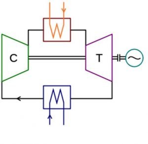
The Brayton Cycle is a closed-loop thermodynamic cycle that consists of four main components: a compressor, a combustion chamber, a turbine, and a heat exchanger. It operates on the principles of the ideal gas law and follows a series of processes to convert thermal energy into mechanical work.

The cycle begins with the compressor, which takes in ambient air and compresses it to a higher pressure. This compressed air then enters the combustion chamber, where fuel is injected and ignited. The resulting high-temperature and high-pressure gases expand, driving the turbine. The turbine extracts energy from the expanding gases, converting it into mechanical work to drive the compressor and any external load, such as an aircraft’s propeller or a power generator.

The exhaust gases from the turbine then pass through a heat exchanger, where they transfer some of their heat to the incoming air before being expelled to the atmosphere. This heat exchange process increases the overall efficiency of the cycle by preheating the air before it enters the combustion chamber.

Diagram of the Brayton Cycle

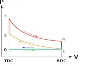
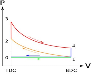
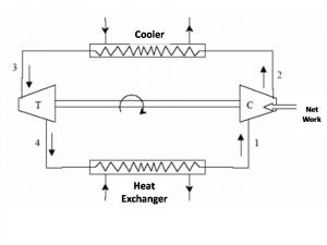
To better understand the Brayton Cycle, let’s take a look at a simplified diagram of the cycle:

Brayton Cycle Diagram

As shown in the diagram, the cycle consists of four main processes:

  1. Process 1-2 (Isentropic Compression): The compressor takes in ambient air at point 1 and compresses it to a higher pressure at point 2. This process is isentropic, meaning there is no heat transfer or change in entropy.

  2. Process 2-3 (Constant Pressure Heat Addition): The compressed air enters the combustion chamber, where fuel is injected and ignited. This process occurs at constant pressure, resulting in a significant increase in temperature.

  3. Process 3-4 (Isentropic Expansion): The high-temperature and high-pressure gases from the combustion chamber expand through the turbine, driving it and producing mechanical work. This expansion process is also isentropic.

  4. Process 4-1 (Constant Pressure Heat Rejection): The exhaust gases from the turbine pass through a heat exchanger, where they transfer some of their heat to the incoming air. This process occurs at constant pressure, reducing the temperature of the exhaust gases before they are expelled to the atmosphere.

P-V and T-S Diagrams of the Brayton Cycle
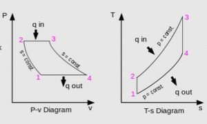
Slide2 1
Wikipedia

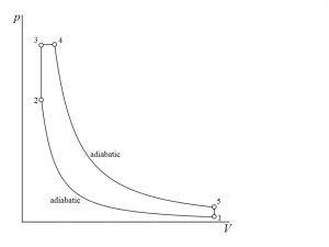
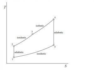
P-V (Pressure-Volume) and T-S (Temperature-Entropy) diagrams are commonly used to visualize the Brayton Cycle. These diagrams provide a graphical representation of the cycle’s processes and help in analyzing its performance.

In the P-V diagram, the vertical axis represents pressure, while the horizontal axis represents volume. The cycle’s processes are represented by lines on the diagram, allowing us to see how pressure and volume change throughout the cycle.

On the other hand, the T-S diagram plots temperature against entropy. It helps us understand the heat transfer and energy exchange that occur during the cycle. The T-S diagram shows the cycle’s processes as curves, allowing us to analyze the changes in temperature and entropy.

Both diagrams provide valuable insights into the performance of the Brayton Cycle, allowing engineers to optimize its efficiency and power output.

In the next sections, we will explore the important relationships within the Brayton Cycle and answer some frequently asked questions about this thermodynamic cycle.

Steps of the Brayton Cycle

The Brayton Cycle is a thermodynamic cycle that is commonly used in gas turbine engines and power generation systems. It consists of four main processes that work together to produce power efficiently. Let’s take a closer look at each step of the Brayton Cycle.

Process 1-2: Reversible Adiabatic Compression

In this first step of the Brayton Cycle, the air is drawn into the compressor, where it is compressed to a higher pressure. The compression process is adiabatic, meaning that no heat is added or removed from the system. As the air is compressed, its temperature increases. This step is crucial as it prepares the air for the subsequent combustion process.

Process 2-3: Constant Pressure Heat Addition

After the air is compressed, it enters the combustion chamber, where fuel is injected and ignited. The high-pressure air from the compressor mixes with the fuel, and combustion occurs. This process is carried out at a constant pressure, allowing for efficient heat transfer from the combustion products to the working fluid. As a result, the temperature and pressure of the working fluid increase significantly.

Process 3-4: Reversible Adiabatic Expansion

Once the air-fuel mixture has undergone combustion and reached its maximum temperature, it enters the turbine. In the turbine, the high-pressure, high-temperature gases expand, driving the turbine blades and producing useful work. The expansion process is adiabatic, meaning that no heat is added or removed from the system. As the gases expand, their temperature and pressure decrease.

Process 4-1: Constant Pressure Heat Rejection

In the final step of the Brayton Cycle, the low-pressure gases from the turbine enter the heat exchanger, where heat is rejected to the surroundings. This process occurs at a constant pressure, allowing for efficient heat transfer. As the gases cool down, their temperature and pressure decrease further, preparing them to re-enter the compressor and start the cycle again.

By following these four processes, the Brayton Cycle can continuously produce power in a gas turbine engine or power generation system. The cycle is highly efficient, as it maximizes the conversion of heat energy into useful work. The thermal efficiency of the Brayton Cycle can be improved by increasing the pressure ratio and temperature ratio, which can be achieved through design modifications and advanced technologies.

In summary, the Brayton Cycle is a fundamental thermodynamic cycle used in gas turbine engines and power generation systems. It consists of four main processes: reversible adiabatic compression, constant pressure heat addition, reversible adiabatic expansion, and constant pressure heat rejection. Each step plays a crucial role in the overall efficiency of the cycle, allowing for the continuous production of power.

Brayton Cycle Refrigeration

Introduction to Brayton Refrigeration Cycle

The Brayton Cycle, also known as the gas turbine cycle, is a thermodynamic cycle that is widely used in power generation, jet engines, and gas turbines. It consists of four main components: compressor, combustion chamber, turbine, and heat exchanger. The cycle operates on the principle of converting thermal energy into mechanical work.

In the context of refrigeration, the Brayton Cycle can be modified to create a refrigeration cycle known as the Brayton Refrigeration Cycle. This cycle utilizes the same components as the traditional Brayton Cycle but with a different configuration. Instead of producing work output, the goal of the Brayton Refrigeration Cycle is to remove heat from a low-temperature reservoir and reject it to a high-temperature reservoir.

The Brayton Refrigeration Cycle is commonly used in cryogenic applications, such as liquefaction of gases and air separation. It offers several advantages over other refrigeration cycles, including high efficiency, compact size, and the ability to achieve very low temperatures.

Inverted Brayton Cycle

The Inverted Brayton Cycle, also known as the Brayton Heat Pump Cycle, is a variation of the traditional Brayton Cycle. In this cycle, the roles of the hot and cold reservoirs are reversed compared to the Brayton Refrigeration Cycle. The goal of the Inverted Brayton Cycle is to absorb heat from a low-temperature reservoir and reject it to a high-temperature reservoir, thus providing heating instead of cooling.

The Inverted Brayton Cycle finds applications in heat pumps, where it can be used for space heating, water heating, and industrial processes. It offers advantages such as high efficiency, low operating costs, and the ability to provide both heating and cooling.

Joule Brayton Cycle

gif 25
Wikipedia

The Joule Brayton Cycle, also known as the simple Brayton Cycle, is the basic form of the Brayton Cycle. It operates on the principle of constant pressure combustion and is commonly used in gas turbine engines. The cycle consists of a compressor, combustion chamber, turbine, and heat exchanger.

In the Joule Brayton Cycle, air is compressed by the compressor, then heated in the combustion chamber where fuel is burned, resulting in a high-temperature, high-pressure gas. This gas expands through the turbine, producing work output, and then passes through the heat exchanger to reject heat to the surroundings. The cycle is then repeated.

The Joule Brayton Cycle is widely used in power generation, where it converts the energy of a fuel into mechanical work to drive a generator. It offers high thermal efficiency and is capable of generating large amounts of power.

Reverse Brayton Cycle

The Reverse Brayton Cycle, also known as the Brayton Cryocooler Cycle, is a modification of the traditional Brayton Cycle that is used for cryogenic cooling applications. In this cycle, the roles of the hot and cold reservoirs are reversed compared to the Brayton Refrigeration Cycle. The goal of the Reverse Brayton Cycle is to absorb heat from a high-temperature reservoir and reject it to a low-temperature reservoir, thus achieving cryogenic temperatures.

The Reverse Brayton Cycle finds applications in cryogenic systems, such as cooling of superconducting magnets, infrared detectors, and medical imaging devices. It offers advantages such as high cooling capacity, compact size, and the ability to achieve very low temperatures.

In conclusion, the Brayton Cycle and its variations play a crucial role in various industries, including power generation, refrigeration, heating, and cryogenics. Each variation of the cycle offers unique advantages and is tailored to specific applications. Understanding the principles and applications of the Brayton Cycle is essential for engineers and researchers working in these fields.

Brayton Cycle vs. Rankine Cycle
Slide1 1
Wikipedia

Comparison of Brayton Cycle and Rankine Cycle

The Brayton Cycle and Rankine Cycle are two thermodynamic cycles commonly used in power generation and propulsion systems. While both cycles involve the conversion of heat into work, they differ in several aspects.

Brayton Cycle Rankine Cycle
Used in gas turbine engines and jet engines Used in steam power plants
Operates on an open cycle Operates on a closed cycle
Uses a compressor, combustion chamber, and turbine Uses a pump, boiler, and turbine
Utilizes a gas as the working fluid Utilizes a liquid (usually water) as the working fluid
Higher thermal efficiency Lower thermal efficiency
Higher power-to-weight ratio Lower power-to-weight ratio

Differences in Heat Addition and Rejection

One of the key differences between the Brayton Cycle and Rankine Cycle lies in the way heat is added and rejected. In the Brayton Cycle, heat addition occurs in the combustion chamber, where fuel is burned, and the resulting high-temperature gases expand through the turbine, producing work. The heat rejection takes place in the heat exchanger, where the exhaust gases transfer their heat to the surroundings.

On the other hand, the Rankine Cycle involves heat addition in the boiler, where the working fluid is heated by the combustion of fuel. The high-pressure liquid then expands through the turbine, generating work. Heat rejection occurs in the condenser, where the working fluid is cooled and condensed back into a liquid state.

Handling of Low-Pressure Gas

Another notable difference between the Brayton Cycle and Rankine Cycle is the handling of low-pressure gas. In the Brayton Cycle, the low-pressure gas is discharged directly into the atmosphere after passing through the turbine. This open cycle allows for continuous operation without the need for a condenser.

In contrast, the Rankine Cycle is a closed cycle, which means the low-pressure liquid is pumped back to the boiler to be reheated and undergo the cycle again. This closed-loop system requires the use of a condenser to cool and condense the working fluid back into a liquid state before it is pumped back to the boiler.

Overall, while both the Brayton Cycle and Rankine Cycle are thermodynamic cycles used for power generation, they differ in terms of their applications, working fluids, heat addition and rejection processes, and handling of low-pressure gas. Understanding these differences is crucial in designing and optimizing power generation systems and propulsion systems for various applications.

Brayton Cycle Explained

The Brayton cycle, also known as the gas turbine cycle, is a thermodynamic cycle used in power generation and jet engines. It consists of four main components: a compressor, a combustion chamber, a turbine, and a heat exchanger. In this section, we will explore the different aspects of the Brayton cycle, including its ideal form, derivation and analysis, regeneration, and modifications for actual applications.

Ideal Brayton Cycle and Thermal Efficiency

gif 11 1
Wikipedia

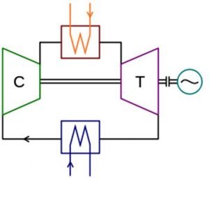
The ideal Brayton cycle is a theoretical model that assumes perfect conditions and no losses. It consists of two reversible adiabatic processes and two isobaric processes. The cycle starts with the compression of air by the compressor, followed by the addition of heat in the combustion chamber. The high-pressure and high-temperature gases then expand through the turbine, producing work output. Finally, the gases are cooled in the heat exchanger before returning to the compressor.

The thermal efficiency of the ideal Brayton cycle can be calculated using the temperature and pressure ratios. The temperature ratio, denoted by T3/T2, represents the ratio of the turbine inlet temperature to the compressor inlet temperature. The pressure ratio, denoted by P3/P2, represents the ratio of the turbine inlet pressure to the compressor inlet pressure. The thermal efficiency, denoted by ηth, is given by the formula:

ηth = 1 – (1 / (P3/P2)((γ-1)/γ))

where γ is the specific heat ratio of the working fluid.

Derivation and Analysis of Brayton Cycle

To derive the Brayton cycle, we consider the first law of thermodynamics and apply it to each component of the cycle. By assuming ideal gas behavior and neglecting kinetic and potential energy changes, we can derive the expressions for work and heat transfer in each process. This allows us to analyze the performance of the cycle and calculate important parameters such as the work output and heat input.

The analysis of the Brayton cycle involves evaluating the net work output, thermal efficiency, and specific work output. These parameters depend on the pressure ratio, temperature ratio, and specific heat ratio of the working fluid. By varying these ratios, we can optimize the cycle for different applications, such as power generation or aircraft propulsion.

Brayton Cycle with Regeneration

gif 21
Wikipedia
Slide1
Wikipedia

Regeneration is a technique used to improve the thermal efficiency of the Brayton cycle. It involves recovering some of the waste heat from the exhaust gases and using it to preheat the compressed air before it enters the combustion chamber. This reduces the amount of fuel required to reach the desired turbine inlet temperature, resulting in higher thermal efficiency.

In a regenerative Brayton cycle, a heat exchanger, known as a regenerator, is placed between the compressor and the combustion chamber. The regenerator transfers heat from the hot exhaust gases to the cold compressed air, increasing its temperature. This preheated air then enters the combustion chamber, where fuel is added and combustion occurs. The rest of the cycle remains the same as the ideal Brayton cycle.

Actual Brayton Cycle and Efficiency Modifications

In real-world applications, the Brayton cycle deviates from the ideal model due to various losses and inefficiencies. These include pressure losses in the compressor and turbine, heat losses to the surroundings, and combustion inefficiencies. To account for these factors, modifications are made to the ideal Brayton cycle to improve its efficiency and performance.

One common modification is the use of intercooling and reheating. Intercooling involves cooling the compressed air between stages of the compressor, reducing its temperature and increasing its density. Reheating, on the other hand, involves adding heat to the gases between stages of the turbine, increasing their temperature and expanding them further. These modifications help to mitigate the effects of irreversibilities and improve the overall efficiency of the cycle.

Another modification is the inclusion of a bypass system, commonly used in aircraft engines. This allows a portion of the compressed air to bypass the combustion chamber and directly mix with the exhaust gases, reducing fuel consumption and increasing thrust.

In conclusion, the Brayton cycle is a fundamental thermodynamic cycle used in gas turbines and jet engines. Understanding its ideal form, derivation, regeneration, and modifications is crucial for optimizing its performance and efficiency in various applications. By continuously improving and refining the Brayton cycle, engineers can enhance power generation, propulsion systems, and other industrial processes.

Frequently Asked Questions (FAQ) about the Brayton Cycle

How to Increase Efficiency of Brayton Cycle

The efficiency of the Brayton cycle, also known as the gas turbine cycle, can be improved by implementing certain measures. Here are some ways to increase the efficiency of the Brayton cycle:

  1. Increasing the Pressure Ratio: The efficiency of the Brayton cycle is directly proportional to the pressure ratio. By increasing the pressure ratio, the cycle can extract more work from the same amount of heat input, resulting in higher efficiency.

  2. Increasing the Temperature Ratio: Similar to the pressure ratio, increasing the temperature ratio also improves the efficiency of the Brayton cycle. This can be achieved by using more efficient combustion techniques or by utilizing advanced materials that can withstand higher temperatures.

  3. Utilizing Regenerative Heating: In a regenerative Brayton cycle, a heat exchanger is used to preheat the compressed air before it enters the combustion chamber. This reduces the amount of heat required in the combustion process, resulting in improved efficiency.

  4. Optimizing the Compressor and Turbine Design: The efficiency of the compressor and turbine plays a crucial role in the overall efficiency of the Brayton cycle. By optimizing the design and using advanced materials, the losses in these components can be minimized, leading to higher efficiency.

Application of Brayton Cycle

The Brayton cycle finds its application in various fields, including power generation and jet engines. Here are some key applications of the Brayton cycle:

  1. Gas Turbines: Gas turbines are widely used in power generation, aviation, and industrial applications. The Brayton cycle forms the basis of gas turbine engines, where the combustion of fuel produces high-temperature gases that drive the turbine, generating power or thrust.

  2. Jet Engines: Jet engines, commonly used in aircraft, also operate on the Brayton cycle. The incoming air is compressed, mixed with fuel, and ignited in the combustion chamber. The resulting high-velocity exhaust gases propel the aircraft forward, providing thrust.

  3. Power Generation: Gas turbine power plants utilize the Brayton cycle to generate electricity. The combustion of fuel in the gas turbine produces high-pressure and high-temperature gases that drive the turbine, which is connected to a generator, converting mechanical energy into electrical energy.

Brayton Cycle Problems and Solutions

gif 28

While the Brayton cycle offers numerous advantages, it also presents some challenges. Here are some common problems encountered in the Brayton cycle and their solutions:

  1. Compressor Surge: Compressor surge occurs when the flow rate through the compressor decreases abruptly, leading to a disruption in the cycle’s operation. To prevent compressor surge, anti-surge control systems are employed, which regulate the flow and maintain stable compressor operation.

  2. Combustion Instability: Combustion instability can cause fluctuations in the flame, leading to reduced efficiency and increased emissions. Advanced combustion techniques, such as lean premixed combustion, are employed to mitigate combustion instability and improve overall performance.

  3. Heat Exchanger Fouling: Fouling of the heat exchanger surfaces can reduce the efficiency of the Brayton cycle. Regular maintenance and cleaning of the heat exchanger surfaces help prevent fouling and ensure optimal heat transfer.

Power Calculation and Compressor Efficiency

Calculating the power output and compressor efficiency is essential to assess the performance of the Brayton cycle. Here’s how these parameters are determined:

  1. Power Calculation: The power output of the Brayton cycle can be calculated using the equation: Power Output = Mass Flow Rate * Specific Work Output. The mass flow rate is the rate at which air passes through the cycle, and the specific work output is the work done by the turbine per unit mass of air.

  2. Compressor Efficiency: Compressor efficiency is a measure of how effectively the compressor compresses the air. It is calculated as the ratio of the actual work done by the compressor to the ideal work done. Compressor efficiency can be improved by optimizing the compressor design and reducing losses.

Comparison of Simple and Regenerative Brayton Cycles

The Brayton cycle can be implemented in two configurations: simple and regenerative. Here’s a comparison between the two:

Parameter Simple Brayton Cycle Regenerative Brayton Cycle
Heat Exchanger Not present Present
Preheating of Compressed Air Not applicable Achieved through a heat exchanger
Efficiency Lower efficiency compared to regenerative cycle Higher efficiency due to preheating of compressed air
Implementation Complexity Simple More complex
Cost Relatively lower cost Higher cost due to the additional heat exchanger

Brayton Cycle in Gas Turbines

Slide3 1
Wikipedia

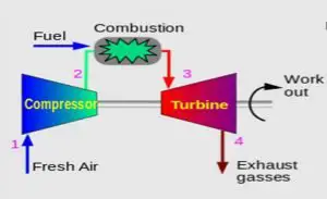
The Brayton cycle forms the basis of gas turbine engines used in power generation and aviation. Here’s how the Brayton cycle is implemented in gas turbines:

  1. Compressor: The incoming air is compressed by the compressor, increasing its pressure and temperature.

  2. Combustion Chamber: The compressed air is mixed with fuel and ignited in the combustion chamber, resulting in the release of high-temperature gases.

  3. Turbine: The high-temperature gases expand through the turbine, driving its blades and extracting work to generate power or thrust.

  4. Exhaust: The exhaust gases, after passing through the turbine, are expelled into the atmosphere, completing the Brayton cycle.

Gas turbines offer high power-to-weight ratios, making them suitable for applications where weight and size are critical factors, such as aircraft propulsion and mobile power generation.

In conclusion, the Brayton cycle, with its various applications and potential for efficiency improvements, plays a vital role in power generation and aviation. Understanding the key concepts, challenges, and solutions related to the Brayton cycle is essential for optimizing its performance and exploring future advancements in this thermodynamic cycle.

Frequently Asked Questions

Q: What is the Brayton cycle?

A: The Brayton cycle, also known as the gas turbine cycle, is a thermodynamic cycle used in power generation and jet engines. It consists of four main components: a compressor, combustion chamber, turbine, and heat exchanger.

Q: What are the steps involved in the Brayton cycle?

A: The Brayton cycle involves four steps: compression, combustion, expansion, and exhaust. During compression, the air is compressed by the compressor. In the combustion step, fuel is added and ignited in the combustion chamber. Expansion occurs as the high-pressure gas passes through the turbine, generating work output. Finally, the exhaust step involves releasing the remaining gas to the environment.

Q: How does the Brayton cycle work in refrigeration?

A: The Brayton cycle can be used in refrigeration systems by reversing the direction of heat transfer. Instead of generating power, the cycle absorbs heat from a low-temperature source and rejects it to a high-temperature sink, providing cooling.

Q: Why is 1 Decembrie not considered in the FAQ terms?

A: The term “why not 1 Decembrie” is not relevant to the topics of Brayton cycle, gas turbine cycle, or power generation. Therefore, it is not included in the FAQ terms.

Q: What is the difference between the Brayton cycle and the Rankine cycle?

A: The Brayton cycle is an open cycle used in gas turbines, while the Rankine cycle is a closed cycle used in steam power plants. The Brayton cycle uses air or gas as the working fluid, while the Rankine cycle uses water or steam.

Q: What are the working principles of the Brayton cycle?

A: The working principles of the Brayton cycle involve compressing the working fluid, adding heat through combustion, expanding the fluid to generate work, and then exhausting the fluid. This cycle enables the conversion of thermal energy into mechanical work.

Q: Can you explain the Brayton cycle in more detail?

A: Certainly! The Brayton cycle starts with the compression of air by a compressor, increasing its pressure and temperature. The compressed air then enters the combustion chamber, where fuel is added and ignited, resulting in a high-temperature gas. This gas expands through the turbine, producing work output. Finally, the exhaust gas is released, and the cycle repeats.

Q: What is the role of gas turbines in the Brayton cycle?

A: Gas turbines are the key components of the Brayton cycle. They consist of a compressor, combustion chamber, and turbine. The compressor compresses the air, the combustion chamber adds fuel and ignites it, and the turbine extracts work from the expanding gas.

Q: How does the pressure ratio affect the Brayton cycle?

A: The pressure ratio, defined as the ratio of the compressor outlet pressure to the inlet pressure, affects the performance of the Brayton cycle. A higher pressure ratio leads to increased thermal efficiency and work output, but it also requires a more robust and efficient compressor.

Q: How is the thermal efficiency of the Brayton cycle calculated?
Slide3
Wikipedia

A: The thermal efficiency of the Brayton cycle is calculated as the ratio of the net work output to the heat input. It can be expressed as the difference between the compressor and turbine work divided by the heat input from the combustion chamber.
Dual Cycle: 11 Important Factors Related To It

CodeCogsEqn 2023 02 03T212139.469

Content : Dual Cycle

What is Dual cycle?

Dual Combustion Cycle | Mixed cycle | Sabathe cycle

The dual cycle is named after The Russian-German engineer Gustav Trikler. It is also known as the mixed cycle, Trinkler cycle, seiliger cycle or sabathe cycle.

Dual cycle is a combination of constant volume Otto cycle and constant pressure diesel cycle. Heat addition takes place in two parts in this cycle. Partial heat addition takes place at constant volume similar to Otto cycle while the remaining Partial heat addition takes place at constant pressure similar to diesel cycle. The significance of such method of heat addition is it gives more time to fuel for complete combustion.

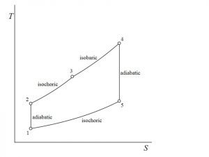
Dual cycle P-V Diagram | Dual cycle T-S Diagram

The dual cycle comprises of following operations:

  • Process 1-2 follows the reversible adiabatic or Isentropic compression
  • In Process 2-3 constant volume partial heat Addition takes place
  • In Process 3-4 constant pressure partial heat Addition takes place
  • Process 4-5 follows reversible adiabatic or isentropic expansion.
  • In Process 5-1 constant volume heat rejection takes place

Dual Cycle efficiency | Dual Cycle Thermal efficiency

The efficiency of dual cycle is given by

\\eta_{dual}=1-\\frac{1}{r_k^{\\gamma -1}}[\\frac{r_pr_c^\\gamma -1}{(r_p-1)+r_p\\gamma (r_c-1)}]

Where, rp = Pressure ratio = P3/P2

rk = compression ratio = V1/V2

rc = cutoff ratio = V4 /V3

re = expansion ratio = V5/V4

When rc = 1, The cycle becomes Otto cycle

rp = 1, the cycle becomes diesel cycle.

Dual cycle P-V and T-S diagram

Air standard dual cycle | Dual cycle efficiency derivation

The dual cycle comprises of following operations:

  • Process 1-2 follows the reversible adiabatic or Isentropic compression
  • In Process 2-3 constant volume partial heat Addition takes place
  • In Process 3-4 constant pressure partial heat Addition takes place
  • Process 4-5 follows reversible adiabatic or isentropic expansion.
  • In Process 5-1 constant volume heat rejection takes place

Total Heat supplied is given by

Q_s=mC_v [T_3-T_2 ]+mC_p [T_4-T_3]

Where Heat supplied at constant volume

Q_v= mC_v [T_3-T_2 ]

Where Heat supplied at constant pressure

Q_p= mC_p [T_4-T_3]

Heat rejected at constant volume is given by

Q_r= mC_v [T_5-T_1 ]

The efficiency of dual cycle is given by

\\eta=\\frac{(mC_v [T_3-T_2 ]+mC_p [T_4-T_3 ]-mC_v [T_5-T_1 ])}{(mC_v [T_3-T_2 ]+mC_p [T_4-T_3])}

\\\\\\eta=1-\\frac{(T_5-T_1)}{([T_3-T_2 ]+\\gamma[T_4-T_3])}\\\\\\\\ \\eta_{dual}=1-\\frac{1}{r_k^{\\gamma -1}}[\\frac{r_pr_c^\\gamma -1}{(r_p-1)+r_p\\gamma (r_c-1)}]

Where, rp = Pressure ratio = P3/P2

rk = compression ratio = V1/V2                 

rc = cutoff ratio = V4 /V3

re = expansion ratio = V5/V4

When rc = 1, the cycle becomes Otto cycle

rp = 1, the cycle becomes diesel cycle.

Mean effective pressure of dual cycle

The mean effective pressure of dual cycle is given by

M.E.P=\\frac{(P_1 [\\gamma r_p r_k^\\gamma (r_c-1)+r_k^\\gamma (r_p-1)-r_k (r_p r_c^\\gamma-1) ] )}{(\\gamma-1)(r_k-1) }

Where, rp = Pressure ratio = P3/P2

rk = compression ratio = V1/V2

rc = cutoff ratio = V4 /V3

re = expansion ratio = V5/V4

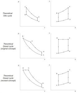
Otto Diesel Dual Cycle Diagram

Otto Diesel Duel cycle
Image Credit: Wikipedia Commons

Comparison between Otto, diesel and dual cycle

Case 1: For similar compression ratio and similar heat i/p this relationship will be

[Qin]otto = [Qin]Diesel.

[QR]otto< [QR]Diesel.

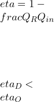
\\\\\\eta=1-\\frac{Q_R}{Q_{in}}\\\\\\\\ \\eta_D<\\eta_O

In this case of same compression ratio and equal heat input it will be

\\eta_D<\\eta_{dual}<\\eta_O

Case 2: In this case of, same compression ratio and same heat-rejection, this relationship will be

[Qin]otto> [Qin]Diesel.

[QR]otto= [QR]Diesel.

\\\\\\eta=1-\\frac{Q_R}{Q_{in}}\\\\\\\\ \\eta_D<\\eta_O

In this case of, same compression ratio and same heat-rejection.

\\eta_D<\\eta_{dual}<\\eta_O

Case 3: In this case of, same Maximum Temperature and same heat-rejection.

[QR]otto= [QR]Diesel

[Qin]Diesel>[Qin]otto

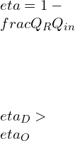
\\\\\\eta=1-\\frac{Q_R}{Q_{in}}\\\\\\\\ \\eta_D>\\eta_O

For same Maximum Temperature and same heat rejection

\\eta_D>\\eta_{dual}>\\eta_O

Dual fuel engine cycle | Mixed dual cycle

Dual Cycle Engine

Dual fuel engine works primarily on diesel cycle. The gaseous fuel [Natural gas] is introduced into the engine’s intake system through a supercharger at higher atmospheric pressure.

During the suction stroke, the leaner air-to-fuel ratio [air-to-natural gas mixture] is drawn into the cylinder, following the Otto cycle just as used in a spark-ignited engine. A small charge of pilot fuel is injected near the Top Dead Center and similar to CI engine it ignites near the end of the compression stroke, causing the secondary gas to burn. The combustion takes place smoothly and rapidly.

In dual-fuel engine pilot fuel and secondary fuel both burn simultaneously in a compression ignition engine. After the compression of secondary fuel at the suction stroke pilot fuel is used as a source of ignition.

The operating cost of this engine is lower than that of conventional diesel engine without compromising in delivery power, high torque and transient response.

Dual cycle application

  • Dual cycle is widely used for small propulsion engines and portable heavy duty machinery like drilling machines by companies like Cummins etc. The major reason of dual cycle being used in mobile equipment’s is it provides high power to mass ratio in comparison with Otto and diesel cycle.
  • They have wide range of application in aircraft and ships. Dual cycle engine are also called marine engine.

Advantage of dual cycle

  1. Higher heat yield – methane has the highest thermal output per unit mass of fuel, at 50,500kJ/kg methane burned compared to 44,390kJ heat/kg petrol burned or 43,896kJ heat/kg diesel burned. Many dual-combustion engines use natural gas whose primary content is methane as starter fuels because of its higher heat output.
  2. With a dual fuel combustion engine, two fuels must be purchased instead of one. This can help when the ship is low on both fuels, and the re-fueling location lacks one of the two fuels the engine takes in.
  3. A potential balance between clean fuel and economical storage – natural gas needs higher storage pressure and volume but offers better combustion efficiency. Diesel is easier to store (it’s a liquid oil) but does not burn as quickly for the same temperature and pressure as the other fuels. With a dual combustion engine, one can start the diesel engine then switch to natural gas when the combustion space is hot enough.

Dual Cycle problems and solutions

A C.I engine has a compression ratio of 10. The heat liberated at constant volume is 2/3 of total Heat while the remaining is liberated at constant pressure. The initial pressure and temperature is 1 bar and 27oC. Maximum cycle pressure is 40 bars. Find temperature at the end of compression and expansion. [PV1.35 = C, ϒ = 1.4]

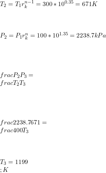
Solution: rk = 10, P1 = 1 bar = 100 kPa, T1=27 C = 300K, P3 = P4 = 40 bar, PV1.35 = C, ϒ = 1.4

\\\\T_2=T_1 r_k^{n-1}=300*10^{0.35}=671 K\\\\\\\\ P_2=P_1 r_k^n=100*10^{1.35}=2238.7 kPa\\\\\\\\ \\frac{P_2}{P_3}=\\frac{T_2}{T_3}\\\\\\\\ \\frac{2238.7}{671}=\\frac{400}{T_3}\\\\\\\\ T_3=1199\\;K

Heat input at constant volume

\\\\Q_v=C_v [T_3-T_2 ]=0.718*[1199-671]=379kJ/kg\\\\\\\\ (2/3)*Q=Q_v\\\\\\\\ Q=(3/2)*379=568.5 kJ/kg\\\\\\\\ C_p [T_4-T_3 ]=Q/3\\\\\\\\ 1.005*[T_4-1199]=568.5/3\\\\\\\\ T_4=1387.55 K

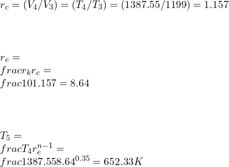
\\\\r_c=(V_4/V_3) =(T_4/T_3) =(1387.55/1199)=1.157\\\\\\\\ r_e=\\frac{r_k}{r_c} =\\frac{10}{1.157}=8.64\\\\\\\\ T_5=\\frac{T_4}{r_e^{n-1}} =\\frac{1387.55}{8.64^{0.35}} =652.33 K

An air standard dual cycle before compression air is at 100 kPa and 300K. During compression the volume changes from 0.07 m3 to 0.004m3. For constant pressure heat addition, the temperature varies from 1160 C to 1600C. Find the compression ratio; mean effective pressure and cut-off ratio for the cycle.

P1 = 100 kPa, T1=27 C = 300K

Compression ratio

r_k=[V_1/V_2] =[0.07/0.004]=17.5

T3 = 1160C = 1433 K, T4 = 1600 C = 1873 K

For isentropic compression process

\\\\P_1 V_1^\\gamma=P_2 V_2^\\gamma\\\\\\\\ P_2=P_1 r_k^{\\gamma}=100*17.5^{1.4}=5498.6 kPa\\\\\\\\ \\frac{T_2}{T_1}=r_k^{\\gamma -1}\\\\\\\\ T_2=300*17.5^{1.4-1}=942.6 K

Cut-off ratio

\\\\r_c=[T_4/T_3 ]=[1873/1433]=1.307\\\\\\\\ Also \\;\\\\\\\\ r_c=[V_4/V_3] =1.307\\\\\\\\ V_4=1.307*0.004=5.228*10^{-3} m^3

For isentropic expansion process

\\\\T_5/T_4 =[V_4/V_5] ^{\\gamma-1}\\\\\\\\ (T_5/1873)=[\\frac{(5.228*10^{-3})}{0.07}]^{1.4-1}\\\\\\\\ T_5=663.48 K

Total Heat Supplied

\\\\Q_s=C_v [T_3-T_2 ]+C_p [T_4-T_3 ]\\\\\\\\ Q_s=0.717*(1433-942.6)+1.005*(1873-1433)\\\\\\\\ Q_s=793.81 kJ

Heat rejected

\\\\Q_r=C_v (T_5-T_1)\\\\\\\\ Q_r=0.717*(663.45-300)=260.6 kJ

Work done is given by

W=Q_s-Q_r = 793.81-260.6 = 533.21 kJ

Mean effective pressure for dual cycle

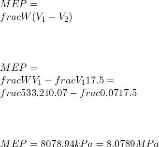
\\\\MEP=\\frac{W}{(V_1-V_2 )}\\\\\\\\ MEP=\\frac{W}{V_1-\\frac{V_1}{17.5}}=\\frac{533.21}{0.07-\\frac{0.07}{17.5}}\\\\\\\\ MEP=8078.94 kPa=8.0789 MPa

FAQ

Q.1) where is dual cycle used?

Ans: – Dual cycle is widely used for small propulsion engines and portable heavy duty machinery like drilling machines by companies like Cummins etc. The major reason of dual cycle being used in mobile equipments is it provides high power to mass ratio in comparison with Otto and diesel cycle.

They have wide range of application in aircraft and ships. Dual cycle engine are also called marine engine.

Q.2) what is the efficiency of dual cycle?

The efficiency of dual cycle is given by

\\eta_{dual}=1-\\frac{1}{r_k^{\\gamma -1}}[\\frac{r_pr_c^\\gamma -1}{(r_p-1)+r_p\\gamma (r_c-1)}]

Where, rp = Pressure ratio = P3/P2

rk = compression ratio = V1/V2

rc = cutoff ratio = V4 /V3

re = expansion ratio = V5/V4

When rc = 1, The cycle becomes Otto cycle

rp = 1, the cycle becomes diesel cycle.

Q.3) what are the importance of dual cycle in the diesel engine operations?

Dual fuel engine works primarily on diesel cycle. The gaseous fuel [Natural gas] is introduced into the engine’s intake system through a supercharger at higher atmospheric pressure.

During the suction stroke, the leaner air-to-fuel ratio [air-to-natural gas mixture] is drawn into the cylinder, following the Otto cycle just as used in a spark-ignited engine. A small charge of pilot fuel is injected near the Top Dead Center and similar to CI engine it ignites near the end of the compression stroke, causing the secondary gas to burn. The combustion takes place smoothly and rapidly.

In dual-fuel engine pilot fuel and secondary fuel both burn simultaneously in a compression ignition engine. After the compression of secondary fuel at the suction stroke pilot fuel is used as a source of ignition.

The operating cost of this engine is lower than that of conventional diesel engine without compromising in delivery power, high torque and transient response.

Q.4) why is the dual cycle known as a mixed cycle?

Dual fuel engine works primarily on diesel cycle. The gaseous fuel [Natural gas] is introduced into the engine’s intake system through a supercharger at higher atmospheric pressure.

During the suction stroke, the leaner air-to-fuel ratio [air-to-natural gas mixture] is drawn into the cylinder, following the Otto cycle just as used in a spark-ignited engine. A small charge of pilot fuel is injected near the Top Dead Center and similar to CI engine it ignites near the end of the compression stroke, causing the secondary gas to burn. The combustion takes place smoothly and rapidly.

In dual-fuel engine pilot fuel and secondary fuel both burn simultaneously in a compression ignition engine. After the compression of secondary fuel at the suction stroke pilot fuel is used as a source of ignition.

The operating cost of this engine is lower than that of conventional diesel engine without compromising in delivery power, high torque and transient response.

Q.5) what is cut off ratio in dual cycle?

The cut-off ratio for dual cycle is given by

rc = cutoff ratio = V4 /V3

Where, V4 = volume after partial heat addition at constant pressure

V3 = volume after partial heat addition at constant volume

Q.6) What is Dual cycle P-V and T-S diagram ?

To see the answer Click here

Q.7) Dual cycle solved example.

A C.I engine has a compression ratio of 10. The heat liberated at constant volume is 2/3 of total Heat while the remaining is liberated at constant pressure. The initial pressure and temperature is 1 bar and 27oC. Maximum cycle pressure is 40 bars. Find temperature at the end of compression and expansion. [PV1.35 = C, ϒ = 1.4]

Solution: rk = 10, P1 = 1 bar = 100 kPa, T1=27 C = 300K, P3 = P4 = 40 bar, PV1.35 = C, ϒ = 1.4

\\\\T_2=T_1 r_k^{n-1}=300*10^{0.35}=671 K\\\\\\\\ P_2=P_1 r_k^n=100*10^{1.35}=2238.7 kPa\\\\\\\\ \\frac{P_2}{P_3}=\\frac{T_2}{T_3}\\\\\\\\ \\frac{2238.7}{671}=\\frac{400}{T_3}\\\\\\\\ T_3=1199\\;K

Heat input at constant volume

\\\\Q_v=C_v [T_3-T_2 ]=0.718*[1199-671]=379kJ/kg\\\\\\\\ (2/3)*Q=Q_v\\\\\\\\ Q=(3/2)*379=568.5 kJ/kg\\\\\\\\ C_p [T_4-T_3 ]=Q/3\\\\\\\\ 1.005*[T_4-1199]=568.5/3\\\\\\\\ T_4=1387.55 K

\\\\r_c=(V_4/V_3) =(T_4/T_3) =(1387.55/1199)=1.157\\\\\\\\ r_e=\\frac{r_k}{r_c} =\\frac{10}{1.157}=8.64\\\\\\\\ T_5=\\frac{T_4}{r_e^{n-1}} =\\frac{1387.55}{8.64^{0.35}} =652.33 K

An air standard dual cycle before compression air is at 100 kPa and 300K. During compression the volume changes from 0.07 m3 to 0.004m3. For constant pressure heat addition, the temperature varies from 1160 C to 1600C. Find the compression ratio; mean effective pressure and cut-off ratio for the cycle.

P1 = 100 kPa, T1=27 C = 300K

Compression ratio

r_k=[V_1/V_2] =[0.07/0.004]=17.5

T3 = 1160C = 1433 K, T4 = 1600 C = 1873 K

For isentropic compression process

\\\\P_1 V_1^\\gamma=P_2 V_2^\\gamma\\\\\\\\ P_2=P_1 r_k^{\\gamma}=100*17.5^{1.4}=5498.6 kPa\\\\\\\\ \\frac{T_2}{T_1}=r_k^{\\gamma -1}\\\\\\\\ T_2=300*17.5^{1.4-1}=942.6 K

Cut-off ratio

\\\\r_c=[T_4/T_3 ]=[1873/1433]=1.307\\\\\\\\ Also \\;\\\\\\\\ r_c=[V_4/V_3] =1.307\\\\\\\\ V_4=1.307*0.004=5.228*10^{-3} m^3

For isentropic expansion process

\\\\T_5/T_4 =[V_4/V_5] ^{\\gamma-1}\\\\\\\\ (T_5/1873)=[\\frac{(5.228*10^{-3})}{0.07}]^{1.4-1}\\\\\\\\ T_5=663.48 K

Total Heat Supplied

\\\\Q_s=C_v [T_3-T_2 ]+C_p [T_4-T_3 ]\\\\\\\\ Q_s=0.717*(1433-942.6)+1.005*(1873-1433)\\\\\\\\ Q_s=793.81 kJ

Heat rejected

\\\\Q_r=C_v (T_5-T_1)\\\\\\\\ Q_r=0.717*(663.45-300)=260.6 kJ

Work done is given by

W=Q_s-Q_r = 793.81-260.6 = 533.21 kJ

Mean effective pressure for dual cycle

\\\\MEP=\\frac{W}{(V_1-V_2 )}\\\\\\\\ MEP=\\frac{W}{V_1-\\frac{V_1}{17.5}}=\\frac{533.21}{0.07-\\frac{0.07}{17.5}}\\\\\\\\ MEP=8078.94 kPa=8.0789 MPa

To know about Polytropic Process (click here)and Prandtl Number (Click here)

Otto Cycle | Its Important Relations and Formulas

Slide1 300x225 1

The Otto Cycle, fundamental to gasoline engines, consists of four strokes: intake, compression, power, and exhaust. It achieves thermal efficiency up to 25-30%. The compression ratio, typically between 8:1 and 12:1, directly influences efficiency and power output.

Otto Cycle Definition

“An Otto cycle is an ideal thermodynamic cycle that explains the working of a typical spark ignition piston engine and this cycle specifically explains, what happens if mass of gas is subjected to changes due to pressure, temp, volume, heat input, and release of heat.”

The Otto cycle engine | Valve timing diagram

  1. Inlet valve opens at 5-100 before the Top Dead Center. This is to ensure that the inlet should open fully when piston reaches at TDC and fresh charge start entering to cylinder as early as possible after TDC.
  2. Suction valve close at 20 – 300 after Bottom dead center BDC to take the advantage of momentum of moving gases.
  3. The spark takes place 30 – 400 before TDC. This is to allow time delay between spark and completion of combustion.
  4. Pressure at the end of power stroke is above atmospheric which increases the work to expel the exhaust gases. So exhaust valve opens at 20 – 300 before BDC so that at BDC pressure reduces to atmospheric pressure and useful work can be saved.
  5. The exhaust valve closes at 15 – 200 after TDC so that inertia of exhaust gas has a tendency to to scavenge the cylinder which will increase volumetric efficiency.

Otto cycle efficiency | thermal efficiency of Otto Cycle Formula

The efficiency of Otto cycle is specified by

\\eta =1-\\frac{1}{r^{\\gamma-1}}

Where r = compression ratio.

Otto Cycle diagram

Otto cycle P-V diagram | Otto cycle T-S diagram

Otto cycle PV diagram
P-V diagram
Otto cycle TS diagram
T-S diagram

Otto, Diesel and Dual cycle | Comparison

Case 1: For similar compression ratio and similar heat i/p this relationship will be

[Qin]otto = [Qin]Diesel.

[QR]otto< [QR]Diesel.

\\\\\\eta=1-\\frac{Q_R}{Q_{in}}\\\\\\\\ \\eta_D<\\eta_O

In this case of same compression ratio and equal heat input it will be

\\eta_D<\\eta_{dual}<\\eta_O

Case 2: In this case of, same compression ratio and same heat-rejection, this relationship will be

[Qin]otto> [Qin]Diesel.

[QR]otto= [QR]Diesel.

\\\\\\eta=1-\\frac{Q_R}{Q_{in}}\\\\\\\\ \\eta_D<\\eta_O

In this case of, same compression ratio and same heat-rejection.

\\eta_D<\\eta_{dual}<\\eta_O

Case 3: In this case of, same Maximum Temperature and same heat-rejection.

[QR]otto= [QR]Diesel

[Qin]Diesel>[Qin]otto

\\\\\\eta=1-\\frac{Q_R}{Q_{in}}\\\\\\\\ \\eta_D>\\eta_O

For same Maximum Temperature and same heat rejection

\\eta_D>\\eta_{dual}>\\eta_O

Compression ratio of Otto cycle

Compression ratio of Otto cycle is defined as the ratio of volume before expansion to volume after expansion

r=\\frac{V_s+V_c}{V_s}=\\frac{V_1}{V_2}

Where Vs = Swept volume of cylinder

Vc = Clearance volume of the cylinder

In this cycle Compression ratio is generally 6 – 10. It is limited to 10 because of knocking in the engine.

Mean effective pressure formula for Otto cycle

Usually Pressure inside the cylinder on an IC engine is continuously changing; mean effective pressure is an imaginary pressure which is assumed to be constant throughout the process.

P_m=\\frac{P_1 r(r_p-1)(r^{\\gamma-1}-1)}{(\\gamma-1)(r-1)}

Where rp = Pressure ratio = P3/P2 = P4/P1

Otto cycle analysis | Otto cycle calculations | Otto cycle efficiency derivation

 Consider an air standard Otto cycle with initial Pressure, Volume and temperature as P1, V1, T1 respectively.

Otto cycle PV diagram
Otto cycle TS diagram
T-S diagram

Process 1-2: Reversible adiabatic compression.

\\frac{T_2}{T_1}=[\\frac{V_1}{V_2}]^{\\gamma-1}

Where,

r is the compression ratio.

Process 2 -3: Heat addition at constant Volume is calculated as,

Qin = m Cv [T­3-T2].

Process 3-4: Reversible adiabatic expansion is calculated as

\\frac{T_3}{T_4}=[\\frac{V_4}{V_3}]^{\\gamma-1}=r^{\\gamma-1}

Process 4 -1: Heat-rejection at constant Volume will be

QR = m Cv [T­4-T1]

Work done = Qin – QR.

Efficiency of the Otto cycle is represented as.

\\eta=1-\\frac{Q_R}{Q_{in}}

\\\\\\eta=1-\\frac{[T_4-T_1]}{[T_3-T_2]}\\\\\\\\ \\frac{T_2}{T_1}=\\frac{T_3}{T_4}\\\\\\\\ \\frac{T_4}{T_1}=\\frac{T_3}{T_2}\\\\\\\\ \\eta=1-\\frac{1}{r^{\\gamma-1}}

Where r = compression ratio.

Working of Two stroke Engine

Two strokes’ engines work on both Otto cycle as well as diesel cycle.

Atkinson cycle vs Otto cycle

Atkinson CycleOtto cycle
Atkinson cycle uses slightly different valve timing diagram. The Inlet valve remains open till the start of compression strokeInlet valve opens at 5-100 before the Top Dead Center. This is to ensure that the inlet should open fully when piston reaches at TDC and fresh charge start entering to cylinder as early as possible after TDC.
Provides higher fuel economy as compared to Otto cycle.Provides Lower fuel economy as compared to Atkinson cycle.
Provides Lower peak power as compared to Otto cycle.Provides higherPeak power as compared to Atkinson cycle.
Mostly used in Hybrid vehicles where electric motor compensates the power deficiency.Mostly used in 4-stroke and 2 – stroke SI engine where higher power is required
dual
Dual Cycle P-V diagram

Brayton cycle vs Otto cycle

Brayton CycleOtto cycle
Constant Pressure Heat addition and heat rejection takes place in Brayton cycle.Constant volume Heat addition and heat rejection takes place in Otto cycle.
It has capabilities to handle large volume of low-pressure gas.Not capable of handling large volume of low-pressure gas due to restriction in reciprocating engine space.
High temperature is experienced throughout the steady state flow process.High temperature is experienced by the engine only during Power stroke.
Suitable for gas turbineSuitable for IC and SI engine.

Advantages and Disadvantages of Otto cycle engine

Advantages:

  • This cycle has more thermal efficiency in comparison to diesel and dual cycle for identical compression ratio and equal heat input rate and same compression ratio and same heat rejection.
  • This cycle engine required less maintenance and are simple and light-weight in design.
  • For complete combustion pollutant emissions are low for Otto engines.

Disadvantages:

  • Has lower compression ratio thus it is Poor at moving heavy loads at low speed.
  • Will not be able to withstand higher stresses and strains as compared with diesel engine

Example of Otto cycle | Otto cycle problems

Q.1] A spark Ignition engine designed to have a compression ratio of 10. This is operating at low temperature and pressure at value 2000C and 200 kilopascals respectively. If Work O/P is 1000 kilo-Joule/kg, compute maximum possible efficiency and mean effective pressure.

Efficiency of this cycle is given by

\\eta =1-\\frac{1}{r^{\\gamma-1}}

Where r = compression ratio = 10

\\eta =1-\\frac{1}{10^{1.4-1}}=0.602=60.2\\%

For compression process

\\frac{T_2}{T_1}=r^{\\gamma-1}

\\frac{T_2}{473}=10^{1.4-1}

T_2=1188 \\;K

For expansion process, we can assume that

\\frac{T_3}{T_4}=r^{\\gamma-1}

\\frac{T_3}{T_4}=10^{1.4-1}

T_3=2.512T_4

Net work done can be computed by the formula

W=C_v [T_3-T_2 ]-C_v [T_4-T_1]

\\\\1000=0.717*[473-1188+T_3-T_4]\\\\\\\\ 1000=0.717*[473-1188+2.512 T_4-T_4]\\\\\\\\ T_4=1395 K

T_3=2.512*1395=3505 K

According to ideal gas theory, we know

P1v1 = RT1

v1=(RT1)/(P1)=(0.287*473)/200=0.6788 m3/kg

mep=\\frac{W}{v_1-v_2}=\\frac{1000}{0.6788-\\frac{0.6788}{10}}=1636.87\\;kPa

Q.2] what will be the effect on the efficiency of an Otto cycle having a compression ratio 6, if Cv increases by 20%. For the purpose of calculation Assume, that  Cv is 0.718 kJ/kg.K.

\\\\\\frac{\\mathrm{d} C_v}{C_v}=0.02\\\\\\\\ \\eta=1-\\frac{1}{r^{\\gamma -1}}=1-\\frac{1}{6^{1.4 -1}}=0.511\\\\\\\\ \\gamma -1=\\frac{R}{C_v}\\\\\\\\ \\eta=1-[\\frac{1}{r}]^\\frac{R}{C_v}

Taking log on both sides

ln(1-\\eta)=\\frac{R}{C_v} ln\\frac{1}{r}

Differentiating both sides

\\\\\\frac{d\\eta}{1-\\eta}=\\frac{-R}{C_v^2}*dC_v*ln[1/r]\\\\\\\\ \\frac{d\\eta}{1-\\eta}=\\frac{-R}{C_v}*\\frac{dC_v}{C_v}*ln[1/r]\\\\\\\\ \\frac{d\\eta}{\\eta}=\\frac{1-\\eta}{\\eta}*\\frac{-R}{C_v}*\\frac{dC_v}{C_v}*ln[1/r]\\\\\\\\ \\frac{d\\eta}{\\eta}=\\frac{1-0.511}{0.511}*\\frac{-0.287}{0.718}*0.02*ln[1/6]\\\\\\\\ \\frac{d\\eta}{\\eta}=-0.0136\\\\\\\\ \\frac{d\\eta}{\\eta}*100=-0.0136*100=-1.36\\%

I.e. If Cv increases by 2% then η decrease by 1.36%.

Frequently Asked Questions

What is the difference between Otto and Diesel cycle?

In Otto cycle heat addition takes place at constant volume while in diesel cycle, heat addition at constant pressure takes place and  Otto-cycle has lower compression ratio below 12 while, diesel cycle has higher compression ratio up to 22.  Otto-cycle uses spark plug for ignition while diesel cycle needs no assistance for ignition. Otto-cycle has lower efficiency as compared to diesel cycle.

Which fuel is used in Otto cycle ? | What is 4-stroke fuel?

Generally Petrol or gasoline mixed with 3-5% ethanol is used in Otto engine. In air standard Otto-cycle, air is assumed to be as a fuel.

Which is more efficient Otto or Diesel cycle?

The normal range of compression ratio for diesel cycle is 16-20 while in Otto-cycle compression ratio is 6 – 10 and due to higher compression ratio used in diesel cycle, the efficiency of diesel cycle is greater than Otto-cycle.

How does Otto cycle works?

  1. Inlet valve opens at 5-100 before the Top Dead Center. This is to ensure that the inlet should open fully when piston reaches at TDC and fresh charge start entering to cylinder as early as possible after TDC.
  2. Suction valve close at 20 – 300 after Bottom dead center BDC to take the advantage of momentum of moving gases.
  3. The spark takes place 30 – 400 before TDC. This is to allow time delay between spark and completion of combustion.
  4. Pressure at the end of power stroke is above atmospheric which increases the work to expel the exhaust gases. So exhaust valve opens at 20 – 300 before BDC so that at BDC pressure reduces to atmospheric pressure and useful work can be saved.
  5. The exhaust valve closes at 15 – 200 after TDC so that inertia of exhaust gases tends to scavenge the cylinder which will increase volumetric efficiency.

Process 1-2: Reversible adiabatic compression

\\frac{T_2}{T_1}=[\\frac{V_1}{V_2}]^{\\gamma-1}=r^{\\gamma-1}

Where r = compression ratio

Process 2 -3: Heat additions at constant Volume

Qin = m Cv [T­3-T2]

Process 3-4: Reversible adiabatic expansion

\\frac{T_3}{T_4}=[\\frac{V_4}{V_3}]^{\\gamma-1}=r^{\\gamma-1}

Process 4 -1: Heat-rejection at constant Volume will be

QR = m Cv [T­4-T1]

Work done = Qin – QR.

Efficiency of the Otto-cycle is represented as.

\\eta=1-\\frac{Q_R}{Q_{in}}

\\\\\\eta=1-\\frac{[T_4-T_1]}{[T_3-T_2]}\\\\\\\\ \\frac{T_2}{T_1}=\\frac{T_3}{T_4}\\\\\\\\ \\frac{T_4}{T_1}=\\frac{T_3}{T_2}\\\\\\\\ \\eta=1-\\frac{1}{r^{\\gamma-1}}

Where r = compression ratio.

Difference between Otto cycle Diesel cycle and Dual cycle

Otto cycle vs Dual cycle

dvs 2

Otto cycle vs Carnot cycle

Carnot CycleOtto cycleIt consists of two reversible isothermal process and two reversible adiabatic processes.Ideal air standard Otto-cycle consists of two Isochoric process and two reversible adiabatic processes.
 It is a hypothetical cycle and is not practically possible to construct.It is a real cycle and is the basis of working of modern Spark ignition engine.
It serves as a yardstick to measure the performance of other engine cycles.It does not serve as a yardstick to measure the performance of other engine cycles.
It has 100% efficiency.It has overall thermal efficiency in the range of 50 – 70 %.
It can be reversed to obtain Carnot refrigeration / heat pump with maximum coefficient of performance.It is a non-reversible cycle.

Otto cycle vs Atkinson cycle

Atkinson CycleOtto cycle
Atkinson cycle uses slightly different valve timing diagram. The Inlet valve remains open till the start of compression strokeInlet valve opens at 5-100 before the Top Dead Center. This is to ensure that the inlet should open fully when piston reaches at TDC and fresh charge start entering to cylinder as early as possible after TDC.
Provides higher fuel economy as compared to Otto-cycle.Provides Lower fuel economy as compared to Atkinson cycle.
Provides Lower peak power as compared to Otto- cycle.Provides higher Peak power as compared to Atkinson cycle.
Mostly used in Hybrid vehicles where electric motor compensates the power deficiency.Mostly used in 4-stroke and 2 – stroke SI engine where higher power is required

Otto cycle formula

The efficiency of Otto-cycle is given by the equation

\\eta =1-\\frac{1}{r^{\\gamma-1}}

Where r = compression ratio = 10

Otto cycle with polytropic process example

An SI engine has a compression ratio 8 while operating with low temperature of 3000C and a low pressure of 250 kPa. If Work o/p is 1000 kilo-Joule/kg, then compute highest efficiency. The compression and expansion takes place polytropically with polytropic index (n = 1.33).

Solution: The efficiency of Otto- cycle is given by the equation

\\eta =1-\\frac{1}{r^{\\gamma-1}}

Here γ = n

\\eta =1-\\frac{1}{r^{n-1}}=1-\\frac{1}{8^{1.33-1}}=49.65\\%

Why the Otto cycle is known as a constant volume cycle?

For this cycle, heat-addition and rejection happens at the fixed volume and the amount of work done is proportionate on heat addition and heat rejection rate, because of this reason Otto-cycle is termed as constant volume cycle.

What are the limitations of the Otto cycle?

  • It has lower compression ratio thus it is Poor at moving heavy loads at low speed.
  • Cannot withstand higher stresses and strains as compared with diesel engine.
  • Overall fuel efficiency is lower than diesel cycle.

Are two stroke engines considered to be Otto cycle engines?

Two strokes engines work on both Otto-cycle as well as diesel cycle. The working of 2-stroke engine is given below:

  1. Piston moves down and useful power is obtained. The downward motion of piston compresses the fresh charge stored in crankcase.
  2. Near the end of expansion stroke, the piston will reveal the exhaust-port at first. Then the cylinder pressure will drop to atmospheric pressure as during that time combustion materialwill leave from the cylinder.
  3. Further motion of piston reveals the transfer port allowing the slightly compressed charge in crank case to be entered the engine’s cylinder.
  4. Projection in piston prevents the fresh charge from passdirectly to the exhaust port and scavenging the combustion materials.
  5. When piston move up from bottom dead centre to top dead center and the transfer port closes at first then exhausts port will close and compression will happen. At the same time vacuum is created in crankcase and fresh charge enter into crankcase for next cycle.

Why is the Atkinson cycle more efficient even though it produces lower compression and pressure than the Otto cycle?

In Atkinson cycle, for isentropic expansion process in Otto cycle is further allowed to proceed and extend to lower cycle pressure in order to increase the work output and we know that efficiency increases for increase in work produced. That is, why the Atkinson cycle is more efficient even though it produces lower compression and pressure than the Otto cycle.

What is the compression ratio of the Otto cycle

Compression ratio of this cycle is elaborated  as

r=\\frac{V_s+V_c}{V_s}=\\frac{V_1}{V_2}

Where,

Vs = Swept volume of cylinder.

Vc = Clearance volume of the cylinder.

Generally in Otto cycle compression ratio is 6 – 10. It is limited to 10 because of knocking in the engine.

Otto cycle vs diesel cycle efficiency

The normal range of compression ratio for diesel cycle is 16-20 while in Otto cycle compression ratio is 6 – 10 and for more compression ratio used in diesel cycle, the efficiency of diesel cycle is greater than Otto cycle.

Case 1: For same compression ratio and exactly identical heat input, the relationship will be

[Qin]otto = [Qin]Diesel.

[QR]otto< [QR]Diesel.

\\\\\\eta=1-\\frac{Q_R}{Q_{in}}\\\\\\\\ \\eta_D<\\eta_O

In this case of same compression ratio and equal heat input it will be

\\eta_D<\\eta_{dual}<\\eta_O

Case 2: In this case of, same compression ratio and same heat-rejection, this relationship will be

[Qin]otto> [Qin]Diesel.

[QR]otto= [QR]Diesel.

\\\\\\eta=1-\\frac{Q_R}{Q_{in}}\\\\\\\\ \\eta_D<\\eta_O

In this case of, same compression ratio and same heat-rejection.

\\eta_D<\\eta_{dual}<\\eta_O

Case 3: In this case of, same Maximum Temperature and same heat-rejection.

[QR]otto= [QR]Diesel

[Qin]Diesel>[Qin]otto

\\\\\\eta=1-\\frac{Q_R}{Q_{in}}\\\\\\\\ \\eta_D>\\eta_O

For same Maximum Temperature and same heat rejection

\\eta_D>\\eta_{dual}>\\eta_O

Under which condition the efficiency of Brayton cycle and Otto cycle are going to be equal.

The efficiency of Otto cycle is given by the equation

Solution: The efficiency of Otto cycle is given by the equation

\\eta_o =1-\\frac{1}{r^{\\gamma-1}}

r = compression ratio = V1/V2

The efficiency of Brayton cycle is given by the equation

\\eta_B =1-\\frac{1}{r^{\\gamma-1}}

r = compression ratio = V1/V2

For same compression ratio of the Brayton and Otto cycle, their efficiency will be equal.

To know about Polytropic Process (click here)and Prandtl Number (Click here)

Nusselt Number | Its Important Relations and Formulas

Nusselt Number

Content: Nusselt Number

What is Nusselt number | Nusselt number definition

“The Nusselt number is the ratio of convective to conductive heat transfer across a boundary.”

https://en.wikipedia.org/wiki/Nusselt_number
  • The convection and conduction heat flows in-parallel to each other.
  • The surface will be normal of the boundary surface, and vertical to the mean fluid-flow.

Nusselt number equation | Nusselt number formula

Average Nusselt Number can be formulated as:

Nu = Convective heat transfer / conductive heat transfer

Nu = h/(k/Lc)

Nu = hLc/k

where h = convective heat transfer coefficient of the flow

 L = the characteristic length

 k = the thermal conductivity of the fluid.

The Local Nusselt Number is represented as

Nu = hx/k

x = distance from the boundary surface

Significance of Nusselt number.

Thisrelates in-between convective and conductive heat transfer for the similartypes of fluids.

It also helps in enhancing the convective heat transfer through a fluid layer relative to conductive heat transfer for the same fluid.

It is useful in determining the heat transfer coefficient of the fluid.

It helps to identify the factors which are providing the resistance to the heat transfer and helps in enhancing the factors which can improve the heat transfer process.

Nusselt number correlations.

In case of free-convection, the Nusselt number is represented as the function of Rayleigh number (Ra) and Prandtl Number (Pr), In simple representation

Nu = f (Ra, Pr).

In case of forced-convection, the Nusselt number is represented as the function of Reynold’s number (Re) and Prandtl Number (Pr), in simple way

Nu = f (Re, Pr)

Nusselt number for free convection.

For Free convection at vertical wall

For RaL<108

For horizontal Plate

  1. If top surface of hot body is in cold environment

NuL = 0.54RaL1/4     for Rayleigh number in the range 104<RaL< 107

NuL = 0.15RaL1/3for Rayleigh number in the range 107<RaL< 1011

  1. If bottom surface of hot body is in contact with cold environment
  2. NuL = 0.52RaL1/5for Rayleigh number in the range 105<RaL< 1010

Nusselt number correlations for forced convection.

For fully developed Laminar flow over flat plate

Re < 5×10⁵, Local Nusselt number

NuL = 0.332 (Rex)1/2(Pr)1/3

But For fully developed Laminar flow

Average Nusselt number = 2 * Local Nusselt number

Nu = 2*0.332 (Rex)1/2(Pr)1/3

Nu = 0.664 (Rex)1/2(Pr)1/3

For Combined laminar and Turbulent boundary layer

Nu = [0.037ReL4/5 – 871] Pr1/3

Nusselt number for laminar flow | Average Nusselt number flat plate

For fully developed Laminar flow over flat plate[Forced Convection]

Re < 5×10⁵, Local Nusselt number

NuL = 0.332 (Rex)1/2(Pr)1/3

But For fully developed Laminar flow

Average Nusselt number = 2 * Local Nusselt number

Nu = 2*0.332 (Rex)1/2(Pr)1/3

Nu = 0.664 (Rex)1/2(Pr)1/3

For horizontal Plate [ Free Convection]

  1. If top surface of hot body is in cold environment

NuL = 0.54RaL1/4     for Rayleigh number in the range 104<RaL< 107

NuL = 0.15RaL1/3     for Rayleigh number in the range 107<RaL< 1011

  1. If bottom surface of hot body is in contact with cold environment
  2. NuL = 0.52RaL1/5for Rayleigh number in the range 105<RaL< 1010

Nusselt number for laminar flow in pipe

For a circular pipe with diameter D with a fully developed region throughout the pipe, Re < 2300

Nu = hD/k

Where h = convective heat transfer coefficient of the flow

 D =Diameter of pipe

 k = the thermal conductivity of the fluid.

For a circular pipe with diameter D with a Transient flow throughout the pipe, 2300 < Re < 4000

Nusselt number for turbulent flow

Nusselt number for turbulent flow in pipe

Nusselt Number For a circular pipe with diameter D with a turbulent flow throughout the pipe Re > 4000

According to The Dittus-Boelter equation

Nu = 0.023 Re0.8 Prn

n = 0.3 for heating, n = 0.4 for cooling

Nusselt number in terms of Reynolds number

For fully developed Laminar flow over flat plate

Re < 5×10⁵, Local Nusselt number

NuL = 0.332 (Rex)1/2(Pr)1/3

But For fully developed Laminar flow

Average Nusselt number = 2 * Local Nusselt number

Nu = 2*0.332 (Rex)1/2(Pr)1/3

Nu = 0.664 (Rex)1/2(Pr)1/3

For Combined laminar and Turbulent boundary layer

Nu = [0.037ReL4/5 – 871] Pr1/3

Nusselt Number For a circular pipe with diameter D with a turbulent flow throughout the pipe Re > 4000

According to The Dittus-Boelter equation

Nu = 0.023 Re0.8 Prn

n = 0.3 for heating, n = 0.4 for cooling

Local Nusselt number

For fully developed Laminar flow over flat plate[Forced Convection]

Re < 5×10⁵, Local Nusselt number

NuL = 0.332 (Rex)1/2(Pr)1/3

But For fully developed Laminar flow

Average Nusselt number = 2 * Local Nusselt number

Nu = 2*0.332 (Rex)1/2(Pr)1/3

Nu = 0.664 (Rex)1/2(Pr)1/3

Nusselt number correlations for natural convection

For Laminar flow over vertical plate (natural convection)Nux = 0.59 (Gr.Pr)0.25

Where Gr = Grashoff Number

Pr = Prandtl Number

g = acceleration due to gravity

β = fluid coefficient of thermal expansion

ΔT = Temperature difference

L = characteristic length

ν = kinematic viscosity

μ = dynamic viscosity

Cp = Specific heat at constant pressure

k = the thermal conductivity of the fluid.

For Turbulent Flow

Nu = 0.36 (Gr.Pr)1/3

Nusselt number heat transfer coefficient

Average Nusselt Number can be formulated as:

Nu = Convective heat transfer / conductive heat transfer

Nu = h/(k/Lc)

Nu = hLc/k

where h = convective heat transfer coefficient of the flow

 L = the characteristic length

 k = the thermal conductivity of the fluid.

Local Nusselt Number is given by

Nu = hx/k

x = distance from the boundary surface

For a circular pipe with diameter D,

Nu = hD/k

Where h = convective heat transfer coefficient of the flow

 D =Diameter of pipe

 k = the thermal conductivity of the fluid.

Nusselt number table | Nusselt number of air.

Biot number vs. Nusselt number

Both are dimensionless number used to find the convective heat transfer coefficient between wall or solid body and the fluid flowing over the body. They both are formulated as hLc/k. However, Biot Number is used for solids and Nusselt number is used for fluids.

In Biot number formula hLc/k for the thermal conductivity (k) of solid is taken into consideration, while in Nusselt Number the thermal conductivity (k) of fluid flowing over the solid is taken into consideration.

Biot number is useful in identifying whether the small body has homogenous temperature all around or not.

Nusselt number heat exchanger

For a circular pipe with diameter D with a fully developed region throughout the pipe, Re < 2300

Nu = hD/k

Where h = convective heat transfer coefficient of the flow

 D =Diameter of pipe

 k = the thermal conductivity of the fluid.

For a circular pipe with diameter D with a Transient flow throughout the pipe, 2300 < Re < 4000

Nusselt number for turbulent flow

Nusselt number for turbulent flow in pipe: Nusselt Number For a circular pipe with diameter D with a turbulent flow throughout the pipe Re > 4000

According to The Dittus-Boelter equation

Nu = 0.023 Re0.8 Prn

n = 0.3 for heating, n = 0.4 for cooling

Problems

Q.1)The non-dimensional fluid temp at vicinity of surface of a convectively-cool flat plate is specified as given below . Here y is computed vertical to the plate, L is the plate’s length, and a, b and c are constant. Tw and T are wall and ambient temp, correspondingly.

If the thermal conductivity (k)and the wall heat flux(q′′) then proof that, Nusselt number

Nu = q/Tw – T / (L/k) = b

Solution:

Tw – T (Tw – T) = a + b (y/L) + c (y/L) = 0

at y = 0

Nu = q (tw – T )(L/k) = b

Hence proved

Q.2) Water flowing through a tube having dia. of 25 mm at velocity of 1 m/sec. Thegiven properties of water are density ρ = 1000kg/m3, μ = 7.25*10-4 N.s/m2, k= 0.625 W/m. K, Pr = 4.85. and Nu = 0.023Re0.8 Pr0.4. Then calculate what will be convective heat transfer’s coefficient?

GATE ME-14-SET-4

Solution:

Re = p VD = 1000 x 1 x 25 x 10

(-3) (7.25)

Re = 34482.75

Pr = 4.85, Nu = 0.023Re0.8 Pr0.4,

Nu = 0.023*34482.7580.8 * 4.850.4

Nu = 184.5466 = hD/k

h = 184.5466 / 0.625 (25 x 10 (-3)

FAQ

1. What is the difference between Biot number and Nusselt number?

Ans: Both are dimensionless number used to find the convective heat transfer coefficient between wall or solid body and the fluid flowing over the body. They both are formulated as hLc/k. However, Biot Number is used for solids and Nusselt number is used for fluids.

In Biot number formula hLc/k for the thermal conductivity (k) of solid is taken into consideration, while in Nusselt Number, the thermal conductivity (k) of fluid flowing over the solid is taken into consideration.

Biot number is useful in identifying whether the small body has homogenous temperature all around or not.

2. How do you find the average of a Nusselt number?

Ans: Average Nusselt Number can be formulated as:

Nu = Convective heat transfer / conductive heat transfer

Nu = h/(k/Lc)

Nu = hLc/k

where h = convective heat transfer coefficient of the flow

 L = the characteristic length

 k = the thermal conductivity of the fluid.

Local Nusselt Number is given by

Nu = hx/k

x = distance from the boundary surface

3. how to calculate Nusselt number?

Ans: Average Nusselt Number can be formulated as:

Nu = Convective heat transfer / conductive heat transfer

Nu = h/(k/Lc)

Nu = hLc/k

where h = convective heat transfer coefficient of the flow

 L = the characteristic length

 k = the thermal conductivity of the fluid.

Local Nusselt Number is given by

Nu = hx/k

x = distance from the boundary surface

For fully developed Laminar flow over flat plate[Forced Convection]

Re < 5×10⁵, Local Nusselt number

NuL = 0.332 (Rex)1/2(Pr)1/3

But For fully developed Laminar flow

Average Nusselt number = 2 * Local Nusselt number

Nu = 2*0.332 (Rex)1/2(Pr)1/3

Nu = 0.664 (Rex)1/2(Pr)1/3

4. Can Nusselt number be negative?

Ans: Average Nusselt Number can be formulated as:

Nu = Convective heat transfer / conductive heat transfer

Nu = h/(k/Lc)

Nu = hLc/k

where h = convective heat transfer coefficient of the flow

 L = the characteristic length

 k = the thermal conductivity of the fluid.

For all the properties being constant, heat transfer coefficient is directly proportional to Nu.

Thus, if heat transfer coefficient is negative then the Nusselt number can also be negative.

5. Nusselt number vs. Reynolds number

Ans: In forced convection, the Nusselt number is the function of Reynolds number and Prandtl Number

Nu = f (Re, Pr)

For a circular pipe with diameter D with a fully developed region throughout the pipe, Re < 2300

Nu = hD/k

Where h = convective heat transfer coefficient of the flow

 D =Diameter of pipe

 k = the thermal conductivity of the fluid.

For a circular pipe with diameter D with a Transient flow throughout the pipe, 2300 < Re < 4000

image 4

Nusselt number for turbulent flow in pipe

Nusselt Number For a circular pipe with diameter D with a turbulent flow throughout the pipe Re > 4000

According to The Dittus-Boelter equation

Nu = 0.023 Re0.8 Prn

n = 0.3 for heating, n = 0.4 for cooling

Nusselt number in terms of Reynolds number

For fully developed Laminar flow over flat plate

Re < 5×10⁵, Local Nusselt number

NuL = 0.332 (Rex)1/2(Pr)1/3

But For fully developed Laminar flow

Average Nusselt number = 2 * Local Nusselt number

Nu = 2*0.332 (Rex)1/2(Pr)1/3

Nu = 0.664 (Rex)1/2(Pr)1/3

For Combined laminar and Turbulent boundary layer

Nu = [0.037ReL4/5 – 871] Pr1/3

Nusselt Number For a circular pipe with diameter D with a turbulent flow throughout the pipe Re > 4000

According to The Dittus-Boelter equation

Nu = 0.023 Re0.8 Prn

n = 0.3 for heating, n = 0.4 for cooling

6. Calculate Nusselt number with Reynolds?

Ans: For fully developed Laminar flow over flat plate[Forced Convection]

Re < 5×10⁵, Local Nusselt number

NuL = 0.332 (Rex)1/2(Pr)1/3

But For fully developed Laminar flow

Average Nusselt number = 2 * Local Nusselt number

Nu = 2*0.332 (Rex)1/2(Pr)1/3

Nu = 0.664 (Rex)1/2(Pr)1/3

For Combined laminar and Turbulent boundary layer

Nu = [0.037ReL4/5 – 871] Pr1/3

7. What is physical significance of Nusselt number?

Ans: It gives the relation between convective heat transfer and conductive heat transfer for the same fluid.

It also helps in enhancing the convective heat transfer through a fluid layer relative to conductive heat transfer for the same fluid.

It is useful in determining the heat transfer coefficient of the fluid.

It helps to identify the factors which are providing the resistance to the heat transfer and helps in enhancing the factors which can improve the heat transfer process.

8. Why is a Nusselt number always greater than 1?

Ans: This is ratio,In the meantime actual heat transfer cannot become less than 1. Nusselt number is always greater than 1.

9. What is the difference between the Nusselt number and the Peclet number What is their physical significance?

Ans: The Nusselt number is the ratio of convective or actual heat-transfer to conductive heat transfer around a borderline, if convective heat transfer become prominent in the system than conductive heat transfer, Nusselt number will be high.

Whereas, product of Reynold’s number and Prandtl number is represented as Peclet Number. Asit become higher, this will signify high flow rates and flow momentum transfer generally.

10. What is an average Nusselt number How does it differ from a Nusselt number?

Ans: For fully developed Laminar flow over flat plate

Re < 5×10⁵, Local Nusselt number

NuL = 0.332 (Rex)1/2(Pr)1/3

But For fully developed Laminar flow

Average Nusselt number = 2 * Local Nusselt number

Nu = 2*0.332 (Rex)1/2(Pr)1/3

Nu = 0.664 (Rex)1/2(Pr)1/3

11. What is the Nusselt number formula for free convection from fuel inside a closed cylinder tank?

Ans: Average Nusselt Number can be formulated as:

Nu = Convective heat transfer / conductive heat transfer

Nu = h/(k/Lc)

Nu = hLc/k

where h = convective heat transfer coefficient of the flow

 Lc = the characteristic length

 k = the thermal conductivity of the fluid.

For horizontal cylindrical tank Lc = D

Thus, Nu = hD/k

12. Nusselt number for cylinder

Ans: Average Nusselt Number can be formulated as:

Nu = Convective heat transfer / conductive heat transfer

Nu = h/(k/Lc)

Nu = hLc/k

where h = convective heat transfer coefficient of the flow

 Lc = the characteristic length

 k = the thermal conductivity of the fluid.

For horizontal cylindrical tank Lc = D

Thus, Nu = hD/k

For vertical Cylinder Lc = Length / height of the cylinder

Thus, Nu = hL/k

13. Nusselt number for flat plate

Ans: For horizontal Plate

  1. If top surface of hot body is in cold environment

NuL = 0.54RaL1/4     for Rayleigh number in the range 104<RaL< 107

NuL = 0.15RaL1/3     for Rayleigh number in the range 107<RaL< 1011

  1. If bottom surface of hot body is in contact with cold environment

NuL = 0.52RaL1/5     for Rayleigh number in the range 105<RaL< 1010

For fully developed Laminar flow over flat plate

Re < 5×10⁵, Local Nusselt number

NuL = 0.332 (Rex)1/2(Pr)1/3

But For fully developed Laminar flow

Average Nusselt number = 2 * Local Nusselt number

Nu = 2*0.332 (Rex)1/2(Pr)1/3

Nu = 0.664 (Rex)1/2(Pr)1/3

For Combined laminar and Turbulent boundary layer

Nu = [0.037ReL4/5 – 871] Pr1/3

14. Nusselt number for laminar flow

Ans:For fully developed Laminar flow over flat plate

Re < 5×10⁵, Local Nusselt number

NuL = 0.332 (Rex)1/2(Pr)1/3

But For fully developed Laminar flow

Average Nusselt number = 2 * Local Nusselt number

Nu = 2*0.332 (Rex)1/2(Pr)1/3

Nu = 0.664 (Rex)1/2(Pr)1/3

For a circular pipe with diameter D with a fully developed region throughout the pipe, Re < 2300

Nu = hD/k

Where h = convective heat transfer coefficient of the flow

 D =Diameter of pipe

 k = the thermal conductivity of the fluid.

For a circular pipe with diameter D with a Transient flow throughout the pipe, 2300 < Re < 4000

image 4

To know about Polytropic Process (click here)and Prandtl Number (Click here)

Mass Flow Rate: 5 Interesting Facts To Know

image 17

Mass flow rate Definition

The mass flow rate  is the mass of a substance which passes per unit of time. In SI unit is kg /sec or and slug per second or pound per second in US customary units. The standard natation is (, pronounced as “m-dot”)”.

Mass flow rate Equation | Mass flow rate units | Mass flow rate symbol

It is denoted by , It is Formulated as,

\\dot{m}=\\frac{dm}{dt}

image 17
Mass flow rate illustration
Image credit : MikeRunVolumetric-flow-rateCC BY-SA 4.0

In Hydrodynamics

\\dot{m}=\\rho AV=\\rho Q

Where,

ρ = Density of the fluid

A = Cross sectional Area

V = Velocity of flow of fluid

Q = Volume flow rate or discharge

It has unit kg/s, lb./min etc.

Mass flow rate conversion

Mass flow rate from volumetric flow rate

In hydrodynamic, the mass-flow rate can be derived from volume flow rate with help of Continuity Equation.

The Continuity equation is given by

Q=AV

Where,

A = Cross sectional Area

V = Velocity of flow of fluid

Multiplying the continuity equation with density of the fluid we get ,

\\dot{m}=\\rho AV=\\rho Q

Where,

ρ = Density of the fluid

Mass flow rate to velocity | It’s Relationship with each other

In Hydrodynamics

\\dot{m}=\\rho AV=\\rho Q

Where,

ρ = Density of the fluid

A = Cross sectional Area

V = Velocity of flow of fluid

Q = Volume flow rate or discharge

For an in-compressible fluid carrying  through a fixed cross section, the mass-flow rate is directly proportionate to the velocity of  fluid flown.

\\\\\\dot{m}\\propto V\\\\\\\\ \\frac{\\dot{m_1}}{\\dot{m_2}}=\\frac{V_1}{V_2}

Reynolds number with mass flow rate | Their Generalized relation

The Reynolds number is given by the equation,

Re=\\frac{\\rho VL_c}{\\mu}

Where,

Lc = Characteristic length

V = Velocity of flow of fluid

ρ = Density of the fluid

μ = dynamic viscosity of the fluid

Multiply numerator and denominator by cross sectional Area A

Re=\\frac{\\rho AVL_c}{A\\mu}

But mass-flow rate is

\\dot{m}=\\rho AV

Thus Reynolds Number becomes

Re=\\frac{\\dot{m} L_c}{A\\mu}

Mass flow rate problems | Mass flow rate example

Q.1] A Turbine operates on a steady flow of air produces 1 kW of Power by expanding air from 300kPa, 350 K, 0.346 m3/kg to 120 kPa. The inlet and outlet velocity are 30 m/s and 50 m/s respectively. The expansion follows the Law PV1.4 = C. Determine the mass flow rate of air?

Solution:

P_1=300 kPa, \\;T_1=350 K,\\; v_1=0.346\\frac{m^3}{kg},\\;\\dot{W}=1kW=1000W

According to Steady Flow energy equation

q-w=h_2-h_1+\\frac{(V_2^2-V_1^2)}{2}+g[Z_2-Z_1]

Q = 0, Z1 = Z2

W=h_2-h_1+\\frac{(V_2^2-V_1^2)}{2}

\\dot{W}=\\dot{m}w

-w=-\\int vdp-\\Delta ke

PVn = C

v=\\frac{c\\frac{1}{n}}{P\\frac{1}{n}}

w=-c^\\frac{1}{n}\\int_{1}^{2}P^\\frac{-1}{n}dp-\\Delta ke

=-c^\\frac{1}{n}*[(P_2^{\\frac{-1}{n}+1}-P_1^{\\frac{-1}{n}+1}]-\\Delta ke

c^{-1/n}=P_1^{1/n} v_1=P_2^{1/n} v_2

w=-\\frac{n}{n-1}(P_2 v_2-P_1 v_1 )-\\Delta ke

\\frac{v_2}{v_1}=[\\frac{P_2}{P_1}]^{\\frac{1}{n}}

We get,

\\\\w=-\\frac{n}{n-1}P_1v_1[{\\frac{P_2}{P_1}}^\\frac{n-1}{n}-1]-\\Delta ke \\\\\\\\w=-\\frac{1.4}{1.4-1}300*10^3*0.346*[{\\frac{120}{300}}^\\frac{1.4-1}{1.4}-1]-\\frac{50^2-30^2}{2}\\\\ \\\\\\\\w=82953.18\\frac{J}{kg}

Mass-Flow rate is

\\dot{m}=\\frac{W}{w}=\\frac{1000}{82953.18}=0.012\\;\\frac{kg}{s}

Q.2] Air enters a device at 4 MPa and 300oC with velocity of 150m/s. The inlet area is 10 cm2 and Outlet area is 50 cm2.Determine the mass flux if air exits at 0.4 MPa and 100oC?

Ans: A1 = 10 cm2, P1 = 4 MPa, T1 = 573 K, V1 = 150m/s, A2 = 50 cm2, P2 = 0.4 MPa, T2 = 373 K

\\rho =\\frac{P_1}{RT_1}=\\frac{4000}{0.287*573}=24.32 kg/m^3

\\\\\\dot {m}=\\rho_1 A_1 V_1=24.32*10*10^{-4}*150\\\\ \\\\\\dot {m}=3.648\\frac{kg}{s}

Q.3] A perfect gas having specific heat at constant pressure as 1 kJ/kgK enters and leaves a gas turbine with same velocity. The temperature of the gas at turbine inlet and outlet are 1100, and 400 Kelvin respectively and The power generation is at the rate 4.6 Mega Watt and heat leakages is at the rate of 300 kilo-Joule/seconds through the turbine casing. Compute mass flow rate of the gas through the turbine.       (GATE-17-SET-2)

Solution: Cp = 1 kJ/kgK, V1 = V2, T1 = 1100 K, T2 = 400 K, Power = 4600 kW

Heat loss from turbine casing is 300 kJ/s = Q

According to Steady Flow energy equation

\\dot{m}h_1+Q=\\dot{m}h_2+W

\\\\\\dot{m}h_1+Q=\\dot{m}h_2+W\\\\ \\\\\\dot{m}[h_1-h_2]=W-Q\\\\ \\\\\\dot{m}C_p[T_1-T_2]=W-Q\\\\ \\\\\\dot{m}=\\frac{W-Q}{C_p[T_1-T_2]}=\\frac{4600+300}{1100-400}=7\\;\\frac{kg}{s}

FAQ

Why is mass flow rate important?

Ans: Mass-flow rate is important in the wide range of field which include fluid dynamics, pharmacy, petrochemicals etc. It is important to ensure right fluid possessing desired properties is flowing to the required location. It is important for maintaining and controlling the quality of fluid flowing. Its accurate measurements ensure the safety of workers working in a hazardous and dangerous environment. It is also important for good machine performance and efficiency and environment.

Mass flow rate of water

Mass-flow rate is given by the equation

\\dot{m}=\\rho AV

Density of water is 1000 kg/m3

\\dot{m}=1000AV

Mass flow rate of air

Mass-flow rate is given by the equation

\\dot{m}=\\rho AV

Density of air is 1 kg/m3

\\dot{m}=AV

How to get mass flow rate from enthalpy?

Heat Transfer in fluid and thermodynamics is given by the following equation

Q=\\dot{m}h

Where Q = heat transfer, m = mass-flow rate, h = change in enthalpy For constant heat supplied or rejected, enthalpy is inversely proportionate to mass flow rate.

How to get mass flow rate from Velocity?

In hydrodynamic, the mass-flow rate can be derived from volume flow rate with help of Continuity Equation.

The Continuity equation is given by

Q = AV

Where,

A = Cross sectional Area

V = Velocity of flow of fluid

Multiplying the continuity equation with density of the fluid we get,

\\dot{m}=\\rho AV

Mass flowmeter
Mass flow meter
Image credit : Julius Schröder derivative work: Regi51Luftmassenmesser2 1CC BY-SA 3.0

Can mass flow rate be negative

The magnitude of Mass flow rate cannot be negative. If we are provided the mass-flow rate with negative sign it generally indicates the direction of mass flux is reversed than the direction taken into consideration.

Mass flow rate for an ideal compressible gas

Air is assumed to be an Ideal compressible gas with Cp = 1 kJ/kg. K.

Mass flow rate is given by the equation

\\dot{m}=\\rho AV

Density of air is 1 kg/m3

\\dot{m}=AV

How can I find the mass flow of a refrigeration fluid R 134a and its temperatures in a domestic freezer How can I find them?

Assuming the Domestic freezer works on a vapor compression cycle, in order to find out mass-flow rate of the coolant R-134a we are required to find:

  1. Net refrigeration capacity or effect – generally given for that particular model of freezer.
  2. Compressor Inlet Pressure and Temperature
  3. Compressor outlet Pressure and Temperature
  4. Temperature and pressure at the inlet of evaporator
  5. Temperature and pressure at the outlet of condenser
  6. For P-h chart find enthalpy at all the above points.
  7. Net Refrigeration effect = mass-flow rate * [h1 – h2]

What is the relationship between pressure and mass flow rate Does the mass flow rate increase if there’s a pressure increase and does the mass flow rate decrease if there’s a pressure decrease ?

Let,

L = length of pipe

V = Velocity of flow of fluid

μ = dynamic viscosity of the fluid

d = diameter of pipe

According to Hagen Poiseuille equation

\\Delta P=\\frac{32\\mu lV}{d^2}

Multiplying numerator and denominator by ρA

\\Delta P=\\frac{32\\mu lV\\rho A}{\\rho Ad^2}

\\Delta P=\\frac{32\ u \\dot{m}l}{\\frac{\\pi}{4}d^2*d^2}

\\Delta P=\\frac{40.743\ u \\dot{m}l}{d^4}

where, ν = kinematic viscosity = μ/ρ

Thus, as pressure difference increases, mass-flow rate increases and vice versa.

For a convergent nozzle if the exit pressure is less than the critical pressure then what will be the mass flow rate?

As per described situation, nozzle’s outlet velocity is

C_2=\\sqrt{\\frac{2n}{n+1}P_1V_1}

Mass-flow rate will be

\\dot{m}=\\frac{A_2C_2r^\\frac{1}{n}}{V_2}

Where

A1, A2 = Inlet and Outlet Area of nozzle

C1, C2 = Inlet and exit velocity of nozzle

P1, P2 = Inlet and Outlet Pressure

V1, V2 = Volume at Inlet and Outlet of nozzle

r = Pressure ratio =P2/P1

n = Index of expansion

Why is mass flow rate is ρVA but volumetric flow rate is AV?

In hydrodynamic, the mass flux can be derived from volume flow rate with help of Continuity Equation.

The Continuity equation is given by

Q =AV

Where,

A = Cross sectional Area

V = Velocity of flow of fluid

Multiplying the continuity equation with density of the fluid we get the mass flow rate,

\\dot{m}=\\rho AV=\\rho Q

Where,

ρ = Density of the fluid

How is the Coriolis principle used to measure mass flow?

A Coriolis mass flowmeter works on the principle of the Coriolis Effect and this are true mass meter because they measure the mass rate of flow directly rather than measuring the volumetric flow rate and converting it into the mass flow rate.

Coriolis meter operates linearly, In the meantime no adjustments are essential for changing fluid characteristic. It is independent of fluid characteristics.

Operating Principle: 

The fluid is allowed to flow through a U-shaped tube. An oscillation-based excitation force is utilized to the tube, causing it to oscillate. The vibration causes the fluid to induce twist or rotation to the pipe because of Coriolis acceleration. Coriolis acceleration is acting opposite to applied excitation force. The generated twist results in a time lag in flow between the entry and exit-side of the tube, and this Lag or phase difference is proportionate to the mass flow rate.

What is the relationship between mass flow rate and volume flow rate?

In hydrodynamic, the mass flow rate can be derived from volume flow rate with help of Continuity Equation.

The Continuity equation is given by

Q = AV

Where,

A = Cross sectional Area

V = Velocity of flow of fluid

Multiplying the continuity equation with density of the fluid we get,

\\dot{m}=\\rho AV=\\rho Q

Where,

ρ = Density of the fluid

What is the formula for finding mass flow rate in a water cooled condenser?

Let,

h1 = enthalpy of water at inlet of the condenser

T1 = Temperature of water at inlet of the condenser

h2 = enthalpy of water at exit of the condenser

T2 = Temperature of water at exit of the condenser

Cp = Specific heat of water at constant pressure

Power of the condenser,

\\\\P=\\dot{m}[h_1-h_2]\\\\ \\\\\\dot{m}=\\frac{P}{h_1-h_2}\\\\ \\\\\\dot{m}=\\frac{P}{C_p[T_1-T_2]}

How do you find mass flow with temperature and pressure?

Let,

L = length of pipe

V = Velocity of flow of fluid

μ = dynamic viscosity of the fluid

d = diameter of pipe

According to Hagen Poiseuille equation

\\Delta P=\\frac{32\\mu lV}{d^2}

Multiplying numerator and denominator by ρA

\\Delta P=\\frac{32\\mu lV\\rho A}{\\rho Ad^2}

\\Delta P=\\frac{32\ u \\dot{m}l}{\\frac{\\pi}{4}d^2*d^2}

\\Delta P=\\frac{40.743\ u \\dot{m}l}{d^4}

where, ν = kinematic viscosity = μ/ρ

Thus, as pressure difference increases, m increases.

According to Steady Flow energy equation

\\\\\\dot{m}h_1\\pm Q=\\dot{m}h_2\\pm W\\\\ \\\\\\dot{m}(h_1-h_2)=W\\pm Q\\\\ \\\\\\dot{m}C_p(T_1-T_2)=W\\pm Q

Why in choked flow we always control downstream pressure while the maximum mass flow rate is dependent on upstream pressure

It is impossible to regulate Choked mass flows by changing the downstream pressure. When sonic conditions reach the throat, Pressure disturbances caused due to regulated downstream pressure cannot propagate upstream. Thus, you cannot control the maximum flow rate by regulating the downstream backpressure for a choked flow.

What is the average fluid mass flow rate of water in pipes with diameter 10cm, velocity of flow is 20 m/s.

In Hydrodynamics

\\\\\\dot{m}=\\rho AV \\\\\\dot{m}=1000*\\frac{\\pi}{4}*0.1^2*20\\\\ \\\\\\dot{m}=157.08\\;\\frac{kg}{s}

To know about Polytropic Process (click here)and Prandtl Number (Click here)

Prandtl Number: 21 Important Facts

image 14 300x58 1

Content: Prandtl Number

Prandtl Number

“The Prandtl number (Pr) or Prandtl group is a dimensionless number, named after the German physicist Ludwig Prandtl, defined as the ratio of momentum diffusivity to thermal diffusivity.”

Prandtl Number formula

The Prandtl (Pr) number formula is given by

Pr = Momentum diffusitivity/Thermal diffusitivity

Pr = μCp/k

Pr = ν/∝

Where:

μ = dynamic viscosity

Cp = Specific Heat of the fluid taken into consideration

k = Thermal Conductivity of the fluid

ν = Kinematic viscosity

α = Thermal diffusivity

ρ = Density of the fluid

Prandtl (Pr) number is independent of Length. It depends upon the property, Type and state of the fluid. It gives the relation between the viscosity and thermal conductivity.

Fluids having Prandtl (Pr) number in the Lower spectrum are free-flowing fluids and generally possess high thermal conductivity. They are excellent as heat conducting liquids in heat exchanger and similar applications. Liquid metals are brilliant in heat transfer.  As viscosity increases Prandtl (Pr) number increases and thus heat conduction capacity of fluid decreases.

Physical significance of Prandtl Number

During heat-transfer in-between wall and a flowing-fluid, heat is transferred from a high-temperature wall to the flowing fluid thru a momentum boundary-layer that comprises the bulk-fluid substance and a transitional and a thermal boundary-layer that comprises of stationary film. In the stagnant film, heat transfer occurs by conduction in the fluid. The importance of Prandtl (Pr) number of the flowing fluid is to taken into account as it relates momentum boundary-layer to the thermal one during heat-transfer through the fluid.

when Prandtl (Pr) number has Small values, Pr << 1, It represents that thermal diffusivity dominating over momentum diffusivity and liquid metal has lower Prandtl (Pr) number and heat diffuses significantly faster in that. Thermal boundary layer has higher thickness comparation of velocity-based boundary-layer in liquid-metal.

Similarly, for large values of Prandtl (Pr) number, Pr >> 1, the momentum diffusivity dominates over thermal diffusivity. oils have higher Prandtl (Pr) number and heat diffuses slowly in oils. Thermal boundary layer has Lower thickness relative to velocity boundary layer in oils.

For liquid mercury the heat conduction is more dominant in comparison to convection, Thus thermal diffusivity is dominant in Mercury. Though, for engine-oil, convection is highly effective in heat transfer from a high temperature area when compared to purely conduction case, thus, momentum diffusivity is significant parameter in Engine-oil.

Gases lie in the middle of this spectrum. Their Prandtl (Pr) number is about 1. Thermal boundary layer has equal thickness relative to velocity boundary layer.

The ratio of the thermal to momentum boundary layer over a flat plate is given by the following equation

δt/δ = Pr-1/3 0.6<Pr<50

Magnetic Prandtl Number

Magnetic Prandtl Number is a dimensionless number which gives the relation between Momentum diffusivity and magnetic diffusivity. It is the ratio of viscous diffusion rate to the magnetic diffusion rate. It generally occurs in magnetohydrodynamics. It can also be evaluated as the ratio of magnetic Reynold’s Number to the Reynold’s Numbers.

Prm = ν/η

Prm = Rem/Re

Where,

Rem is the magnetic Reynolds number

Re is the Reynolds number

ν is the viscous diffusion rate

η is the magnetic diffusion rate

Prandtl Number Heat Transfer

when Prandtl (Pr) number has Small values, Pr << 1, It represents that thermal diffusivity dominating over momentum diffusivity. Liquid metal has lower Prandtl (Pr) number and heat disseminates very quickly in Liquid metal and Thermal-boundary layer is much thicker in comparison to velocity-boundary layer in liquid-metal.

Similarly, for large values of Prandtl (Pr) number, Pr >> 1, the momentum diffusivity dominates over thermal diffusivity. oils have higher Prandtl (Pr) number and heat diffuses slowly in oils. Thermal boundary layer has Lower thickness relative to velocity boundary layer in oils.

For  liquid mercury the heat conduction is more dominant in comparison to convection, Thus thermal diffusivity is dominant in Mercury. Though, for engine’s oil, convection is highly effective in heat-transfer from a high temperature area when compared to purely conductive, thus, momentum diffusivity is significant in Engine’s oil.

Gases lie in the middle of this spectrum. Their Prandtl (Pr) number is about 1. Thermal boundary layer has equal thickness relative to velocity boundary layer.

The ratio of the thermal to momentum boundary layer over a flat plate is given by the equation

δt/δ = Pr-1/3 0.6<Pr<50

Turbulent Prandtl Number

The turbulent Prandtl number Prt is a dimensionless term. It is the ratio of momentum eddy diffusivity to the heat transfer eddy diffusivity and utilized for the evaluation of heat transfer for turbulent boundary layer flow condition.

Does heat transfer coefficient depend on Prandtl number?

Heat Transfer coefficient is also calculated by means of Nusselt’s Number. This is represented by the ratio of Convective heat transfer to the conductive heat transfer.

For forced convection,

Nμ = hLc/K

Where, 

h = the convective heat transfer coefficient

Lc = the characteristic length,

k = the thermal conductivity of the fluid.

Also, Nusselt Number is the function of Reynold’s Number and Prandtl (Pr) number. Thus, Change in Prandtl (Pr) number changes the Nusselt Number and thus heat transfer coefficient.

Does Prandtl number change with pressure?

Prandtl (Pr) number is assumed to be independent of pressure. Prandtl (Pr) number is a function of Temperature since μ,Cp are the function of Temperature but a very weak function of pressure.

Effect of Prandtl number on boundary layer | Effect of Prandtl number on heat transfer

when Prandtl (Pr) number has Small values, Pr << 1, It represents that thermal diffusivity dominating over momentum diffusivity. Liquid metals have lower Prandtl (Pr) number and heat diffuses very quickly in Liquid metals. Thermal boundary layer has higher thickness relative to velocity boundary layer in Liquid metals.

Similarly, for large values of Prandtl (Pr) number, Pr >> 1, the momentum diffusivity dominates over thermal diffusivity. oils have higher Prandtl (Pr) number and heat diffuses slowly in oils. Thermal boundary layer has Lower thickness relative to velocity boundary layer in oils.

For  liquid mercury the heat conduction is more dominant in comparison to convection, Thus thermal diffusivity is dominant in Mercury.

Gases lie in the middle of this spectrum. Their Prandtl (Pr) number is about 1. Thermal boundary layer has equal thickness relative to velocity boundary layer.

Prandtl number of Air

Prandtl (Pr) number for Air is given below in the table

Prandtl (Pr) number of Air at 1 atm pressure, temperature °C is given as:

TemperaturePr
[°C]Dimensionless
-1000.734
-500.720
00.711
250.707
500.705
1000.701
1500.699
2000.698
2500.699
3000.702
Pr number of Air at 1 atm pressure

Prandtl number of Water at different Temperatures

Prandtl (Pr) number of Water in Liquid and vapor form at 1 atm Pressure is shown below:

TemperaturePr number
[°C]Dimensionless
013.6
511.2
109.46
206.99
256.13
305.43
503.56
752.39
1001.76
1001.03
1250.996
1500.978
1750.965
2000.958
2500.947
3000.939
3500.932
4000.926
5000.916
Pr number of Water in Liquid and vapor form

Prandtl number of Ethylene glycol

Prandtl (Pr) number of Ethylene glycol is Pr = 40.36.

Prandtl number of Oil | Prandtl number of Engine Oil

Prandtl (Pr) number for oil lies between the range of 50-100,000

Prandtl (Pr) number of Engine Oil at 1 atm Pressure are given below:

Prandtl number Table

Temperature (K)Pr number
260144500
28027200
3006450
3201990
340795
360395
380230
400155
Pr number of Engine Oil

Prandtl number of Hydrogen

Prandtl (Pr) number of Hydrogen at 1 atm Pressure and at 300 K is 0.701

Prandtl number of Gases | Prandtl Number of Argon, Krypton etc.

Prandtl Number of Gases

Prandtl number of Liquid Metals and other Liquids

Prandtl number of Liquid Metals

Benzene Prandtl number

Prandtl (Pr) number of Benzene at 300 K is 7.79.

CO2 Prandtl number

Prandtl (Pr) number of Hydrogen at 1 atm Pressure is 0.75

Prandtl number of Ethane

Prandtl (Pr) number of Ethane is 4.60 in Liquid form and 4.05 in gaseous form

Gasoline Prandtl number

Prandtl (Pr) number of Gasoline is 4.3

Glycerin Prandtl number

Prandtl (Pr) number of Glycerin lies between the range of 2000-100,000

Some Important FAQs

Q.1 How is Prandtl number calculated?

Ans:  Pr Number can be calculated by using the formula

Pr = μCp/K

Where:

  • μ = dynamic viscosity
  • Cp = Specific Heat of the fluid taken into consideration
  • k = Thermal Conductivity of the fluid

Q.2 What is the value of Prandtl number for liquid metals?

Ans: The Prandtl (Pr) number for Liquid metals is extremely Low. Pr<<<1. For example In liquid mercury has Prandtl (Pr) number = 0.03 which represents that, the heat conduction is more dominant in comparison to convection, Thus thermal diffusivity is dominant in Mercury.

Q.3 What is the Prandtl number of Water?

Ans: Prandtl (Pr) number of Water in Liquid and vapor form at 1 atm Pressure is shown below:

TemperaturePrandtl (Pr) number
[°C]Dimensionless
013.6
511.2
109.46
206.99
256.13
305.43
503.56
752.39
1001.76
1001.03
1250.996
1500.978
1750.965
2000.958
2500.947
3000.939
3500.932
4000.926
5000.916
Prandtl (Pr) number of Water in Liquid and vapor form

Q.4 What does Prandtl number represent?

Ans: During the heat transfer amongst a wall-barrier and fluid, heat is transferred from a high-temp barrier to fluid through a momentum-boundary-layer. This includes fluids and a transitional and a thermal boundary-layer that comprises of film. In the stagnant film, heat transfer happens by fluid’s conduction on that time. The Pr number of the flowing fluid, is ratio which taken into account of momentum boundary layer to the thermal boundary layer.

Q.5 what is the Prandtl Number for Steam?

Ans: The Prandtl (Pr) number for steam at 500 C is 0.916.

Q.6 what is the Prandtl Number for Helium?

Ans: Prandtl (Pr) number of Helium is 0.71

Q.7 what is the Prandtl Number for Oxygen?

Ans: Prandtl (Pr) number of Oxygen is 0.70

Q.8 What is the Prandtl Number for Sodium?

Ans: Prandtl (Pr) number of Sodium is 0.01

Q.9 How is the Prandtl number related with kinematic viscosity and thermal diffusivity?

Ans: The Prandtl (Pr) number is well-defined as the ratio of momentum diffusivity to thermal diffusivity.

Its formula is given by:

The Pr Number formula is given by

Pr = Momentum diffusivity/ Thermal diffusivity

Pr = μCp/K

Pr = μ

Where:

μ = dynamic viscosity

Cp = Specific Heat of the fluid taken into consideration

k = Thermal Conductivity of the fluid

ν = Kinematic viscosity

ν = μ/ρ

α = Thermal diffusivity

α = K/ρCp

ρ = Density of the fluid

From the above formula we can say that Prandtl (Pr) Number is inversely proportional to Thermal diffusivity and directly proportional to Kinematic viscosity.

Q.10 Is there any fluid which has a Prandtl number in the range of 10 20 except water?

Ans: There are certain number of fluids that has Prandtl (Pr) Number in the range of 10-20. They are Listed below:

  1. Acetic acid [Pr = 14.5] at 15C and [Pr = 10.5] at 100C
  2. Water [Pr = 13.6] at 0C
  3. n-Butyl Alcohol is [Pr = 11.5] at 100 C
  4. Ethanol [Pr = 15.5] at 15C and [Pr = 10.1] at 100C
  5. Nitro Benzene [Pr = 19.5] at 15C
  6. Sulfuric acid at high concentration about 98% [Pr = 15] at 100C

To know about Simply Supported Beam (click here)and Cantilever beam (Click here)

Polytropic Process : 11 Important Concepts

image 13

Definition Polytropic process

“A polytropic process is a thermodynamic process that obeys the relation: PVn = C, where where p is the pressure, V is volume, n is the polytropic index, and C is a constant. The polytropic process equation can describe multiple expansion and compression processes which include heat transfer.”

Polytropic Equation | Polytropic equation of state

The polytropic process can be defined by the equation

PV^n=C

the exponent n is called polytropic index. It depends upon the material and varies from 1.0 to 1.4. This is constant specific heat procedure, in which heat absorption of gas taken into consideration because of unit rise in temperature is fixed.

Polytropic process index

Polytropic index

Some important relations between Pressure [P], Volume [V] and temperature [T] in Polytropic process for an Ideal Gas

Polytropic equation is,

PV^n=C

\\\\P_1V_1^n=P_2V_2^n\\\\ \\\\\\frac{P_2}{P_1}=[\\frac{V_1}{V_2}]^n

………………………. Relations between Pressure [P] and Volume [V]

\\\\PV^n=C\\\\ \\\\PVV^{n-1}=C\\\\ \\\\mRTV^{n-1}=C\\\\ \\\\TV^{n-1}=C\\\\ \\\\T_1 V_1^{n-1}=T_2 V_2^{n-1}

\\frac{T_2}{T_1}=[\\frac{V_1}{V_2}]^{n-1}

………………………. Relations between Volume [V] and Temperature [T]

\\frac{T_2}{T_1}=[\\frac{P_2}{P_1}]^\\frac{n-1}{n}

………………………. Relations between Pressure [P] and Temperature [T]

Polytropic Work

Ideal gas equation for polytropic process is given by

\\\\W=\\int_{1}^{2}Pdv\\\\ \\\\W=\\int_{1}^{2}\\frac{C}{V^n}dv\\\\ \\\\W=C[\\frac{V^{-n+1}}{-n+1}]^2_1\\\\ \\\\W=\\frac{P_1V_1V_1^{-n+1}-P_2V_2V_2^{-n+1}}{n-1}\\\\ \\\\W=\\frac{P_1V_1-P_2V_2}{n-1}

Polytropic Heat transfer

According to 1st law of thermodynamics,

dQ=dU+W

\\\\dQ=mC_v [T_2-T_1 ]+\\frac{P_1 V_1-P_2 V_2}{n-1}\\\\ \\\\dQ=\\frac{mR}{\\gamma -1} [T_2-T_1 ]+\\frac{P_1 V_1-P_2 V_2}{n-1}\\\\ \\\\dQ=\\frac{P_1 V_1-P_2 V_2}{\\gamma-1}+\\frac{P_1 V_1-P_2 V_2}{n-1}\\\\ \\\\dQ=P_1 V_1 [\\frac{1}{n-1}-\\frac{1}{\\gamma-1}]-P_2 V_2 [\\frac{1}{n-1}-\\frac{1}{\\gamma-1}]\\\\ \\\\dQ=\\frac{\\gamma -n}{\\gamma -1}\\frac{P_1 V_1-P_2 V_2}{n-1}\\\\ \\\\dQ=\\frac{\\gamma -n}{\\gamma -1}W_{poly}

Polytropic vs isentropic process

Polytropic process is a thermodynamic process which follows the equation

PVn = C

This process takes into consideration the frictional losses and irreversibility factor of a process. It is a real-life actual process followed by the gas under specific conditions.

Isentropic Process also known as reversible Adiabatic process is an ideal process in which no energy transfer or heat transfer takes place across the boundaries of the system. In this process system is assumed to have an insulated boundary. Since Heat transfer is zero. dQ = 0

According to first law of thermodynamics,

\\Delta U=-W=\\int Pdv

Polytropic process vs adiabatic process

Polytropic process is a thermodynamic process which follows the equation

PVn = C

This process takes into consideration the frictional losses and irreversibility factor of a process. It is a real-life actual process followed by the gas under specific conditions.

Adiabatic process is a special and specific condition of polytropic process in which  .

Similar to Isentropic process in this process too, no energy transfer or heat transfer takes place across the boundaries of the system. In this process system is assumed to have an insulated boundary.

Polytropic efficiency

“Polytropic Efficiency well-defined as the ratio of Ideal work of compression for a differential pressure change in a multi-stage Compressor, to the Actual work of compression for a differential pressure change in a multi-stage Compressor.”

In simple terms it is an isentropic efficiency of the process for an infinitesimally small stage in a multi-stage compressor.

\\eta_p=\\frac{\\frac{\\gamma-1}{\\gamma}ln\\frac{P_d }{P_s}}{ln\\frac{T_d }{T_s}}

Where,  γ = Adiabatic index

Pd = Delivery Pressure

Ps = Suction Pressure

Td = Delivery Temperature

Ts = Suction temperature

Polytropic head

Polytropic Head can be defined as the Pressure Head developed by a centrifugal compressor as the gas or air is being polytropically compressed. The amount of pressure developed depends upon the density of the gas is compressed and that varies with variation in density of gas.

H_p=53.3*z_{avg}*\\frac{T_s}{S}(\\frac{\\gamma \\eta _p}{\\gamma -1})[(\\frac{P_d}{P_s})^\\frac{\\gamma -1}{\\gamma \\eta _p}-1]

Where,  

γ= Adiabatic index

 zavg = Average compressibility factor

η = Polytropic efficiency

Pd = Delivery Pressure

Ps = Suction Pressure

S = Specific gravity of gas

Ts = Suction temperature

Polytropic process for air | Polytropic process for an ideal gas

Air is assumed to be an Ideal gas and thus the laws of ideal gas is applicable to air.

Polytropic equation is,

PV^n=C

\\\\P_1V_1^n=P_2V_2^n\\\\ \\\\\\frac{P_2}{P_1}=[\\frac{V_1}{V_2}]^n

………………………. Relations between Pressure [P] and Volume [V]

\\\\PV^n=C\\\\ \\\\PVV^{n-1}=C\\\\ \\\\mRTV^{n-1}=C\\\\ \\\\TV^{n-1}=C\\\\ \\\\T_1 V_1^{n-1}=T_2 V_2^{n-1}

\\frac{T_2}{T_1}=[\\frac{V_1}{V_2}]^{n-1}

………………………. Relations between Volume [V] and Temperature [T]

\\frac{T_2}{T_1}=[\\frac{P_2}{P_1}]^\\frac{n-1}{n}

………………………. Relations between Pressure [P] and Temperature [T]

Polytropic process examples

1. Consider a polytropic process having polytropic index n = (1.1). Initial conditions are: P1 = 0, V1 = 0 and ends with P2= 600 kPa, V2 = 0.01 m3. Evaluate the work done and Heat Transfer.

Answer: Work done by Polytropic process is given by

 \\\\W=\\frac{P_1V_1-P_2V_2}{n-1}

 \\\\W=\\frac{0-600*1000*0.01}{1.1-1}=60kJ

Heat Transfer is given by

dQ=\\frac{\\gamma -n}{\\gamma -1}W_{poly}

\\\\dQ=\\frac{1.4 -1.1}{1.4 -1}*60=45\\;kJ

 2. A piston-cylinder contains Oxygen at 200 kPa, with volume of 0.1 m3 and at 200°C. Mass is added at such that the gas compresses with PV1.2 = constant to a final temperature of 400°C. Calculate the work done.

Ans: Polytropic work done is given by

 \\\\W=\\frac{P_1V_1-P_2V_2}{n-1}\\\\W=\\frac{mR[T_2-T_1]}{n-1}

\\\\\\frac{P_1V_1}{T_1} =mR \\\\mR=\\frac{200*10^3*0.1}{200}\\\\ \\\\mR=100 J/(kg. K) \\\\ \\\\W=\\frac{100*[400-200]}{1.22-1}\\\\ \\\\W=90.909 kJ

3. Consider Argon at 600 kPa, 30°C is compressed to 90°C in a polytropic process with n = 1.33. Find the work done on the Gas.

Ans: Polytropic work done is given by

 \\\\W=\\frac{P_1V_1-P_2V_2}{n-1}\\\\W=\\frac{mR[T_2-T_1]}{n-1}

for Argon at 30°C is 208.1 J/kg. K

Assuming m = 1 kg

work done is

 W=\\frac{1*208.1[90-30]}{1.33-1}\\\\ \\\\W=37.836\\;kJ

4. Assume mass of 10kg of Xenon is stored in a cylinder at 500 K, 2 MPa, expansion is a Polytropic process (n = 1.28) with final pressure 100 kPa. Calculate the work done. Consider the system has constant specific heat.

Ans: Polytropic work done is given by

 \\\\W=\\frac{P_1V_1-P_2V_2}{n-1}\\\\W=\\frac{mR[T_2-T_1]}{n-1}

We know that,

\\frac{T_2}{T_1}=[\\frac{P_2}{P_1}]^\\frac{n-1}{n}

\\\\\\frac{T_2}{500}=[\\frac{100}{2000}]^\\frac{1.28-1}{1.28} \\\\\\\\T_2=259.63\\;K

for Xenon at 30°C is 63.33 J/kg. K

Assuming m = 10 kg

work done is

 \\\\W=\\frac{10*63.33*[259.63-500]}{1.28-1}\\\\ \\\\W=-543.66\\;kJ

5. Take into consideration a cylinder-piston having initial volume 0.3 containing 5kg methane gas at 200 kPa. The gas is compressed polytropically (n = 1.32) to a pressure of 1 MPa and volume 0.005 . Calculate the Heat transfer during the process.

Ans: Polytropic Heat Transfer is given by

dQ=\\frac{\\gamma -n}{\\gamma -1}\\frac{P_1V_1-P_2V_2}{n-1}

\\\\dQ=\\frac{1.4-1.32}{1.4 -1}\\frac{100*1000*0.3-10^6*0.005}{1.32-1} \\\\\\\\dQ=15.625\\;kJ

6. Take into consideration a cylinder-piston containing 1kg methane gas at 500 kPa, 20°C. The gas is compressed polytropically to a pressure of 800 kPa. Calculate the Heat Transfer with exponent n = 1.15.

Ans: Polytropic Heat Transfer is given by

dQ=\\frac{\\gamma -n}{\\gamma -1}\\frac{P_1V_1-P_2V_2}{n-1}

dQ=\\frac{\\gamma -n}{\\gamma -1}\\frac{mR[T_2-T_1]}{n-1}

We know that, R for methane = 518.2 J/kg. K

\\frac{T_2}{T_1}=[\\frac{P_2}{P_1}]^\\frac{n-1}{n}

\\\\\\frac{T_2}{20+273}=[\\frac{800}{500}]^\\frac{1.15-1}{1.15}\\\\\\\\T_2=311.52\\;K

\\\\dQ=\\frac{1.4 -1.15}{1.4 -1}\\frac{1*518.2*[311.52-293]}{1.15-1}\\\\\\\\dQ=39.997\\;kJ

7. 1 kg of Helium is stored in a piston – cylinder arrangement at 303 K, 200 kPa is compressed to 400K in a reversible polytropic process with exponent n = 1.24. Helium is an ideal gas characteristics so specific heat will be fixed. Find the work and Heat Transfer.

Ans: Polytropic work done is given by

 \\\\W=\\frac{P_1V_1-P_2V_2}{n-1}\\\\W=\\frac{mR[T_2-T_1]}{n-1}

R for Helium is 2077.1 J/kg

 \\\\W=\\frac{2077.1*[400-303]}{1.24-1}=839.494\\;kJ

Polytropic Heat Transfer is given by

dQ=\\frac{\\gamma -n}{\\gamma -1}W_{poly}

dQ=\\frac{1.4 -1.24}{1.4 -1}*839.494=335.7976\\;kJ

8.Assume air stored in a cylinder having volume of 0.3 Liters at 3 MPa, 2000K. Air expands following a reversible polytropic process with exponent, n = 1.7, a volume ratio is observed as 8:1 in this case. Calculate the polytropic work for the process and compare it with adiabatic work if the expansion process follows reversible adiabatic expansion.

Ans: We are given with

\\\\V_1=0.3 \\;liters=0.3*10^{-3} m^3\\\\ \\\\V_2/V_1 =8\\\\ \\\\V_2=8*0.3*10^{-3}=2.4*10^{-3} m^3

Relations between Pressure [P] and Volume [V]

\\\\P_1V_1^n=P_2V_2^n\\\\ \\\\\\frac{P_2}{P_1}=[\\frac{V_1}{V_2}]^n

 \\\\\\frac{P_2}{3}=[\\frac{0.3}{2.4}]^{1.7}\\\\\\\\P_2=0.0874\\;MPa

Polytropic work done is given by

\\\\W=\\frac{P_1V_1-P_2V_2}{n-1}

\\\\W=\\frac{3*10^6*0.3*10^{-3}-0.0874*10^6*2.4*10^{-3}}{1.7-1}=986.057\\;kJ

Adiabatic work done is given by

\\\\W=\\frac{P_1V_1-P_2V_2}{\\gamma-1}

\\\\W=\\frac{3*10^6*0.3*10^{-3}-0.0874*10^6*2.4*10^{-3}}{1.4-1}=1725.6\\;kJ

For expansion process the Work done through reversible adiabatic process is greater than the Work done through reversible Polytropic process.

9. A closed container contains 200L of gas at 35°C, 120 kPa. The gas is in compressng in a polytropic process till it reaches to 200°C, 800 kPa. Find the polytropic work done by the air for n = 1.29.

Ans: Relations between Pressure [P] and Volume [V]

\\\\P_1V_1^n=P_2V_2^n\\\\ \\\\\\frac{P_2}{P_1}=[\\frac{V_1}{V_2}]^n

 \\\\\\frac{800}{120}=[\\frac{200}{V_2}]^{1.29} \\\\\\\\V_2=45.95\\;L

Polytropic work done is given by

\\\\W=\\frac{P_1V_1-P_2V_2}{n-1}

\\\\W=\\frac{120*1000*200*10^{-3}-800*1000*45.95*10^{-3}}{1.29-1}=-44\\;kJ

10. A mass of 12 kg methane gas at 150°C, 700 kPa, undergoes a polytropic expansion with n = 1.1, to a final temperature of 30°C. Find the Heat Transfer?

Ans: We know that, R for methane = 518.2 J/kg. K

Polytropic Heat Transfer is given by

dQ=\\frac{\\gamma -n}{\\gamma -1}\\frac{P_1V_1-P_2V_2}{n-1}

dQ=\\frac{\\gamma -n}{\\gamma -1}\\frac{mR[T_2-T_1]}{n-1}

dQ=\\frac{1.4-1.1}{1.4 -1}\\frac{12*518.2*[30-150]}{1.1-1}=-5.596\\;MJ

11. A cylinder-piston Assembly contains R-134a at 10°C; the volume is 5 Liters. The Coolant is compressed to 100°C, 3 MPa Following a reversible polytropic process. calculate the work done and Heat Transfer?

Ans: We know that, R for R-134a = 81.49 J/kg. K

Polytropic work done is given by

W=\\frac{mR[T_2-T_1]}{n-1}

W=\\frac{1*81.49*[100-10]}{1.33-1}=22.224\\;kJ

Polytropic Heat Transfer is given by

dQ=\\frac{\\gamma -n}{\\gamma -1}*W

dQ=\\frac{1.4 -1.33}{1.4 -1}*22.224=3.8892\\;kJ

12. Is a polytropic process isothermal in nature?

Ans: When n becomes 1 for a polytropic process: Under the Assumption of Ideal Gas Law, The PV = C represents the Constant Temperature or Isothermal Process.

13. Is a polytropic process reversible?

Ans: a polytropic processes are internally reversible. Some examples are:

 n = 0: P = C:  Represents an isobaric process or constant pressure process.

n = 1: PV = C: Under the Assumption of Ideal Gas Law, The PVγ = C represents the Constant Temperature or Isothermal Process.

n = γ: Under the assumption of ideal gas law,  represents the Constant entropy or Isentropic Process or reversible adiabatic process.

n = Infinity : Represents an isochoric process or constant volume process.

14. Is adiabatic polytropic process?

Ans:  when n = γ: Under the assumption of ideal gas law PVγ = C,  represents the Constant entropy or Isentropic Process or reversible adiabatic process.

14. What is Polytropic efficiency?

Ans: Polytropic Efficiency can be defined as the ratio of Ideal work of compression, to the Actual work of compression for a differential pressure change in a multi-stage Compressor. In simple terms it is an isentropic efficiency of the process for an infinitesimally small stage in a multi-stage compressor.

In simple terms it is an isentropic efficiency of the process for an infinitesimally small stage in a multi-stage compressor.

\\eta_p=\\frac{\\frac{\\gamma-1}{\\gamma}ln\\frac{P_d }{P_s}}{ln\\frac{T_d }{T_s}}

Where,  γ = Adiabatic index

Pd = Delivery Pressure

Ps = Suction Pressure

Td = Delivery Temperature

Ts = Suction temperature

15. What is Gamma in Polytropic process?

Ans: In a Polytropic process when n = γ: Under the assumption of ideal gas law PVγ = C,  represents the Constant entropy or Isentropic Process or reversible adiabatic process.

16. what is n in polytropic process?

Ans: The polytropic process can be defined by the equation,

PVn = C

the exponent n is called polytropic index. It depends upon the material and varies from 1.0 to 1.4. It is also called as constant specific heat process, in which heat absorbed by the gas taken into consideration because of unit rise in temperature is constant.

17. What conclusions can be made for a polytropic process with n=1?

Ans: when n = 1: PVn = C : Under the Assumption of Ideal Gas Law becomes The PV = C represents the Constant Temperature or Isothermal Process.

18. What is a non-polytropic process?

Ans: The polytropic process can be defined by the equation PVn = C , the exponent n is called polytropic index. When,

  1. n < 0: Negative Polytropic index denotes a process where Work and heat transfer occurs simultaneously through the boundaries of system.  However, such spontaneous process violates the Second law of Thermodynamics. These special cases are used in thermal interaction for astrophysics and chemical energy.
  2. n = 0: P = C:  Represents an isobaric process or constant pressure process.
  3. n = 1: PV = C: Under the Assumption of Ideal Gas Law, The PV = C represents the Constant Temperature or Isothermal Process.
  4. 1 < n < γ: Under the assumption of ideal gas law, In these Process the heat and work flow move in opposite direction (K>0) Like in Vapor compression cycles, Heat lost to hot surrounding.
  5. n = γ: Under the assumption of ideal gas law, PVγ = C represents the Constant entropy or Isentropic Process or reversible adiabatic process.
  6. γ<n < Infinity : In this process it is assumed that heat and work flow move in same direction like in IC engine when some amount of generated heat is lost to the cylinder walls etc.
  7. n = Infinity : Represents an isochoric process or constant volume process

19. Why is heat transfer negative in a polytropic process?

Ans: Polytropic Heat Transfer is given by

Q=\\frac{\\gamma -n}{\\gamma -1}*W_{poly}

When γ < n < Infinity   : In this process it is assumed that heat and work flow move in same direction. The change in temperature is due to change in internal energy rather than heat supplied. Thus, even though heat is added in a polytropic expansion the temperature of the gas decreases.

20. Why does the temperature decrease on heat addition in the polytropic process?

Ans: Polytropic Heat Transfer is given by

Q=\\frac{\\gamma -n}{\\gamma -1}*W_{poly}

For the condition:  1 < n < γ: Under the assumption of ideal gas law, In these Process the heat and work flow move in opposite direction (K>0) Like in Vapor compression cycles, Heat lost to hot surrounding. The change in temperature is due to change in internal energy rather than heat supplied. The work produced exceeds the amount of heat supplied or added. Thus, even though heat is added in a polytropic expansion the temperature of the gas decreases.

21. In a polytropic process where PVn =constant, is temperature constant as well?

Ans: In a polytropic process where PVn =constant, the temperature remains constant only when the polytropic index n = 1. For n = 1: PV = C: Under the Assumption of Ideal Gas Law, The PV = C represents the Constant Temperature or Isothermal Process.

To know about Simply Supported Beam (click here)and Cantilever beam (Click here)

Flexural Strength: 13 Interesting Facts To Know

image 10 300x86 1

Content

Flexural strength

Flexural strength (σ), also acknowledged as Modulus of rupture, or bend strength, or transverse rupture strength, is a property of material, well-defined as the material stress just before it yields in a flexure test. A sample ( circular/ rectangular cross-section) is bent until fracture or yielding using a 3 point flexural testing. The flexural strength signifies the highest stress applied at the moment of yielding.”

Flexural strength definition

flexural strength can be defined as the normal stress generated in the material because of the member’s bending or flexing in a flexure test. It is evaluated by employing a three-point bending method in which a specimen of a circular or rectangular cross-section is yielding till fractured. It is the Maximum stress experienced at the yield point by that materials.

Flexural strength formula | Flexural strength unit

Assume a rectangular specimen under a Load in 3 – point bending setup:

\\sigma=\\frac{3WL}{2bd^2}

Where W is the force at the point of fracture or failure

L is the distance between the supports

b is the width of the beam

d is the thickness of the beam

The unit of flexural strength is MPa, Pa etc.

Similarly, in 4 – point bending setup where the loading span is half of the support span

\\sigma=\\frac{3WL}{4bd^2}

Similarly, in 4 – point bending setup where loading span is 1/3 of the support span

\\sigma=\\frac{WL}{bd^2}

Flexural strength test

This test produces tensile stress on the specimen’s convex side and Compressive stress on the opposite side. The span to depth ratio is controlled to minimize the shear stress-induced. For most material L/d ratio is equal to 16 is considered.

In comparison with the three-point bending flexural test, Four-point bending flexural test observes No shear forces in the area between the two loading pins. Thus, The four-point bending test is most appropriate for brittle materials that cannot bear shear stresses.

Three-Point Bend test and Equations

Equivalent Point Load wL will act at the centre of the beam. i.e., at L/2

Flexural strength
FBD for Bend test

The value of the reaction at A and B can be calculated by applying Equilibrium conditions of

\\sum F_x=0, \\sum F_y=0, \\sum M_A=0

For vertical Equilibrium,

\\sum F_y=0

R_A+R_B = W.............[1]

Taking a moment about A, Clockwise moment positive, and Counter Clockwise moment is taken as negative

W*(L/2) - R_B*L = 0

R_B=\\frac{W}{2}

Putting the value of RB in [1], we get

\\\\R_A=W-R_B\\\\ \\\\R_A=W-\\frac{W}{2}\\\\ \\\\R_A=\\frac{W}{2}

Following the Sign convention for S.F.D. and BMD

Shear Force at A

V_A=R_A=\\frac{W}{2}

Shear Force at C

\\\\V_C=R_A-\\frac{W}{2}\\\\ \\\\V_C=\\frac{W}{2}-\\frac{W}{2}=0

Shear Force at B

\\\\V_B=R_B=-\\frac{W}{2}

For Bending Moment Diagram, if we start calculating Bending Moment from the Left side or Left end of the beam, Clockwise Moment is taken as positive. Counter Clockwise Moment is taken as Negative.

Bending Moment at A = MA = 0

Bending Moment at C

\\\\M_C=M_A-\\frac{W}{2}*\\frac{L}{2} \\\\ \\\\M_C= 0-\\frac{WL}{4}\\\\ \\\\M_C=\\frac{-WL}{4}

Bending Moment at B = 0

In 3 – point bending setup, Flexural strength is given by

\\sigma=\\frac{3WL}{2bd^2}

Where W is the force at the point of fracture or failure

L is the distance between the supports

b is the width of the beam

d is the thickness of the beam

The unit of flexural strength is MPa, Pa etc.

Four-Point Bend test and Equations

Consider a simply supported beam with two equal Loads W acting at a distance L/3 from either end.

image 11

The value of the reaction at A and B can be calculated by applying Equilibrium conditions of

\\sum F_x=0, \\sum F_y=0, \\sum M_A=0

For vertical Equilibrium,

\\sum F_y=0

R_A+R_B = W.............[1]

Taking a moment about A, Clockwise moment positive, and Counter Clockwise moment is taken as negative

W*[L/6] - R_B*L = W[L/3]

R_B=\\frac{W}{2}

Putting the value of RB in [1], we get

\\\\R_A=W-R_B\\\\ \\\\R_A=W-\\frac{W}{2}\\\\ \\\\R_A=\\frac{W}{2}

Following the Sign convention for S.F.D. and BMD

Shear Force at A

V_A=R_A=\\frac{W}{2}

Shear Force at C

\\\\V_C=R_A-\\frac{W}{2}\\\\ \\\\V_C=\\frac{W}{2}-\\frac{W}{2}=0

Shear Force at B

\\\\V_B=R_B=-\\frac{W}{2}

For Bending Moment Diagram, if we start calculating Bending Moment from the Left side or Left end of the beam, Clockwise Moment is taken as positive. Counter Clockwise Moment is taken as Negative.

Bending Moment at A = MA = 0

Bending Moment at C = [W/2]*[L/3]………………………… [since the moment is counter-clockwise, the bending moment is coming out as negative]

Bending Moment at C =

\\\\M_C=\\frac{WL}{6}

Bending Moment at D =

M_D=\\frac{W}{2}*\\frac{2L}{3}-\\frac{W}{2}*\\frac{L}{3}

M_D=\\frac{WL}{6}

Bending Moment at B = 0

For a rectangular specimen under in 4 – point bending setup:

Similarly, when the loading span is 1/3 of the support span

\\sigma=\\frac{WL}{bd^2}

In 4 – point bending setup where the loading span is half of the support span

\\sigma=\\frac{3WL}{4bd^2}

Where W is the force at the point of fracture or failure

L is the distance between the supports

b is the width of the beam

d is the thickness of the beam

The unit of flexural strength is MPa, Pa etc.

Flexural strength vs Flexural Modulus

Flexural Modulus is a ratio of stress-induced during flexural bending to the strain during flexing deformation. It is the property or the ability of the material to resist bending. In comparison, flexural strength can be defined as the normal stress generated in the material because of the member’s bending or flexing in a flexure test. It is evaluated employing the Three-point bending method in which a specimen of a circular or rectangular cross-section is bent until fracture or yielding. It is the Maximum stress experienced by the material at the yield point.

Assume a rectangular cross-section beam made of isotropic material, W is the force applied at the middle of the beam, L is the beam’s length, b is the beam’s width, d is the thickness of the beam. δ be a deflection of the beam

For 3 – point bending setup:

Flexural Modulus can be given by

E_{bend}=\\frac{\\sigma }{\\epsilon }

E_{bend}=\\frac{WL^3 }{4bd^3\\delta }

for a simply supported beam with load at the centre, the deflection of the beam can be given by

\\delta =\\frac{WL^3}{48EI}

Flexural strength vs Tensile strength

Tensile strength is the maximum tensile stress a material can withstand under tensile loading. It is the property of the material. It is independent of the shape of the specimen. It gets affected by the thickness of the material, notches, internal crystal structures etc.

Flexural strength is not the property of the material. It is the normal stress generated in the material because of the member’s bending or flexing in a flexure test. It is dependent upon the size and shape of the specimen. The following example will explain further:

Consider a square cross-section beam and a diamond cross-section beam with sides ‘a’ and bending moment M

For a square cross-section beam

By Euler-Bernoulli’s Equation

\\\\M=\\frac{\\sigma I/y}{y}\\\\ \\\\Z=\\frac{I}{y}\\\\ \\\\M_1=\\frac{\\sigma _1 a^3}{6}

For a Diamond cross-section beam

\\\\I=\\frac{bd^3}{12}*2\\\\  \\\\I=\\sqrt{2}a*[\\frac{a}{\\sqrt{2}}]^3*\\frac{2}{12}\\\\\\\\  \\\\Z=\\frac{I}{y}=\\frac{a^3}{6\\sqrt{a}}\\\\\\\\  \\\\M_2=\\frac{\\sigma _2 a^3}{6\\sqrt{a}}

But M1 = M2

\\\\\\frac{\\sigma _1 a^3}{6}=\\frac{\\sigma _2 a^3}{6\\sqrt{a}} \\\\\\\\\\sigma _2= \\sqrt{2}\\sigma _1 \\\\\\sigma _2>\\sigma _1

Flexural strength of Concrete

Procedure for evaluating Flexure Strength of Concrete

  1. Consider any desired grade of Concrete and prepare an unreinforced specimen of dimensions 12in x 4 in x 4 in. Cure the prepared solution for 26-28 days.
  2. Before performing the Flexure test, Allow the specimen to rest in the water at 25 C for 48 hours.
  3. Immediately perform the bend test on the specimen while it is in wet condition. [Quickly after removing the specimen from the water]
  4. To indicate the roller support position, draw a reference line at 2 inches from both the edges of the specimen.
  5. The roller supports act as a simply supported beam. Gradual application of load is made on the axis of the beam.
  6. The load is increased continuously until the stress in the extreme fiber of the beam increases at the rate of 98 lb./sq. in/min.
  7. The load is continuously applied until the test specimen breaks, and the maximum load value is recorded.

In 3 – point bending setup, Flexural strength is given by

\\sigma=\\frac{3WL}{2bd^2}

Where W is the force at the point of fracture or failure

L is the distance between the supports

b is the width of the beam

d is the thickness of the beam

The unit of flexural strength is MPa, Pa etc.

Flexural strength is nearly = 0.7 times the compressive strength of the Concrete.

Flexural strength of steel

Consider a steel beam with width = 150 mm, depth = 150 mm, and length = 700 mm, applied load be 50 kN, and find the beam’s flexural stress of the beam?

In 3 – point bending setup, Flexural stress is given by

\\\\\\sigma=\\frac{3WL}{2bd^2} \\\\\\\\\\sigma=\\frac{3*50*10^3*0.7}{2*0.15*0.15^2} \\\\\\\\\\sigma=15.55\\;MPa

Flexural strength of Aluminum

The flexural strength of Aluminum grade 6061 is 299 MPa.

Flexural strength of Wood

The following table shows the flexural strength of the various type of woods.

Type of WoodFlexural strength [MPa]
Alder67.56 MPa
Ash103.42 MPa
Aspen57.91 MPa
Basswood59.98 MPa
Beech102.73 MPa
Birch, Yellow114.45 MPa
Butternut55.84 MPa
Cherry84.80 MPa
Chestnut59.29 MPa
Elm81.35 MPa
Hickory139.27 MPa

Flexural strength of a Cylinder

Consider a simply supported beam with two equal Loads W/2 acting at a distance L/3 from either end.

image 11

The value of the reaction at A and B can be calculated by applying Equilibrium conditions of

\\sum F_x=0, \\sum F_y=0, \\sum M_A=0

For vertical Equilibrium,

\\sum F_y=0

R_A+R_B = W.............[1]

Taking a moment about A, Clockwise moment positive, and Counter Clockwise moment is taken as negative

W*[L/6] - R_B*L = W[L/3]

R_B=\\frac{W}{2}

Putting the value of RB in [1], we get

\\\\R_A=W-R_B\\\\ \\\\R_A=W-\\frac{W}{2}\\\\ \\\\R_A=\\frac{W}{2}

Following the Sign convention for S.F.D. and BMD

Shear Force at A

V_A=R_A=\\frac{W}{2}

Shear Force at C

\\\\V_C=R_A-\\frac{W}{2}\\\\ \\\\V_C=\\frac{W}{2}-\\frac{W}{2}=0

Shear Force at B

\\\\V_B=R_B=-\\frac{W}{2}

For Bending Moment Diagram, if we start calculating Bending Moment from the Left side or Left end of the beam, Clockwise Moment is taken as positive. Counter Clockwise Moment is taken as Negative.

Bending Moment at A = MA = 0

Bending Moment at C = [W/2]*[L/3]………………………… [since the moment is counter-clockwise, the bending moment is coming out as negative]

Bending Moment at C =

\\\\M_C=\\frac{WL}{6}

Bending Moment at D =

M_D=\\frac{W}{2}*\\frac{2L}{3}-\\frac{W}{2}*\\frac{L}{3}

M_D=\\frac{WL}{6}

Bending Moment at B = 0

Let d = diameter of the cylindrical beam, According to Euler-Bernoulli’s Equation

\\\\\\sigma =\\frac{My}{I}\\\\ \\\\I=\\frac{\\pi}{64}d^4, \\\\\\\\y=d/2 \\\\\\\\\\sigma =\\frac{1.697WL}{d^3}

Find the Flexural stress in the circular cylindrical beam with span of 10 m and diameter 50 mm. The beam is made of Aluminum. Compare the result with beam of square cross section with side = 50 mm. The total load applied is 70 N.

Consider a simply supported beam with two equal Loads W/2 = 35 N acting at a distance L/3 from either end.

image 12

The value of the reaction at A and B can be calculated by applying Equilibrium conditions of

\\sum F_x=0, \\sum F_y=0, \\sum M_A=0

For vertical Equilibrium,

\\sum F_y=0

R_A+R_B = 70.............[1]

Taking a moment about A, Clockwise moment positive, and Counter Clockwise moment is taken as negative

W*[L/6] - R_B*L = W[L/3]

R_B=\\frac{W}{2}=35

Putting the value of RB in [1], we get

\\\\R_A=W-R_B\\\\ \\\\R_A=W-\\frac{W}{2}\\\\ \\\\R_A=70-35=35N

Following the Sign convention for S.F.D. and BMD

Shear Force at A

V_A=R_A=\\frac{W}{2}=35 N

Shear Force at C

\\\\V_C=R_A-\\frac{W}{2}\\\\ \\\\V_C=\\frac{W}{2}-\\frac{W}{2}=0

Shear Force at B

\\\\V_B=R_B=-\\frac{W}{2}=-35N

For Bending Moment Diagram, if we start calculating Bending Moment from the Left side or Left end of the beam, Clockwise Moment is taken as positive. Counter Clockwise Moment is taken as Negative.

Bending Moment at A = MA = 0

Bending Moment at C = [W/2]*[L/3]………………………… [since the moment is counter-clockwise, the bending moment is coming out as negative]

Bending Moment at C =

\\\\M_C=\\frac{WL}{6}=\\frac{70*10}{6}=125\\;Nm

Bending Moment at D =

M_D=\\frac{W}{2}*\\frac{2L}{3}-\\frac{W}{2}*\\frac{L}{3}

M_D=\\frac{WL}{6}=\\frac{70*10}{6}=125\\;Nm

Bending Moment at B = 0

Let d = diameter of the cylindrical beam, According to Euler-Bernoulli’s Equation

\\\\\\sigma =\\frac{My}{I}\\\\ \\\\I=\\frac{\\pi}{64}d^4=\\frac{\\pi}{64}*0.05^4=3.067*10^{-7}\\;m^4, \\\\\\\\y=0.05/2=0.025\\;m

\\\\\\sigma =\\frac{125*0.025}{3.067*10^{-7}}=10.189\\;MPa

For a square specimen: wiith side =d = 50mm

\\\\\\sigma =\\frac{My}{I}\\\\ \\\\\\sigma = \\frac{M(d/2)}{d^4/12} \\\\ \\\\\\sigma =\\frac{6M}{d^3} \\\\ \\\\\\sigma =\\frac{6*125}{0.05^3}\\\\ \\\\\\sigma =6 \\;MPa

Some Important FAQs.

Q.1) What does high flexural strength mean?

Ans: A material is considered to possess high flexural strength, if it bears high amount of stress in flexing or bending condition without failure in a flexure test.

Q.2) Why is flexural strength higher than tensile strength?

 Ans: During flexure test, the extreme fibers of the beam are experiencing maximum stress (top fiber experiences compressive stress and bottom fiber experiences tensile stress). If the extreme fibers are free from any defects, the flexural strength will depend upon the strength of the fibers which are yet to fail. However, when tensile load is applied to a material, all the fibers experience equal amount of stress and the material will fail upon the failure of the weakest fiber reaching its ultimate tensile strength value. Thus, In most cases flexural strength is higher than tensile strength of a material.

Q.3) What is the difference between flexure and bending?

Ans: In case of flexural bending, according to the theory of simple bending, the cross section of the plane remains plane before and after the bending. The bending moment generated acts along the entire span of the beam. no resultant force is acting perpendicular to cross section of the beam. thus, shear force along the beam is zero and any stress induced is purely due to bending effect only. In non-uniform bending, resultant force is acting perpendicular to cross section of the beam, and bending moment also varies along the span.

Q.4) Why is flexural strength important?

Ans: High flexural strength is critical for stress-bearing materials or components, when high stress is applied on the component or material.  Flexural strength also assists in determining the indications for which type of material can be used for high pressure applications. High flexural strength of the material also affects the thickness of the component’s walls. A high-strength material permits low wall thickness. A material which provides high flexural strength and high fracture toughness allows very thin wall thickness to be manufactured and is therefore ideal for minimal invasive treatment options.

Q.5) find flexural strength from stress strain curve?

Ans: Flexural strength can be defined as the highest applied stress on the stress strain curve. The energy absorption by the material beforehand failure could be estimated by area under the stress-strain curve.

Q.6) Provide the maximum flexural strength of the M30 grade of concrete?

Ans: The compressive strength of M30 grade of concrete is 30 MPa. The relation between flexural strength and compressive strength can be given by:

\\\\\\sigma_f =0.7\\sqrt{\\sigma_c}

. Thus, the maximum flexural strength of the M30 grade of concrete is,

\\\\\\sigma_f =0.7\\sqrt{30}=3.83\\;MPa

Q.7) Why is the maximum compressive strain in concrete in the flexural test 0.0035, not more or less, whereas the failure strain in concrete ranges from 0.003 to 0.005?

Ans: For theoretical calculation of maximum compressive strain in concrete in the flexural test, we consider all the assumptions of simple bending theory. During practical experimentation, various factors like defect in material, uneven cross section etc. affects the compressive strain in concrete in the flexural test. Thus, the maximum compressive strain in concrete in the flexural test 0.0035, not more or less, whereas the failure strain in concrete ranges from 0.003 to 0.005.

Q.8) If additional reinforcing bars are sited at compression side of a reinforced concrete beam. Is that enhance to the beam’s flexural strength?

Ans: Adding extra reinforcing bars provides additional strength to beam’s compressive strength, especially at the location at the positive moments occurs. The purpose of reinforcement bars is to prevent tensile failures like bending moment, since the concrete is weak in tensile loading. If the beam is high thickness along with reinforcement bars, the steel bars exclusively behave as tensile strength element while the concrete provides compression strength.

Q.9) What would happen to the flexural strength of a concrete beam if its dimensions are halved?

Ans: for a rectangular cross section beam,

In 3 – point bending setup, Flexural strength is given by

\\\\\\sigma =\\frac{3WL}{2bd^2} \\\\\\\\\\sigma =\\frac{1.5WL}{bd^2}

If the dimensions are halved
B = b/2, D = d/2

\\\\\\sigma_1 =\\frac{3WL}{2BD^2} \\\\\\\\\\sigma_1 =\\frac{3WL}{2\\frac{b}{2}*\\frac{d^2}{4}}

\\\\\\sigma_1 =\\frac{12WL}{bd^2}

\\\\\\sigma_1 >\\sigma

If the dimensions are halved, the flexural strength increased by 8 times for a rectangular cross-section material.

Q.10) What is modulus of rupture?

Ans: Flexural Modulus is a ratio of stress-induced during flexural bending to the strain during flexing deformation. It is the property or the ability of the material to resist bending.

To know about Simply Supported Beam (click here)and Cantilever beam (Click here.)

Simply Supported Beam: 9 Important Facts

FBD 300x64 1

Simply Supported Beam Definition

A simply supported beam is a beam, with one end normally hinged, and other-end is having support of roller. So because of hinged support’s, restriction of displacement in (x, y) will be and because of roller support’s will be prevented the end-displacement in the y-direction and will be free to move parallel to the axis of the Beam.

Simply Supported Beam free body diagram.

The free-body diagram for the Beam is given below in which with point load acting at a distance ‘p’ from the left end of the Beam.

Free Body diagram of simply supported beam
Free Body Diagram for S.S.B

Simply Supported Beam boundary conditions and Formula

Evaluating Reaction forces acting on the Beam by using Equilibrium conditions 

Fx + Fy = 0

For vertical Equilibrium,

Fy = RA +RB – W = 0

Taking Moment about A equals to 0 with standard notations.

Rb = Wp/L

From above equation,

RA + Wp/L = W

Let X-X be the intersection at ‘a’ distance of x from the end point denoted by A.

Considering standard Sign-convention, we can compute the Shear force at the point A as described in figure.

Shear force at A,

Va = Ra = wq/L

Shear force at region X-X is

Vx = RA – W = Wq/L – W

Shear Force at B is 

Vb = -Wp/L

This proves that the Shear Force remains constant between points of application of Point Loads.

Applying standard rules of Bending Moment, Clockwise Bending Moment from the Left end of the Beam is taken as +ve and Counter Clockwise Bending moment is considered as -ve respectively.

  • B.M at the point A = 0.
  • B.M at the point C = -RA p   ………………………… [since the moment is counter-clockwise, Bending Moment is coming out as negative]
  • B.M at the point C is as follows
  • B.M = -Wpq/L
  • B.M at the point B = 0.
BMD SSB
Shear force and bending moment diagram

Simply supported Beam Bending moment for uniformly distributed Loading as a function of x.

Given below is a simply-supported beam with uniformly distributed Loading applied across the complete span,

SSB UDL 1
S.S.B with U.D.L

Region X-X be any region at a distance x from A.

The resultant equivalent load acting on the Beam Due to Uniform Loading case can be elaborated by

F = L * f

F=fL

Equivalent Point Load fL acting at the mid-span. i.e., at L/2

FBD UDL

Evaluating Reaction forces acting on the Beam by using Equilibrium conditions 

Fx = 0 = Fy = 0

For vertical Equilibrium,

Fy = 0

Ra + Rb = fL

taking standard sign conventions, we can write

L/2 – R = 0

From above equation,

RA + fl/2

Following the standard Sign convention, shearforce at A will be.

Va = Ra = FL/2

Shear Force at C

Vc = Ra – fL/2

Shear force at region X-X is

Vx = RA – fx = fL/2 – fx

Shear Force at B

Vb = -fL/2

For Bending Moment Diagram, we can find that by taking standard notation.

  • B.M at the point A = 0.
  • B.M at the point X is
  • B.Mx = MA – Fx/2 = -fx/2
  • B.M at the point B = 0.

Thus, the bending moment can be written as as follows

B.Mx = fx/2

Case I: For Simply supported Beam with a concentrated load F acting at the center of the Beam

Below is a free body diagram for a simply supported steel beam carrying a concentrated load (F) = 90 kN acting at the Point C. Now compute slope at the point A and maximum deflection. if I = 922 centimer4, E = 210 GigaPascal, L =10 meter.

Solutions:

The F.B.D. Given an example is given below,

FBD at Center
Free Body Diagram for S.S.B with concentrated point load

The slope at the end of the Beam is,

dy/dx = FL/16E

For a simply supported steel beam carrying a concentrated load at the centre, Maximum Deflection is,

Ymax = FL/48 EI

Ymax = 90 x 10 x 3 = 1.01m

Case II: For Simply supported Beam having load at ‘a’ distance from support A.

For this case acting load(F) = 90 kN at the Point C. Then compute slope at the point A and B and the maximum deflection, if I = 922 cm4, E = 210 GigaPascal, L =10 meter, a = 7 meter, b = 3 meter.

FBD 3

So,

The slope at the end support A of the Beam,

θ = Fb(L2 – b2) = 0.211

Slope at the end support B of the Beam,

θ = Fb (l2 – B2 ) (6 LE) = 0.276 rad

The equation gives maximum Deflection,

Ymax = Fb (3L – 4b) 48EI

Slope and deflection table for standard load cases:

image 1

Slope and Deflection in Simply supported Beam with uniformly distributed Loading case

Let weight W1 acting at a distance a from End A and W2 acting at a distance b from end A.

image 3

The U.D.L. applied over the complete Beam doesn’t require any special treatment associated with Macaulay’s brackets or Macaulay’s terms. Keep in mind that Macaulay’s terms are integrated with respect to themselves. For the above case (x-a), if it comes out negative, it must be ignored. Substituting the end conditions will yield constants’ values of integration conventionally and hence the required slopes and deflection value.

image 6

In This case, the U.D.L. starts at point B, the bending moment equation is modified, and the uniformly distributed load term becomes Macaulay’s Bracket terms.

The Bending Moment equation for the above case is given below.

EI (dy/dx) = Rax – w(x-a) – W1 (x-a) – W2 (x-b)

Integrating we get,

EI (dy/dx) = Ra (x2/2) – frac w(x-a) (6) – W1 (x-a) – W1 (x-b)

Simply supported beam deflection as a function of x for distributed Loading [Triangular Loading]

Given below is the Simply-supported Beam of span L subjected to Triangular Loading and derived the equation of slope and Bending moment utilizing the Double-integration methodology is as follows.

image 7

For the symmetrical Loading, every support reaction bears half of the total load and the reaction at support is wL/4 and considering moment at the point which is at a distance x from Support A is calculated as.

M = wL/4x – wx/L – x/3 = w (12L) (3L – 4x)

Using the diffn-equation of the curve.

by the double Integrating we can find as.

EI (dy/dx) = w/12L (3L x 2x 2) (-x ) + C1

putting x = 0, y = 0 in equation [2],

C2 = 0

For symmetric Loading, the slope at 0.5L is zero

 Thus, slope = 0 at x = L/2,

0 = w/12L (3L x L2 – L4 +C1)

Substituting the constants values of C2 and C1 we get,

EI (dy/dx) = w 12L (3L) (2) – 5wl/192

The highest deflection is found at the center of the beam. i.e., at L/2.

Ely = w/12L (3L x 2L x 3) (2 x 8) / l5(5 x 32) (192)

Evaluating slope at L = 7 m and deflection from given data: I = 922 cm4 , E = 220 GPa, L =10 m, w = 15 N-m

From the above equations: at x = 7 m,

EI (dy/dx) = w (12L)(3L x 2x x 2) – x4 – 5wl/192

using equation [4]

Ely = – wl/120

220 x 10 x 922 = 6.16 x 10⁻⁴ m

Negative sign represents downward deflection.

Simply supported Beam Subjected to various Loading inducing Bending Stress.

Given below is an example of a simply supported steel beam carrying a point load and the Supports in this beam are pin supported on one end, and another is roller support. This Beam has the following given material, and loading data

loading shown in the Figure below has F=80 kN. L = 10 m, E = 210 GPa, I = 972 cm4, d = 80 mm

FBD 4

Evaluating Reaction forces acting on the Beam by using Equilibrium conditions 

Fx = 0 ; Fy = 0

For vertical Equilibrium,

Fy = 0 (Ra + Rb – 80000 = 0)

Taking Moment about A, Clock wise Moment +ve, and anticlockwise moment is taken as -ve, we can calculated as.

80000 x 4 – Rb x 10 = 0

Rb = 32000N

Putting the value of RB in equation [1].

RA + 32000 = 80000

Ra = 48000

Let, X-X be the section of interesting at the distance of x from the endpoint A, so Shear force at A will be.

VA = RA = 48000 N

Shear force at region X-X is

Vx = RA – F = Fb/L – F

Shear Force at B is 

Vb = -Fa/L = -32000

This proves that the Shear Force remains constant between points of application of Point Loads.

Applying standard rules of Bending Moment, Clockwise Bending Moment from the Left end of the Beam is taken as positive. Counter Clockwise Bending moment is taken as Negative.

  • Bending Moment at A = 0
  • Bending Moment at C = -RA a   ………………………… [since the moment is counter-clockwise, Bending Moment is coming out as negative]
  • Bending Moment at C is
  • B.M = -80000 x 4 x 6/4 = -192000 Nm
  • Bending Moment at B = 0

Euler-Bernoulli’s Equation for Bending Moment is given by

M/I = σy = E/R

M = Applied B.M over the crosssection of the Beam.

I = 2nd area moment of Inertia.

σ = Bending Stress-induced.

y = normal distance between the neutral axis of the Beam and the desired element.

E = Young’s Modulus in MPa

R = Radius of Curvature in mm

Thus, the bending Stress in the Beam

σb = Mmax / y = 7.90

To know about Deflection of beam and Cantilever beam other article click below.

Cantilever Beam: 11 Facts You Should Know

Slide2 1 300x80 1

Contents: Cantilever Beam

  • Cantilever Beam Definition
  • Cantilever Beam Free Body diagram
  • Cantilever Beam Boundary conditions
  • Determine the internal shear and Bending moment in the cantilevered beam as a function of x
  • Finding Shear force and Bending Moment acting at a distance of 2 m from the free end on a Cantilever beam with Uniformly Distributed load (U.D.L.)
  • The equation of the deflection curve for a cantilever beam with Uniformly Distributed Loading
  • Cantilever beam Stiffness and vibration
  • Cantilever beam bending due to pure bending moment inducing Bending Stress
  • Finding Cantilever Bending Stress induced due to Uniformly Distributed load (U.D.L.)
  • Question and Answer on Cantilever beam

Cantilever Beam Definition

“A cantilever is a rigid structural element that extends horizontally and is supported at only one end. Typically, it extends from a flat vertical surface such as a wall, to which it must be firmly attached. Like other structural elements, a cantilever can be formed as a beam, plate, truss, or slab.”

https://en.wikipedia.org/wiki/Cantilever

A cantilever beam is a beam whose one end is fixed, and another end is free. The fixed support prevents the displacement and rotational motion of the beam at that end. Cantilever beam permits the overhanging feature without any additional support. When the load is applied to the free end of the beam, the cantilever transmits that load to the support where it applies the shear force [V] and the bending Moment [B.M.] at the fixed end.

Cantilever beam free body diagram

Consider a cantilever beam with point load acting on the free end of the beam.

The Free body diagram for the cantilever beam is drawn below:

Slide2 1
Free body diagram

Cantilever beam boundary conditions

The reaction Forces and moment at A can be calculated by applying Equilibrium conditions of

\\sum F_y=0, \\sum F_x=0 ,\\sum M_A=0

For horizontal Equilibrium

\\sum F_x=0
R_{HA}=0

For vertical Equilibrium

\\sum F_y=0
\\\\R_{VA}-W=0
\\\\R_{VA}=W

Taking Moment about A, Clockwise moment positive and Counter Clockwise moment is taken as negative

WL-M_A=0
M_A=WL

Determine the internal shear and Bending moment in the cantilevered beam as a function of x

Consider the Cantilever beam with Uniformly distributed loading shown in the Figure below.

Cantilever Beam with Uniformly distributed load
Cantilever Beam with U.D.L

The resultant load acting on the Beam Due to U.D.L. can be given by

W = Area of a rectangle

W = L * w

W=wL

Equivalent Point Load wL will act at the centre of the beam. i.e., at L/2

Free Body Diagram of the Beam becomes

Presentation1

The value of the reaction at A can be calculated by applying Equilibrium conditions

\\sum F_y=0, \\sum F_x=0 ,\\sum M_A=0

For horizontal Equilibrium

\\sum F_x=0
\\\\R_{HA}=0

For vertical Equilibrium

\\sum F_y=0
\\\\R_{VA}-wL=0
\\\\R_{VA}=wL

Taking Moment about A, Clockwise moment positive and Counter Clockwise moment is taken as negative

wL*\\frac{L}{2}-M_A=0
\\\\M_A=\\frac{wL^2}{2}

Let X-X be the section of interest at a distance of x from a free end

According to the Sign convention discussed earlier, if we start calculating Shear Force from the Left side or Left end of the beam, Upward acting force is taken as Positive, and Downward acting Force is taken as Negative.

Shear force at A is 

S.F_A=R_{VA}=wL

at region X-X is

S.F_x=R_{VA}-w[L-x]
\\\\S.F_x=wL-wL+wx=wx

Shear force at B is

S.F=R_{VA}-wL
\\\\S.F_B=wL-wL=0

The shear Force values at A and B states that the Shear force varies linearly from fixed end to free end.

For BMD , if we start calculating Bending Moment from the Left side or Left end of the beam, Clockwise Moment is taken as Positive and Counter-Clockwise Moment is taken as Negative.

B.M at A

B.M_A=M_A=\\frac{wL^2}{2}

B.M at X

B.M_x=M_A-w[L-x]
\\\\B.M_x=\\frac{wL^2}{2}-\\frac{w(L-x)^2}{2}
\\\\B.M_x=wx(L-\\frac{x}{2})

B.M at B

B.M_B=M_A-\\frac{wL^2}{2}
\\\\B.M_B=\\frac{wL^2}{2}-\\frac{wL^2}{2}=0
Slide5 1
S.F.D and B.M.D

Finding Shear force and Bending Moment acting at a distance of 2 m from the free end on a Cantilever beam with Uniformly Distributed load (U.D.L.)

Consider the Cantilever beam with uniformly distributed loading shown in the Figure below. w = 20 N/m only. L = 10 m, x = 2 m

Slide6

The resultant load acting on the Beam Due to U.D.L. can be given by

W = Area of a rectangle

W = 20*10

W=200 N

Equivalent Point Load wL will act at the centre of the beam. i.e., at L/2

Free Body Diagram of the Beam becomes,

Slide7

The value of the reaction at A can be calculated by applying Equilibrium conditions

\\sum F_y=0, \\sum F_x=0 ,\\sum M_A=0

For horizontal Equilibrium

\\sum F_x=0
\\\\R_{HA}=0

For vertical Equilibrium

\\sum F_y=0
\\\\R_{VA}-wL=0
\\\\R_{VA}=200 N

Taking Moment about A, Clockwise moment positive and Counter Clockwise moment is taken as negative

200*\\frac{10}{2}-M_A=0
\\\\M_A=1000 \\;N-m

Let X-X be the section of interest at a distance of x from a free end

According to the Sign convention discussed earlier, if we start calculating Shear Force from the Left side or Left end of the beam, Upward acting force is taken as Positive, and Downward acting Force is taken as Negative.

Shear force at A is 

S.F_A=R_{VA}=wL
\\\\S.F_A=200 N

at region X-X is

S.F_x=R_{VA}-w[L-x]
\\\\S.F_x=wL-wL+wx=wx

for x = 2 m

\\\\S.F_x=wx=20*2=40\\;N

Shear force at B is

S.F=R_{VA}-wL
\\\\S.F_B=wL-wL=0

The shear Force values at A and B states that the Shear force varies linearly from fixed end to free end.

For BMD , if we start calculating Bending Moment from the Left side or Left end of the beam, Clockwise Moment is taken as Positive and Counter-Clockwise Moment is taken as Negative.

B.M at A

B.M_A=M_A
B.M_A=1000\\;N.m

B.M at X

B.M_x=M_A-w[L-x]
\\\\B.M_x=\\frac{wL^2}{2}-\\frac{w(L-x)^2}{2}=wx[L-\\frac{x}{2}]
\\\\B.M_x=20*2*[10-\\frac{2}{2}]=360\\;N.m

B.M at B

B.M_B=M_A-\\frac{wL^2}{2}=1000-\\frac{20*10^2}{2}=0
Slide8

The equation of the deflection curve for a cantilever beam with Uniformly Distributed Loading

Consider the Cantilever beam of length L shown in the Figure below with Uniformly distributed load.  We will derive the equation for slope and deflection for this beam using the Double integration method.

Slide3 1

The bending moment acting at the distance x from the left end can be obtained as:

M=-wx* \\frac{x}{2}

Using the differential equation of the curve,

\\frac{d^2y}{dx^2}=M = \\frac{-wx^2}{2}

Integrating once we get,

EI \\frac{dy}{dx}= \\frac{-wx^3}{6}+C_1………..[1]

Integrating equation [1] we get,

EIy= \\frac{-wx^4}{24}+C_1 x+C_2……..[2]

The constants of integrations can be obtained by using the boundary conditions,

At x = L, dy/dx = 0; since support at A resists motions. Thus, from equation [1], we get,

C_1=\\frac{wL^3}{6}

At x = L, y = 0, No deflection at the support or fixed end A Thus, from equation [2], we get,

0= \\frac{-wL^4}{24}+\\frac{wL^3}{6} *L+C_2
C_2= \\frac{-wL^4}{8}

Substituting the constant’s value in [1] and [2] we get new sets of equation as

EI \\frac{dy}{dx}= \\frac{-wx^3}{6}+\\frac{wL^3}{6}………..[3]
EIy= \\frac{-wx^4}{24}+\\frac{wL^3}{6} -\\frac{wL^4}{8}……..[4]

Evaluate slope at x = 12 m and maximum deflection from given data: I = 722 cm4 , E = 210 GPa, L =20 m, w = 20 N-m

From the above equations: at x = 12 m,

EI \\frac{dy}{dx}= \\frac{-wx^3}{6}+\\frac{wL^3}{6}
210*10^9*722*10^{-8}* \\frac{dy}{dx}= \\frac{-20*12^3}{6}+\\frac{20*20^3}{6}
\\frac{dy}{dx}=0.01378 \\;radians

From equation [4]

EIy= \\frac{-wx^4}{24}+\\frac{wL^3}{6} -\\frac{wL^4}{8}
210*10^9*722*10^{-8}*y= \\frac{-20*12^4}{24}+\\frac{20*20^3}{6} -\\frac{20*20^4}{8}
y=-0.064 \\;m

Cantilever beam Stiffness and vibration

Stiffness can be defined as the resistance to bending deflection or deformation to bending moment. The ratio of the maximum load applied to the maximum deflection of a beam can be called the stiffness of the beam.

For a cantilever beam with a Force W at the free end, the maximum deflection is given by

δ=\\frac{WL^3}{3EI}

Where W = applied load, L = length of the beam, E = young’s Modulus, I = the second Moment of Inertia

Stiffness is given by,

k=W/δ
\\\\k=W/\\frac{WL^3}{3EI}
\\\\k=\\frac{3EI}{L^3} 

The natural frequency can be defined as the frequency at which a system tends to vibrate in the absence of any driving or resisting force.

ω_n=\\sqrt{k/m}
\\\\ω_n=\\sqrt{\\frac{3EI}{L^3m} }

Where m = mass of the beam.

Cantilever beam bending due to pure bending Moment inducing Bending Stress

When a member is subjected to equal and opposite couples in the member’s plane, it is defined as pure bending. In pure bending Shear force acting on the beam is zero.

Assumptions: Material is Homogenous

Hook’s Law is applicable

Member is prismatic

A couple is applied in the plane of the member

No warping of the cross-section of the beam takes place after bending

Strain profile must be linear from the neutral axis

The stress distribution is linear from the neutral axis to the top and bottom fibres of the beam.

Euler-Bernoulli’s Equation for Bending Moment is given by

\\frac{M}{I}=\\frac{\\sigma_b}{y}=\\frac{E}{R}

M = Applied bending moment over the cross-section of the beam.

I = Second area moment of Inertia

σ = Bending Stress-induced in the member

y = Vertical distance between the neutral axis of the beam and the desired fibre or element in mm

E = Young’s Modulus in MPa

R = Radius of Curvature in mm

Bending Stress for cantilever beam with diameter d, and applied load W can be given as,

Slide1 3

Bending Stress will be acting at the fixed support of the beam

The moment applied M = W.L.

Second Area moment of Inertia

I=\\frac{\\pi}{64}d^4

The vertical distance between the neutral axis of the beam and the desired fiber or element

y=d/2

Bending Stress is given as

σ=\\frac{My}{I}
\\\\σ=\\frac{32WL}{\\pi d^3}

Finding Bending Stress acting on Cantilever beam with Uniformly Distributed load (U.D.L.)

Consider A Cantilever beam with Uniformly distributed loading shown in the Figure below has I = 722 cm4 , E = 210 GPa, L =20 m, w = 20 N-m

Slide7 1

The reaction Forces and moment at A can be calculated by applying Equilibrium conditions of

\\sum F_y=0, \\sum F_x=0 ,\\sum M_A=0

For horizontal Equilibrium

\\sum F_x=0
\\\\R_{HA}=0

For vertical Equilibrium

\\sum F_y=0
\\\\R_{VA}-wL=0
\\\\R_{VA}=200 N

Taking Moment about A, Clockwise moment positive and Counter Clockwise moment is taken as negative

200*\\frac{10}{2}-M_A=0
\\\\M_A=1000 \\;N-m

Bending Stress

σ=\\frac{My}{I}
σ=\\frac{1000*50*10^{-3}}{2*722*10^{-8}}
σ=3.238\\;MPa

Question and Answer on Cantilever beam

Q.1 What is the ratio of Maximum load applied to maximum deflection of a beam called?

Ans: Stiffness can be defined as the resistance to bending deflection or deformation to bending moment. The ratio of the maximum load applied to the maximum deflection of a beam can be called the stiffness of the beam.

Q.2 Define a cantilever beam?

Ans: A cantilever beam is a beam whose one end is fixed, and the other end is free. The fixed support prevents the displacement and rotational motion of the beam at that end. Cantilever beam permits the overhanging feature without any additional support. When the load is applied to the free end of the beam, the cantilever transmits that load to the support where it applies the shear force [V] and the bending Moment [B.M.] towards the fixed end.

Q.3 A cantilever beam is subjected to uniformly distributed load over the length of the beam, what will be the shape of Shear Force and Bending Moment diagram?

Ans: For a cantilever beam subjected to uniformly distributed load over the beam’s length, the Shear force diagram’s shape will be a linear curve and Bending Moment diagram will be a Parabolic curve.

Q.4 A cantilever is subjected to uniformly Varying load over the length of the beam starting at zero from a free end, what will be the shape of Shear Force and Bending Moment diagram?

Ans: For a cantilever beam subjected to uniformly varying load over the beam’s length, the Shear force diagram’s shape will be Parabolic curve and Bending Moment diagram will be a cubic or third-degree curve.

Q.5 Where do tension and compression act in bending of cantilever beams?

Ans: For a cantilever beam of a given span, the maximum bending stress will be at the beam’s Fixed end. For downward netload, maximum tensile bending stress is acted on top of cross-section, and max compressive Stress is acted on the bottom fibre of the beam.

Q.6 A cantilever is subjected to Moment (M) over the length of the beam, what will be the Shear force and Bending Moment?

Ans: For a cantilever beam subjected to moment M over the beam’s length, the Shear force will be zero, since no external bending force will be acting on the beam and Bending moment will remain constant for the entire length of the beam.

To know about Strength of material(click here)and Bending Moment Diagram Click here