How To Find Constant Velocity With Friction: Facts, Problems, And Examples

In physics, finding the constant velocity with friction is an essential skill that allows us to understand the motion of objects in the presence of frictional forces. friction plays a significant role in determining the velocity of an object, and it is crucial to consider its effects when analyzing motion. In this blog post, we will explore how to calculate constant velocity with friction, understand the role of friction force, and clarify common misconceptions related to this topic. So, let’s dive in!

III. How to Calculate Constant Velocity with Friction

A. The Role of Friction Force in Velocity

friction is a force that opposes the motion of an object when it comes into contact with a surface. It arises due to the interaction between the atoms or molecules of two surfaces in contact. When an object is in motion, the frictional force acts in the opposite direction to its velocity. This force can either be static friction or kinetic friction, depending on whether the object is at rest or in motion, respectively.

To calculate constant velocity with friction, we need to consider the effects of both static and kinetic friction. Static friction comes into play when an object is at rest and prevents it from moving until an external force overcomes it. On the other hand, kinetic friction acts when the object is already in motion and opposes its movement.

B. The Importance of the Coefficient of Friction

The coefficient of friction is a dimensionless quantity that represents the interaction between two surfaces in contact. It quantifies the level of friction between the surfaces and helps us calculate the frictional force. There are two types of coefficients of friction: the coefficient of static friction (μs) and the coefficient of kinetic friction (μk).

The coefficient of static friction represents the maximum frictional force between two surfaces before one starts sliding over the other. It is typically denoted by μs and can vary depending on the nature of the surfaces in contact. The coefficient of kinetic friction, denoted by μk, represents the frictional force between two surfaces when they are in relative motion.

C. Steps to Calculate Constant Velocity with Friction

To calculate constant velocity with friction, follow these steps:

  1. Determine the coefficient of friction (either μs or μk) between the surfaces in contact.
  2. Identify the forces acting on the object and determine their magnitudes and directions.
  3. Use Newton’s second law of motion, F = ma, to calculate the net force acting on the object. Take into account both the forces influencing the motion and the frictional force.
  4. If the object is at rest, calculate the maximum static frictional force using the equation F(static friction) = μs * N, where N is the normal force acting on the object.
  5. If the object is already in motion, calculate the kinetic frictional force using the equation F(kinetic friction) = μk * N.
  6. Equate the net force to the product of the object’s mass and acceleration (F = ma) and solve for acceleration.
  7. Finally, calculate the constant velocity by using the formula v = u + at, where v represents the final velocity, u the initial velocity, a the acceleration, and t the time taken to reach the constant velocity.

IV. Worked Out Examples

how to find constant velocity with friction
Image by ترتيل سيد احمد – Wikimedia Commons, Wikimedia Commons, Licensed under CC BY-SA 4.0.

Now, let’s work through a few examples to solidify our understanding of how to calculate constant velocity with friction.

A. Example of Calculating Constant Velocity with Given Friction

Suppose we have an object with a mass of 5 kg on a horizontal surface. The coefficient of kinetic friction between the object and the surface is 0.3. If an external force of 20 N is applied to the object, what will be its constant velocity?

First, let’s calculate the kinetic frictional force using the equation F(kinetic friction) = μk * N. Here, the normal force acting on the object is equal to its weight, which is given by N = mg, where m is the mass of the object and g is the acceleration due to gravity (approximately 9.8 m/s^2).

N = 5 kg * 9.8 m/s^2 = 49 N

Next, plug in the values into the equation:

F(kinetic friction) = 0.3 * 49 N = 14.7 N

The net force acting on the object is the difference between the applied force and the kinetic frictional force:

Net force = 20 N – 14.7 N = 5.3 N

Now, use Newton’s second law of motion, F = ma, to find the acceleration:

5.3 N = 5 kg * a

a = 5.3 N / 5 kg = 1.06 m/s^2

Finally, we can calculate the constant velocity using the formula v = u + at, where u is the initial velocity (0 m/s), a is the acceleration (1.06 m/s^2), and t is the time taken to reach constant velocity (which we assume to be a sufficiently long duration):

v = 0 m/s + (1.06 m/s^2) * t

As t approaches infinity, the final velocity (or constant velocity) becomes:

v = 0 m/s + (1.06 m/s^2) * ∞ = 1.06 m/s

Hence, the object will have a constant velocity of 1.06 m/s.

B. Example of Finding Friction Coefficient with Known Velocity

Suppose an object is moving with a constant velocity of 8 m/s on a horizontal surface. The applied force on the object is 30 N, and the mass of the object is 2 kg. What is the coefficient of kinetic friction between the object and the surface?

To find the coefficient of kinetic friction, we need to calculate the kinetic frictional force. Given that the object is moving with a constant velocity, the net force acting on it is zero. Hence, the applied force is equal to the kinetic frictional force:

Applied force = Kinetic frictional force

30 N = μk * N

Since the normal force N is equal to the weight of the object (N = mg), we can rewrite the equation as:

30 N = μk * mg

Divide both sides of the equation by mg:

μk = 30 N / (2 kg * 9.8 m/s^2) ≈ 1.53

Therefore, the coefficient of kinetic friction between the object and the surface is approximately 1.53.

C. Example of Determining Acceleration with Velocity and Friction Coefficient

Let’s consider an object with an initial velocity of 10 m/s on a horizontal surface. The coefficient of kinetic friction between the object and the surface is 0.2. If no external forces act on the object, what will be its acceleration?

Since no external forces act on the object, the only force opposing its motion is the kinetic frictional force. To find the acceleration, we can use Newton’s second law of motion, which states that the net force is equal to the product of mass and acceleration:

Net force = Mass * Acceleration

The kinetic frictional force can be calculated using the equation F(kinetic friction) = μk * N. As mentioned before, the normal force N is equal to the weight of the object (N = mg). Therefore, the equation becomes:

F(kinetic friction) = μk * mg

Substituting the values into the equation, we have:

F(kinetic friction) = 0.2 * mg

Since the net force is equal to the kinetic frictional force:

mg = ma

Rearranging the equation, we find:

a = g

Therefore, the acceleration of the object is equal to the acceleration due to gravity, which is approximately 9.8 m/s^2.

V. Common Misconceptions and Clarifications

A. Does Constant Velocity Mean No Friction?

No, constant velocity does not mean there is no friction. Even when an object is moving at a constant velocity, it can still experience a frictional force. However, since the object’s velocity is constant, the frictional force is balanced by other forces acting on the object, resulting in a net force of zero. This means that the object continues to move at a constant velocity, overcoming the frictional force.

B. Is There Friction with Constant Velocity?

Yes, there can be friction with constant velocity. friction always exists between two surfaces in contact, regardless of whether the object is at rest, in motion, or moving at a constant velocity. The frictional force opposes the object’s motion and can affect its velocity. However, when the object reaches a constant velocity, the frictional force is balanced by other forces, resulting in no change in velocity over time.

C. Clarifying the Misconceptions

To clarify, constant velocity does not mean there is no friction or that friction disappears. friction is always present between surfaces in contact, even when an object is moving at a constant velocity. However, when an object reaches a constant velocity, it means that the frictional force is balanced by other forces, allowing the object to maintain a steady speed. This balance of forces ensures that the object’s velocity remains unchanged over time.

Understanding how to calculate constant velocity with friction is crucial for analyzing the motion of objects in the presence of frictional forces. By considering the role of friction force, the importance of the coefficient of friction, and following the steps outlined, we can accurately determine the constant velocity of an object in the presence of friction. Remember that even when an object is moving at a constant velocity, friction is still at play, and it’s essential to consider its effects. So, next time you encounter a situation involving constant velocity with friction, you’ll be well-equipped to tackle it confidently!

Also Read:

3 Brake Fluid Types: Detailed Facts

Disc brake

This article discusses about brake fluid types. The braking fluid is used as hydraulic fluid inside the braking system of vehicles.

Hydraulic force is applied with the help of hydraulic fluid. The fluid uses Pascal’s law for transferring the force from one end to other. We shall see more about types of braking fluid, mechanism of braking system and other related topics.

What is braking fluid?

The type of hydraulic fluid that is used in braking systems and clutches of automobiles.

Generally the braking force applied to the braking pedal is very less than the actual force needed to stop the vehicle in motion. The braking fluid converts this force into pressure and amplifies it enough that the resulting amplified force can stop the vehicle.

brake fluid types
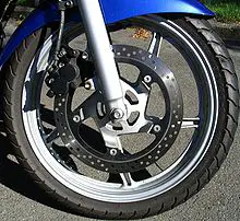
Image: Disc brake

Image credits: anonymous, Disc brakeCC BY-SA 3.0

Define brake fluid types

Brake fluids are of four types. The designation of these brake fluids start with DOT that means Department of Transportation. The four types are-

DOT 3

DOT 3 is a glycol based braking fluid. The term is a standard term used in US. DOT 3 is equivalent to SAE J1703.

DOT 4

DOT 4 is also a glycol based braking fluid generally used as a temperature upgrade for DOT 3. Most cars after 2006 used DOT 4 brake fluid as their standard braking fluid.

DOT 5

A braking fluid that is silicone based and also it is completely different from the series of DOT (2,3,4,5.1) It does not mix with water and other brake fluids. It is recommended that this braking fluid should not be mixed with other braking fluids.The biggest advanatage of silicone over other materials is that silicone based fluid has more stable viscosity index with working conditions having a wide variety of temperature values.

DOT 5.1

Although, DOT 5 was a better version among other DOT versions. Lack of its acceptance led rise to DOT 5.1 which is again a glycol based braking fluid. It gives functioning similarities with silicone based braking fluid and can be termed as non silicone version of DOT 5. That is a version having similar properties of DOT 5 while using Glycol ether based raw materials.

Brake fluid properties

The braking fluid undergoes extreme conditions as the vehicle runs sometimes on smoother road and sometimes on rough and bumpy road. The weather may be hot sometimes, rainy sometimes and sometimes cold.

According to these conditions the braking fluid cannot be changed every now and then. So it has to have properties such that it can bear extreme situations. The ideal properties for a braking fluid are-

  • High breaking point- As the vehicle experiences immense heating during its operation, it is recommended to have a braking fluid which can operate at high temperatures.
  • Good low temperature properties– Sometimes the temperatures are below normal levels during cold, at this time the braking fluid may solidify if it does not have good low temperature properties.
  • Good viscous properties- The braking fluid should have an optimum amount of viscosity. It should not be loose and also not thick that it does not move easily.
  • Anti corrosive properties– The braking fluid should have anti corrosive properties otherwise it will corrode the material used in braking lines damaging the entire braking system.
  • Physical stability– A good braking fluid has good physical stability that means it should not get distorted or change its phase once it is subjected to huge amount of force and pressure.
  • Chemical stability- A good braking fluid does not mix with other liquids, it should have good chemical stability. It should maintain its chemical structure and should not be easily contaminated by outside impurities.
  • Compressibility- The entire functionality of braking fluid depends on its compressibility. If the compressibility is not good then it won’t be able to provide required pressure and so the braking system will fail which in turn means that the vehicle won’t be stopped.

Bike brake fluid types

Bikes usually use two types of braking fluids. These fluids are discussed in detail below-

  • DOT fluid- Above section discusses about DOT fluids in detail. They are mostly made of Glycol Ether based materials and generally each higher version has a better working temperature range. Except for DOT 5 which is a silicone based braking fluid and that has better properties than DOT 2, DOT 3 and DOT 4.
  • Mineral oils– This is the normal mineral oil that we purchase from grocery stores. This is generally meant for lighter vehicles such as two wheeler.

DOT brake fluid types

As discussed in the sections above, DOT brake fluids are classified into many types. Typical basis of classification is the working properties and the raw materials used while making the braking fluid.

The types of DOT braking fluid are-

  • DOT 2– Has a low working range of temperature.
  • DOT 3– Has a greater working temperature range than DOT 2.
  • DOT 4- Has even greater working temperature range than DOT 2 and DOT 3.
  • DOT 5- This is made up of silicone based materials and has better properties.
  • DOT 5.1– Although made of Glycol Ether based materials, it has similar properties as that of DOT 5.

Car brake fluid types

In cars usually glycol ether based brake fluids and silicone based brake fluids are used. These fluids are discussed in above sections. Most commonly used braking fluids in cars are DOT brake fluids. More specifically, following DOT brake fluids are used-

  • DOT 3- As discussed above it is a Glycol Ether based braking fluid that is used in lighter vehicles. This braking fluid can be used in hatchback cars that are light in weight. It has a smaller range of working temperature.
  • DOT 4- As discussed above, it is also a Glycol Ether based braking fluid that is used for comparatively heavier vehicles such as SUVs. This braking fluid has a greater working temperature range.

Auto brake fluid types

In autos, usually DOT 3 type of braking fluid is used. As an auto is considered in lighter weight vehicle type, it does not need higher versions of braking fluid like DOT 4 and 5. DOT 3 is sufficient for autos.

Boiling Point And Pressure: What, How, Relationship, Effects And Detailed Facts

Boiling

This article discusses about the relation between boiling point and pressure. A misconception lies among us that the boiling point is related to temperature only. But primarily it is the pressure which is responsible for the boiling to take place.

The boiling of liquid starts when the vapour pressure of the liquid starts touching the value of ambient or surroundings pressure. The pressure at which boiling takes place is called as saturation pressure. Pressure of the liquid keeps on increasing with increasing temperature. We shall study more about this relationship in this article.

What is partial pressure?

In simple words partial pressure is defined as the pressure exerted by a certain type of liquid molecules in a mixture.

This pressure is the exact same pressure that the liquid molecules must have exerted if these were the only molecules occupying the whole volume. Partial pressure term comes into play when there are more than one type of liquid molecules present in the system.

What is vapour pressure?

Vapour pressure is the pressure exerted by the liquid molecules when they are about to change into gaseous molecules.

The vapour pressure increases with temperature. The surface of the liquid starts boiling when the surface vapour pressure is equal to the ambient pressure. The atmosphere exerts some pressure on the liquid, when this value of atmospheric pressure is reached by vapour pressure, boiling starts taking place. 

How does pressure affect boiling point?

Pressure, as discussed above, is one of the most important factor that affects directly the boiling point of any liquid.

For the surroundings, if the surrounding pressure is very high, it will take more time and more heat for the liquid to reach the ambient pressure value and hence the boiling point of the liquid will be more. When the ambient pressure is low then the liquid will reach the ambient pressure value soon. In this case, the boiling point will be lower as compared to boiling point at surroundings with high pressure.

Boiling point and pressure relationship

Now we have a clear view of how pressure affects the value of boiling point. The main factor affecting the boiling point is atmospheric pressure. (Although temperature also plays an active role)

We shall focus our discussion on relation between pressure and boiling point only. Lets us assume that the heat transfer rate is constant. This way the liquid molecules will slowly get heated up resulting in increase in their vapour pressure. As the vapour touches the ambient pressure, the liquid will start boiling.

boiling point and pressure
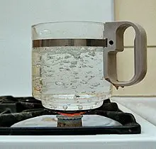
Image: Boiling

Image credits: user:Markus SchweissKochendes wasser02CC BY-SA 3.0

Boiling point and pressure equation

The equation which draws the relationship between boiling point and pressure numerically is called as Clausius-Clapeyron equation.

The Clausius-Clapeyron equation is given below-

gif

Does boiling point increase with pressure?

As and when the pressure of the ambient increases, the boiling point also increases but only upto the critical point.

It is the point where the properties of both the phases, that is, liquid and gases, are exhibited by the substance. We shall more about critical point in later sections of this article. Also, we can note this fact that the boiling point of the liquid decreases when the pressure drops until the triple point is reached.

How does boiling point increase with pressure?

The boiling point can be defined as the value of temperature at which the vapour pressure of liquid becomes equal to the ambient pressure. This value of temperature depends on the ambient pressure.

If the ambient pressure is more, it takes more time for the liquid’s vapour pressure to reach the value ambient pressure. The heat source constantly supplies heat to the liquid to increase its pressure. When the pressure at the outside is more then the boiling time will also be more.

How does water boil at low pressure?

At low pressures, the water starts boiling in a very short time. This is because the time required for the vapour pressure to reach the value of ambient pressure is less.

A notable example is that the food is cooked very fast on mountains. This is because the ambient pressure is very less compared to the pressure at sea level. The liquid takes more time to boil when it is at sea level. 

Does water boil faster at high or low pressure?

We have discussed rigorously about the effect of pressure on boiling point. It is made to us very clear that the water will start boiling faster at lower pressures.

The reason being the same as discussed above. That is, the time required for the vapour pressure to reach the value of ambient pressure is less. The water starts boiling when the vapour pressure reaches the value of ambient pressure.

Factors affecting boiling point

We have discussed a lot of things about what affects the boiling point. Let us get a more detailed view on these factors.

The factors affecting the boiling point are given below-

  • Temperature– Temperature is responsible for increasing or decreasing the vapour pressure of the liquid. When the temperature is high, the vapour pressure increases and likewise, when the pressure is low, the vapour pressure decreases.
  • Vapour pressure– When the vapour pressure reaches the value of ambient pressure, the liquid starts boiling. The pressure exeerted by the liquid when it is about to change its phase is called as vapour phase.  
  • Atmospheric pressure– As the name suggests, the atmospheric pressure is the pressure exerted by atmosphere. Atmospheric pressure plays a very important role in determining the boiling point of the substance. If the pressureexerted by atmosphere is less then the boiling point will also be less and on the other hand the boiling point will be more if the pressure exerted by the atmosphere is more.

What is critical point?

Simply put, critical point of a substance is that point at which the properties of liquid such as density, temperature, pressure etc are equal to that of its own gaseous state.

This can be said as an equilibrium state where the substance exists in both the liquid and gaseous phase. The molecules exhibit properties of both liquids and gases at the same time.

What happens at critical point?

When the temperature of the liquid is raised, the density of the liquid falls down and simultaneously the density of gas starts increasing.

When the densities of both liquid and gas become equal, then the particular point is called as critical point. Here both gas and liquid phase properties are exhibited by the substance.

13 Thermal Conduction Examples: Detailed Explanations

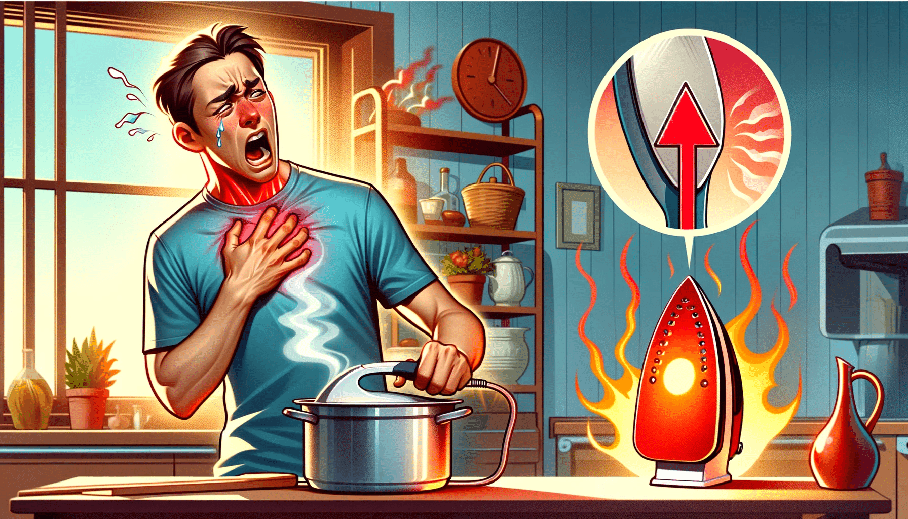
feeling hot after touching a hot object

This article discusses about thermal conduction examples. It is a mode of heat transfer which takes place by the collision of molecules present in the medium.

Heat is the energy existing between two difference which are thermally different from each other that is they both are having different temperatures. The heat energy flows just like the wind. It flows from the higher to lower temperature system. Out of which thermal conduction is one such type.

Thermal conduction examples

We can see thermal conduction taking place almost every day in our daily lives. It is responsible for us getting burnt when we touch a hot object. Let us see different examples of thermal conduction. They are given below-

Spoon getting hot when in contact with hot vessel

The molecules of vessel are continuously vibrating at high energies. This energy is transferred to the molecules of spoon which in turn gets hot. This way the transfer of heat takes place between the spoon and vessel through thermal conduction.

Spoon getting hot when in contact with hot vessel

We feel hot after touching a hot object

Similar to the spoon and vessel example, the molecules of hot object transfers the energy to our skin, this gives us sensation of heat. This is also an example of thermal conduction as the sensation of heat occurs after contact.

We feel hot after touching a hot object

Warming of muscles using heating pad

The heating pad has high energy molecules, this energy is transferred to the skin and then to the muscles. This way we feel relaxed once the heat reaches our muscles. This is also an example of thermal conduction.

Heat from liquid makes the cup hot

The molecules of heat are flowing with high energy, this energy is transferred to the surface of the cup which is contact with the liquid.

Heat from liquid makes the cup hot

Holding warm hands make your hands warm too

A warm hand has more energy than the colder hand. The colder hand becomes warm once the energy is transferred to it. The energy transfer takes place until both the hands come at same temperature.

Ironing clothes

The hot iron transfers heat to the clothes. This is an example of thermal conduction between clothes and iron.

Ironing Clothes

Walking on hot sand

Hot sand transfers heat to our feet when we walk on it. This is why our feet are burnt when we walk on sand with very high temperature. The thermal conduction takes place between feet and sand.

walking on hot sand

Touching a light bulb

The surface of the light bulb is very hot. Upon touching it, the heat is transferred from the surface of the light bulb to our hands which is why we feel warm after touching it.

Touching a light bulb

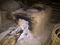
Touching a hot stove

The stove is at higher energy state, after touching which, our hands are burnt due to heat transfer between stove and our hand.

thermal conduction examples
Image: Stove surrounded with bricks prevents our hands from gettign burnt

Image credits: OkkisafireIndonesian brick stoveCC BY-SA 4.0

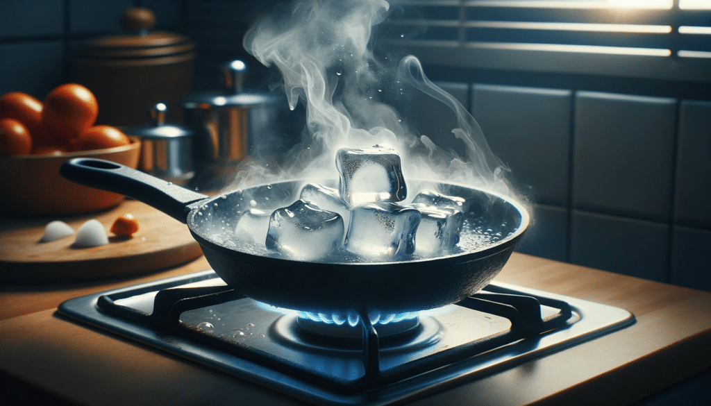
Melting of ice when placed on hot pan

Hot pan transfers heat to the block of ice. Ice starts melting once the temperature starts increasing beyond 0 degrees. As the heat is transferred from the pan, the temperature of the ice block increases and starts melting.

Melting of ice when placed on hot pan

Melting chocolate in hand

Similar to the ice block example, the chocolate starts melting once it absorbs heat from one’s hand. This is due to thermal conduction.

Shallow frying of food such as cutlet

Shallow frying includes heat transfer from pan to the cutlet. Thermal conduction takes place between cutlet and the pan.

Touching a silencer of vehicle

Silencer becomes hot once the vehicle is started and used it for a while, the heat from the silencer is transferred immediately to our leg/hand when we touch it. This is due to a large temperature difference between both. It is recommended that we stand away from silencers as they get very hot sometimes specially right after using the vehicle.

Putting hands in hot water

The energy from hot water is transferred to the hands. This way thermal conduction takes place between hot water and hand.

Touching ice

Ice is colder than our hands, so the heat is being transferred from our hands to the ice block. This happens with the help of thermal conduction between ice block and our hands.

What is heat?

The energy flowing between the two systems solely because their temperatures are different is called as heat.

The flow of heat takes place in a similar way of how wind blows. System at higher temperature is the source of heat flow, the heat goes from this system to the system which is at lower temperature.  For heat to flow otherwise, it needs external help of devices like heat pump.

We shall see about different types of heat transfer in this article.

Modes of heat transfer

The transfer of heat from system to system can take place through various methods. Sometimes it needs a medium and sometimes it travels in vacuum.

We shall see different ways by which heat can be transferred from one system to another. They are discussed below-

  • Heat transfer by conduction- Heat conduction is a mode of heat transfer in which it is transferred with the help of collision of molecules present in the medium. The molecules keep vibrating and transfer the energy from on object to other. This type of heat transfer requires both the objects to be in contact.
  • Convection– Convection is a mode of heat transfer in which the heat is transferred as a result of movement of fluid particles between the two mediums. The fluid can be water or even air This is why we feel hot when we stand near boiling water.
  • Radiation– This form of heat transfer can take place in vacuum and is defined as the heat transfer which takes place in the form of waves or particles through space.

What is thermal conduction?

Thermal conduction is a type of heat transfer that takes place between two systems which are in contact.

The molecules inside these systems collide with each other for transferring the heat form one place to other. This type of heat conduction needs contact between two systems compulsorily for heat transfer to take place.

What is thermal conductivity?

Similar to electrical conductivity that is the ability of a material to conduct electricity, thermal conductivity also means the ability of a material to conduct transfer of heat.

Even the shape of cross section can affect the value of thermal conductivity. We shall study more about thermal conductivity in the sections below.

Heat transfer through different cross sections

Heat transfer also depends on the shape of the cross section. For a cylinder its different, for sphere its different and for a cuboid is different.

The formula for heat transfer for different shapes are given below-

  • Rectangular slab-

The heat transfer through a rectangular slab takes place normal to the cross section. The formula for heat transfer for a rectangular slab is given below-

gif

where,

k is the thermal conductivity of the material

A is the cross section area

Delta T is the temperature difference between the two ends of slab

Delta x is the length of heat transfer

  • Sphere-

The formula for heat transfer through spherical shell is given below-

gif

where,

a and b are the radii of outer and inner sphere respectively

Ta is the temperature at the surface of sphere with radius a

Tb is the temperature at the surface of sphere with radius b

  • Cylindrical shell-

The cylindrical shell, comprising two cylinders with an inner radius ( b ) and an outer radius ( a ), follows a specific formula for heat transfer. The formula is expressed as ( Q = 2\pi kL \left( \frac{Ta - Tb}{\ln{\frac{b}{a}}} \right) ), where ( Q ) represents the heat transfer rate.

where,

a is the radius of outer cylinder

b is the radius of inner cylinder

Ta is the temperature of surface of outer cylinder

Tb is the temperature of surface of inner cylinder

How To Find Constant Velocity: Different Approaches And Problem Examples

constant velocity 0

Constant velocity refers to the motion of an object where its speed remains unchanged and its direction of motion remains constant over time. It is an essential concept in physics and is often used to analyze various kinds of motion, such as linear motion or motion along a curve. In this blog post, we will explore how to find constant velocity, the factors that influence it, and its practical applications.

How to Calculate Constant Velocity

how to find constant velocity
Image by en:User:Anrp – Wikimedia Commons, Wikimedia Commons, Licensed under CC BY 2.5.

The Equation for Constant Velocity

To calculate constant velocity, we use the equation:

 \text{Constant Velocity (v)} = \frac{\text{Change in Position (Δx)}}{\text{Change in Time (Δt)}}

This equation states that the constant velocity is equal to the change in position divided by the change in time. It provides a straightforward way to determine the velocity of an object when its speed remains constant.

How to Use the Constant Velocity Formula

Let’s break down the steps involved in using the constant velocity formula:

  1. Determine the initial and final positions of the object.
  2. Calculate the change in position (Δx) by subtracting the initial position from the final position.
  3. Determine the time elapsed between the initial and final positions.
  4. Calculate the change in time (Δt) by subtracting the initial time from the final time.
  5. Substitute the values of Δx and Δt into the constant velocity formula to find the velocity.

Worked Out Examples on Calculating Constant Velocity

Now, let’s work through a couple of examples to solidify our understanding of constant velocity calculations.

Example 1:

Suppose a car travels 100 meters in 20 seconds along a straight road. What is its constant velocity?

Given:
Initial position (x1) = 0 meters
Final position (x2) = 100 meters
Initial time (t1) = 0 seconds
Final time (t2) = 20 seconds

Using the formula, we can calculate the constant velocity:

 \text{Constant Velocity (v)} = \frac{\text{Change in Position (Δx)}}{\text{Change in Time (Δt)}}

 v = \frac{100 \, \text{m} - 0 \, \text{m}}{20 \, \text{s} - 0 \, \text{s}} = \frac{100 \, \text{m}}{20 \, \text{s}} = 5 \, \text{m/s}

Therefore, the car’s constant velocity is 5 meters per second.

Example 2:

Suppose a person walks a total distance of 1200 meters in 10 minutes. What is their constant velocity?

Given:
Initial position (x1) = 0 meters
Final position (x2) = 1200 meters
Initial time (t1) = 0 minutes
Final time (t2) = 10 minutes

Converting minutes to seconds:
Initial time (t1) = 0 minutes × 60 seconds/minute = 0 seconds
Final time (t2) = 10 minutes × 60 seconds/minute = 600 seconds

Using the formula, we can calculate the constant velocity:

 v = \frac{1200 \, \text{m}}{600 \, \text{s}} = 2 \, \text{m/s}

Therefore, the person’s constant velocity is 2 meters per second.

Factors Influencing Constant Velocity

Role of Acceleration in Constant Velocity

In the context of constant velocity, it is important to note that acceleration is zero. Acceleration is defined as the rate of change of velocity with respect to time. Since constant velocity implies a constant speed, there is no change in velocity over time, resulting in zero acceleration.

Impact of Friction on Constant Velocity

Friction plays a crucial role in determining the constant velocity of an object. In the absence of external forces, such as friction, an object in motion will continue to move at a constant velocity. However, when friction is present, it opposes the motion of the object, potentially causing a decrease in velocity. In some cases, the force of friction can balance with other forces, resulting in a constant velocity despite its presence.

How Distance and Time Affect Constant Velocity

The concept of constant velocity heavily relies on the relationship between distance and time. If an object covers the same distance in the same amount of time, it indicates a constant velocity. However, any changes in distance or time can lead to a change in velocity. Therefore, it is important to analyze changes in these factors when considering constant velocity.

Practical Applications of Constant Velocity

constant velocity 1

Checking Constant Velocity Joint

Constant velocity (CV) joints are commonly used in vehicles to transmit torque smoothly while allowing for a range of motion. The ability to maintain constant velocity is crucial for smooth and efficient operation. By checking the velocity of the CV joint, mechanics can ensure that it is functioning properly and not causing any issues, such as vibrations or jolts during acceleration.

Finding Constant Velocity in Physics

In physics, constant velocity is often used to analyze the motion of objects in various scenarios. By determining the constant velocity of an object, physicists can make predictions about its future behavior and understand the underlying principles governing the motion.

Using Constant Velocity in Real-World Scenarios

how to find constant velocity
Image by User:Pwld – Wikimedia Commons, Wikimedia Commons, Licensed under CC BY-SA 4.0.

Constant velocity has practical applications in many real-world scenarios. For example, in sports such as athletics or swimming, measuring the constant velocity of an athlete can provide insights into their performance and potential improvements. Additionally, in transportation and logistics, understanding the constant velocity of vehicles can help optimize routes and improve efficiency.

These are just a few examples of how constant velocity is applied in different fields, highlighting its significance in various aspects of our lives.

By understanding how to find constant velocity, the factors that influence it, and its practical applications, we can gain a deeper insight into the world of motion and its implications across different disciplines.

Remember, constant velocity is not just a mathematical concept, but a fundamental aspect of how objects move and interact in the world around us.

Numerical Problems on how to find constant velocity

constant velocity 3

Problem 1:

constant velocity 2

A car travels a distance of 200 meters in 10 seconds. Determine its constant velocity.

Solution:

Given:
Distance, d = 200 \, \text{m}
Time, t = 10 \, \text{s}

We know that velocity \(v) is given by the formula:

v = \frac{d}{t}

Substituting the given values, we get:

v = \frac{200}{10}

Hence, the constant velocity of the car is 20 m/s.

Problem 2:

A cyclist covers a distance of 5 kilometers in 30 minutes. Find the constant velocity of the cyclist.

Solution:

Given:
Distance, d = 5 \, \text{km}
Time, t = 30 \, \text{min}

First, we need to convert the time from minutes to hours. Since 1 hour equals 60 minutes, we have:

t = \frac{30}{60} = \frac{1}{2} \, \text{hour}

Now, we can calculate the constant velocity using the formula:

v = \frac{d}{t}

Substituting the given values, we get:

v = \frac{5}{\frac{1}{2}}

Simplifying, we get:

v = 10 \, \text{km/h}

Therefore, the constant velocity of the cyclist is 10 km/h.

Problem 3:

A train covers a distance of 500 miles in 5 hours. Determine its constant velocity.

Solution:

Given:
Distance, d = 500 \, \text{miles}
Time, t = 5 \, \text{hours}

We can calculate the constant velocity using the formula:

v = \frac{d}{t}

Substituting the given values, we get:

v = \frac{500}{5}

Simplifying, we get:

v = 100 \, \text{miles/hour}

Hence, the constant velocity of the train is 100 miles/hour.

Also Read:

Steam Table Of water: for Liquid, Subcooled, Saturated, Superheated, Compressed

Saturated water table 274x300 1

This article discusses about steam table of water. Before studying about steam table of water, we will first understand the meaning of steam table, steam and its properties.

As water has liquid form, its gaseous form is called as steam. When we heat water enough to a temperature of 100 degrees celsius, then the liquid temperature starts converting to gas or steam. Let us discuss about steam and steam tables further in this article.

What is steam?

When water is heated to a certain temperature, it starts getting converted to a different phase. The liquid form of water gets converted to gaseous phase called as steam.

The conversion starts taking place at saturation temperature where both the phases of water co-exist with each other. Slight increase in temperature results in steam formation and slight decrease in temperature results in formation of liquid water.

Types of steam

Usually steam contains particles of liquid particles, but at certain temperatures the liquid particles also evaporate to become steam. This gives rise to a new type of steam.

Let us discuss abut different types of steam in the section given below. The types of steam are-

  • Wet steam– As discussed above, steam contains particles of liquid water. The resulting steam and water mixture is called as wet steam.
  • Saturated steam– The steam existing at saturation temperature is called as saturated steam. At this temperature the phases of water/steam co exist with each other. Any increase or decrease in temperature results in superheated steam or wet steam respectively. In this state, the vapour-liquid equilibrium is established.
  • Superheated steam– After heating the steam beyond the saturation temperature, the resulting steam we get is called as superheated steam .This steam is pure steam and no liquid particles are present in superheated steam.

Uses of steam

The steam can be used in many industrial applications. These applications are mentioned below.

Uses of steam are-

  • Agricultural uses– In agriculture, a soil sterilizing method is used to sterilize the soil. This is done with the help of steam in open fields or green houses.
  • Atomization– Atomization of certain fuels used in burners is done with help of steam. Here the steam is used to separate the fuel mechanically.
  • Chemical uses– The chemical industry uses steam for humidifying, atomization, cleaning, sterilization etc purposes.
  • Mechanical uses– The steam engines use steam for running locomotives such as steam train. The mechanical energy is produced using the thermal energy produced while making the steam.
  • Concrete treatment– The curing of concrete is done with the help of steam. It improves the mechanical properties of concrete. It accelerates the compressive strength of concrete.
  • Cleaning– With the help of soot blowers, the team can be used for cleaning purposes. In boilers, steam is used to clean the boiler surface.
  • Sterilization– In various industries, the steam is used to sterilize the bottles so that any contaminants present can be cleaned and removed from the surface.
  • Electricity generation– The use of turbines in electricity generation is known to us. The freshly prepared steam is injected to the blades of turbine. These blades start rotating with the help of which the electricity is generated.

What is sub cooled water?

The term sub cool means that the liquid substance is existing below its normal boiling temperature. For water it is generally below 373 K or 100 degree celsius.

Below section provides a clear insight on steam table of sub cooled water. Subcooled water is used in expansion valve and compression safety.

Steam table for sub cooled water

Below given is the steam table for sub cooled water. The temperature and pressure discussed in this article are under certain range only. In actual the steam tables exist for a wide variety of values of pressure and temperatures.

steam table of water
Image: Table for Sub cooled water

What is saturated water?

The term saturation means that water is in a equilibrium state. The equilibrium occurs between the gaseous phase, that is, steam and the liquid state, that is, water.

Any increase in temperature will convert the vapour-liquid mixture to pure vapour and any decrease in temperature will convert the vapour-liquid mixture into liquid. It can be said that saturated state is a transition state of any liquid to gas or gas to liquid. The region under the saturation line comes under saturated region where liquid phase and vapour phase co exist and are in equilibrium with each other.

Steam table for saturated water

The steam table for saturated water is given in the table below. The steam table exists for a wider range of pressure and temperature values, here only a limited range is discussed.

Saturated water table
Image: Steam table for Saturated water

What is compressed water?

Compressed water and sub cooled water are same in nature. Compressed fluid means it is under a mechanical or thermodynamic condition that forces it to be below saturation conditions. The region situated at left hand side of the saturation line is called as the sub cooled region. The dryness fraction in this region is 0.

What is superheated water?

Superheated means that the substance is heated above its saturation temperature. A liquid in such a state will start vaporising completely leaving behind no liquid particles.

The enthalpy of superheated water is much higher than that of sub cooled water. In a Mollier diagram, the region situated at right hand side of the saturation line is called as the superheated region. The dryness fraction of the substance is 1 in this region.

Steam table for superheated water

Superheated water is also called as superheated steam. This steam has no liquid water particles in it. The steam table for compressed water also exists for a wide range of temperature and pressure values, here only a limited range is being discussed.

Compressed water
Image: Steam table for compressed water

Mollier diagram

A Mollier diagram is a graphical representation of various thermodynamic properties of steam/air such as temperature, pressure, enthalpy and moisture content.

The Mollier diagram is used by design engineers while designing a power plant, the data is used for checking properties of the air at different temperature and pressure values. Mollier diagram is a very convenient design tool for thermal engineers.

Master Cylinder Types: Working Process

master cylinder

This article discusses about master cylinder types, places where it is used and its working mechanism. The braking force applied by the driver is very less as compared to the actual force needed to stop the vehicle.

A master cylinder amplifies this braking force and is used to convert a mechanical force into hydraulic force. The hydraulic force is then again used for performing mechanical activities such as lifting weights or braking a car.

What is a master cylinder?

A master cylinder is a device used to convert a mechanical force to hydraulic force. This cylinder then controls the slave cylinders attached to the other end of the braking system.

A master cylinder is usually used in automotive industry mainly used to apply hydraulic pressure. These cylinders are commonly used in braking systems in automobiles. It is a very important machine component.

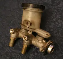
master cylinder types
Image: Master cylinder

Image credits: Ildar Sagdejev (Specious), 2008-04-21 1990 Geo Storm GSi master cylinderCC BY-SA 4.0

Need of a master cylinder

A master cylinder is used in hydraulic braking systems of automobiles. The need of using a hydraulic brake over a mechanical brake arises due to many reasons. They are-

  • Due to very high speed of vehicles, the braking force needed to stop the automobiles within a specified distance is much higher. Here the mechanical brakes fail, only hydraulic brakes can provide such a high braking force with utmost safety.
  • The front wheels require more braking force as the mass shift towards the front side of the vehicle during braking. This distribution of force can be done with the use of a master cylinder.
  • A driver typically applies a braking force in the range of 50-70 N. This is not enough for stopping the vehicle. A master cylinder multiplies this force which helps in stopping the vehicle.
  • Master cylinder acts as a converter that is it converts mechanical force applied on the brake pedal to hydraulic force which then is used for stopping the vehicle.
  • The use of master cylinder decreases the risk of failure as it creates independent braking system of front and rear wheels. This way the design is safer in comparison to conventional braking system.

Master cylinder types

Master cylinder can be classified into two types. The classification of master cylinder is done on the basis of number of cylinders used in the braking circuit of the braking system. 

The following are the types of master cylinder-

  • Single circuit master cylinder– As the name suggests it consists of only one cylinder. For example a medical syringe. It uses only one cylinder for braking system. Such type of master cylinder circuit is used in light weighted vehicles such as two wheeler and small four wheeler cars. This type of circuit master cylinder distributes equal amount of braking force to all the wheels as it contains only one cylinder.
  • Tandem or dual circuit master cylinder– In the name it suggests that there are more than one circuits of master cylinders which are used for braking systems. Tandem circuit can be used where independent braking system is required for front and rear wheels. It is used in almost all cars because of its higher efficiency. This is also a safer design for vehicle braking system.

Master cylinder parts

A single circuit master cylinder consists of many parts. We will study about them in the description given below-

Reservoir

The reservoir stores the braking fluid. It is the hydraulic fluid used in braking system. Reservoir is generally made up of plastic.

Cylinder

This acts as a housing for piston. Inside the cylinder, movement of piston takes place. The material used for making cylinder is cast iron and aluminium. The cylinder is connected to reservoir through its inlet valve and to braking lines with the help of outlet valves.

Piston

The piston is the main part which exerts force on the braking fluid. As the brake pedal moves, the piston performs reciprocating motion due to which the hydraulic force is generated. This force is then converted to mechanical force.

Returning spring

It is commonly known fact that potential energy is stored inside a spring when it is deformed from its original shape. This potential energy helps the spring to come back to its original shape. In master cylinder also, returning spring is used for the braking pedal and piston to come to its original position.

Valve

Valve is the outlet portion through which the braking line is attached. The braking fluid is compressed and passes further to caliper through this valve.

Working of a single circuit master cylinder

We shall study the working of single circuit master cylinder in brief. When the brakes are not applied, the the braking fluid does not enter the braking lines.

The braking fluid enters the compression chamber as soon as the brakes are applied. This fluid is compressed due to movement of piston. The braking fluid after attaining a certain compressed pressure, is released to the braking lines due to which the brakes are applied to stop the vehicle.

Working of a tandem circuit master cylinder

The working of both tandem circuit master cylinder and single circuit master cylinder is majorly similar. The only difference between both of them is that in tandem circuit, more than one cylinder is used for braking circuit.

In tandem circuit, after the actuation of primary circuit the secondary circuit is actuated. The braking pressure from first circuit is transferred to the second circuit. This way tandem circuit master cylinder applies braking force from more than one cylinder. It is a safer design for braking systems in vehicles.

Applications of single circuit master cylinder

As the name suggests only one single cylinder is used for braking application in single circuit master cylinder. It is used for light weight vehicles.

The applications of a single circuit master cylinder are-

  • It is used in braking systems of two wheelers like Bajaj, TVS and Apache etc.
  • It is also used in braking systems of various e-rickshaws which are light in weight.

Applications of tandem circuit master cylinder

Tandem circuit master cylinder uses more than one cylinder for braking system.

The applications of a tandem circuit master cylinder are-

  • It is commonly used in all kinds of four wheeler automobiles which are equipped with hydraulic braking systems.
  • Used in heavy duty vehicles because it provides a safer braking application than single circuit master cylinder.

Is Angular Velocity Constant?

is angular velocity constant

Angular velocity is a fundamental concept in physics that describes the rate of change of an object’s angular displacement. The question of whether angular velocity is constant depends on the specific context and the motion being studied.

Uniform Circular Motion

In uniform circular motion, the angular velocity is constant. This means that the object moves in a circle at a constant speed, and the angular displacement changes at a constant rate. The angular velocity (ω) is defined as the rate of change of the angular displacement (θ) with respect to time (t):

\omega = \frac{\text{d}\theta}{\text{d}t}

For uniform circular motion, ω is constant, which implies that the angular displacement changes at a constant rate over time.

Examples of Uniform Circular Motion

  1. Spinning Top: A spinning top maintains a constant angular velocity as it rotates around its central axis.
  2. Ferris Wheel: The angular velocity of a Ferris wheel is constant, as each passenger car completes one full revolution in the same amount of time.
  3. Centrifuge: In a centrifuge, the samples rotate at a constant angular velocity, which is crucial for separating substances based on their density.

Formulas and Calculations

The constant angular velocity (ω) in uniform circular motion can be used to calculate other important quantities:

  • Angular Displacement (θ): θ = ω * t
  • Tangential Velocity (v): v = ω * r, where r is the radius of the circular path.
  • Centripetal Acceleration (a): a = ω^2 * r

For example, if a Ferris wheel has an angular velocity of 0.2 rad/s and a radius of 20 meters, the tangential velocity of a passenger car would be:

v = ω * r
v = 0.2 rad/s * 20 m
v = 4 m/s

Angular Velocity in Rotating Systems

is angular velocity constant

In rotating systems, such as a spinning disk or the Earth’s atmosphere, the angular velocity can also be constant. This means that all points on the rotating body have the same angular velocity, regardless of their radial distance from the center of rotation. The angular velocity is a property of the body or the reference frame and does not depend on the location where it is measured.

Examples of Constant Angular Velocity in Rotating Systems

  1. Earth’s Atmosphere: The atmosphere rotates with the same angular velocity as the Earth, which is approximately 15 degrees per hour or 7.27 × 10^(-5) rad/s.
  2. Spinning Disk: The angular velocity of a spinning disk remains constant for all points on the disk, regardless of their radial distance from the center. This is because every point on the disk completes one full revolution in the same amount of time.
  3. Rotating Machinery: In industrial machinery, such as turbines and generators, the rotating components often maintain a constant angular velocity to ensure efficient and stable operation.

Theoretical Explanation

The constancy of angular velocity in rotating systems can be explained by the definition of angular velocity as the rate of change of angular displacement. Since all points on the rotating body complete one full revolution in the same amount of time, their angular velocity remains constant. This is in contrast to tangential velocity, which varies with radial distance due to the increasing circumference of the circle at greater distances from the center.

Formulas and Calculations

The key formulas and theorems related to constant angular velocity in rotating systems are:

  • Angular Velocity: ω = dθ/dt
  • Tangential Velocity: v = ω * r
  • Angular Displacement: θ = Δs/r

For example, if a spinning disk has an angular velocity of 10 rad/s and a radius of 0.5 meters, the tangential velocity of a point on the disk’s edge would be:

v = ω * r
v = 10 rad/s * 0.5 m
v = 5 m/s

Numerical Problems and Data Points

  1. Spinning Top: A spinning top has an initial angular velocity of 50 rad/s. If the top maintains a constant angular velocity, calculate the angular displacement after 10 seconds.

“`
Given:
Initial angular velocity (ω) = 50 rad/s
Time (t) = 10 s

Angular displacement (θ) = ω * t
θ = 50 rad/s * 10 s
θ = 500 rad
“`

  1. Ferris Wheel: A Ferris wheel has a radius of 20 meters and a constant angular velocity of 0.2 rad/s. Calculate the tangential velocity of a passenger car at the top of the wheel.

“`
Given:
Radius (r) = 20 m
Angular velocity (ω) = 0.2 rad/s

Tangential velocity (v) = ω * r
v = 0.2 rad/s * 20 m
v = 4 m/s
“`

  1. Earth’s Atmosphere: The Earth’s atmosphere rotates with a constant angular velocity of 7.27 × 10^(-5) rad/s. Calculate the time it takes for the atmosphere to complete one full revolution around the Earth.

“`
Given:
Angular velocity (ω) = 7.27 × 10^(-5) rad/s

Time for one full revolution (T) = 2π / ω
T = 2π / (7.27 × 10^(-5) rad/s)
T = 24 hours
“`

  1. Spinning Disk: A spinning disk has a radius of 0.5 meters and a constant angular velocity of 10 rad/s. Calculate the centripetal acceleration of a point on the disk’s edge.

“`
Given:
Radius (r) = 0.5 m
Angular velocity (ω) = 10 rad/s

Centripetal acceleration (a) = ω^2 * r
a = (10 rad/s)^2 * 0.5 m
a = 50 m/s^2
“`

These examples demonstrate the application of the formulas and theorems related to constant angular velocity in both uniform circular motion and rotating systems.

Conclusion

In summary, angular velocity can be constant in two main scenarios:

  1. Uniform Circular Motion: In uniform circular motion, the angular velocity is constant, meaning the object moves in a circle at a constant speed, and the angular displacement changes at a constant rate.

  2. Rotating Systems: In rotating systems, such as a spinning disk or the Earth’s atmosphere, the angular velocity can also be constant, with all points on the rotating body having the same angular velocity, regardless of their radial distance from the center of rotation.

The constancy of angular velocity in these cases can be explained by the definition of angular velocity as the rate of change of angular displacement. Understanding the concept of constant angular velocity is crucial in various fields of physics, engineering, and astronomy, as it underpins the analysis and design of many rotating systems and mechanisms.

References

  1. Biomechanics of Human Movement. (n.d.). Retrieved from https://pressbooks.bccampus.ca/humanbiomechanics/chapter/6-1-rotation-angle-and-angular-velocity-2/
  2. Constant Angular Velocity. (n.d.). Retrieved from https://www.sciencedirect.com/topics/engineering/constant-angular-velocity
  3. Constant Angular Velocity. (n.d.). Retrieved from https://www.sciencedirect.com/topics/computer-science/constant-angular-velocity
  4. Why Does the Atmosphere Rotate with Constant Angular Velocity?. (2016, June 18). Retrieved from https://www.physicsforums.com/threads/why-does-atmosphere-rotate-w-constant-angular-velocity.875999/
  5. Why Is Angular Velocity the Same for All Points on a Spinning Disk?. (2020, May 2). Retrieved from https://physics.stackexchange.com/questions/548631/why-is-angular-velocity-the-same-for-all-points-on-a-spinning-disk-even-though

Master Cylinder Diagram: Detailed Explanations

Master cylinder diagram 300x206 1

This article discusses about master cylinder diagram. Before moving towards master cylinder diagram, we will study about what is master cylinder.

If you have driven an automobile, be it a four wheeler or a two wheeler, you must have noticed that you do not need to apply much force on the braking pedal. Just a slight force stops the vehicle running at high speeds. Lets study more about master cylinder in below sections.

What is a master cylinder?

A master cylinder is a device that converts mechanical force to hydraulic force. A master cylinder finds its application in braking system of automobiles (of all types).

It is an integral part of braking system. It amplifies the force that we apply on braking pedal and with the help of hydraulic fluid it stops the vehicle that is running at very high speeds. Without a master cylinder, it would get very difficult to stop at emergency situations. A hydraulic brake is always better than a mechanical brake due to the emergency stopping advantage.

Master cylinder diagram
Image: Master cylinder diagram

Image credits: Fred the Oyster
iThe source code of this SVG is validThis vector image was created with Adobe Illustrator., Master cylinder diagramCC BY-SA 4.0

Types of master cylinder

Master cylinder is classified into two main types. These types are classified solely on the basis of number of cylinders used in the circuit of braking system.

The most common types of master cylinders used in the braking systems are-

  • Single circuit master cylinder– The single circuit master cylinder uses only one cylinder in the braking circuit of the braking system. This way the braking force is distributed equally among all the wheels of the automobile. This type of circuit is quite unsafe and should be used only in light weighted four wheeler vehicles, two wheeler vehicles and e-auto rickshaws.
  • Tandem or dual circuit master cylinder- In Tandem circuit master cylinder, more than one cylinder is used (generally two). This way the braking system can be used independently in front wheels and rear wheels. This improves the safety feature in the design of braking system.

Master cylinder diagram

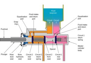
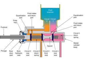
The master cylinder is an assembly of many parts. The main working parts of the master cylinder are shown in the diagram below-

The notable parts shown in the above diagram are- Reservoir, cylinder, piston, valve, spring and braking pedal. We shall study in detail about them in below sections.

Master cylinder parts

As discussed above, master cylinder is an assembly of many working parts. Let us discuss about the main working parts of the master cylinder-

  • Reservoir– Reservoir acts like a storage tank for braking fluid. Braking fluid rests inside the reservoir, when the braking pedal acts then certain amount of braking fluid is taken into the braking circuit.
  • Cylinder– Inside the cylinder, piston movement takes place. When the braking fluid exerts pressure, piston movement takes place inside the cylinder.
  • Piston– Piston transfers hydraulic force from the hydraulic fluid to the brakes. The application of brakes stops the vehicle running at high speeds. Piston rests inside the cylinder.
  • Returning spring– A spring generally stores potential energy inside it when a force is applied on it. This potential energy helps it to regain its original shape back. In a master cylinder, returning spring is used to bring back the piston and braking pedal to their original positions once the braking application is complete.
  • Valve– Valve acts like an outlet portion to which the braking line is attached. The compressed braking fluid passes to the caliper through this valve.
  • Braking pedal– The braking pedal is a lever on which the driver applies the braking force. Although the force applied by the driver is not equal to the actual force required for stopping the vehicle. The force applied on the pedal is transferred to the hydraulic fluid. This fluid exerts hydraulic force to the brakes. The brakes are actuated by this hydraulic force and so the braking application takes place.

Single circuit master cylinder working

The following steps take place while a braking force is applied on single circuit master cylinder.

  • When no braking force is applied, that is when the pedal is idle. The inlet valve is closed and no braking fluid flows through the circuit.
  • When the braking force is applied on the brakes, the inlet valve is opened and the braking fluid flows from the reservoir to the compression chamber.
  • When the braking fluid attains enough compression pressure, it flows through the braking lines and moves the brakes. This way the application of brakes takes place.
  • The master cylinder amplifies the braking force applied by the driver.
  • When the brake pedal is left idle again, the braking fluid returns back to the reservoir.

Tandem or dual circuit master cylinder working

The working of tandem circuit master cylinder is similar to that of single circuit master cylinder. Let us see about its working in detail below-

  • Similar to single circuit master cylinder, the application of braking force on braking pedal activates the primary cylinder or the compression chamber.
  • After the first cylinder is activated, the braking fluid flows through another cylinder also called as secondary cylinder. After the secondary cylinder is activated, another circuit also starts participating in braking application.
  • This way two cylinders participate in the braking application. This feature can also be used to make independent braking system for front wheel and rear wheel.
  • This type of circuit is also safer and is used in almost all four wheeler vehicles.

Need of a master cylinder

As we have discussed above, master cylinder uses hydraulic force for the application of brakes. Hydraulic force is always better than the mechanical force as it can be used in emergency situations with better efficiency.

The need of a master cylinder arises due to multiple reasons. They are-

  • It can allow independent braking systems for front and rear wheels.
  • They can be used in emergency situations with better efficiency.
  • They amplify the force applied on the braking pedal and make it equal to the actual braking force required to stop the vehicle.
  • It decreases the risk of failure because it can be used as independent systems for front and rear wheels.

11 Example Of Heat Energy To Mechanical Energy: Detailed Explanations

Carnot engine

This article discusses about example of heat energy to mechanical energy. Energy can be defined as the power required to do a certain kind of activity.

Energy is an indestructible thing. It is a well known fact that it can neither be destroyed nor be created. It can only change its form from one to another. Here we will study about example of heat energy to mechanical energy.

Example of heat energy to mechanical energy

Energy has a special characteristic that it can not be created nor be destroyed. It is a universal fact. Also, we can see this in our daily lives that heat energy is being converted to mechanical energy and vice versa.

Let us see some examples of heat energy being converted to mechanical energy-

Internal Combustion engine

In internal combustion engines, the fuel is ignited. Ignition of fuel represents heat energy coming into action. The ignited fuel is responsible for movement of piston which in turn is responsible for rotating the crankshaft. This way the heat energy gets converted to mechanical energy.

Turbine

A turbine rotates after steam passes through the turbine blades. The steam comes from the boiler where the liquid water gets converted into steam. This way the heat energy gets converted to mechanical energy.

Rocket engines

The rocket engines emit a huge amount of gases which help the rocket to propel upwards. This upward movement of rocket implies that the heat energy from the engines is getting converted to mechanical energy.

Steam engines

In earlier days, steam engines were used to run trains. The heat generated from burning of coal was used to run the engine. This way the locomotive used heat energy to generate mechanical energy.

Power plants

Power plants use a boiler which heats the liquid water, the water gets converted to steam and rotates the blades of turbine. This is how heat energy is converted to mechanical energy.

example of heat energy to mechanical energy
Image: Carnot engine

Image credits: Wikipedia

Thermal soaring

The atmosphere is unevenly heated. In the regions where temperature is more, the warm currents arise. These warm currents rise up. Birds use these warm currents to generate lift. This way heat energy is used to generate lift.

Geothermal energy

The Earth’s crust is full of hot molten rocks or magma. Due to this heat, the underground water gets heated and plunges out when the accumulated heat exceeds a threshold value. This heat is used for running a turbine which in turn generates electricity.

Pressure cooker

The heat inside the pressure cooker is responsible for the increased pressure inside the cooker. The cooker whistle rises up and allows the excess pressure to move out of the cooker. Rising up of the whistle in an example of mechanical energy. This is an example of heat energy being converted to mechanical energy.

Wind energy

The wind blows as a result of pressure difference as well as temperature differences between two places for instance at coastal regions, cold breeze flows during night and warm breeze flows on the land during day time.

Water currents

The warm currents tend to move in colder regions and vice versa. This produces the water to move from one place to another due to temperature difference.

Firecrackers

In some fire crackers such as rockets and twisters, the heat energy is converted to mechanical energy. Twisters rotate after burning and rockets propel upwards.

What do you mean by energy?

An object requires energy to do work or a certain activity. Without energy we won’t be able to any activities or perform useful tasks.

The different forms of energy that we use to perform daily tasks are kinetic energy, potential energy, thermal energy etc.

Types of energy

Energy is broader term which simply means the capacity or ability to do work or a certain activity. It comes in many forms, these forms can exist in different system and can be converted to another forms of energy.

Let us see different types of energy. They are listed below-

  • Chemical energy– Chemical energy arises from the interaction of reactants in a chemical reaction. The formation of products emits some amount of energy.
  • Mechanical energy– Mechanical energy arises due to the object’s motion or position.
  • Heat/thermal energy- Temperature difference between two two systems gives rise to heat energy. Certain fuels are burnt to generate heat energy which later is converted to other forms of usable energy.
  • Nuclear energy- The atom is bind with the help of nuclear force. If we spit an atom, an immense amount of energy is released which is called as nuclear energy.
  • Electrical energy– The electrical energy arises due to flow of electrons.
  • Gravitational energy- This is a type of mechanical energy which arises due to the object’s height from the ground.

There are other forms of energy such as sound energy, spring energy but they can be listed in one of the sub types of above stated energies. For example spring energy is a type of elastic potential energy

What do you mean by heat energy?

Heat energy can be defined as a type of energy that flows between the two systems whose temperatures are different that is they have a temperature difference between them.

The quantity of heat energy transfer depends on the temperature difference between the systems, it follows a direct proportionality relation. The heat flows from the region of higher temperature to lower temperature. The heat flows until the systems come in thermal equilibrium that is they both attain the same temperature.

How does heat flow from one system to another?

As written in above section, heat will flow from a system which is at higher temperature to a system which is at lower temperature.

The heat will flow until the two systems attain thermal equilibrium that is until their temperatures become equal. When the heat flows, the system with higher temperature gets colder and the system with lower temperature gets hotter.

What do you mean by mechanical energy?

Mechanical energy is defined as a type of energy possessed by an object solely because of its motion or position.

Mechanical energy can be of many types. Broadly, it can be classified as potential energy and kinetic energy. We will read more about it in later sections of this article.

What are the types of mechanical energy?

The energy stored inside an object due to its position or motion is called as mechanical energy. There mainly two types of mechanical energy, they are-

  • Potential energy– This kind of mechanical energy exists in an object due to its position or to be more precise height. Greater the height of an object from the sea level, greater will be the potential energy stored inside the object.
  • Kinetic energy- As the name suggests, kinetic means something related to motion and mobility. The energy in an object which exists only because of its motion can be called as kinetic energy. It follows direct proportional relationship with mass of the object and square of velocity of that object.

Also Read: