Topics of Discussion
1. VHDL Process using Xilinx
2. Steps to Install Xilinx
3. Step by Step Examples for implementation of Sequential & Combinational Circuits.(VHDL Process)
Tutorial with a step-by-step guide for VHDL Process
VHDL Process Using XILINX
To implement VHDL designs, we will use Xilinx. Xilinx is one of the best providers of programming logic devices. It is a tech company based on states.
Prerequisite for using VHDL:
WHAT IS VHDL ? Check Here!
- Must have some knowledge of digital electronics. <You can check out some articles here!>
- It is good if you have an uninterrupted internet connection for downloading the files.
- Xilinx needs at least 18 GB of space in your PC. So make sure that your disk has enough space to run the application.
- Make sure you have created a free account with a valid email id in Xilinx before downloading. That will help you in future purposes.
- We are using windows.
Installation Guide for VHDL Process
- Step 1: Download the zip file according to your operating system and their versions.
The link to download Xilinx is given below.
https://www.xilinx.com/member/forms/download/xef.html?filename=Xilinx_ISE_DS_Win_14.7_1015_1.tar
It is 6.18 GB free zipped file. We will use this version to demonstrate the tutorial.
You can find other downloadable options from here –
- Step 2: Unzip the file and store that in a preferred folder. The folder name should be – Xilinx_ISE_DS_Win_14.7_1015_1. Open this folder.
- Step 3: Double click on the xsetup file (as shown in the image) and start the installing. Allow all the permissions . The installation may take up to two hours depending on the memory space available and the PC configurations. Nothing to worry, sit tight and get it installed.

Choose the ISE webpack from the list when this pop up appears before final installation. Also, keep the default storage space as it suggests and if that location has enough space.

After the installation of the file, there will be two shortcuts appearing in the desktop, and there will be a pop-up regarding the license. Don’t click on the shortcut icons as the installation is not completed and also close the license tab for the time being.
- Step 4: Now, the software is installed inside your computer. Find out the installed folder which is of around 18 GB of size. By default, it gets stored in C drive if you have not made any changes. Open the folder.
Open Xilinx folder -> 14.7 -> ISE_DS -> lib -> nt64
Path – [C:\\Xilinx\\14.7\\ISE_DS\\ISE\\lib\ t64]
- Step 5: Now there will be a file named – “libPortability.dll”
Rename that file as – “libPortability.dll.orig”
- Step 6: Then find out the file named as – “libPortabilityNOSH.dll”. It will be just below the file we worked in step 4. Copy the file and paste it. Now rename that pasted file as – ‘libPortability.dll”. Keep the copied file in the dashboard.
The final outcome will look like the below-given figure.

- Step 7: After that, we have to go to another file-folders.
Open Xilinx folder -> 14.7 -> ISE_DS -> common -> lib -> nt64
Path – [C:\\Xilinx\\14.7\\ISE_DS\\common\\lib\ t64]
There will be a file named as – “libPortability.dll”.
Rename that file as – “libPortability.dll.orig”
- Step 8: Now, paste the file that we have copied in step 6 and rename that pasted file as – ‘libPortability.dll”.
The final outcome will look like the below-given figure.

- Step 9: License: Now double click on the shortcut ISE Design Suite 14.7. There will be a pop-up asking for a license. Just click Okay, and another window will be opened. There will be options for the license. From the “Acquire license”, click on the “Get My Purchased License (s)” and then NEXT.

Then, there will be another pop-up from “Xilinx License Manager”. Click on the connect now option. It will open a tab on the default web browser of your PC.
Log in with your credentials, and there will be options like the below image. You have to choose the 4th or 5th option from the list. Just click on the license you want.
There will be a mail in your email id, containing the license file for Xilinx. Download the license file and store it into the download folder.

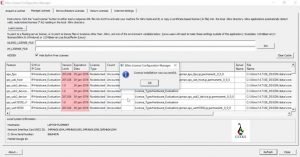
- Step 10: Go back to the ISE. There you can see a window remained open. Choose the option load license and locate your license in the download folder to upload.
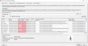
After uploading the license, there will be a message showing successfully. Click Ok and then click close in the previous window. Now Xilinx is ready to be used.
Creating your first project in XILINX (VHDL Process)
We will implement a simple AND gate dataflow modelling using Xilinx. AND gate is represented as – Y= AB. The truth table is shown below.
| A | B | Y =AB |
| 0 | 0 | 0 |
| 0 | 1 | 0 |
| 1 | 0 | 0 |
| 1 | 1 | 1 |
- Step 1: Open the project navigator by double-clicking the icon on the desktop.
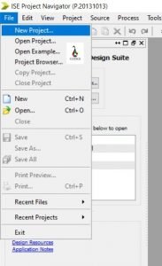
- Step 2: Go to File and then New Project. File -> New Project
- Step 3: Give a name to your project and select the location to store the project. Never uses basic gate names. Then click on the next. Copy the name, and it will help later.
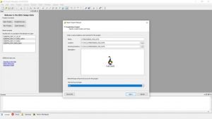
- Step 4: Now set up the values as mentioned below. Do the setup carefully. Any mistake will lead to failure.

Click on the NEXT and then click on ‘Finish’ For the next pop-up.
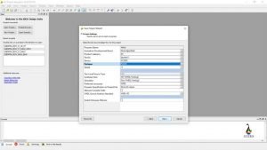
- Step 5: Now, in the editor section, you can see your model at the left top corner, inside the design tab and under the Hierarchy bar. Place your cursor on the folder named by you and do a right-click. Then Choose the New Source from the menu.
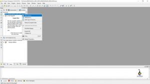
- Step 6: In the new window, choose the VHDL Module and paste the same name that you have copied in step 3, or you can get the name from the location tab. Click on next.

- Step 7: In the define module pop-up,
- Change the Architecture from ‘Behavioral’ to ‘Dataflow’.
- In the Port Name, Write A, B, and Y in the consecutive rows. Now for The Y marked row, Choose the direction as ‘out’ as it will be the output. You can change the direction from the down arrow associated with it.
- There will be another pop-up. Check if the porta is okay or not. Then click finish.

- Step 8: RTL SCHEMATIC CREATION
Now a code editor will be opened.
A. In the 40th line, you can ‘begin’. From that place, you have to write the dataflow code. The Code for our program will be –
Y <= A and B;
B. Save the code using Ctrl + S.
C. Now, on the left side of the window, under the design bar, you can see a tab named ‘process < model_name>’.
D. Expand the ‘Synthesis – XST’ from there.
E. Double click on the ‘Check Syntax’. It will show a green tick, denoting success.
F. Then, Double click on the ‘Synthesis – XST’. A green tick will have appeared here too.

G. Now click on the ‘View RTL Schematic’ to view the RTL implementation. A pop up will appear. Choose the second option and click on the next.
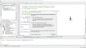
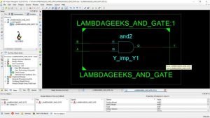
H. A diagram segment will be opened up.

I. Double click on the box to show the inside structure.
- Step 9: TEST BENCH CREATION
- Change the tab from Implementation to Simulation.

- Again, right-click on the first folder and choose the new source.

- Choose the ‘VHDL Test Bench’ and give a new file name. Click on the next.
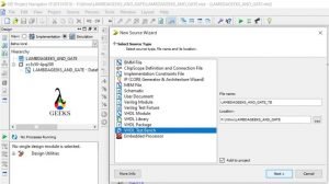
- After that, a window named Associate Source will be popped up to link your dataflow model with the test bench. Click on the model and click NEXT. Click on ‘Finish’ for the next window.

- A new code editor will be opened up.
Now, for an AND gate, we don’t need clock pulses. To delete or comment all the clock signals.
The clock signals are at line no. – 60, 72 to 78 and line no. 87.
Test bench code is written in the ‘Stimulus process section’.
You can start from the 90th line.
The code for test bench of AND gate is –
A <= ‘0’;
B <= ‘0’;
wait for 100 ns;
A <= ‘0’;
B <= ‘1’;
wait for 100 ns;
A <= ‘1’;
B <= ‘0’;
wait for 100 ns;
A <= ‘1’;
B <= ‘1’;
wait for 100 ns;
6. Now from the left side option, expand the Isim Simulator, and then double click on the ‘Behavioral Check Syntax’. A green tick will appear.

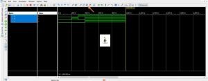
7. Now double-click on the ‘Simulate Behavioral Model’.
A window will be popped up. allow the software to access.
On the toolbar at the top, find out the option of zooming. Click on the third option to see the full view.
Click Here to Know About the VHDL CODING PROCESS!

Hi, I am Sudipta Roy. I have done B. Tech in Electronics. I am an electronics enthusiast and am currently devoted to the field of Electronics and Communications. I have a keen interest in exploring modern technologies such as AI & Machine Learning. My writings are devoted to providing accurate and updated data to all learners. Helping someone in gaining knowledge gives me immense pleasure.
Let’s connect through LinkedIn –